

Page 1
ADMINISTRATION
GUIDE
Cisco Small Business
RVS4000 4-Port Gigabit Security Router with VPN
Page 2

Cisco and the Cisco Logo are trademarks of Cisco Systems, Inc. and/or its affiliates in the U.S. and other countries. A listing of Cisco's trademarks can be found
at www.cisco.com/go/trademarks. Third party trademarks mentioned are the property of their respective owners. The use of the word partner does not imply
a partnership relationship between Cisco and any other company. (1005R)
© 2011 Cisco Systems, Inc. All rights reserved. OL-22605-02
Page 3

Contents
Chapter 1: Introduction 8
Chapter 2: Networking and Security Basics 9
An Introduction to LANs 9
The Use of IP Addresses 10
The Intrusion Prevention System (IPS) 11
Chapter 3: Planning Your Virtual Private Network (VPN) 13
Why do I need a VPN? 13
1) MAC Address Spoofing 14
2) Data Sniffing 14
3) Man in the middle attacks 14
What is a VPN? 15
VPN Router to VPN Router 16
Computer (using the Cisco QuickVPN Client software) to VPN Router 17
Chapter 4: Getting Started with the RVS4000 Router 18
Front Panel 18
Back Panel 19
Placement Options 20
Desktop Option 20
Stand Option 20
Wall Option 21
Installing the Router 22
Configuring the Router 23
Chapter 5: Setting Up and Configuring the Router 25
Setup 26
Setup > Summary 26
Setup > WAN 29
Setup > LAN 38
Cisco RVS4000 Security Router with VPN Administrato r G uide 3
Page 4

Setup > DMZ 40
Setup > MAC Address Clone 41
Setup > Advanced Routing 42
Setup > Time 44
Setup > IP Mode 45
Contents
Firewall 46
Firewall > Basic Settings 46
Firewall > IP Based ACL 48
Firewall > Internet Access Policy 51
Firewall > Single Port Forwarding 54
Firewall > Port Range Forwarding 55
Firewall > Port Range Triggering 56
ProtectLink 57
ProtectLink > ProtectLink Purchase 57
VPN 58
VPN > Summary 58
VPN > IPSec VPN 60
VPN > VPN Client Accounts 64
VPN > VPN Passthrough 66
QoS 67
QoS > Bandwidth Management 67
QoS > QoS Setup 70
QoS > DSCP Setup 71
Administration 72
Administration > Management 72
Router Access 72
Administration > Log 74
Administration > Diagnostics 76
Administration > Backup & Restore 78
Administration > Factory Default 79
Administration > Reboot 80
Administration > Firmware Upgrade 80
Cisco RVS4000 Security Router with VPN Administrato r G uide 4
Page 5

Contents
IPS 82
IPS > Configuration 82
IPS > P2P/IM 83
IPS > Report 84
IPS > Information 86
L2 Switch 86
L2 Switch > Create VLAN 86
L2 Switch > VLAN Port Setting 88
L2 Switch > VLAN Membership 89
L2 Switch > RADIUS 90
L2 Switch > Port Setting 91
L2 Switch > Statistics 92
L2 Switch > Port Mirroring 93
L2 Switch > RSTP 94
Status 95
Status > Gateway 95
Status > Local Network 97
Chapter 6: Using the VPN Setup Wizard 98
VPN Setup Wizard 98
Before You Begin 98
Running the VPN Setup Wizard 99
Building Your VPN Connection Remotely 109
Appendix A: Troubleshooting 116
Frequently Asked Questions 128
Appendix B: Using Cisco QuickVPN for Windows 2000, XP, or Vista 133
Overview 133
Before You Begin 133
Installing the Cisco QuickVPN Software 135
Installing from the CD-ROM 135
Cisco RVS4000 Security Router with VPN Administrato r G uide 5
Page 6

Downloading and Installing from the Internet 137
Contents
Using the Cisco QuickVPN Software 137
Distributing Certificates to QuickVPN Users 140
Appendix C: Configuring IPSec with a Windows 2000 or XP Computer 142
Introduction 142
Environment 143
Windows 2000 or Windows XP 143
RVS4000 143
How to Establish a Secure IPSec Tunnel 143
Establishing a Secure IPSec Tunnel 144
Appendix D: Gateway-to-Gateway VPN Tunnel 166
Overview 166
Before You Begin 166
Configuration when the Remote Gateway Uses a Static IP Address 167
Configuration when the Remote Gateway Uses a Dynamic IP Address 172
Configuration When Both Gateways Use Dynamic IP Addresses 177
Appendix E: Cisco ProtectLink Web Service 182
Overview 182
How to Access the Configuration Utility 182
How to Purchase, Register, or Activate the Service 183
ProtectLink 183
How to Use the Service 185
ProtectLink > Web Protection 185
ProtectLink > License 189
Appendix F: Specifications 190
Specifications 190
Performance 190
Cisco RVS4000 Security Router with VPN Administrato r G uide 6
Page 7

Setup/Config 190
Management 191
Security Features 191
QoS 191
Network 192
VPN 192
Routing 192
Layer 2 192
Environmental 193
Contents
Appendix G: Where to Go From Here 194
Product Resources 194
Related Documentation 195
Cisco RVS4000 Security Router with VPN Administrato r G uide 7
Page 8

Introduction
Thank you for choosing the Cisco RVS4000 4-Port Gigabit Security Router with
VPN. The 4-Port Gigabit Security Router with VPN is an advanced Internet-sharing
network solution for your small business needs. Like any router, it lets multiple
computers in your office share an Internet connection.
The 4-Port Gigabit Security Router with VPN also features a built-in 4-Port fullduplex 10/100/1000 Ethernet switch to connect four PCs directly, or you can
connect more hubs and switches to create as big a network as you need.
1
The Virtual Private Network (VPN) capability creates encrypted “tunnels” through
the Internet, allowing up to 5 remote offices and 5 traveling users to securely
connect into your office network from off-site. Users connecting through a VPN
tunnel are attached to your company’s network — with secure access to files,
email, and your intranet — just as if they were in the building. You can also use the
VPN capability to allow users on your small office network to securely connect out
to a corporate network. The QoS features provide consistent voice and video
quality throughout your business.
The 4-Port Gigabit Security Router with VPN can serve as a DHCP Server, and has
a powerful SPI firewall and Intrusion Prevention System (IPS) to protect your PCs
against intruders and most known Internet attacks. You can configure the router to
filter internal users’ access to the Internet, and has IP and MAC address filtering so
you can specify exactly who has access to your network. Configuration is a snap
with the web browser-based configuration utility.
This administration guide will give you all the information you need to connect, set
up, and configure your router.
Cisco RVS4000 Security Router with VPN Administrato r G uide 8
Page 9

Networking and Security Basics
This chapter describes networking and security basics. It includes these sections:
• An Introduction to LANs, page 9
• The Use of IP Addresses, page10
• The Intrusion Prevention System (IPS), page11
2
An Introduction to LANs
A router is a network device that connects two networks together.
The router connects your local area network (LAN), or the group of PCs in your
home or office, to the Internet. The router processes and regulates the data that
travels between these two networks.
The router’s Network Address T ranslation (NAT) technology protects your network
of PCs so users on the Internet cannot “see” your PCs. This feature keeps your
LAN remains private. The router protects your network by inspecting the first
packet received through the Internet po rt before delivering it to the final
destination on one of the Ethernet ports. The router inspects Internet port services
like the web server, ftp server, or other Internet applications, and, if allowed, it will
forward the packet to the appropriate PC on the LAN side.
Cisco RVS4000 Security Router with VPN Administrato r G uide 9
Page 10

Networking and Security Basics
The Use of IP Addresses
The Use of IP Addresses
IP stands for Int ernet Pr otocol. Ev ery device in an IP-based network, including PCs,
print servers, and routers, requires an IP address to identify its location, or
address, on the network. This applies to both the Internet and LAN connections.
There are two ways of assigning IP addresses to your network devices.
A static IP address is a fixed IP address that you assign manually to a PC or other
device on the network . Since a static IP address remains valid until you disable it,
static IP addressing ensures that the device assigned it will always have that same
IP address until you change it. Static IP addresses are commonly used with
network devices such as server PCs or print servers.
If you use the router to share your cable or DSL Internet connection, contact your
ISP to find out if they have assigned a static IP address to your account. If so, you
will need that static IP address when co nfiguring the router. You can get the
information from your ISP.
2
A dynamic IP address is automatically assigned to a device on the network. These
IP addresses are called dynamic because they are only temporarily assigned to
the PC or other device. After a certain time period, they expire and may change. If
a PC logs onto the network (or the Internet) and its dynamic IP address has
expired, the DHCP server will assign it a new dynamic IP address.
A DHCP server can either be a designated PC on the network or another network
device, such as the router. By default, the router’s Internet Connection Type is
Obtain an IP automatically (DHCP).
The PC or network device that obtains an IP address is called the DHCP client.
DHCP frees you from the requirement to assign an IP address manually when a
new user is added to your network.
For DSL users, many ISPs may require you to log on with a user name and
password to gain access to the Internet. This is a dedicated, high-speed
connection type called Point to Point Protocol over Ethernet (PPPoE). PPPoE is
similar to a dial-up connection, but PPPoE does not dial a phone number when
establishing a connection. It also will provide the router with a dynamic IP address
to establish a connection to the Internet.
By default, a DHCP server (on the LAN side) is enabled on the router. If you already
have a DHCP server on your network, you MUST disable one of the two DHCP
servers. If you run more than one DHCP server on your network, you will
experience network errors, such as conflicting IP addresses. To disable DHCP on
the router, see the Basic Setup section in Chapter 5, “Setting Up and
Configuring the Router.”
Cisco RVS4000 Security Router with VPN Administrato r G uide 10
Page 11

Networking and Security Basics
The Intrusion Prevention System (IPS)
NOTE Since the router is a device that connects two networks, it needs two IP
addresses—one for the LAN, and one for the Int ernet. In this Administration Guide,
you’ll see references to the “Internet IP address” and the “LAN IP address”.
Since the router uses NAT technology, the only IP address that can be seen from
the Internet f or y our network is the r outer’s Internet IP address. However, even this
Internet IP address can be blocked so the router and network seem invisible to the
Internet.
The Intrusion Prevention System (IPS)
IPS is an advanced technology to protect y our network from malicious attacks. IPS
works together with your SPI Firewall, IP Based Access Control List (ACL),
Network Address Port Translation (NAPT), and Virtual Private Network (VPN) to
achieve the highest level of security. IPS works by providing real-time detection
and prevention as an in-line module in a router.
2
The RVS4000 has hardware-based acceleration for real-time pattern matching to
detect malicious attacks. It actively filters and drops malicious TCP/UDP/ICMP/
IGMP packets and can reset TCP connections. This feature prevents network
worm attacks against client PCs and servers with various operating systems
including Windows, Linux, and Solaris. However, this system does not prevent
viruses contained in email attachments.
The P2P (Peer-to-Peer) and IM (Instant Messaging) control allows the system
administrator to prevent network users from using those protocols to
communicate with people over the Internet. This helps the administrators to set up
company policies on how to use the Internet bandwidth wisely.
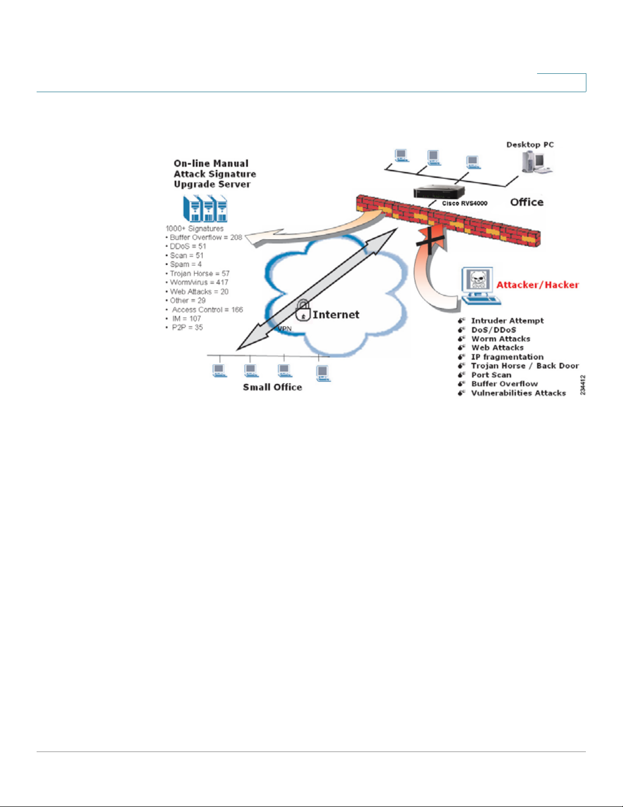
The signature file is the heart of the IPS system. It is similar to the Virus definition
file on your PC’s Anti-Virus software. IPS uses this file to match against packets
coming into the router and performs actions accordingly. The RVS4000 has a
signature file that contains 1000+ rules, which cover these categories: DDoS,
Buffer Overflow, Access Control, Scan, Trojan Horse, Misc., P2P, IM, Virus, Worm,
and Web Attacks.
Customers are encouraged to update their IPS signature file regularly to prevent
any new types of attacks on the Internet.
Cisco RVS4000 Security Router with VPN Administrato r G uide 11
Page 12
Networking and Security Basics
The Intrusion Prevention System (IPS)
IPS Scenarios
2
Cisco RVS4000 Security Router with VPN Administrato r G uide 12
Page 13

3
Planning Your Virtual Private Network (VPN)
This chapter provides information for planning your VPN. It includes these
sections:
• Why do I need a VPN?, page13
• What is a VPN?, page15
Why do I need a VPN?
Computer networking provides a flexibility not available when using an archaic,
paper-based system. With this flexibility, however, comes an increased risk in
security. Firewalls address this risk. Firewalls help to protect data inside of a local
network. But what do you do when information leaves your local network, when
emails go to their destination, or when you connect to your company’s network
from a hotel or remote office? How is your data protected?
A VPN can help. VPNs are called Virtual Private Networks because they secure
data moving outside of your network as if it were still within that network.
When data travels across the Internet from your computer, it is always open to
attacks. Y ou may already have a firewall, which helps protect data in your network
from being corrupted or intercepted by entities outside of your network. When
data moves outside of your network—when you send data to someone via email
or communicate with an individual over the Internet—the firewall no longer
protects your data.
At this point, your data becomes open to hackers who use a variety of methods to
steal not only the data you transmit but also your network login and security data.
Some of the most common methods are described in on the next page.
Cisco RVS4000 Security Router with VPN Administrato r G uide 13
Page 14

Planning Your Virtual Private Network (VPN)
Why do I need a VPN?
1) MAC Address Spoofing
Packets transmitted over a network, either your local network or the Internet, are
preceded by a packet header. These packet headers contain both the source and
destination information for that packet to transmit efficiently. A hacker can use this
information to spoof (or fake) a MAC address allowed on the network. With this
spoofed MAC address, the hacker can also intercept information meant for
another user.
2) Data Sniffing
Hackers use data “sniffing” to obtain network data as it travels through unsecured
networks, such as the Internet. Tools for just this kind of activity, such as protocol
analyzers and network diagnostic tools, are often built into operating systems and
allow the data to be viewed in clear text.
3
3) Man in the middle attacks
Once the hacker has either sniffed or spoofed enough information, he can now
perform a “man in the middle” attack. Hackers use this attack when data is
transmitted from one network to another, by rerouting the data to a new
destination. Even though the data never reaches its intended recipient, it appears
successful to the person who sent the data.
These are only a few of the methods hackers use, and they ar e always dev eloping
more. Without the security of your VPN, your data is constantly open to such
attacks as it travels over the Internet. Data travelling over the Internet often passes
through many different servers around the world before reaching its final
destination. That’s a long way to go for unsecured data and this is when a VPN
serves its purpose.
Cisco RVS4000 Security Router with VPN Administrato r G uide 14
Page 15

Planning Your Virtual Private Network (VPN)
What is a VPN?
What is a VPN?
A VPN, or Virtual Private Network, is a connection between two endpoints—a VPN
router, for instance—in different networks that allows private data to be sent
securely over a shared or public network, such as the Internet. This establishes a
private network that can send data securely between these two locations or
networks.
This is done by creating a “tunnel”. A VPN tunnel connects the two PCs or
networks and allows data to be transmitted over the Internet as if it were still
within those networks. Not a literal tunnel, it is a connection secured by encrypting
the data sent between the tw o networks.
VPN was created as a cost-effective alternative to using a private, dedicated,
leased line for a private network. Using industry standard encryption and
authentication techniques—IPSec, short for IP Security—VPN creates a secure
connection that, in effect, operates as if you were directly connected to your local
network. You can use VPN to create a secure network that links a central office
with branch offices, telecommuters, and/or professionals on the road (travelers
can connect to a VPN router by using any computer with the Cisco QuickVPN
Client software).
3
There are two basic ways to create a VPN connection:
• VPN router to VPN router
• Computer (using the Cisco QuickVPN Client software) to VPN router
The VPN router creates a “tunnel” or channel between two endpoints, so that data
transmissions between them are secure. A computer with the Cisco QuickVPN
Client software can be one of the two endpoints (refer to AppendixB, “Using
Cisco QuickVPN for Windows 2000, XP, or Vista”). If you choose not to run the
VPN client software, any computer with the built-in IPSec Security Manager
(Microsoft 2000 and XP) allows the VPN router to create a VPN tunnel by using
IPSec (refer to Appendix C, “Configuring IPSec with a Windows 2000 or XP
Computer”). Other versions of Microsoft operating systems require additional,
third-party VPN client software applications that support IPSec to be installed.
Cisco RVS4000 Security Router with VPN Administrato r G uide 15
Page 16
Planning Your Virtual Private Network (VPN)
What is a VPN?
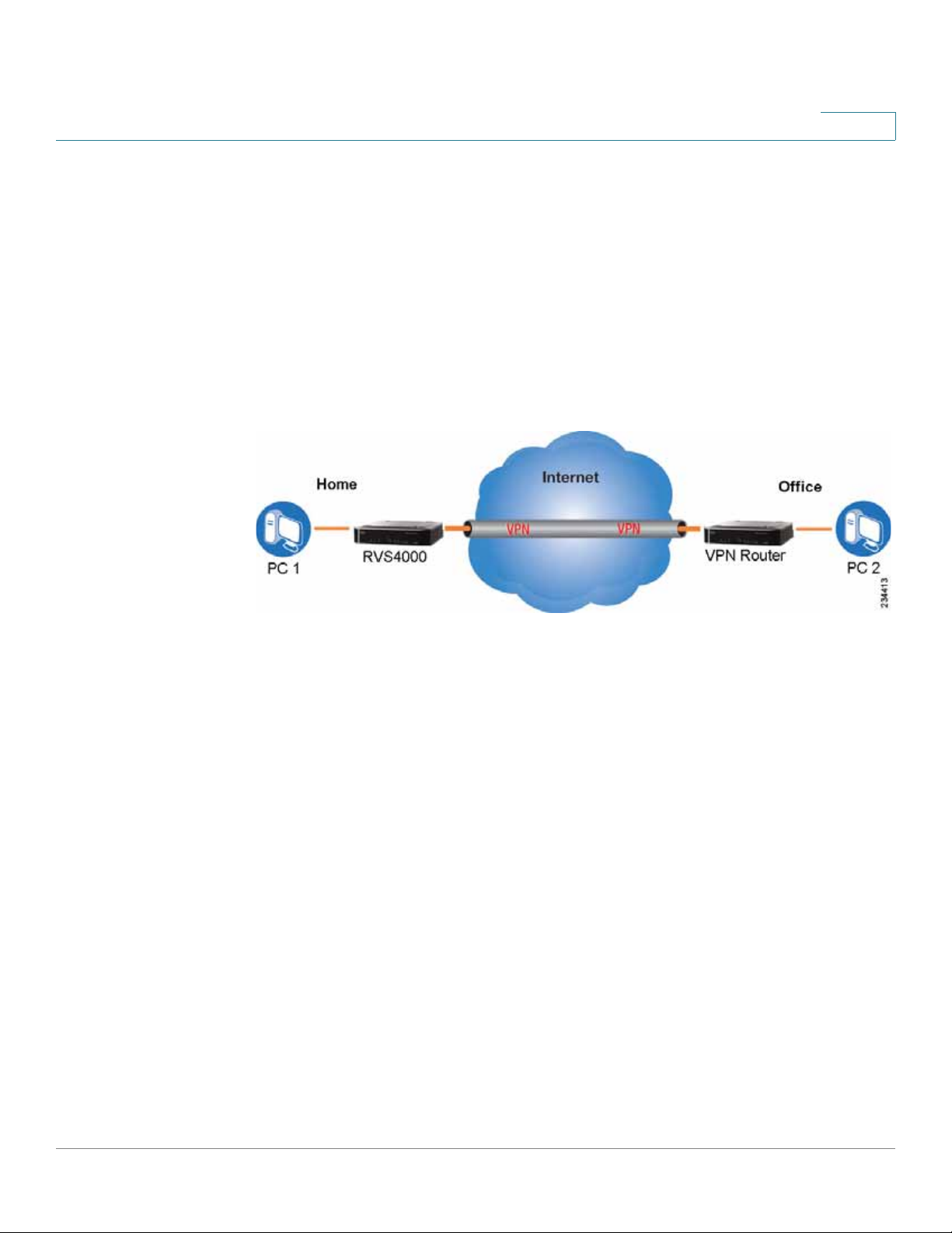
VPN Router to VPN Router
With a VPN-router-to-VPN-router VPN, a telecommuter uses his VPN router for his
always-on Internet connection. His router is configured with his office’s VPN
settings. When he connects to his offic e’s router, the t wo routers create a VPN
tunnel, encrypting and decrypting data. As VPNs utilize the Internet, distance is not
a factor. While using the VPN, the telecommuter now has a secure connection to
the central office’s network, as if he were physically connected. For more
information, refer to Appendix D, “Gateway-to-Gateway VPN Tunnel.”
VPN Router to VPN Router
3
Cisco RVS4000 Security Router with VPN Administrato r G uide 16
Page 17
Planning Your Virtual Private Network (VPN)
What is a VPN?
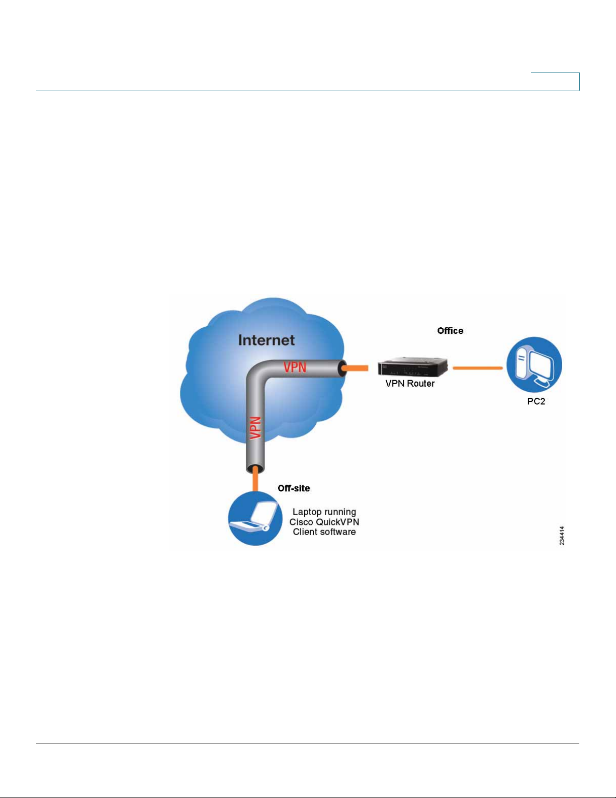
Computer (using the Cisco QuickVPN Client software) to VPN Router
In this illustration, you see an example of a computer-to-VPN router VPN. In her
hotel room, a traveling businesswoman connects to her ISP. Her notebook
computer has the Cisco QuickVPN Client software, which is configured with her
office’s IP address. She accesses the Cisco QuickVPN Client software and
connects to the VPN router at the central office. As VPNs utilize the Internet,
distance is not a factor. While using the VPN, she now has a secure connection to
the central office’s network, as if she were physically connected.
Computer to VPN Router
3
For additional information and instructions about creating your own VPN, please
visit www.cisco.com. You can also refer to Appendix B, “Using Cisco QuickVPN
for Windows 2000, XP, or Vista”, Appendix C, “Configuring IPSec with a
Windows 2000 or XP Computer” and Appendix D, “Gateway-to-Gateway VPN
Tunnel.”
Cisco RVS4000 Security Router with VPN Administrato r G uide 17
Page 18
Getting Started with the RVS4000 Router
This chapter describes the physical features of the RVS4000 router and explains
how to install the router. It includes these sections:
• Front Panel, page18
• Back Panel, page19
• Placement Options, page 20
4
Front Panel
• Installing the Router, page 22
• Configuring the Router, page 23
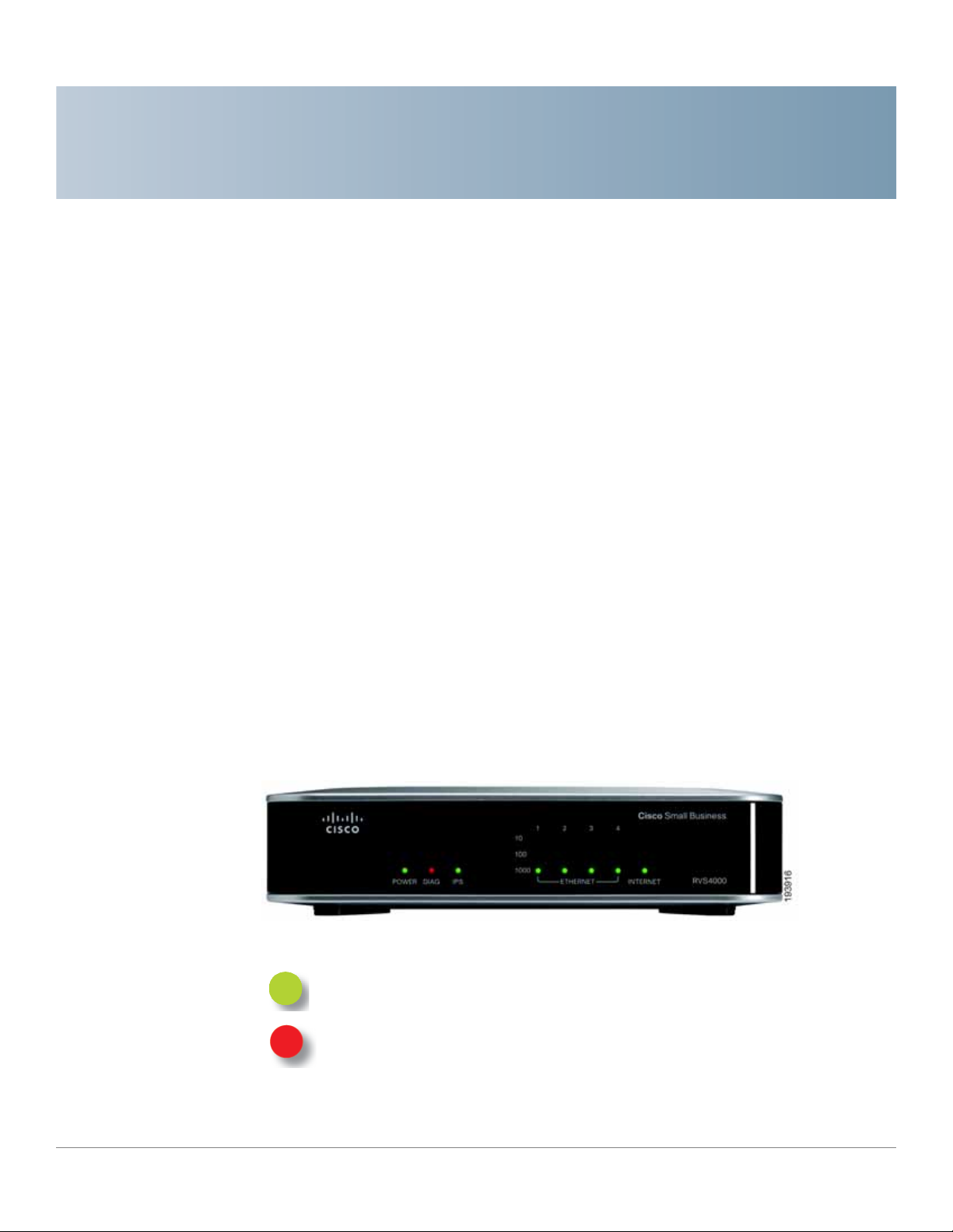
The LEDs are located on the front panel of the router.
Front Panel
POWER LED: Steady green when the router is powered on. Flashes when the
router is running a diagnostic test.
DIAG LED: Unlit when the system is ready. Flashes red during firmware
upgrades.
Cisco RVS4000 Security Router with VPN Administrato r G uide 18
Page 19
Getting Started with the RVS4000 Router
Back Panel
IPS LED: Steady green when the Intrusion Prevention System (IPS) function is
enabled. Unlit when IPS functions are disabled. Flashes green when an
external attack is detected. Flashes red when an internal attack is detected.
Ethernet Port LEDs 1-4: For each LAN port, there are three LEDs. Steady
green when the router is connected to a device at the speed indicated through
the corresponding port (1, 2, 3, or 4). Flashes green when a router is actively
sending or receiving data on the port.
INTERNET LED: Steady green to indicate the line speed of the device
attached to the Internet port. Flashes to indicates activity. If the router is
connected to a cable or DSL modem, typically the 100 LED is the only LED lit
up, indicating 100 Mbps.
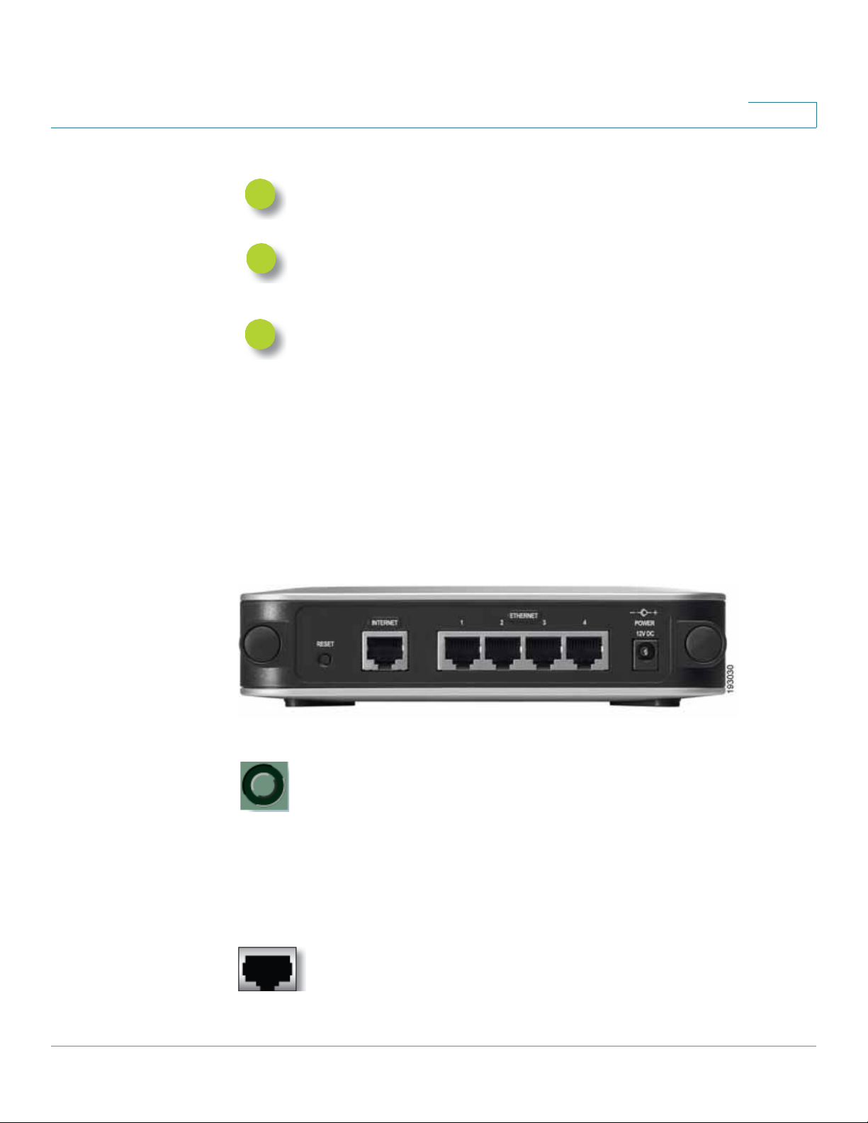
Back Panel
4
The Ethernet ports, Internet port, Reset button, and Power port are on the back panel of
the router.
Back Panel
RESET Button: You can use the Reset button in two ways:
• If the router has problems connecting to the Internet, press the
Reset button for just a second with a paper clip or a pencil tip.
This is similar to pressing the reset button on your PC to reboot it.
• If you experience extreme problems with the router and have
tried all other troubleshooting measures, press and hold the
Reset button for 10 seconds. This action restores the factory
defaults and clear all of the router settings, such as port
forwarding or a new password.
INTERNET Port: Provides a WAN connection to a cable modem or DSL
modem.
Cisco RVS4000 Security Router with VPN Administrato r G uide 19
Page 20
Getting Started with the RVS4000 Router
274946
POWER DIAG IPS ETHERNET
RVS4000
10
100
1000
1 2 3 4
INTERNET
Placement Options
ETHERNET Ports 1-4: Provide a LAN connection to network devices,
such as PCs, print servers, or additional switches.
POWER Port: Connects the router to power via the supplied AC power
adapter.
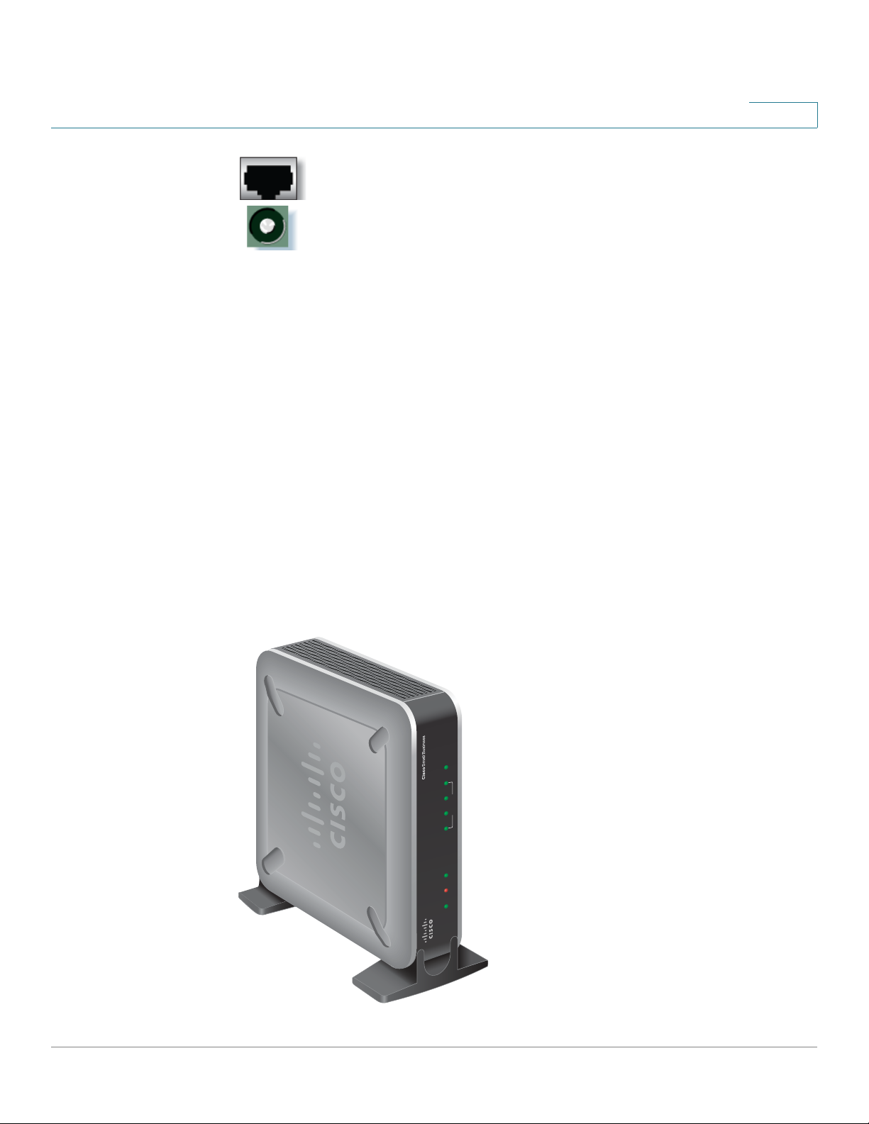
Placement Options
You can place the router horizontally on the rubber feet, mount it in the stand, or
mount it on the wall.
Desktop Option
4
For desktop placement, place the Cisco RVS4000 router horizontally on a surface
so it sits on its four rubber feet.
Stand Option
To install the router vertically in the supplied stands, follow the steps below.
Cisco RVS4000 Security Router with VPN Administrato r G uide 20
Page 21
Getting Started with the RVS4000 Router
193817
Wall
mount
slots
2-9/16
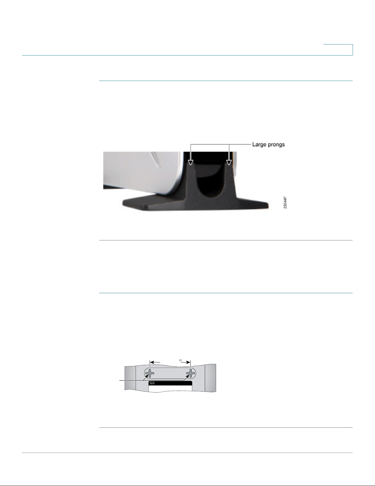
Placement Options
To place the router vertically, follow these steps.
STEP 1 Locate the left side panel of the router.
STEP 2 With the two large prongs of one of the stands facing outward, insert the short
prongs into the little slots in the router and push the stand upward until the stand
snaps into place.
4
STEP 3 Repeat step 2 with the other stand.
Wall Option
To mount the Cisco RVS4000 router on the wall, follow these steps.
STEP 1 Determine where you want to mount the router and install two screws (not
supplied) that are 2-9/16 in. apart (approximately 64.5 mm).
STEP 2 With the back panel pointing up (if installing vertically), line up the router so that the
wall-mount crisscross slots on the bottom of the access point line up with the two
screws.
STEP 3 Place the wall-mount slots over the screws and slide the router down until the
screws fit snugly into the wall-mount slots.
Cisco RVS4000 Security Router with VPN Administrato r G uide 21
Page 22
Getting Started with the RVS4000 Router
Installing the Router
Installing the Router
To prepare the router for installation complete these tasks:
• Obtain the setup information for your specific type of Internet connection
from your Internet Service Provider (ISP).
• Power off all of your network hardware, including the r outer, PCs, and cable
modem or DSL modem.
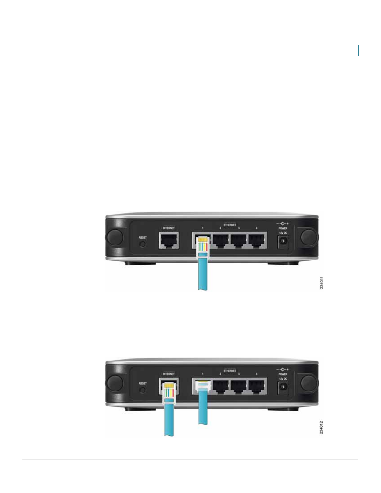
Perform the steps in this section to install the hardware.
STEP 1 Connect one end of an Ethernet network cable to one of the LAN ports
(labeled 1-4) on the back of the router. Connect the other end to an Ethernet port
on a PC.
4
STEP 2 Repeat step 1 to connect up to f our PCs, switches, or other network devices to the
router .
STEP 3 Connect an Ethernet network cable from your cable modem or DSL modem to the
Internet port on the back panel of the router.
Cisco RVS4000 Security Router with VPN Administrato r G uide 22
Page 23
Getting Started with the RVS4000 Router
Configuring the Router
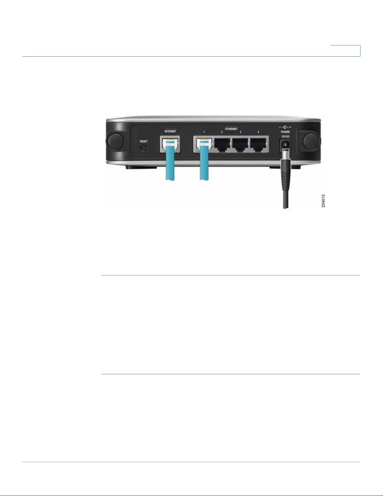
STEP 4 Power on the cable or DSL modem.
STEP 5 Connect the power adapter to the router’s Power port and plug the other end into
an electrical outlet.
4
STEP 6 The Power and Internet LEDs on the front panel lights up green as soon as the
power adapter is connected.
STEP 7 Power on the PCs.
The router hardware installation is now complete.
Configuring the Router
To configure the RVS4000, connect a PC to the router and launch the configuration
utility.
NOTE Before setting up the router, make sure your PCs are configured to obtain an IP (or
TCP/IP) address automatically from the router.
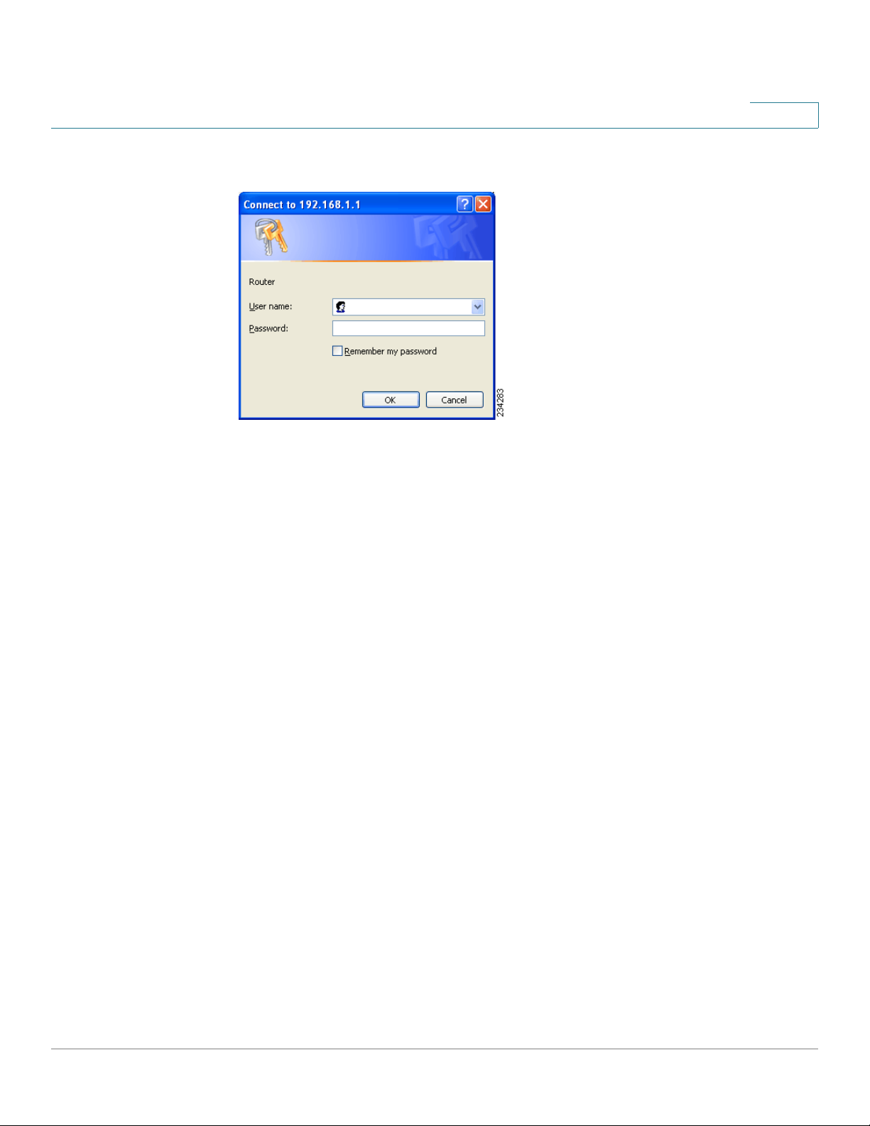
STEP 1 Launch a web browser, such as Internet Explorer or Mozilla Firefox.
STEP 2 In the Address field enter http://192.168.1.1 and press Enter.
STEP 3 In the User Name and Password fields, enter admin. The default user name and
password are admin.
Cisco RVS4000 Security Router with VPN Administrato r G uide 23
Page 24

Getting Started with the RVS4000 Router
Configuring the Router
STEP 4 Click OK.
For added security, you should later set a new password on the Administration >
Management page of the configuration utility.
STEP 5 The configuration utility appears with the Setup menu and Summary selected.
Click WAN under the Setup menu.
STEP 6 If requested by your ISP (usually cable ISPs), complete the Host Name and Domain
Name fields, and the MTU and MTU Size fields. Otherwise, leave the defaults.
STEP 7 In the WAN screen, choose an Internet Connection Type from the
drop-down menu. Depending on the Internet connection type that you select,
additional setup may be required.
The Internet Connection Types are:
Automatic Configuration - DHCP If you connect through DHCP or a
dynamic IP address from your ISP, keep this default setting.
4
Static IP If your ISP assigns you a static IP address, select Static IP from the
drop-down menu. Complete the Internet IP Address, Subnet Mask, Default
Gateway, and DNS fields. Enter at least one DNS address.
PPPoE If you connect through PPPoE, select PPPoE from the drop-down
menu. Complete the User Name and Password fields.
PPTP PPTP is used in Europe only. If you use a PPTP connection, check
with your ISP for the necessary setup information.
Heartbeat Signal Heartbeat Signal is used primarily in Australia. Check
with your ISP for the necessary setup information.
L2TP: L2TP is used mostly in Europe. Check with your ISP for the
necessary setup information.
STEP 8 When you finish entering your Internet connection settings, click Save.
STEP 9 Restart or power on your PC to obtain the new router setting.
STEP 10 Test the setup by opening your web browser from any computer and entering
http://www.cisco.com/smb.
Congratulations! The installation of the router is complete.
NOTE For more information about advanced settings and security options, refer to
Chapter 5, “Setting Up and Configuring the Router.”
Cisco RVS4000 Security Router with VPN Administrato r G uide 24
Page 25

Setting Up and Configuring the Router
This chapter explains how to configure these router functions:
• Setup, page 26
• Firewall, page 46
• VPN, page 58
• QoS, page 67
5
• Administration, page72
• IPS, page 82
• L2 Switch, page 86
• Status, page 95
Configure the router by using the built-in web-based configuration utility. To
access the c o nfiguration utility of the router, open your web browser and enter
http://192.168.1.1 into the Address field. Press the Enter key and t he Login
window appears.
NOTE The default IP address is 192.168.1.1. If the IP address has been changed via
DHCP or the console interface, enter the assigned IP address instead of the default.
The first time you open the configuration utility, enter admin (the default
username) in the Username field and enter admin in the Password field. Click the
OK button. You can change the password later from the Administration >
Management window.
Cisco RVS4000 Security Router with VPN Administrato r G uide 25
Page 26
Setting Up and Configuring the Router
Setup
Login Window
After you log in, the configuration utility starts. The menus appear as links in the
navigation pane on the left side of the screen. After you select a menu, a list of
windows appears. To perform a specific function, select a menu, and then select
the appropriate window. By default, the Setup menu’s Summary window appears
after you log in.
5
Setup
The utility’s menus and windows are described below. For brevity, window names
are listed in this format: Menu > Window.
Use the Setup menu to access all of the router’s basic setup functions. You can use
the router in most network settings without changing any of the default values.
Some users may need to enter additional information in order to connect to the
Internet through an ISP (Internet Service Provider) or broadband (DSL, cable
modem) carrier
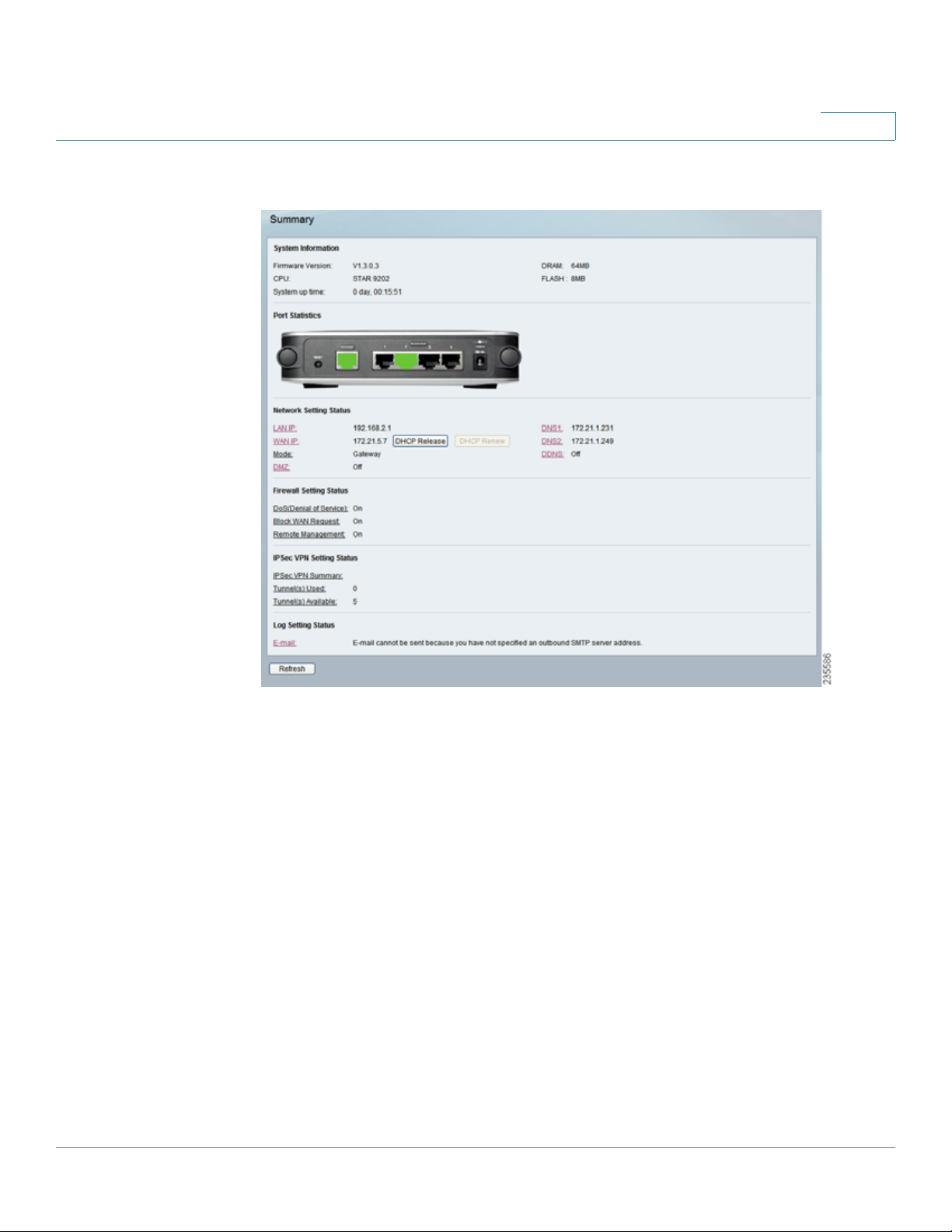
Setup > Summary
The Setup > Summa ry window displays a read-only summary of the router’s
basic information. Click a hyperlink (underlined text) to open a related page where
you can update the info rmation.
Cisco RVS4000 Security Router with VPN Administrato r G uide 26
Page 27
Setting Up and Configuring the Router
Setup
Setup > Summary
5
System Information
Firmware version Displays the router’s current firmware version.
CPU Displays the router’s CPU type.
System up time Displays the length of time that has elapsed since the router was
last reset.
DRAM Displays the amount of DRAM installed in the router.
Flash Displays the amount of flash memory installed in the router.
Port Statistics
This section displays color-coded status information on the r out er’s Ethernet ports:
• Green Indicates that the port has a connection.
• Black Indicates that the port has no connection.
Cisco RVS4000 Security Router with VPN Administrato r G uide 27
Page 28

Setting Up and Configuring the Router
Setup
Network Setting Status
LAN IP The IP address of the router’s LAN interface.
WAN IP The IP address of the router’s WA N interface. If this address was assigned
by using DHCP, click DHCP Release to release the address, or click DHCP Renew
to renew the address.
Mode The operating mode, Gateway or Router.
Gateway The Gateway address, which is the IP address of your ISP’s server.
DNS 1-2 The IP addresses of the Domain Name System (DNS) server(s) that the
router is using.
DDNS Indicates whether the Dynamic Domain Name System (DDNS) feature is
enabled.
5
DMZ Indicates whether the DMZ hosting feature is enabled.
Firewall Setting Status
DoS (Denial of Service) Indicates whether the DoS Protection feature is enabled
to block DoS attacks.
Block WAN Request Indicates whether the Block WAN Request feature is
enabled.
Remote Management Indicates whether the Remote Management feature is
enabled.
IPSec VPN Setting Status
IPSec VPN Summary Click the IPSec VPN Summary hyperlink to display the
VPN > Summary window.
Tunnel(s) Used Displays the number of VPN tunnels currently in use.
Tunnel(s) Available Displays the number of VPN tunnels that are available.
Log Setting Status
Email If this displays Email cannot be sent because you have not specified an
outbound SMTP server addres s, then you have not set up the mail server. Click
the Email hyperlink to display the Administration > Log window where you can
configure the SMTP mail server.
Cisco RVS4000 Security Router with VPN Administrato r G uide 28
Page 29
Setting Up and Configuring the Router
Setup
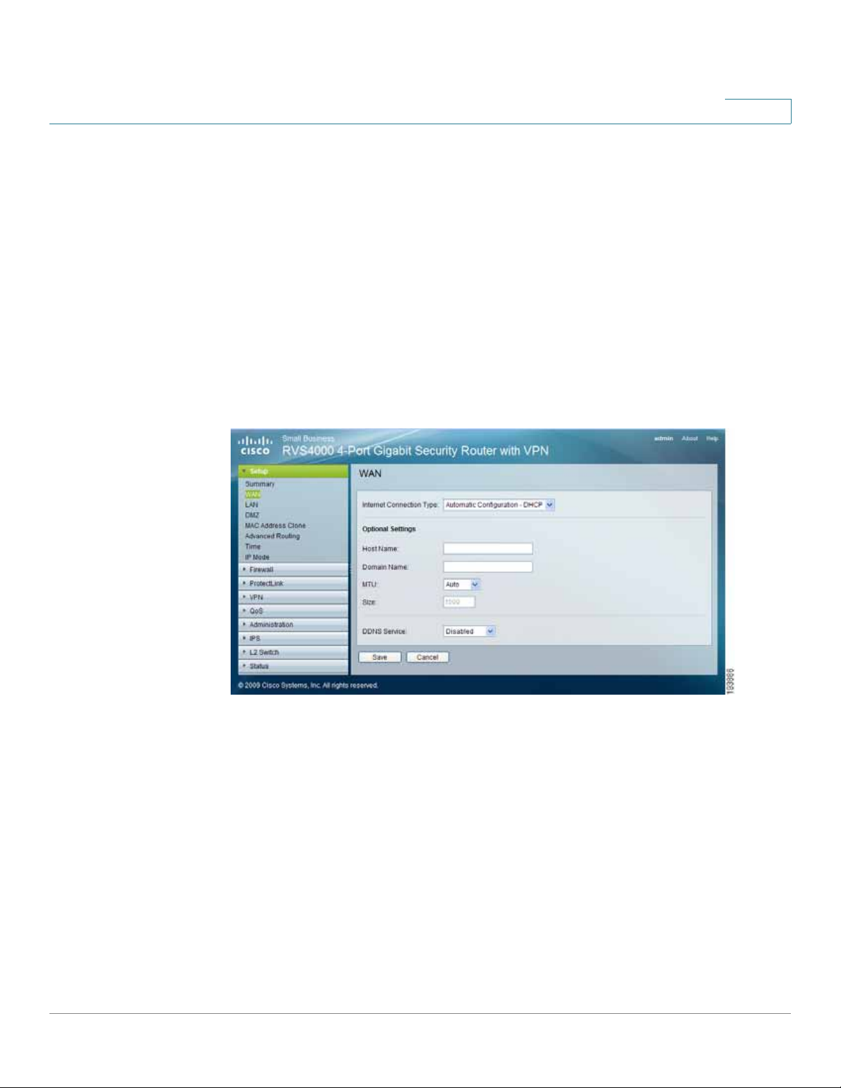
Setup > WAN
Internet Connection Type
The router supports six types of connections. Each Setup > WAN window and
available features differ, depending on the selected connection type.
Automatic Configuration - DHCP
By default, the router’s Configuration Type is set to Automatic Configuration DHCP, and it should be kept only if your ISP supports DHCP or you connect
through a dynamic IP address.
Automatic Configuration - DHCP
5
Cisco RVS4000 Security Router with VPN Administrato r G uide 29
Page 30
Setting Up and Configuring the Router
Setup
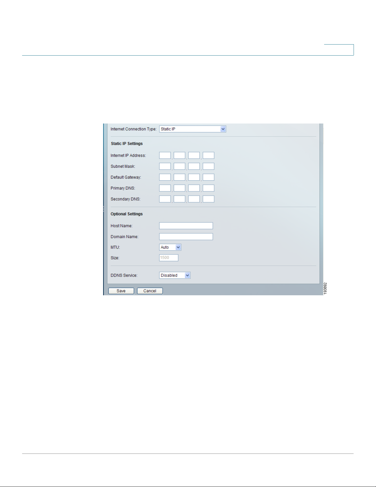
Static IP
If your connection uses a permanent IP address to connect to the Internet, then
select Static IP.
Static IP
5
Internet IP Address The router’s IP address, when seen from the WA N, or the
Internet. Your ISP will provide you with the IP Address to specify here.
Subnet Mask The router’s Subnet Mask, as seen by external users on the Internet
(including your ISP). Your ISP will provide you with the Subnet Mask.
Default Gateway Your ISP will provide you with the Default Gateway Address,
which is the ISP server’s IP address.
Primary DNS (Required) and Secondary DNS (Optional) Your ISP will provide
you with at least one DNS (Domain Name System) Server IP Address.
Click Save to save your changes, or click Cancel to undo your changes.
Cisco RVS4000 Security Router with VPN Administrato r G uide 30
Page 31

Setting Up and Configuring the Router
Setup
PPPoE
Some DSL-based ISPs use PPPoE (Point-to-Point Protocol over Ethernet) to
establish Internet connections. If you connect to the Internet through a DSL line,
check with your ISP to see if they use PPPoE. If they do, enable PPPoE.
PPPoE
5
User Name and Password Enter the User Name and Password provided by your
ISP.
Connect on Demand: Max Idle Time
Internet connection after it has been inactive for a specified period of time (Max
Idle Time) , and then automatically re-establish the connection as soon as you
attempt to access the Internet again. To activate Connect on Demand, select the
Connect on Demand option and enter in the Max Idle Time field the number of
minutes of inactivity that must elapse before your Internet connection is
terminated automatically.
Cisco RVS4000 Security Router with VPN Administrato r G uide 31
You can configure the router to cut the
Page 32

Setting Up and Configuring the Router
Setup
Keep Alive: Redial period If you select this option, the router periodically checks
your Internet connection. If you are disconnected, then the router automatically reestablishes your connection. To use this option, click the radio button next to Keep
Alive. In the Redial Period field, specify how often you want the router to check
the Internet connection. The default Redial Period is 30 seconds.
Click Save to save your changes, or click Cancel to undo your changes.
PPTP
Point-to-P oint Tunneling Protocol (PPTP) is a service that applies to connections in
Europe and Israel only.
PPTP
5
IP Address The router’s IP address, when seen from the WAN, or the Internet. Your
ISP will provide you with the IP Address you need to specify here.
Subnet Mask The router’s Subnet Mask, as seen by external users on the Internet
(including your ISP). Your ISP will provide you with the Subnet Mask.
Default Gateway Your ISP will provide you with the Default Gateway Address.
PPTP Server Enter the IP address of the PPTP server.
User Name and Password Enter the User Name and Password provided by your
ISP.
Cisco RVS4000 Security Router with VPN Administrato r G uide 32
Page 33

Setting Up and Configuring the Router
Setup
Connect on Demand: Max Idle Time Y ou can configure the router to cut the
Internet connection after it has been inactive for a specified period of time (Max
Idle Time) , and then automatically re-establish the connection as soon as you
attempt to access the Internet again. To activate Connect on Demand, select the
Connect on Demand option and enter in the Max Idle Time field the number of
minutes of inactivity that must elapse before your Internet connection is
terminated automatically.
Keep Alive: Redial period If you select this option, the router periodically checks
your Internet connection. If you are disconnected, then the router automatically reestablishes your connection. To use this option, click the radio button next to Keep
Alive. In the Redial Period field, specify how often you want the router to check
the Internet connection. The default Redial Period is 30 seconds.
Click Save to save your changes, or click Cancel to undo your changes.
Heart Beat Signal
5
Heart Beat Signal is a service used in Australia. Check with your ISP for the
necessary setup information.
Heart Beat Signal
User Name and Password Enter the User Name and Password provided by your
ISP.
Heart Beat Server Enter the IP address of the Heart Beat server.
Cisco RVS4000 Security Router with VPN Administrato r G uide 33
Page 34

Setting Up and Configuring the Router
Setup
Connect on Demand: Max Idle Time Y ou can configure the router to cut the
Internet connection after it has been inactive for a specified period of time (Max
Idle Time) , and then automatically re-establish the connection as soon as you
attempt to access the Internet again. To activate Connect on Demand, select the
Connect on Demand option and enter in the Max Idle Time field the number of
minutes of inactivity that must elapse before your Internet connection is
terminated automatically.
Keep Alive: Redial period If you select this option, the router periodically checks
your Internet connection. If you are disconnected, then the router will automatically
re-establishes your connection. To use this option, click the radio button next to
Keep Alive. In the Redial Period field, specify how often you want the router to
check the Internet connection. The default Redial Period is 30 seconds.
Click Save to save your changes, or click Cancel to undo your changes.
L2TP
5
Layer 2 Tunneling Protocol (L2TP) is a service that tunnels Point-to-Point
Protocol (PPP) across the Internet. It is used mostly in European countries. Check
with your ISP for the necessary setup information.
L2TP
IP Address The router’s IP address, when seen from the WAN, or the Internet. Your
ISP will provide you with the IP Address you need to specify here.
Subnet Mask The router’s Subnet Mask, as seen by external users on the Internet
(including your ISP). Your ISP will provide you with the Subnet Mask.
Cisco RVS4000 Security Router with VPN Administrato r G uide 34
Page 35

Setting Up and Configuring the Router
Setup
Gateway Your ISP will provide you with the Default Gateway Address.
L2TP Server Enter the IP address of the L2TP server.
User Name and Password Enter the User Name and Password provided by your
ISP.
Connect on Demand: Max Idle Time Y ou can configure the router to cut the
Internet connection after it has been inactive for a specified period of time (Max
Idle Time) , and then automatically re-establish the connection as soon as you
attempt to access the Internet again. To activate Connect on Demand, select the
Connect on Demand option and enter in the Max Idle Time field the number of
minutes of inactivity that must elapse before your Internet connection is
terminated automatically.
Keep Alive: Redial period If you select this option, the router periodically checks
your Internet connection. If you are disconnected, then the router automatically reestablishes your connection. To use this option, click the radio button next to Keep
Alive. In the Redial Period field, you specify how often you want the router to
check the Internet connection. The default Redial Period is 30 seconds.
5
Click Save to save your changes, or click Cancel to undo your changes.
Cisco RVS4000 Security Router with VPN Administrato r G uide 35
Page 36

Setting Up and Configuring the Router
Setup
Optional Settings (Required by some ISPs)
Your ISP may require some of these settings. Verify with your ISP before making
any changes.
Optional Set tings
5
Host Name Some ISPs, usually cable ISPs, require a host name as identification.
You may have to check with your ISP to see if your broadband Internet service has
been configured with a host name. In most cases, you can leave this field blank.
Domain Name Some ISPs, usually cable ISPs, require a domain name as
identification. You may have to check with your ISP to see if your broadband
Internet service has been configured with a domain name. In most cas es, you can
leave this field blank.
MTU MTU is the Maximum Transmission Unit. It specifies the largest packet size
permitted for Internet transmission. Select Manual if you want to manually enter
the largest packet size that can be transmitted. To allow the router to select the
best MTU for your Internet connection, keep the default setting, Auto.
Size When Manual is selected in the MTU field, this option is enabled. It is
recommended that you set this value within the range of 1200 to 1500, but the
value can be defined between 128 and 1500.
Cisco RVS4000 Security Router with VPN Administrato r G uide 36
Page 37

Setting Up and Configuring the Router
Setup
DDNS Service DDNS Service is disabled by default. To enable DDNS Service,
follow these instructions:
Connect The Connect button is displayed when DDNS is enabled. You can click
this button to contact the DDNS server to manually update your IP address
information. The Status area on this window is also updated.
STEP 1 Sign up for DDNS Service:
• DynDNS - Sign up for DDNS service at www.dyndns.org and write down
your User Name, Password, and Host Name information.
• TZ O - Sign up f or DDNS service at www.tzo.com and write down y our email
address, password and domain name information.
STEP 2 Select your DDNS service provider.
STEP 3 Configure these fields:
5
• User Name (DynDNS) or Email address (TZO).
• Password
• Host Name (DynDNS) or Domain name (TZO)
• Custom DNS (DynDNS)
STEP 4 Click Save.
The router advises the DDNS Service of your current WAN (Internet) IP address
whenever this address changes. If you use TZO, you should NOT use the TZO
software to perform this “IP address update”.
Cisco RVS4000 Security Router with VPN Administrato r G uide 37
Page 38

Setting Up and Configuring the Router
Setup
Setup > LAN
The Setup > LAN window allows you to change the router’s local network
settings.
Setup > LAN
5
Cisco RVS4000 Security Router with VPN Administrato r G uide 38
Page 39

Setting Up and Configuring the Router
Setup
VLAN Select the VLAN for the DHCP server from the drop-down menu.
NOTE This option appears only if you have created at least one VLAN from the L2 Switch
> Create VL AN window.
IPv4
The router’s Local IP Address and Subnet Mask appear here. In most cases, you
can keep the defaults.
Local IP Address The default value is 192.168.1.1.
Subnet Mask The default value is 255.255.255.0.
Server Settings (DHCP)
You can use the router as your network’s DHCP (Dynamic Host Configuration
Protocol) server, which automatically assigns an IP address to each PC on your
network. Unless you already have one, it is highly recommended that you leav e the
router enabled as a DHCP server.
5
DHCP Ser ver DHCP is already enabled by factory default. If you already have a
DHCP server on your network, or if you don’t want a DHCP server, then select
Disabled (no other DHCP features will be available). If you already have a DHCP
server on your network, and you want this router to act as a Relay for that DHCP
Server, select DHCP Relay, then enter the DHCP Server IP Address. If you disable
DHCP, assign a static IP address to the router.
Starting IP Address Enter a value for the DHCP server to start with when it issues
IP addresses. This value must be 192.168.1.2 or greater, but smaller than
192.168.1.254, because the default IP addre ss for the router is 192.168.1.1, and
192.168.1.255 is the broadcast IP address.
Maximum Number of DHCP Users Enter the maximum number of PCs that you
want the DHCP server to assign IP addresse s to. This number cannot be greater
than 253. In order to determine the DHCP IP Address range, add the starting IP
address (e.g., 100) to the number of DHCP users.
Client Lease Time The amount of time a DHCP client can keep the assigned IP
address before it sends a renewal request to the DHCP server.
Static DNS 1 -3 If applicable, enter the IP address(es) of your DNS server(s).
WINS The Windows Internet Naming Service (WINS) provides name resolution
service (similar to DNS) in Windows networks. If you use a WINS server, enter that
server’s IP Address here. Otherwise, leave this blank.
Cisco RVS4000 Security Router with VPN Administrato r G uide 39
Page 40

Setting Up and Configuring the Router
Setup
Static IP Mapping
Static IP Mapping is used to bind a specific IP address to a specific MAC address.
This helps external (WAN) users to access LAN servers that are advertised
through NAPT port forwarding. You can define up to 50 entries.
Static IP Address Enter the IP address to be mapped.
MAC Address Enter the MAC address to be mapped.
Host Name Enter the host name to be mapped.
Click Add to create the entry and add it to the list. To modify an existing entry,
select it from the list, edit the appropriate field(s), and then click Modify. To delete
an entry, select it and click Remove.
IPv6
5
IPv6 Address If your network has implemented IPv6, enter the proper IPv6
address in this field.
Prefix Length Enter the appropriate IPv6 prefix length.
Router Advertisement When enabled, this option allows IPv6 hosts to configure
their IP addresses automatically by using the IPv6 prefix broadcast by the router.
DHCPv6
To enable the DHCP v6 feature, select Enable. To disable DHCP v6, select Disable.
Lease time Enter the lease time in minutes.
DHCP6 address range start Enter the starting DHCP v6 IP address.
DHCP6 address range end Enter the ending DHCP v6 IP address.
Primary DNS Enter the Primary DHCP v6 DNS server address.
Secondary DNS Enter the Secondary DHCP v6 DNS server address.
Click Save to save your changes, or click Cancel to undo your changes.
Setup > DMZ
You can set up a DMZ to allow one local PC to be exposed to the Internet for a
special service such as Internet gaming and videoconferencing. Whereas Port
Range Forwarding can only forward a maximum of 10 ranges of ports, DMZ
hosting forwards all the ports for one PC at the same time.
Cisco RVS4000 Security Router with VPN Administrato r G uide 40
Page 41

Setting Up and Configuring the Router
Setup
Setup > DMZ
DMZ Hosting This feature allows one local PC to be exposed to the Internet for
use of a special-purpose service such as Internet gaming and videoconferencing.
To use this feature, select Enable. To disable the DMZ feature, select Disable.
DMZ Host IP Address To expose one PC, enter the computer’s IP address.
Click Save to save your changes, or click Cancel to undo your changes.
5
Setup > MAC Address Clone
Some ISPs require that you register a MAC address. This feature “clones” your
network adapter’s MAC address onto the router, and prevents you from having to
call your ISP to change the registered MAC address to the router’s MAC address.
The router’s MAC address is a 12-digit code assigned to a unique piece of
hardware for identification.
Setup > MAC Address Clone
MAC Address Clone Select Enabled or Disabled from the drop-down menu.
MAC Address Enter the MAC Address registered with your IS P in this field.
Clone My PC’s MAC When MAC Address Clone is enabled, click this button to
copy the MAC address of the network adapter in the computer that you use to
connect to the web interface.
Click Save to save your changes, or click Cancel to undo your changes.
Cisco RVS4000 Security Router with VPN Administrato r G uide 41
Page 42

Setting Up and Configuring the Router
Setup
Setup > Advanced Routing
Setup > Advanced Routing
5
Operating Mode
Operation Mode Select the Operating mode for this router:
• Gateway The normal mode of operation. This allows all devices on your
LAN to share the same WAN (Internet) IP address. In Gateway mode, the
NAT (Network Address Translation) mechanism is enabled.
• Router You either need another router to act as the Internet Gateway, or all
PCs on your LAN must be assigned (fixed) Internet IP addresses. In Router
mode, the NAT mechanism is disabled.
Dynamic Routing
You can use the router’s dynamic routing f eature t o automatically adjust t o physical
changes in the network’s layout. The router can use the dynamic RIP protocol to
calculate the most efficient route f or the network’s data packets to travel between
the source and the destination, based upon the shortest paths. The RIP protocol
regularly broadcasts routing information to other routers on the network.
RIP (Routing Information Protocol) If you want the router to use the RIP protocol,
select Enabled; otherwise, keep the default setting, Disabled.
Cisco RVS4000 Security Router with VPN Administrato r G uide 42
Page 43

Setting Up and Configuring the Router
Setup
RIP Send Packet Version Choose the TX protocol to use to transmit data on the
network: RIPv1 or RIPv2. This setting should match the version supported by
other routers on your LAN.
RIP Recv Packet Version Choose the RX protocol to use to receive data from the
network: RIPv1 or RIPv2. This should match the version supported by other
routers on your LAN.
Static Routing
Sometimes you may prefer to use static routes to build your routing table instead
of using dynamic routing protocols. Static routes do not require CPU resources to
exchange routing information with a peer router. You can also use static routes to
reach peer routers that do not support dynamic routing protoc ols. Static routes
can be used together with dynamic routes. Be careful not to introduce routing
loops in your network.
5
To set up static routing, you should add route entries in the routing table that tell
the router where to forward packets to specific IP destinations.
Enter this data to create a static route entry:
Select Set Number Select the set number (routing table entry number) that you
wish to view or configure. If necessary, click Delete This Entry to clear the entry.
Destination IP Address Enter the network address of the remote LAN segment.
For a standard Class C IP domain, the network address is the first three fields of
the Destination LAN IP, while the last field should be zero.
Subnet Mask Enter the Subnet Mask used on the destination LAN IP domain. For
Class C IP domains, the Subnet Mask is 255.255.255.0.
Gateway If this router is used to connect your network to the Internet, then your
gateway IP is the r outer’s IP Address. If you have another r outer that manages your
network’s Internet connection, enter the IP Address of that router instead.
Hop Count This value gives the number of nodes that a data packet passes
through before it reaches its destination. A node is any device on the network,
such as switches, PCs, etc. The maximum hop count value is 16.
Show Routing Table Click this button to show the routing table established either
through dynamic or static routing methods.
Inter-VLAN Routing
Inter-VLAN Routing Select Enable to allow packets to be routed between VLANs
in different subnets. The default is Enable.
Cisco RVS4000 Security Router with VPN Administrato r G uide 43
Page 44

Setting Up and Configuring the Router
Setup
Click Save to save your changes, or click Cancel to undo your changes.
Setup > Time
Setup > Time
5
Set the local time Manually If you wish to enter the time and dat e manually, select
this option, then select the Date from the drop-down fields and enter the hour,
minutes, and seconds in the Time fields in 24-hour format. For example, for 10:00
pm, enter 22 in the hours field, 0 in the minutes field, and 0 in the seconds field.
Set the local time using Network Time Protocol (NTP) Automatically If you wish
to use a Network Time Protocol server to set the time and date, select this option,
and then complete these fields:
Time Zone Select the time zone for your location and your time setting is
synchronized over the Internet.
Auto Daylight Saving If your location observes daylight savings time, select the
Enable option.
User-defined NTP Server To specify a user-defined NTP server, select the Enable
option, then enter the NTP Server’s IP address in the NTP Server IP field.
NTP Server IP If the User-defined NTP Server option is set to Enable, enter the IP
address of the NTP server.
Click Save to save your changes, or click Cancel to undo your changes.
Cisco RVS4000 Security Router with VPN Administrato r G uide 44
Page 45
Setting Up and Configuring the Router
Setup
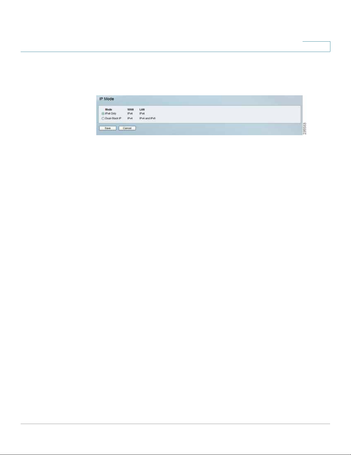
Setup > IP Mode
Setup > IP Mode
5
IPv4 Only
Dual-Stack IP Select this option to use IPv4 on the Internet and IPv4 and IPv6 on
the local network. IPv6 hosts in the LAN are connected to remot e IPv6 islands over
6to4 tunnels (per RFC3056).
Click Save to save your settings or click Cancel to undo your changes.
Select this option to use IPv4 on the Internet and local network.
Cisco RVS4000 Security Router with VPN Administrato r G uide 45
Page 46

Setting Up and Configuring the Router
Firewall
Firewall
Use the Firewall menu to configure the router to deny or allow specific internal
users from accessing the Internet. You can also configure the router to deny or
allow specific Internet users from accessing the internal servers . You can set up
different packet filters for different users on the internal (LAN) side or external
(WAN) side based on their IP addresses or their netw ork Port number.
Firewall > Basic Settings
Firewall > Basic Settings
5
Firewall When this feature is enabled, the router’s NAT firewall feature is enabled.
DoS Protection When this feature is enabled, the router blocks DoS (Denial of
Service) attacks. A DoS attack does not attempt to steal data or damage your PCs,
but overloads your Internet connection so you can not use it.
Block WAN Request When this featur e is enabled, the r outer filters out
anonymous requests from the WAN.
Remote Management This feature allows you to use an http or https port to
remotely manage the router. To enable this feature, select Enable and enter the
port number in the Port field, then configure the HTTPS and Remote IP address
settings that appear below.
Cisco RVS4000 Security Router with VPN Administrato r G uide 46
Page 47

Setting Up and Configuring the Router
Firewall
HTTPS This option limits access to the configuration utility from the WAN to https
sessions only. An https session uses SSL encr yption, which provides better
protection for your remote session than does http. The default is Enable.
• Remote IP address Select the appropriate value to specify which external
IP address(es) can access the router.
• Any IP Address Allows access from any external IP address.
• Single IP Address Allows access from the single IP address that you enter
in the field provided.
• IP Range Allows access from a range of IP addresses that you enter in the
field provided.
• Subnet Allows access from the Subnet that you enter in the field provided.
Remote Upgrade This option allow s you to upgrade the router remotely. To allow
remote upgrade, select Enable. The Remote Management feature must be set to
Enable as well. The default is Disable.
5
Multicast Passthrough If an IGMP Proxy is running on the router, enable this
feature to allow IP Multicast traffic to come in from the Internet. The default is
Disable.
SIP Application Layer Gateway When this feature is enabled, the SIP Application
Layer Gateway (ALG) allows Session Initiation Protocol (SIP) packets (used for
Voice over IP) to traverse the NAT firewall. You can disable this feature if the VoIP
service provider uses other NAT traversal solutions such as STUN, TURN, and ICE.
Block Place a checkmark next to the Web features that you wish to restrict.
• Java Java is a programming language for websites. If you deny Java, you
run the risk of not having access to Internet sites that use this programming
language.
• Cookies A cookie is data stored on your PC and used by Internet sites
when you interact with them, so you may not want to deny cookies.
• ActiveX ActiveX is a Microsoft (Internet Explorer) programming language
for websites. If you deny ActiveX, you run the risk of not having access to
Internet sites that use this programming language. Also, Windows Update
uses ActiveX, so if this is blocked, Windows update will not work.
• Access to Proxy HTTP Server If local users have access to WAN proxy
servers, they may be able to circumvent the router’s content filters and
access Internet sites blocked by the router . Denying Pr oxy will block access
to any WAN proxy servers .
Cisco RVS4000 Security Router with VPN Administrato r G uide 47
Page 48

Setting Up and Configuring the Router
Firewall
Firewall > IP Based ACL
The IP-Based ACL window allows you to create an Access Control List (ACL) with
up to 50 rules. Each ACL rule denies or allows access to the network based on
various criteria including priority, service type, interfac e, source IP address,
destination IP address, day of the week, and time of day.
Firewall > IP Based ACL
5
Priority The rule’s priority.
Enable This indicates whether the rule is enabled or disabled.
Action The rule’s action, either Allow or Deny.
Service The service(s) to which the rule applies.
Source Interface The source interface, either WAN, LAN, or ANY.
Source The source IP address, which can be one specific IP address, ANY (all IP
addresses), a range of IP addresses, or a specific IP subnet.
Destination The destination IP address, which can be one specific IP address,
ANY (all IP addresses), a range of IP addresses, or a specific IP subnet .
Time The time of day when the rule is in effect, either Any Time (24 hours) or a
specific start and end time.
Day The day(s) of the week when the rule is in effect. This may be Any Day or a
user-specified set of days.
Edit button Click Edit at the end of a row to edit the associated rule.
Delete button Click Delete at the end of a row to delete the associated rule.
Cisco RVS4000 Security Router with VPN Administrato r G uide 48
Page 49

Setting Up and Configuring the Router
Firewall
To add a new rule to the ACL rule table, click Add New Rule and the Edit IP ACL
Rule window appears. Follow the instructions in the section below to create a new
ACL rule. To disable all the rules without deleting them, click Disable All Rules. To
delete all the rules from the table, click Delete All Rules.
Editing IP ACL Rules
Editing IP ACL Rules
5
Action Select the desired action, Allow or Deny, from the drop-down menu.
Service Select the service types to which the rule applies. You can either select
one of the predefined services in the drop-down menu; select ALL to allow or
deny all types of IP traffic; or define a new service by clicking Service
Management to bring up the Service Management window, then the new
service’s Name, select the Type (TCP, UDP, or TCP/UDP), enter the Start Port and
Finish Port, then click Save. The new service appears in the drop-down menu on
the Edit IP ACL Rule window.
Log Select this option to log all traf fic that is filtered by this rule.
Log Prefix Enter a text string to prepend to each matched event in the log.
Cisco RVS4000 Security Router with VPN Administrato r G uide 49
Page 50

Setting Up and Configuring the Router
Firewall
Source Interface Select the source interface, WAN, LAN, or ANY, from the drop-
down menu.
Source IP To apply the rule to one source IP address, select Single from the drop-
down menu, then enter the address in the field. To apply the rule to all source IP
addresses , select ANY from the drop-down menu. To apply the rule to a range of
IP addresses, select Range and enter the starting and ending IP addresses. To
apply the rule to a subnet, select Net and enter the IP address and subnet mask.
Destination IP To apply the rule to one destination IP address, select Single from
the drop-down menu, then enter the address in the field. To apply the rule to all
destination IP addresses, select ANY from the drop-down menu. To apply the rule
to a range of IP addresses, select Range and enter the starting and ending IP
addresses. To apply the rule to a subnet, select Net and enter the IP address and
subnet mask.
Days To make the rule apply on a daily basis, select Everyday. To make the rule
apply on specific days of the week only, select the desired days.
5
Time To make the rule apply for an entire day, select 24 Hours. To make the rule
apply only during a specific period of the day, enter the starting time in the From
field and the ending time in the To field.
Click Save to save your changes, or click Cancel to undo your changes. Click
Return to return to the IP-Based ACL window.
Cisco RVS4000 Security Router with VPN Administrato r G uide 50
Page 51

Setting Up and Configuring the Router
Firewall
Firewall > Internet Access Policy
Firewall > Internet Acces s Policy
5
You can manage access to your network by configuring a policy. Use the settings
on this window to establish an access policy. Select a policy from the drop-down
menu to display the settings for a policy. Yo u can then perform these operations:
• Create a Policy: See the instructions below.
• Delete the current policy: Click Delete.
Cisco RVS4000 Security Router with VPN Administrato r G uide 51
Page 52

Setting Up and Configuring the Router
Firewall
• View all policies: Click Summary to display the Internet Policy Summary
window, which lists all of the Int ernet access policies and includes this
information: No., Policy Name, Days, Time, and a check box to delete (clear)
the policy. To delete a policy, check the box in the Delete column, and then
click Delete.
• View or change the PCs covered by the current policy: Click Edit List of
PCs to display the List of PCs window.
Internet Policy Summary
5
List of PCs
Cisco RVS4000 Security Router with VPN Administrato r G uide 52
Page 53

Setting Up and Configuring the Router
Firewall
On the List of PCs popup, you can define PCs by MAC Address or IP Address. You
can also enter a range of IP Addresses if you want this policy to affect a group of
PCs.
To create an Internet Access policy:
STEP 1 Select the desired policy number from the Internet Access Policy drop-down
menu.
STEP 2 Enter a Policy Name in the field provided.
STEP 3 To enable this p o licy, set the Status option to Enable.
STEP 4 Click Edit List of PCs to select which PCs will be affected by the policy. The List
of PCs popup appears. You can select a PC by MAC Address or IP Address. You
can also enter a range of IP Addresses if you want this policy to affect a group of
PCs. After making your changes, click Save to apply your changes.
5
STEP 5 Click the appropriate option, Deny or Allow, depending on whether you want to
block or allow Internet access for the PCs you listed on the List of PCs popup.
STEP 6 Decide which Days and what Times you want this policy to be enforced. Select
the individual days during which the policy will be in effect, or select Everyday.
Enter a range of hours and minutes during which the policy will be in effect, or
select 24 Hours.
STEP 7 If you wish to block access to websites, use the Website Blocking by URL
Address or Website Blocking by Keyword feature.
• Website Blocking by URL Address . Enter the URL or Domain Name of the
websites you wish to block.
• Website Blocking by Keyword. Enter the keywords you wish to block in the
fields provided. If any of these Keywords appears in the URL of a website,
access to the site will be blocked. Note that only the URL is check ed, not the
content of each Web page.
Click Save to save your changes, or click Cancel to undo your changes.
Cisco RVS4000 Security Router with VPN Administrato r G uide 53
Page 54

Setting Up and Configuring the Router
Firewall
Firewall > Single Port Forwarding
Firewall > Single Port Forwarding
5
Application Enter the name of the application you wish to configure.
External Port The port number used by the server or Internet application. Internet
users must connect using this port number. Check with the software
documentation of the Internet application for more information.
Internal Port The port number used by the router when forwarding Internet tra ffic
to the PC or server on your LAN. Normally, this port number is the same as the
External Port number. If it is different, the router performs a “Port Translation”, so
that the port number used by Internet users is different from the port number used
by the server or Internet application.
For example, you could configure your Web Server to accept connections on both
port 80 (standard) and port 8080. Then enable Port Forwarding, and set the
External Port to 8 0, and the Inter nal Port to 8080. Now, any traffic from the Internet
to your Web server uses port 8080, even though the Internet users used the
standard port, 80. (Users on the local LAN can and should connect to your Web
Server using the standard port 80.)
Protocol Select the protocol used for this application, TCP and/or UDP.
IP Address For each application, enter the IP address of the PC running the
specific application.
Cisco RVS4000 Security Router with VPN Administrato r G uide 54
Page 55

Setting Up and Configuring the Router
Firewall
Enabled Click the Enabled checkbooks to enable port forwarding for the relevant
application.
Click Save to save your changes, or click Cancel to undo your changes.
Firewall > Port Range Forwarding
Firewall > Port Range Forwarding
5
Application Enter the name of the application you wish to configure.
Start The beginning of the port range. Enter the beginning of the range of port
numbers (external ports) used by the server or Internet application. Check with the
software documentation of the Internet application for more information if
necessary.
End The end of the port range. Enter the end of the range of port numbers
(external ports) used by the server or Internet application. Check with the software
documentation of the Internet application for more information if necessary.
Protocol Select the protocol(s) used for this application, TCP and/or UDP.
IP Address For each application, enter the IP address of the PC running the
specific application.
Enabled Click the Enabled checkbooks to enable port range forwarding for the
relevant application.
Click Save to save your changes, or click Cancel to undo your changes.
Cisco RVS4000 Security Router with VPN Administrato r G uide 55
Page 56

Setting Up and Configuring the Router
Firewall
Firewall > Port Range Triggering
Firewall > Port Range Triggering
5
Application Name Enter the name of the application you wish to configure.
Triggered Range Fo r each application, list the triggered port number range.
These ports are used by outgoing traffic. Check with the Internet application
documentation for the port number(s) needed. In the first field, enter the starting
port number of the Triggered Range. In the second field, enter the ending port
number of the Triggered Range.
Forwarde d Range For each application, list the forwarded port number range.
These ports are used by incoming traffic. Check with the Internet application
documentation for the port number(s) needed. In the first field, enter the starting
port number of the Forwarded Range. In the second field, enter the ending port
number of the Forwarded Range.
Enabled Click the Enabled checkbooks to enable port range triggering for the
relevant application.
Click Save to save your changes, or click Cancel to undo your changes.
Cisco RVS4000 Security Router with VPN Administrato r G uide 56
Page 57

Setting Up and Configuring the Router
ProtectLink
ProtectLink
ProtectLink > ProtectLink Purchase
ProtectLink > ProtectLink Purchase
5
The optional Cisco ProtectLink Web service provides security for your network.
For more information, see Appendix E, “Cisco ProtectLink Web Service.”
Cisco RVS4000 Security Router with VPN Administrato r G uide 57
Page 58

Setting Up and Configuring the Router
VPN
VPN
VPN > Summary
VPN > Summary
5
Tunnels Used Displays the number of tunnels used.
Tunnel(s) Available Displays the number of available tunnels.
Detail button Click Detail to display more tunnel information.
Tunnel Status
No. Displays the number of the tunnel.
Name Displays the name of the tunnel, as defined by the Tunnel Name field on the
VPN > IPSec VPN window.
Status Displays the tunnel’s status: Connected, Hostname Resolution Failed,
Resolving Hostname, or Waiting for Connection.
Phase2 Enc/Auth. Displays the Phase 2 Encryption type (3DES), Authentication
type (MD5 or SHA1), and Group (768-bit, 1024-bit, or 1536-bit) that you chose in
the VPN > IPSec VPN window.
Local Group Displays the IP address and subnet of the local group.
Remote Group Displays the IP address and subnet of the remote group.
Remote Gateway Displays the IP address of the remote gateway.
Tunnel Test Click Connect to verify the tunnel status; the test result is updated in
the Status column. If the tunnel is connected, you can disconnect the IPSec VPN
connection by clicking Disconnect.
Cisco RVS4000 Security Router with VPN Administrato r G uide 58
Page 59

Setting Up and Configuring the Router
VPN
Config Click Edit to change the tunnel’s settings. Click Trash to delete all of the
tunnel’s settings.
Tunnel(s) Enabled Displays the total number of currently enabled tunnels.
Tunnel(s) Defined Displays the number of tunnels currently defined. This number
will be greater than the Tunnels Enabled field if any defined tunnels have been
disabled.
VPN Clients Status
No. Displays the user number from 1 to 5.
Username. Displays the username of the VPN Client.
Status Displays the connection status of the VPN Client.
Start Time Displays the start time of the most recent VPN session for the
specified VPN Client.
5
End Time Displays the end time of a VPN session if the VPN Client has
disconnected.
Duration Displays the total connection time of the latest VPN session.
Disconnect Check the Disconnect box at the end of each row in the VPN Clients
Table and click the Disconnect button to disconnect a VPN Client session.
Cisco RVS4000 Security Router with VPN Administrato r G uide 59
Page 60
Setting Up and Configuring the Router
VPN
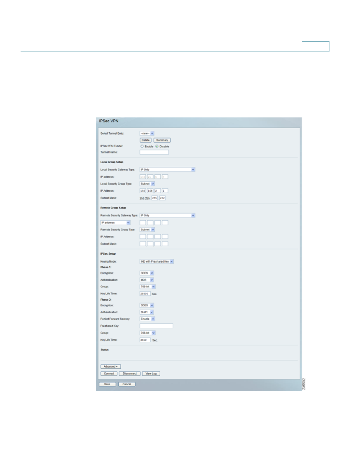
VPN > IPSec VPN
Use the VPN > IPSe c VPN window to create and configure a Virtual Private
Network (VPN) tunnel.
VPN > IPSec VPN
5
Cisco RVS4000 Security Router with VPN Administrato r G uide 60
Page 61

Setting Up and Configuring the Router
VPN
Select Tunnel Entry To create a new tunnel, select new. To configure an existing
tunnel, select it from the drop-down menu.
Delete Click this button to delete all settings for the selected tunnel.
Summary Clicking this button shows the settings and status of all enabled tunnels.
IPSec VPN Tunnel Check the Enable option to enable this tunnel.
Tunnel Name Enter a name for this tunnel, such as “Anaheim Office”.
Local Group Setup
Local Security Gateway Type This has two settings, IP Only and IP + Domain
Name (FQDN) Authentication.
• IP Only With this setting, the IP Address field automatically displays the
router’s WAN IP address.
5
• IP + Domain Name (FQDN) Authentication With this setting, the IP
Address field automatically displays the WAN IP address and domain name
for greater security. Enter an arbitrary domain name in the Domain Name
field.
Local Security Group Type Select the local LAN user(s) behind the router that can
use this VPN tunnel. This may be a single IP address or Sub-network. Notice that
the Local Security Group Type must match the other router’s Remote Security
Group Type.
IP Address Enter the IP address on the local network.
Subnet Mask If the Local Security Group Type is set to Subnet, enter the mask to
determine the IP addresses on the local network.
Remote Group Setup
Remote Security Gateway Type Select either IP Only or IP + Domain Name
(FQDN) Authentication. The setting should match the Local Security Gateway
Type for the VPN device at the other end of the tunnel.
• IP Only Choose this option to specify the remote device that can access
the tunnel. Then either select IP Address from the drop-down menu and
enter the remote gateway’s WAN IP address in the IP Address field, or
select IP by DNS Resolved from the drop-down menu and enter the remot e
gateway’s domain name in the Domain Name field.
• IP + Domain Name (FQDN) Authentication Choose this option to include
the IP address and a domain name for greater security. Enter an arbitrary
Cisco RVS4000 Security Router with VPN Administrato r G uide 61
Page 62

Setting Up and Configuring the Router
VPN
domain name in the Domain Name field. Then select either IP Address or
IP by DNS Resolved from the drop-down menu, and fill in the IP Address
field or Domain Name field.
Remote Security Group Type Select the remote LAN user(s) behind the remote
gateway who can use this VPN tunnel. This may be a single IP address or a Subnetwork. Note that the Remote Security Group Type must match the other router’s
Local Security Group Type.
IP Address Enter the IP address on the remote network.
Subnet Mask If the Remote Security Group Type is set to Subnet, enter the mask
to determine the IP addresses on the remote network.
IPSec Setup
Keying Mode The router supports both automatic and manual key management.
When choosing automatic key management, IKE (Internet Key Ex change) prot ocols
are used to negotiate key material for SA (Security Association). If manual key
management is selected, no key negotiation is needed. Basically, manual key
management is used in small static environments or for troubleshooting purposes.
Note that both sides must use the same Key Management method.
5
Phase 1
• Encryption The Encryption method determines the length of the key used
to encrypt/decrypt ESP packets. Only 3DES is supported. Notice that both
sides must use the same Encryption method.
• Authentication Authentication determines a method to authenticate the
ESP packets. Either MD5 or SHA1 may be selected. Notice that both sides
(VPN endpoints) must use the same Authentication method.
• MD5 A one-way hashing algorithm that produces a 128-bit digest.
• SHA1 A one-way hashing algorithm that produces a 160-bit digest.
• Group The Diffie-Hellman (DH) group to be used for key exchange. Select
the 768-bit (Group 1), 1024-bit (Group 2), or 1536-bit (Group 5) algorithm.
Group 5 provides the most security, Group 1 the least .
• Key Life Time This specifies the lifetime of the IKE-generated key. If the
time expires, a new key is re negotiated automatically. Enter a value from
300 to 100,000,000 seconds. The default is 28800 seconds.
Phase 2
Cisco RVS4000 Security Router with VPN Administrato r G uide 62
Page 63

Setting Up and Configuring the Router
VPN
• Encryption The Encryption method determines the length of the key used
to encrypt/decrypt ESP packets. Only 3DES is supported. Note that both
sides must use the same Encryption method.
• Authentication Authentication determines a method to authenticate the
ESP packets. Either MD5 or SHA1 may be selected. Note that both sides
(VPN endpoints) must use the same Authentication method.
• MD5 A one-way hashing algorithm that produces a 128-bit digest.
• SHA1 A one-way hashing algorithm that produces a 160-bit digest.
• Perfect Forward Secrecy If PFS is enabled, IKE Phase 2 negotiation
generates a new key material for IP traffic encryption and authentication.
Note that both sides must have this selected.
• Preshared Key IKE uses the Preshared Key field t o authenticat e the r emot e
IKE peer. Both character and hexadecimal values are acceptable in this
field; e.g., “My_@123” or “0x4d795f40313233”. Note that both sides must
use the same Preshared Key.
5
• Group The Diffie-Hellman (DH) group to be used for key exchange. Select
the 768-bit (Group 1), 1024-bit (Group 2), or 1536-bit (Group 5) algorithm.
Group 5 provides the most security, Group 1 the least .
• Key Life Time This specifies the lifetime of the IKE-generated key. If the
time expires, a new key is re negotiated automatically. Enter a value from
300 to 100,000,000 seconds. The default is 3600 seconds.
Status
Status Displays the connection status for the selected tunnel. The state is either
connected or disconnected.
Connect Click this button to establish a connection for the current VPN tunnel. If
you have made any changes, click Save first to apply your changes.
Disconnect Click this button to break a connection for the current VPN tunnel.
View Log Click this button to view the VPN log, which shows details of each tunnel
established.
Advanced Click this button to display these additional settings.
Cisco RVS4000 Security Router with VPN Administrato r G uide 63
Page 64

Setting Up and Configuring the Router
VPN
Aggressive Mode Specifies the type of Phase 1 exchange, Main mode or
Aggressive mode. Check the box to select Aggressive Mode or leave the box
unchecked (default) to select Main mode. Aggressive mode requires half of the
main mode messages to be exchanged in Phase 1 of the SA exchange. If network
security is preferred, select Main mode.
NetBios Broadcasts Check the box to enable NetBIOS traffic to pass through the
VPN tunnel. By default, the RVS4000 blocks these broadcasts.
Click Save to save your changes, or click Cancel to undo your changes.
VPN > VPN Client Accounts
Use this window to administer your VPN Client users. After you enter the
information at the top of the window, the information for the specified users
appears in the table. This feature is available with the Cisco QuickVPN client only.
The router supports up to five simultaneous Cisco QuickVPN sessions.
5
VPN > VPN Client Accounts
Username Enter the username. It can include any combination of keybo ard
characters.
Password Enter the password you would like to assign to this user.
Cisco RVS4000 Security Router with VPN Administrato r G uide 64
Page 65

Setting Up and Configuring the Router
VPN
Re-enter to Confirm Retype the password to ensure it has been entered
correctly.
Allow User to Change Password This option determines whether a user can
change his or her own password.
VPN Client List Table
No. Displays the user number.
Active When checked, the designated user can connect, otherwise the VPN client
account is disabled.
Username Displays the username.
Edit Allows editing of the username or password.
Remove Click this button to delete a user account.
5
Certificate Management
This section allows you to manage the certificate used for securing the
communication between the router and QuickVPN clients.
Generate Click this button to generate a new c e rtificate to replace the existing
certificate on the router.
Export for Admin Click this button to export the certificate for administrat or. When
prompted, indicate where to store your certificate. The default file name is
“RVS4000_Admin.pem” but you can use another name. The certificate for
administrator contains the private key and needs to be stored in a safe place as a
backup. If the router’s configuration is reset to the factory default, this certificate
can be imported and restored on the router.
Export for Client Click this button to exp ort the certificate for client. When
prompted, indicate where to store your certificate. The default file name is
“RVS4000_Client.pem” but you can use another name. For QuickVPN users to
securely connect to the router, this c ertificate needs to be placed in the install
directory of the QuickVPN client.
Import Click this button to import a certificate that was previously saved to a file
by using Export for Admin or Export for Client. Enter the file name in the field or
click Browse to locate the file on your computer, then click Import.
Certificate Last Generated or Imported This displays the date and time when a
certificate was last generated or imported.
Click Save to save your changes, or click Cancel to undo your changes.
Cisco RVS4000 Security Router with VPN Administrato r G uide 65
Page 66

Setting Up and Configuring the Router
VPN
VPN > VPN Passthrough
VPN > VPN Passthrough
IPSec PassThrough Internet Protocol Security (IPSec) is a suite of pr ot ocols used
to implement secure exchange of packets at the IP layer. IPSec Passthrough is
enabled by default to allow IPSec tunnels to pass through the router. To disable
IPSec Passthrough, select Disabled.
PPTP PassThrough Point-to-Point Tunneling Protocol (PPTP) allows the Point-to-
Point Proto col (PPP) to be tunneled through an IP network. PPTP Passthrough is
enabled by default. To disable it, select Disabled.
5
L2TP PassThrough Layer 2 Tunneling Protocol is the method used to enable
Point-to-Point sessions via the Internet on the Laye r 2 level. L2TP Passthrough is
enabled by default. To disable L2TP Passthrough, select Disabled.
Click Save to save your changes, or click Cancel to undo your changes.
Cisco RVS4000 Security Router with VPN Administrato r G uide 66
Page 67

Setting Up and Configuring the Router
QoS
QoS
You can use QoS (Quality of Service) to perform Bandwidth Management, by
either Rate Control or Priority. You can also configure QoS Trust Mode and the
DSCP settings.
QoS > Bandwidth Management
QoS > Bandwidth Management - Rate Control
5
Cisco RVS4000 Security Router with VPN Administrato r G uide 67
Page 68

Setting Up and Configuring the Router
QoS
Bandwidth
This section lets you specify the maximum bandwidth provided by the ISP on the
WAN interface, for both the upstream and downstream directions.
Bandwidth Management Type
Type The desired type of bandwidth management, either Rate Control or Priority
(default). Depending on your selection, the lower portion of the window displays
either the Rate Control section or the Priority section.
Rate Control
Service Select the service from the drop-down menu. If it does not contain the
service you need, click Service Management to add the service.
IP Enter the IP address or IP range you need to control. The default is zero which
includes all internal IP addresses.
5
Direction Select Upstream for outbound traffic or Downstream for inbound
traffic.
Mini. Rate Enter the minimum rate for the guaranteed bandwidth.
Max. Rate Enter the maximum rate for the guaranteed bandwidth.
Enable Check this box to enable this Rate Control Rule.
Add to list After a rule is set up, click this button to add it to the list. The list can
contain a maximum of 15 entries.
Delete selected application Click this button to delete a rule from the list.
Cisco RVS4000 Security Router with VPN Administrato r G uide 68
Page 69

Setting Up and Configuring the Router
QoS
Priority
QoS > Bandwidth Management - Priority
5
Service Select the service from the drop-down menu. If it does not contain the
service you need, click Service Management to add the service.
Direction Select Upstream for outbound traffic or Downstream for inbound
traffic from the drop-down menu.
Priority Select High, Medium, Normal, or Low priority for the service. The default
is Medium.
Enable Check this box to enable this Priority Rule.
Add to list After a rule is set up, click this button to add it to the list. The list can
contain a maximum of 15 entries.
Delete selected application Click this button to delete a rule from the list.
Click Save to save your changes, or click Cancel to undo your changes.
Cisco RVS4000 Security Router with VPN Administrato r G uide 69
Page 70

Setting Up and Configuring the Router
QoS
QoS > QoS Setup
Use the QoS Setup window to configure QoS Trust Mode for each LAN port.
QoS > QoS Setup
5
Port ID The number of the LAN port.
Trust Mo de Select either Port, CoS, or DSCP. The default is Port.
Defau lt CoS/ Po rt Pr io rity If Trust Mode is set to Port, select the port priority from
1 to 4 from the drop-down menu, where 4 is the highest priority. If Trust Mode is
set to CoS, select the default CoS priority from 0 to 7 from the drop-down menu.
CoS Setup
Priority The Co S priority from 0 to 7.
Queue Select the traffic forwarding queue, 1 to 4, to which the CoS priority is
mapped. Queue 4 has the highest priority.
Click Save to save your changes, or click Cancel to undo your changes.
Cisco RVS4000 Security Router with VPN Administrato r G uide 70
Page 71

Setting Up and Configuring the Router
QoS
QoS > DSCP Setup
QoS > DSCP Se tup
5
DSCP The Differentiated Services Code Point value in the incoming packet.
Queue Select the traffic forwarding queue, 1 to 4, to which the DSCP priority is
mapped. Queue 4 has the highest priority.
Restore Defaults Click this button to restore the default DSCP values.
Click Save to save your changes, or click Cancel to undo your changes.
Cisco RVS4000 Security Router with VPN Administrato r G uide 71
Page 72

Setting Up and Configuring the Router
Administration
Administration
Use the Administration menu to configure the system administration settings and
tools.
Administration > Management
Administration > Management
5
Router Access
Router Userlist Select the desired router user list.
Router Username Enter the user name here.
Router Password Enter the password.
Re-enter to Confirm Retype the password in this field.
SNMP
SNMP Select Enable if you wish to use SNMP. To use SNMP, you need SNMP
software on your PC.
System Name Ent er a suita ble name to identify this device. It will be displayed by
your SNMP software.
Cisco RVS4000 Security Router with VPN Administrato r G uide 72
Page 73

Setting Up and Configuring the Router
Administration
System Contact Enter contact information for the system.
System Location Enter the location of the system.
Read Community Enter the SNMP community name for SNMP “Get” commands.
Write Communit y Enter the SNMP community name for SNMP “Set” commands.
Trap Community Enter the SNMP community name for SNMP “Trap” commands.
Trap To Enter the IP Address of the SNMP Manager to which traps will be sent. If
desired, this may be left blank.
UPnP
You can use Universal Plug and Play (UPnP) to set up public services on your
network. When the UPnP function is enabled, Windows XP can add or delete
entries to the underlined UPnP Forwarding Table. Some Internet games require
enabling UPnP.
5
UPnP If you want to use UPnP, keep the default setting, Enable. Otherwise, select
Disable.
Cisco RVS4000 Security Router with VPN Administrato r G uide 73
Page 74

Setting Up and Configuring the Router
Administration
Administration > Log
Administration > Log
5
Log Setting
Log Level Select the log level(s) that the router should r ecord. Log levels and their
meanings are:
Log Levels
Level Severity Name Description
7 LOG_DEBUG Debug-level message
6 LOG_INFO Informational messages only
5 LOG_NOTICE Normal but significant condition
Cisco RVS4000 Security Router with VPN Administrato r G uide 74
Page 75

Setting Up and Configuring the Router
Administration
Log Levels
Level Severity Name Description
4 LOG_WARNING Warning conditions
3 LOG_ERR Error conditions
2 LOG_CRIT Critical conditions
1 LOG_ALERT Immediate action needed
0 LOG_EMERG System unusable
Outgoing Log Select Enable to cause all outgoing packets to be logged. You can
then click View Outgoing Table to display information on the outgoing packets
including Source IP, Destination IP, and Service/Port number.
5
Incoming Log Select Enable to cause all incoming packets to be logged. You can
then click View Incoming Table to display information on incoming packets
including Source IP, Destination IP, and Service/Port number.
Email Alerts
Email Alerts Select Enable to cause an email to be sent immediately if a DoS
(Denial of Service) attack is detected. If enabled, fill in the email address
information in the remaining fields in this section.
Denial of Service Thresholds Enter the number of DoS (Denial of Service) attacks
which need to be blocked by the built-in Firewall before an email alert is sent. The
minimum value is 20, and the maximum value is 100.
Log Queue Length The default is 50 entries. The router emails the log if there are
more than 50 entries.
Log Time Threshold The default is 10 minutes The router emails the log every 10
minutes.
SMTP Mail Server Enter the address (domain name) or IP address of the SMTP
(Simple Mail Transport Protocol) Server you use for outgoing email.
Email Address for Alert Logs Enter the email address the Log is to be sent to.
Return Email Address This address will appear as the Sender’s address in the
email.
Enable SMTP Authentication If your SMTP server requires Authentication, you
can enable it here, and enter the Username and Password.
Cisco RVS4000 Security Router with VPN Administrato r G uide 75
Page 76

Setting Up and Configuring the Router
Administration
Email Log Now Press this button to cause the log to be emailed immediately.
Syslog
Enable Syslog Check the box if you want to use this feature.
Syslog Server Enter the IP Address in this field when Enable Syslog is checked.
Local Log
Local Log Enable this if you want to see a log of all incoming and outgoing URLs or
IP addresses.
View Log Click this button when you wish to view the logs. A new window
appears with the log data.
5
Administration > Diagnostics
Administration > Diagnostics
Cisco RVS4000 Security Router with VPN Administrato r G uide 76
Page 77

Setting Up and Configuring the Router
Administration
Ping Test Parameters
Ping Target IP Enter the IP address or URL that you want to ping.
Ping Size Enter the size of the packet you want to use.
Number of Pings Enter the number of times you wish to ping the target device.
Ping Interval Enter the time period (milliseconds) between each ping.
Ping Timeout Enter the desired time period (milliseconds). If a response is not
received within the defined ping period, the ping is considered to have failed.
Start Test Click this button to begin the test. A new window appears with the test
results.
Ping Result Displays the Ping status.
5
Traceroute Test Parameters
Traceroute Target Enter the target IP address for the traceroute test.
Start Test Click this button to begin the test. A new window appears with the test
results.
Cable Diagnostics
Port Select the port number from the drop-down menu.
Pair Identifies a specific pair (A, B, C, or D) in the cable. Each cable consists of 8
pins (4 pairs).
Cable Length Displays the length of the cable in meters.
Status Displays the status of the pair.
Cisco RVS4000 Security Router with VPN Administrato r G uide 77
Page 78

Setting Up and Configuring the Router
Administration
Administration > Backup & Restore
Administration > Backup & Restore
To download a copy of the current configuration and store the file on your PC, click
Backup to start the download.
5
Restore Configuration
To restore a previously saved config file back to the router, enter the file name in
the field or click Browse to select the config file, then click Restore to upload the
config file.
Cisco RVS4000 Security Router with VPN Administrato r G uide 78
Page 79

Setting Up and Configuring the Router
Administration
Administration > Factory Default
Administration > Factory Default
5
Restore Factory Defaults Click this button to reset all configuration settings to
their factory default values. Any previously saved settings will be lost when the
default settings are restored. After clicking the button, another window appears.
Click OK to continue. Another window appears while the system reboots.
Cisco RVS4000 Security Router with VPN Administrato r G uide 79
Page 80

Setting Up and Configuring the Router
Administration
Administration > Reboot
Administration > Reboot
5
Reboot Click this button to reb oot the router. This operation does not cause the
router to lose any of its stored settings.
Administration > Firmware Upgrade
Administration > Firmware Upgrade
Use this page to upgrade the router by using firmware from Cisco.com. Step-bystep instructions are provided on the next page.
File Type in the name of the extracted firmware upgrade, or click Browse to locate
the file.
Start to Upgrade Once you have selected the appropriate file, click Start to
Upgrade and follow the on-screen instructions to upgrade your firmware.
Cisco RVS4000 Security Router with VPN Administrato r G uide 80
Page 81

Setting Up and Configuring the Router
Administration
STEP 1 Check the hardware version of the router by referring to the label on the bottom
panel. The PIDVID number includes the characters V01 (Version 1) or V02
(Version2).
STEP 2 To find the latest firmware for the router, go to www.cisco.com/go/software.
STEP 3 In the search box, enter: RVS4000, and then click Go.
STEP 4 In the Search Results, click the Download Software link for your rout er (usually the
first link).
STEP 5 Click the Small Business Router Firmware link.
STEP 6 Click the link for the latest release.
STEP 7 Click the Download Now button.
STEP 8 Continue through the screens to download the most recent firmware.
5
STEP 9 Extract the firmware file on your computer.
STEP 10 On the Administration > Firmware Upgrade page, click Browse, and then locate
your fil e.
STEP 11 Click Start to Up grade.
Cisco RVS4000 Security Router with VPN Administrato r G uide 81
Page 82

Setting Up and Configuring the Router
IPS
IPS
IPS > Configuration
IPS > Configuration
5
IPS Function Select Enable to enable or Disable to disable the IPS Function.
Anomaly Detection
HTTP Web attack signature is mat ched. HTTP request decoder decodes UTF-8 ( 1,
2, and 3 byte) code and normalize URI (according to those evasion methods
mentioned in whisker) before pattern match.
FTP FTP Bounce Detection and Inserting telnet opcodes into FTP command
stream Detection.
TELNET Normalization of Telnet negotiation strings.
RPC RP C rec ord fragging detection.
Signature Update Before upgrading the signature file, get the Router Intrusion
Prevention System (IPS) file from the Cisc o website. To find the file, go to
www.cisco.com/go/software (registration/login required), and search for RVS4000. After
downloading and extracting the file, enter the IPS Signature file name in the
Signature Update field, or click Browse to find the file. Then click Update and
follow the on-screen instructions.
Cisco RVS4000 Security Router with VPN Administrato r G uide 82
Page 83

Setting Up and Configuring the Router
IPS
IPS > P2P/IM
Peer To Peer
5
Peer to Peer
Peer-to-peer file sharing applications can be blocked (Block) or allowed (NonBlock). The preconfigured file sharing networks are GNUTELLA (EZPEER),
FASTTRACK, KURO, EDONKEY2000, BITTORRENT, DIRECTCONNECT, PIGO, and
WINMX.
Instant Messenger
Instant messaging applications can be blocked (Block) or allowed (Non-Block).
The preconfigured instant messaging applications are MSN, ICQ,
YAHOO_MESSENGER, IRC, ODIGO, REDIFF, GOOGLE_TALK, and IM_QQ.
Cisco RVS4000 Security Router with VPN Administrato r G uide 83
Page 84

Setting Up and Configuring the Router
IPS
IPS > Report
Provides a graphical representation of the level of network traffic and attacks
during the last twenty four hours.
Attacker
Displays the IP Address of attackers and the frequency (number of times) of the
attacks.
Attack Category
Displays the category (type) of attack and the frequency (number of times) of the
attacks.
5
Cisco RVS4000 Security Router with VPN Administrato r G uide 84
Page 85

Setting Up and Configuring the Router
IPS
IPS > Report
5
Cisco RVS4000 Security Router with VPN Administrato r G uide 85
Page 86

Setting Up and Configuring the Router
L2 Switch
IPS > Information
IPS > Information
5
L2 Switch
Signature Ve rsion Displays the version of the signature patterns in the router that
protects against malicious threats.
Last Time Upload This displays when the signature patterns in the router were
last updated.
Protect Scope Lists the types of attacks that the router’s IPS feature protects
against.
L2 Switch > Create VLAN
VLANs are logical subgroups of a Local Area Network (LAN) created via software
rather than defining a hardware solution. VLANs combine user stations and
network devices into a single domain regardless of the physical LAN segment to
which they are attached. VLANs allow network traffic to flow more efficiently
within subgroups. VLANs managed through software reduce the amount of time to
implement network changes.
VLANs have no minimum number of ports, and can be created per unit, per device,
per stack, or any other logical connection combination, as VLANs are software
based and not defined by physical attribu tes.
Cisco RVS4000 Security Router with VPN Administrato r G uide 86
Page 87

Setting Up and Configuring the Router
L2 Switch
VLANs function at layer 2. Since VLANs isolate traffic within the VLAN, a Layer 3
router is needed to allow traffic flow between VLANs. Layer 3 routers identify
segments and coordinate with VLANs.
VLANs are broadcast and multicast domains. Broadcast and multicast traffic is
transmitted only in the VLAN in which the traffic is generated.
The RVS4000 supports up to 4 VLANs, including the default VLAN.
L2 Switch > Create VLAN
5
VLAN ID The VLAN ID number. This can be any number from 2 to 3290, or from
3293 to 4094. (VLAN ID 1 is reser ved for the default VLAN, which is used for
untagged frames received on the interface. VLAN IDs 3291-3292 are reserved
and cannot be used.) To create a VLAN, enter the ID number and click Add VLAN.
VLAN ID Range To create multiple VLANs with a range of ID numbers, enter the
starting and ending ID numbers and click Add Range.
Delete Selected VLAN To delete a VLAN, select it form the VLAN list and click
Delete Selected VLAN.
Cisco RVS4000 Security Router with VPN Administrato r G uide 87
Page 88

Setting Up and Configuring the Router
L2 Switch
L2 Switch > VLAN Port Setting
L2 Switch > VLAN Port Setting
Port ID Displays the port number from 1 to 4.
Mode Select the mode of the port , either Trunk, Untagged, or Tagged. The
default is Untagged. In Trunk mode, incoming and outgoing frames can be either
tagged or untagged; incoming untagged frames are tagged with the default PVID
(Port VLAN ID). In Untagged mode, all incoming and outgoing frames are untagged.
In Tagged mode, all incoming and outgoing frames must be tagged; all untagged
frames are dropped.
5
PVID The Port VLAN ID (PVID) assigned to untagged frames received on the
interface. The default is 1. If the Mode is Tagged, the port receives only tagged
frames and so the port has no PVID.
Cisco RVS4000 Security Router with VPN Administrato r G uide 88
Page 89

Setting Up and Configuring the Router
L2 Switch
L2 Switch > VLAN Membership
L2 Switch > VLAN Membership
5
VLAN ID Select the VLAN whose membership you want to configure.
Description Enter a VLAN group name of up to 50 characters.
Function/Port table The top half of the table indicates each port’s current mode
(Untagged, Tagged, or Trunk). The lower half of the table is used to assign port
membership for the selected VLAN. The default for each port is Exclude (the port
is not a member of the VLAN). To make a port a memb er of the VLAN, select the
applicable mode(s). For example, if the port mode is Untagged, select Untagged; if
the mode is Tagged, select Tagged; if the mode is Trunk, select either Tagged or
Untagged.
Cisco RVS4000 Security Router with VPN Administrato r G uide 89
Page 90

Setting Up and Configuring the Router
L2 Switch
L2 Switch > RADIUS
L2 Switch > RADIUS
5
Mode Select Enabled or Disabled from the drop-down menu to enable or disable
RADIUS.
RADIUS IP Enter the Server IP address.
RADIUS UDP Port Enter the UDP port. The UDP port is used to verify the RADIUS
server authentication.
RADIUS Secret Enter the Key string for authenticating and encrypting all RADIUS
communications between the device and the RADIUS server. This key must match
the RADIUS server encryption key. If no host-specific value is specified, the global
value applies to each host.
Administration State Specifies the port authorization state. The possible field
values are:
• Auto The controlled port state is set by the Authentication method.
• Force Authorized The controlled port state is set to Force-Authorized
(forward traffic).
• Force Unauthorized The controlled port state is set to Force-Unauthorized
(discard traffic).
Port State Displays the state of the selected port.
Cisco RVS4000 Security Router with VPN Administrato r G uide 90
Page 91

Setting Up and Configuring the Router
L2 Switch
L2 Switch > Port Setting
L2 Switch > Port Setting
Port Displays the physical port number.
5
Link Displays the port duplex mode and speed. Full Duplex indicates that the
interface supports transmission between the device and its link partner in both
directions simultaneously. Half Duplex indicates that the interface supports
transmission between the device and the client in only one direction at a time.
Mode Select the port duplex mode and speed from the drop-down menu. Y ou can
also select Auto Negotiation, which is a protocol between two link partners that
enables a port to advertise its transmission rate, duplex mode and flow control
abilities to its partner.
Flow Control Displays the flow control status on the port. Operates when a port is
in Full duplex mode.
MaxFrame Displays the maximum frame size the port can receive and send.
Cisco RVS4000 Security Router with VPN Administrato r G uide 91
Page 92

Setting Up and Configuring the Router
L2 Switch
L2 Switch > Statistics
L2 Switch > Statistics
Statistics Overview
5
Tx Bytes Displays the number of Bytes transmitted from the selected port.
Tx Frames Displays the number of Frames transmitted from the selected port.
Rx Bytes Displays the number of Bytes received on the selected port.
Rx Frames Displays the number of Frames received on the selected port.
Tx Errors Displays the number of error packets transmitted from the selected
port.
Rx Errors Displays the number of error packets receive d from the selected port.
Cisco RVS4000 Security Router with VPN Administrato r G uide 92
Page 93

Setting Up and Configuring the Router
L2 Switch
L2 Switch > Port Mirroring
L2 Switch > Port Mirroring
5
Mirror Source Use this to enable or disable source port mirroring for each port on
the router. To enable source port mirroring on a port, check the box next to that
port. To disable s ource port mirroring on a port, leave the box unchecked. The
default is disabled.
Mirror Port Select the mirror destination p o rt from the drop-down menu.
Cisco RVS4000 Security Router with VPN Administrato r G uide 93
Page 94

Setting Up and Configuring the Router
L2 Switch
L2 Switch > RSTP
L2 Switch > RSTP
5
The RSTP (Rapid Spanning Tree Protocol) protocol prevents loops in the network
and dynamically reconfigures which physical links in a switch should forward
frames.
System Priority Enter the system priority from 0 to 61440 in increments of 4096.
Valid values are 0, 4096, 8192, 12288, 16384, 20480, 24576, 28672, 32768,
40960, 45056, 49152, 53248, 57344, and 61440. The lower the system priority,
the more likely the rout er is t o become the root in the Spanning Tree. The default is
32768.
Hello Time Enter a number from 1 to 10. The default is 2.
Max Age Enter a number from 6 to 40. The default is 20.
Forward Delay Enter a number from 4 to 30. The default is 15.
Force Version The default protocol version to use. Select Normal (use RSTP) or
Compatible (compatible with old STP). The default is Normal.
Protocol Enable Check this box to enable RSTP on the associated port. The
default is unchecked (RSTP disabled).
Edge Check this box to specify that the associated port is an edge port (end
station). Uncheck the box to specify that the associated port is a link (brid ge) to
another STP device. The default is checked (edge port).
Cisco RVS4000 Security Router with VPN Administrato r G uide 94
Page 95

Setting Up and Configuring the Router
Status
Path Cost The RSTP path cost for the designated ports. Enter a number from 1 to
200000000, or type the word auto (autogenerated path cost). The default is auto.
The default is auto.
Status
Status > Gateway
Status > Gateway
5
Firmware Version Displays the Gateway’s current firmware .
MAC Address Displays the Gateway MAC Address, as seen by your ISP.
Current Time Displays the time, based on the time zone you selected on the
Setup menu.
Internet Connection
Connection Type Displays the type of the connection.
Interface Displays the Gateway Internet Interface.
IP Address Displays the Gateway Internet IP Address.
Subnet Mask Displays the Subnet Mask for the IP address above.
Default Gateway Displays your ISP’s Gateway.
Cisco RVS4000 Security Router with VPN Administrato r G uide 95
Page 96

Setting Up and Configuring the Router
Status
DNS 1-2 Displays the DNS (Domain Name System) IP addresses currently used
by this Gateway.
IP Conntrack Click this button to display the IP Conntrack window.
IP Conntrack
The IP Conntrack (Connection Tracking) window displays information about TCP/
UDP connections, such as source and destination IP address and p o rt number
pairs (known as socket pairs), protocol types (TCP/UDP/ICMP), connection state
and timeouts. To see more information, click Next Page or Previous Page, or
select the page from the Go to Page drop-down menu. To see the latest
information, click Refresh. Click Close to return to the Status > Gateway window.
Status > Gateway > IP Conntrack
5
Cisco RVS4000 Security Router with VPN Administrato r G uide 96
Page 97

Setting Up and Configuring the Router
Status
Status > Local Netw ork
Status > Local Network
5
Current IP address System This shows the current system.
MAC Address The router MAC Address, as seen on your local, Ethernet network.
IP Address The Internet IP Address.
Subnet Mask The Subnet Mask for the IP addre ss above.
IPv6 Address The IPv6 IP address, if applicable.
DHCP Ser ver The status of the router’s DHCP server function.
Start IP Address The first address in the range of IP addresses used by the DHCP
Server.
End IP Address The final address in the range of IP addresses used by the DHCP
Server.
DHCP Client Table Click this button to open a window that displays the PCs that
use the router as a DHCP server. The DHCP Client Table window displays all
DHCP clients (PCs and other network devices) with this information: Client Names,
Interfaces, IP Addresses, MAC Addresses, and the length of time before their
assigned IP addresses expire.
ARP/RARP Table Click this but ton to open a window that displays the PCs that
use the router as an ARP/RARP server. The ARP/RARP Table window displays all
ARPs/RARPs (PCs and other network devices) with this information: IP addresses
and MAC addresses.
Cisco RVS4000 Security Router with VPN Administrato r G uide 97
Page 98

Using the VPN Setup Wizard
This chapter explains how to use the VPN Setup Wizard. It includes these sections:
• VPN Setup Wizard, page 98
• Before You Begin, page 98
• Running the VPN Setup Wizard, page 99
6
VPN Setup Wizard
Now you can configure a gateway-to-gateway VPN tunnel between two VPN
routers in a fast and efficient way by using the VPN Setup Wizard. The VPN Setup
Wizard works with users running Microsoft Windows 2000, XP, and Vista. This
document describes how to run the VPN Setup Wizard.
Before You Begin
The VPN Setup Wizard works with these routers:
• Cisco RVS4000 4-Port Gigabit Security Router with VPN
• Cisco WRVS4400N v1.1 Wireless-N 4-Port Gigabit Security Router with
• Cisco WRVS4400N v2 Wireless-N 4-Port Gigabit Security Router with VPN
Use these instructions to configure required data using the Web Administrator
Interface. For instructions on the Web Administrator Interface, see the
Administration Guide for your router.
VPN
Cisco RVS4000 Security Router with VPN Administrato r G uide 98
Page 99

Using the VPN Setup Wizard
Running the VPN Setup Wizard
STEP 1 Click Firewall > Basic Settings.
STEP 2 Enable Remote Management and enter 8080 in the Port field. Please note that you
cannot enter any other value if you want to use the VPN Wizard. Also, make sure
that HTTPS has been selected.
STEP 3 Click Save.
STEP 4 Click VPN > Summary and make sure the Tunnel(s) available are not zero.
STEP 5 Ensure that the LAN IP addresses of routers with VPN are in different subnets in
order for the VPN connection to work.
NOTE The VPN Setup Wizard assumes that no firewall/NAT device sits in front of the VPN
router .
6
Running the VPN Setup Wizard
STEP 1 Access the VPN Setup Wizard in one of two ways:
• If you have an RVS4000, WRVS4400N v1.1, or WRVS4400N v2 Installation
CD-ROM, insert it into your CD-ROM drive.
• Download the VPN Setup Wizard from the Cisco Support site for your
router .
STEP 2 Go to the Start menu and click Run. In the field provided, enter:
D:\VPN Setup Wizard.exe
STEP 3 When the Welcome window appears, click Start.
Cisco RVS4000 Security Router with VPN Administrato r G uide 99
Page 100

Using the VPN Setup Wizard
Running the VPN Setup Wizard
Welcome Window
6
Cisco RVS4000 Security Router with VPN Administrator Guide 100
 Loading...