

Page 1

4-Port SSL/IPSec
VPN Router
USER GUIDE
BUSINESS SERIES
Model: RVL200
Page 2
About This Guide
About This Guide
Icon Descriptions
While reading through the User Guide you may see
various icons that call attention to specific items. Below is
a description of these icons:
NOTE: This check mark indicates that there is
a note of interest and is something that you
should pay special attention to while using the
product.
WARNING: This exclamation point indicates
that there is a caution or warning and it is
something that could damage your property or
product.
WEB: This globe icon indicates a noteworthy
website address or e-mail address.
Open Source
This product may contain material licensed to you under
the GNU General Public License or other open-source
software licenses. Upon request, open-source software
source code is available at cost from Linksys for at least
three years from the product purchase date.
WEB: For detailed license terms and additional
information visit: www.linksys.com/gpl
Online Resources
Website addresses in this document are listed without
http:// in front of the address because most current web
browsers do not require it. If you use an older web browser,
you may have to add http:// in front of the web address.
Resource Website
Linksys www.linksys.com
Linksys International www.linksys.com/international
Glossary www.linksys.com/glossary
Network Security www.linksys.com/security
Copyright and Trademarks
Specifications are subject to change without notice.
Linksys is a registered trademark or trademark of Cisco
Systems, Inc. and/or its affiliates in the U.S. and certain
other countries. Copyright © 2007 Cisco Systems, Inc. All
rights reserved. Other brands and product names are
trademarks or registered trademarks of their respective
holders.
4-Port SSL/IPSec VPN Router
ii
Page 3

Table of Contents
Chapter 1: Introduction 1
Introduction to the Router. . . . . . . . . . . . . . . . . . . . . . . . . . . . . . . . . . . . . . . . 1
Introduction to Virtual Private Networks (VPNs) . . . . . . . . . . . . . . . . . . . . . . . . . . 1
VPN Router to VPN Router . . . . . . . . . . . . . . . . . . . . . . . . . . . . . . . . . . . . . 1
Computer (using SSL VPN client software) to VPN Router . . . . . . . . . . . . . . . . . 2
Chapter 2: Product Overview 3
Front Panel. . . . . . . . . . . . . . . . . . . . . . . . . . . . . . . . . . . . . . . . . . . . . . . . . . 3
Back Panel . . . . . . . . . . . . . . . . . . . . . . . . . . . . . . . . . . . . . . . . . . . . . . . . . . 3
Chapter 3: Installation 4
Physical Installation . . . . . . . . . . . . . . . . . . . . . . . . . . . . . . . . . . . . . . . . . . . . 4
Horizontal Placement . . . . . . . . . . . . . . . . . . . . . . . . . . . . . . . . . . . . . . . . 4
Vertical Placement . . . . . . . . . . . . . . . . . . . . . . . . . . . . . . . . . . . . . . . . . . 4
Wall-Mounting Placement . . . . . . . . . . . . . . . . . . . . . . . . . . . . . . . . . . . . . 4
Cable Connection . . . . . . . . . . . . . . . . . . . . . . . . . . . . . . . . . . . . . . . . . . . . . 5
Chapter 4: Advanced Conguration 6
Overview . . . . . . . . . . . . . . . . . . . . . . . . . . . . . . . . . . . . . . . . . . . . . . . . . . . 6
Before You Begin . . . . . . . . . . . . . . . . . . . . . . . . . . . . . . . . . . . . . . . . . . . . . . 6
Internet Explorer 6.0 or Higher . . . . . . . . . . . . . . . . . . . . . . . . . . . . . . . . . . 6
Netscape Communicator 8.0 or Higher . . . . . . . . . . . . . . . . . . . . . . . . . . . . . 6
How to Access the Web-Based Utility . . . . . . . . . . . . . . . . . . . . . . . . . . . . . . . . . 7
System Summary. . . . . . . . . . . . . . . . . . . . . . . . . . . . . . . . . . . . . . . . . . . . . . 8
System Information . . . . . . . . . . . . . . . . . . . . . . . . . . . . . . . . . . . . . . . . . 8
Port Statistics . . . . . . . . . . . . . . . . . . . . . . . . . . . . . . . . . . . . . . . . . . . . . 9
Network Setting Status . . . . . . . . . . . . . . . . . . . . . . . . . . . . . . . . . . . . . . . 9
Firewall Setting Status. . . . . . . . . . . . . . . . . . . . . . . . . . . . . . . . . . . . . . . . 9
IPSec VPN Setting Status . . . . . . . . . . . . . . . . . . . . . . . . . . . . . . . . . . . . . . 9
SSL VPN Setting Status . . . . . . . . . . . . . . . . . . . . . . . . . . . . . . . . . . . . . . . 9
Log Setting Status . . . . . . . . . . . . . . . . . . . . . . . . . . . . . . . . . . . . . . . . . . 9
Setup Tab > Network . . . . . . . . . . . . . . . . . . . . . . . . . . . . . . . . . . . . . . . . . . .10
Network . . . . . . . . . . . . . . . . . . . . . . . . . . . . . . . . . . . . . . . . . . . . . . . .10
Setup > Password . . . . . . . . . . . . . . . . . . . . . . . . . . . . . . . . . . . . . . . . . . . . .12
Password . . . . . . . . . . . . . . . . . . . . . . . . . . . . . . . . . . . . . . . . . . . . . . . .13
Setup > Time . . . . . . . . . . . . . . . . . . . . . . . . . . . . . . . . . . . . . . . . . . . . . . . .13
Time . . . . . . . . . . . . . . . . . . . . . . . . . . . . . . . . . . . . . . . . . . . . . . . . . . .13
Setup > DMZ Host . . . . . . . . . . . . . . . . . . . . . . . . . . . . . . . . . . . . . . . . . . . . .13
DMZ Host. . . . . . . . . . . . . . . . . . . . . . . . . . . . . . . . . . . . . . . . . . . . . . . .13
Setup Tab > Forwarding . . . . . . . . . . . . . . . . . . . . . . . . . . . . . . . . . . . . . . . . .14
Forwarding. . . . . . . . . . . . . . . . . . . . . . . . . . . . . . . . . . . . . . . . . . . . . . .14
Setup > UPnP . . . . . . . . . . . . . . . . . . . . . . . . . . . . . . . . . . . . . . . . . . . . . . . .15
UPnP. . . . . . . . . . . . . . . . . . . . . . . . . . . . . . . . . . . . . . . . . . . . . . . . . . .15
4-Port SSL/IPSec VPN Router
i
Page 4

Table of Contents
Setup > One-to-One NAT. . . . . . . . . . . . . . . . . . . . . . . . . . . . . . . . . . . . . . . . .16
One-to-One NAT . . . . . . . . . . . . . . . . . . . . . . . . . . . . . . . . . . . . . . . . . . .16
Setup > MAC Clone . . . . . . . . . . . . . . . . . . . . . . . . . . . . . . . . . . . . . . . . . . . .16
MAC Clone . . . . . . . . . . . . . . . . . . . . . . . . . . . . . . . . . . . . . . . . . . . . . . .17
Setup > DDNS. . . . . . . . . . . . . . . . . . . . . . . . . . . . . . . . . . . . . . . . . . . . . . . .17
DDNS . . . . . . . . . . . . . . . . . . . . . . . . . . . . . . . . . . . . . . . . . . . . . . . . . .17
Setup > Advanced Routing . . . . . . . . . . . . . . . . . . . . . . . . . . . . . . . . . . . . . . .17
Advanced Routing . . . . . . . . . . . . . . . . . . . . . . . . . . . . . . . . . . . . . . . . . .17
DHCP > Setup. . . . . . . . . . . . . . . . . . . . . . . . . . . . . . . . . . . . . . . . . . . . . . . .18
Setup . . . . . . . . . . . . . . . . . . . . . . . . . . . . . . . . . . . . . . . . . . . . . . . . . .19
DHCP > Status . . . . . . . . . . . . . . . . . . . . . . . . . . . . . . . . . . . . . . . . . . . . . . .20
Status . . . . . . . . . . . . . . . . . . . . . . . . . . . . . . . . . . . . . . . . . . . . . . . . . . . . .20
DHCP > Multiple VLANs . . . . . . . . . . . . . . . . . . . . . . . . . . . . . . . . . . . . . . . . .20
Multiple VLANs . . . . . . . . . . . . . . . . . . . . . . . . . . . . . . . . . . . . . . . . . . . .20
DHCP > Inter-VLAN Routing. . . . . . . . . . . . . . . . . . . . . . . . . . . . . . . . . . . . . . .21
Inter-VLAN Routing . . . . . . . . . . . . . . . . . . . . . . . . . . . . . . . . . . . . . . . . .21
System Management > Diagnostic . . . . . . . . . . . . . . . . . . . . . . . . . . . . . . . . . .21
Diagnostic . . . . . . . . . . . . . . . . . . . . . . . . . . . . . . . . . . . . . . . . . . . . . . .21
System Management > Factory Default . . . . . . . . . . . . . . . . . . . . . . . . . . . . . . .22
Factory Default . . . . . . . . . . . . . . . . . . . . . . . . . . . . . . . . . . . . . . . . . . . .22
System Management > Firmware Upgrade . . . . . . . . . . . . . . . . . . . . . . . . . . . . .22
Firmware Upgrade . . . . . . . . . . . . . . . . . . . . . . . . . . . . . . . . . . . . . . . . . .22
System Management > Restart . . . . . . . . . . . . . . . . . . . . . . . . . . . . . . . . . . . . .22
Restart . . . . . . . . . . . . . . . . . . . . . . . . . . . . . . . . . . . . . . . . . . . . . . . . .23
System Management > Setting Backup . . . . . . . . . . . . . . . . . . . . . . . . . . . . . . .23
Import Conguration File . . . . . . . . . . . . . . . . . . . . . . . . . . . . . . . . . . . . .23
Export Conguration File. . . . . . . . . . . . . . . . . . . . . . . . . . . . . . . . . . . . . .23
System Management > Port Mirroring . . . . . . . . . . . . . . . . . . . . . . . . . . . . . . . .23
Port Mirroring . . . . . . . . . . . . . . . . . . . . . . . . . . . . . . . . . . . . . . . . . . . . .23
System Management > IGMP Snooping . . . . . . . . . . . . . . . . . . . . . . . . . . . . . . .23
Port Management > Port Setup . . . . . . . . . . . . . . . . . . . . . . . . . . . . . . . . . . . .24
Basic Per Port Cong. . . . . . . . . . . . . . . . . . . . . . . . . . . . . . . . . . . . . . . . .24
Port Management > Port Status . . . . . . . . . . . . . . . . . . . . . . . . . . . . . . . . . . . .24
Port Status . . . . . . . . . . . . . . . . . . . . . . . . . . . . . . . . . . . . . . . . . . . . . . .24
Port Management > Create VLAN . . . . . . . . . . . . . . . . . . . . . . . . . . . . . . . . . . .25
Create VLAN . . . . . . . . . . . . . . . . . . . . . . . . . . . . . . . . . . . . . . . . . . . . . .25
Port Management > Port Setting. . . . . . . . . . . . . . . . . . . . . . . . . . . . . . . . . . . .25
Port Setting . . . . . . . . . . . . . . . . . . . . . . . . . . . . . . . . . . . . . . . . . . . . . .25
Port Management > VLAN Membership . . . . . . . . . . . . . . . . . . . . . . . . . . . . . . .25
VLAN Membership . . . . . . . . . . . . . . . . . . . . . . . . . . . . . . . . . . . . . . . . . .26
QoS > Bandwidth Management . . . . . . . . . . . . . . . . . . . . . . . . . . . . . . . . . . . .26
Bandwidth Management. . . . . . . . . . . . . . . . . . . . . . . . . . . . . . . . . . . . . .26
4-Port SSL/IPSec VPN Router
ii
Page 5

Table of Contents
QoS > QoS Setup. . . . . . . . . . . . . . . . . . . . . . . . . . . . . . . . . . . . . . . . . . . . . .28
QoS Setup . . . . . . . . . . . . . . . . . . . . . . . . . . . . . . . . . . . . . . . . . . . . . . .28
QoS > Queue Settings . . . . . . . . . . . . . . . . . . . . . . . . . . . . . . . . . . . . . . . . . .29
Queue Settings . . . . . . . . . . . . . . . . . . . . . . . . . . . . . . . . . . . . . . . . . . . .29
QoS > DSCP Settings . . . . . . . . . . . . . . . . . . . . . . . . . . . . . . . . . . . . . . . . . . .29
DSCP Settings . . . . . . . . . . . . . . . . . . . . . . . . . . . . . . . . . . . . . . . . . . . . .30
Firewall > General . . . . . . . . . . . . . . . . . . . . . . . . . . . . . . . . . . . . . . . . . . . . .30
General . . . . . . . . . . . . . . . . . . . . . . . . . . . . . . . . . . . . . . . . . . . . . . . . .30
Firewall > Access Rules . . . . . . . . . . . . . . . . . . . . . . . . . . . . . . . . . . . . . . . . . .31
Access Rules . . . . . . . . . . . . . . . . . . . . . . . . . . . . . . . . . . . . . . . . . . . . . .31
Add a New Access Rule . . . . . . . . . . . . . . . . . . . . . . . . . . . . . . . . . . . . . . .32
Firewall > Content Filter . . . . . . . . . . . . . . . . . . . . . . . . . . . . . . . . . . . . . . . . .33
Content Filter . . . . . . . . . . . . . . . . . . . . . . . . . . . . . . . . . . . . . . . . . . . . .33
IPSec VPN > Summary . . . . . . . . . . . . . . . . . . . . . . . . . . . . . . . . . . . . . . . . . .34
Summary . . . . . . . . . . . . . . . . . . . . . . . . . . . . . . . . . . . . . . . . . . . . . . . .35
IPSec VPN > Gateway to Gateway . . . . . . . . . . . . . . . . . . . . . . . . . . . . . . . . . . .35
Add a New Tunnel . . . . . . . . . . . . . . . . . . . . . . . . . . . . . . . . . . . . . . . . . .35
IPSec Setup . . . . . . . . . . . . . . . . . . . . . . . . . . . . . . . . . . . . . . . . . . . . . .38
IPSec VPN > VPN Pass Through . . . . . . . . . . . . . . . . . . . . . . . . . . . . . . . . . . . . .40
VPN Pass Through . . . . . . . . . . . . . . . . . . . . . . . . . . . . . . . . . . . . . . . . . .40
SSL VPN > Summary. . . . . . . . . . . . . . . . . . . . . . . . . . . . . . . . . . . . . . . . . . . .40
Summary . . . . . . . . . . . . . . . . . . . . . . . . . . . . . . . . . . . . . . . . . . . . . . . .40
SSL VPN > Certicate Management . . . . . . . . . . . . . . . . . . . . . . . . . . . . . . . . . .40
SSL VPN > User Management . . . . . . . . . . . . . . . . . . . . . . . . . . . . . . . . . . . . . .41
User Management . . . . . . . . . . . . . . . . . . . . . . . . . . . . . . . . . . . . . . . . . .41
SSL VPN > Virtual Passage . . . . . . . . . . . . . . . . . . . . . . . . . . . . . . . . . . . . . . . .42
Virtual Passage . . . . . . . . . . . . . . . . . . . . . . . . . . . . . . . . . . . . . . . . . . . .43
SNMP > Global Parameters . . . . . . . . . . . . . . . . . . . . . . . . . . . . . . . . . . . . . . .43
Global Parameters . . . . . . . . . . . . . . . . . . . . . . . . . . . . . . . . . . . . . . . . . .43
SNMP > Views. . . . . . . . . . . . . . . . . . . . . . . . . . . . . . . . . . . . . . . . . . . . . . . .44
Views . . . . . . . . . . . . . . . . . . . . . . . . . . . . . . . . . . . . . . . . . . . . . . . . . .44
SNMP > Group Prole. . . . . . . . . . . . . . . . . . . . . . . . . . . . . . . . . . . . . . . . . . .44
Group Prole . . . . . . . . . . . . . . . . . . . . . . . . . . . . . . . . . . . . . . . . . . . . .44
SNMP > Group Membership. . . . . . . . . . . . . . . . . . . . . . . . . . . . . . . . . . . . . . .45
Group Membership . . . . . . . . . . . . . . . . . . . . . . . . . . . . . . . . . . . . . . . . .45
SNMP > Communities. . . . . . . . . . . . . . . . . . . . . . . . . . . . . . . . . . . . . . . . . . .45
Communities . . . . . . . . . . . . . . . . . . . . . . . . . . . . . . . . . . . . . . . . . . . . .45
SNMP > Notication Recipient . . . . . . . . . . . . . . . . . . . . . . . . . . . . . . . . . . . . .46
Notication Recipient . . . . . . . . . . . . . . . . . . . . . . . . . . . . . . . . . . . . . . . .46
Log > System Log . . . . . . . . . . . . . . . . . . . . . . . . . . . . . . . . . . . . . . . . . . . . .47
System Log. . . . . . . . . . . . . . . . . . . . . . . . . . . . . . . . . . . . . . . . . . . . . . .47
Log > System Statistics . . . . . . . . . . . . . . . . . . . . . . . . . . . . . . . . . . . . . . . . . .48
4-Port SSL/IPSec VPN Router
iii
Page 6

Table of Contents
Wizard . . . . . . . . . . . . . . . . . . . . . . . . . . . . . . . . . . . . . . . . . . . . . . . . . . . .49
Basic Setup. . . . . . . . . . . . . . . . . . . . . . . . . . . . . . . . . . . . . . . . . . . . . . .49
Access Rule Setup . . . . . . . . . . . . . . . . . . . . . . . . . . . . . . . . . . . . . . . . . .51
Support. . . . . . . . . . . . . . . . . . . . . . . . . . . . . . . . . . . . . . . . . . . . . . . . . . . .53
Manual . . . . . . . . . . . . . . . . . . . . . . . . . . . . . . . . . . . . . . . . . . . . . . . . .53
Linksys Web Site . . . . . . . . . . . . . . . . . . . . . . . . . . . . . . . . . . . . . . . . . . .53
Logout . . . . . . . . . . . . . . . . . . . . . . . . . . . . . . . . . . . . . . . . . . . . . . . . . . . .53
Appendix A: Troubleshooting 55
Appendix B: Virtual Passage SSL VPN Client 5
Overview . . . . . . . . . . . . . . . . . . . . . . . . . . . . . . . . . . . . . . . . . . . . . . . . . . .56
Before You Begin (Windows OS) . . . . . . . . . . . . . . . . . . . . . . . . . . . . . . . . . . . .56
Internet Explorer 6.0 or Higher . . . . . . . . . . . . . . . . . . . . . . . . . . . . . . . . . .56
Netscape Communicator 8.0 or Higher . . . . . . . . . . . . . . . . . . . . . . . . . . . . .57
Make the SSL VPN Portal a Trusted Site (Windows OS) . . . . . . . . . . . . . . . . . . . . . .57
Login for the SSL VPN Portal (Windows OS) . . . . . . . . . . . . . . . . . . . . . . . . . . . . .58
Installation of the Virtual Passage Client (Windows OS) . . . . . . . . . . . . . . . . . . . . .58
Logout of the SSL VPN Portal (Windows OS) . . . . . . . . . . . . . . . . . . . . . . . . . . . .59
Windows Vista Usage . . . . . . . . . . . . . . . . . . . . . . . . . . . . . . . . . . . . . . . . . . .60
Login for the SSL VPN Portal (Mac OS X) . . . . . . . . . . . . . . . . . . . . . . . . . . . . . . .60
Installation of the Virtual Passage Client (Mac OS X). . . . . . . . . . . . . . . . . . . . . . . .60
Removal of the Virtual Passage Client (Mac OS X) . . . . . . . . . . . . . . . . . . . . . . . . .61
Before You Begin (Linux OS) . . . . . . . . . . . . . . . . . . . . . . . . . . . . . . . . . . . . . . .62
Login for the SSL VPN Portal (Linux OS). . . . . . . . . . . . . . . . . . . . . . . . . . . . . . . .62
Installation of the Virtual Passage Client (Linux OS) . . . . . . . . . . . . . . . . . . . . . . . .62
Removal of the Virtual Passage Client (Linux OS). . . . . . . . . . . . . . . . . . . . . . . . . .63
Appendix C: Bandwidth Management 64
6
4-Port SSL/IPSec VPN Router
Overview . . . . . . . . . . . . . . . . . . . . . . . . . . . . . . . . . . . . . . . . . . . . . . . . . . .64
Creation of New Services. . . . . . . . . . . . . . . . . . . . . . . . . . . . . . . . . . . . . . . . .64
Creation of New Bandwidth Management Rules. . . . . . . . . . . . . . . . . . . . . . . . . .65
Appendix D: Active Directory Server 66
Troubleshooting . . . . . . . . . . . . . . . . . . . . . . . . . . . . . . . . . . . . . . . . . . . . . .70
Appendix E: User for the Active Directory Server 71
Appendix F: Internet Authentication Service (IAS) Server 7
Appendix G: Lightweight Directory Access Protocol (LDAP) Server 7
3
9
iv
Page 7

Table of Contents
Appendix H: Deployment in an Existing Network 80
Overview . . . . . . . . . . . . . . . . . . . . . . . . . . . . . . . . . . . . . . . . . . . . . . . . . . .80
LAN-to-LAN Connection . . . . . . . . . . . . . . . . . . . . . . . . . . . . . . . . . . . . . . . . .80
WAN-to-LAN Connection. . . . . . . . . . . . . . . . . . . . . . . . . . . . . . . . . . . . . . . . .81
Appendix I: Gateway-to-Gateway VPN Tunnel 82
Overview . . . . . . . . . . . . . . . . . . . . . . . . . . . . . . . . . . . . . . . . . . . . . . . . . . .82
Before You Begin . . . . . . . . . . . . . . . . . . . . . . . . . . . . . . . . . . . . . . . . . . . . . .82
Conguration when the Remote Gateway Uses a Static IP Address . . . . . . . . . . . . . .82
Conguration of the RVL200. . . . . . . . . . . . . . . . . . . . . . . . . . . . . . . . . . . .82
Conguration of the RV082 . . . . . . . . . . . . . . . . . . . . . . . . . . . . . . . . . . . .83
Conguration of PC 1 and PC 2 . . . . . . . . . . . . . . . . . . . . . . . . . . . . . . . . . .83
Conguration when the Remote Gateway Uses a Dynamic IP Address. . . . . . . . . . . .84
Conguration of the RVL200. . . . . . . . . . . . . . . . . . . . . . . . . . . . . . . . . . . .84
Conguration of the RV082 . . . . . . . . . . . . . . . . . . . . . . . . . . . . . . . . . . . .84
Conguration of PC 1 and PC 2 . . . . . . . . . . . . . . . . . . . . . . . . . . . . . . . . . .85
Conguration when Both Gateways Use Dynamic IP Addresses . . . . . . . . . . . . . . . .85
Conguration of the RVL200. . . . . . . . . . . . . . . . . . . . . . . . . . . . . . . . . . . .85
Conguration of the RV082 . . . . . . . . . . . . . . . . . . . . . . . . . . . . . . . . . . . .86
Conguration of PC 1 and PC 2 . . . . . . . . . . . . . . . . . . . . . . . . . . . . . . . . . .86
Appendix J: IPSec NAT Traversal 87
Overview . . . . . . . . . . . . . . . . . . . . . . . . . . . . . . . . . . . . . . . . . . . . . . . . . . .87
Before You Begin . . . . . . . . . . . . . . . . . . . . . . . . . . . . . . . . . . . . . . . . . . . . . .87
Conguration of Scenario 1 . . . . . . . . . . . . . . . . . . . . . . . . . . . . . . . . . . . . . . .87
Conguration of Router A . . . . . . . . . . . . . . . . . . . . . . . . . . . . . . . . . . . . .87
Conguration of Router B . . . . . . . . . . . . . . . . . . . . . . . . . . . . . . . . . . . . .88
Conguration of Scenario 2 . . . . . . . . . . . . . . . . . . . . . . . . . . . . . . . . . . . . . . .89
Conguration of the One-to-One NAT Rules. . . . . . . . . . . . . . . . . . . . . . . . . .89
Conguration of Router B . . . . . . . . . . . . . . . . . . . . . . . . . . . . . . . . . . . . .89
Conguration of Router A . . . . . . . . . . . . . . . . . . . . . . . . . . . . . . . . . . . . .90
Appendix K: Conguration of Multiple Subnets 91
Overview . . . . . . . . . . . . . . . . . . . . . . . . . . . . . . . . . . . . . . . . . . . . . . . . . . .91
RVL200-to-RV042 Conguration . . . . . . . . . . . . . . . . . . . . . . . . . . . . . . . . . . . .91
RVL200 Conguration. . . . . . . . . . . . . . . . . . . . . . . . . . . . . . . . . . . . . . . .91
RV042 #1 Conguration. . . . . . . . . . . . . . . . . . . . . . . . . . . . . . . . . . . . . . .92
RV042 #2 Conguration. . . . . . . . . . . . . . . . . . . . . . . . . . . . . . . . . . . . . . .93
Appendix L: Multiple VLANs with Computers 94
Overview . . . . . . . . . . . . . . . . . . . . . . . . . . . . . . . . . . . . . . . . . . . . . . . . . . .94
RVL200-to-SRW2048 Conguration . . . . . . . . . . . . . . . . . . . . . . . . . . . . . . . . . .94
RVL200 Conguration. . . . . . . . . . . . . . . . . . . . . . . . . . . . . . . . . . . . . . . .94
SRW2048 Conguration . . . . . . . . . . . . . . . . . . . . . . . . . . . . . . . . . . . . . .95
4-Port SSL/IPSec VPN Router
v
Page 8

Table of Contents
Appendix M: Multiple VLANs and Subnets 96
Overview . . . . . . . . . . . . . . . . . . . . . . . . . . . . . . . . . . . . . . . . . . . . . . . . . . .96
RVL200 Conguration. . . . . . . . . . . . . . . . . . . . . . . . . . . . . . . . . . . . . . . . . . .96
Basic Instructions. . . . . . . . . . . . . . . . . . . . . . . . . . . . . . . . . . . . . . . . . . .96
Inter-VLAN Routing Option . . . . . . . . . . . . . . . . . . . . . . . . . . . . . . . . . . . .97
Appendix N: Access of Multiple VLANs over a SSL VPN Tunnel 98
Overview . . . . . . . . . . . . . . . . . . . . . . . . . . . . . . . . . . . . . . . . . . . . . . . . . . .98
SSL VPN Connection. . . . . . . . . . . . . . . . . . . . . . . . . . . . . . . . . . . . . . . . . . . .98
Static Route . . . . . . . . . . . . . . . . . . . . . . . . . . . . . . . . . . . . . . . . . . . . . . . . .98
Windows Operating System (OS) . . . . . . . . . . . . . . . . . . . . . . . . . . . . . . . . .98
Mac OS X . . . . . . . . . . . . . . . . . . . . . . . . . . . . . . . . . . . . . . . . . . . . . . . .98
Linux OS . . . . . . . . . . . . . . . . . . . . . . . . . . . . . . . . . . . . . . . . . . . . . . . .98
Appendix O: Firmware Upgrade 99
Overview . . . . . . . . . . . . . . . . . . . . . . . . . . . . . . . . . . . . . . . . . . . . . . . . . . .99
Before You Begin . . . . . . . . . . . . . . . . . . . . . . . . . . . . . . . . . . . . . . . . . . . . . .99
Internet Explorer 6.0 or Higher . . . . . . . . . . . . . . . . . . . . . . . . . . . . . . . . . .99
How to Access the Web-Based Utility . . . . . . . . . . . . . . . . . . . . . . . . . . . . . . . . .99
Upgrade the Firmware . . . . . . . . . . . . . . . . . . . . . . . . . . . . . . . . . . . . . . . . .100
Appendix P: Battery Replacement 101
Overview . . . . . . . . . . . . . . . . . . . . . . . . . . . . . . . . . . . . . . . . . . . . . . . . . . 101
Replace the Lithium Battery . . . . . . . . . . . . . . . . . . . . . . . . . . . . . . . . . . . . . .101
Appendix Q: Specications 102
Appendix S: Regulatory Information 10
FCC Statement . . . . . . . . . . . . . . . . . . . . . . . . . . . . . . . . . . . . . . . . . . . . . .104
Safety Notices. . . . . . . . . . . . . . . . . . . . . . . . . . . . . . . . . . . . . . . . . . . . . . . 104
Industry Canada Statement . . . . . . . . . . . . . . . . . . . . . . . . . . . . . . . . . . . . . . 104
Avis d’Industrie Canada. . . . . . . . . . . . . . . . . . . . . . . . . . . . . . . . . . . . . . 104
User Information for Consumer Products Covered by EU Directive 2002/96/EC on Waste
Electric and Electronic Equipment (WEEE) . . . . . . . . . . . . . . . . . . . . . . . . . . . . . 105
Appendix T: Contact Information 109
4
4-Port SSL/IPSec VPN Router
vi
Page 9

Chapter 1
Introduction
Chapter 1: Introduction
Introduction to the Router
Thank you for choosing the Linksys 4-Port SSL/IPSec
VPN Router. The Router is an advanced Internet-sharing
network solution for your small business needs. Like any
router, it lets multiple computers in your office share an
Internet connection. It features a built-in, 4-port, fullduplex, 10/100 Ethernet switch to connect four computers
directly, or you can connect more switches to create as
big a network as you need. If you have multiple routers in
your Local Area Network (LAN), you can use the Router’s
multiple subnet feature to support those routers.
The five Secure Sockets Layer (SSL) Virtual Private
Network (VPN) tunnels gives your mobile workers a
secure and easy way to stay connected. Additionally, an
IPSec (Internet Protocol Security), gateway-to-gateway
VPN tunnel facilitates branch office connectivity. As an
essential element of your business, the Router provides
security functions for authentication, encryption, and
firewall. Additional security features includes Denial of
Service (DoS) prevention and HTTPS management, while
the Quality of Service (QoS) features provide consistent
voice and video quality throughout your business.
Use the browser-based utility to configure settings and
run convenient wizards that will help you set up the
Router and its access rules.
Introduction to Virtual Private Networks (VPNs)
A VPN is a connection between two endpoints—a VPN
Router, for instance—in different networks that allows
private data to be sent securely over a shared or public
network, such as the Internet. This establishes a private
network that can send data securely between these two
locations or networks.
VPN Router supports two of the most popular VPN tunnel
types, SSL and IPSec.
There are two basic ways to create a VPN connection:
VPN Router to VPN Router
•
computer (using SSL VPN client software) to
•
VPN Router
NOTE: The 4-Port SSL/IPSec VPN Router does
not support IPSec VPN client software.
The VPN Router creates a “tunnel” or channel between two
endpoints, so that data transmissions between them are
secure. A computer with SSL or IPSec VPN client software
can be one of the two endpoints.
For an IPSec VPN tunnel, any computer with the built-in
IPSec Security Manager (Windows 2000 and XP) allows the
VPN Router to create a VPN tunnel using IPSec (Windows
Vista uses a similar utility). Other Windows operating
systems require additional, third-party VPN client software
applications that support IPSec to be installed.
For an SSL VPN tunnel, a computer can download the
Virtual Passage SSL VPN client software during first-time
connection to the SSL VPN Portal. (See “Appendix B: Virtual
Passage SSL VPN Client.”)
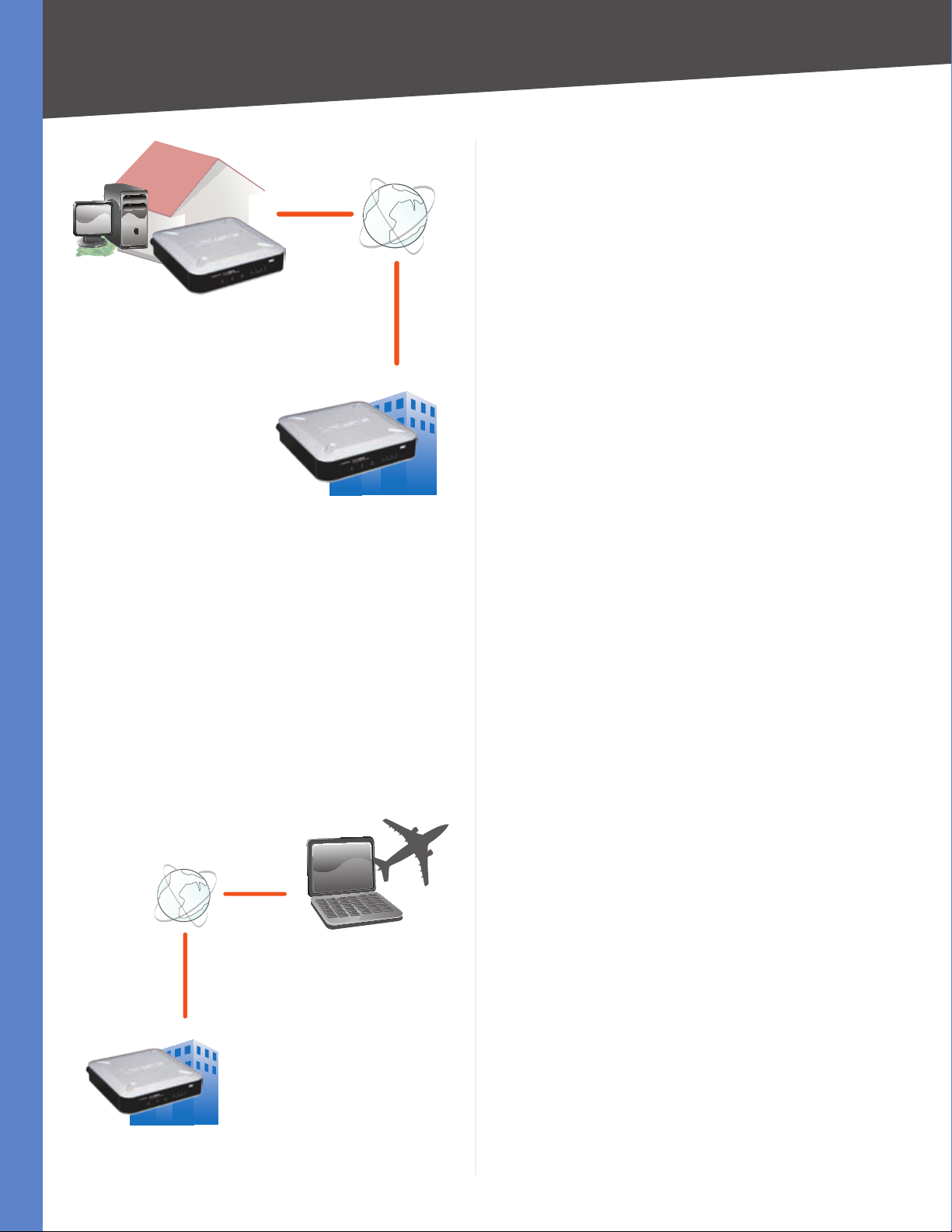
VPN Router to VPN Router
An example of a VPN Router-to-VPN Router VPN would
be as follows. At home, a telecommuter uses his VPN
Router for his always-on Internet connection. His Router
is configured with his office’s VPN settings. When he
connects to his office’s router, the two routers create a VPN
tunnel, encrypting and decrypting data. As VPNs utilize
the Internet, distance is not a factor. Using the VPN, the
telecommuter now has a secure connection to the central
office’s network, as if he were physically connected.
The private network is established by creating a “tunnel”. A
VPN tunnel connects the two computers or networks and
allows data to be transmitted over the Internet as if it were
still within those networks. A VPN tunnel uses industrystandard encryption and authentication techniques to
secure the data sent between the two networks.
Virtual Private Networking was created as a cost-effective
alternative to using a private, dedicated, leased line for a
private network. It can be used to create secure networks
linking a central office with branch offices, telecommuters,
and/or professionals on the road. The 4-Port SSL/IPSec
4-Port SSL/IPSec VPN Router
1
Page 10
Chapter 1
Introduction
Home
VPN Router
VPN Router
VPN Router to VPN Router
Internet
Central Office
Computer (using SSL VPN client software) to VPN Router
For additional information and instructions about
creating your own VPN, visit the Linksys website at
www.linksys.com.
The following is an example of a computer-to-VPN Router
VPN. In her hotel room, a traveling businesswoman
connects to her Internet Service Provider (ISP). Her
notebook computer has VPN client software that is
configured with her office’s VPN settings. She accesses the
VPN client software and connects to the VPN Router at the
central office. As VPNs utilize the Internet, distance is not
a factor. Using the VPN, the businesswoman now has a
secure connection to the central office’s network, as if she
were physically connected.
Off-Site
Internet
Notebook with VPN
Client Software
VPN
Router
Central Office
Computer to VPN Router
4-Port SSL/IPSec VPN Router
2
Page 11
Chapter 2
Product Overview
Chapter 2: Product Overview
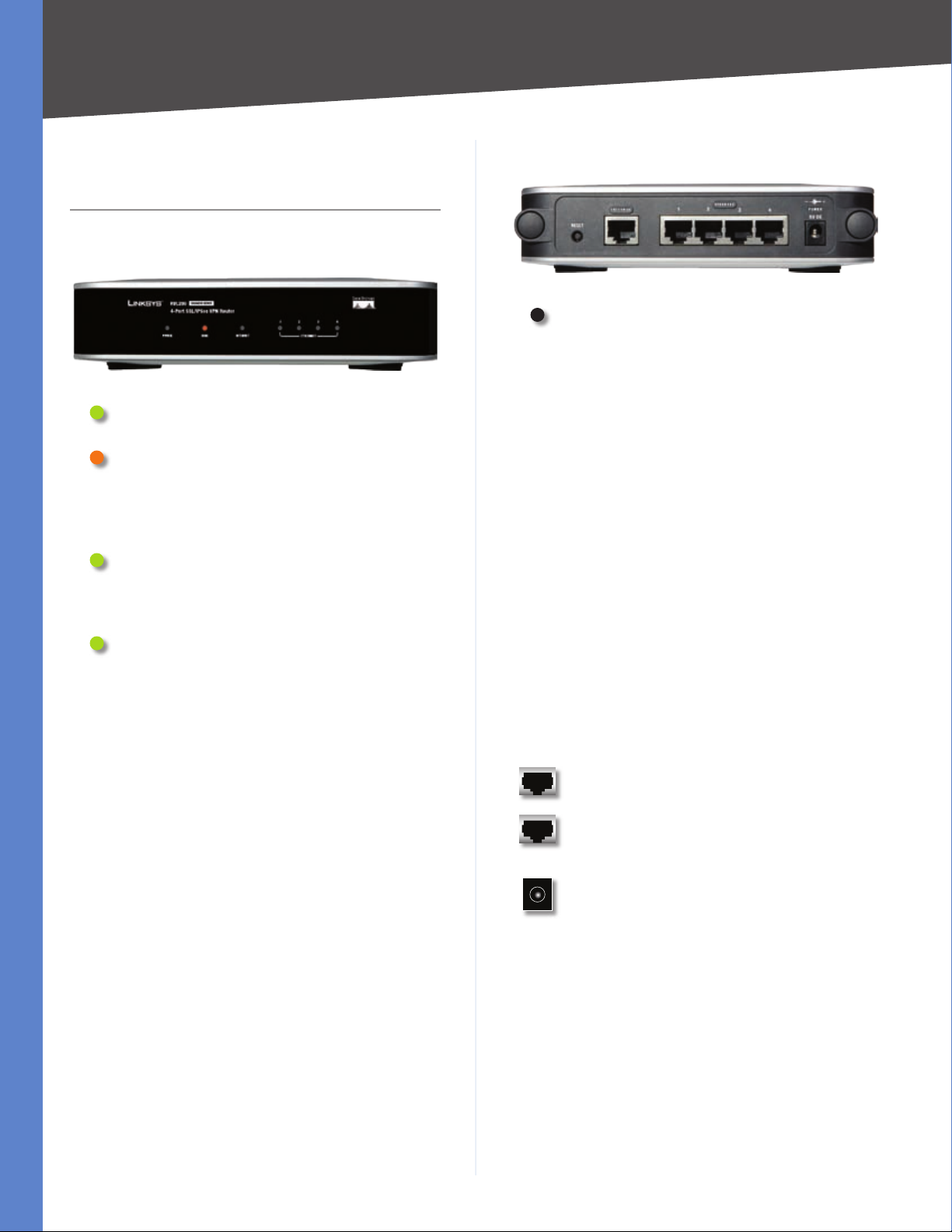
Front Panel
Power (Green) The Power LED lights up green
and stays on while the Router is powered on.
Diag (Orange) The Diag LED lights up when
the Router is not ready for use. During a warm
reset, it flashes slowly. During a reset to factory
defaults, it flashes quickly. The LED turns off
when the Router is ready for use.
Internet (Green) The Internet LED lights up
and stays on when there is a connection made
through the Internet port. It flashes to indicate
network activity over the Internet port.
Ethernet 1-4 (Green) These numbered LEDs,
corresponding with the numbered ports on the
Router’s back panel, serve two purposes. If the
LED is solidly lit, the Router is connected to a
device through that port. It flashes to indicate
network activity over that port.
Back Panel
Reset The Reset button can be used in one
of two ways, warm reset and reset to factory
defaults.
Warm Reset If the Router is having problems
•
connecting to the Internet, press and hold in
the Reset button for four seconds using the
tip of a pen. This is similar to pressing the
power button on your computer to reboot
it. The Diag LED will flash slowly during a
warm reset.
Reset to Factory Defaults If you are
•
experiencing extreme problems with
the Router and have tried all other
troubleshooting measures, press and hold
in the Reset button for ten seconds. This will
restore the factory defaults and clear all of
the Router’s custom settings. The Diag LED
will flash quickly during a reset to factory
defaults.
You can also reset the Router to factory
defaults using the System Management >
Factory Defaults screen of the Router’s
web-based utility.
Internet The Internet port is where you will
connect your cable or DSL Internet connection.
4-Port SSL/IPSec VPN Router
Ethernet 1, 2, 3, 4 These Ethernet ports (1, 2, 3,
4) connect the Router to wired computers and
other Ethernet network devices.
Power The Power port is where you connect
the power adapter.
3
Page 12
Chapter 3
64.4 mm
Installation
Chapter 3: Installation
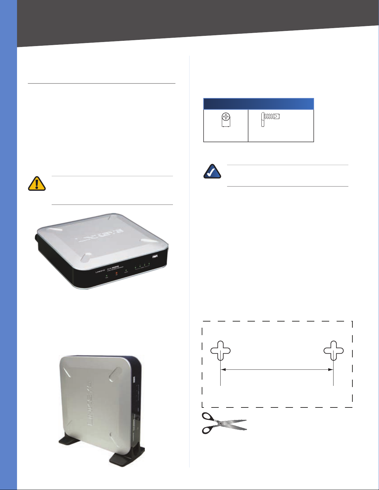
Physical Installation
There are three ways to place the Router. The first way is to
place it horizontally on a surface, so it sits on its four rubber
feet. The second way is to stand the Router vertically on a
surface. The third way is to mount it on a wall.
Horizontal Placement
The Router has four rubber feet on its bottom panel. Set
the Router on a flat surface near an electrical outlet.
WARNING: Do not place excessive weight
on top of the Router; too much weight could
damage it.
Wall-Mounting Placement
The Router has two wall-mount slots on its bottom. The
distance between the two slots is 64.4 mm (2.535 inches).
Two screws are needed to mount the Router.
Suggested Mounting Hardware
5.0-6.0 mm 1.6-2.0 mm
Note: Mounting hardware illustrations are not
†
true to scale.
NOTE: Linksys is not responsible for damages
incurred by insecure wall-mounting hardware.
Follow these instructions:
Determine where you want to mount the Router. Make
1.
sure that the wall you use is smooth, flat, dry, and
sturdy. Also make sure the location is within reach of
an electrical outlet.
3.0-3.8 mm
Vertical Placement
Line up the edges of the Router with the two stands.
1.
Insert the Router into the stands.
2.
Set the Router on a flat surface near an electrical
3.
outlet.
Drill two holes into the wall. Make sure the holes are
2.
64.4 mm (2.535 inches) apart.
Insert a screw into each hole and leave 5 mm
3.
(0.2 inches) of its head exposed.
Maneuver the Router so the wall-mount slots line up
4.
with the two screws.
Place the wall-mount slots over the screws and slide
5.
the Router down until the screws fit snugly into the
wall-mount slots.
Print this page at 100% size. Cut along
the dotted line, and place on the wall
to drill precise spacing.
4-Port SSL/IPSec VPN Router
Wall Mounting Template
4
Page 13
Chapter 3
Cable Connection
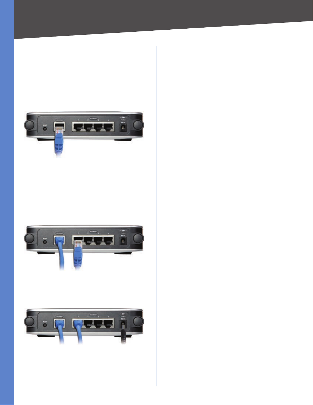
To connect network devices to the Router, follow these
instructions:
Before you begin, make sure that all of your hardware
1.
is powered off, including the Router, computers,
switches, and cable or DSL modem.
Connect your cable or DSL modem’s Ethernet cable to
2.
the Router’s Internet port.
Connect to the Internet Port
Installation
Power on the cable or DSL modem.
3.
Connect one end of an Ethernet network cable to
4.
one of the numbered ports on the back of the Router.
Connect the other end to an Ethernet port on a
network device, such as a computer or switch.
Repeat this step to connect more computers or other
network devices to the Router.
Connect to the Network Device
Connect the included power adapter to the Router’s
5.
Power port, and then plug the power adapter into an
electrical outlet.
Connect the Power
The Power LED on the front panel will light up as soon
6.
as the power adapter is connected properly.
Power on your computers and other network devices.
7.
4-Port SSL/IPSec VPN Router
5
Page 14
Chapter 4
Chapter 4: Advanced Configuration
Overview
For your convenience, use the Router’s web-based utility
to set it up and configure it. This chapter will explain all of
the functions in this utility.
These are the main tabs of the utility: System Summary,
Setup, DHCP, System Management, Port Management,
QoS, Firewall, IPSec VPN, SSL VPN, SNMP, Log, Wizard,
Support, and Logout. Additional tabs will be available
after you click one of the main tabs.
Before You Begin
The Router’s web-based utility and SSL VPN Portal
support Internet Explorer 6.0 (or higher) and Netscape
Communicator 8.0 (or higher) running in a Windows
environment.
To configure the SSL VPN software, your web browser must
have SSL, JavaScript, ActiveX, and cookies enabled (these
settings are enabled by default). If the settings are already
enabled, proceed to the next section, “How to Access the
Web-Based Utility”. If the settings are disabled, you should
enable them before configuring the Router. Proceed to
the instructions for your web browser.
Advanced Configuration
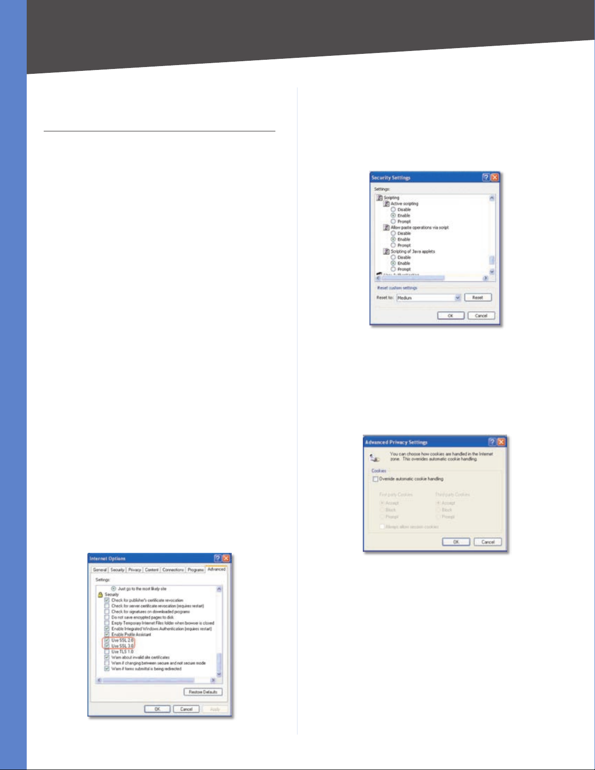
Click OK.
6.
Click the Security tab.
7.
Click Custom Level.
8.
Select Enable for Active scripting, Allow paste operations
9.
via script, and Scripting of Java applets.
Internet Explorer > Tools > Internet Options > Security
Click OK.
10.
Click the Privacy tab.
11.
Click Advanced.
12.
Deselect (remove the checkmark from) Override
13.
automatic cookie handling.
Internet Explorer 6.0 or Higher
Open Internet Explorer.
1.
Click Tools.
2.
Click Internet Options.
3.
Click the Advanced tab.
4.
Select Use SSL 2.0 and Use SSL 3.0.
5.
Internet Explorer > Tools > Internet Options > Advanced
Internet Explorer > Tools > Internet Options > Privacy
Click OK.
14.
Click OK again.
15.
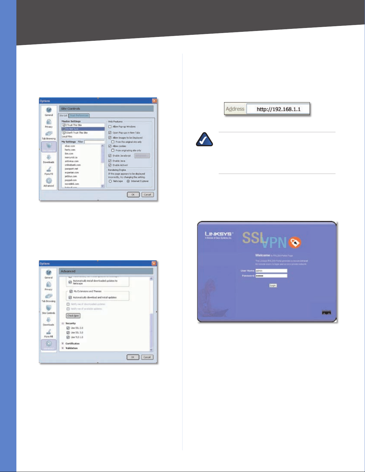
Netscape Communicator 8.0 or Higher
Open Netscape Communicator.
1.
Click Tools.
2.
Click Options.
3.
Click Site Controls.
4.
Click the Trust Preferences tab.
5.
In the Master Settings section, click I’m Not Sure.
6.
4-Port SSL/IPSec VPN Router
6
Page 15
Chapter 4
Select Allow cookies.
7.
Select Enable JavaScript.
8.
Click Advanced.
9.
Select Enable ActiveX.
10.
Netscape Communicator > Options > Site Controls > Web Features
Click OK.
11.
Advanced Configuration
How to Access the Web-Based Utility
For local access of the Router’s web-based utility,
1.
launch your web browser, and enter the Router’s
default IP address, 192.168.1.1, in the Address field.
Press the Enter key.
Address Bar
NOTE: If the Remote Management feature on
the Firewall > General screen has been enabled,
then users with administrative privileges can
remotely access the web-based utility. Use
https://<WAN IP address of the Router>.
A login screen prompts you for your User Name and
2.
Password. Enter admin in the User Name field, and
enter admin in the Password field. (You can change
the Password on the Setup > Password screen.) Then
click Login.
Under Options, click Advanced.
12.
Click Security.
13.
Select Use SSL 2.0 and Use SSL 3.0.
14.
Netscape Communicator > Options > Advanced > Security
Click OK.
15.
Login Screen
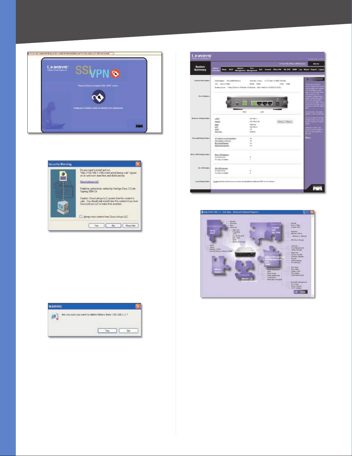
After you have logged in, you will be asked to install
3.
the Web Cache Cleaner application. This will prompt
any user of the Router to delete all temporary
Internet files, cookies, and browser history when the
user logs out or closes the web browser window.
(The ActiveX web cache control will be ignored by
web browsers that do not support ActiveX.)
Click the link to install the Web Cache Cleaner.
4-Port SSL/IPSec VPN Router
7
Page 16
Chapter 4
Click to Install the Web Cache Cleaner
On the Security Warning screen, click Yes.
4.
Advanced Configuration
Click Yes to Install
The Web Cache Cleaner will be installed in C:\\
5.
WINDOWS\Downloaded Program Files. Proceed to
the rest of this chapter for information about the webbased utility.
When you or another user logs out, a Warning screen
will appear. It will ask you to confirm that you want to
delete the History Item for the Router. Click Yes.
Click Yes to Delete History
System Summary
The first screen that appears is the System Summary
screen, which displays the Router’s current status and
settings. This information is read-only. Underlined text
is hyperlinked to related setup pages, so if you click a
hyperlink, the related setup screen will appear. On the
right-hand side of this screen and all other screens of the
utility is a link to the Site Map, which has links to all of the
utility’s tabs. Click Site Map to view the Site Map. Then,
click the desired tab.
System Summary
Site Map
System Information
Serial Number Displayed here is the serial number of the
Router.
Firmware version Displayed here is the current version
number of the firmware installed on the Router.
CPU Displayed here are the type and speed of the
processor installed on the Router.
DRAM Displayed here is the size of DRAM installed on
the Router’s motherboard.
Flash Displayed here is the size of flash memory installed
on the Router’s board.
4-Port SSL/IPSec VPN Router
8
Page 17
Chapter 4
Advanced Configuration
System Up Time This is the length of time in days, hours,
and minutes that the Router has been active. The current
time and date are also displayed.
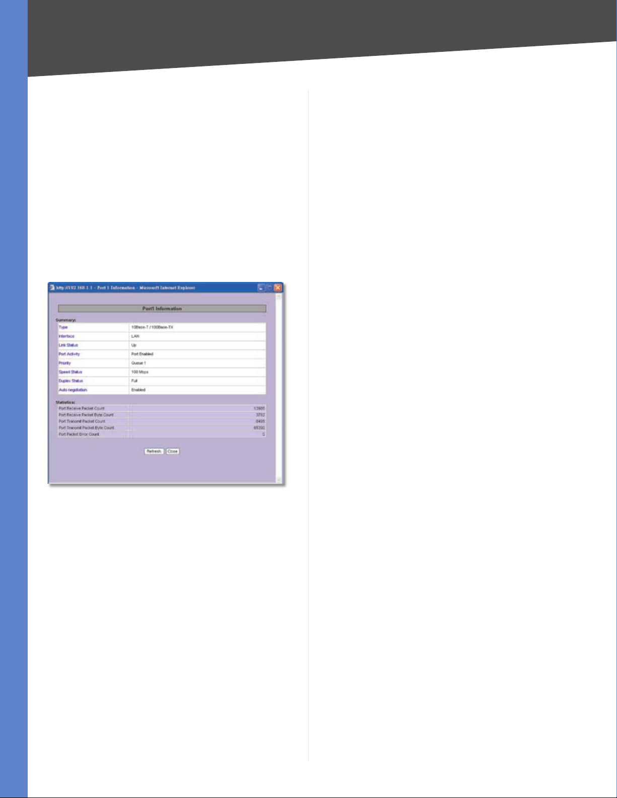
Port Statistics
Click any port on the Router’s rear panel image to see the
status of the selected port. If the port is disabled, it will
be red; if enabled, it will be black. If the port is connected,
it will be green. Information about the selected port will
appear in a separate window.
The port’s Summary table shows the settings of the
selected port, including Type, Interface, Link Status, Port
Activity, Priority, Speed Status, Duplex Status, and Auto
negotiation.
click Renew to update the DHCP Lease Time or get a new
IP address. If the WAN port is set to PPPoE or PPTP, two
buttons, Connect and Disconnect, will be available.
Mode It shows the Router’s Working Mode (Gateway or
Router), and it hyperlinks to the Dynamic Routing section
on the Advanced Routing screen of the Setup tab.
DNS It shows all DNS Server Addresses and hyperlinks to
the WAN Connection Type settings on the Network screen
of the Setup tab.
DDNS It shows the DDNS settings of the Router’s WAN
port and hyperlinks to the DDNS screen of the Setup tab.
DMZ Host It shows the DMZ Private IP Address and
hyperlinks to the DMZ Host screen of the Setup tab. The
default is Disabled.
Firewall Setting Status
SPI (Stateful Packet Inspection) It shows the status
(On/Off) of the SPI setting and hyperlinks to the General
screen of the Firewall tab.
DoS (Denial of Service) It shows the status (On/Off) of
the DoS setting and hyperlinks to the General screen of
the Firewall tab.
Port 1 Information
For the selected port, the statistics table shows this
information: number of packets received, number of
packet bytes received, number of packets transmitted,
number of packet bytes transmitted, and number of
packet errors.
To update the on-screen information, click Refresh. To
exit this screen, click Close.
Network Setting Status
LAN IP It shows the current LAN IP Address of the Router,
as seen by internal users on the network, and it hyperlinks
to the LAN Setting section on the Network screen of the
Setup tab.
WAN IP This shows the current WAN IP address of the
Router, as seen by external users on the Internet and
hyperlinks to the WAN Connection Type settings on the
Network screen of the Setup tab. If the port is set to Obtain
an IP automatically, two buttons, Release and Renew, will
be available. Click Release to release the IP address, and
Block WAN Request It shows the status (On/Off) of the
Block WAN Request setting and hyperlinks to the General
screen of the Firewall tab.
Remote Management It shows the status (On/Off) of
the Remote Management setting and hyperlinks to the
General screen of the Firewall tab.
IPSec VPN Setting Status
IPSec VPN Summary It hyperlinks to the Summary screen
of the IPSec VPN tab.
Tunnel(s) Used It shows the number of VPN tunnels
used.
Tunnel(s) Available It shows the number of VPN tunnels
available.
SSL VPN Setting Status
SSL VPN Summary It hyperlinks to the Summary screen
of the SSL VPN tab.
Tunnel(s) Used It shows the number of VPN tunnels
used.
Tunnel(s) Available It shows the number of VPN tunnels
available.
Log Setting Status
It hyperlinks to the System Log screen of the Log tab.
4-Port SSL/IPSec VPN Router
9
Page 18

Chapter 4
Advanced Configuration
If you have not set up the e-mail server on the Log tab,
the message, “E-mail cannot be sent because you have
not specified an outbound SMTP server address,” will be
displayed.
If you have set up the mail server but the log has not been
generated due to the Log Queue Length and Log Time
Threshold settings, the message, “E-mail settings have
been configured,” will be displayed.
If you have set up the e-mail server and the log has been
sent to the e-mail server, the message, “E-mail settings
have been configured and sent out normally,” will be
displayed.
If you have set up the e-mail server and the log cannot
be sent to the e-mail server, the message, “E-mail cannot
be sent out, probably use incorrect settings,” will be
displayed.
Setup Tab > Network
The Setup > Network screen shows all of the Router’s basic
setup functions. The Router can be used in most network
setups without changing any of the default values;
however, you may need to enter additional information in
order to connect to the Internet through an ISP (Internet
Service Provider) or broadband (DSL or cable) carrier. The
setup information is provided by your ISP.
LAN Setting
The MAC Address of the Router is displayed.
Device IP Address and Subnet Mask The default values
are 192.168.1.1 for the Router’s local IP address and
255.255.255.0 for the subnet mask.
Multiple Subnet Select this option to enable the Multiple
Subnet feature. Then click Add/Edit to create or modify
subnet(s). A new screen appears.
Create or Modify a Subnet
Setup > Network
Network
Host Name and Domain Name Enter a host and domain
name for the Router. Some ISPs require these names as
identification. You may have to check with your ISP to see
if your broadband Internet service has been configured
with a host and domain name. In most cases, you can
leave these fields blank.
LAN IP Address Enter the LAN IP address.
Subnet Mask Enter the subnet mask.
Click Add to List. Click Save Settings to save your changes,
or click Cancel Changes to undo them. Click Exit to return
to the Network screen.
If you want to modify a subnet you have created, select
it and Make changes.. Click Save Settings to save your
changes, or click Cancel Changes to undo them. Click
Exit to return to the Network screen.
If you want to delete a subnet you have created, select it
and click Delete selected subnet. Click Save Settings
to save your changes, or click Cancel Changes to undo
them. Click Exit to return to the Network screen.
WAN Connection Type
WAN
There are four connection types available: Obtain an IP
automatically, Static IP, PPPoE, and PPTP. Depending on
which connection type you select, you will see various
settings.
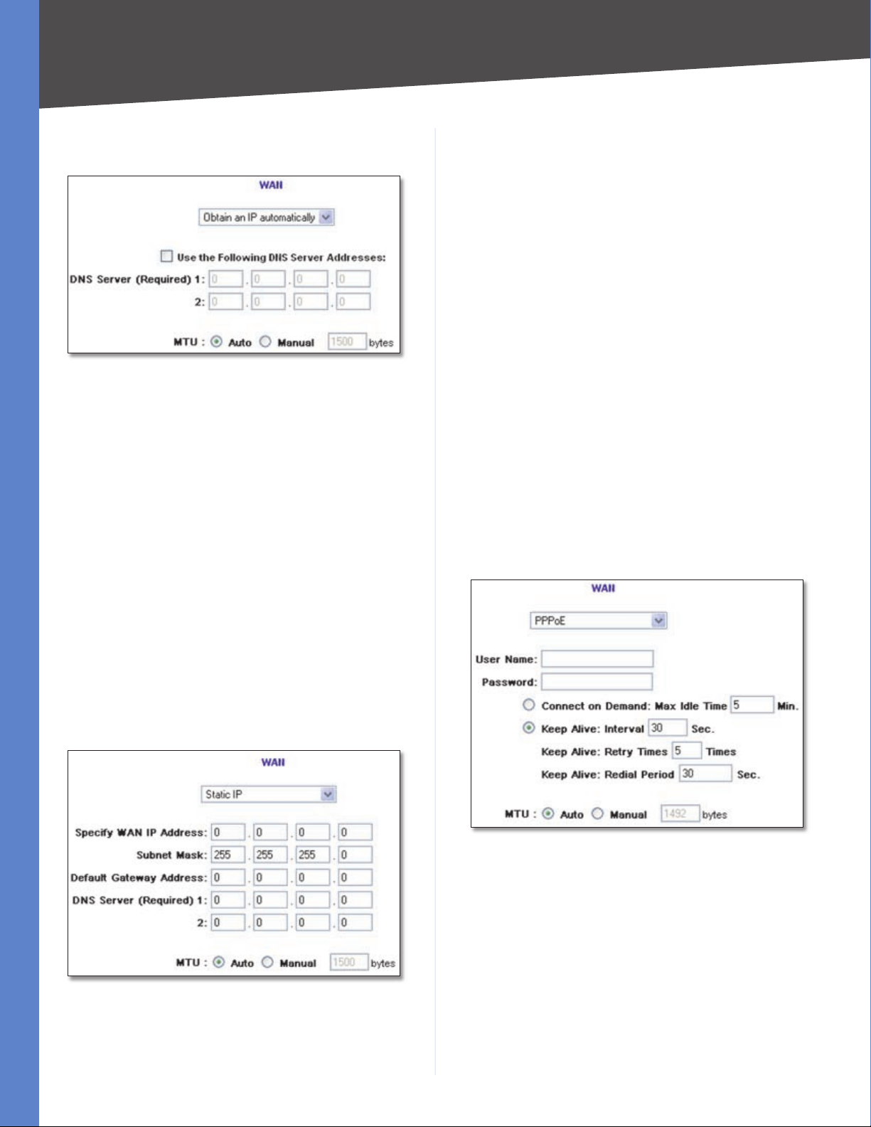
Obtain an IP Automatically
If your ISP automatically assigns an IP address, select
Obtain an IP automatically. (Most cable modem
4-Port SSL/IPSec VPN Router
10
Page 19
Chapter 4
Advanced Configuration
subscribers use this connection type.) Your ISP assigns
these values.
Obtain an IP Automatically
DNS Server (Required) 1/2 If you select Use the
Following DNS Server Addresses, enter your DNS server
IP address(es) (enter at least one). Multiple DNS server
IP settings are common. In most cases, the first available
DNS entry is used.
MTU The MTU (Maximum Transmission Unit) setting
specifies the largest packet size permitted for network
transmission. To manually set a value, select Manual and
enter the value desired in the field provided. You should
leave this value in the 1200 to 1500 range, and most DSL
users should use the value 1492. The default is Auto,
which allows the Router to select the best MTU for your
Internet connection.
Default Gateway Address Enter the IP address of the
default gateway.
DNS Server (Required) 1/2 If you select Use the
Following DNS Server Addresses, enter your DNS server
IP address(es) (enter at least one). Multiple DNS server
IP settings are common. In most cases, the first available
DNS entry is used.
MTU The MTU (Maximum Transmission Unit) setting
specifies the largest packet size permitted for network
transmission. To manually set a value, select Manual and
enter the value desired in the field provided. You should
leave this value in the 1200 to 1500 range, and most DSL
users should use the value 1492. The default is Auto,
which allows the Router to select the best MTU for your
Internet connection.
Click Save Settings to save your changes, or click Cancel
Changes to undo them.
PPPoE (Point-to-Point Protocol over Ethernet)
Some DSL-based Internet Service Providers (ISPs) use
PPPoE (Point-to-Point Protocol over Ethernet) to establish
Internet connections for end-users. If you use a DSL
line, check with your ISP to see if they use PPPoE, select
PPPoE.
Click Save Settings to save your changes, or click Cancel
Changes to undo them.
Static IP
If you are required to use a permanent IP address, select
Static IP.
Static IP
Specify WAN IP Address Enter the external IP address of
the Router.
Subnet Mask Enter the subnet mask of the Router.
PPPoE
User Name and Password Enter your account’s User
Name and Password. The maximum number of characters
is 60.
Connect on Demand If you select the Connect on
Demand option, the connection will be disconnected
after a specified period of inactivity (Max Idle Time). If you
have been disconnected due to inactivity, Connect on
Demand enables the Router to automatically re-establish
your connection as soon as you attempt to access the
Internet again. Enter the number of minutes you want to
have elapsed before your Internet access disconnects. The
default Max Idle Time is 5 minutes.
4-Port SSL/IPSec VPN Router
11
Page 20
Chapter 4
Advanced Configuration
Keep Alive: Interval If you select the Keep Alive option,
the Router will send keep-alive packets as often as you
specify. The default Interval is 30 seconds.
Keep Alive: Retry Times If you select the Keep Alive
option, the Router will send keep-alive packets as many
times as you specify. If the Router does not receive a
response from the ISP, then the Router will terminate the
connection and start sending PADI packets after the Redial
Period. The default Retry Times is 5 times.
Keep Alive: Redial Period If you select the Keep Alive
option, the Router will keep the connection alive by
sending out a few data packets periodically, so your ISP
thinks that the connection is still active. This option keeps
your connection active indefinitely, even when it sits idle.
The default Redial Period is 30 seconds.
MTU The MTU (Maximum Transmission Unit) setting
specifies the largest packet size permitted for network
transmission. To manually set a value, select Manual and
enter the value desired in the field provided. You should
leave this value in the 1200 to 1500 range, and most DSL
users should use the value 1492. The default is Auto,
which allows the Router to select the best MTU for your
Internet connection.
Click Save Settings to save your changes, or click Cancel
Changes to undo them.
Default Gateway Address Enter the IP address of the
default gateway.
DNS Server (Required) 1/2 If you select Use the
Following DNS Server Addresses, enter your DNS server
IP address(es) (enter at least one). Multiple DNS server
IP settings are common. In most cases, the first available
DNS entry is used.
User Name and Password Enter your account’s User
Name and Password. The maximum number of characters
is 60.
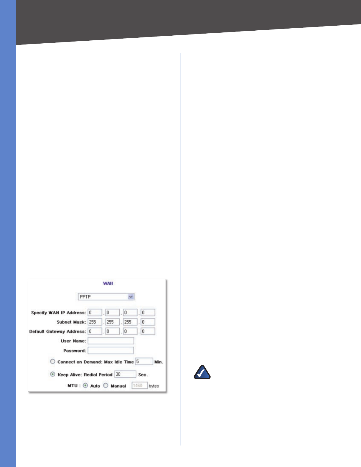
Connect on Demand If you select the Connect on
Demand option, the connection will be disconnected
after a specified period of inactivity (Max Idle Time). If you
have been disconnected due to inactivity, Connect on
Demand enables the Router to automatically re-establish
your connection as soon as you attempt to access the
Internet again. Enter the number of minutes you want to
have elapsed before your Internet access disconnects. The
default Max Idle Time is 5 minutes.
Keep Alive If you select the Keep Alive option, the Router
will keep the connection alive by sending out a few data
packets periodically, so your ISP thinks that the connection
is still active. This option keeps your connection active
indefinitely, even when it sits idle. The default Redial
Period is 30 seconds.
PPTP (Point-to-Point Tunneling Protocol)
Point to Point Tunneling Protocol (PPTP) is a service that
applies to connections in Europe and Israel only.
PPTP
Specify WAN IP Address Enter the external IP address of
the Router.
MTU The MTU (Maximum Transmission Unit) setting
specifies the largest packet size permitted for network
transmission. To manually set a value, select Manual and
enter the value desired in the field provided. You should
leave this value in the 1200 to 1500 range, and most DSL
users should use the value 1492. The default is Auto,
which allows the Router to select the best MTU for your
Internet connection.
Click Save Settings to save your changes, or click Cancel
Changes to undo them.
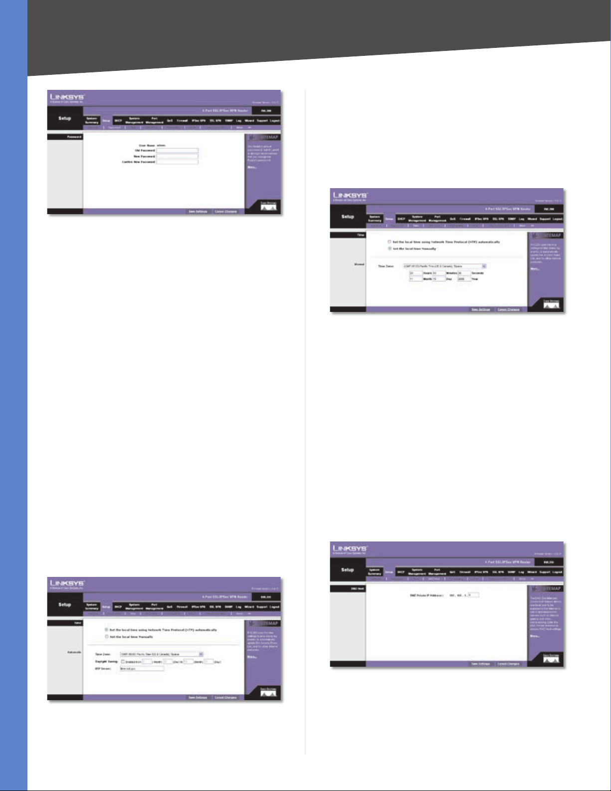
Setup > Password
The Router’s default User Name and Password is admin,
and Linksys strongly recommends that you change the
Router’s password from the default to a unique password.
NOTE: The password cannot be recovered if
it is lost or forgotten. If the password is lost or
forgotten, you have to reset the Router to its
factory default settings; this will remove all of
your configuration changes.
Subnet Mask Enter the subnet mask of the Router.
4-Port SSL/IPSec VPN Router
12
Page 21
Chapter 4
Setup > Password
Password
The User Name is admin; it cannot be changed.
Old Password Enter the old password. The default is
admin when you first power up the Router.
Advanced Configuration
Daylight Saving To use the daylight saving feature, select
Enabled. Enter the Month and Day of the start date, and
then enter the Month and Day of the end date.
NTP Server Enter the URL or IP address of the NTP server.
The default is time.nist.gov.
Manual
New Password Enter a new password for the Router. Your
password must have 20 or fewer characters and cannot
contain any spaces.
Confirm New Password Re-enter the new password to
confirm it.
Click Save Settings to save your change, or click Cancel
Changes to undo it.
Setup > Time
The Router uses the time settings to time stamp log events,
automatically apply the Access Rules and Content Filter,
and perform other activities for other internal purposes.
Time
To set the local time, select Set the local time using the
Network Time Protocol (NTP) automatically or Set the
local time Manually.
Automatic
Setup > Time > Manual
Time Zone Select your time zone (the default Time Zone
is Pacific Time).
Hours, Minutes, Seconds Enter the time.
Month, Day, Year Enter the date.
Click Save Settings to save your changes, or click Cancel
Changes to undo them.
Setup > DMZ Host
The DMZ (Demilitarized Zone) Host feature allows one
local user to be exposed to the Internet for use of a
special-purpose service such as Internet gaming or
videoconferencing. Although Port Range Forwarding can
only forward 10 ranges of ports maximum, DMZ hosting
forwards all the ports to one computer at the same time.
Setup > Time > Automatic
Time Zone Select your time zone (the default Time Zone
is Pacific Time).
4-Port SSL/IPSec VPN Router
Setup > DMZ Host
DMZ Host
DMZ Private IP Address Enter the local IP address of
the computer you want to expose. The default value of 0
deactivates the DMZ Host.
13
Page 22
Chapter 4
Advanced Configuration
Click Save Settings to save your change, or click Cancel
Changes to undo it.
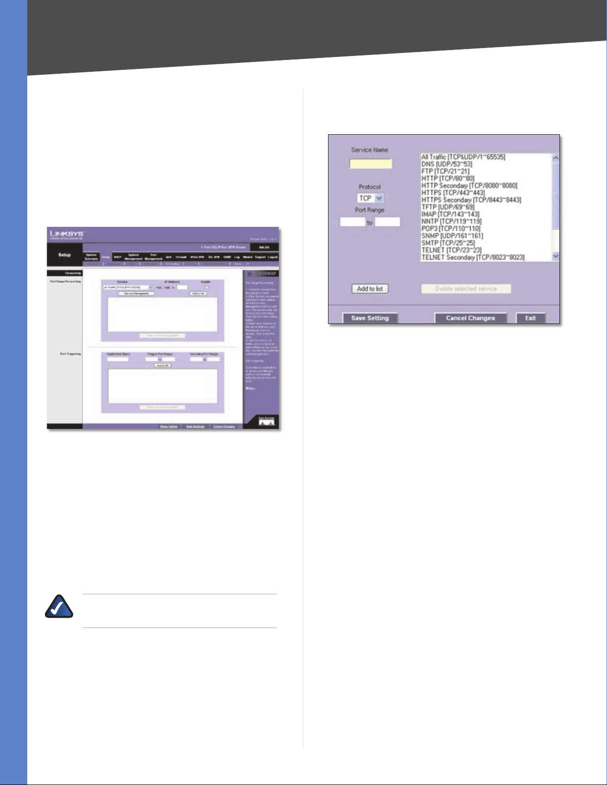
Setup Tab > Forwarding
The Forwarding screen allows you to set up port range
forwarding and port triggering applications. Port range
forwarding can be used to set up public services or other
specialized Internet applications on your network, while
port triggering can be used to set up triggered ranges and
forwarded ranges for Internet applications.
If the Service you need is not listed in the menu, click
Service Management to add the new service. The Service
Management screen appears.
Service Management
Service Name Enter a name.
Protocol Select the protocol it uses.
Setup > Forwarding
Forwarding
Port Range Forwarding
Port forwarding can be used to set up public services on
your network. When users from the Internet make certain
requests on your network, the Router can forward those
requests to computers equipped to handle the requests.
If, for example, you set the port number 80 (HTTP) to be
forwarded to IP address 192.168.1.2, then all HTTP requests
from outside users will be forwarded to 192.168.1.2.
NOTE: You must disable the Router’s DHCP
function to use port forwarding.
You may use this function to establish a web server or FTP
server via an IP gateway. Make sure that you enter a valid
IP address. (You may need to establish a static IP address
in order to properly run an Internet server.) For added
security, Internet users will be able to communicate with
the server, but they will not actually be connected. The
packets will simply be forwarded through the Router.
Service Select the Service you want.
Port Range Enter its range.
Click Add to List. Click Save Settings to save your changes,
or click Cancel Changes to undo them. Click Exit to return
to the Forwarding screen.
If you want to modify a service you have created, select it
and click Update this service. Make changes. Click Save
Settings to save your changes, or click Cancel Changes to
undo them. Click Exit to return to the Forwarding screen.
If you want to delete a service you have created, select it
and click Delete selected service. Click Save Settings
to save your changes, or click Cancel Changes to undo
them. Click Exit to return to the Forwarding screen.
IP Address Enter the IP address of the server that you
want the Internet users to access.
Enable Select Enable to enable this port range forwarding
entry.
Click Add to List, and configure as many entries as you
would like, up to a maximum of 30. To delete an entry,
select it and click Delete selected application.
Port Triggering
Port triggering allows the Router to watch outgoing data
for specific port numbers. The IP address of the computer
that sends the matching data is remembered by the
Router, so that when the requested data returns through
the Router, the data is pulled back to the proper computer
by way of IP address and port mapping rules.
4-Port SSL/IPSec VPN Router
14
Page 23
Chapter 4
Advanced Configuration
Some Internet applications or games use alternate ports
to communicate between the server and LAN host. When
you want to use these applications, enter the triggering
(outgoing) port and alternate incoming port in the
Port Triggering table. Then the Router will forward the
incoming packets to the LAN host.
Application Name Enter the name of the application.
Trigger Port Range Enter the starting and ending port
numbers of the trigger port range.
Incoming Port Range Enter the starting and ending port
numbers of the incoming port range.
Click Add to List, and configure as many entries as you
would like, up to a maximum of 30. To delete an entry,
select it and click Delete selected application.
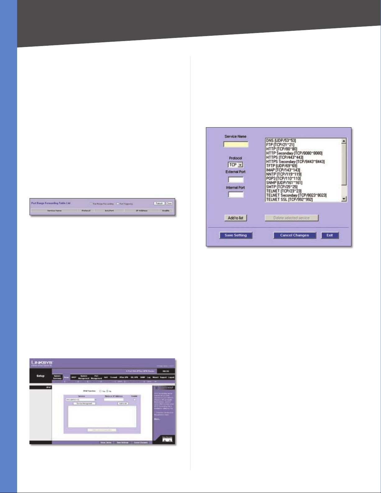
Click Show Tables to see the details of your entries. The
Port Range Forwarding Table List appears.
Port Range Forwarding Table List
Port Range Forwarding Select this option to view the
Port Range Forwarding entries.
UPnP
UPnP Function Select Yes to enable the UPnP function.
Otherwise, keep the default, No.
Service Select the Service you want.
If the Service you need is not listed in the menu, click
Service Management to add the new service. The Service
Management screen appears.
Port Triggering Select this option to view the Port
Triggering entries.
Click Refresh to update the on-screen information. Click
Close to exit this screen and return to the Forwarding
screen.
On the Forwarding screen, click Save Settings to save your
changes, or click Cancel Changes to undo them.
Setup > UPnP
Universal Plug and Play (UPnP) can be used to set up public
services on your network. When the UPnP function is
enabled, Windows XP can modify these entries via UPnP.
Setup > UPnP
Service Management
Service Name Enter a name.
Protocol Select the protocol it uses.
External Port Enter the external port number.
Internal Port Enter the internal port number.
Click Add to List. Click Save Settings to save your changes,
or click Cancel Changes to undo them. Click Exit to return
to the UPnP screen.
If you want to modify a service you have created, select it
and click Update this service. Make changes. Click Save
Settings to save your changes, or click Cancel Changes
to undo them. Click Exit to return to the UPnP screen.
If you want to delete a service you have created, select it
and click Delete selected service. Click Save Settings
to save your changes, or click Cancel Changes to undo
them. Click Exit to return to the UPnP screen.
Name or IP Address Enter the name or IP address of the
server that you want the Internet users to access.
Enable Select Enable to enable this UPnP entry.
Click Add to List, and configure as many entries as you
would like, up to a maximum of 30. To delete an entry,
select it and click Delete selected application.
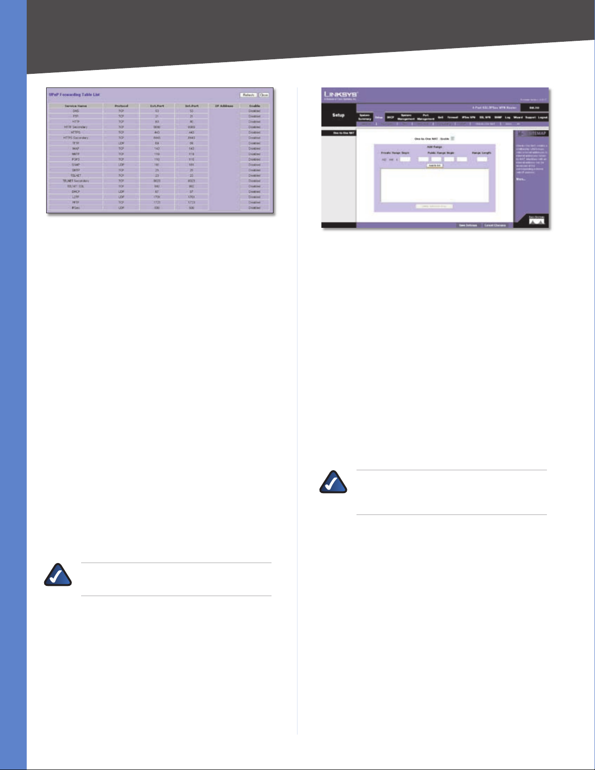
Click Show Tables to see the details of your entries. The
UPnP Forwarding Table List appears.
4-Port SSL/IPSec VPN Router
15
Page 24
Chapter 4
UPnP Forwarding Table List
Click Refresh to update the on-screen information. Click
Close to exit this screen and return to the UPnP screen.
On the UPnP screen, click Save Settings to save your
changes, or click Cancel Changes to undo them.
Setup > One-to-One NAT
One-to-One NAT (Network Address Translation) creates
a relationship that maps valid external IP addresses to
internal IP addresses hidden by NAT. A device with an
internal IP address may be accessed at the corresponding
external valid IP address.
To create this relationship, define internal and external
IP address ranges of equal length. Once the relationship
is defined, the device with the first internal IP address is
accessible at the first IP address in the external IP address
range, and so forth.
For example, you have a Local Area Network (LAN) for which
the ISP has assigned the IP address range of 209.19.28.16
to 209.19.28.31, with 209.19.28.16 used as the Wide Area
Network (WAN) or NAT public IP address of the Router.
The address range of 192.168.168.1 to 192.168.168.255 is
used for the devices on the LAN. With One-to-One NAT,
the devices with the internal IP addresses of 192.168.168.2
to 192.168.168.15 may be accessed at the corresponding
external IP addresses.
Advanced Configuration
Setup > One-to-One NAT
One-to-One NAT
One-to-One NAT Select Enable to use the One-to-One
NAT function.
Private Range Begin Enter the starting IP address of the
internal IP address range. This is the IP address of the first
device that
Public Range Begin Enter the starting IP address of the
public IP address range. This IP address is provided by the
ISP. (Do not include the Router’s WAN IP Address.)
Range Length Enter the number of IP addresses in the
range. The range length cannot exceed the number of
valid IP addresses. To map a single address, enter 1.
Click Add to List, and configure as many entries as you
would like, up to a maximum of 64. To delete an entry,
select it and click Delete selected range.
NOTE: One-to-One NAT affects how the firewall
functions work. Access to LAN devices from the
Internet is allowed unless access rules are set.
Click Save Settings to save your changes, or click Cancel
Changes to undo them.
NOTE: The Router’s WAN IP address should not
be included in the range you specify.
4-Port SSL/IPSec VPN Router
Setup > MAC Clone
Some ISPs require that you register a MAC address, which
is a 12-digit code assigned to a unique piece of hardware
for identification. The MAC Clone feature “clones” your
network adapter’s MAC address onto the Router, so you
don’t have to call your ISP to change the registered MAC
address to the Router’s MAC address.
For the WAN port, you can assign or clone a MAC address.
16
Page 25
Chapter 4
Advanced Configuration
User Name and Password Enter your DynDNS.org
account information.
Host Name Enter your host name in the three Host Name
fields. For example, if your host name were myhouse.
dyndns.org, then myhouse would go into the first field,
dyndns would go into the second field, and org would go
into the last field.
Click Save Settings, and the status of the DDNS function
will be updated.
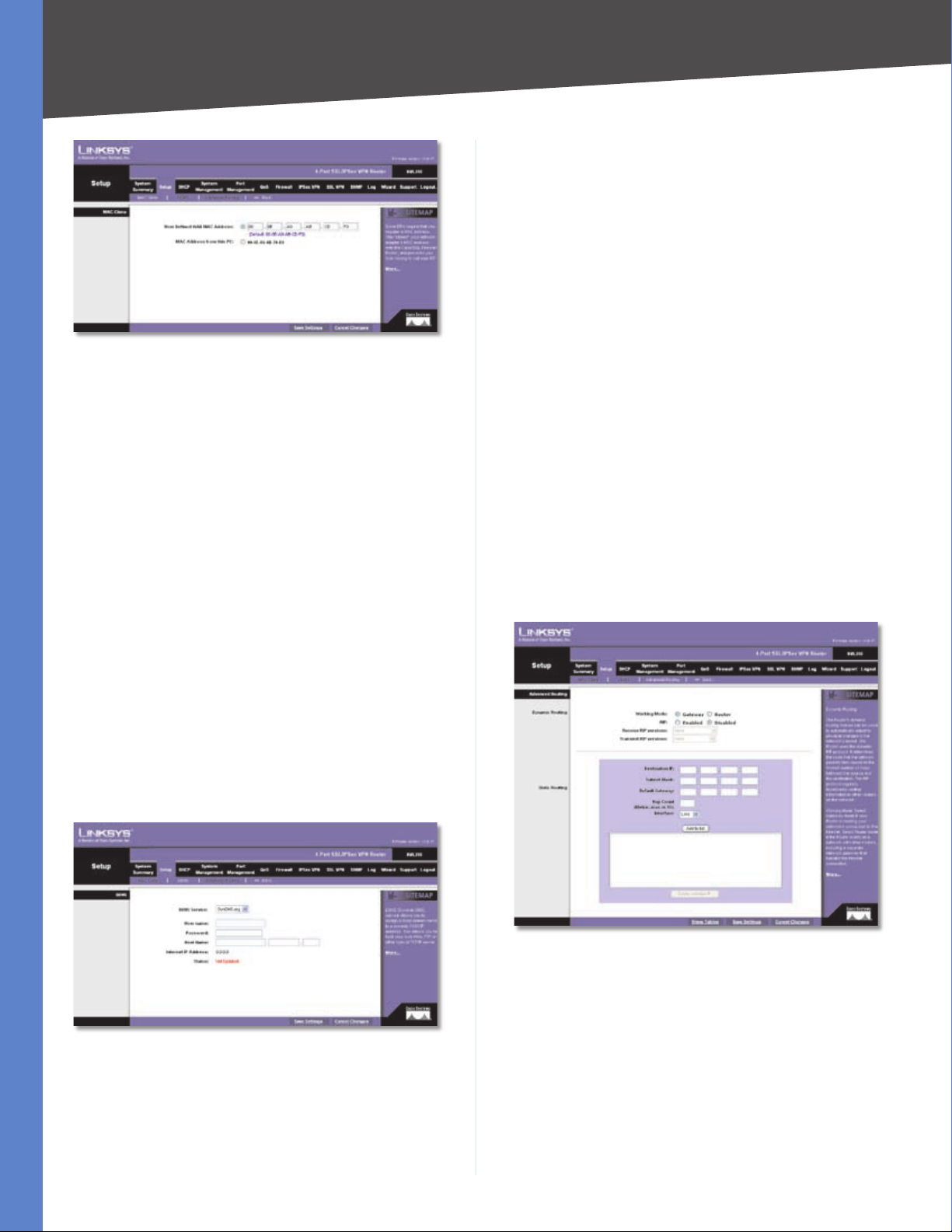
Setup > MAC Clone
MAC Clone
User Defined WAN MAC Address To manually clone a
MAC address, select User Defined WAN MAC Address,
and then enter the 12 digits of your adapter’s MAC
address.
MAC Address from this PC To clone the MAC address
of the computer you are currently using to configure the
Router, select MAC Address from this PC.
Click Save Settings to save your changes, or click Cancel
Changes to undo them.
Setup > DDNS
Dynamic Domain Name System (DDNS) service allows
you to assign a fixed domain name to a dynamic WAN IP
address, so you can host your own web, FTP or other type
of TCP/IP server in your LAN. The DDNS feature is disabled
by default.
Before configuring DDNS, visit www.dyndns.org and
register a domain name. (The DDNS service is provided by
DynDNS.org).
Internet IP Address The Router’s current Internet IP
address is displayed. Because it is dynamic, this will
change.
Status The status of the DDNS function is displayed. If
the status information indicates an error, make sure you
have correctly entered the information for your account
with your DDNS service.
Click Save Settings to save your changes, or click Cancel
Changes to undo them.
Setup > Advanced Routing
The Advanced Routing screen allows you to configure the
dynamic and static routing settings.
Setup > DDNS
DDNS
DDNS Service To enable DDNS, select DynDNS.org.
Otherwise, select Disable.
4-Port SSL/IPSec VPN Router
Setup > Advanced Routing
Advanced Routing
Dynamic Routing
The Router’s dynamic routing feature can be used, so
the Router will automatically adjust to physical changes
in the network’s layout. Using the dynamic RIP protocol,
the Router calculates the most efficient route for the
network’s data packets to travel between the source and
the destination, based upon the shortest paths. The RIP
protocol regularly broadcasts routing information to
17
Page 26

Chapter 4
Advanced Configuration
other routers on the network. It determines the route that
the network packets take based on the fewest number of
hops between the source and the destination.
Working Mode Select Gateway mode if the Router
is hosting your network’s connection to the Internet.
Select Router mode if the Router exists on a network
with other routers, including a separate network gateway
that handles the Internet connection. In Router mode,
any computer connected to the Router will not be able
to connect to the Internet unless you have another router
function as the gateway.
RIP (Routing Information Protocol) To use dynamic
routing for communication of network data, select
Enabled. Otherwise, keep the default, Disabled.
Receive RIP versions To use dynamic routing for
reception of network data, select the protocol you want:
None, RIPv1, RIPv2, or Both RIP v1 and v2.
Transmit RIP versions To use dynamic routing for
transmission of network data, select the protocol you want:
None, RIPv1, RIPv2 - Broadcast, or RIPv2 - Multicast.
Static Routing
If the Router is connected to more than one network or
there are multiple routers installed on your network, it
may be necessary to set up static routes. The static routing
function determines the path that data follows over your
network before and after it passes through the Router. You
can use static routing to allow different IP domain users to
access the Internet through the Router.
Static routing is a powerful feature that should be used
by advanced users only. In many cases, it is better to
use dynamic routing because it enables the Router to
automatically adjust to physical changes in the network’s
layout.
If you want to use static routing, the Router’s DHCP settings
must be disabled. Then add routing entries to the Static
Routing table. These entries tell the Router where to send
all incoming packets. All of your network routers should
direct the default route entry to the 4-Port SSL/IPSec VPN
Router.
Subnet Mask Enter the subnet mask used on the
destination LAN IP domain. For Class C IP domains, the
subnet mask is 255.255.255.0.
Default Gateway Enter the IP address of your network’s
gateway. If this Router is used to connect your network to
the Internet, then the gateway IP is the Router’s Internet
IP address. If you have another router handling your
network’s Internet connection, enter the IP address of that
router instead.
Hop Count Enter the appropriate value (maximum is 15).
This indicates the number of nodes that a data packet
passes through before reaching its destination. A node is
any device on the network, such as a switch, PC, or router.
Interface Select the appropriate interface. The Interface
tells you whether your network is on the LAN or the WAN
(the Internet). If you’re connecting to a sub-network, select
LAN. If you’re connecting to another network through the
Internet, select the appropriate WAN port option.
Click Add to List, and configure as many entries as you
would like, up to a maximum of 30. To delete an entry,
select it and click Delete selected IP.
Click Show Tables to see the details of your entries. Click
Save Settings to save your changes, or click Cancel
Changes to undo them.
DHCP > Setup
The Router can be used as a DHCP (Dynamic Host
Configuration Protocol) server on your network. A DHCP
server automatically assigns available IP addresses to
computers on your network. If you choose to enable the
DHCP server option, all of the computers on your LAN
must be set to obtain an IP address automatically from a
DHCP server. (By default, Windows computers are set to
obtain an IP automatically.)
If the Router’s DHCP server function is disabled, you have
to carefully configure the IP address, subnet mask, and
DNS settings of every computer on your network. Make
sure you do not assign the same IP address to different
computers.
NOTE: Static routing is an advanced feature.
Create these routes with care.
To create a static route entry, enter the following
information:
Destination IP Enter the network address of the remote
LAN segment. For a standard Class C IP domain, the
network address is the first three fields of the Destination
LAN IP, while the last field should be 0.
4-Port SSL/IPSec VPN Router
18
Page 27

Chapter 4
Advanced Configuration
Unknown MAC Address List
To add an IP address and MAC address set to the Static
IP list, select Enable, and then click Apply. To add all IP
addresses and MAC addresses to the Static IP list, click
Select All.
To update the on-screen information, click Refresh. To
exit this screen and return to the DHCP > Setup screen,
click Close.
Static IP Address Enter the static IP address. You can
enter 0.0.0.0 if you want the Router to assign a static IP
address to the device.
MAC Address Enter the MAC address of the device.
Name Enter a descriptive name for the device.
Enable Select Enable to assign the static IP address to
this device.
DHCP > Setup
Setup
Enable DHCP Server To use the Router as your network’s
DHCP server, select Enable DHCP Server. If you already
have a DHCP server on your network, remove the check
mark.
Dynamic IP
Client Lease Time The Client Lease Time is the amount
of time a network user will be allowed connection to the
Router with their current dynamic IP address. Enter the
amount of time, in minutes, that the user will be “leased”
this dynamic IP address. The range is 5-43,200 minutes.
The default is 1440 minutes.
Dynamic IP Range Start/End Enter a starting IP address
and ending IP address to create a range of available IP
addresses. The default range is 100-149. Enter a value for
the DHCP server to start with when issuing IP addresses.
This value must be 192.168.1. 2 or greater, because the
default IP address for the Router is 192.168.1.1.
Static IP
Click Add to List, and configure as many entries as you
would like, up to a maximum of 100. To delete an entry,
select it and click Delete selected Entry.
Block MAC address on the list with wrong IP address To
block traffic from devices with MAC addresses on the Static
IP list but using the wrong IP addresses, select this option.
It prevents users from changing device IP addresses
without your permission.
Block MAC address not on the list To block traffic from
devices using dynamic IP addresses, select this option. It
blocks all devices with MAC addresses not listed on the
Static IP list.
DNS
DNS Server You can assign DNS server(s) to the DHCP
clients so the Router will use the DNS server(s) for faster
access to functioning DNS server(s). Enter the IP address
of at least one DNS server.
WINS
WINS Server Windows Internet Naming Service (WINS)
is a service that resolves NetBIOS names to IP addresses.
WINS is assigned if the computer (DHCP client) requests
one. If you do not know the IP address of the WINS server,
keep the default, 0.0.0.0.
You can assign a static IP address to a specific device based
on its MAC address.
Show unknown MAC addresses Click Show unknown
MAC addresses to view all devices’ IP addresses and
corresponding MAC addresses. The Unknown MAC
Address List appears.
4-Port SSL/IPSec VPN Router
19
Page 28
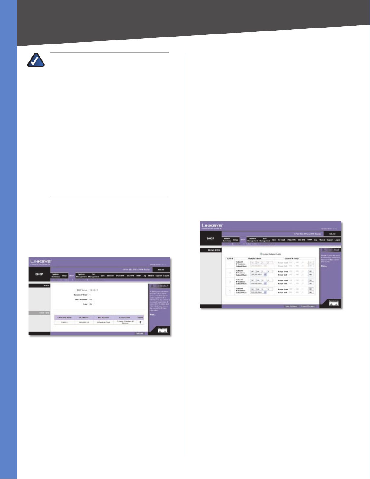
Chapter 4
Advanced Configuration
NOTE: To support NetBIOS for DHCP and Virtual
Passage clients, the Router uses two methods.
(Virtual Passage is an ActiveX-based VPN client
that provides full network connectivity for
Windows users. It allows remote access to the
Router’s network through a secure connection.)
First, when the DHCP and Virtual Passage clients
receive dynamic IP addresses from the Router,
it automatically includes the information of
the WINS server to support NetBIOS. Second,
if a user sets up a static IP address, then the IP
address, subnet mask, default gateway, and
DNS server settings must be configured on
the Internet Protocol (TCP/IP) screen of the
Windows operating system. Then the WINS IP
address must be configured on the advanced
TCP/IP screen. (For more information, refer to
Windows Help.)
Click Save Settings to save your changes, or click Cancel
Changes to undo them.
DHCP > Status
Client Table
For all network clients using the DHCP server, the Client
Table shows the current DHCP Client information:
Client Host Name This is the name assigned to a client
host.
IP Address It is the dynamic IP address assigned to a
client.
MAC Address This indicates the MAC address of a client.
Leased Time It displays the amount of time a network
user will be allowed connection to the Router with their
current dynamic IP address.
Delete Click the Trash Can icon to delete a DHCP client,
and the client host’s IP address will be released.
Click Refresh to refresh the on-screen information.
DHCP > Multiple VLANs
Use this screen to establish relationships between multiple
subnets and Virtual Local Area Networks (VLANs).
On the Status screen, view the status information for the
DHCP server and its clients.
DHCP > Status
Status
For the DHCP server, the following information is shown:
DHCP Server This is the IP address of the DHCP server.
Dynamic IP Used It shows the number of dynamic IP
addresses used.
DHCP Available This indicates the number of dynamic IP
addresses available.
Total It shows the total number of dynamic IP addresses
that can be assigned by the DHCP server.
DHCP > Multiple VLANs
Multiple VLANs
Enable Multiple VLANs Select this option to establish a
relationship between multiple subnets and VLANs. If you
enable this option and the multiple subnets and VLANs are
not enabled, then the Router will prompt you to configure
and enable the multiple subnets and VLANs.
VLAN ID The VLANs are configured on the Port
Management > Create VLAN screen (by default, all VLANs
created on this screen are part of the default subnet).
The VLAN IDs you assigned are displayed on the Multiple
VLANs screen.
Multiple Subnet Multiple subnets define different IP
networks using the subnet mask. They are created after
multiple VLANs are created. (If you want to change the
settings of VLAN 1, then use the Setup > Network screen
4-Port SSL/IPSec VPN Router
20
Page 29
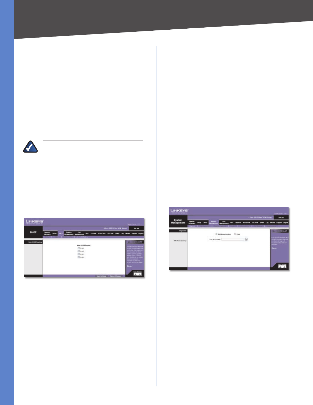
Chapter 4
Advanced Configuration
to configure the Device IP Address and Subnet Mask
settings.)
Subnet1-4 The subnet numbers are created according
•
to the VLAN numbers. (The multiple subnets can also
be configured on the Setup > Network screen.)
IP Address Enter an IP address.
•
Subnet Mask Select the appropriate subnet mask.
•
Dynamic IP Range When the IP Address and Subnet
Mask settings are configured, the range of IP addresses
is displayed. You can change the range of IP addresses
as long as the total number of IP addresses assigned by
DHCP is 253. The greater the number of multiple subnets,
the fewer the number of IP addresses assigned by DHCP.
NOTE: The Router’s built-in DHCP server can
assign up to 253 IP addresses.
Click Save Settings to save your changes, or click Cancel
Changes to undo them.
DHCP > Inter-VLAN Routing
To route packets between different VLANs, enable the
Multiple VLANs option on the Multiple VLANs screen, and
then select the VLANs on the Inter-VLAN Routing screen.
The Internet has a service called the Domain Name Service
(DNS), which allows users to enter an easily remembered
host name, such as www.linksys.com, instead of numerical
TCP/IP addresses to access Internet resources. The DNS
Name Lookup tool will return the numerical TCP/IP address
of a host name.
The Ping test bounces a packet off a machine on the
Internet back to the sender. This test shows if the Router
is able to contact the remote host. If users on the LAN
are having problems accessing services on the Internet,
try pinging the DNS server or other machine at the ISP’s
location. If this test is successful, try pinging devices
outside the ISP. This will show if the problem lies with the
ISP’s connection.
Diagnostic
DNS Name Lookup/Ping Select which tool you want
to use, DNS Name Lookup or Ping. Then proceed to the
appropriate instructions.
DNS Name Lookup
Before using this tool, make sure the IP address of the DNS
server is entered on the Setup > Network screen; otherwise,
this tool will not work.
DHCP > Inter-VLAN Routing
Inter-VLAN Routing
VLAN1-4 Select the VLANs that can route packets to each
other. For example, if you select VLAN1 and VLAN2, then
packets can be routed between VLAN1 and VLAN2, but
packets cannot be routed between VLAN3 and VLAN4.
Click Save Settings to save your changes, or click Cancel
Changes to undo them.
System Management > Diagnostic
The Router has two built-in tools, DNS Name Lookup
and Ping, which are used for troubleshooting network
problems.
4-Port SSL/IPSec VPN Router
System Management > Diagnostic > DNS Name Lookup
Look up the name Enter the host name, and click Go.
(Do not add the prefix http:// or else you will get an error
message.) The Router will then query the DNS server and
display the result at the bottom of the screen.
Ping
Before using this tool make sure you know the device or
host’s IP address. If you do not know it, use the Router’s
DNS Name Lookup tool to find the IP address.
21
Page 30
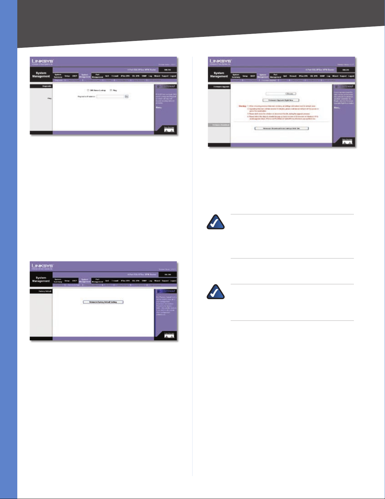
Chapter 4
System Management > Diagnostic > Ping
Advanced Configuration
Ping host or IP address Enter the IP address of the device
being pinged, and click Go. The test will take a few seconds
to complete. When completed, the Router will display the
results at the bottom of the screen. The results include
this information: status; number of packets transmitted,
received, or lost; and round trip time (minimum, maximum,
and average).
System Management > Factory Default
Use this screen to clear all of your configuration information
and restore the Router to its factory default settings. Only
use this feature if you wish to discard all the settings and
preferences that you have configured.
System Management > Firmware Upgrade
Firmware Upgrade
To download the firmware, refer to the Firmware Download
instructions. If you have already downloaded the firmware
onto your computer, then click the Browse button to look
for the file.
NOTE: If you are using Internet Explorer on
Windows XP, disable the pop-up blocking
function before you upgrade the Router’s
firmware. Refer to “Appendix O: Firmware
Upgrade” for more information.
Firmware Upgrade Right Now After you have selected
the file, click Firmware Upgrade Right Now.
NOTE: The Router will take approximately ten
minutes to upgrade its firmware. During this
process, do not power off the Router or press
the Reset button.
Firmware Download
System Management > Factory Default
Factory Default
Return to Factory Default Setting Click Return to
Factory Default Setting if you want to restore the Router
to its factory default settings. After clicking the button, a
confirmation screen appears. Click OK to continue.
System Management > Firmware Upgrade
You can use this feature to upgrade the Router’s firmware
to the latest version.
4-Port SSL/IPSec VPN Router
Firmware Download from Linksys Web Site If you need
to download the latest version of the Router’s firmware,
click Firmware Download from Linksys Web Site. The
Support page of the Linksys website appears.
Select 4-Port SSL/IPSec VPN Router from the dropdown menu, and choose the firmware from the available
options. After downloading the firmware file, extract it
on your computer. Then follow the Firmware Upgrade
instructions.
For more details, refer to “Appendix O: Firmware
Upgrade”.
System Management > Restart
If you need to restart the Router, Linksys recommends that
you use the Restart tool on this screen. When you restart
22
Page 31

Chapter 4
Advanced Configuration
from the Restart screen, then the Router will send out your
log file before it is reset.
System Management > Restart
Restart
Restart Router Click Restart Router to restart the
Router.
System Management > Setting Backup
This screen allows you to make a backup file of your
preferences file for the Router. To save the backup file, you
need to export the configuration file. To use the backup
preferences file, you need to import the configuration
file.
called RVL200.exp by default, but you may rename it if
you wish. This process may take up to a minute.
System Management > Port Mirroring
Port Mirroring monitors and copies network traffic by
transferring copies of incoming and outgoing packets
from source ports to a target port. This feature is used as a
monitoring, diagnostic, and debugging tool.
System Management > Port Mirroring
Port Mirroring
Enable Port Mirroring Select this option to use Port
Mirroring.
System Management > Setting Backup
Import Configuration File
To import a configuration file, first specify where your
backup preferences file is located. Click Browse, and then
select the appropriate configuration file.
Import After you select the file, click Import. This process
may take up to a minute. Then restart the Router so that
the changes will take effect.
Export Configuration File
Export To export the Router’s current configuration file,
click Export, and then select the location where you would
like to store your backup preferences file. This file will be
Source Port Select the port whose traffic will be captured
by a target (mirror) port. The Source Port can be any LAN
port or the WAN port.
Target Port Select the mirror port. (Only one LAN port
can be set as a mirror port.)
Mode Select the port mode configuration. Keep the
default, Rx Only, to use port mirroring on receiving ports.
Select Tx Only to use port mirroring on transmitting ports.
Select Both to use port mirroring on both receiving and
transmitting ports.
Click Add to List, and configure as many entries as you
would like, up to a maximum of four. To delete an entry,
select it and click Delete.
Click Save Settings to save your changes, or click Cancel
Changes to undo them.
System Management > IGMP Snooping
IGMP Snooping uses IGMP to forward the multicast traffic
of a group to ports that are members of that group.
4-Port SSL/IPSec VPN Router
23
Page 32

Chapter 4
System Management > IGMP Snooping
Enable IGMP Snooping Select this option to use IGMP
Snooping.
Timeout Enter the time interval during which IGMP
broadcast packets from the IGMP server are sent to the
IGMP clients behind a specific port of the Router. If the time
interval has past, IGMP broadcast packets are broadcast to
all ports of the Router. After the timeout, the time interval
will restart if the Router receives IGMP broadcast packets
that need to sent to the IGMP clients. The default is 248
seconds.
Advanced Configuration
Speed Select the port speed, 10M or 100M.
Duplex Select the duplex mode, Half or Full.
Auto Neg. Select Enable if you want the Router’s ports
to auto-negotiate connection speeds and duplex mode;
then you will not need to set up speed and duplex settings
separately.
Click Save Settings to save your changes, or click Cancel
Changes to undo them.
Port Management > Port Status
Status information is displayed for the selected port.
Click Save Settings to save your changes, or click Cancel
Changes to undo them.
Port Management > Port Setup
Configure the connection settings for each local port,
such as priority, speed, and duplex. You can also enable or
disable the auto-negotiation feature for all ports.
Port Management > Port Setup
Basic Per Port Config.
The Basic Per Port Config. table displays the following:
Port Management > Port Status
Port ID To see the status information and settings for a
specific port, select its ID number or name.
Port Status
Summary
For the selected port, the Summary table displays the
following:
Type The port type is displayed.
Interface The interface type, LAN or WAN, is displayed.
Link Status The status of the connection is displayed.
Port Activity The status of the port is displayed.
Speed Status The speed of the port, 10 Mbps, or 100
Mbps, is displayed.
Duplex Status The duplex mode is displayed, Half or
Full.
Auto negotiation The status of the feature is displayed.
Port ID The port number or name is displayed.
Interface The port’s interface type, LAN or WAN, is
displayed.
Disable To disable a port, select Disable.
4-Port SSL/IPSec VPN Router
Statistics
For the selected port, the Statistics table displays the
following:
24
Page 33

Chapter 4
Advanced Configuration
Port Receive Packet Count The number of packets
received is displayed.
Port Receive Packet Byte Count The number of packet
bytes received is displayed.
Port Transmit Packet Count The number of packets
transmitted is displayed.
Port Transmit Packet Byte Count The number of packet
bytes transmitted is displayed.
Port Packet Error Count The number of packet errors is
displayed.
Click Refresh to retrieve the most recent settings and
statistics.
Port Management > Create VLAN
Use this screen to create a Virtual Local Area Network
(VLAN), a group of ports that can be located anywhere
in the network, but they communicate as though they
belong to the same physical segment. VLANs can be easily
organized to reflect departmental groups (such as sales or
engineering), usage groups (such as e-mail), or multicast
groups (such as users of multimedia applications, including
videoconferencing).
on the interface.) Click Add VLAN to add the single
VLAN ID.
VLAN ID Range Enter the starting and ending port
numbers of the VLAN ID Range. Then click Add Range.
VLAN ID and Description All of the VLAN IDs that you
have set up and the VLAN descriptions you have defined
for each VLAN on the VLAN Membership screen will be
applied and displayed on the Create VLAN screen.
Delete VLAN To delete a VLAN, select it from the list and
click Delete VLAN.
Port Management > Port Setting
Select the mode and configure the Port VLAN Identifier
(PVID) for each LAN port of the Router.
Port Management > Create VLAN
Create VLAN
The Router supports up to 15 VLANs, excluding the default
VLAN.
Enable VLAN Select Enable VLAN to use the VLAN
feature.
When the VLAN feature has been enabled, the default
VLAN ID 1 will be displayed and applied. You can create a
single VLAN or create multiple VLANs by range.
VLAN ID Enter a VLAN ID number from 2 to 4094. (The
default VLAN ID 1 is assigned to untagged frames received
Port Management > Port Setting
Port Setting
Port ID The Router’s LAN ports are numbered 1 to 4.
Mode Select the appropriate mode: General, Access
(default), or Trunk. For a General port, the transmitted
frames can be tagged or untagged, and it will be defined
on the VLAN Membership screen. For an Access port, the
transmitted frames will be untagged. A port configured as
a Trunk port acts as a direct link between two switches. The
transmitted frames will be tagged to identify the source
VLAN, but the frames belonging to the default VLAN will
be untagged.
PVID Enter the PVID assigned to untagged frames
received on the interface. The default is 1.
Click Save Settings to save your changes, or click Cancel
Changes to undo them.
Port Management > VLAN Membership
Use this screen to define the members of a VLAN.
4-Port SSL/IPSec VPN Router
25
Page 34

Chapter 4
Port Management > VLAN Membership
VLAN Membership
VLAN ID Select the VLAN ID number that you configured
on the Create VLAN screen.
Advanced Configuration
QoS > Bandwidth Management
Quality of Service (QoS) features let you control how
the Router manages network traffic. With Bandwidth
Management (Layer 3), the Router can provide better
service to selected types of network traffic. There are two
types of functionality available, and only one type can
work at one time. Rate Control functionality is for minimum
(guaranteed) bandwidth and maximum bandwidth by
service or IP address, while Priority functionality is for
services. Both types can control inbound or outbound
traffic.
Description Enter the VLAN group name. You can use up
to 50 characters.
For the default VLAN 1, all ports will be set to Access mode
and all frames will be UnTagged.
For the Router’s four ports, select the appropriate mode:
Access Select this mode if you want the port to be
UnTagged or Excluded.
Trunk Select this mode if you want the port to be Tagged,
UnTagged, or Excluded.
General Select this mode if you want the port to be
Tagged, UnTagged, or Excluded.
For the Router’s four ports, select the appropriate port
type:
UnTagged Select this type if you want the port to be
UnTagged.
Tagged Select this type if you want the port to be
Tagged.
Exclude Select this type if you want the port to be
excluded from the selected VLAN.
Port VLAN Summary
The Port VLAN Summary table lists the settings for the
selected VLAN:
Port ID The Router’s LAN ports are listed in this column.
Port VLAN Summary The Tagged (T) or UnTagged (U)
status for each port is displayed in this column.
Click Save Settings to save your changes, or click Cancel
Changes to undo them.
QoS > Bandwidth Management > Rate Control
Bandwidth Management
Bandwidth
Interface The WAN interface is automatically selected.
Upstream Enter the maximum upstream bandwidth
provided by your ISP. The default is 512 kbit/sec.
Downstream Enter the maximum downstream
bandwidth provided by your ISP. The default is
512 kbit/sec.
Bandwidth Management Type
Type Select the type of functionality you want to use,
Rate Control or Priority. Rate Control functionality is
for minimum (guaranteed) bandwidth and maximum
(limited) bandwidth by service or IP address, while
Priority functionality is for services. Then proceed to the
instructions for the type you selected.
4-Port SSL/IPSec VPN Router
26
Page 35

Chapter 4
Advanced Configuration
Rate Control
Service Select the Service you want.
If the Service you need is not listed in the menu, click
Service Management to add the new service. The Service
Management screen appears.
Service Management
Click Add to List, and configure as many rules as you
would like, up to a maximum of 100. To delete a rule, select
it and click Delete selected application.
Click Summary to see a summary of the Rate Control
rules.
Summary (Rate Control Selected)
To change a rule, click Edit. To update the list, click
Refresh. To return to the Bandwidth Management screen,
click Close.
On the Bandwidth Management screen, click Save Settings
to save your changes, or click Cancel Changes to undo
them.
Priority
Service Name Enter a name.
Protocol Select the protocol it uses.
Port Range Enter its range.
Click Add to List. Click Save Settings to save your changes,
or click Cancel Changes to undo them. Click Exit to return
to the Bandwidth Management screen.
If you want to modify a service you have created, select it
and click Update this service. Make changes. Click Save
Settings to save your changes, or click Cancel Changes
to undo them. Click Exit to return to the Bandwidth
Management screen.
If you want to delete a service you have created, select it
and click Delete selected service. Click Save Settings
to save your changes, or click Cancel Changes to undo
them. Click Exit to return to the Bandwidth Management
screen.
IP Enter the IP address or range you need to control. To
include all internal IP addresses, keep the default, 0.
Direction Select Upstream for outbound traffic, or select
Downstream for inbound traffic.
Min. Rate Enter the minimum rate for the guaranteed
bandwidth.
QoS > Bandwidth Management > Priority
Service Select the Service you want.
If the Service you need is not listed in the menu, click
Service Management to add the new service. The Service
Management screen appears.
Max. Rate Enter the maximum rate for the maximum
bandwidth.
Enable Select Enable to use this Rate Control rule.
4-Port SSL/IPSec VPN Router
27
Page 36

Chapter 4
Service Management
Service Name Enter a name.
Advanced Configuration
Summary (Priority Selected)
To change a rule, click Edit. To update the list, click
Refresh. To return to the Bandwidth Management screen,
click Close.
On the Bandwidth Management screen, click Save Settings
to save your changes, or click Cancel Changes to undo
them.
QoS > QoS Setup
The QoS Setup screen lets you enable QoS and configure
Trust Mode and Class of Service (CoS) settings.
Protocol Select the protocol it uses.
Port Range Enter its range.
Click Add to List. Click Save Settings to save your changes,
or click Cancel Changes to undo them. Click Exit to return
to the Bandwidth Management screen.
If you want to modify a service you have created, select it
and click Update this service. Make changes. Click Save
Settings to save your changes, or click Cancel Changes
to undo them. Click Exit to return to the Bandwidth
Management screen.
If you want to delete a service you have created, select it
and click Delete selected service. Click Save Settings
to save your changes, or click Cancel Changes to undo
them. Click Exit to return to the Bandwidth Management
screen.
Direction Select Upstream for outbound traffic, or select
Downstream for inbound traffic.
Priority Select High, Middle, or Low. High priority
services will share 60% of the total system bandwidth,
while Low priority services will share 10% of the total
bandwidth. The default is Middle.
Enable Select Enable to use this Priority rule.
Click Add to List, and configure as many rules as you
would like, up to a maximum of 50. To delete a rule, select
it and click Delete selected application.
Click Summary to see a summary of the Priority rules. The
Summary screen appears.
QoS > QoS Setup
QoS Setup
QoS Mode
QoS Mode Select the appropriate mode, Disable or
Basic. The default is Disable, which indicates no priority.
If the Basic mode is selected, the Router will apply the
settings configured on the QoS Setup, Queue Settings, and
DSCP Settings screens.
Trust Mode Default CoS
Configure the Trust Mode and Default CoS priority values
for each LAN port.
Port ID The ID numbers of the Router’s four LAN ports are
displayed in this column.
4-Port SSL/IPSec VPN Router
Trust Mode Select the appropriate mode: None, CoS, or
DSCP. The default is None.
28
Page 37

Chapter 4
Advanced Configuration
None
If the None option is selected, then the Router prioritizes
each packet based on the required level of service for
its four LAN ports, using four priority queues with strict
or Weighted Round Robin (WWR) queuing. You can use
these functions to assign independent priorities for delaysensitive data and best-effort data.
When a port is set to None mode, then the Router will not
check CoS VLAN tag priority or DSCP/ToS priority bits in
the IP header.
CoS
If the CoS option is selected, then the Router will use CoSbased QoS in Layer 2. This type of QoS lets you specify
which data packets have higher priority when traffic is
buffered due to congestion. Data packets in high priority
queues will be transmitted before those in the lower
priority queues. You can map eight priority levels to the
Router’s input queues. If the port is configured as CoS
mode, then the order of importance for the application of
priority rules are as follows: 1) CoS, 2) DSCP, and 3) None
(port-based priority).
DSCP
If the Differentiated Services Code Point (DSCP) option
is selected, then the Router will use DSCP-based QoS
in Layer 3. Traffic priorities can be specified in the IP
header of a frame. With DSCP-based QoS, the Router can
use the priority bits in the Type of Service (ToS) octet to
prioritize traffic. If priority bits are used, the ToS octet may
contain three bits for IP Precedence or six bits for DSCP
service. If the port is configured as DSCP mode, then the
order of importance for the application of priority rules
are as follows: 1) DSCP, 2) CoS, and 3) None (port-based
priority).
Default CoS Select the default CoS priority value, 0 to 7,
with 0 being the lowest priority.
CoS Settings
Priority This is the CoS value, 0 to 7 (7 is the highest
priority).
Queue Select the traffic forwarding queue number to
which the CoS priority is mapped. You can designate up
to four traffic priority queues configured on the Queue
Settings screen.
To reset the CoS queue settings to their factory defaults,
click Restore Defaults. The defaults are 2, 1, 1, 2, 3, 4, and
4 for the Priority values, 0 to 7.
QoS > Queue Settings
You can set the Router to service the queues based on a
strict rule that requires all traffic in a higher priority queue
to be processed before lower priority queues are serviced,
or you can set the Router to use Weighted Round Robin
(WWR) queuing, which specifies a relative weight of each
queue. WRR uses a predefined relative weight for each
queue, which determines the percentage of service time
the Router services each queue before moving on to the
next queue. This prevents head-of-line blocking, which
can occur with strict priority queuing.
QoS > Queue Settings
Queue Settings
Queue The number of the queue, 1 to 4, is displayed (4 is
the highest priority queue).
Strict Priority With Strict Priority, the Router services
the egress queues in sequential order, so all traffic in the
higher priority queues is transmitted before the lower
priority queues are serviced. To base traffic scheduling on
queue priority, select Strict Priority. The WRR Weight will
be 1, 2, 4, and 8, respectively, for queues 1 to 4.
WRR With WRR, the Router shares bandwidth at the egress
ports using scheduling weights 1, 2, 4, and 8, respectively,
for queues 1 to 4. If you want to use WRR queuing, select
WRR.
WRR Weight If you selected WRR, set a new weight for the
selected traffic class, within the range of 1 to 15. (Queue 1
is fixed at a weight of 1, and it cannot be changed.)
% of WRR Bandwidth This is the percentage of
bandwidth used by WRR. This automatically changes if
you change the WRR Weight for a queue.
Click Save Settings to save your changes, or click Cancel
Changes to undo them.
Click Save Settings to save your changes, or click Cancel
Changes to undo them.
4-Port SSL/IPSec VPN Router
QoS > DSCP Settings
Traffic priorities can be specified in the IP header of a
frame. With Differentiated Services Code Point (DSCP)-
29
Page 38

Chapter 4
based QoS in Layer 3, the Router can use the priority bits
in the Type of Service (ToS) octet to prioritize traffic. If
priority bits are used, the ToS octet may contain three bits
for IP Precedence or six bits for DSCP service.
QoS > DSCP Settings
Advanced Configuration
Firewall > General
General
Firewall The firewall is enabled by default. If you disable
it, then the SPI, DoS, and Block WAN Request features,
Access Rules, and Content Filters will also be disabled, and
the Remote Management feature will be enabled.
DSCP Settings
DSCP to Queue
DSCP This is the DSCP value in the incoming packet.
Queue Select the traffic forwarding queue number to
which the DSCP priority is mapped. You can designate
up to four traffic priority queues configured on the Queue
Settings screen.
To reset this screen to the factory default queue settings,
click Restore Defaults. The defaults are 1 for DSCP values
0-15, 2 for DSCP values 16-31, and 3 for DSCP values
32-63.
Click Save Settings to save your changes, or click Cancel
Changes to undo them.
Firewall > General
Enable or disable a variety of firewall, security, and web
features.
SPI (Stateful Packet Inspection) This option is enabled
by default. The Router’s firewall uses Stateful Packet
Inspection to review the information that passes through
the firewall. It inspects all packets based on the established
connection, prior to passing the packets for processing
through a higher protocol layer.
DoS (Denial of Service) This option is enabled by default.
It protects internal networks from Internet attacks, such
as SYN Flooding, Smurf, LAND, Ping of Death, IP Spoofing,
and reassembly attacks.
Block WAN Request This option is enabled by default.
Using this feature, the Router drops both unaccepted TCP
request and ICMP packets from the WAN side. Hackers will
not find the Router by pinging the WAN IP address.
Remote Management/SSL VPN This option is disabled
by default. If you want to use SSL or manage this Router
through a WAN connection, first change the password
on the Setup > Password screen (this prevents any
user from accessing the Router or using SSL with the
default password). Then select Enable for the Remote
Management/SSL VPN setting.
NOTE: SSL VPN has higher priority than Port
Forwarding when HTTPS is enabled.
4-Port SSL/IPSec VPN Router
HTTPS If Remote Management/SSL VPN is enabled,
HTTPS is enabled by default. If Remote Management/SSL
VPN is disabled, HTTPS is disabled by default.
30
Page 39

Chapter 4
Advanced Configuration
NOTE: SSL VPN has higher priority than Port
Forwarding when HTTPS is enabled.
HTTP To allow HTTP connections for remote management,
select Enable. Otherwise, select Disable. Then enter the
port number you want to use for remote management
(port 80 or 8080 is usually used).
Multicast Pass Through This option is disabled by default.
IP multicasting occurs when a single data transmission
is sent to multiple recipients at the same time. Using
this feature, the Router allows IP multicast packets to be
forwarded to the appropriate LAN devices. Multicast Pass
Through is used for Internet games, videoconferencing,
and multimedia applications.
SIP Application Layer Gateway This option is enabled
by default. It enables use of Session Initiation Protocol
(SIP), an application-layer control (signaling) protocol for
Internet phone calls, multimedia conferences, and instant
messaging.
Restrict WEB Features
Block Select the filters you want to use.
type, and you can apply each access rule according to a
different schedule.
With the use of custom rules, it is possible to disable all
firewall protection or block all access to the Internet, so
use extreme caution when creating or deleting access
rules.
The Router has the following default rules:
All traffic from the LAN to the WAN is allowed.
•
All traffic from the WAN to the LAN is denied.
•
Custom rules can be created to override the above default
rules, but there are four additional default rules that will
be always active and cannot be overridden by any custom
rules.
HTTP service from the LAN to the Router is always
•
allowed.
DHCP service from the LAN is always allowed.
•
DNS service from the LAN is always allowed.
•
Ping service from the LAN to the Router is always
•
allowed.
Java Java is a programming language for websites. If
•
you deny Java applets, you run the risk of losing access
to Internet sites created using this programming
language. To block Java applets, select Java.
Cookies A cookie is data stored on your PC and used
•
by Internet sites when you interact with them. To block
cookies, select Cookies.
ActiveX ActiveX is a programming language for
•
websites. If you deny ActiveX, you run the risk of losing
access to Internet sites created using this programming
language. To block ActiveX, select ActiveX.
Access to HTTP Proxy Servers Use of WAN proxy
•
servers may compromise the Router’s security. If you
block access to HTTP proxy servers, then you block
access to WAN proxy servers. To block access, select
Access to HTTP Proxy Servers.
Don’t block Java/ActiveX/Cookies/Proxy to Trusted
Domains To keep trusted sites unblocked, select this
option.
Click Save Settings to save your changes, or click Cancel
Changes to undo them.
Firewall > Access Rules
Access Rules
Except for the default rules, all configured access rules
are listed in the Access Rules table, and you can set the
priority for each custom rule. The Access Rules table lists
the following information for each access rule:
Priority The Priority is displayed.
Policy Name The name of the access rule is displayed.
Enable The status of the access rule is displayed.
Action The Action, Allow or Deny, is displayed.
Firewall > Access Rules
Access rules evaluate network traffic to decide whether
or not it is allowed to pass through the Router’s firewall.
Access Rules look specifically at a data transmission’s
source IP address, destination IP address, and IP protocol
4-Port SSL/IPSec VPN Router
Service The Service is displayed.
Source Interface The Source Interface, LAN or WAN, is
displayed.
Source The specific Source is displayed.
Destination The specific Destination is displayed.
31
Page 40

Chapter 4
Time The time interval to which the access rule applies
is displayed.
Day The days to which the access rule applies is
displayed.
Click Edit to edit an access rule, and click the Trash Can
icon to delete an access rule. If the Access Rules table
has multiple pages, select a different page to view from
the Jump to drop-down menu. If you want more or fewer
entries listed per page, select a different number from the
entries per page drop-down menu.
Click Add New Rule to add new access rules, and the Add
a New Access Rule screen appears.
Click the Restore to Default Rules to restore the default
rules and delete the custom access rules.
Advanced Configuration
Add a New Access Rule
Add a New Access Rule
Services
Policy Name Enter a name for the new access rule.
Action Select Allow or Deny, depending on the purpose
of the access rule.
Service Select the Service you want.
If the Service you need is not listed in the menu, click
Service Management to add the new service. The Service
Management screen appears.
Service Management
Service Name Enter a name.
Protocol Select the protocol it uses.
Port Range Enter its range.
Click Add to List. Click Save Settings to save your changes,
or click Cancel Changes to undo them. Click Exit to return
to the Add a New Access Rule screen.
If you want to modify a service you have created, select it
and click Update this service. Make changes. Click Save
Settings to save your changes, or click Cancel Changes
to undo them. Click Exit to return to the Add a New Access
Rule screen.
If you want to delete a service you have created, select it
and click Delete selected service. Click Save Settings to
save your changes, or click Cancel Changes to undo them.
Click Exit to return to the Add a New Access Rule screen.
Log The Router can keep a log tracking this type of
activity. To keep a log, select Log packets match this
access rule. If you do not want a log, select Not log.
NOTE: If the Deny Policies option is enabled on
the Log > System Log screen, then the log will
not include log events from the Deny access
rules on the Firewall > Access Rules screen.
Log events from the Deny access rules will be
logged separately from Deny Policies if the
option, Log packets match this rule, is selected.
If the Allow Policies option is enabled on the Log
> System Log screen, then the log will include
log events from the Allow access rules on the
Firewall > Access Rules screen, regardless of the
option, Log packets match this rule.
4-Port SSL/IPSec VPN Router
Source Interface Select WAN, LAN, or Any.
32
Page 41

Chapter 4
Source Select the Source IP address(es) for the access
rule. If it can be any IP address, select Any. If it is one IP
address, select Single and enter the IP address. If it is a
range of IP addresses, select Range, and enter the starting
and ending IP addresses in the Addr. Range Begin and Addr.
Range End fields. If the Source is all IP addresses, then enter
* in the Addr. Range Begin field.
Destination Select the Destination IP address(es) for the
access rule. If it can be any IP address, select Any. If it is
one IP address, select Single and enter the IP address. If
it is a range of IP addresses, select Range, and enter the
starting and ending IP addresses in the Addr. Range Begin
and Addr. Range End fields.
Scheduling
Apply this rule Decide when you want the access rule to
be enforced, and enter the hours and minutes in 24-hour
format. The default condition for any new rule is to always
enforce it.
Advanced Configuration
Decide which days of the week you want the access rule to
be enforced, and select the appropriate days.
Click Save Settings to save your changes, or click Cancel
Changes to undo them. Click Return to return to the
Access Rules screen.
Firewall > Content Filter
Use this screen to block specific domains during the
designated days and times for specific devices.
Firewall > Content Filter
Content Filter
IP/MAC Group
You can apply the content filter to specific groups of
computers. You can have up to 10 groups, and each group
can have up to 50 computers.
To create a group of computers, click Add Group. The Add
Group screen appears.
4-Port SSL/IPSec VPN Router
Add Group
33
Page 42

Chapter 4
Advanced Configuration
Group Name Enter a name for the new group.
Show unknown IP/MAC addresses If you do not know
a computer’s IP or MAC address, click Show unknown
IP/MAC addresses. The Unknown MAC Address List
appears.
Unknown IP Address List
IP Address
Select this option to view all LAN IP addresses.
IP Address The IP address is displayed.
Name Enter a name for the device.
Enable Select Enable to select a device.
MAC Address
Select this option to view all MAC addresses.
MAC Address The MAC address is displayed.
Name Enter a name for the device.
Enable Select Enable to select a device.
Click Apply to add the IP or MAC addresses to the group.
Click Select All to add all IP and MAC addresses. Click
Refresh to update the on-screen information. Click Close
to exit this screen and return to the Add Group screen.
Scheduling Decide when you want the content filter to
be enforced, and enter the hours and minutes in 24-hour
format. The default condition for any new content filter is
to always enforce it.
Decide which days of the week you want the content filter
to be enforced, and select the appropriate days.
Name Enter a name for a specific computer.
Type Select IP Address or MAC Address.
To delete a group, select it and click Delete selected
group on the Content Filter screen. To change the settings
of a group, select it and click Edit Group.
Forbidden Domains
Block Forbidden Domains When this option is selected,
the Router will forbid access to websites on the Forbidden
Domains list.
Add To add a domain to the list, enter the address of the
domain.
Group Select the appropriate Group to which the Block
Forbidden Domains filter should apply.
To add a domain, click Add to list. To remove a domain
from the list, select the domain, and click Delete selected
domain.
Website Blocking by Keywords
Enable Website Blocking by Keywords When this
option is selected, the Router will forbid access to websites
using keywords on the Keywords list.
Add To add a keyword to the list, enter the address of the
domain.
Group Select the appropriate Group to which the Website
Blocking by Keyword filter apply.
To add a keyword, click Add to list. To remove a keyword
from the list, select the keyword, and click Delete selected
domain.
Click Save Settings to save your changes, or click Cancel
Changes to undo them.
IPSec VPN > Summary
This screen displays general information about the
Router’s IPSec VPN tunnel settings. The Router supports
a single Gateway-to-Gateway tunnel, which is a tunnel
created between two VPN Routers or other VPN devices.
IP Address If you selected IP Address, enter the IP address
in the fields provided.
MAC Address If you selected MAC Address, enter the
MAC address in the fields provided.
To add an entry, click Add to list. To remove an entry from
the list, select the entry, and click the Delete selected
entry.
Click Save Settings to save your changes, or click Cancel
Changes to undo them. Click Exit to return to the Content
Filter screen.
4-Port SSL/IPSec VPN Router
IPSec VPN > Summary
34
Page 43

Chapter 4
Advanced Configuration
Summary
Tunnel Used The number of VPN tunnels being used is
displayed.
Tunnel Available The number of available VPN tunnels
is displayed.
Tunnel Status
Add New Tunnel Click Add New Tunnel to add a
Gateway-to-Gateway tunnel. The Mode Choose screen
appears.
Mode Choose
Gateway” section for more information. Click the Trash
Can icon to delete all of your tunnel settings for each
individual tunnel.
Tunnel Enabled The number of enabled VPN tunnels is
displayed.
Tunnel Defined The number of defined VPN tunnels is
displayed.
IPSec VPN > Gateway to Gateway
Use this screen to create a new tunnel between two VPN
devices.
Click Add Now to display the Gateway to Gateway screen.
Proceed to the “IPSec VPN > Gateway to Gateway” section
for instructions. Click Return to return to the Summary
screen.
After you have added the VPN tunnel, you will see it listed
in the table.
No. It shows the number of the VPN tunnel.
Name It shows the Tunnel Name that you gave the VPN
tunnel.
Status This indicates the status of the VPN tunnel.
Phase2 Enc/Auth/Grp This shows the Phase 2
Encryption type (DES/3DES/AES-128/AES-192/AES-256),
Authentication method (MD5/SHA1), and DH Group
number (1/2/5) that you chose in the IPSec Setup section.
Local Group This shows the IP address and subnet mask
of the Local Group.
Remote Group The IP address and subnet mask of the
Remote Group are displayed here.
Remote Gateway It shows the IP address of the Remote
Gateway.
Tunnel Test Click Connect to verify the status of the
VPN tunnel. The test result will be updated in the Status
column. If the tunnel is connected, a Disconnect button
will be available so you can end the connection.
IPSec VPN > Gateway to Gateway
Add a New Tunnel
Tunnel No The tunnel number is 1.
Tunnel Name Enter a name for this VPN tunnel, such as
Los Angeles Office, Chicago Branch, or New York Division.
This allows you to identify multiple tunnels and does not
have to match the name used at the other end of the
tunnel.
Enable Check this box to enable a VPN tunnel. (When
you create a VPN tunnel, this check box will be disabled.)
Local Group Setup
Local Security Gateway Type
Config. Click Edit to open a new screen where you can
change the tunnel’s settings. Refer to the “Gateway to
4-Port SSL/IPSec VPN Router
Select the type you want to use: IP Only, IP + Domain
Name(FQDN) Authentication, IP + E-mail Addr.(USER
35
Page 44

Chapter 4
Advanced Configuration
FQDN) Authentication, Dynamic IP + Domain
Name(FQDN) Authentication, or Dynamic IP + Email Addr.(USER FQDN) Authentication. Follow the
instructions for the type you want to use.
NOTE: The Local Security Gateway Type you
select should match the Remote Security
Gateway Type selected on the VPN device at the
other end of the tunnel.
IP Only
The default is IP Only. Only the computer with a specific IP
address will be able to access the tunnel.
IP address The WAN (or Internet) IP address of the Router
will automatically appear.
IP + Domain Name(FQDN) Authentication
The FQDN and IP address must match the Remote Security
Gateway of the remote VPN device, and they can only be
used for one tunnel connection.
Domain Name Enter the Fully Qualified Domain Name
(FQDN), which is the host name and domain name for a
specific computer on the Internet.
IP address The WAN (or Internet) IP address will
automatically appear.
IP + E-mail Addr.(USER FQDN) Authentication
E-mail address Enter the e-mail address for
authentication.
IP address The WAN (or Internet) IP address will
automatically appear.
Dynamic IP + Domain Name(FQDN) Authentication
The Local Security Gateway will be a dynamic IP address,
so you do not need to enter the IP address. When the
Remote Security Gateway requests to create a tunnel with
the Router, the Router will work as a responder.
The domain name must match the Remote Security
Gateway of the remote VPN device and can only be used
for one tunnel connection.
Domain Name Enter the domain name for authentication.
(Once used, you cannot use it again to create a new tunnel
connection.)
Dynamic IP + E-mail Addr.(USER FQDN) Authentication
The Local Security Gateway will be a dynamic IP address,
so you do not need to enter the IP address. When the
Remote Security Gateway requests to create a tunnel with
the Router, the Router will work as a responder.
E-mail address Enter the e-mail address for
authentication.
Local Security Group Type
Select the local LAN user(s) behind the Router that can
use this VPN tunnel. Select the type you want to use: IP,
Subnet, or IP Range. Follow the instructions for the type
you want to use.
NOTE: The Local Security Group Type you select
should match the Remote Security Group Type
selected on the VPN device at the other end of
the tunnel.
After you have selected the Local Security Group Type, the
settings available on this screen may change, depending
on which selection you have made.
IP
Only the computer with a specific IP address will be able
to access the tunnel.
IP address Enter the appropriate IP address. The default
IP is 192.168.1.0.
Subnet
The default is Subnet. All computers on the local subnet
will be able to access the tunnel.
IP address Enter the IP address. The default is
192.168.1.0.
Subnet Mask Enter the subnet mask. The default is
255.255.255.0.
IP Range
Specify a range of IP addresses within a subnet that will be
able to access the tunnel.
IP range Enter the range of IP addresses. The default is
192.168.1.0~254.
Remote Group Setup
Before you configure the Remote Group Setup, make
sure your VPN tunnel will have two different IP subnets.
For example, if the local 4-Port SSL/IPSec VPN Router has
an IP scheme of 192.168.1.x (x being a number from 1 to
254), then the remote VPN router should have a different
IP scheme, such as 192.168.2.y (y being a number from 1
to 254). Otherwise, the IP addresses will conflict, and the
VPN tunnel cannot be created.
Remote Security Gateway Type
Select the type you want to use: IP Only, IP + Domain
Name(FQDN) Authentication, IP + E-mail Addr.(USER
FQDN) Authentication, Dynamic IP + Domain
Name(FQDN) Authentication, or Dynamic IP + Email Addr.(USER FQDN) Authentication. Follow the
instructions for the type you want to use.
4-Port SSL/IPSec VPN Router
36
Page 45

Chapter 4
Advanced Configuration
NOTE: The Remote Security Gateway Type you
select should match the Local Security Gateway
Type selected on the VPN device at the other
end of the tunnel.
IP Only
The default is IP Only. Only the computer with a specific IP
address will be able to access the tunnel. Select IP address
or IP by DNS Resolved.
IP address Select this option if you know the static IP
address of the remote VPN device at the other end of the
tunnel, and then enter the IP address.
IP by DNS Resolved Select this option if you do not
know the static IP address of the remote VPN device but
you do know its domain name. Then enter the remote VPN
device’s domain name on the Internet. The Router will
retrieve the IP address of the remote VPN device.
IP + Domain Name(FQDN) Authentication
The IP address and domain name ID must match the Local
Gateway of the remote VPN device, and they can only be
used for one tunnel connection.
IP address Select this option if you know the static IP
address of the remote VPN device at the other end of the
tunnel, and then enter the IP address.
IP by DNS Resolved Select this option if you do not
know the static IP address of the remote VPN device but
you do know its domain name. Then enter the remote VPN
device’s domain name on the Internet. The Router will
retrieve the IP address of the remote VPN device.
IP + E-mail Addr.(USER FQDN) Authentication
IP address Select this option if you know the static IP
address of the remote VPN device at the other end of the
tunnel, and then enter the IP address.
IP by DNS Resolved Select this option if you do not
know the static IP address of the remote VPN device but
you do know its domain name. Then enter the remote VPN
device’s domain name on the Internet. The Router will
retrieve the IP address of the remote VPN device.
E-mail address Enter the e-mail address as an ID.
Dynamic IP + Domain Name(FQDN) Authentication
The Local Security Gateway will be a dynamic IP address,
so you do not need to enter the IP address. When the
Remote Security Gateway requests to create a tunnel with
the Router, the Router will work as a responder.
The domain name must match the Local Gateway of the
remote VPN device and can only be used for one tunnel
connection.
Domain Name Enter the domain name for authentication.
(Once used, you cannot use it again to create a new tunnel
connection.)
Dynamic IP + E-mail Addr.(USER FQDN) Authentication
The Remote Security Gateway will be a dynamic IP
address, so you do not need to enter the IP address. When
the Remote Security Gateway requests to create a tunnel
with the Router, the Router will work as a responder.
E-mail address Enter the e-mail address for
authentication.
Domain Name Enter the domain name as an ID (it cannot
be a real domain name on the Internet).
4-Port SSL/IPSec VPN Router
Remote Security Group Type
Select the Remote Security Group behind the Remote
Gateway that can use this VPN tunnel. Select the type
you want to use: IP, Subnet, or IP Range. Follow the
instructions for the type you want to use.
NOTE: The Remote Security Group Type you
select should match the Local Security Group
Type selected on the VPN device at the other
end of the tunnel.
After you have selected the Remote Security Group
Type, the settings available on this screen may change,
depending on which selection you have made.
IP
Only the computer with a specific IP address will be able
to access the tunnel.
IP address Enter the appropriate IP address.
37
Page 46

Chapter 4
Advanced Configuration
Subnet
The default is Subnet. All computers on the remote subnet
will be able to access the tunnel.
IP address Enter the IP address.
Subnet Mask Enter the subnet mask. The default is
255.255.255.0.
IP Range
Specify a range of IP addresses within a subnet that will be
able to access the tunnel.
IP range Enter the range of IP addresses.
IPSec Setup
In order for any encryption to occur, the two ends of a
VPN tunnel must agree on the methods of encryption,
decryption, and authentication. This is done by sharing
a key to the encryption code. For key management, the
default mode is IKE with Preshared Key.
Keying Mode Select IKE with Preshared Key or Manual.
Both ends of a VPN tunnel must use the same mode of
key management. After you have selected the mode, the
settings available on this screen may change, depending
on the selection you have made. Follow the instructions
for the mode you want to use.
IKE with Preshared Key
IKE is an Internet Key Exchange protocol used to negotiate
key material for Security Association (SA). IKE uses the
Preshared Key to authenticate the remote IKE peer.
Phase 1 DH Group Phase 1 is used to create the SA. DH
(Diffie-Hellman) is a key exchange protocol used during
Phase 1 of the authentication process to establish preshared keys. There are three groups of different prime
key lengths. Group 1 is 768 bits, and Group 2 is 1,024 bits.
Group 5 is 1,536 bits. If network speed is preferred, select
Group 1. If network security is preferred, select Group 5.
Phase 1 Encryption Select a method of encryption: DES
(56-bit), 3DES (168-bit), AES-128 (128-bit), AES-192 (192bit), or AES-256 (256-bit). The method determines the
length of the key used to encrypt or decrypt ESP packets.
AES-256 is recommended because it is the most secure.
Make sure both ends of the VPN tunnel use the same
encryption method.
Phase 1 Authentication Select a method of
authentication, MD5 or SHA. The authentication method
determines how the ESP packets are validated. MD5 is
a one-way hashing algorithm that produces a 128-bit
digest. SHA is a one-way hashing algorithm that produces
a 160-bit digest. SHA is recommended because it is more
secure. Make sure both ends of the VPN tunnel use the
same authentication method.
Phase 1 SA Life Time Configure the length of time a VPN
tunnel is active in Phase 1. The default value is 28800
seconds.
Perfect Forward Secrecy If the Perfect Forward Secrecy
(PFS) feature is enabled, IKE Phase 2 negotiation will
generate new key material for IP traffic encryption and
authentication, so hackers using brute force to break
encryption keys will not be able to obtain future IPSec
keys.
Phase 2 DH Group If the Perfect Forward Secrecy feature
is disabled, then no new keys will be generated, so you do
not need to set the Phase 2 DH Group (the key for Phase 2
will match the key in Phase 1).
There are three groups of different prime key lengths.
Group 1 is 768 bits, and Group 2 is 1,024 bits. Group 5 is
1,536 bits. If network speed is preferred, select Group 1.
If network security is preferred, select Group 5. You do
not have to use the same DH Group that you used for
Phase 1.
Phase 2 Encryption Phase 2 is used to create one or
more IPSec SAs, which are then used to key IPSec sessions.
Select a method of encryption: NULL, ES (56-bit), 3DES
(168-bit), AES-128 (128-bit), AES-192 (192-bit), or AES-
256 (256-bit). It determines the length of the key used to
encrypt or decrypt ESP packets. AES-256 is recommended
because it is the most secure. Both ends of the VPN tunnel
must use the same Phase 2 Encryption setting.
Phase 2 Authentication Select a method of
authentication, NULL, MD5, or SHA. The authentication
method determines how the ESP packets are validated.
MD5 is a one-way hashing algorithm that produces a
128-bit digest. SHA is a one-way hashing algorithm that
produces a 160-bit digest. SHA is recommended because
it is more secure. Both ends of the VPN tunnel must use
the same Phase 2 Authentication setting.
Phase 2 SA Life Time Configure the length of time a VPN
tunnel is active in Phase 2. The default is 3600 seconds.
Preshared Key This specifies the pre-shared key used
to authenticate the remote IKE peer. Enter a key of
keyboard and hexadecimal characters, e.g., My_@123
or 4d795f40313233. This field allows a maximum of 30
characters and/or hexadecimal values. Both ends of
the VPN tunnel must use the same Preshared Key. It is
strongly recommended that you change the Preshared
Key periodically to maximize VPN security.
Manual
If you select Manual, you generate the key yourself, and
no key negotiation is needed. Manual key management is
used in small static environments or for troubleshooting
purposes.
4-Port SSL/IPSec VPN Router
38
Page 47

Chapter 4
Advanced Configuration
the Authentication Key will be automatically completed
with zeroes until it has 40 hexadecimal values. Make sure
both ends of the VPN tunnel use the same Authentication
Key.
Advanced
Manual
Incoming and Outgoing SPI (Security Parameter
Index) SPI is carried in the ESP (Encapsulating Security
Payload Protocol) header and enables the receiver and
sender to select the SA, under which a packet should be
processed. Hexadecimal values is acceptable, and the
valid range is 100~ffffffff. Each tunnel must have a unique
Incoming SPI and Outgoing SPI. No two tunnels share the
same SPI. The Incoming SPI here must match the Outgoing
SPI value at the other end of the tunnel, and vice versa.
Encryption Select a method of encryption, DES or 3DES.
This determines the length of the key used to encrypt or
decrypt ESP packets. DES is 56-bit encryption and 3DES
is 168-bit encryption. 3DES is recommended because it is
more secure. Make sure both ends of the VPN tunnel use
the same encryption method.
Authentication Select a method of authentication, MD5
or SHA1. The Authentication method determines how
the ESP packets are validated. MD5 is a one-way hashing
algorithm that produces a 128-bit digest. SHA is a one-way
hashing algorithm that produces a 160-bit digest. SHA1
is recommended because it is more secure. Make sure
both ends of the VPN tunnel use the same authentication
method.
Encryption Key This field specifies a key used to encrypt
and decrypt IP traffic. Enter a key of hexadecimal values.
If DES is selected, the Encryption Key is 16-bit, which
requires 16 hexadecimal values. If you do not enter enough
hexadecimal values, then the rest of the Encryption
Key will be automatically completed with zeroes, so the
Encryption Key will be 16-bit. If 3DES is selected, the
Encryption Key is 48-bit, which requires 40 hexadecimal
values. If you do not enter enough hexadecimal values,
then the rest of the Encryption Key will be automatically
completed with zeroes, so the Encryption Key will be 48bit. Make sure both ends of the VPN tunnel use the same
Encryption Key.
Authentication Key This field specifies a key used to
authenticate IP traffic. Enter a key of hexadecimal values.
If MD5 is selected, the Authentication Key is 32-bit, which
requires 32 hexadecimal values. If you do not enter enough
hexadecimal values, then the rest of the Authentication Key
will be automatically completed with zeroes until it has 32
hexadecimal values. If SHA is selected, the Authentication
Key is 40-bit, which requires 40 hexadecimal values. If you
do not enter enough hexadecimal values, then the rest of
For most users, the settings on the VPN page should suffice;
however, the Router provides advanced IPSec settings for
advanced users using the IKE with Preshared Key mode.
Click Advanced to view the Advanced settings.
Advanced
Aggressive Mode There are two types of Phase 1
exchanges, Main Mode and Aggressive Mode.
Aggressive Mode requires half of the main mode messages
to be exchanged in Phase 1 of the SA exchange. If network
security is preferred, leave the Aggressive Mode check box
unchecked (Main Mode will be used). If network speed is
preferred, select Aggressive Mode. If you select one of
the Dynamic IP types for the Remote Security Gateway
Type setting, then Main Mode will be unavailable, so
Aggressive Mode will be used.
Compress (Support IP Payload Compression Protocol
(IP Comp)) IP Payload Compression is a protocol that
reduces the size of IP datagrams. Select this option if you
want the Router to propose compression when it initiates a
connection. If the responders reject this proposal, then the
Router will not implement compression. When the Router
works as a responder, it will always accept compression,
even if compression is not enabled.
Keep-Alive Keep-Alive helps maintain IPSec VPN tunnel
connections. If a connection is dropped and detected, it
will be re-established immediately. Select this option to
use this feature.
NetBIOS Broadcast Select this option to allow NetBIOS
traffic to pass through the VPN tunnel. By default, the
Router blocks this traffic.
NAT Traversal This is enabled by default. Both the IPSec
initiator and responder must support the mechanism for
detecting the NAT router in the path and changing to a
new port, as defined in RFC 3947.
Dead Peer Detection (DPD) When DPD is enabled, the
Router will send periodic HELLO/ACK messages to check
the status of the VPN tunnel (this feature can be used only
when both peers or VPN devices of the VPN tunnel use the
DPD mechanism). Once a dead peer has been detected,
4-Port SSL/IPSec VPN Router
39
Page 48

Chapter 4
the Router will disconnect the tunnel so the connection
can be re-established. Specify the interval between
HELLO/ACK messages (how often you want the messages
to be sent). DPD is enabled by default, and the default
interval is 10 seconds.
Click Save Settings to save your changes, or click Cancel
Changes to undo them.
IPSec VPN > VPN Pass Through
The VPN Pass Through screen allows you to enable or
disable passthrough for a variety of VPN methods.
Advanced Configuration
SSL VPN > Summary
Summary
Tunnel Used The number of VPN tunnels being used is
displayed.
Tunnel Available The number of available VPN tunnels
is displayed.
IPSec VPN > VPN Pass Through
VPN Pass Through
IPSec Pass Through Internet Protocol Security (IPSec) is
a suite of protocols used to implement secure exchange
of packets at the IP layer. IPSec Pass Through is enabled by
default to allow IPSec tunnels to pass through the Router.
PPTP Pass Through Point-to-Point Tunneling Protocol
(PPTP) allows the Point-to-Point Protocol (PPP) to be
tunneled through an IP network. PPTP Pass Through is
enabled by default.
L2TP Pass Through Layer 2 Tunneling Protocol is the
method used to enable Point-to-Point sessions via the
Internet on the Layer 2 level. L2TP Pass Through is enabled
by default.
Click Save Settings to save your changes, or click Cancel
Changes to undo them.
SSL VPN > Summary
Active Users
This section displays the active users using Virtual Passage
and administrative users logged into the SSL VPN Portal.
User Name This is the name of the user.
IP Address This is the IP address of the user.
Login Time This is the time stamp indicating when the
user logged in.
Status Displayed here is the user’s status, “Login” or
“Connected.” The status line will also display “Login” for
administrative users who logged in through the Portal
and did not create an SSL tunnel by Virtual Passage.
Logout Any administrative user can click the Trash Can
icon to terminate a user session and log the user out.
SSL VPN > Certificate Management
Manage the certificate used for securing communications
between the Router and VPN clients.
This screen displays general information about the SSL
VPN tunnels. The Router supports up to five SSL VPN
tunnels.
4-Port SSL/IPSec VPN Router
SSL VPN > Certificate Management
40
Page 49

Chapter 4
Advanced Configuration
Generate New Certificate Click this option to generate
a new certificate. It will replace the Router’s existing
certificate.
Export Certificate for Administration The certificate for
administration holds the private key and should be stored
in a safe place as a backup. Select this option to store your
administration certificate as a file. The default filename is
RVL200_MMDD_HHMM.pem, which you can rename.
Follow the on-screen instructions to select the location
where you want to store your certificate. If you reset the
Router to its factory defaults, then you can import the
certificate and restore it on the Router.
Export Certificate for Client Select this option to store
your client certificate as a file. The default filename is
RVL200_MMDD_HHMM_Client.pem, which you can
rename. Follow the on-screen instructions to select the
location where you want to store your certificate.
Import Certificate Specify where your certificate
(X.509 certificate in a .pem file) is located. (This is the
file you previously saved using the Export Certificate for
Administration option.) Click Browse and follow the onscreen instructions. After you have selected the file, click
Import.
or LDAP. Follow the instructions for the type you want to
use.
Local User Database
Proceed to the “Edit User” section.
RADIUS - PAP, RADIUS - CHAP, RADIUS - MSCHAP, or
RADIUS - MSCHAPV2
RADIUS - PAP
RADIUS Server Address Enter the IP address or domain
name of the RADIUS server.
Secret Password If required by the RADIUS server, enter
an authentication secret password.
Proceed to the “Edit User” section.
NT Domain
Existing Certificate The filename of the current certificate
is displayed.
SSL VPN > User Management
Define users for your SSL VPN tunnels.
SSL VPN > User Management
User Management
Edit Group
NT Domain
NT Server Address Enter the IP address or domain name
of the server. (The Router does support Linux Samba
Server Authentication.)
NT Domain Name Enter the NT authentication domain.
This is the domain name configured on the Windows
authentication server or Linux Samba authentication
server for network authentication.
Proceed to the “Edit User” section.
Active Directory
Active Directory
Server Address Enter the IP address or domain name of
the Active Directory server.
Authentication Type
Select the type you want to use: Local User Database,
RADIUS - PAP, RADIUS - CHAP, RADIUS - MSCHAP,
RADIUS - MSCHAPV2, NT Domain, Active Directory,
4-Port SSL/IPSec VPN Router
Active Directory Domain Enter the Active Directory
domain name.
41
Page 50

Chapter 4
NOTE: If your users are unable to connect via
Active Directory, verify the following:
The time settings between the Active
1.
Directory server and the Router must be
synchronized. Kerberos authentication, used
by Active Directory to authenticate clients,
permits a maximum of a 15-minute time
difference between the Windows server and
client (the Router).
Make sure your Windows server is configured
2.
for Active Directory authentication. If you
are using a Windows NT 4.0 server, then
your server only supports NT Domain
authentication. Windows 2000 and 2003
servers are also configured for NT Domain
authentication to support legacy Windows
clients.
Proceed to the “Edit User” section.
LDAP
Advanced Configuration
Add a User to the Local User Database
Configure the following settings:
User Name Enter the name the user will use to log into
the SSL VPN Portal.
User Type For users with Local User Database
authentication, select User or Administrator. User types
can only access the SSL VPN Portal, and Administrator
types can access the Router’s web-based utility.
Password For users with Local User Database
authentication, enter the user’s password.
LDAP
Server Address Enter the IP address or domain name of
the server.
LDAP BaseDN* Enter the search base for LDAP queries.
This is an example of a search base string: CN=Users,DC=
yourdomain,DC=com. (Do not use quotation marks in this
field.)
Proceed to the “Edit User” section.
Edit User
A list of users is displayed here.
User Name This is the name of the user.
User Type This is the type of user, User or Administrator.
Inactivity Timeout This is the number of idle minutes
permitted before a session will time out.
Config Click Edit to change the user’s settings on the
User Management screen.
Confirm Password For users with Local User Database
authentication, re-enter the user’s password.
Inactivity Timeout Enter the number of idle minutes
permitted before the session times out and the login
screen appears. The default for User type is 0, which
disables the Inactivity Timeout feature. The default for
Administrator type is 10 minutes.
Click Save Settings to save your changes, or click Exit to
return to the User Management screen.
On the User Management screen, click Save Settings
to save your changes, or click Cancel Changes to undo
them.
SSL VPN > Virtual Passage
Define the IP address range for incoming Virtual Passage
clients and establish an SSL VPN tunnel by Virtual Passage.
Virtual Passage is a software application that enables
remote users to securely connect to a remote network, as
if they were on the local network.
To add a new user, click Add User. (The maximum number
of users is 128.) The User Management screen appears.
4-Port SSL/IPSec VPN Router
42
Page 51

Chapter 4
SSL VPN > Virtual Passage
Virtual Passage
Advanced Configuration
SNMP > Global Parameters
Configure the parameters to define the SNMP Engine ID
and notification.
Client Address Range
Define the range of IP addresses to assign to incoming
Virtual Passage clients. The default is 192.168.1.200
to 192.168.1.210. The Router can support up to five
concurrent active users.
Range Start Enter the starting IP address of the IP address
range.
Range End Enter the ending IP address of the IP address
range.
Click Save Settings to save your changes, or click Cancel
Changes to undo them.
SSL VPN Portal
Click Access Portal to connect to the SSL VPN Portal
screen. Then you will be able to establish an SSL VPN tunnel
by Virtual Passage. (For instructions on how to install and
use the Virtual Passage Client, refer to “Appendix B: Virtual
Passage SSL VPN Client.”)
SNMP > Global Parameters
Global Parameters
Enable SNMP To use SNMP, select this option.
SNMPv3
Local Engine ID If you want to manually generate the
local engine ID, enter the values in text form and then click
Save Settings. The Router will automatically generate an
engine ID in hexadecimal characters.
Use Default If you want the Router to generate engine
IDs based on the device MAC address, select this option.
The engine IDs are based on the following:
First Four Octets
First bit = 1
•
Rest of the bits = IANA Enterprise number (To locate
•
the IANA Enterprise number, use the show SNMP
command via a command line interface.)
Fifth Octet
Set to 4 to indicate that the engine ID format is text.
4-Port SSL/IPSec VPN Router
SSL VPN Portal
Last Twelve Octets
These are the hexadecimal characters of the device MAC
address.
Notifications
SNMP Notifications If you want the Router to send SNMP
notifications, select this option.
Authentication Failure Notifications If you want the
Router to send authentication failure notifications, select
this option.
Click Save Settings to save your changes, or click Cancel
Changes to undo them.
43
Page 52

Chapter 4
SNMP > Views
Configure this screen to allow or deny access to SNMP
features.
SNMP > Views
Views
Advanced Configuration
IP-MB 1.3.1.2.1.48
•
IF-MIB 1.3.6.1.2.1.31
•
TCP-MIB 1.3.6.1.2.1.49
•
UDP-MIB 1.3.6.1.2.1.50
•
SNMPv2-MIB 1.3.6.1.6.3.1
•
RCF1213-MIB 1.3.6.1.2.1.1
•
SNMP-VIEW-BASED-ACM-MIB 1.3.6.1.6.3.16
•
SNMP-COMMUNITY-MIB 1.3.6.1.6.3.18
•
SNMP-FRAMEWORK-MIB 1.3.6.1.6.3.10
•
SNMP-MPD-MIB 1.3.6.1.6.3.11
•
SNMP-USER-BASED-SM-MIB 1.3.6.1.6.3.15
•
SNMP-TARGET-MIB 1.3.1.6.3.12
•
LINKSYS-MIB 1.3.6.1.4.1.3955
•
View Type Select included if the defined OID will be
included in the selected SNMP view. Select excluded if
the defined OID will be excluded.
View Table
View Name Select the appropriate view name. There are
two default views:
Default
This displays the default SNMP views for read and
read/write views, including the following MIB OIDs:
1 included
•
1.3.6.1.6.3.13 excluded
•
1.3.6.1.6.3.16 excluded
•
1.3.6.1.6.3.18 excluded
•
1.3.6.1.6.3.12.1.2 excluded
•
1.3.6.1.6.3.12.1.3 excluded
•
1.3.6.1.6.3.15.1.2 excluded
•
1.3.6.1.4.1.3955.2.1.13 excluded (Linksys MIB
•
community table)
1.3.6.1.4.1.3955.2.2.8 excluded (disable/enable SNMP,
•
advanced management SNMP status)
1.3.6.1.4.1.3955.2.2.16 excluded (trap manager table)
•
DefaultSuper
This displays the default SNMP view for administrator
views. It does not block any subtree OID.
New View Name Enter a new view name.
SubTree ID Tree Linksys supports user-defined OIDs.
These are some of the common MIB OIDs:
Click Add to List, and configure as many entries as you
would like, up to a maximum of 20. To delete an entry,
select it and click Delete.
Click Save Settings to save your changes, or click Cancel
Changes to undo them.
SNMP > Group Profile
Define the SNMP groups and their features, including
SNMP version usage and access rights.
SNMP > Group Profile
Group Profile
Group Table
Group Name Enter a name for the group, up to 30
characters.
4-Port SSL/IPSec VPN Router
44
Page 53

Chapter 4
Advanced Configuration
Security Model Select the version of SNMP the group
uses: SNMPv1, SNMPv2, or SNMPv3.
Security Level This option is available if SNMPv3 is
selected for the Security Model. Select No Authentication
if no authentication or privacy security levels are
specified. Select Authentication if SNMP message origins
are authenticated. Select Privacy SNMP messages are
authenticated and encrypted.
Operation Select Read if you want the group to have
read-only access to the assigned SNMP view; the group
cannot change the assigned SNMP view. Then select the
appropriate SNMP view.
Select Write if you want the group to have read/write
access to the assigned SNMP view; the group can change
the assigned SNMP view. Then select the appropriate
SNMP view.
Click Add to List, and configure as many entries as you
would like, up to a maximum of 15. To delete an entry,
select it and click Delete.
Click Save Settings to save your changes, or click Cancel
Changes to undo them.
Authentication Method Select the appropriate method:
MD5 Password, SHA1 Password, MD5 Key, or SHA1
Key.
Password If MD5 or SHA1 Password is selected, then
only the password will be used for authentication. Enter
the password. Its length must be equal to or larger than
8 bytes.
Key If MD5 or SHA1 Key is selected, then the authentication
key and privacy key will be used for authentication. Enter
the authentication key and privacy key. The length of the
MD5 authentication key must be 16 bytes. The length of
the SHA authentication key must be 20 bytes. The length
of the privacy key must be 8 bytes.
Click Add to List, and configure as many entries as you
would like, up to a maximum of 30. To delete an entry,
select it and click Delete.
Click Save Settings to save your changes, or click Cancel
Changes to undo them.
SNMP > Communities
Define the SNMPv1/v2c users.
SNMP > Group Membership
Assign users to specific SNMP groups.
SNMP > Group Membership
Group Membership
Membership Table
User Name Enter a name for the user.
Engine ID Select Local if the user is connected to a local
SNMP entity.
Select Remote if the user is connect to a remote SNMP
entity. Then enter the remote engine ID.
Group Name Select a group for the user.
4-Port SSL/IPSec VPN Router
SNMP > Communities
Communities
SNMP Management Station Select the top option to
specify an IP address. Then enter the IP address of this
community name.
Select All to specify all IP addresses for all management
stations.
Community String Enter the password used to
authenticate the management station to the Router.
45
Page 54

Chapter 4
Select how you want to define the access control of this
community.
Basic
Access Mode This allows both v1 and v2c operation
requests. Select Read Only if you want the user to have
read-only access to the parameters of the MIB tree with
respect to the view name.
Select Read Write if you want the user to have read/write
access to the parameters of the MIB tree with respect to
the view name.
Select SNMP Admin if you want the user to have full
access to parameters of the MIB tree.
View Name Select View Name and then select the
appropriate MIB OID. If View Name is not selected, the
option, default, will be assigned.
Advanced
Advanced Configuration
Group Name Select a group, either v1 or v2c, to assign to
this community.
Click Add to List, and configure as many entries as you
would like, up to a maximum of 15.
Base Table
The basic entries are listed. To delete an entry, select it and
click Delete.
Advanced Table
The advanced entries are listed. To delete an entry, select
it and click Delete.
Click Save Settings to save your changes, or click Cancel
Changes to undo them.
SNMP > Notification Recipient
Define the types and frequencies of the notifications.
SNMP > Notification Recipient
Notification Recipient
Recipient IP Enter the IP address that will receive the
SNMP traps.
Notification Type Select the appropriate type, Trap or
Inform. An Inform type requires response, while a Trap
type does not.
UDP Port Enter the destination port number. The default
is 162.
Timeout If you selected Inform as the Notification Type,
then enter the number of seconds the Router waits before
re-sending an inform request. The default is 15 seconds.
Retries If you selected Inform as the Notification Type,
then enter the number of tries you want the Router to resend an inform request. The default is 3.
SNMPv1,2
Select this option if you want to use a v1 or v2 trap. If you
selected Inform as the Notification type, this option will
not be available (v1 does not use inform requests).
4-Port SSL/IPSec VPN Router
Then configure the following:
Community String Enter the password used to
authenticate the management station to the Router.
Notification Version Select the appropriate version,
SNMPv1 or SNMPv2.
46
Page 55

Chapter 4
Advanced Configuration
SNMPv3
Select this option if you want to use SNMPv3. Then
configure the following:
User Name Enter the name of the user who receives
SNMP notifications.
Security Level Select No Authentication if no
authentication or privacy security levels are specified.
Select Authentication if SNMP message origins are
authenticated. Select Privacy SNMP messages are
authenticated and encrypted.
Click Add to List, and configure as many entries as you
would like, up to a maximum of 10.
SNMPv1,2 Table
The SNMPv1,2 entries are listed. To delete an entry, select
it and click Delete.
SNMPv3 Table
The SNMPv3 entries are listed. To delete an entry, select it
and click Delete.
Click Save Settings to save your changes, or click Cancel
Changes to undo them.
System Log
Syslog
Syslog is a standard protocol used to capture information
about network activity. The Router supports this protocol
and can send its activity logs to an external server.
Enable Syslog Select this option to enable the Router’s
Syslog feature.
Syslog Server In addition to the standard event log,
the Router can send a detailed log to an external Syslog
server. The Router’s Syslog captures all log activities and
includes this information about all data transmissions:
every connection source and destination IP address, IP
service, and number of bytes transferred. Enter the Syslog
server name or IP address. Click Save Settings to save
your changes, and then restart the Router for the changes
to take effect.
E-mail
You may want logs or alert messages to be e-mailed to
you. If so, then configure the E-mail settings.
Enable E-Mail Alert Select this option to enable the
Router’s E-Mail Alert feature.
Log > System Log
Configure the Router’s log settings, so you can specify
how you want its activity logs handled.
Log > System Log
Mail Server If you want any log or alert information
e-mailed to you, then enter the name or numerical IP
address of your SMTP server. Your ISP can provide you
with this information.
Send E-mail to Enter the e-mail address that will
receive your log files. If you do not want copies of the log
information e-mailed to you, then leave this field blank.
Enable E-Mail Authentication Select this option to
enable the Router’s E-Mail Authentication feature.
User Name Enter the user name for authentication.
Password Enter the password for authentication.
Log Queue Length You can designate the length of the
log that will be e-mailed to you. The default is 50 entries,
so unless you change this setting, the Router will e-mail
the log to you when there are more than 50 log entries.
Log Time Threshold You can designate how often the
log will be e-mailed to you. The default is 10 minutes, so
unless you change this setting, the Router will e-mail the
log to you every 10 minutes.
The Router will e-mail the log every time the Log Queue
Length or Log Time Threshold is reached.
E-mail Log Sorting Logs have different severity levels.
The higher the severity level, the more critical the log is
(the highest level is Severity0_Emergency). Select the
minimum severity level of logs that are e-mailed. Log
events with equal or higher severity level will also be
4-Port SSL/IPSec VPN Router
47
Page 56

Chapter 4
Advanced Configuration
e-mailed at the same time. The default is Severity0_
Emergency.
Click E-mail Log Now to immediately send the log to the
address in the Send E-mail to field.
Log Setting
Alert Log
Syn Flooding Select this option if you want Syn Flooding
events to trigger an alert.
IP Spoofing Select this option if you want IP Spoofing
events to trigger an alert.
Win Nuke Select this option if you want Win Nuke events
to trigger an alert.
Ping of Death Select this option if you want Ping of
Death events to trigger an alert.
Unauthorized Login Attempt If this option is enabled,
Unauthorized Login Attempt events trigger an alert. This
option is enabled by default.
General Log
Deny Policies Select this option if you do not want to
include log events from Deny rules on the Firewall > Access
Rule screen. Log events from Deny rules will be logged
separately from Deny Policies if the option, log packets
match this rule, is selected.
Allow Policies Select this option if you want to include
log events from Allow rules on the Firewall > Access Rule
screen. Log events from Allow rules will be logged whether
or not the option, log packets match this rule, is selected.
Authorized Login If this option is enabled, Authorized
Login events are included. This option is enabled by
default.
View System Log To view logs, click this option. The
System Log screen appears.
Time The time of each log event is displayed. You can sort
each log by time sequence.
Event-Type The type of log event is displayed.
Message The message associated with each log event is
displayed.
To update a log, click Refresh. To clear a log, click Clear. To
exit the System Log screen and return to the Log > System
Log screen, click Close.
Outgoing Log Table To view the outgoing packet
information including LAN IP, Destination URL/IP and
Service/Port number, click this option.
Outgoing Log Table
To update the on-screen, click Refresh. To exit the
Outgoing Log Table screen and return to the Log > System
Log screen, click Close.
Incoming Log Table To view the incoming packet
information including Source IP and Destination Port
number, click this option.
Incoming Log Table
To update the on-screen, click Refresh. To exit the Incoming
Log Table screen and return to the Log > System Log screen,
click Close.
Clear Log Now To clear your log without e-mailing it,
click this option. Only use this option if you are willing to
lose your log information.
Click Save Settings to save your changes, or click Cancel
Changes to undo them.
System Log
Current Time The time of the Router is displayed.
Select the log you wish to view: ALL, System Log, Firewall
Log, IPSec Log, or SSL Log. The All log displays a log of
all activities. The System Log displays a list of cold and
warm starts, web login successes and failures, and packet
filtering policies. The Firewall Log displays all activities
regarding the Router’s firewall. The IPSec Log shows
information about IPSec VPN tunnel activity. The SSL Log
shows information about SSL VPN tunnel activity.
Select the severity level of log events you wish to view.
4-Port SSL/IPSec VPN Router
Log > System Statistics
This screen displays statistics about all of the Router’s
ports (LAN and WAN ports). For each port, the following
statistics are listed: Device Name, Status, IP Address, MAC
Address, Subnet Mask, Default Gateway, DNS, number of
Received Packets, number of Sent Packets, number of Total
Packets, number of Received Bytes, number of Sent Bytes,
number of Total Bytes, number of Error Packets Received,
and number of Dropped Packets Received.
48
Page 57

Chapter 4
Log > System Statistics
Click Refresh to update the statistics.
Wizard
Use this tab to access two Setup Wizards, the Basic Setup
Wizard and the Access Rule Setup Wizard. Run the Basic
Setup Wizard to set up the Router for your Internet
connection(s). Run the Access Rule Setup Wizard to set up
the security policy for the Router.
Advanced Configuration
Your Internet Service Provider (ISP) may require you
2.
to use a host and domain name for your Internet
connection. If your ISP requires them, complete the
Host Name and Domain Name fields; otherwise leave
these blank. Click Next to continue. Click Exit if you
want to exit the Setup Wizard.
Host and Domain Name
Basic Setup
Click Launch Now to run the Basic Setup Wizard.1.
Wizard
Select the WAN (or Internet) Connection Type for the
3.
WAN port. Select the appropriate connection type:
Obtain an IP automatically, Static IP, or PPPoE. Click
Next to continue. Click Previous if you want to return
to the previous screen. Click Exit if you want to exit the
Setup Wizard.
WAN Connection Type
4-Port SSL/IPSec VPN Router
49
Page 58

Chapter 4
Advanced Configuration
Depending on which connection type you have
4.
selected, the appropriate screen will appear. Follow
the instructions for the appropriate connection type:
Obtain an IP automatically
If you want to use the ISP’s DNS server, select Use
DNS Server provided by ISP (default). If you want to
designate a specific DNS server IP address, select Use
the Following DNS Server Addresses, and enter the
DNS server IP addresses you want to use (you must
enter at least one).
Click Next to continue, and proceed to step 5. Click
Previous if you want to return to the previous screen.
Click Exit if you want to exit the Setup Wizard.
On the DNS Servers screen, enter the DNS server IP
addresses you want to use (you must enter at least
one).
Click Next to continue, and proceed to step 5. Click
Previous if you want to return to the previous screen.
Click Exit if you want to exit the Setup Wizard.
DNS Servers
PPPoE
Obtain an IP Automatically
Static IP
Complete the Static IP, Subnet Mask, and Default
Gateway fields with the settings provided by your ISP.
Click Next to continue.
Click Previous if you want to return to the previous
screen. Click Exit if you want to exit the Setup Wizard.
Static IP
Complete the User Name and Password fields with the
information provided by your ISP.
Click Next to continue. Click Previous if you want to
return to the previous screen. Click Exit if you want to
exit the Setup Wizard.
PPPoE
Select Connect on demand or Keep alive. If you select
the Connect on demand option, the connection will
be disconnected after a specified period of inactivity
(Max Idle Time). If you have been disconnected due
to inactivity, Connect on Demand enables the Router
to automatically re-establish your connection as soon
as you attempt to access the Internet again. Enter the
number of minutes you want to have elapsed before
4-Port SSL/IPSec VPN Router
50
Page 59

Chapter 4
Advanced Configuration
your Internet access disconnects. The default is 5
minutes.
If you select the Keep alive option, the Router will keep
the connection alive by sending out a few data packets
periodically, so your ISP thinks that the connection is
still active. This option keeps your connection active
indefinitely, even when it sits idle. The default Redial
Period is 30 seconds.
Click Next to continue, and proceed to step 5. Click
Previous if you want to return to the previous screen.
Click Exit if you want to exit the Setup Wizard.
This screen explains the Access Rules, including the
2.
Router’s Default Rules. Click Next to continue. Click
Exit if you want to exit the Setup Wizard.
Access Rules Policy
From the drop-down menu, select Allow or Deny
3.
depending on the intent of the Access Rule.
Click Next to continue. Click Previous if you want to
return to the previous screen. Click Exit if you want to
exit the Setup Wizard.
Connect on Demand or Keep Alive
If you want to save your changes, click Save Settings.
5.
Click Previous if you want to return to the previous
screen. Click Exit if you want to exit the Setup Wizard.
Save Settings
Access Rule Setup
Click Launch Now to run the Access Rule Setup
1.
Wizard.
Select the Action
4-Port SSL/IPSec VPN Router
51
Page 60

Chapter 4
Select the service you want from the Service pull-down
4.
menu.
Click Next to continue. Click Previous if you want to
return to the previous screen. Click Exit if you want to
exit the Setup Wizard.
Advanced Configuration
Select the appropriate Source Interface: LAN, WAN, or
6.
Any from the Interface pull-down menu.
Select the Source IP address(es) for this Access Rule. If it
can be any IP address, select Any. If it is one IP address,
select Single and enter the IP address in the Source IP
fields. If it is a range of IP addresses, select Range, and
enter the IP addresses in the Source IP fields.
Click Next to continue. Click Previous if you want to
return to the previous screen. Click Exit if you want to
exit the Setup Wizard.
Select the Service
For this service, you can select whether or not you want
5.
the Router to keep a log tracking this type of activity.
To keep a log, select Log packets match this access
rule. If you do not want a log, select Not log.
Click Next to continue. Click Previous if you want to
return to the previous screen. Click Exit if you want to
exit the Setup Wizard.
Select the Log
Select the Source
Select the Destination IP address(es) for this Access
7.
Rule. If it can be any IP address, select Any. If it is one IP
address, select Single and enter the IP address in the
Destination IP fields. If it is a range of IP addresses, select
Range, and enter the IP addresses in the Destination IP
fields.
Click Next to continue. Click Previous if you want to
return to the previous screen. Click Exit if you want to
exit the Setup Wizard.
4-Port SSL/IPSec VPN Router
Select the Destination
52
Page 61

Chapter 4
Decide when you want this Access Rule to be enforced.
8.
Select Always if you want the Access Rule to be always
enforced. Click Next to continue. Click Previous if you
want to return to the previous screen. Click Exit if you
want to exit the Setup Wizard.
Advanced Configuration
A screen appears to notify you that the settings have
10.
been saved. If you want to add another Access Rule,
click OK, and the first screen of the Access Rule Setup
Wizard will appear. If you want to exit the Access Rule
Setup Wizard, click Cancel, and the Firewall > Access
Rules screen will appear.
Settings are Successful
Support
Access a variety of resources on the Support page of the
Linksys website, www.linksys.com. You must have an
active Internet connection before you can visit the Linksys
website.
When It Works
Select Scheduling if you want to specify when the
Access Rule should be in effect. Click Next to continue.
A new screen appears. Decide what times and which
days of the week the Access Rule should be enforced.
Then enter the hours and minutes in 24-hour format,
and select the appropriate days of the week. Click
Next to continue. Click Previous if you want to return
to the previous screen. Click Exit if you want to exit the
Setup Wizard.
If you want to save your changes, click Save Settings.
9.
Click Previous if you want to return to the previous
screen. Click Exit if you want to exit the Setup Wizard.
Support
Manual
If you want the latest version of this User Guide, follow
these instructions:
Click the On Line Manual.
1.
The Support page of the Linksys website appears. Click
2.
the Support tab and then Downloads.
Select RVL200 - 4-Port SSL/IPSec VPN Router from
3.
the drop-down menu.
Click Downloads for this Product.
4.
4-Port SSL/IPSec VPN Router
Save Settings
Click User Guide.
5.
Linksys Web Site
Click Linksys Web Site, and the Support page of the
Linksys website appears.
Logout
The Logout tab is located on the upper right-hand corner
of the screen. Click this tab to end the management
53
Page 62

Chapter 4
session. (If you end the session, you will need to re-enter
your User Name and Password to log in and then manage
the Router.)
After you click the Logout tab, a Warning screen appears. It
will ask you to confirm that you want to delete the History
Item for the Router. (The Web Cache Cleaner will prompt
you to delete all temporary Internet files, cookies, and
browser history during logout.) Click Yes.
Logout
Advanced Configuration
4-Port SSL/IPSec VPN Router
54
Page 63

Appendix A
Troubleshooting
Appendix A: Troubleshooting
The rmware upgrade has failed.
A firmware upgrade takes approximately ten minutes. An
error may occur if you powered off the Router, pressed the
Reset button, closed the System Management > Firmware
Upgrade screen, or disconnected the computer from the
Router during the firmware upgrade.
If the firmware upgrade failed, repeat the firmware
upgrade procedure using the System Management >
Firmware Upgrade screen of the web-based utility. Refer to
“Appendix O: Firmware Upgrade” for details.
If the Diag LED continues to flash, the firmware image is
damaged. Use the TFTP utility to upgrade the firmware.
You can download the TFTP utility at www.linksys.com.
Your computer cannot connect to the Internet.
Follow these instructions until your computer can connect
to the Internet:
The Router does not have a coaxial port for the cable
connection.
The Router does not replace your modem. You still need
your cable modem in order to use the Router. Connect your
cable connection to the cable modem, insert the setup
CD into your computer, and then follow the on-screen
instructions.
WEB: If your questions are not addressed here,
refer to the Linksys website, www.linksys.com.
Make sure that the Router is powered on. The Power
•
LED should be green and not flashing.
If the Power LED is flashing, then power off all of
•
your network devices, including the modem, Router,
and computers. Then power on each device in the
following order:
Cable or DSL modem
1.
Router
2.
Computer
3.
Check the cable connections. The computer should
•
be connected to one of the ports numbered 1-4 on
the Router, and the modem must be connected to the
Internet port on the Router.
The DSL telephone line does not t into the Router’s
Internet port.
The Router does not replace your modem. You still need
your DSL modem in order to use the Router. Connect
the telephone line to the DSL modem, insert the setup
CD into your computer, and then follow the on-screen
instructions.
4-Port SSL/IPSec VPN Router
55
Page 64

Appendix B
Appendix B: Virtual Passage SSL VPN Client
Overview
The Router’s SSL VPN Portal includes an ActiveX-based VPN
client that provides full network connectivity for Windows
users. This client, called the Virtual Passage Client, lets you
remotely access the Router’s network through a secure
connection.
Virtual Passage SSL VPN Client
This chapter discusses the Virtual Passage Client for
Windows, Mac, and Linux Operating System (OS) users.
Before You Begin (Windows OS)
The Router’s web-based utility and SSL VPN Portal
support Internet Explorer 6.0 (or higher) and Netscape
Communicator 8.0 (or higher) running in a Windows
environment.
To configure the SSL VPN software, your web browser
must have SSL, JavaScript, ActiveX, and cookies enabled
(these settings are enabled by default). If the settings are
already enabled, proceed to the next section, “Make the
SSL VPN Portal a Trusted Site”. If the settings are disabled,
you should enable them before configuring the Router.
Proceed to the instructions for your web browser.
Internet Explorer 6.0 or Higher
Open Internet Explorer.
1.
Click Tools.
2.
Click Internet Options.
3.
Click the Advanced tab.
4.
Select Use SSL 2.0 and Use SSL 3.0.
5.
Internet Explorer > Internet Options > Advanced
Click OK.
6.
Click the Security tab.
7.
Click Custom Level.
8.
Select Enable for the Active scripting, Allow paste
9.
operations via script, and Scripting of Java applets
settings.
Internet Explorer > Internet Options > Security
4-Port SSL/IPSec VPN Router
Click OK.
10.
Click the Privacy tab.
11.
Click Advanced.
12.
56
Page 65

Appendix B
Deselect (remove the checkmark from) Override
13.
automatic cookie handling.
Internet Explorer > Internet Options > Privacy
Click OK.
14.
Click OK again.
15.
Netscape Communicator 8.0 or Higher
Virtual Passage SSL VPN Client
Select Use SSL 2.0 and Use SSL 3.0.
14.
Netscape Communicator > Options > Advanced > Security
Click OK.
15.
Open Netscape Communicator.
1.
Click Tools.
2.
Click Options.
3.
Click Site Controls.
4.
Click the Trust Preferences tab.
5.
In the Master Settings section, click I’m Not Sure.
6.
Click Allow cookies.
7.
Click Enable JavaScript.
8.
Click Advanced.
9.
Click Enable ActiveX.
10.
Make the SSL VPN Portal a Trusted Site (Windows OS)
Most web browsers support multiple security zones with
different permission levels. Trusted sites have a lower
security setting that will allow the Java and ActiveX
content to work properly. If your web browser’s security
settings are set to High, you may need to add the SSL VPN
Portal to your browser’s list of trusted sites.
The following instructions are provided for Internet
Explorer. For Netscape Communicator, refer to its Help
section for details.
Open Internet Explorer.
1.
Go to the SSL VPN Portal as a trusted site.
2.
Press Alt + D to select the SSL VPN Portal address, and
3.
press Ctrl + C to copy it to the Windows Clipboard.
Click Tools.
4.
Click Internet Options.
5.
Click the Security tab.
6.
Click Trusted sites.
7.
Netscape Communicator > Options > Site Controls > Web Features
Click OK.
11.
Under Options, click Advanced.
12.
Click Security.
13.
4-Port SSL/IPSec VPN Router
Click the Sites button.
8.
The Trusted sites screen appears. In the Add this Web
9.
site to the zone field, press Ctrl + V to paste in the SSL
VPN Portal web address.
Click Add.
10.
Click OK.
11.
Click OK again.
12.
57
Page 66

Appendix B
Login for the SSL VPN Portal (Windows OS)
Follow these instructions to log in:
Enter the IP address of the Router, https://<WAN IP
1.
address of the Router>, in your web browser. Then
press the Enter key.
A login screen appears. Enter your user name in the
2.
User Name field, and enter your password in the
Password field.
Click Login.
3.
Virtual Passage SSL VPN Client
Click the Unlock icon.
1.
Click the Unlock Icon
After you have logged in, you will be asked to install
2.
the Web Cache Cleaner application. This will prompt
any user of the Router to delete all temporary Internet
files, cookies, and browser history when the user logs
out or closes the web browser window. (The ActiveX
web cache control will be ignored by web browsers
that do not support ActiveX.)
SSL VPN Portal Login Screen
If your user type is Administrator, then you can access the
web-based utility. If your user type is User, then you can
use Virtual Passage only.
Installation of the Virtual Passage Client (Windows OS)
The first time you create an SSL VPN tunnel, you have to
install the Virtual Passage Client on your computer.
Before you begin, make sure you have administrative
rights on your computer. Then follow these instructions:
Click the link to install the Web Cache Cleaner.
Click to Install the Web Cache Cleaner
4-Port SSL/IPSec VPN Router
58
Page 67

Appendix B
On the Security Warning screen, click Yes.
3.
Click Yes to Install
A second Security Warning screen asks you if you want
4.
to install XTunnel, the Virtual Passage application.
Click Install.
Virtual Passage SSL VPN Client
After the software is installed, you will be notified that the
SSL VPN tunnel has been established.
SSL VPN Tunnel Established
An icon appears in the system tray of your computer.
Click Install
The Hardware Installation screen asks you if you want
5.
to continue with the installation.
Click Continue Anyway.
Click Continue Anyway
The Web Cache Cleaner and XTunnel are installed in
C:\\WINDOWS\Downloaded Program Files.
Installation Complete
System Tray Icon
When you right-click the icon, you have three options:
Virtual Passage Menu
Virtual Passage Status Click Virtual Passage Status to
display a status screen indicating the connection status,
interfaces, activity, and status message. Click Disconnect
to end your session, or click Close to exit this screen.
Disconnect Virtual Passage Click Disconnect Virtual
Passage to end the session.
Disconnect and Uninstall Virtual Passage Click
Disconnect and Uninstall Virtual Passage to end the
session remove the Virtual Passage application from your
computer.
Logout of the SSL VPN Portal (Windows OS)
When you log out, you will see a Warning screen. It will ask
you to confirm that you want to delete the History Item
for the Router. (The Web Cache Cleaner will prompt you
to delete all temporary Internet files, cookies, and browser
history during logout.) Click Yes.
4-Port SSL/IPSec VPN Router
Click Yes to Delete History
59
Page 68

Appendix B
Windows Vista Usage
If you use Windows Vista to establish an SSL VPN
connection and do not disable the User Account Control
(UAC) feature, an error message will display, indicating
that Virtual Passage was not installed.
Vista Error Message
To install Virtual Passage, follow these instructions:
Click Start.
1.
Select All Programs > Control Panel > User Accounts
2.
> Turn User Accounts On or Off.
Deselect (remove the check mark from) User Account
3.
Control (UAC) to help protect your computer.
Virtual Passage SSL VPN Client
Click Login.
3.
SSL VPN Portal Login Screen
If your user type is Administrator, then you can access the
web-based utility. If your user type is User, then you can
use Virtual Passage only.
Deselect Use User Account Control (UAC)
Click OK.
4.
Restart your computer.
5.
Establish the SSL VPN connection again.
6.
NOTE: After you end the SSL VPN connection,
Linksys recommends that you enable the User
Account Control (UAC) feature.
Login for the SSL VPN Portal (Mac OS X)
Follow these instructions to log in:
Enter the IP address of the Router, https://<WAN IP
1.
address of the Router>, in your web browser. Then
press the Enter key.
A login screen appears. Enter your user name in the
2.
User Name field, and enter your password in the
Password field.
Installation of the Virtual Passage Client (Mac OS X)
The first time you create an SSL VPN tunnel, you have to
install the Virtual Passage Client on your computer.
Before you begin, make sure you have administrative
rights on your computer. Then follow these instructions:
Click the Unlock icon.
1.
Click the Unlock Icon
4-Port SSL/IPSec VPN Router
60
Page 69

Appendix B
A screen may appear indicating that the certificate
2.
cannot be verified. Linksys has confirmed that the
certificate is valid.
Click Continue.
Click to Continue
On the Warning screen, click Run.
3.
Virtual Passage SSL VPN Client
NOTE: If you used Safari or Firefox to establish
the SSL VPN connection through HTTP and want
to switch to HTTPS to re-establish the SSL VPN
connection, you must close your web browser
before switching to HTTPS.
Removal of the Virtual Passage Client (Mac OS X)
To remove the Virtual Passage Client, follow these
instructions:
In the sentence, “Click here to Uninstall VPN Tunnel
1.
client”, click the word here.
Click Run
Enter your password for OS X.
4.
To install the Virtual Passage Client, click OK.
Enter Your Password
After the software is installed, you will be notified that the
SSL VPN tunnel has been established.
Click the Word “Here”
Enter your password for OS X.
2.
To uninstall the Virtual Passage Client, click OK.
Enter Your Password
After the software is removed, you will be notified.
3.
Click OK.
SSL VPN Tunnel Established
To end the SSL VPN connection, click Disconnect.
4-Port SSL/IPSec VPN Router
Click OK
61
Page 70

Appendix B
Virtual Passage SSL VPN Client
Before You Begin (Linux OS)
Make sure you have administrative rights on your
computer. Then install the freeware, Java Runtime
Environment (JRE), on your computer. To download the
freeware, visit Java-related websites. If you do not install
JRE, a warning message will appear, and you cannot install
the Virtual Passage Client.
Warning Message
Login for the SSL VPN Portal (Linux OS)
Follow these instructions to log in:
Enter the IP address of the Router, https://<WAN IP
1.
address of the Router>, in your web browser. Then
press the Enter key.
A login screen appears. Enter your user name in the
2.
User Name field, and enter your password in the
Password field.
Before you begin, make sure you have administrative
rights on your computer. Then follow these instructions:
Click the Unlock icon.
1.
Click the Unlock Icon
A screen may appear indicating that the digital
2.
signature cannot be verified. Linksys has confirmed
that the digital signature is valid.
Click Run.
Click Login.
3.
SSL VPN Portal Login Screen
If your user type is Administrator, then you can access the
web-based utility. If your user type is User, then you can
use Virtual Passage only.
Installation of the Virtual Passage Client (Linux OS)
Click Run
A screen may appear indicating that the certificate
3.
cannot be verified. Linksys has confirmed that the
certificate is valid.
Click Yes.
Click Yes
The first time you create an SSL VPN tunnel, you have to
install the Virtual Passage Client on your computer.
4-Port SSL/IPSec VPN Router
62
Page 71

Appendix B
On the Warning screen, click Run.
4.
Virtual Passage SSL VPN Client
After the software is removed, you will be notified.
2.
Click OK.
Click Run
After the software is installed, you will be notified that the
SSL VPN tunnel has been established.
SSL VPN Tunnel Established
To end the SSL VPN connection, click Disconnect.
Removal of the Virtual Passage Client (Linux OS)
To remove the Virtual Passage Client, follow these
instructions:
Click OK
In the sentence, “Click here to Uninstall VPN Tunnel
1.
client”, click the word here.
Click the Word “Here”
4-Port SSL/IPSec VPN Router
63
Page 72

Appendix C
Appendix C: Bandwidth Management
Overview
This appendix explains how to ensure Quality of Service
(QoS) on Vonage Voice over Internet Protocol (VoIP)
phone service. This example uses Vonage; however, similar
instructions will apply to other VoIP services.
Creation of New Services
Bandwidth Management
Create two new services, Vonage VoIP and
Vonage 2.
Visit Vonage’s website at http://www.vonage.com.
1.
Find out the ports used for Vonage VoIP service.
Access the Router’s web-based utility. (Refer to
2.
“Chapter 4: Advanced Configuration” for details.)
Click the QoS tab.
3.
On the Bandwidth Management screen, click Service
4.
Management.
Add Vonage VoIP Service
From the Protocol drop-down menu, select the
6.
protocol the VoIP service uses. For example, some VoIP
devices use UDP.
Enter its SIP port range in the Port Range fields. For
7.
example, you can set the Port Range to 5060 to 5070
to make sure that all active ports are covered.
Click Add to List.
8.
Add a second service. Enter a name, such as Vonage 2,
9.
in the Service Name field.
QoS > Bandwidth Management
On the Service Management screen, enter a name, such
5.
as Vonage VoIP, in the Service Name field.
4-Port SSL/IPSec VPN Router
Add Vonage 2 Service
From the Protocol drop-down menu, select UDP.
10.
Enter the RTP port range in the Port Range fields. These
11.
are required for both incoming and outgoing traffic.
For example, you can set the Port Range to 10000 to
25000 to make sure that all active ports are covered.
Click Add to List.
12.
Click Apply to save your changes.
13.
64
Page 73

Appendix C
Creation of New Bandwidth Management Rules
Create four new rules: Vonage VoIP (Upstream), Vonage
VoIP (Downstream), Vonage 2 (Upstream), and Vonage 2
(Downstream).
On the Bandwidth Management screen, select Vonage
1.
VoIP from the Service drop-down menu.
Enter the IP address or range you need to control. To
2.
include all internal IP addresses, keep the default, 0.
From the Direction drop-down menu, select Upstream
3.
for outbound traffic.
In the Min. Rate field, enter the minimum rate for the
4.
guaranteed bandwidth. For example, you can set a
minimum rate of 40 kbit/sec.
In the Max. Rate field, enter the maximum rate for
5.
the maximum bandwidth. For example, you can set a
maximum rate of 80 kbit/sec.
Select Enable to enable this rule.
6.
After you have set up the rule, click Add to list.
7.
Bandwidth Management
After you have set up the rule, click Add to list.
14.
Set up a rule for Vonage 2. Select Vonage 2 from the
15.
Service drop-down menu.
Enter the IP address or range you need to control. To
16.
include all internal IP addresses, keep the default, 0.
From the Direction drop-down menu, select Upstream
17.
for outbound traffic.
In the Min. Rate field, enter the minimum rate for the
18.
guaranteed bandwidth. For example, you can set a
minimum rate of 40 kbit/sec.
In the Max. Rate field, enter the maximum rate for
19.
the maximum bandwidth. For example, you can set a
maximum rate of 80 kbit/sec.
Select Enable to enable this rule.
20.
After you have set up the rule, click Add to list.
21.
Set up a second rule for Vonage 2 (Downstream). Select
22.
Vonage 2 from the Service drop-down menu.
Enter the IP address or range you need to control. To
23.
include all internal IP addresses, keep the default, 0.
From the Direction drop-down menu, select
24.
Downstream for inbound traffic.
Create Vonage VoIP Rule
Set up a second rule for Vonage VoIP, this time for the
8.
Downstream direction.
Select Vonage VoIP from the Service drop-down
menu.
Enter the IP address or range you need to control. To
9.
include all internal IP addresses, keep the default, 0.
From the Direction drop-down menu, select
10.
Downstream for inbound traffic.
In the Min. Rate field, enter the minimum rate for the
11.
guaranteed bandwidth. For example, you can set a
minimum rate of 40 kbit/sec.
In the Min. Rate field, enter the minimum rate for the
25.
guaranteed bandwidth. For example, you can set a
minimum rate of 40 kbit/sec.
In the Max. Rate field, enter the maximum rate for
26.
the maximum bandwidth. For example, you can set a
maximum rate of 80 kbit/sec.
Select Enable to enable this rule.
27.
After you have set up the rule, click Add to list.
28.
Create Vonage 2 Rule
Click Save Settings.
29.
In the Max. Rate field, enter the maximum rate for
12.
the maximum bandwidth. For example, you can set a
maximum rate of 80 kbit/sec.
Select Enable to enable this rule.
13.
4-Port SSL/IPSec VPN Router
65
Page 74

Appendix D
Appendix D: Active Directory Server
NOTE: Windows Server 2000 and 2003 support
the Active Directory server feature.
To configure an Active Directory server:
Click the Start button of your Windows computer.
1.
Click Settings.
2.
Click Control Panel.
3.
Double-click Administrative Tools.
4.
Click Next.
5.
Active Directory Server
Select Domain Controller (Active Directory), and
7.
then click Next.
Server Role
Click Next.
6.
Welcome to the Configure Your Server Wizard
Click Next.
8.
Summary of Selections
Preliminary Steps
4-Port SSL/IPSec VPN Router
66
Page 75

Appendix D
Click Next.
9.
Welcome to the Active Directory Installation Wizard
Click Next.
10.
Active Directory Server
Select Domain controller for a new domain, and
11.
then click Next.
Domain Controller Type
Select Domain in a new forest, and then click Next.
12.
Operating System Compatibility
4-Port SSL/IPSec VPN Router
Create New Domain
67
Page 76

Appendix D
Enter a domain name, and then click Next.
13.
New Domain Name
Enter a domain NetBIOS name, and then click Next.
14.
Active Directory Server
Select the folders that will store the Active Directory
15.
database and log. Then click Next.
Database and Log Folders
Enter a location for the SYSVOL folder, and then click
16.
Next.
NetBIOS Domain Name
4-Port SSL/IPSec VPN Router
Shared System Volume
68
Page 77

Appendix D
Select I will correct the problem later by configuring
17.
DNS manually (Advanced), and then click Next.
DNS Registration Diagnostics
Select Permissions compatible only with Windows
18.
2000 or Windows Server 2003 operating systems.
Then click Next.
Active Directory Server
Enter your Administrator password for the Active
19.
Directory server. Then enter it again in the Confirm
password field. Click Next.
Directory Services Restore Mode Administrator Password
Click Next.
20.
4-Port SSL/IPSec VPN Router
Permissions
Summary
The wizard configures Active Directory automatically,
21.
and it notifies you when the configuration is
complete.
Active Directory Installation Wizard
69
Page 78

Appendix D
Troubleshooting
If your users are unable to connect via Active Directory,
check the following:
The time settings between the Active Directory
•
server and the Router must be synchronized.
Kerberos authentication, used by Active Directory
to authenticate clients, permits a maximum of a 15minute time difference between the Windows server
and the client (the Router).
Make sure that your Windows server is configured
•
for Active Directory authentication. If you are using a
Windows NT 4.0 server, then your server only supports
NT Domain authentication. Typically, Windows 2000
and 2003 servers are also configured for NT Domain
authentication to support legacy Windows clients.
Active Directory Server
4-Port SSL/IPSec VPN Router
70
Page 79

Appendix E
Appendix E: User for the Active Directory Server
NOTE: Windows Server 2000 and 2003 support
the Active Directory server feature.
To create a user for Active Directory:
Click the Start button of your Windows computer.
1.
Click Settings.
2.
Click Control Panel.
3.
Double-click Administrative Tools.
4.
Click Active Directory Users and Computers.
5.
User for the Active Directory Server
Enter the user information in the various name fields.
7.
Enter a User login name, and select the appropriate
domain from the drop-down menu.
Then click Next.
To create a user, right-click Users.
6.
Active Directory Users and Computers
New Object > User > Name
Enter the user password, and enter it again in the
8.
Confirm password field.
Then click Next.
4-Port SSL/IPSec VPN Router
New Object > User > Password
71
Page 80

Appendix E
Click Finish to create the new user.
9.
New Object > User > Summary
User for the Active Directory Server
4-Port SSL/IPSec VPN Router
72
Page 81

Appendix F
Appendix F:
Internet Authentication Service (IAS) Server
In the Components section, click Networking
4.
Services. Click Details.
Internet Authentication
Service (IAS) Server
NOTE: Windows Server 2000 and 2003 support
the IAS server feature.
To install an IAS server:
Click the Start button of your Windows computer.
1.
Click Add or Remove Programs.
2.
Click Add/Remove Windows Components.
3.
Select Internet Authentication Service. Click OK.
Then click Next.
Windows Components
Click the Start button of your Windows computer.
5.
Click Settings.
6.
Add or Remove Programs
Click Control Panel.
7.
Double-click Administrative Tools.
8.
Click Internet Authentication Service.
9.
Right-click Remote Access Policies, and click New
10.
Remote Access Policy.
Internet Authentication Service
4-Port SSL/IPSec VPN Router
73
Page 82

Appendix F
Click Next.
11.
Internet Authentication Service (IAS) Server
To add a policy, click Add.
13.
Welcome to the New Remote Access Policy Wizard
Select Set up a custom policy, and enter a policy
12.
name. Then click Next.
Policy Configuration Method
Policy Conditions
Select Client-IP-Address, and then click Add.
14.
Select Attribute
Enter an IP address, and then click OK.
15.
Enter the Router’s LAN IP address.
4-Port SSL/IPSec VPN Router
Client-IP-Address
74
Page 83

Appendix F
Make sure a policy has been added, and then click
16.
Next.
Policy Conditions
Select Grant remote access permission, and then
17.
click Next.
Internet Authentication Service (IAS) Server
Click Edit Profile.
18.
Profile
On the Authentication tab, deselect (remove
19.
the checkmark from) Microsoft Encryption
Authentication version 2 and Microsoft Encrypted
Authentication.
Permissions
Select Unencrypted authentication.
Click Apply.
Authentication
4-Port SSL/IPSec VPN Router
75
Page 84

Appendix F
On the Encryption tab, select Basic encryption,
20.
Strong encryption, Strongest encryption, and No
encryption.
Click Apply.
Internet Authentication Service (IAS) Server
Click Internet Authentication Service.
27.
Internet Authentication Service
Click Finish.
21.
Encryption
Right-click Remote Access Policies, and click New
28.
Connection Request Policy.
Connection Request Policies
Completing the New Remote Access Policy Wizard
Make sure the policy has been added.
22.
Click the Start button.
23.
Click Settings.
24.
Click Control Panel.
25.
Double-click Administrative Tools.
26.
4-Port SSL/IPSec VPN Router
76
Page 85

Appendix F
Click Next.
29.
Internet Authentication Service (IAS) Server
To add a policy, click Add.
31.
Welcome to the New Connection Request Policy Wizard
Select A custom policy, and enter a policy name. Then
30.
click Next.
Policy Configuration Method
Policy Conditions
Select Client-IP-Address, and then click Add.
32.
Select Attribute
Enter an IP address, and then click OK.
33.
Enter the Router’s LAN IP address.
4-Port SSL/IPSec VPN Router
Client-IP-Address
77
Page 86

Appendix F
Make sure a policy has been added, and then click
34.
Next.
Policy Conditions
Internet Authentication Service (IAS) Server
On the Authentication tab, select Authenticate
36.
request on this server, and then click OK.
Click Edit Profile.
35.
Request Processing Method
Authentication
Click Finish.
37.
Completing the New Connection Request Processing Policy Wizard
4-Port SSL/IPSec VPN Router
78
Page 87

Appendix G
Appendix G: Lightweight Directory Access Protocol (LDAP) Server
Access the Router’s web-based utility.
1.
Click the SSL VPN tab.
2.
Click the User Management tab.
3.
From the Authentication Type drop-down menu, select
4.
LDAP.
Lightweight Directory Access Protocol (LDAP) Server
SSL VPN > User Management
In the Server Address field, enter the IP address or
5.
domain name of the server.
In the LDAP BaseDN* field, enter the Base Distinguished
6.
Name defined in the configuration file of your LDAP
server.
NOTE: User names and passwords should be
defined in the configuration file of your LDAP
server. For more information, refer to the
documentation for your LDAP server.
LDAP Settings
Click Save Settings.
7.
4-Port SSL/IPSec VPN Router
79
Page 88

Appendix H
Appendix H: Deployment in an Existing Network
Overview
If you have a current VPN router in your network, you can
add the 4-Port SSL/IPSec VPN Router (model number:
RVL200), so that the SSL clients can access the existing
network resources.
The two configuration examples are for LAN<=>WAN and
LAN<=>LAN, between a 4-Port SSL/IPSec VPN Router and
an existing VPN Router, such as the Linksys 10/100 16-, 8-,
or 4-Port VPN Router (model numbers: RV016, RV082, or
RV042).
LAN<=>WAN
•
The Routers are on different networks (192.168.1.x and
192.168.2.x).
Deployment in an Existing Network
Remove the checkmark from the Enable DHCP Server
4.
setting.
Click Save Settings.
5.
Click the Setup tab.
6.
Click the Advanced Routing tab.
7.
In the Static Routing section, enter 0.0.0.0 in the
8.
Destination IP field.
Enter 0.0.0.0 in the Subnet Mask field.
9.
Enter 192.168.1.1 in the Default Gateway field.
10.
Enter 1 in the Hop Count field.
11.
Select LAN from the Interface drop-down menu.
12.
Click Add to list.
13.
Access the web-based utility of the RV082.
14.
Click the Setup tab.
15.
Click the DMZ Host tab. Configure the RVL200 as the
16.
DMZ Host for the RV082. Enter 192.168.1.2, the IP
address of the RVL200.
LAN<=>LAN
•
The Routers are on the same network (192.168.1x).
LAN-to-LAN Connection
RV082 (Assistant Test Device)
LAN IP: 192.168.1.1
DMZ Host: 192.168.1.2
Port Forwarding: HTTPS
[TCP 443] -> 192.168.1.2
WAN1
LAN
192.168.1.50-54
RVL200 LAN to RV082 LAN
WAN2
LAN
LAN
192.168.1.100-110
RVL200
Device Under Test (DUT)
LAN IP: 192.168.1.2
DHCP Server: Disabled
Click the Forwarding tab.
17.
Select HTTPS[TCP/443~443] from the Service drop-
18.
down menu.
Enter the IP address of the RVL200, 192.168.1.2.
19.
Enable the entry.
20.
Click Add to list.
21.
After an SSL VPN client establishes its connection, the
client can access the existing computers (192.168.1.100-
110) or the servers (192.168.1.50-54) on the RV082 LAN
side.
To connect the RVL200 LAN to the RV082 LAN:
Physically connect a numbered port (Ethernet 1-4) on
1.
the RVL200 to a LAN port on the RV082.
Access the web-based utility of the RVL200. (Refer to
2.
“Chapter 4: Advanced Configuration” for details.)
Click the DHCP tab.
3.
4-Port SSL/IPSec VPN Router
80
Page 89

Appendix H
WAN-to-LAN Connection
Remote users with 192.168.1.x
Virtual Passage IP can access the
headquarters’ corporate network
using Virtual Passage via the
WAN IP of the RV082.
Deployment in an Existing Network
RVL200
WAN IP: 192.168.1.2
LAN IP: 192.168.2.1
WAN
Branch Office
RV082
WAN1
WAN2
LAN
Corporate Network
RVL200 WAN to RV082 LAN
Headquarters
RV082
WAN1
WAN2
LAN
Corporate Network
LAN: 192.168.1.100-
192.168.1.200
To connect the RVL200 WAN to the RV082 LAN:
Physically connect the Internet port on the RVL200 to
1.
a LAN port on the RV082.
Configure the Virtual Passage IP so it is in the network
2.
range of the RV082 LAN side.
After an SSL VPN client establishes its connection, the
client can access the existing computers and servers
(192.168.1.100-200) on the RV082 LAN side.
4-Port SSL/IPSec VPN Router
81
Page 90

Appendix I
Gateway-to-Gateway VPN Tunnel
Appendix I: Gateway-to-Gateway VPN Tunnel
Overview
This appendix explains how to configure an IPSec VPN
tunnel between two VPN Routers by example. Two
computers are used to test the liveliness of the tunnel.
Before You Begin
The following is a list of equipment you need:
Two Windows desktop computers (each computer will
•
be connected to a VPN Router)
Two VPN Routers (4-Port SSL/IPSec VPN Router, model
•
number: RVL200, and 10/100 8-Port VPN Router,
model number: RV082) that are both connected to the
Internet
Any VPN Router can be deployed, such as the Linksys
10/100 16-, 8-, or 4-Port VPN Router (model numbers:
RV016, RV082, or RV042); however, this example uses the
RV082.
Configuration of the RVL200
Follow these instructions for the first VPN Router,
designated RVL200. The other VPN Router is designated
the RV082.
Launch the web browser for a networked computer,
1.
designated PC 1.
Access the web-based utility of the RVL200. (Refer to
2.
“Chapter 4: Advanced Configuration” for details.)
Click the IPSec VPN tab.
3.
Click the Gateway to Gateway tab.
4.
Enter a name in the Tunnel Name field.
5.
For the VPN Tunnel setting, select Enable.
6.
The WAN IP address (A.A.A.A) of the RVL200 will be
7.
automatically detected.
For the Local Security Group Type, select Subnet. Enter
the RVL200’s local network settings in the IP Address
and Subnet Mask fields.
Configuration when the Remote Gateway Uses a Static IP Address
This example assumes the Remote Gateway is using a
static IP address. If the Remote Gateway uses a dynamic
IP address, refer to “Configuration when the Remote
Gateway Uses a Dynamic IP Address.”
RV082
WAN: B.B.B.B
LAN: 192.168.1.1
Gateway-to-Gateway IPSec VPN Tunnel - Remote Gateway Using
Static IP
NOTE: Each computer must have a network
adapter installed.
RVL200
WAN: A.A.A.A
LAN: 192.168.5.1
RVL200 IPSec VPN Settings
For the Remote Security Gateway Type, select IP
8.
address. Enter the RV082’s WAN IP address in the IP
Address field.
For the Remote Security Group Type, select Subnet.
9.
Enter the RV082’s local network settings in the IP
Address and Subnet Mask fields.
4-Port SSL/IPSec VPN Router
82
Page 91

Appendix I
In the IPSec Setup section, select the appropriate
10.
encryption, authentication, and other key management
settings.
In the Preshared Key field, enter a string for this key, for
11.
example, 13572468.
RVL200 IPSec Setup Settings
Gateway-to-Gateway VPN Tunnel
For the Remote Security Gateway Type, select IP
8.
address. Enter the RVL200’s WAN IP address in the IP
Address field.
For the Remote Security Group Type, select Subnet.
9.
Enter the RVL200’s local network settings in the IP
Address and Subnet Mask fields.
In the IPSec Setup section, select the appropriate
10.
encryption, authentication, and other key management
settings. (These should match the settings of the
RVL200.)
In the Preshared Key field, enter a string for this key, for
11.
example, 13572468.
If you need more detailed settings, click Advanced
12.
Settings. Otherwise, click Save Settings and proceed
to the next section, “Configuration of the RV082.”
Configuration of the RV082
Follow similar instructions for the RV082.
Launch the web browser for a networked computer,
1.
designated PC 2.
Access the web-based utility of the RV082. (Refer to
2.
the User Guide of the RV082 for details.)
Click the IPSec VPN tab.
3.
Click the Gateway to Gateway tab.
4.
Enter a name in the Tunnel Name field.
5.
For the VPN Tunnel setting, select Enable.
6.
The WAN IP address (B.B.B.B) of the RV082 will be
7.
automatically detected.
For the Local Security Group Type, select Subnet. Enter
the RV082’s local network settings in the IP Address and
Subnet Mask fields.
RV082 IPSec Setup Settings
If you need more detailed settings, click Advanced
12.
Settings. Otherwise, click Save Settings.
Configuration of PC 1 and PC 2
Verify that PC 1 and PC 2 can ping each other (refer to
Windows Help for more information). If the computers
can ping each other, then you know the VPN tunnel is
configured correctly.
RV082 VPN Settings
4-Port SSL/IPSec VPN Router
83
Page 92

Appendix I
Configuration when the Remote Gateway Uses a Dynamic IP Address
This example assumes the Remote Gateway is using a
dynamic IP address. If the Remote Gateway uses a static
IP address, refer to “Configuration when the Remote
Gateway Uses a Static IP Address.”
Gateway-to-Gateway VPN Tunnel
RV082
Dynamic IP: B.B.B.B with
Domain Name: www.abc.com
LAN: 192.168.1.1
Gateway-to-Gateway IPSec VPN Tunnel - Remote Gateway Using
Dynamic IP
NOTE: Each computer must have a network
adapter installed.
RVL200
WAN: A.A.A.A
LAN: 192.168.5.1
Configuration of the RVL200
Follow these instructions for the first VPN Router,
designated RVL200. The other VPN Router is designated
the RV082.
Launch the web browser for a networked computer,
1.
designated PC 1.
RVL200 IPSec VPN Settings
For the Remote Security Gateway Type, select IP by
8.
DNS Resolved. Enter the RV082’s domain name in the
field provided.
For the Remote Security Group Type, select Subnet.
9.
Enter the RV082’s local network settings in the IP
Address and Subnet Mask fields.
In the IPSec Setup section, select the appropriate
10.
encryption, authentication, and other key management
settings.
In the Preshared Key field, enter a string for this key, for
11.
example, 13572468.
Access the web-based utility of the RVL200. (Refer to
2.
“Chapter 4: Advanced Configuration” for details.)
Click the IPSec VPN tab.
3.
Click the Gateway to Gateway tab.
4.
Enter a name in the Tunnel Name field.
5.
For the VPN Tunnel setting, select Enable.
6.
The WAN IP address (A.A.A.A) of the RVL200 will be
7.
automatically detected.
For the Local Security Group Type, select Subnet. Enter
the RVL200’s local network settings in the IP Address
and Subnet Mask fields.
4-Port SSL/IPSec VPN Router
RVL200 IPSec Setup Settings
If you need more detailed settings, click Advanced
12.
Settings. Otherwise, click Save Settings and proceed
to the next section, “Configuration of the RV082.”
Configuration of the RV082
Follow similar instructions for the RV082.
Launch the web browser for a networked computer,
1.
designated PC 2.
Access the Web-based Utility of the RV082. (Refer to
2.
the User Guide of the RV082 for details.)
Click the IPSec VPN tab.
3.
Click the Gateway to Gateway tab.
4.
Enter a name in the Tunnel Name field.
5.
For the VPN Tunnel setting, select Enable.
6.
84
Page 93

Appendix I
The WAN IP address (B.B.B.B) of the RV082 will be
7.
automatically detected.
For the Local Security Group Type, select Subnet. Enter
the RV082’s local network settings in the IP Address and
Subnet Mask fields.
Gateway-to-Gateway VPN Tunnel
Configuration when Both Gateways Use Dynamic IP Addresses
This example assumes both Gateways are using dynamic IP
addresses. If the Remote Gateway uses a static IP address,
refer to “Configuration when the Remote Gateway Uses
a Static IP Address.” If only the Remote Gateway uses a
dynamic IP address, refer to “Configuration when the
Remote Gateway Uses a Dynamic IP Address.”
RV082 VPN Settings
For the Remote Security Gateway Type, select IP
8.
address. Enter the RVL200’s WAN IP address in the IP
Address field.
For the Remote Security Group Type, select Subnet.
9.
Enter the RVL200’s local network settings in the IP
Address and Subnet Mask fields.
In the IPSec Setup section, select the appropriate
10.
encryption, authentication, and other key management
settings. (These should match the settings of the
RVL200.)
In the Preshared Key field, enter a string for this key, for
11.
example, 13572468.
RV082
Dynamic IP: B.B.B.B with
Domain Name: www.abc.com
LAN: 192.168.1.1
Gateway-to-Gateway IPSec VPN Tunnel - Both Gateways Using
Dynamic IP
NOTE: Each computer must have a network
adapter installed.
RVL200
Dynamic IP: A.A.A.A with
Domain Name: www.xyz.com
LAN: 192.168.5.1
Configuration of the RVL200
Follow these instructions for the first VPN Router,
designated RVL200. The other VPN Router is designated
the RV082.
Launch the web browser for a networked computer,
1.
designated PC 1.
Access the web-based utility of the RVL200. (Refer to
2.
“Chapter 4: Advanced Configuration” for details.)
RV082 IPSec Setup Settings
If you need more detailed settings, click Advanced
12.
Settings. Otherwise, click Save Settings.
Configuration of PC 1 and PC 2
Verify that PC 1 and PC 2 can ping each other (refer to
Windows Help for more information). If the computers
can ping each other, then you know the VPN tunnel is
configured correctly.
4-Port SSL/IPSec VPN Router
Click the IPSec VPN tab.
3.
Click the Gateway to Gateway tab.
4.
Enter a name in the Tunnel Name field.
5.
For the VPN Tunnel setting, select Enable.
6.
The WAN IP address (A.A.A.A) of the RVL200 will be
7.
automatically detected.
For the Local Security Group Type, select Subnet. Enter
the RVL200’s local network settings in the IP Address
and Subnet Mask fields.
85
Page 94

Appendix I
RVL200 IPSec VPN Settings
For the Remote Security Gateway Type, select IP by
8.
DNS Resolved. Enter the RV082’s domain name in the
field provided.
For the Remote Security Group Type, select Subnet.
9.
Enter the RV082’s local network settings in the IP
Address and Subnet Mask fields.
In the IPSec Setup section, select the appropriate
10.
encryption, authentication, and other key management
settings.
In the Preshared Key field, enter a string for this key, for
11.
example, 13572468.
Gateway-to-Gateway VPN Tunnel
The WAN IP address (B.B.B.B) of the RV082 will be
7.
automatically detected.
For the Local Security Group Type, select Subnet. Enter
the RV082’s local network settings in the IP Address and
Subnet Mask fields.
RV082 VPN Settings
For the Remote Security Gateway Type, select IP by
8.
DNS Resolved. Enter the RVL200’s domain name in
the field provided.
For the Remote Security Group Type, select Subnet.
9.
Enter the RVL200’s local network settings in the IP
Address and Subnet Mask fields.
RVL200 IPSec Setup Settings
If you need more detailed settings, click Advanced
12.
Settings. Otherwise, click Save Settings and proceed
to the next section, “Configuration of the RV082.”
Configuration of the RV082
Follow similar instructions for the RV082.
Launch the web browser for a networked computer,
1.
designated PC 2.
Access the Web-based Utility of the RV082. (Refer to
2.
the User Guide of the RV082 for details.)
Click the IPSec VPN tab.
3.
Click the Gateway to Gateway tab.
4.
Enter a name in the Tunnel Name field.
5.
For the VPN Tunnel setting, select Enable.
6.
In the IPSec Setup section, select the appropriate
10.
encryption, authentication, and other key management
settings. (These should match the settings of the
RVL200.)
In the Preshared Key field, enter a string for this key, for
11.
example, 13572468.
RV082 IPSec Setup Settings
If you need more detailed settings, click Advanced
12.
Settings. Otherwise, click Save Settings.
Configuration of PC 1 and PC 2
Verify that PC 1 and PC 2 can ping each other (refer to
Windows Help for more information). If the computers
can ping each other, then you know the VPN tunnel is
configured correctly.
4-Port SSL/IPSec VPN Router
86
Page 95

Appendix J
IPSec NAT Traversal
Appendix J: IPSec NAT Traversal
Overview
Network Address Translation (NAT) traversal is a technique
developed so that data protected by IPSec can pass
through a NAT. (See NAT 1 and NAT 2 in the diagram.)
Since IPSec provides integrity for the entire IP datagram,
any changes to the IP addressing will invalidate the data.
To resolve this issue, NAT traversal appends a new IP and
UDP header to the incoming datagram, ensuring that no
changes are made to the incoming datagram stream.
This chapter discusses two scenarios. In the first scenario,
traffic is sent in one direction, through Router A, NAT 1,
NAT 2, and Router B. In the second scenario, traffic is sent
in the opposite direction, and a one-to-one NAT rule is
required.
Before You Begin
The following is a list of equipment you need:
Two 4-Port SSL/IPSec VPN Routers (model number:
•
RVL200), one of which is connected to the Internet
Configuration of Scenario 1
In this scenario, Router A is the RVL200 Initiator, while
Router B is the RVL200 Responder.
WAN: 192.168.99.11
NAT 2 - RV042
LAN: 192.168.111.1
WAN: 192.168.111.101
NAT 1 - RV042
LAN: 192.168.11.1
WAN: 192.168.11.101
Router A - RVL200 Initiator
LAN: 192.168.1.0/24
WAN: 192.168.99.22
Router B - RVL200
Responder
LAN: 192.168.2.0/24
192.168.2.100
Two 10/100 4-Port VPN Routers (model number:
•
RV042), one of which is connected to the Internet
192.168.1.101
Traffic in Scenario 1
NOTE: Both the IPSec initiator and responder
must support the mechanism for detecting the
NAT router in the path and changing to a new
port, as defined in RFC 3947.
Configuration of Router A
Follow these instructions for Router A.
Launch the web browser for a networked computer,
1.
designated PC 1.
Access the web-based utility of Router A. (Refer to
2.
“Chapter 4: Advanced Configuration” for details.)
Click the IPSec VPN tab.
3.
Click the Gateway to Gateway tab.
4.
4-Port SSL/IPSec VPN Router
Enter a name in the Tunnel Name field.
5.
For the VPN Tunnel setting, select Enable.
6.
87
Page 96

Appendix J
The WAN IP address of Router A will be automatically
7.
detected.
For the Local Security Group Type, select Subnet. Enter
Router A’s local network settings in the IP Address and
Subnet Mask fields.
Router A’s IPSec VPN Settings
For the Remote Security Gateway Type, select IP
8.
address. Enter Router B’s WAN IP address in the IP
Address field.
For the Remote Security Group Type, select Subnet.
9.
Enter Router B’s local network settings in the IP Address
and Subnet Mask fields.
In the IPSec Setup section, select the appropriate
10.
encryption, authentication, and other key management
settings.
IPSec NAT Traversal
Router B’s IPSec VPN Settings
For the Remote Security Gateway Type, select IP Only.
8.
Enter the WAN IP address of NAT 2 - RV042 in the IP
Address field.
For the Remote Security Group Type, select Subnet.
9.
Enter Router A’s local network settings in the IP Address
and Subnet Mask fields.
In the IPSec Setup section, select the appropriate
10.
encryption, authentication, and other key management
settings.
In the Preshared Key field, enter a string for this key, for
11.
example, 13572468.
If you need more detailed settings, click Advanced
12.
Settings. Otherwise, click Save Settings.
In the Preshared Key field, enter a string for this key, for
11.
example, 13572468.
If you need more detailed settings, click Advanced
12.
Settings. Otherwise, click Save Settings and proceed
to the next section, “Configuration of Router B.”
Configuration of Router B
Follow these instructions for Router B.
Launch the web browser for a networked computer,
1.
designated PC 2.
Access the web-based utility of the Router B. (Refer to
2.
“Chapter 4: Advanced Configuration” for details.)
Click the IPSec VPN tab.
3.
Click the Gateway to Gateway tab.
4.
Enter a name in the Tunnel Name field.
5.
For the VPN Tunnel setting, select Enable.
6.
The WAN IP address of Router B will be automatically
7.
detected.
For the Local Security Group Type, select Subnet. Enter
Router B’s local network settings in the IP Address and
Subnet Mask fields.
4-Port SSL/IPSec VPN Router
88
Page 97

Appendix J
IPSec NAT Traversal
Configuration of Scenario 2
In this scenario, Router B is the RVL200 Initiator, while
Router A is the RVL200 Responder. Router B will have
the Remote Security Gateway IP address set to a public
IP address that is associated with the WAN IP address of
Router A, which is behind the NAT. Hence the public IP
address (192.168.99.1) must be mapped to the WAN IP
address (192.168.11.101, a private IP address) of Router A
through the two one-to-one NAT rules:
192.168.99.1 => 192.168.111.11 (on NAT 2)
•
192.168.111.11 => 192.168.11.101 (on NAT 1)
•
WAN: 192.168.99.11
NAT 2 - RV042
LAN: 192.168.111.1
WAN: 192.168.111.101
NAT 1 - RV042
LAN: 192.168.11.1
WAN: 192.168.99.22
Router B - RVL200
Initiator
LAN: 192.168.2.0/24
192.168.2.100
Configuration of the One-to-One NAT Rules
The one-to-one NAT rules must be configured on
NAT 2 - RV042 and NAT 1 - RVO42.
One-to-One NAT Rule on NAT 2 - RV042
192.168.99.1 => 192.168.111.11
Refer to the documentation of the 10/100 4-Port VPN
Router (model number: RV042) for more details about
one-to-one NAT rules.
One-to-One NAT Rule on NAT 1 - RV042
192.168.111.11 => 192.168.11.101
Configuration of Router B
Set the Remote Security Gateway to IP address:
192.168.99.1, which is the one-to-one NAT IP address used
by NAT 2 - RV042.
Follow these instructions for Router B.
Launch the web browser for a networked computer,
1.
designated PC 2.
Access the web-based utility of the Router B. (Refer to
2.
“Chapter 4: Advanced Configuration” for details.)
Click the IPSec VPN tab.
3.
Click the Gateway to Gateway tab.
4.
Enter a name in the Tunnel Name field.
5.
WAN: 192.168.11.101
Router A - RVL200 Responder
LAN: 192.168.1.0/24
192.168.1.101
Traffic in Scenario 2
NOTE: Both the IPSec initiator and responder
must support the mechanism for detecting the
NAT router in the path and changing to a new
port, as defined in RFC 3947.
For the VPN Tunnel setting, select Enable.
6.
The WAN IP address of the Router B will be automatically
7.
detected.
For the Local Security Group Type, select Subnet. Enter
Router B’s local network settings in the IP Address and
Subnet Mask fields.
For the Remote Security Gateway Type, select IP
8.
address. Enter 192.168.99.1 in the IP Address field.
Router B’s IPSec VPN Settings
4-Port SSL/IPSec VPN Router
89
Page 98

Appendix J
For the Remote Security Group Type, select Subnet.
9.
Enter Router A’s local network settings in the IP Address
and Subnet Mask fields.
In the IPSec Setup section, select the appropriate
10.
encryption, authentication, and other key management
settings.
In the Preshared Key field, enter a string for this key, for
11.
example, 13572468.
If you need more detailed settings, click Advanced
12.
Settings. Otherwise, click Save Settings and proceed
to the next section, “Configuration of Router A.”
Configuration of Router A
Follow these instructions for Router A.
Launch the web browser for a networked computer,
1.
designated PC 1.
IPSec NAT Traversal
For the Remote Security Group Type, select Subnet.
9.
Enter Router B’s local network settings in the IP Address
and Subnet Mask fields.
In the IPSec Setup section, select the appropriate
10.
encryption, authentication, and other key management
settings.
In the Preshared Key field, enter a string for this key, for
11.
example, 13572468.
If you need more detailed settings, click Advanced
12.
Settings. Otherwise, click Save Settings.
Access the web-based utility of Router A. (Refer to
2.
“Chapter 4: Advanced Configuration” for details.)
Click the IPSec VPN tab.
3.
Click the Gateway to Gateway tab.
4.
Enter a name in the Tunnel Name field.
5.
For the VPN Tunnel setting, select Enable.
6.
The WAN IP address of Router A will be automatically
7.
detected.
For the Local Security Group Type, select Subnet. Enter
Router A’s local network settings in the IP Address and
Subnet Mask fields.
Router A’s IPSec VPN Settings
NOTE: This configuration is the same as the
configuration of Router A in scenario 1.
For the Remote Security Gateway Type, select IP
8.
address. Enter Router B’s WAN IP address in the IP
Address field.
4-Port SSL/IPSec VPN Router
90
Page 99

Appendix K
Configuration of Multiple Subnets
Appendix K: Configuration of Multiple Subnets
Overview
The 4-Port SSL/IPSec VPN Router (model number: RVL200)
can support multiple subnets. The configuration example
shows an RVL200 deploying two routers.
Any router can be deployed; however, this example uses
the Linksys 10/100 4-Port VPN Router (model number:
RV042).
RVL200
LAN IP: 192.168.1.1
Multiple Subnet
IP: 192.168.7.0/24
Multiple Subnet
IP: 192.168.20.0/24
RVL200-to-RV042 Configuration
To create this configuration, you create two subnets and
two static routes on the RVL200. Then on each RV042, you
set it to Router mode, disable the firewall, and set up a
static route.
RVL200 Configuration
Physically connect a numbered port (Ethernet 1-4) on
1.
the RVL200 to the WAN 1 port of the RV042.
Access the web-based utility of the RVL200. (Refer to
2.
“Chapter 4: Advanced Configuration” for details.)
Click the Setup tab.
3.
Static Route #1
Destination IP: 192.168.7.0
Subnet Mask: 255.255.255.0
Default Gateway: 192.168.1.2
Interface: LAN
Static Route #2
Destination IP: 192.168.20.0
Subnet Mask: 255.255.255.0
Default Gateway: 192.168.1.20
Interface: LAN
192.168.7.x
Default VLAN1
4-Port SSL/IPSec VPN Router
192.168.20.x
RV042 #1
WAN IP: 192.168.1.2
LAN IP: 192.168.7.254
Working Mode: Router
Firewall: Disabled
Static Route
Destination IP: 192.168.20.0
Subnet Mask: 255.255.255.0
Default Gateway: 192.168.1.20
Interface: WAN1
RVL200 with Multiple Subnets
192.168.1.x
RV042 #2
WAN IP: 192.168.1.20
LAN IP: 192.168.20.254
Working Mode: Router
Firewall: Disabled
Static Route
Destination IP: 192.168.7.0
Subnet Mask: 255.255.255.0
Default Gateway: 192.168.1.2
Interface: WAN1
91
Page 100

Appendix K
Setup > Network
In the LAN Setting section, select Multiple Subnet.
4.
Click Add/Edit. A new screen appears.
5.
Configuration of Multiple Subnets
Setup > Advanced Routing
In the Static Routing section, enter 192.168.7.0 in the
17.
Destination IP field.
Create a Subnet
In the LAN IP Address field, enter 192.168.7.0.
6.
In the Subnet Mask field, enter 255.255.255.0.
7.
To create the first subnet, click Add to list.
8.
In the LAN IP Address field, enter 192.168.20.0.
9.
In the Subnet Mask field, enter 255.255.255.0.
10.
To create the second subnet, click Add to list.
11.
Click Save Setting.
12.
Click Exit.
13.
On the Network screen, click Save Settings.
14.
Click the More tab.
15.
Click the Advanced Routing tab.
16.
Enter 255.255.255.0 in the Subnet Mask field.
18.
Enter 192.168.1.2 in the Default Gateway field.
19.
Enter 1 in the Hop Count field.
20.
Select LAN from the Interface drop-down menu.
21.
To create the first static route, click Add to list.
22.
In the Static Routing section, enter 192.168.20.0 in
23.
the Destination IP field.
Enter 255.255.255.0 in the Subnet Mask field.
24.
Enter 192.168.1.20 in the Default Gateway field.
25.
Enter 1 in the Hop Count field.
26.
Select LAN from the Interface drop-down menu.
27.
To create the second static route, click Add to list.
28.
Click Save Settings.
29.
RV042 #1 Configuration
Launch the web browser for a computer connected
1.
one of the Ethernet ports of the RV042 #1.
Access the web-based utility of the RV042 #1. (Refer to
2.
the User Guide of the RV042 for details.)
Click the Setup tab.
3.
Click the More tab.
4.
Click the Advanced Routing tab.
5.
For the Working Mode setting, select Router.
6.
In the Static Routing section, enter 192.168.7.0 in
7.
the Destination IP field.
4-Port SSL/IPSec VPN Router
Enter 255.255.255.0 in the Subnet Mask field.
8.
92
 Loading...