

Page 1
RV340 Administration Guide
First Published: --
Last Modified: --
Americas Headquarters
Cisco Systems, Inc.
170 West Tasman Drive
San Jose, CA 95134-1706
USA
http://www.cisco.com
Tel: 408 526-4000
800 553-NETS (6387)
Fax: 408 527-0883
Page 2

THE SPECIFICATIONS AND INFORMATION REGARDING THE PRODUCTS IN THIS MANUAL ARE SUBJECT TO CHANGE WITHOUT NOTICE. ALL STATEMENTS,
INFORMATION, AND RECOMMENDATIONS IN THIS MANUAL ARE BELIEVED TO BE ACCURATE BUT ARE PRESENTED WITHOUT WARRANTY OF ANY KIND,
EXPRESS OR IMPLIED. USERS MUST TAKE FULL RESPONSIBILITY FOR THEIR APPLICATION OF ANY PRODUCTS.
THE SOFTWARE LICENSE AND LIMITED WARRANTY FOR THE ACCOMPANYING PRODUCT ARE SET FORTH IN THE INFORMATION PACKET THAT SHIPPED WITH
THE PRODUCT AND ARE INCORPORATED HEREIN BY THIS REFERENCE. IF YOU ARE UNABLE TO LOCATE THE SOFTWARE LICENSE OR LIMITED WARRANTY,
CONTACT YOUR CISCO REPRESENTATIVE FOR A COPY.
The following information is for FCC compliance of Class A devices: This equipment has been tested and found to comply with the limits for a Class A digital device, pursuant to part 15
of the FCC rules. These limits are designed to provide reasonable protection against harmful interference when the equipment is operated in a commercial environment. This equipment
generates, uses, and can radiate radio-frequency energy and, if not installed and used in accordance with the instruction manual, may cause harmful interference to radio communications.
Operation of this equipment in a residential area is likely to cause harmful interference, in which case users will be required to correct the interference at their own expense.
The following information is for FCC compliance of Class B devices: This equipment has been tested and found to comply with the limits for a Class B digital device, pursuant to part 15
of the FCC rules. These limits are designed to provide reasonable protection against harmful interference in a residential installation. This equipment generates, uses and can radiate radio
frequency energy and, if not installed and used in accordance with the instructions, may cause harmful interference to radio communications. However, there is no guarantee that interference
will not occur in a particular installation. If the equipment causes interference to radio or television reception, which can be determined by turning the equipment off and on, users are
encouraged to try to correct the interference by using one or more of the following measures:
Reorient or relocate the receiving antenna.
•
Increase the separation between the equipment and receiver.
•
Connect the equipment into an outlet on a circuit different from that to which the receiver is connected.
•
Consult the dealer or an experienced radio/TV technician for help.
•
Modifications to this product not authorized by Cisco could void the FCC approval and negate your authority to operate the product
The Cisco implementation of TCP header compression is an adaptation of a program developed by the University of California, Berkeley (UCB) as part of UCB’s public domain version
of the UNIX operating system. All rights reserved. Copyright©1981, Regents of the University of California.
NOTWITHSTANDING ANY OTHER WARRANTY HEREIN, ALL DOCUMENT FILES AND SOFTWARE OF THESE SUPPLIERS ARE PROVIDED "AS IS" WITH ALL FAULTS.
CISCO AND THE ABOVE-NAMED SUPPLIERS DISCLAIM ALL WARRANTIES, EXPRESSED OR IMPLIED, INCLUDING, WITHOUT LIMITATION, THOSE OF
MERCHANTABILITY, FITNESS FOR A PARTICULAR PURPOSE AND NONINFRINGEMENT OR ARISING FROM A COURSE OF DEALING, USAGE, OR TRADE PRACTICE.
IN NO EVENT SHALL CISCO OR ITS SUPPLIERS BE LIABLE FOR ANY INDIRECT, SPECIAL, CONSEQUENTIAL, OR INCIDENTAL DAMAGES, INCLUDING, WITHOUT
LIMITATION, LOST PROFITS OR LOSS OR DAMAGE TO DATA ARISING OUT OF THE USE OR INABILITY TO USE THIS MANUAL, EVEN IF CISCO OR ITS SUPPLIERS
HAVE BEEN ADVISED OF THE POSSIBILITY OF SUCH DAMAGES.
Any Internet Protocol (IP) addresses and phone numbers used in this document are not intended to be actual addresses and phone numbers. Any examples, command display output, network
topology diagrams, and other figures included in the document are shown for illustrative purposes only. Any use of actual IP addresses or phone numbers in illustrative content is unintentional
and coincidental.
Cisco and the Cisco logo are trademarks or registered trademarks of Cisco and/or its affiliates in the U.S. and other countries. To view a list of Cisco trademarks, go to this URL: http://
www.cisco.com/go/trademarks. Third-party trademarks mentioned are the property of their respective owners. The use of the word partner does not imply a partnership
relationship between Cisco and any other company. (1110R)
©
2017 Cisco Systems, Inc. All rights reserved.
Page 3

CONTENTS
CHAPTER 1
CHAPTER 2
Introduction 1
Getting Started 1
Launch Setup Wizard 3
Troubleshooting Tips 4
User Interface 4
Status and Statistics 7
System Summary 7
TCP/IP Services 9
Port Traffic 9
WAN QoS Statistics 10
Application Statistics 11
Connected Devices 12
Routing Status 12
DHCP Bindings 12
Mobile Network 13
CHAPTER 3
VPN Status 13
View Logs 15
Administration 17
Reboot 17
File Management 18
Manual Upgrade 19
Auto Update 19
Diagnostic 20
License 21
Smart License Usage 21
Certificate 22
RV340 Administration Guide
iii
Page 4

Contents
Import Certificate 22
Generate CSR/Certificate 22
Config Management 23
CHAPTER 4
System Configuration 25
Initial Setup Wizard 26
System 27
Time 27
Log 28
Email Server 29
Remote Syslog Server 30
Email 30
User Accounts 31
Remote Authentication Service 32
User Groups 33
IP Address Group 34
SNMP 35
Discovery Bonjour 35
LLDP 36
Automatic Updates 37
CHAPTER 5
Service Management 38
Schedule 38
WAN 39
WAN Settings 39
Multi-WAN 42
Mobile Network 44
Mobile Network Setup 44
Bandwidth Cap Setting 45
Dynamic DNS 45
Hardware DMZ 46
IPv6 Transition 46
IPv6 in IPv4 Tunnel (6in4) 47
IPv6 Rapid Deployment (6rd) 47
RV340 Administration Guide
iv
Page 5

Contents
CHAPTER 6
CHAPTER 7
QoS 49
Traffic Classes 49
WAN Queuing 50
WAN Policing 51
WAN Bandwidth Management 51
Switch Classification 52
Switch Queuing 53
LAN 55
Port Settings 55
VLAN Settings 56
LAN/DHCP Settings 57
Static DHCP 60
802.1X Configuration 60
DNS Local Database 61
Router Advertisement 61
CHAPTER 8
CHAPTER 9
CHAPTER 10
Routing 63
IGMP Proxy 63
RIP 64
Static Routing 65
Firewall 67
Basic Settings 67
Access Rules 68
Network Address Translation 70
Static NAT 70
Port Forwarding 71
Port Triggering 72
Session Timeout 73
DMZ Host 73
VPN 75
VPN Setup Wizard (Site-to-Site) 75
RV340 Administration Guide
v
Page 6

Contents
IPsec Profiles 77
Site-to-Site 80
Create a Site-to-Site VPN Connection 81
Creating a Secure GRE Tunnel 83
Client to Site 85
Teleworker VPN Client 89
PPTP Server 91
L2TP Server 91
SSL VPN 92
VPN Passthrough 94
CHAPTER 11
CHAPTER 12
Security 97
Application Control Wizard 97
Application Control 98
Web Filtering 99
Content Filtering 100
IP Source Guard 100
Where To Go From Here 103
Where To Go From Here 103
RV340 Administration Guide
vi
Page 7

Introduction
Thank you for choosing the Cisco RV340 router. This guide describes how to install and manage your router.
This chapter includes information to help you get started on your device. Your Cisco RV340 comes with
default settings. However, your internet service provider (ISP) might require you to modify the settings. You
can modify the settings using a web browser such as Internet Explorer (version 10 and higher), Firefox, or
Chrome (for PC) or Safari (for Mac).
.
This section contains the following topics:
Getting Started, page 1
•
Launch Setup Wizard, page 3
•
User Interface, page 4
•
Getting Started
CHAPTER 1
Step 1
Step 2
Step 3
Step 4
Step 5
This page displays the most common configuration tasks on your device. To start the router, follow these
steps:
Connect a PC to a numbered LAN port on the device. If the PC is configured to become a DHCP client, an IP address
in the 192.168.1.x range is assigned to the PC.
Start a web browser.
In the address bar, enter the default IP address of the device, 192.168.1.1. The browser might issue a warning that the
website is untrusted. Continue to the website.
When the sign-in page appears, enter the default username cisco and the default password cisco (lowercase).
Click Login.
RV340 Administration Guide
1
Page 8

Getting Started
Introduction
Note
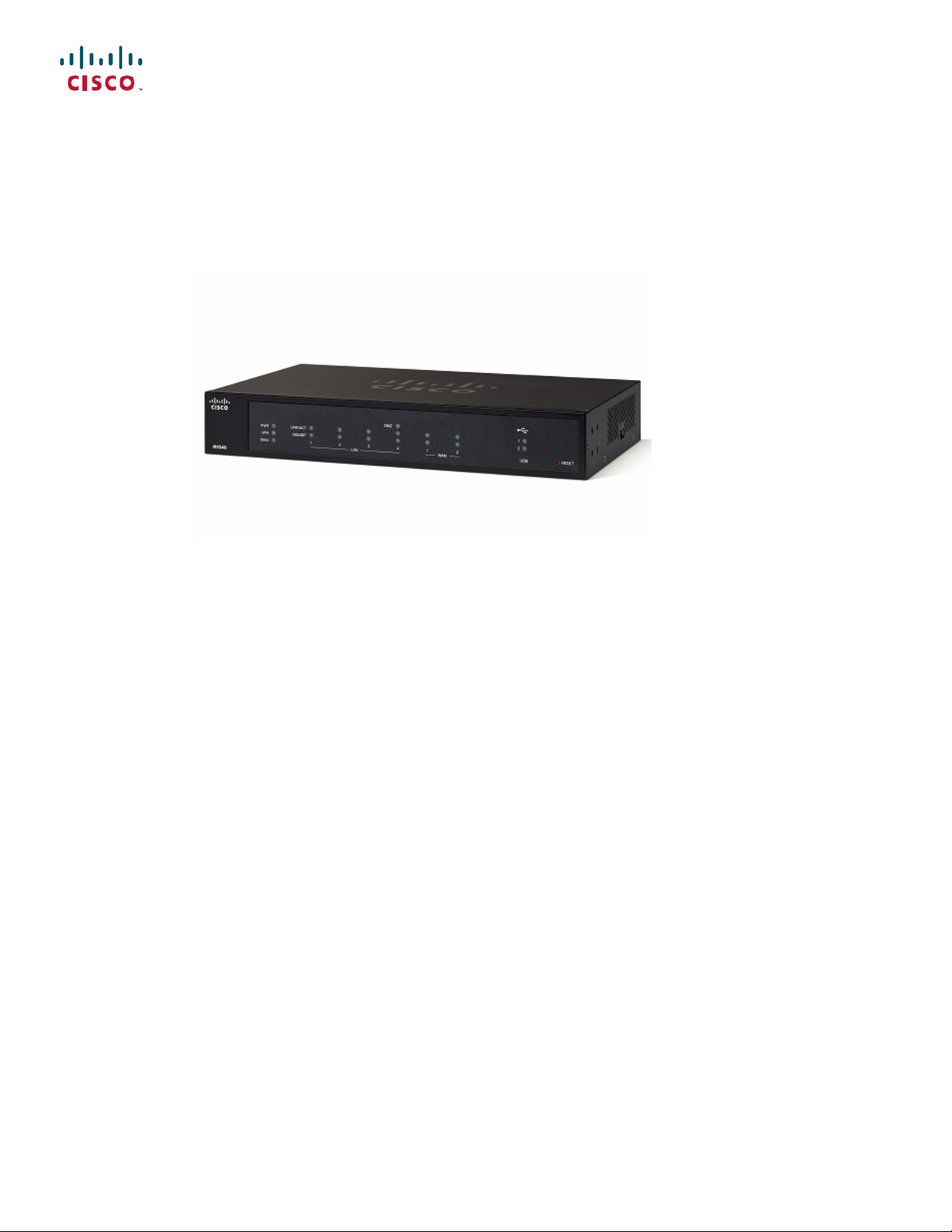
During the system boot up, the power LED will progressively keep flashing until the system has fully booted.
At start up, the PWR, LINK/ACT and GIGIBIT LEDs of LAN 1 will flash. At 25% boot up, the PWR, LINK/ACT
and GIGIBIT LEDs of LAN 1 and 2 will flash. At 50% boot up, the PWR, LINK/ACT and GIGIBIT LEDs of
LAN 1, 2 and 3 will flash. At 75% boot up, the PWR, LINK/ACT and GIGIBIT LEDs of LAN 1, 2, 3 and 4
will flash.
The system boot time will be less than 3 minutes typically. If the router is fully configured with all feature
configuration settings set to a maximum, it may take up to 7 minutes to fully boot the system.
Table 1: Description of Router's LEDs
PWR
DIAG
LINK/ACT of WAN1, WAN2 and
LAN 1-4
Off when the device is powered off.
Solid green when the device is powered on and booted.
Flashing green when the device is booting up.
Off when the system is on track to bootup.
Slow blinking red (1Hz) when the firmware upgrade is in progress.
Fast blinking red (3Hz) when the firmware upgrade is failing.
Solid red when the system failed to boot-up with both active and inactive images
or in rescue mode.
Off when there is no Ethernet connection.
Solid green when the GE Ethernet link is on.
Flashing green when the GE is sending or receiving data.
GIGABIT of WAN1, WAN2 and LAN
1-4
DMZ
VPN
USB1 and USB2
Solid green when at 1000M speed.
Off when at non-1000M speed.
Solid green when the DMZ is enabled.
Off when the DMZ is disabled.
Off when no VPN tunnel is defined, or all defined VPN tunnels have been
disabled.
Solid green when at least one VPN tunnel is up.
Flashing green when sending or receiving data over VPN tunnel.
Solid amber when no enabled VPN tunnel is up.
Off when no USB device is connected, or is inserted but not recognized.
Solid green when the USB dongle is connected to the ISP successfully. USB
storage is recognized.
Flashing green when sending or receiving data.
Solid amber when the USB dongle is recognized but fails to connect to ISP
(no IP address is assigned). The USB storage access has errors.
RV340 Administration Guide
2
Page 9

Introduction
Launch Setup Wizard
RESET
Launch Setup Wizard
From the Launch Setup Wizard page, you can follow the instructions that guide you through the process for
configuring the device.
To open this page, select Launch Setup Wizard in the navigation tree and follow the on-screen instructions
to proceed. Refer to your ISP for the information required to setup your Internet connection.
Launch Setup Wizard
Wizard
To reboot the router, press the reset button with a paper clip or pen tip for less
than 10 seconds.
To reset the router to factory default settings, press and hold the reset button
for 10 seconds.
Directs you to the Initial Setup Wizard.Initial Setup Wizard
Directs you to the VPN Status Wizard.VPN Setup Wizards
Directs you to the Application Control Wizard.Application Control
Initial Configurations
Change Administrator
Password
Configure WAN Settings
Configure USB Settings
Configure LAN Settings
Quick Access
Upgrade Router
Firmware
Configure Remote
Management Access
Directs you to the User Accounts page where you can change the administrator
password and set up a guest account.
Directs you to the WAN Settings page where you can modify the WAN
parameters.
Directs you to the Mobile Network page where you can modify the USB
configurations.
Directs you to the VLAN Membership page where you can configure the
VLAN.
Directs you to the File Management page where you can update the device
firmware.
Directs you to the FireWall >Basic Settings page where you can enable the
basic features of the device.
RV340 Administration Guide
3
Page 10

Troubleshooting Tips
Introduction
Backup Device
Configuration
Device Status
System Summary
VPN Status
Port Statistics
Traffic Statistics
Troubleshooting Tips
If you have trouble connecting to the Internet or the web-based web interface:
Directs you to the Config Management page where you can manage the router’s
configuration.
Directs you to the System Summary page that displays the IPv4 and IPv6
configuration, and firewall status on the device.
Directs you to the VPN Status page that displays the status of the VPNs managed
by this device.
Directs you to the Port Traffic page which displays the device’s port status and
port traffic.
Directs you to the TCP/IP Services page which displays the device’s port listen
status and the established connection status.
Directs you to the View Logs page which displays the logs on the device.View System Log
•
•
•
•
•
User Interface
The user interface is designed to make it easy for you to set up and manage your device.
Navigation
The major modules of the web interface are represented by buttons in the left navigation pane. Click a button
to view more options. Click an option to open a page.
Popup windows
Some links and buttons launch popup windows that display more information or related configuration pages.
If your web browser displays a warning message about the popup window, allow the blocked content.
Verify that your web browser is not set to work offline.
Check the local area network connection settings for your Ethernet adapter. The PC should obtain an IP
address through DHCP. Alternatively, the PC can have a static IP address in the 192.168.1.x range with
the default gateway set to 192.168.1.1 (the default IP address of the device).
Verify that you entered the correct settings in the Wizard to set up your Internet connection.
Reset the modem and the device by powering off both devices. Next, power on the modem and let it sit
for about 2 minutes. Then, power on the device. You should now receive a WAN IP address.
If you have a DSL modem, ask your ISP to put the DSL modem into bridge mode.
RV340 Administration Guide
4
Page 11

Introduction
User Interface
Help
To view information about the selected configuration page, click Help at the top right corner of the web
interface. If your web browser displays a warning message about the popup window, allow the blocked content.
Logout
To exit the web interface, click Logout near the top right corner of the web interface. The sign-in page appears.
RV340 Administration Guide
5
Page 12

User Interface
Introduction
RV340 Administration Guide
6
Page 13

CHAPTER 2
Status and Statistics
This section provides information on the various configuration settings of your device and contains the
following topics:
System Summary, page 7
•
TCP/IP Services, page 9
•
Port Traffic, page 9
•
WAN QoS Statistics, page 10
•
Application Statistics, page 11
•
Connected Devices, page 12
•
Routing Status, page 12
•
DHCP Bindings, page 12
•
Mobile Network, page 13
•
VPN Status, page 13
•
View Logs, page 15
•
System Summary
The System Summary provides a snapshot of the settings on your device. It displays your device’s firmware,
serial number, port traffic, routing status, mobile networks, and VPN server settings. To view this System
Summary, click Status and Statistics> System Summary.
System Information
• Host Name — Name of host.
• Serial Number — Serial number of the device.
• System Up Time — Length of time in yy-mm-dd, hours, and minutes that the device has been active.
• Current Time — Current time and date.
RV340 Administration Guide
7
Page 14

System Summary
Status and Statistics
• PID VID — Version number of the hardware.
Firmware Information
• Firmware Version — Version number of the installed firmware.
• Firmware MD5 Checksum — A value used for file validation.
Port Status
• Port ID — Defined name and number of the port.
• Interface — Name of the port used for the connection.
• Enabled — Status of the port.
• Speed — The speed (in Mbps) of the device after auto negotiation.
IPv4 and IPv6
• Interface — Name of the interface.
• IP Address — IP address assigned to the interface.
• Default Gateway — Default gateway for the interface.
• DNS — IP address of the DNS server.
• Dynamic DNS — IP address of the DDNS for the interface: Disabled or Enabled.
• Renew — Click to renew the IP address.
• Release — Click to release the interface.
VPN Status
• Type — Type of the VPN tunnel.
• Active — Is Enabled or Disabled.
• Configured — VPN tunnel’s status whether it is configured or not.
• Max Supported Sessions — The maximum number of tunnels supported on the device.
• Connected Session — Status of the tunnel.
Firewall Setting Status
• Stateful Packet Inspection (SPI) — also known as dynamic packet filtering, monitors the state of active
connections and uses this information to determine which network packets are allowed through the
firewall.
• Denial of Service (Dos) — Status of the Dos filter service is enabled (On) or disabled (Off). A DoS
attack is an attempt to make a machine or network resource unavailable to its intended users.
RV340 Administration Guide
8
Page 15

Status and Statistics
• Block WAN Request — Makes it difficult for outside users to work their way into your network by
hiding the network ports from Internet devices and preventing the network from being detected by other
Internet users.
• Remote Management — Indicates that a remote connection for managing the device is allowed or
denied.
• Access Rule — Number of access rules that have been set.
Log Setting Status
• Syslog Server — Status of system logs.
• Email Log — Status of logs to send using email.
TCP/IP Services
The TCP/IP Services page displays the statistics of the protocol, port, and IP address. To view the TCP/IP
Services, click Status and Statistics > TCP/IP Services.
TCP/IP Services
Port Traffic
Port Listen Status
• Protocol — Type of protocol used for communication.
• Listen IP Address — The listening IP address on the device.
• Listen Port — The listening port on the device.
Established Connection Status
• Protocol — Type of protocol used for communication.
• Local IP Address — IP address of the system.
• Local Port — Listening ports on different services.
• Foreign Address — IP address of the device connected.
• Foreign Port — Port of the device connected.
• Status — Connection status of the session.
The Port Traffic page displays the statistics and status of the interfaces of the device. To view the device’s
Port Traffic page, click Status and Statistics >Port Traffic.
Port Traffic
• Port ID — Defined name and number of the port.
• Link Status — Status of the interface.
RV340 Administration Guide
9
Page 16

WAN QoS Statistics
Status and Statistics
• Rx Packets — Number of packets received on the port.
• Rx Bytes — Number of packets received, measured in bytes.
• Tx Packets — Number of packets sent on the port.
• Tx Bytes — Number of packets sent and measured in bytes.
• Packet Error — Details about the error packets.
• Refresh — To refresh the displayed statistics.
• Reset Counters — To reset all values to zero.
Port Status
• Port ID — Defined name and number of the port.
• Link Status — Status of the interface.
• Port Activity — Status of the port (example: port enabled or disabled or connected).
• Speed Status — The speed (in Mbps) of the device after auto negotiation.
• Duplex Status — Duplex mode: Half or Full.
• Auto Negotiation — Status of the auto negotiation parameter. When enabled (On), it detects the duplex
mode, and if the connection requires a crossover, automatically chooses the MDI or MDIX configuration
that matches the other end of the link.
WAN QoS Statistics
The WAN QoS Statics page displays the statistics of the outbound and inbound WAN QoS. To view the
device’s WAN QoS Statics page, click Status and Statistics > WAN QoS Statistics.
• Interface — Name of the interface.
• Policy Name — Name of the policy.
• Description — Description of the WAN QoS statistics.
• Clear Counters — Click to clear the counters.
Outbound QoS Statistics
• Queue — Number of outbound queues.
• Traffic Class — Name of traffic class assigned to queue.
• Packets Sent — Number of outbound packets of the traffic class sent.
• Packets Dropped — Number of outbound packets dropped.
Inbound QoS Statistics
• Queue — Number of inbound queues.
RV340 Administration Guide
10
Page 17

Status and Statistics
• Traffic Class — Name of traffic class assigned to queue.
• Packets Sent — Number of traffic class inbound packets sent.
• Packets Dropped — Number of inbound packets dropped.
Application Statistics
The Application Statistics displays the usage data of the router. To view the Application Statistics page, click
Status and Statistics > Applications Statistics.
• Clear Counters — To reset all the table statistics.
Top Applications by Category
• Category — List of application categories accessed.
• Traffic Volume — Traffic volume in megabytes.
Application Statistics
Top Applications by Name
• Applications — List of applications accessed.
• Traffic Volume — Traffic volume in megabytes.
Top Talkers
• Talkers — List of IP addresses accessed.
• Traffic Volume — Traffic volume in megabytes.
Top Talkers by Device Type
• Device — List of devices accessed.
• Traffic Volume — Traffic volume in megabytes.
Top Talkers by OS Type
• OS — List of operating systems used.
• Traffic Volume — Traffic volume in megabytes.
Note
A pop-up stating AVC disabled or license expired may appear if the AVC is disabled or the license is
expired.
RV340 Administration Guide
11
Page 18

Connected Devices
Connected Devices
The Connected Devices page lists all the connected devices on the router. To view this Connected Devices
page, click Status and Statistics > Connected Devices.
IPv4
• Hostname — Name of the connected device.
• IPv4 Address — Connected device’s IP Address.
• MAC Address — MAC address of the connected device.
• Type — Type of device IP address.
• Interface — The interface it is connected to.
IPv6
Status and Statistics
• IPv6 Address — The IPv6 address of the connected device.
• MAC Address — MAC address of the connected device.
Routing Status
Routing is the process of moving packets across a network from one host to a another. The Routing Status of
this process is displayed on a routing table. The routing table contains information about the topology of the
network immediately around it. To view the device’s Routing Status for IPv4 and IPv6, click Status and
Statistics > Routing Status.
IPv4 and IPv6 Routes
• Destination — IP Address and subnet mask of the connection.
• Next Hop — IP address of the next hop. Maximum number of hops (the maximum is 15 hops) that a
• Metric — Number of routing algorithms when determining the optimal route for sending network traffic.
• Interface — Name of the interface to which the route is attached to.
• Source — Source of the route.
packet passes through.
DHCP Bindings
The DHCP Bindings page displays the statistics of the DHCP client information such as IP address, MAC
address, Lease Expire Time and Type of Binding (static or dynamic). To view the device’s DHCP Bindings,
click Status and Statistics > DHCP Bindings.
In the DHCP Binding Table, the following is displayed:
RV340 Administration Guide
12
Page 19

Status and Statistics
• IPv4 Address — Assigned IP address.
• MAC Address — The MAC address of the clients’ assigned IP address.
• Lease Expires — Lease time for the client’s system.
• Type — Status of the connection (Static or Dynamic).
Mobile Network
Mobile networks enables a router and its subnets to be mobile while continuing to maintain IP connectivity
transparent to the IP hosts connecting to the network through this mobile router. To view the router’s mobile
network, click Status and Statistics > Mobile Network. Next, select the Interfaces from the drop-down list
(USB1 or USB2). Click Refresh to refresh mobile network status.
Connection
• Internet IP Address — IP address served by the service provider.
Mobile Network
• Subnet Mask — Mask served by the service provider.
• Default Gateway — Default gateway served by the service provider.
• Connection Up Time — Time duration of connected device.
• Current Dial-Up Session Usage — Data usage per session.
• Monthly Usage — Monthly data usage.
Data Card Status
• Manufacturer — Manufacturer of the device.
• Card Firmware — Firmware version provided by the manufacturer.
• SIM Status — Status of the SIM.
• IMSI — Unique number of the device.
• Carrier — Name or type of data carrier.
• Service Type — Data service type.
• Signal Strength — Strength of data signal.
• Card Status — Card status disconnected or connected.
VPN Status
The VPN Status displays the tunnel status of the Site-to-Site, Client-to-Site, SSL VPN, PPTP, L2TP, and
Teleworker VPN Client. To view the device’s VPN status, click Status and Statistics > VPN Status.
RV340 Administration Guide
13
Page 20

VPN Status
Status and Statistics
Site-to-Site Tunnel Status
• Tunnel(s) Used — VPN tunnels in use.
• Tunnel(s) Available — Available VPN tunnels.
• Tunnel(s) Enabled — VPN tunnels enabled.
• Tunnel(s) Defined — Defined VPN tunnels.
In the Connection Table, you can add, edit, delete, or refresh a tunnel. (See Site-to-Site, on page 80). You
can also click on Column Display Selection to select the column headers displayed in the Connection Table.
Client-to-Site Tunnel Status
In this mode, the client from Internet connects to the server to access the corporate network/LAN behind the
server. For a secure connection, you can implement a client-to-site VPN. You can view all the Client-to-Tunnel
connections, add, edit, or delete the connections in the Connection Table. (See Client to Site, on page 85).
The Connection Table displays the following:
• Group or Tunnel Name — Name of the VPN tunnel. This is for reference purposes only and does not
match the name used at the other end of the tunnel.
• Connections — Status of the connection.
• Phase2 Encryption/Auth/Group — Phase 2 encryption type
(NULL/DES/3DES/AES-128/AES-192/AES-256), authentication method (NULL/MD5/SHA1), and
DH group number (1/2/5).
• Local Group — IP address and subnet mask of the local group.
SSL VPN Status
A Secure Sockets Layer virtual private network (SSLVPN) allows users to establish a secure, remote-access
VPN tunnel to this device by using a web browser. SSL VPN provides secure, easy access to a broad range
of web resources and web-enabled applications from almost any computer on the Internet. Here, you can view
the status of the SSL VPN tunnels.
• Tunnel(s) Used — SSL VPN Tunnels used for connection.
• Tunnel(s) available — Available tunnels for the SSL VPN connection.
The Connection Table shows the status of the established tunnels. You can also add edit or delete connections.
• Policy Name — Name of the policy applied on the tunnel.
• Session — Number of sessions.
You can also add, edit or delete a SSL VPN. (See SSL VPN, on page 92).
PPTP Tunnel Status
Point-to-Point Tunneling Protocol has the capability to encrypt data with 128-bit. It is used to ensure that
messages sent from one VPN node to another are secure.
• Tunnel(s) Used — PPTP Tunnels used for the VPN connection.
RV340 Administration Guide
14
Page 21

Status and Statistics
View Logs
• Tunnel(s) Available — Available tunnels for the PPTP connection.
The Connection Table — shows the status of the established tunnels. You can also connect or disconnect
these connections.
• Session ID — Session ID of the proposed or current connection.
• Username — Name of the connected user.
• Remote Access — IP address of the remotely connected or proposed connection.
• Tunnel IP — IP address of the tunnel.
• Connect Time — Time of the tunneling time.
• Action — Connect or disconnect the tunnel.
L2TP Tunnel Status
Layer 2 Tunneling Protocol is the method used to enable Point-to-Point sessions by using the Internet at Layer
2. You can find the status of L2TP Tunnel Status.
View Logs
• Tunnel(s) Used — L2TP tunnels used for the VPN connection.
• Tunnel(s) available — Available tunnels for the L2TP connection.
The Connection Table — Shows the status of the established tunnels. You can also connect or disconnect
these connections.
• Session ID — Session ID of the proposed or current connection.
• Username — Name of the connected user.
• Remote Access — IP address of the remotely connected or proposed connection.
• Tunnel IP — IP address of the tunnel.
• Connect Time — Time of the tunneling time.
• Action — Connect or disconnect the tunnel.
The View Logs page displays all of the device’s logs. You can filter these logs based on category, severity,
or keyword. You can also refresh, clear, and export these logs to a PC or USB. To view the device’s logs,
follow these steps:
Step 1
Step 2
Click Status and Statistics > View Logs.
Under Logs Filtered By, select the appropriate option.
RV340 Administration Guide
15
Page 22

View Logs
Status and Statistics
Step 3
Step 4
Category
Click any of the following to view logs:
• All — Displays all the logs.
• Category — Displays the selected category logs.
Select one of the options displayed to view the logs based on the severity.Severity
Enter a keyword to display the logs based on the keyword.Keyword
Click Show Logs.
Note
To configure log settings, see Log, on page
28.
Click any of the following options:
• Refresh — Click to refresh logs.
• Clear Logs — Click to clear logs.
• Export Logs to PC — Click to export logs to PC.
• Export Logs to USB — Click to export logs on to a USB storage device.
RV340 Administration Guide
16
Page 23

Reboot
CHAPTER 3
Administration
This section describes the device's administration features and contains the following topics:
Reboot, page 17
•
File Management, page 18
•
Diagnostic, page 20
•
License, page 21
•
Certificate, page 22
•
Config Management, page 23
•
The Reboot allows users to restart the device with active or inactive images.
To access Reboot page, follow these steps:
Step 1
Step 2
Step 3
Step 4
Click Administration >Reboot.
In the Active Image after Reboot section, select an option (Active Image x.x.xx.xx or Inactive Image x.x.xx.xx) from
the drop-down list.
Select the preferred reboot option.
Reboot the device.
•
Return to factory default settings after reboot.
•
Return to factory default settings including certificates after reboot.
•
Click Reboot to reboot device.
RV340 Administration Guide
17
Page 24

File Management
File Management
The File Management provides a snapshot of your device. To view the File Management info, follow these
steps:
Administration
Step 1
Click Administration> File Management. to see the following information:
System Information
• Device Model — Model number of the device.
• PID VID— PID and VID number of the router.
• Current Firmware Version — Current firmware version.
• Latest Updated — Date of last firmware update.
• Latest Version Available on Cisco.com — Latest firmware version.
• Last Checked — Date when last checked.
Signature
• Current Signature Version — Version of the signature.
• Last Update — Last date of when an update was performed.
• Latest Version Available on Cisco.com — Latest signature version.
• Last Checked — Date when last checked.
USB Dongle Driver
• Current Dongle Driver Version — Version of built-in USB dongle driver.
• Last Update — Last date of when an update was performed.
• Latest Version Available on Cisco.com — Latest dongle driver version.
• Last Checked — Date when last checked.
Language Package
• Current Language Package Version — Version of the language package.
• Last Update — Date when last updated.
• Latest Version Available on Cisco.com — Latest language package version.
• Last Checked — Date when last checked.
Manual Upgrade
In the Manual Upgrade section, you can upload and upgrade to a newer version of the firmware, signature file, USB
dongle driver or language file.
RV340 Administration Guide
18
Page 25

Administration
Manual Upgrade
During a firmware upgrade, do not try to go online, turn off the device, shut down the PC, or interrupt the
process in any way until the operation is complete. This process takes about a minute, including the reboot
process. Interrupting the upgrade process at specific points when the flash memory is being written to may
corrupt it and render the router unusable.
Step 2
Caution
If you select to upgrade from the USB drive, the router will search the USB flash drive for a firmware image file whose
name has one or more of the following: PID, MAC address, and Serial Number. If there are multiple firmware files in
the USB flash drive, the router will check the one with the most specific name, i.e. priority from high to low.
Manual Upgrade
To update the router with a newer version of the firmware.
Step 1
Step 2
Step 3
Step 4
Step 5
Select Administration > File Management.
In the Manual Upgrade section, select the file type (Firmware Image, Signature File, USB Dongle Driver or Language
File).
In the Upgrade From section, select an option (Cisco.com, PC, or USB) and click Refresh.
Check Reset all configuration/setting to factory defaults to reset all the configuration and apply factory defaults.
Click Upgrade to upload the selected image to the device.
Auto Update
The router supports loading a firmware from USB flash drive if the USB stick is present during the system
bootup. The router will search the USB flash drive for a firmware image file whose name has one or more of
the following: PID, MAC address, and Serial Number. If there are multiple firmware files in the USB flash
drive, the router will check the one with the most specific name, i.e. priority from high to low.
PID-MAC-SN.IMG
•
PID-SN.IMG
•
PID-MAC.IMG
•
PID.IMG
•
The files with other names will be ignored. If the version is higher than the current version, it will be upgraded
to this image and the DUT will reboot. After that, the upgrade process will start again.
If it does not find a more recent image in the USB1, then it will check the USB2 using the same logic.
The router also supports loading a configuration file from a USB flash drive during the system bootup.
The behavior only happens when the router is in factory default and attached with a USB flash drive
•
before it is
powered on.
RV340 Administration Guide
19
Page 26

Diagnostic
Administration
The router will search the USB flash drive for a config file whose name has one or more of the following:
•
PID,
MAC address, and Serial Number. If there are multiple firmware files in the USB flash drive, the router
will check
the one with the most specific name, i.e. priority from high to low.
PID-MAC-SN.xml
◦
PID-SN.xml
◦
PID-MAC.xml
◦
PID.xml
◦
The files with the other names will be ignored.
Firmware Auto Fallback Mechanism
The device includes two firmware images in the flash to provide an Auto Fallback Mechanism so that the
device can automatically switch to the secondary firmware when the active firmware is corrupted or cannot
boot up successfully after five trials.
The Auto Fallback Mechanism operates as follows:
Diagnostic
1
The device first boots up with the active firmware.
2
If the firmware is corrupted, it will switch to the secondary firmware automatically after the active firmware
has failed to boot up after 5 times. If the router gets stuck does not reboot automatically, you can turn off
the power, power on, wait for 30 seconds, then turn off the power, for 5 times to switch to the secondary
or inactive firmware.
3
After booting up with the secondary or inactive firmware, please check to see if anything is wrong with
the active firmware.
4
Reload the new firmware again if necessary.
Your device provides several diagnostic tools to help you with troubleshooting network issues. Use the
following diagnostic tools to monitor the overall health of your network.
Using Ping or Trace
RV340 Administration Guide
20
Page 27

Administration
License
You can use the Ping or Trace utility to test connectivity between this router and another device on the network.
To use Ping or Trace, follow these steps:
Step 1
Step 2
Step 3
Step 4
Select Administration > Diagnostic.
In the Ping or Trace an IP Address section, in the IP Address/Domain Name field, enter an IP address or domain name.
Click Ping. The ping results appear. This tells you if the device is accessible. Or click Traceroute. The traceroute results
appear.
To perform a DNS lookup, enter the IP address or domain name in the Perform a DNS Lookup>IPAddress/Domain
Name field and click Lookup.
License
In the License section, you can configure the licenses or register the router. It simplifies the Cisco software
experience and helps you understand how the Cisco software is used.
Smart Software Licensing Status
The Smart Software Licensing Status section displays your device’s license information.
Registration Status — Registered or Unregistered, and date of registration.
License Authorization Status — Authorized or Evaluation Mode or Out of Compliance or Authorization
Expired or Evaluation Period Expired and the date of license authorization.
Export-Controlled Functionality — Not allowed by default.
Smart License Usage
You can select the Smart License to be used for the router. Make sure that you have enough of licenses in the
virtual account for the router, otherwise it is not compliant.
To configure the Smart License, follow these steps:
Step 1
Step 2
Step 3
Step 4
Under Smart License Usage, click Choose Licenses.
Check the applicable licenses and enter a number under Count.
Click Save.
A License Authorization Renewal pop-up will appear, click OK.
RV340 Administration Guide
21
Page 28

Certificate
Certificate
Certificates are important in the communication process. The certificate signed by a trusted Certificate Authority
(CA), ensures that the certificate holder is really who he claims to be. Without a trusted signed certificate,
data may be encrypted, however, the party you are communicating with may not be the one whom you think.
A list of certificates with the certificate details are displayed on this page. You can export a Self signed, local,
and CSR certificate. Or, you can import a CA, Local, or PKCS#12 certificate. You can also import a certificate
file (from PC/USB) to a new certificate.
If a device certificate is imported, it replaces its corresponding CSR certificate.
On Certificate Table, the certificates that are associated to the router are displayed. You can you delete, export,
view the details, or import a certificate that is listed in the Certificate Table.
Import Certificate
To import a certificate, follow these steps:
Administration
Step 1
Step 2
Step 3
Step 4
Step 5
Step 6
Click Import Certificate.
Select the type of certificate to import from the drop-down list:
Local Certificate
•
CA Certificate
•
PKCS#12 encoded file.
•
Enter a certificate name. (For PKCS#12, you must enter a password).
Check Import from PC and click Choose File to upload and import the certificate from a specific location.
Check Import From USB and click Refresh to upload and import the certificate from a USB key.
Click Upload.
Generate CSR/Certificate
Step 1
Step 2
Step 3
Click Generate CSR/Certificate.
Select the type of certificate to generate from the drop-down list.
Enter the following information:
Certificate Name
Enter a name for certificate. Certificate name should not contain spaces or special
characters.
Enter a name and select one of the following: IP Address, FQDN, or Email.Subject Alternative Name
RV340 Administration Guide
22
Page 29

Administration
Config Management
Select a country from the drop-down list.Country Name
Enter a State or Province.State or Province Name
Enter a locality name.Locality Name
Enter the name of the organization.Organization Name
Enter the name of the organization unit.Organization Unit Name
Enter a common name.Common Name
Enter the email address.Email Address
Select the Key Encryption Length from the drop-down menu. It should be 512, or 2048.Key Encryption Length
Enter the number of days (Range 1-10950, Default: 360).Valid Duration
Step 4
Click Generate.
Config Management
Config Management page provides details on the router’s file configurations.
Configuration File Name
The Configuration File Name displays the last changed time details on the following:
Running Configuration
•
Startup Configuration
•
Mirror Configuration
•
Backup Configuration
•
Copy/Apply Configuration
The Copy/Apply Configuration section displays the default configuration of the device uses the running
configuration file, which is unstable and does not retain the settings between reboots. You can save this running
configuration file to the startup configuration file.
• Source File Name — Select the source file name from the drop-down list.
• Destination File Name — Select the destination file name from the drop-down list.
• Save Icon Blinking — Indicates whether an icon blinks when there is unsaved data. To disable/enable
this feature, click Disable Save Icon Blinking.
RV340 Administration Guide
23
Page 30

Config Management
Administration
RV340 Administration Guide
24
Page 31

CHAPTER 4
System Configuration
The System Configuration Wizard provides guidance when installing and configuring the router. This section
contains the following topics:
Initial Setup Wizard, page 26
•
System, page 27
•
Time, page 27
•
Log, page 28
•
Email, page 30
•
User Accounts, page 31
•
User Groups, page 33
•
IP Address Group, page 34
•
SNMP, page 35
•
Discovery Bonjour, page 35
•
LLDP, page 36
•
Automatic Updates, page 37
•
Service Management, page 38
•
Schedule, page 38
•
RV340 Administration Guide
25
Page 32

Initial Setup Wizard
Initial Setup Wizard
You can check the connection and configure the basic router settings on the Initial Setup Wizard page. From
the Run Setup Wizard page, you can follow the instructions that guide you through the process for configuring
the device.
System Configuration
Step 1
Step 2
Step 3
Step 4
Step 5
Step 6
Step 7
Step 8
Click System Configuration > Initial Setup Wizard.
Click Next to go to Check Connection page. If your router has detected a connection, the connection details are displayed
on this page.
Select Interface from the drop-down list.
Click Next.
Under Configure Router Select Connection Type, select your internet connection type.
If you select Dynamic IP or DHCP, click Next.
If you select Static IP Address, click Next and configure the settings below.
Enter the static IP address.Static IP Address
Enter the subnet mask.Subnet Mask
Enter the gateway IP.Gateway IP
Enter the IP address of the DNS.DNS
If you select PPPoE, click Next and configure the settings below.
Enter the account name.Account Name
Enter the password.Password
Confirm the password.Confirm Password
Step 9
26
If you select PPTP or L2TP, click Next and configure the settings below.
Enter the account name.Account Name
Enter the password.Password
Confirm the password.Confirm Password
Enter the static IP address.Static IP Address
Enter the subnet mask.Subnet Mask
Enter the gateway IP.Gateway IP
Enter the remote server.Remote Server
Enter the IP address of the DNS.DNS
RV340 Administration Guide
Page 33

System Configuration
System
Step 10
Step 11
Step 12
Step 13
Step 14
Step 15
Select the router’s time zone from the Time Zone drop down list.
Select one of the following:
Click Next.
In the Choose a MAC address section, select one of the options below:
Click Next.
In the Summary section, review your settings and click Submit.
System
Enable Network Time Protocol Synchronization to set the date and time automatically.
•
Set the date and time manually to set the date and time manually. Enter the date and time.
•
Use Default Address (Recommended).
•
• Use this computer’s address.
• Use this address — Enter a MAC address.
Your ISP may assign a hostname and a domain name to identify your device or require you to specify the
same. In the former case, the default values can be changed as needed. Follow these steps to assign a host and
domain name.
Step 1
Step 2
Step 3
Step 4
Time
Click System Configuration > System.
In the Host Name field, enter a host name.
In the Domain Name field, enter a domain name.
Click Apply.
Setting the time is critical for a network device so that every system log and error message is timestamped
for accurate tracking and synchronizing the data transfer with other network devices.
You can configure the time zone, adjust for daylight savings time if necessary, and select the Network Time
Protocol (NTP) server to synchronize the date and time.
RV340 Administration Guide
27
Page 34

Log
System Configuration
To configure the time and NTP server settings, follow these steps;
Step 1
Step 2
Step 3
Step 4
Step 5
Log
Click System Configuration > Time.
Set Time Zone — Select your time zone relative to Greenwich Mean Time (GMT).
Set Date and Time — Select Auto or Manual.
a)
Auto — Check Default or User Defined and enter a qualified NTP Server name.
b)
Manual — Enter the date and time.
Set Daylight Savings Time—Check to enable daylight savings time. You can choose the Daylight Saving Mode — By
Date or Recurring and enter the start dates and end dates. You can also specify the Daylight Saving Offset in minutes.
Click Apply.
One of the basic settings of a network device is its system log (Syslog), which is used to log the device data.
You can define the instances that should generate a log. Whenever such defined instance occurs, a log is
generated with the time and event and sent to a syslog server or sent in an email. Syslog can then be used to
analyze and troubleshoot a network and to increase the network security.
Configure Log Settings
To configure the log settings, follow these steps:
Step 1
Step 2
Step 3
Step 4
Click System Configuration > Log.
Under Log Setting, in the Log section, check Enable.
In the Log Buffer field, enter the number of KB (Range 1 KB to 4096 KB, Default is 1024 KB).
Severity- select the appropriate log severity level from the drop down list. They are listed from the highest to the lowest.
Level 0, which means that the system is unusable.Emergency
Level 1, which indicates that immediate action is needed.Alert
Level 2, which indicates that the system is in critical condition.Critical
Error
Warning
Notification
Information
Level 3, which indicates that there is an error in the device, such as a single port being
off-line.
Level 4, which indicates that a warning message is logged when the device is functioning
properly, but an operational problem has occurred.
Level 5, which indicates a normal but significant condition. A notification log is logged
when the device is functioning properly, but a system notice has occurred.
Level 6, which indicates a condition that is not a condition error, but requires special
handling.
RV340 Administration Guide
28
Page 35

System Configuration
Email Server
Step 5
Debugging
Level 7, which indicates that the debugging messages contain information normally of
use only when debugging a program.
Category - check All or any of the required event categories that you want logged on the device.
Logs involving kernel code.Kernel
Logs involving license violations.License
Logs related to user-space applications such as NTP, Session, and DHCP.System
Logs related to events that triggered web filtering.Web Filter
Logs related to firewall rules, attacks, and content filtering.Firewall
Logs related to application control.Application Control
Logs related to routing, DHCP, WAN, LAN, and QoS.Network
Logs related to users activities.Users
VPN
VPN-related logs including instances like VPN tunnel establishment failure, VPN
gateway failure, and so on.
Logs from the 3G/4G dongles which are plugged into the router.3G/4G
Logs related to SSLVPN.SSLVPN
Step 6
In Save to USB Automatically, check Enable to save the logs automatically.
Email Server
The email server can be configured to your email account. The email server logs are periodically sent to
specific email address, so that the administrator is always up to date on the network. The router supports
RV340 Administration Guide
29
Page 36

Remote Syslog Server
System Configuration
SMTP mail account configuration such as email addresses, password, message digest; optional parameters,
SMTP server port number, SSL, TLS.
Step 1
Step 2
Step 3
Step 4
Step 5
Step 6
Step 7
In the Email Server section, check Email Syslogs to enable the router to send email alerts when events are logged.
In the Email Settings section, click Link to Email Setting page to configure your email settings.
In the Email Subject section, enter the subject.
In the Severity section, select the severity level from the drop-down list.
In the Log Queue Length section, enter a range from 1 to 1000. The default is 50.
In the Log Time Threshold section, select the time threshold from the drop-down list.
In the Real Time Email Alerts section, check All or any of the e-mail alerts categories that you want logged on the
device.
Remote Syslog Server
A remote syslog server allows you to separate the software that generates the messages and events from the
system that stores and analyzes them. When enabled, the network driver sends messages to a syslog server
on the local Intranet or Internet through a VPN tunnel. The syslog server can be configured by specifying the
name or IP address.
Step 1
Step 2
Step 3
Step 4
In the Syslog Server section, check Enable to enable sending system logs to a remote server.
In the Syslog Server1 field, enter the IP address of a syslog server to which the log messages should be sent.
In the Syslog Server2 field, enter the IP address of a syslog server to which the log messages should be sent.
Click Apply.
Step 1
Step 2
30
You can configure your device’s email server to your specifications.
Configuring Email
To configure the email server, follow these steps.
Select System Configuration > Email.
Under Email Server, enter the following:
Enter the address of the SMTP server.SMTP Server
Enter the SMTP port.SMTP Port
RV340 Administration Guide
Page 37

System Configuration
User Accounts
Select None or TLS/SSL as the email encryption method.Email Encryption
Authentication
Step 3
Step 4
Click Test Connectivity to Email Server to test connectivity.
Click Apply.
User Accounts
You can create, edit, and delete local users and authenticate them using local database for various services
like PPTP, VPN Client, Web GUI login, and SSLVPN. This enables the administrators to control and allow
only the local users access the network.
To create local users and determine the password complexity, follow these steps:
Select the type of authentication from the drop-down list: None, Login, Plaintext or
MD5.
Enter an email address to send to.Send Email to 1
Enter an email address to send to (optional).Send Email to 2
Enter an email address to send from.From Email Address
Step 1
Step 2
Step 3
Step 4
Step 5
Select System Configuration > User Accounts.
Under Local Users Password Complexity, check Enable to enable the password complexity.
Configure the password complexity settings.
Minimal password length
Minimal number of
character classes
The new password must be
different than the current
one
In the Local Users Membership List table, click Add to add a user on the router.
In the Add User Account page, enter the following information:
Enter the minimum length of the password to create a new password (Range 0 to 64,
Default 8).
Enter the minimum number of character classes that should be used for the new password
(Range 0 to 4, Default 3). Compose a password using three of these four classes:
(Uppercase, letters, lower case letters, numbers or special characters).
Enable to require the user to enter a different password when the current password
expires.
Enter a username.Username
Enter a password.New Password
Confirm the password.New Password Confirm
RV340 Administration Guide
31
Page 38

Remote Authentication Service
System Configuration
Displays password strength.Password Strength Meter
Select a group (admin or guest) from the drop-down list.Group
Step 6
Step 7
Step 8
Click Apply.
Click Edit or Delete to edit or delete an existing user.
In the Edit User Account page, enter the following information:
Enter the old password.Old Password
Enter the new password.New Password
Confirm the password.New Password Confirm
Select a group (admin or guest) from the drop-down list.Group
Step 9
Step 10
Step 11
Click Apply.
Click Import and then Choose File to import a username and password CSV file.
Click Download User Template to download the user template.
Remote Authentication Service
To enable external user authentication using RADIUS and LDAP, use the Remote Authentication Service.
Step 1
32
Under the Remote Authentication Service Table, click Add and enter the following information:
Specify a name for the domain.Name
Authentication Type
Select an authentication type from the drop-down list:
• RADIUS — a networking protocol that provides centralized Authentication,
Authorization, and Accounting (AAA) management for users who connect and use
a network service.
• Active Directory — a Windows OS directory service that facilitates working with
interconnected, complex and different network resources in a unified manner.
• LDAP — a Lightweight Directory Access Protocol.
Primary Server
Enter the IP address of the primary server.
Port — Enter the primary port of the server.
Backup Server
Enter the IP address of the backup server.
Port — Enter the backup port of the server.
RV340 Administration Guide
Page 39

System Configuration
User Groups
Preshared-Key
Step 2
Click Apply to save the settings. Click Edit or Delete to edit or delete an existing domain.
Note
The external database priority is always RADIUS/LDAP/AD/Local. If you add the Radius server on the router,
the Web Login Service and other services will use the RADIUS external database to authenticate the user. There
is no option to enable an external database for Web Login Service alone and configure another database for
another service. Once RADIUS is created and enabled on the router, the router will use the RADIUS service
as an external database for Web Login, Site to Site VPN, EzVPN/3rd Party VPN, SSL VPN, PPTP/L2TP VPN,
802.1x.
User Groups
The administrator can create user groups for a collection of users that share the same set of services. Such
user groups can be authorized to access multiple services like Web Login, PPTP, L2TP, and EzVPN.
To create user groups, follow these steps:
If you have selected RADIUS as the Authentication Type, enter the preshared-key of the
RADIUS server.
Reenter the preshared-key of the RADIUS server to confirm it.Confirm Preshared-Key
Step 1
Step 2
Step 3
Step 4
Step 5
Select System Configuration > User Groups.
Under the User Groups Table, click Add to create a new user group.
In the Group Name field, enter a name for the group.
Under the Local User Membership List, check the desired check boxes in the Join column to attach the list of users to
the group.
Under Services, select the services the user groups should have access to and enter the following information.
Web Login
Site to Site VPN
Specify the web login permissions granted to the users attached to the group:
• Disabled — No member of the user group can login to the Configuration Utility
using a web browser.
• Read Only — The members of the user group can only read the system status
after they login. They cannot edit any settings.
• Administrator — All members of the user group have full privileges to configure
and read the system status.
Check Permit in this group to enable access to a site-to-site VPN policy.
Click Add to open the Add Feature List pop up.
•
Select a profile from the drop down list and click Add.
•
RV340 Administration Guide
33
Page 40

IP Address Group
System Configuration
EzVPN/3rd Party
Step 6
Click Apply.
Note
The 802.1x only supports RADIUS authentication. The PPTP/L2TP support RADIUS and local database. If
you choose local database, only the Password Authentication Protocol (PAP) is supported for local authentication.
IP Address Group
In order to configure and manage the application control policies and web filtering, you must set up the IP
address groups. To configure the IP address groups, follow these steps:
Check Permit in this group to enable access to a site-to-site VPN policy.
Click Add to open the Add Feature List pop up.
•
Select a profile from the drop down list and click Add.
•
Select a profile drop down list.SSL VPN
Check Permit to enable PPTP authentication.PPTP VPN
Check Permit to enable L2TP authentication.L2TP
Check Permit to enable 802.1x authentication.802.1x
Step 1
Step 2
Step 3
Step 4
Click System Configuration> IP Address Group.
In the IP Address Group Table, click Add to add a group and enter a name. To delete a group click Delete.
Click Add and enter the following information.
Select either IPv4 or IPv6 from the drop down list.Protocol
Type and Address Details
Click Apply.
Select the type of group from the drop-down list, and enter the address details:
• IP Address — Enter an IP address in the IP Address field.
• IP Address Subnet — Enter an IP address in the IP Address filed and its subnet
mask in the Mask field.
• IP Address Range — Enter the Start IP Address and End IP Address.
RV340 Administration Guide
34
Page 41

System Configuration
SNMP
SNMP
Simple Network Management Protocol (SNMP) is an Internet-standard protocol for collecting and organizing
information about managed devices on IP networks and for modifying that information to change device
behavior.
Step 1
Step 2
To configure SNMP for your router, enter the following information:
Check to enable SNMP.SNMP Enable
Check to allow user from the Internet.Allow user access from
Internet
Check to allow user access from VPN.Allow user access from VPN
Select the version from the drop-down list.Version
Enter a system name.System Name
Enter a system contact.System Contact
Enter a system location.System Location
Enter a name for the community.Get Community
Enter a name for the community.Set Community
Trap Configuration
Using Trap configurations, you can set the source address of every SNMP trap packet sent by the router to a single
address regardless of the outgoing interface.
To configure the SNMP trap, enter the following information.
Enter the IP address.Trap Receiver IP Address
Step 3
Click Apply.
Discovery Bonjour
Bonjour is a service discovery protocol that locates network devices such as computers and servers on your
LAN. When this feature is enabled, the device periodically multicasts Bonjour service records to the LAN to
advertise its existence.
Enter the port number.Trap Receiver Port
RV340 Administration Guide
35
Page 42

LLDP
System Configuration
Step 1
Step 2
Step 3
LLDP
Note
Select System Configuration > Discovery-Bonjour.
Check Enable, to enable Discovery-Bonjour globally. (It is enabled by default).
Check Apply.
For discovery of Cisco Small Business products, Cisco provides a utility that works through a simple
toolbar on the web browser called FindIt. This utility discovers Cisco devices in the network and displays
basic information, such as serial numbers and IP addresses. For more information and to download the
utility, visit www.cisco.com/go/findit.
To enable Discovery Bonjour, follow these steps:
The Link Layer Discovery Protocol (LLDP) is a vendor-neutral protocol in the Internet Protocol Suite used
by network devices for advertising their identity, capabilities, and neighbors on an IEEE 802 local area network.
The LLDP information is sent by the device’s interface at a fixed interval, in the form of an Ethernet frame.
Each frame contains one LLDP Data Unit (LLDPDU). Each LLDPDU is a sequence of type-length-value
(TLV) structure.
To configure LLDP, follow these steps:
Step 1
Step 2
Step 3
Step 4
Step 5
Select System Configuration > LLDP.
In the LLDP section, check Enable. (It is enabled by default).
In the LLDP Port Setting Table, check Enable LLDP to enable LLDP on an interface.
Click Apply.
In the LLDP Neighbors Setting Table, the following information is displayed:
• Local Port — Port identifier.
• Chassis ID Subtype — Type of chassis ID (for example, MAC address).
• Chassis ID — Identifier of the chassis. Where the chassis ID subtype is a MAC address, the MAC address of the
device is displayed.
• Port ID Subtype — Type of the port identifier.
• Port ID — Port identifier.
• System Name — Name of the device.
• Time to Live — Rate in seconds at which LLDP advertisement updates are sent.
RV340 Administration Guide
36
Page 43

System Configuration
Automatic Updates
Step 6
Step 7
To view details about an LLDP port, select the Local Port and click Detail.
To refresh the LLDP Neighbors Setting Table, click Refresh.
Automatic Updates
Upgrading to the latest firmware can help fix bugs and other intermittent issues on the router. For this purpose,
the router can be configured to send you email notifying you of important firmware updates for your device.
The information can be configured to be sent at specified intervals and for specific types of network events.
Before you can configure these notifications, the email server should be configured.
To configure the Automatic Updates, follow these steps:
Step 1
Step 2
Step 3
Step 4
Step 5
Select System Configuration > Automatic Updates.
From the Check Every drop-down list, choose how often the device should automatically check (Never, Week, or
Month) for possible firmware revisions. Click Check Now to check immediately.
In the Notify via field, check Email to and enter the email address. The notifications are sent to a configured email
address. If you haven’t configured an email server, you should click the link in the note given beside the email field and
configure the email server.
Under Automatically Update, select Notify to receive notifications for updates.
Select the time from the drop-down list of when the firmware is automatically updated. You can select to receive
notifications and configure the updates for the following:
Step 6
System Firmware
•
USB Modem Firmware
•
Security Signature
•
Click Apply.
RV340 Administration Guide
37
Page 44

Service Management
Service Management
The Service Management section displays information on the system configuration. You can add a new entry
to the Service Management list or to change an entry. To configure the Service Management follow these
steps.
System Configuration
Step 1
Step 2
Step 3
Step 4
Step 5
Step 6
Step 7
Step 8
Click System Configuration > Service Management.
In the Service Table, click Add.
In the Application Name field, enter a name for identification and management purposes.
In the Protocol field, select the Layer 4 protocol that the service uses from the drop-down list: (TCP & UDP, TCP,
UDP, IP, ICMP).
In the Port Start/ICMP Type/IP Protocol, enter the port number, ICMP type, or IP protocol.
In the Port End field, enter port number.
Click Apply.
To edit an entry, select the entry and click Edit. Make your changes, and then click Apply.
Schedule
The network devices should be protected against intentional attacks and viruses that could compromise
confidentiality or result in data corruption or denial of service. Schedules can be created to apply firewall or
port forwarding rules on specific days or time of day.
To configure the schedule follow these steps.
Step 1
Step 2
Step 3
Step 4
Step 5
Step 6
38
Select System Configuration > Schedule.
In the Schedule Table, click Add to create a new schedule. You can edit an existing schedule by selecting it and clicking
Edit.
Enter a name to identify the schedule in the Name column.
Enter the desired Start Time and End Time for the schedule.
Check Everyday to apply the schedule to all the days of the week. Leave it unchecked if you want it to only apply to
certain days. If so, then check the desired days of the week you want to apply the schedule to. You can also choose
Weekdays or Weekends.
Click Apply.
RV340 Administration Guide
Page 45

WAN
This section covers the wide area network (WAN) and contains the following topics:
WAN Settings, page 39
•
Multi-WAN, page 42
•
Mobile Network, page 44
•
Dynamic DNS, page 45
•
Hardware DMZ, page 46
•
IPv6 Transition, page 46
•
WAN Settings
There are two physical WAN and VLAN interfaces which can be configured on the router. To configure the
WAN settings, follow these steps:
CHAPTER 5
Step 1
Step 2
Step 3
Step 4
Step 5
Step 6
Step 7
Step 8
Select WAN > WAN Settings.
In the WAN Table, click Add .
Select the Interface (WAN1 or WAN 2). Based on the interface selected, a subinterface name will appear just below.
Add this subinterface to the Multi-WAN table to forward the default route traffic, or it will only forward the connected
route traffic based on the routing table.
Enter the VLAN ID.
Configure the settings for the IPv4, IPv6, or Advanced.
Click Apply.
IPv4 and IPv6 Connections
For an IPv4 connection, click the IPv4 tab.
Select the connection type from the list:
When the IPv4 or IPv6 connection uses DHCP
In the DHCP Settings, enter the following information:
RV340 Administration Guide
39
Page 46

WAN Settings
Select Use DHCP Provided DNS Server or Use DNS as Below.DNS Server
Enter the IP address of the primary and or secondary Static DNS in the fields.Static DNS 1 & 2
Check to enable and enter a prefix name.DHCP-PD (IPv6 only)
When the IPv4 or IPv6 connection uses Static IP
In the Static IP Settings, enter the following information:
Enter the IP address.WAN IP Address
Enter the netmask.Netmask
WAN
Default Gateway
Enter the IP address of the default gateway. Default Gateway is needed on this interface
to participate in the load balance and failover (Multi-WAN).
Enter the IP address of the primary and or secondary Static DNS in the fields.Static DNS 1 & 2
Check to enable and enter a prefix name.DHCP-PD (IPv6 only)
When the IPv4 or IPv6 connection uses PPPoE
In the PPPoE Settings section, enter the following information:
The username assigned to you by the ISP.Username
The password assigned to you by the ISP.Password
Select Use PPPoE Provided DNS Server or Use DNS.DNS Server
Enter the IP address of the primary and or secondary Static DNS in the fields.Static DNS 1 & 2
Connect Mode
Select Connect on Demand if your ISP charges when connected. Enter the maximum
idle time, in seconds, to wait before terminating the connection due to inactivity. Default
is 5 minutes.
Select Keep Alive to periodically check the connection, and to re-establish the connection
when it is disconnected.
Authentication Type
Select the authentication type from the drop-down list (Auto, PAP, CHAP, MS-CHAP,
MS-CHAPv2).
Enter the name of the service.Service Name
Check to enable and enter a prefix name.DHCP-PD (IPv6 only)
Note
Some service providers do not allow to ping the default gateway, especially for the PPPoE connection. Please
go to Multi-WAN page to disable the “Network Service Detection” feature or choose a valid host to detect.
Otherwise, the traffic will not be forwarded by the device.
When the IPv4 connection is through PPTP
In the PPTP section, enter the following:
RV340 Administration Guide
40
Page 47

WAN
WAN Settings
IP Assignment
For DCHP, select this option to enable DHCP to provide an IP address. For Static IP,
select this option and provide an IP address, netmask, and the IP address of the default
gateway.
Enter the name of the server.PPTP Server IP/FQDN
The username assigned to you by the ISP.Username
The password assigned to you by the ISP.Password
Select Use PPTP Provided DNS Server or Use DNS.DNS Server
Enter the IP address of the primary and or secondary Static DNS in the fields.Static DNS 1 & 2
Connect Mode
Select Connect on Demand if your ISP charges when connected. Enter the maximum
idle time, in seconds, to wait before terminating the connection due to inactivity. Default
is 5 minutes.
Select Keep Alive to periodically check the connection, and to re-establish the connection
when it is disconnected. .
Authentication Type
Select the authentication type from the drop-down list (Auto, PAP, CHAP, MS-CHAP,
MS-CHAPv2).
Check to enable MPPE encryption.MPPE Encryption
When the IPv4 connection uses L2TP
In the L2TP Settings section, enter the following information.
IP Assignment
For DCHP, select this option to enable DHCP to provide an IP address. For Static IP,
select this option and provide an IP address, netmask, and the IP address of the default
gateway.
Enter the name of the server.L2TP Server IP/FQDN
The username assigned to you by the ISP.Username
The password assigned to you by the ISP.Password
Select Use L2TP Provided DNS Server or Use DNS.DNS Server
Enter the IP address of the primary and or secondary Static DNS in the fields.Static DNS 1 & 2
Connect Mode
Select Connect on Demand if your ISP charges when connected. Enter the maximum
idle time, in seconds, to wait before terminating the connection due to inactivity. Default
is 5 minutes.
Select Keep Alive to periodically check the connection, and to re-establish the connection
when it is disconnected.
Authentication Type
Select the authentication type from the drop-down list (Auto, PAP, CHAP, MS-CHAP,
MS-CHAPv2).
When the IPv6 connection uses Bridge
RV340 Administration Guide
41
Page 48

Multi-WAN
Bridge Settings
VLAN1 is the default.Bridge to
Enter the IP address.IP Address
Enter the netmask.Netmask
Enter the default gateway.Default Gateway
Enter the IP address of the primary and or secondary Static DNS in the fields.Static DNS 1 & 2
When the IPv6 connection uses SLAAC
In the SLAAC Settings section, enter the following information:
Enter the IP address of the primary and or secondary Static DNS in the fields.Static DNS 1 & 2
Check to enable and enter a prefix name.DHCP-PD (IPv6 only)
WAN
Step 9
Step 10
Step 11
Click Apply.
For Advanced
Click the Advanced tab and configure the following:
MTU — Maximum
Transmission Unit
MAC Address Clone
Note
Click Apply.
Note
When MAC Address Clone is enabled, the port mirroring does not
work.
Add any of these sub-interfaces to the Multi-WAN table to forward the default route traffic. Or it will only
forward the connected route traffic based on the routing table.
Multi-WAN
Select Auto to set the size automatically. To set the MTU size manually, select Manual
and enter the MTU size. (The size in bytes of the largest protocol data unit that the
layer can pass.)
Check MAC Address Clone and enter the MAC address. Click Clone My PC’s MAC
to use the MAC address of your computer as the clone MAC address for the device.
WAN failover and load balancing features provide efficient utilization of multiple WAN interfaces. Based
on the configuration, this feature can be used to distribute traffic among the interfaces. The Multi-WAN feature
provides the outbound WAN traffic, and load balancing over multiple WAN interfaces (WAN & USB) based
on a numeric weight assignment. It also monitors each WAN connection using repeated ping tests and
automatically routes outbound traffic to another WAN interface if connectivity is lost. The specific outbound
traffic rules can also be configured because of 5-tuple of a connection. Outgoing network load-balancing is
performed on a per IP connection basis; it is not channel-bonding, where a single connection uses multiple
RV340 Administration Guide
42
Page 49

WAN
Multi-WAN
WAN connections simultaneously. The VLAN interfaces of WAN can also be configured for load balance
or failover.
To configure the multi WAN settings, follow theses steps:
Step 1
Step 2
Step 3
Step 4
Step 5
Step 6
Select WAN > Multi-WAN.
In the Interface Setting Table, configure the following:
• Interface — WAN interface name to apply the load balance and failover configuration. Select and check the desired
interface (WAN1, WAN2, USB1, or USB2).
• Precedence (for Failover) — Enter the priority value for the interface to bring up another connection on another
interface.
• Weighted by Percentage or Weighted by Bandwidth (for Load-Balance) — Enter the weight percentage or
value for each connection. The interface routes traffic to the secondary connection if the primary connection's is
overloaded in an effort to balance the bandwidth load. To ensure full utilization of both connections, the ratio
between the connections' load balancing weights should reflect the ratio between the connections' bandwidths.
Click Advanced Configuration and configure the following:
a)
Enable Network Service Detection — Check to allow the device to detect network connectivity by pinging specified
devices and enter the settings as described here.
• Retry Count — Number of times to ping a device. The range is 1 to 10 and the default is 3.
• Retry Timeout — Number of seconds to wait between the pings. The range is 1 to 300 and the default is 5
seconds.
• Detect Destination — Select Default Gateway or Remote Host — If choosing the remote host, enter the host.
Click Apply.
Enable Policy Based Routing — Check to enable.
Next, click Add or Edit and configure the following:
Enter a number for the priority.Priority
Services
Outgoing Interface
Failover to backup WAN
Enter the source IP address.Source IP
Enter the destination IP address.Destination IP
Select a service from the drop-down list. If a service is not listed, you can click Service
Management to add it.
Select the outgoing interface (WAN1, WAN2, USB1, or USB2) from the drop-down
list.
Select On or Off from the Failover to back up WAN drop-down list.
Note
If you select Off, the traffic is dropped when the binding interface goes off line
or down.
Select Enable or Disable to enable or disable the status of the policy.Status
RV340 Administration Guide
43
Page 50

Mobile Network
WAN
Step 7
Step 8
You can also edit or delete a configuration by clicking Edit or Delete.
Click Apply.
Note
Some service providers do not allow to ping the default gateway. Please choose a valid remote host to detect
the network connectivity or simply disable the detection. Otherwise, the traffic will not be forwarded by the
device.
Mobile Network
A mobile broadband modem is a type of modem that allows a laptop, a personal computer, or a router to
receive Internet access using a mobile broadband connection instead of using phone or cable lines.
To configure the Mobile Network, follow these steps:
Step 1
Step 2
Step 3
Step 4
Select WAN > Mobile Network.
In the Global Settings section, select the interface (USB1 or USB2) to apply the settings.
In the Card Status section, click Connect to establish the connection.
In the Service Type, select the type of service from the drop-down list.
Mobile Network Setup
To configure the Mobile Network Setup, follow these steps:
Step 1
Step 2
Step 3
Step 4
In the Configuration Mode, select Auto to connect to the network automatically.
Enter the SIM PIN - the pin code associated with your SIM card.
Or, select Manual and to connect to the network manually and configure the following:
• Access Point Name — Enter the access point name provided by your mobile network service provider.
• Dial Number — Enter the number provided by your mobile network service provider for the Internet connection.
• Username and Password — Enter the username and password provided by your mobile network service provider.
• SIM PIN — Enter the PIN code associated with your SIM card.
• Server Name — Enter the name of the server.
• Authenticate — Select the option to authenticate.
Select one for the following for the Connect Mode.
RV340 Administration Guide
44
Page 51

WAN
• Connect on Demand — It specifies the connection timers after which the connection is terminated if there is
inactivity. Enter the Max Idle Time, in seconds, to wait before terminating the connection due to inactivity. Default
is 5 minutes.
• Keep Alive — It checks the connection with router periodically, to re-establish the connection when disconnected.
In the Redial Period, enter the time in seconds for the router to check the connection automatically. Default period
is 30 seconds.
Bandwidth Cap Setting
The Bandwidth Cap Tracking limits the transfer of specified amount of data over a period. It is also known
as a band cap or data cap. To configure the Bandwidth Cap Setting, follow these steps:
Bandwidth Cap Setting
Step 1
Step 2
Check Bandwidth Cap Tracking and enter the following:
• Monthly Renewal Date — Select number of days to apply the bandwidth cap settings.
• Monthly Bandwidth Cap — Enter the size of the data.
• Send an email to administrator if 3G/4G usage has reached percentage of monthly bandwidth cap — Select
the percentage of data for monthly bandwidth cap. When the cap is reached, an email alert is sent to the administrator.
Click Apply.
Dynamic DNS
Dynamic Domain Name System (DDNS) is a method of keeping a domain name linked to a changing IP
address since not all computers use static IP addresses. D DNS automatically updates a server in the DNS
with the active configuration of its hostnames, addresses, or other information. DDNS assigns a fixed domain
name to a dynamic WAN IP address. Hence, you can host your own web FTP, or another type of TCP/IP
server on your LAN. There are several DDNS services to choose from, most of which are free, or available
at a nominal cost. The most popular is DynDNS.
RV340 Administration Guide
45
Page 52

Hardware DMZ
WAN
To configure dynamic DNS policies, follow these steps:
Step 1
Step 2
Step 3
Step 4
Step 5
Step 6
Step 7
Step 8
Step 9
Step 10
Select WAN > Dynamic DNS.
In the Dynamic DNS Table, select the interface (WAN1, WAN2, USB1, or USB2) to add to the Dynamic DNS policy.
Click Edit.
Check Enable this Dynamic DNS policy to enable the policy configuration.
Select the name of service provider from the Provider drop-down list.
Enter a Username and Password for the DDNS account.
Enter the full name of the device including the domain name in Fully Qualified Domain Name.
Check Enable to receive updates to Dynamic DNS provider and select the periodicity.
Click Apply.
Click Refresh to refresh the Dynamic DNS Table.
Hardware DMZ
A Demilitarized Zone (DMZ) accepts all incoming traffic and allows all outgoing traffic. A DMZ is a
subnetwork that is open to the public but behind the firewall. A DMZ allows you to redirect packets entering
your WAN port to a specific IP address. You can configure the firewall rules to allow access to specific
services and ports in the DMZ from both the LAN and WAN. If there is an attack on any of the DMZ nodes,
the LAN is not necessarily vulnerable. We recommend that you place hosts that must be exposed to the WAN
(such as web or email servers) in the DMZ network.
To configure the hardware DMZ configuration, follow these steps:
Step 1
Step 2
Step 3
Step 4
Step 5
Select WAN > Hardware DMZ.
Click Enable to change the LAN4 to DMZ port.
Select Subnet to identify a subnetwork for DMZ services and enter the DMZ IP Address and Subnet Mask.
Select Range (DMZ & WAN within the same subnet) and enter the IP range.
Click Apply.
IPv6 Transition
For migrating from IPv4 to IPv6, you can use an Internet transition mechanism called 6in4. The 6in4 uses
tunneling to encapsulate IPv6 traffic over configured IPv4 links. The 6in4 traffic is sent over the IPv4, in
which the IPv4 packet header. This is followed by the IPv6 packet whose IP headers have the IP protocol
number set to 41.
RV340 Administration Guide
46
Page 53

WAN
IPv6 in IPv4 Tunnel (6in4)
To configure the IPv6 transition, follow these steps:
Step 1
Step 2
Step 3
Step 4
Step 5
Step 6
Select WAN > IPv6 Transition.
In the Tunnel Table, select the interface to be configured and click Edit.
Check Enable.
Enter the description.
Select the Local Interface from the drop-down list (WAN1 or WAN 2).
Local IPv4 Address displays the address of the selected interface.
IPv6 in IPv4 Tunnel (6in4)
To add IPv4 Tunnel (6in4), enter the following information:
Step 1
Step 2
Step 3
Step 4
Step 5
Click the IPv6 in IPv4 Tunnel (6in4) tab.
Enter the Remote IPv4 Address.
Enter the Local IPv6 Address.
Enter the Remote IPv6 Address.
Click Apply.
IPv6 Rapid Deployment (6rd)
In IPv6 Rapid Deployment (6rd), each ISP uses one of its own IPv6 prefixes instead of the special 2002::/16
prefix standardized for 6to4. Hence, a provider is guaranteed for its 6rd hosts availability from all native IPv6
hosts that can reach their IPv6 network.
To add IPv6 Rapid Deployment (6rd), enter the following information:
Step 1
Step 2
Step 3
Click the IPv6 Rapid Deployment (6rd) tab.
Click Automatically from DHCP to use the DHCP (option 212) to obtain 6rd Prefix, Relay IPv4 Address, and IPv4
Mask Length.
Or, select Manual and set the following 6rd parameters.
a) Enter the IPv4 Address of Relay .
b) Enter the IPv4 Common Prefix Length.
RV340 Administration Guide
47
Page 54

IPv6 Rapid Deployment (6rd)
c) Enter the IPv6 Prefix/Length. The IPv6 network (subnetwork) is identified by the prefix. All hosts in the network
have the identical initial bits for their IPv6 address. Enter the number of common initial bits in the network addresses.
Default is 64.
WAN
Step 4
Click Apply.
RV340 Administration Guide
48
Page 55

CHAPTER 6
QoS
This section describes the Quality of service (QoS), which is used to optimize network traffic in order to
improve the user experience. QoS controls and manages network resources by setting priorities for specific
types of data (video, audio, files) on the network. It is exclusively applied to network traffic generated for
video on demand, IPTV, VoIP, streaming media, videoconferencing, and on-line gaming. This section
contains the following topics;
Traffic Classes, page 49
•
WAN Queuing, page 50
•
WAN Policing, page 51
•
WAN Bandwidth Management, page 51
•
Switch Classification, page 52
•
Switch Queuing, page 53
•
Traffic Classes
Traffic classes channel Internet traffic to a desired queue based on the service. The service can be Layer 4
TCP or UDP port application, Source or Destination IP Address, DSCP, Receive interface, OS, and Device
type.
To configure the Traffic Classes, follow these steps:
Step 1
Step 2
Step 3
Click QoS > Traffic Classes.
In the Traffic Table, click Add (or select the row and click Edit) and enter the following:
• Class Name — Enter the name of the defined class.
• Description — Enter the description of the class.
• In Use — Traffic class record is being used by a queuing policy.
In the Service Table, click Add (or select the row and click Edit) and enter the following information:
RV340 Administration Guide
49
Page 56

WAN Queuing
QoS
Enter the name of the service.Service Name
Receive Interface
Service/Application
OS Type
Match DSCP
Select an interface (WAN1, WAN2, USB1, USB2, LAN1, LAN2, LAN3, LAN4, or
VLAN1) from the drop-down list.
Select IPv4, IPv6, or Either (if you do not know the version of the traffic).IP Version
Enter the source IP address of the traffic.Source IP
Enter the destination IP address of the traffic.Destination IP
Service: Select the name of the service to apply on the traffic record. Provide the
•
source and destination ports.
Application: Select the application to apply on the traffic record. Select the
•
application behavior and category.
Note
Select the type of device from the drop-down list, from which the traffic is initiated.Device Type
Select the Operating System of the device from the drop-down list, from which the
traffic is initiated.
The DSCP matches the traffic class value in the IPv6 header for the IPv6 traffic. The
traffic class value is 4 times the configured value. For example, if the user configures
the matched DSCP as 10, then rewrite the DSCP as 18. The rule matches the IPv6 flows
with the traffic class value 40 and rewrites the DSCP to 72. Select the DSCP value from
the drop-down list, to be matched with the DSCP value in the incoming packets.
The Application rules can not be configured until the user enables the
Application Control in the Security/Application Control page.
Step 4
Click Apply.
WAN Queuing
Net traffic coming from the LAN-to-WAN can be managed in three modes (Rate Control, Priority, and Low
Latency) which are mutually exclusive.
Select the DSCP value from the drop-down list, to be replaced with, in incoming packets.Rewrite DSCP
RV340 Administration Guide
50
Page 57

QoS
WAN Policing
To configure WAN Queuing, follow these steps:
Step 1
Step 2
Step 3
Step 4
Step 5
Step 6
Step 7
Click QoS > WAN Queuing.
Above the WAN Queuing Table, select the desired Queuing Engine (Priority, Rate-control, or Low-latency).
In the WAN Queuing Table, click Add and enter a name for the policy and provide a description.
If Priority Queuing was selected, in the Queuing Priority Table, select the Traffic Class for each queue from the drop-down
list.
If Rate Control Queuing was selected, in the Queuing Rate-Control Table, select the Traffic Class and enter the Minimum
and Maximum Rate for each queue.
If Low-latency Queuing was selected, in the Queuing Low-Latency Table, select the Traffic Class and configure the
bandwidth share value for each queue.
Click Apply.
WAN Policing
In WAN Policing, the rate-control mode supports eight queues. Each queue can be configured with a maximum
rate.
To configure the WAN Policing page, follow these steps:
Step 1
Step 2
Step 3
Step 4
Click QoS > WAN Policing.
Check Enable policing of traffic on WAN interfaces.
In the Policy Class Table, configure the following for each queue:
Select Unspecified or Default.Traffic class
Maximum Rate
Click Apply.
Enter the queue’s maximum rate of bandwidth in percentages to limit the incoming
traffic from WAN to LAN.
WAN Bandwidth Management
WAN interfaces can be configured with the maximum bandwidth provided by the ISP. When the value (transfer
rate in KBP/S) is configured, the traffic entering the interface is shaped in defined rate.
RV340 Administration Guide
51
Page 58

Switch Classification
QoS
To configure the WAN Bandwidth Management, follow these steps:
Step 1
Step 2
Step 3
Click QoS > WAN Bandwidth Management.
In the WAN Bandwidth Management Table, select the Interface and configure the following:
Downstream (kb/s)
Click Apply.
Switch Classification
In QoS modes such as Port-based, DSCP-based, and CoS-based, packets are sent out.
To configure Switch Classification, click QoS > Switch Classification and follow these steps:
Step 1
Select the desired Switch QoS Mode (Port-based, DSCP-based or CoS-based).
Port-based
Enter the upstream traffic rate in kb/s.Upstream (kb/s)
Enter the downstream traffic rate in kb/s. *You will need to enable WAN policing for
Downstream Bandwidth, otherwise the downstream bandwidth will not take effect.
Select the outbound queuing policy to be applied to the WAN interface.Outbound Queuing Policy
The incoming packets on each LAN port which are mapped to specific queues, based
on the mappings.
DSCP-based
• LAN Port Queue — Select the LAN Port Queue to map the traffic coming on
the individual LAN ports.
• LAG Port Queue — When LAG is enabled, all traffic entering this LAG interface
is mapped using a configured queue.
For IPv6 traffic, the DSCP matches the traffic class value in the IPv6 header and places
it in different queues. The traffic class value is 4 times the DSCP value. For example,
if the user configures the DSCP as 10 mapping to Queue 1, then the IPv6 flows with
traffic class value 40 will be put into Queue 1. The switch must use the DSCP field of
the incoming packets and schedule the packet for prioritization into a particular queue
using the mapping table.
Based on the DSCP value of the incoming packet, map the traffic to the different
•
queues.
RV340 Administration Guide
52
Page 59

QoS
Switch Queuing
CoS-based
Step 2
Click Apply.
Switch Queuing
In Switch Queuing, the queue weight for all the four queues per port can be configured by assigning weights
to each queue. The range of weights can be from 1 to 100. When LAG is enabled, the user can define the
queue weights for all four queues.
If the weight is 0, this means that the queue is in highest priority queue.Note
To configure LAN Port Queue Weight, click QoS > Switch Queuing and complete the following steps:
The switch uses the incoming packet priority 'CoS; bits and classifies the packet to user
configured queue.
Based on the CoS value of the incoming packet, map the traffic to the different
•
queues by selecting the queues from the drop-down list.
Step 1
Step 2
Step 3
Step 4
In LAN Port Queue Weight, select the appropriate weight for each of the queues.
Click Apply.
Click Restore Defaults to restore system default settings.
In the LAG Port Queue Weight table, the LAG ports and their queue weights are displayed.
RV340 Administration Guide
53
Page 60

Switch Queuing
QoS
RV340 Administration Guide
54
Page 61

CHAPTER 7
LAN
This section describes the local area network (LAN), which is a computer network that spans within a
relatively small area, such as in an office building, a school, or a home. This section contains the following
topics:
Port Settings, page 55
•
VLAN Settings, page 56
•
LAN/DHCP Settings, page 57
•
Static DHCP, page 60
•
802.1X Configuration, page 60
•
DNS Local Database, page 61
•
Router Advertisement, page 61
•
Port Settings
The Port Settings page displays the ports for EEE, Flow Control, Mode, Port Mirror, and Link Aggregation.
To configure the port settings for the LAN, follow these steps:
Step 1
Step 2
Select LAN > Port Settings.
In the Basic Per Port Configuration table, configure the following:
Enabled
Ethernet)
Flow Control
Lists the ports currently available on the router.Port
Check to enable the port to allow the settings. When this check box is disabled, all
settings on the port are lost.
Check to allow port to consume less power during period of low data activity.EEE (Energy Efficient on
Check to enable to symmetric flow control. Flow control is used to send pause frames
and respecting pause frames to and from the LAN PC connected to the device.
RV340 Administration Guide
55
Page 62

VLAN Settings
LAN
Select the port setting mode from the drop-down list.Mode
Step 3
Step 4
Step 5
In the Port Mirror Configuration section, enter the following information:
Check Enable to enable port mirror configuration.Enable
Select anyone of the LANs (LAN1 to LAN4) from the drop-down list.Destination Port
Monitored Port
In the Link Aggregation Configuration Table, enter the following information:
Unassigned
LAG1
Warning
Click Apply.
All the existing configurations on the ports (which are going to be part of LAG) are
lost.
The port to monitor the traffic sending for mirroring.
Select anyone of the LANs (LAN1 to LAN4) from the drop-down list.
Lists the name of the link group.Group Name
Select to remove the port from the LAG group.
Select anyone of the LANs (LAN1 to LAN4) from the drop-down list.
Select to apply link aggregation on appropriate port for traffic.
Select anyone of the LANs (LAN1 to LAN4) from the drop-down list.
VLAN Settings
Traffic on the port can be tagged by applying a specified VLAN. This tagging can help in differentiating the
traffic and forwarding it. There are only 32 VLANs in the system. If there are few VLANs used by WAN,
then LAN can use rest of them.
RV340 Administration Guide
56
Page 63

LAN
LAN/DHCP Settings
To configure the VLAN settings, enter the following information:
Step 1
Step 2
Step 3
Step 4
Step 5
Step 6
Step 7
Step 8
Step 9
Select LAN > VLAN Settings.
In the VLAN Table, click Add.
Enter the VLAN ID. (Range is 1-4093).
Check to enable the Inter-VLAN.
Enter the IPv4 address.
Enter the Prefix, Prefix Length, and Interface Identifier.
Click Edit or Delete to edit or delete the VLAN table configurations.
In the VLANs to Port Table, click Edit to assign a VLAN to a LAN port. Specify the following information for each of
the VLAN listed in the table.
• Untagged — Select Untagged from the drop-down list to untag the port.
• Tagged — Select Tagged from the drop-down list, to include the port as a member for the selected VLAN. Packets
sent from this port destined to the chosen VLAN will have the packets tagged with the VLAN ID. If there are no
untagged VLANs on a port, the interface automatically joins the VLAN1.
• Excluded — Select Excluded from the drop-down list, to exclude the port from the selected VLAN. When the
untagged VLANs are excluded from a port, the port automatically joins the default VLAN.
Click Apply.
LAN/DHCP Settings
DHCP setup configures the DHCP server for relay or Option 82 (DHCP relay agent information option) for
LAN clients to obtain IP addresses. DHCP server maintains local pools and leases. It also allows LAN clients
to connect to a remote server for obtaining IP address.
Option 82 enables a DHCP relay agent to include information about itself when forwarding client-originated
DHCP packets to a DHCP server. The DHCP server can use this information to implement IP addressing or
other parameter-assignment policies.
To configure the LAN/DHCP settings, follow these steps:
Step 1
Step 2
Step 3
Step 4
Select LAN > LAN/DHCP Settings.
In the LAN/DHCP Settings Table click Add.
If you choose Interface, select a VLAN from the drop-down list and click Next.
To configure the DHCP for IPv4, select the DHCP type for IPv4.
Disabled
Disables the DHCP server for IPv4 on this device. There are no additional parameters
to complete.
The DHCP server assigns addresses to clients from their respective pools.Server
RV340 Administration Guide
57
Page 64

LAN/DHCP Settings
LAN
Step 5
Relay
Sends the DHCP requests and replies from another DHCP server through the device.
Enter the remote DHCP server IPv4 address to configure DHCP relay agent.
Configuring DHCP for IPv4
Click Next and configure the following:
Client Lease Time
Amount of time (in minutes) that a network user is allowed to connect to the router with
the current IP address. Valid values are 5 to 43,200 minutes. The default is 1440 minutes
(equal to 24 hours).
Range Start and Range End
The range start and end of IP addresses that can be assigned dynamically. The range
can be up to the maximum number of IP addresses that the server can assign without
overlapping the PPTP and SSL VPN.
DNS service type; where the DNS server IP address is acquired.DNS Server
Static DNS 1 and Static
DNS 2
WINS Server
Static IP address of a DNS Server. (Optional) If you enter a second DNS server, the
device uses the first DNS server to respond to a request.
Optional IP address of a Windows Internet Naming Service (WINS) server that resolves
NetBIOS names to IP addresses. Default is 0.0.0.0.
DHCP Options
• Option 66 — Enter the IP address or the hostname of a single TFTP server.
• Option 150 — Enter the IP addresses of a list of TFTP servers.
Step 6
Step 7
• Option 67 — Enter the boot filename.
Configuring DHCP type for IPv6
To configure the DHCP Mode for IPv6, enter the following:
Disables the DHCP on this device. There are no additional parameters to completeDisable
DHCP server that assigns addresses to clients from their respective pools.Server
Click Next and configure the following:
Client Lease Time
Amount of time that a network user is allowed to connect to the router with the current
IP address. Enter the amount of time in minutes. Valid values are 5 to 43,200 minutes.
Default is 1460 minutes (24 hours). For example, if the router uses the default LAN IP
address, 192.168.1.1, the starting value must be 192.168.1.2 or greater.
Starting address of the IPv6 address pool.Range Start
Ending address of the IPv6 address pool.Range End
Type of DNS (server static), proxy, or the DNS server provided by your ISP.DNS Server
RV340 Administration Guide
58
Page 65

LAN
LAN/DHCP Settings
Step 8
Step 9
Step 10
Step 11
Static DNS1 and DNS2
(Optional) IP address of a DNS server. If you enter a second DNS server, the device
uses the first DNS server to respond. Specifying a DNS server can provide faster access
than using a DNS server that is dynamically assigned. Default is 0.0.0.0.
Configuring Option 82 Circuit
To configure the Option 82 Circuit enter the following information.
Enter description for option 82 client.Description
Circuit ID
Enhances the validation security to determine about the information which is provided
in the Option 82 Circuit ID. Enter the circuit ID and its format.
Click Next and enter the following:
Enter the IP address and subnet mask of the device.IP Address & Subnet Mask
Click Next.
To add a new DHCP Configuration, configure the following:
Client Lease Time
Amount of time that a network user is allowed to connect to the router with the current
IP address. Enter the amount of time in minutes. Valid values are 5 to 3200 minutes.
Default is 1460 minutes (24 hours).
Step 12
Range Start and Range End
Static DNS 1 and Static
DNS 2
WINS Server
DHCP Options
Click Ok, then click Apply.
The range start and end of IP addresses that can be assigned dynamically. The range
can be up to the maximum number of IP addresses that the server can assign without
overlapping the PPTP and SSL VPN. For example, if the router uses the default LAN
IP address, 192.168.1.1, the starting value must be 192.168.1.2 or greater.
DNS service type; where the DNS server IP address is acquired.DNS Server
Static IP address of a DNS Server. (Optional) if you enter a second DNS server, the
device uses the first DNS server to respond to a request.
Optional IP address of a Windows Internet Naming Service (WINS) server that resolves
NetBIOS names to IP addresses. Default is 0.0.0.0.
• Option 66 — Enter the IP address or the hostname of a single TFTP server.
• Option 150 — Enter the IP addresses of a list of TFTP servers.
• Option 67 — Enter the boot filename.
RV340 Administration Guide
59
Page 66

Static DHCP
Static DHCP
Static DHCP allows an IPv4 address to the defined MAC.
To configure static DHCP follow these steps:
LAN
Step 1
Step 2
Step 3
Step 4
Step 5
Step 6
Select LAN > Static DHCP.
Click Add.
In the Static DHCP Table, enter a name in the Name field.
Enter the IPv4 and MAC addresses in the respective fields.
Check Enable.
Click Apply.
802.1X Configuration
The IEEE 802.1X port-based authentication prevents unauthorized devices (clients) from gaining access to
the network. This network access control uses the physical access characteristics of the IEEE 802 LAN
infrastructures to authenticate and authorize devices attached to a LAN port, that has point-to-point connection
characteristics. A port in this context is a single point of attachment to the LAN infrastructure.
The device supports multiple-hosts mode. In this mode, only one of the attached hosts must be successfully
authorized for all hosts to be granted network access. If the port becomes unauthorized (re-authorization fails
or an EAPOL-logoff message is received), all attached clients are denied access to the network.
To configure port-based authentication:
Step 1
Step 2
Step 3
Step 4
60
Select LAN > 802.1X Configuration.
Check Enable Port-Based Authentication to enable the feature.
Note
Select the Administration Status in the 802.1X Configuration Table from the drop-down list.
Click Apply.
RV340 Administration Guide
802.1X requires the use of RADIUS for authentication. Ensure that the RADIUS server is defined in User
Accounts, on page 31.
• Force Authorized — Authorization is not needed. At least one LAN port must be force authorized.
• Auto — Enables port-based authentication. The interface moves between an authorized or unauthorized state based
on the authentication exchange between the device and the client.
Ensure that the respective configuration is active and correct before enabling a Port-based authentication.Note
Page 67

LAN
DNS Local Database
A local Domain Name Service (DNS) server, is used for accelerated DNS service response. DNS matches a
domain name to its routable IP address. For commonly used domain names a DNS local database which acts
as a local DNS server can give faster results than using an external DNS server. If a requested domain name
is not found in the local database, the request is forwarded to the DNS server that is specified on the Setup.
To configure DNS Local Database, follow these steps:
DNS Local Database
Step 1
Step 2
Step 3
Select LAN > DNS Local Database.
Click Add and enter the host name and IPv4 or IPv6 address. You can also edit or delete DNS:
Click Apply.
Router Advertisement
The Router Advertisement Daemon (RADVD) is used for defining interface settings, prefixes, routes, and
announcements. Hosts rely on the routers on their local networks to facilitate communication to all other hosts
except those on the local network. The routers send and respond to the Router Advertisement messages
regularly. By enabling this feature, messages are sent by the router periodically and in response to solicitations.
A host uses the information to learn the prefixes and parameters for the local network. Disabling this feature
effectively disables auto configuration, requiring manual configuration of the IPv6 address, subnet prefix,
and default gateway on each device.
To configure the Router Advertisement, follow these steps:
Step 1
Step 2
Step 3
Select LAN > Router Advertisement.
Select the VLAN ID from the drop-down list.
Check Enable to enable router advertisement and configure the following:
Advertisement Mode
Select the advertisement mode from the drop-down list (Unicast or Unsolocited
Multicast).
Advertisement Interval
RA Flags
Enter the time interval between 10 and 1800 (Default is 30 seconds) at which the router
advertisement messages are sent.
Determines whether hosts can use DHCPv6 to obtain IP addresses and related
information. Select and check one of the following:
• Managed — Hosts use an administered, stateful configuration protocol (DHCPv6)
to obtain stateful addresses and other information through DHCPv6.
• Other — Uses an administered, stateful configuration protocol (DHCPv6) to
obtain other, non-address information, such as DNS server address.
RV340 Administration Guide
61
Page 68

Router Advertisement
LAN
Step 4
Step 5
Step 6
Router Preference
Preference metric used in a network topology where multi-homed hosts have access to
multiple routers. Router Preference helps a host to choose an appropriate router. There
are three preferences to choose from, such as High, Medium, or Low. The default
setting is High. Select the preference from the drop-down list.
Maximum Transmission
Unit (MTU)
The MTU is the size of the largest packet that can be sent over the network. It is used
in the router advertisement messages to ensure that all nodes on the network use the
same MTU value when the LAN MTU is not well-known. The default setting is 1500
bytes, which is the standard value for Ethernet networks. For PPPoE connections, the
standard is 1492 bytes. Unless your ISP requires a different setting, this setting should
not be changed. Enter a value between 1280 and 1500.
Router Lifetime
Enter the time in seconds for the router advertisement messages to exist on the route.
The default is 3600 seconds.
In the Prefix Table, click ADD and enter a name for the prefix.
Enter the prefix length and the lifetime in the Prefix Length and Lifetime fields.
Click Apply.
RV340 Administration Guide
62
Page 69

IGMP Proxy
CHAPTER 8
Routing
This section describes routing, which is the process of selecting the best paths in a network. Dynamic routing
is a networking technique that provides optimal data routing. Dynamic routing enables routers to select paths
according to real-time logical network layout changes. The router’s routing protocol is responsible for the
creation, maintenance, and updating of the dynamic routing table in the dynamic routing. This section contains
the following topics:
IGMP Proxy, page 63
•
RIP, page 64
•
Static Routing, page 65
•
The Internet Group Management Protocol (IGMP) is used by hosts and routers on an IP network to create
multicast group memberships. IGMP can be used for resources of web and support applications like online
streaming for videos and games. The IGMP proxy enables the router to issue IGMP messages on behalf of
the clients behind it.
To enable the IGMP proxy follow these steps:
Step 1
Step 2
Step 3
Select Routing > IGMP Proxy.
Check Enable IGMP Proxy to allow the router and the nodes to communicate with each other.
Select the Upstream Interface from the drop-down list.
• WAN-Auto — The router can support multi-WAN. If selecting the WAN auto mode, the router will select the
active WAN as the upstream port. If multiple WANs are up and work in load balance mode, the WAN port with
the lowest port number will be the upstream port. For example, if WAN1 and WAN2 are in load-balance mode,
the WAN1 will be the upstream port. If WAN1 is down, the WAN 2 will be the upstream port.
• Fixed Interface — The fixed interface will always use the selected port as the upstream port even if it is down.
For example, if WAN1 and WAN2 are in load balance mode, and you select WAN 2 as the upstream port, the
WAN1 will not receive the multicast traffic regardless of whether the WAN2 is up or down. If selecting the Fixed
Interface, make sure to also choose between WAN 1, WAN 2 or VLAN1.
RV340 Administration Guide
63
Page 70

RIP
Routing
Step 4
Step 5
RIP
Step 1
Step 2
Select the Downstream Interface, WAN or VLAN1.
Click Apply.
Routing Information Protocol (RIP) is the standard IGP that is used on Local Area Networks (LAN). RIP
ensure a higher degree of network stability by quickly rerouting network packets if one of the network
connections goes off-line. When RIP is active, users experience little to no service interruptions due to single
router, switch, or server outages if there are sufficient network resources available.
To configure RIP, follow these steps:
Select Routing > RIP.
To enable RIP, check IPv4 or IPv6 or both and configure the following:
Interface
RIP version 1
Check Enable in the corresponding Interface to allow routes from upstream to be
received.
Note
This protocol uses classful routing and does not include subnet information or
authentication.
Checking Enable for an interface automatically checks RIP version 1, RIP
version 2, RIPng (IPv6), and Authentication for that interface. Similarly,
unchecking Enable unchecks all.
RIP version 2
Check Enable to enable sending and receiving routing information on RIP
•
version 1.
Check Passive to disable routing information from being sent on RIP version
•
1.
Note
This is a classless protocol that uses multicast and has a password authentication.
Note
Passive configuration is activated only when Enable is
checked.
Check Enable to enable sending and receiving routing information on RIP
•
version 2.
Check Passive to disable routing information from being sent on RIP version
•
2.
Passive configuration is activated only when Enable is
checked.
RV340 Administration Guide
64
Page 71

Routing
Static Routing
Step 3
RIPng (IPv6)
Authentication
Click Apply.
Routing Information Protocol next generation (RIPng) uses User Datagram Packets
(UDP) to send routing information. This is based on RIP version 2 but used for IPv6
routing.
Check Enable to enable RIP IPv6 routing.
•
Check Passive to disable sending RIPng version.
•
Note
This is a security feature that forces authentication of RIP packets before routes are
exchanged with other routers. This is not available for RIPv1.
Passive configuration is activated only when Enable is
checked.
Check Enable to enable authentication so that routes are exchanged only with
•
trusted routers on the network.
• Password: Select the authentication type — Plain (common method of
authentication) or MD5 (challenge-response authentication mechanism) — and
enter the password.
Static Routing
Static Routing is a manually configured fixed pathway that a packet must travel to reach a destination. If there
is no communication between the routers on the current network topology, static routing can be configured
to communicate between the routers. Static Routing uses less network resources than dynamic routing because
they do not constantly calculate the next route to take.
To configure static routing, follow these steps:
Step 1
Step 2
Select Routing > Static Routing.
For IPv4 Routes, in the Route Table, click Add or Edit and configure the following:
Network
Metric
Enter the destination subnetwork IP address to which you want to assign a static route
to.
Enter the subnet mask of the destination address.Mask
Enter the IP address of the router of the last resort.Next Hop
The value in the Metric field represents the number of routers between your network
and the destination. This is a direct connection, so it can be set to the minimum value
of 1.
Choose the interface to use for this static route from the drop-down list.Interface
RV340 Administration Guide
65
Page 72

Static Routing
Routing
Step 3
Step 4
Step 5
Click Apply.
For IPv6 Routes, in the Route Table, click Add or Edit and configure the following:
Enter the IPv6 prefix.Prefix
Enter the number of prefix bits of the IP address.Length
Enter the IP address of the router of the last resort.Next Hop
Metric
The value in the Metric field represents the number of routers between your network
and the destination. This is a direct connection, so it can be set to the minimum value
of 1.
Choose the interface to use for this static route from the drop-down list.Interface
Click Apply.
RV340 Administration Guide
66
Page 73

CHAPTER 9
Firewall
This section describes a firewall, which is a method designed to keep a network secure from intruders. The
firewall examines traffic and filters the transmissions that do not meet the specified security criteria. The
firewall decides which packets that are allowed or denied into or out of a network. This section contains the
following topics:
Basic Settings, page 67
•
Access Rules, page 68
•
Network Address Translation, page 70
•
Static NAT, page 70
•
Port Forwarding, page 71
•
Port Triggering, page 72
•
Session Timeout, page 73
•
DMZ Host, page 73
•
Basic Settings
On the Basic Settings page, you can enable and configure the basic settings. You can also add trusted domains
to this list. To configure the basic settings, follow these steps:
Step 1
Click Firewall > Basic Settings, and enter the following information:
DoS (Denial-of-service)
Management
Check Enable to enable the firewall settings; uncheck Enable to disable.Firewall
Check Enable to enable DoS. DoS blocks Ping of Death, SYN Flood Detect Rate
[max/sec], IP Spoofing, Echo Storm, ICMP Flood, UDP Flood, and TCP Flood attacks.
Check Enable to block the ICMP echo requests to WAN.Block WAN Request
Select HTTP or HTTPS.LAN/VPN Web
RV340 Administration Guide
67
Page 74

Access Rules
Firewall
Remote Web Management
SIP ALG (Session Initiation
Protocol Application-layer
gateway)
Play
Restrict Web Features
Check Enable to enable remote web management and enter the Port (Default 443,
Range 1025-65535).
Select HTTP or HTTPS.
•
Check Any IP Address or enter a range of IP addresses for remote access.Allowed Remote IP Address
Check Enable to allow SIP ALG. This embeds messages of the SIP passing through a
configured device with Network Address Translation (NAT) to be translated and encoded
back to the packet. This application-layer gateway (ALG) is used with NAT to translate
the SIP or Session Description Protocol (SDP) messages.
Enter the port number. The default value is 21. FTP ALG port translates the FTP packets.FTP ALG Port
Check Enable to enable universal plug and play.UPnP (Universal Plug and
Check to restrict the following web features:
Java: Blocks Web Java feature.
•
Cookies: Blocks cookies.
•
ActiveX: Blocks ActiveX.
•
Access to HTTP Proxy Server: Blocks HTTP proxy servers.
•
Exception
Step 2
Step 3
Step 4
In the Trusted Domains Table, check Domain Name to edit the existing domain settings.
Click Add, Edit or Delete to add, edit or delete a domain.
Click Apply.
Access Rules
To configure the access rules, follow these steps:
Step 1
Step 2
Select Firewall > Access Rules. In the Access Rules Table, enter the following information:
Click Add or select the row and click Edit and enter the following:
Check Enable to allow only the selected web features such as Java, Cookies, ActiveX,
or Access to HTTP Proxy Servers and restrict all others.
Check Enable to enable the specific access rule. Uncheck to disable.Rule Status
Choose Allows or Denies from the drop-down list.Action
RV340 Administration Guide
68
Page 75

Firewall
Access Rules
Services
Log
Source Interface
Source Address
Destination Interface
• IPv4 — Select the service to apply IPv4 rule.
• IPv6 — Select the service to apply IPv6 rule.
• Services — Select the service from the drop-down list.
Select True or Never from the drop-down list.
• True — Matches the rules.
• Never — No log required.
Select the source interface (WAN1, WAN2, USB1, USB2, VLAN1 or Any), from the
drop-down list.
Select the source IP address to which the rule is applied and enter the following:
Any
•
• Single IP — Enter an IP address.
• IP Range — Enter the range of IP addresses.
• Subnet — Enter a subnet of a network.
Select the source interface (WAN1, WAN2, USB1, USB2, VLAN1 or Any), from the
drop-down list.
Step 3
Step 4
Step 5
Step 6
Step 7
Destination Address
Select the source IP address to which the rule is applied and enter the following:
Any
•
• Single IP — Enter an IP address.
• IP Range — Enter the range of IP addresses.
• Subnet — Enter a subnet of a network.
Schedule Name
Select Business, Evening hours, Marketing, or Work from the drop-down list to apply
the firewall rule. Then, click on the link to configure the schedules.
Click Apply.
Click Restore to Default Rules, to restore the default rules.
Click Service Management to configure the services.
To add a service, click Add. To edit or delete a service, select the row and click Edit or Delete.
Configure the following:
• Application Name — Name of the service or application.
• Protocol — Required protocol. Refer to the documentation for the service that you are hosting.
RV340 Administration Guide
69
Page 76

Network Address Translation
• Port Start/ICMP Type/IP Protocol — Range of port numbers reserved for this service.
• Port End — Last number of the port, reserved for this service.
Firewall
Step 8
Click Apply.
Network Address Translation
Network address translation (NAT) enables private IP networks with unregistered IP addresses to connect to
the network. NAT translates the private addresses of the internal network to public addresses before packets
are forwarded to the public network.
To configure NAT, follow these steps:
Step 1
Step 2
Step 3
Click Firewall > Network Address Translation.
In the NAT Table, check Enable NAT for each interface on the Interface list to enable.
Click Apply.
Static NAT
Step 1
Step 2
Static NAT is used to protect the LAN devices from discovery and attack. Static NAT creates a relationship
that maps a valid WAN IP address to LAN IP addresses that are hidden from the WAN (Internet) by NAT.
Click Firewall > Static NAT.
Click Add (or select the row and click Edit) and enter the information.
Enter the starting IP address of the internal IP address range to map to the public range.Private IP Range Begin
Public IP Range Begin
Range Length
Enter the starting IP address of the public IP address range provided by ISP.
Note
Enter the number of IP addresses in the range.
Note
Select the name of the service, from the drop-down list, to apply for the Static NAT.Services
Select the name of the interface from the drop-down list.Interfaces
Check Active to enable.Active
Do not include the router WAN IP address in this
range.
The range length must not exceed the number of valid IP addresses. To map a
single address, enter 1.
RV340 Administration Guide
70
Page 77

Firewall
Port Forwarding
Step 3
Step 4
Step 5
Step 6
Click Service Management.
To add a service, click Add under the Service table. To edit or delete a service, select the row and click Edit or Delete.
The fields open for modification.
Configure the following services:
• Application Name — Name of the service or application.
• Protocol — Enter the protocol.
• Port Start/ICMP Type/IP Protocol — Enter a range of port numbers reserved for this service.
• Port End — Enter the last number of the port, reserved for this service.
Click Apply.
Port Forwarding
Port forwarding allows public access to services on network devices on the LAN by opening a specific port
or port range for a service.
To configure the port forwarding, follow these steps:
Step 1
Step 2
Step 3
Step 4
Click Firewall > Port Forwarding.
In the Port Forwarding Table, click Add or select the row and click Edit) and configure the following:
External Service
Internal Service
Click Service Management.
In the Service Table, click Add or select a row and click Edit and configure the following:
• Application Name — Name of the service or application.
• Protocol — Required protocol. Refer to the documentation for the service that you are hosting.
• Port Start/ICMP Type/IP Protocol — Range of port numbers reserved for this service.
• Port End — Last number of the port, reserved for this service.
Select an external service from the drop-down list. (If a service is not listed, you can
add or modify the list by following the instructions in the Service Management section.)
Select an internal service from the drop-down list. (If a service is not listed, you can
add or modify the list by following the instructions in the Service Management section.)
Enter the internal IP addresses of the server.Internal IP Address
Select the interface from the drop-down list, to apply port forwarding on.Interfaces
Enable or disable the port forwarding rule.Status
RV340 Administration Guide
71
Page 78

Port Triggering
Firewall
Step 5
Step 6
Click Apply.
The port forwarding rules for UPnP are dynamically added by the UPnP application.Note
In the UPnP Port Forwarding Table, click Refresh to refresh the UPnP listing.
Port Triggering
Port triggering allows a specified port or port range to open for inbound traffic after user sends outbound
traffic through the trigger port. Port triggering allows the device to monitor outgoing data for specific port
numbers. The device recalls the client’s IP address that sent the matching data. When the requested data returns
through the device, the data is sent to the proper client using the IP addressing and port mapping rules.
To add or edit a service to the port triggering table, configure the following:
Step 1
Click Add (or select the row and click Edit) and enter the information:
Trigger Service
Incoming Service
Enter the name of the application.Application Name
Select a service from the drop-down list. (If a service is not listed, you can add or modify
the list by following the instructions in the Service Management section.)
Select a service from the drop-down list. (If a service is not listed, you can add or modify
the list by following the instructions in the Service Management section.)
Step 2
Step 3
Step 4
Select the interface from the drop-down list.Interfaces
Enable or disable the port triggering rule.Status
Click Service Management, to add or edit an entry on the Service list.
In the Service Table, click Add or Edit and configure the following:
• Application Name — Name of the service or application.
• Protocol — Required protocol. Refer to the documentation for the service that you are hosting.
• Port Start/ICMP Type/IP Protocol — Range of port numbers reserved for this service.
• Port End — Last number of the port, reserved for this service.
Click Apply.
RV340 Administration Guide
72
Page 79

Firewall
Session Timeout
With the session timeout feature, you can configure the session time-out and maximum concurrent connections
for TCP/UDP/ICMP flows. The session timeout is the time it takes for the TCP or UDP session to time out
after a period of idleness.
To configure the Session Timeout, follow these steps:
Session Timeout
Step 1
Step 2
Step 3
Click Firewall > Session Timeout.
Enter the following:
TCP Session Timeout
UDP Session Timeout
ICMP Session Timeout
Connection
Click Apply.
DMZ Host
Enter the timeout value in seconds for TCP sessions. Inactive TCP sessions are removed
from the session table after this duration.
Enter the timeout value in seconds for UDP sessions. Inactive UDP sessions are removed
from the session table after this duration.
Enter the timeout value in seconds for ICMP sessions. Inactive ICMP sessions are
removed from the session table after this duration.
Enter the maximum number of concurrent connections allowed.Maximum Concurrent
Displays the number of current connections.Current Connections
Click to clear the current connections.Clear Connections
DMZ is a subnetwork that is open to the public but behind the firewall. With DMZ, the packets, which enter
the WAN port, can be redirected to a specific IP address on the LAN.
DMZ Host allows one host on the LAN to be exposed to the Internet to use services such as Internet gaming,
video conferencing, web, or email servers. Access to the DMZ Host from the Internet can be restricted by
using firewall access rules. We recommend that you place hosts that must be exposed to the WAN for services
in the DMZ network.
RV340 Administration Guide
73
Page 80

DMZ Host
Firewall
To configure the DMZ follow these steps:
Step 1
Step 2
Step 3
Step 4
Choose Firewall > DMZ.
In DMZ Host, check Enable.
Enter the DMZ Host IP Address.
Click Apply.
RV340 Administration Guide
74
Page 81

CHAPTER 10
VPN
This section describes a Virtual Private Network (VPN), which is used to establish an encrypted connection
over a less secure network. Virtual private networks ensure secure connections to an underlying network
infrastructure. A tunnel establishes a private network that can send data securely using encryption and
authentication. This section contains the following topics:
VPN Setup Wizard (Site-to-Site), page 75
•
IPsec Profiles, page 77
•
Site-to-Site, page 80
•
Client to Site, page 85
•
Teleworker VPN Client, page 89
•
PPTP Server, page 91
•
L2TP Server, page 91
•
SSL VPN, page 92
•
VPN Passthrough, page 94
•
VPN Setup Wizard (Site-to-Site)
The VPN allows a remote host to act as if they were located on the same local network. The router supports
50 tunnels. The VPN Setup Wizard guides in configuring a secure connection for site-to-site IPSec tunnel.
This simplifies the configuration by avoiding complex and optional parameters, so any user can set up the
IPSec tunnel in a fast and efficient manner.
RV340 Administration Guide
75
Page 82

VPN Setup Wizard (Site-to-Site)
To start the VPN Setup Wizard, click VPN > VPN Setup Wizard. Follow the steps below to configure the
Wizard.
VPN
Step 1
Step 2
Step 3
Step 4
Step 5
Step 6
Step 7
Step 8
Step 9
Step 10
Step 11
In the Getting Started section, enter a connection name in the Give this connection a name box.
Select an interface (WAN1, WAN2, USB1, or USB2) from the drop-down list.
Click Next.
In the Remote Router Settings section, select the Remote Connection Type from the drop-down list. If you select IP
Address, enter the IP Address, or if you select a fully qualified domain name (FQDN), enter the name.
Click Next, to move to the next screen.
In the Local and Remote Networks section, under Local Traffic Selection, select the Local IP (IP Address or Subnet)
from the drop-down list. If you select IP Address, enter the IP address, or if you select Subnet, enter the IP address and
subnet mask.
Under Remote Traffic Selection, select the Remote IP (IP Address or Subnet) from the drop-down list. If you select
IP Address, enter the IP address or if you select Subnet, then enter the IP address and subnet mask.
Click Next.
In the IPSec Profile, select the IPSec profile from the drop-down list.
If you select Default, then click Next.
If you select New Profile, configure the following:
Phase 1 Options
Diffie-Hellman (DH) Group
Select a DH group (Group 2 or Group 5) from the drop-down list. DH is a key exchange
protocol, with two groups of different prime key lengths: Group 2 has up to 1,024 bits,
and Group 5 has up to 1,536 bits.
For faster speed and lower security, choose Group 2. For slower speed and higher
security, choose Group 5. Group 2 is selected by default.
Encryption
Authentication
SA Lifetime (Sec)
Perfect Forward Secrecy
(PFS)
Select an encryption option (3DES, AES-128, AES-192, or AES-256) from the
drop-down list. This method determines the algorithm used to encrypt or decrypt
ESP/ISAKMP packets.
The authentication method determines how the Encapsulating Security Payload Protocol
(ESP) header packets are validated. The MD5 is a one-way hashing algorithm that
produces a 128-bit digest. The SHA1 is a one-way hashing algorithm that produces a
160-bit digest. The SHA1 is recommended because it is more secure. Make sure that
both ends of the VPN tunnel use the same authentication method. Select an authentication
(MD5, SHA1 or SHA2-256).
Amount of time an IKE SA is active in this phase. The default value for Phase 1 is
28,800 seconds.
Check Enable to enable PFS and enter the lifetime in seconds, or uncheck Enable to
disable.
When the PFS is enabled, the IKE Phase 2 negotiation generates a new key for the IPSec
traffic encryption and authentication. Enabling this feature is recommended.
RV340 Administration Guide
76
Page 83

VPN
IPsec Profiles
Pre-Shared Key
Phase 2 Options
Diffie-Hellman (DH) Group
Protocol Selection
Encryption
Pre-shared key to use to authenticate the remote IKE peer. You can enter up to 30
keyboard characters or hexadecimal values, such as My_@123 or 4d795f40313233.
Both ends of the VPN tunnel must use the same Pre-shared Key.
We recommend that you change the Pre-shared Key periodically to maximize VPN
security.
Select a DH group (Group 2 or Group 5) from the drop-down list. DH is a key exchange
protocol, with two groups of different prime key lengths: Group 2 has up to 1,024 bits,
and Group 5 has up to 1,536 bits.
For faster speed and lower security, choose Group 2. For slower speed and higher
security, choose Group 5. Group 2 is selected by default.
Note
Select a protocol from the drop-down list.
Select an encryption option (3DES, AES-128, AES-192, or AES-256) from the
drop-down list. This method determines the algorithm used to encrypt or decrypt
ESP/ISAKMP packets.
This is enabled only when Perfect Forward secrecy is enabled under Phase I
Options.
ESP: Select ESP for data encryption and enter the encryption.
•
AH: Select this for data integrity in situations where data is not secret but must
•
be authenticated.
SA Lifetime (Sec)
Step 12
Step 13
Click Next to see the summary of all configurations.
Click Submit.
IPsec Profiles
The IPsec profiles contain information related to the algorithms such as encryption, authentication, and DH
group for Phase I and II negotiations in auto mode. These profiles also contain keys for corresponding
algorithms in case keying mode is manual. The IPsec profiles are referred in any of IPsec VPN records like
site-to-site, client-to-site, or Teleworker VPN client
Select an authentication (MD5, SHA1 or SHA2-256).Authentication
Amount of time a VPN tunnel (IPSec SA) is active in this phase. The default value for
Phase 2 is 3600 seconds.
RV340 Administration Guide
77
Page 84

IPsec Profiles
VPN
To configure the IPSec Profiles, follow these steps:
Step 1
Step 2
Step 3
Step 4
Step 5
Select VPN > IPsec Profiles.
In the IPSec Profiles Table, click Add.
Under Add a New IPsec Profile, enter a name in the Profile Name section.
Select the Keying Mode.
For Auto Keying Mode, configure the following:
Phase 1 Options
Diffie-Hellman (DH) Group
Select a DH group (Group 2 or Group 5) from the drop-down list. DH is a key exchange
protocol, with two groups of different prime key lengths: Group 2 has up to 1,024 bits,
and Group 5 has up to 1,536 bits.
For faster speed and lower security, choose Group 2. For slower speed and higher
security, choose Group 5. Group 2 is selected by default.
Encryption
Select an encryption option (3DES, AES-128, AES-192, or AES-256) from the
drop-down list. This method determines the algorithm used to encrypt or decrypt
ESP/ISAKMP packets.
Authentication
The authentication method determines how the Encapsulating Security Payload Protocol
(ESP) header packets are validated. The MD5 is a one-way hashing algorithm that
produces a 128-bit digest. The SHA1 is a one-way hashing algorithm that produces a
160-bit digest. The SHA1 is recommended because it is more secure. Make sure that
both ends of the VPN tunnel use the same authentication method. Select an authentication
(MD5, SHA1 or SHA2-256).
SA Lifetime (Sec)
Amount of time an IKE SA is active in this phase. The default value for Phase 1 is
28,800 seconds.
Perfect Forward Secrecy
(PFS)
Phase 2 Options
Protocol Selection
Encryption
Check Enable to enable PFS and enter the lifetime in seconds, or uncheck Enable to
disable.
When the PFS is enabled, the IKE Phase 2 negotiation generates a new key for the IPSec
traffic encryption and authentication. Enabling this feature is recommended.
Select a protocol from the drop-down list.
ESP: Select ESP for data encryption and enter the encryption.
•
AH: Select this for data integrity in situations where data is not secret but must
•
be authenticated.
Select an encryption option (3DES, AES-128, AES-192, or AES-256) from the
drop-down list. This method determines the algorithm used to encrypt or decrypt
ESP/ISAKMP packets.
Select an authentication (MD5, SHA1 or SHA2-256).Authentication
RV340 Administration Guide
78
Page 85

VPN
IPsec Profiles
Step 6
SA Lifetime (Sec)
Amount of time a VPN tunnel (IPSec SA) is active in this phase. The default value for
Phase 2 is 3600 seconds.
Diffie-Hellman (DH) Group
Select a DH group (Group 2 or Group 5) from the drop-down list. DH is a key exchange
protocol, with two groups of different prime key lengths: Group 2 has up to 1,024 bits,
and Group 5 has up to 1,536 bits.
For faster speed and lower security, choose Group 2. For slower speed and higher
security, choose Group 5. Group 2 is selected by default.
For Manual Keying Mode, configure the following:
IPsec Configurations
Security Parameter Index
(SPI) Incoming
Enter a number (Range 100 - FFFFFFFF, Default 100).
The SPI is an identification tag added to the header while using IPsec for tunneling the
IP traffic. This tag helps the kernel discern between the two traffic streams where
different encryption rules and algorithms may be in use.
Enter a number (Range 100 - FFFFFFFF, Default 100).SPI Outgoing
Encryption
Select an encryption option (3DES, AES-128, AES-192, or AES-256) from the
drop-down list. This method determines the algorithm used to encrypt or decrypt
ESP/ISAKMP packets.
Key-In
Enter a number (Hex, 48 characters). Key for decrypting ESP packets received in hex
format.
Step 7
Step 8
Step 9
Enter a number (Hex, 48 characters). Key for encrypting the plain packets in hex format.Key-Out
Authentication
The authentication method determines how the Encapsulating Security Payload Protocol
(ESP) header packets are validated. The MD5 is a one-way hashing algorithm that
produces a 128-bit digest. The SHA1 is a one-way hashing algorithm that produces a
160-bit digest. The SHA1 is recommended because it is more secure. Make sure that
both ends of the VPN tunnel use the same authentication method. Select an authentication
(MD5, SHA1 or SHA2-256).
SA Lifetime (Sec)
Amount of time an IKE SA is active in this phase. The default value for Phase 1 is
28,800 seconds.
Key-In
Enter a number (Hex, 32 characters). Key for decrypting ESP packets received in hex
format.
Enter a number (Hex, 32 characters). Key for encrypting the plain packets in hex format.Key-Out
Select an IPsec profile and click Edit or Delete.
To clone an exiting profile, select a profile and click Clone.
Click Apply.
RV340 Administration Guide
79
Page 86

Site-to-Site
Site-to-Site
VPN
In a site-to-site VPN, the local router at one location connects to a remote router through a VPN tunnel. Client
devices can access network resources as if they were all at the same site. This model can be used for multiple
users at a remote location.
A successful connection requires that at least one of the routers to be identifiable by a static IP address or a
Dynamic DNS hostname. If one router has only a dynamic IP address, you can use any email address (user
FQDN) or FQDN as an identification to establish the connection.
The two LAN subnets on either side of the tunnel cannot be on the same network. For example, if the Site A
LAN uses the 192.168.1.x/24 subnet, Site B can use 192.168.2.x/24.
To configure a tunnel, enter corresponding settings (reversing local and remote) when configuring the two
routers. Assume that this router is identified as Router A. Enter its settings in the Local Group Setup section;
enter the settings for the other router (Router B) in the Remote Group Setup section. When you configure the
other router (Router B), enter its settings in the Local Group Setup section, and enter the Router A settings
in the Remote Group Setup section.
To configure the Site-to-Site VPN, follow these steps:
Step 1
Step 2
Click VPN > Site-to-Site.
In the Site to Site table, the following will be displayed:
Connection Name
Remote Endpoint
Actions
The name of the VPN tunnel connection created using VPN Setup Wizard. It does not
have to match the name used at the other end of the tunnel.
IP Address of the remote endpoint to where the VPN connection is intended. This can
be an FQDN or an IP address.
Interface used for the tunnel.Interface
IPSec profile used for the VPN tunnel.IPSec Profile
Traffic selectors from which traffic is originating.Local Traffic Selection
Traffic selectors to which traffic is destined.Remote Traffic Selection
Status of the tunnel.Status
• Edit — Click to edit the connection, it navigates to Site to Site - Add or Edit a
New Connection page.
• Delete — Click to delete the connection.
• Connect — Click to connect and establish the tunnel.
• Disconnect — Click to disconnect the connection.
Click to create a new site-to-site tunnel.Create a site-to-site VPN
Click to create a new GRE tunnel.Create a secure GRE tunnel
RV340 Administration Guide
80
Page 87

VPN
Create a Site-to-Site VPN Connection
Create a Site-to-Site VPN Connection
Step 1
On the Basic Settings tab, provide the following information:
Click Enable to enable the configuration.Enable
Connection Name
Enter a connection name for the VPN tunnel. This description is for reference purposes;
it does not have to match the name used at the other end of the tunnel.
Default - Auto Profile is already chosen.IPSec Profile
Interface
Select the interface (WAN1, WAN2, USB1, or USB2) from the drop-down list to use
for this tunnel.
Select Static IP, or FQDN from the drop-down list.Remote Endpoint
IKE Authentication Method
Preshared Key
IKE peers authenticate each other by computing and sending a keyed hash of data that
includes the pre-shared key. If the receiving peer is able to create the same hash
independently using its Pre-shared key, it knows that both peers must share the same
secret, thus authenticating the other peer. Pre-shared keys do not scale well because
each IPSec peer must be configured with the Pre-shared key of every other peer with
which it establishes a session. Enter the Pre-shared Key, and click Enable to enable the
Minimum Pre-shared Key Complexity.
Certificate
The digital certificate is a package that contains information such as a certificate bearer's
identity: name or IP address, the certificate's serial number, the certificate's expiration
date, and a copy of the certificate bearer's public key. The standard digital certificate
format is defined in the X.509 specification. X.509 version 3 defines the data structure
for certificates. Select the certificate from the drop-down list.
For Local Group Setup
Remote Group Setup
Select Local WAN IP, Local FQDN, or Local User FQDN from the drop-down listLocal Identifier Type
Enter the identifier name or IP Address based on your selectionLocal Identifier
Select IP address or Subnet from the drop-down list.Local IP Type
Enter the IP address of the device that can use this tunnel.IP Address
Enter the subnet mask.Subnet Mask
RV340 Administration Guide
81
Page 88

Create a Site-to-Site VPN Connection
VPN
Select Local WAN IP, Local FQDN, or Local User FQDN from the drop-down list.Remote Identifier Type
Enter the identifier name or IP Address based on your selectionRemote Identifier
Select IP address or Subnet from the drop-down list.Remote IP Type
Enter the IP address of the device that can use this tunnel.IP Address
Enter the subnet mask.Subnet Mask
Step 2
On the Advanced Settings tab, provide the following:
Aggressive Mode
There are two modes of IKE SA negotiation — Main Mode and Aggressive Mode.
Main mode is recommended when the network's security is preferred. If network speed
is preferred, Aggressive Mode is recommended. Check Enable to enable Aggressive
Mode, or uncheck Enable to use the Main Mode.
If the Remote Security Gateway Type is one of the Dynamic IP types, Aggressive Mode
is required. The box is checked automatically, and this setting cannot be changed.
Compress
A protocol that reduces the size of IP datagrams. Check Compress to enable the router
to propose compression when it starts a connection. If the responder rejects this proposal,
then the router does not implement compression. When the router is the responder, it
accepts compression, even if compression is not enabled. If you enable this feature for
this router, also enable it on the router at the other end of the tunnel.
NetBIOS Broadcast
Broadcast messages used for name resolution in Windows networking to identify
resources such as computers, printers, and file servers. These messages are used by
some software applications and Windows features such as Network Neighborhood.
LAN broadcast traffic is typically not forwarded over a VPN tunnel. However, you can
check this box to allow NetBIOS broadcasts from one end of the tunnel to be rebroadcast
to the other end.
Attempts to re-establish the VPN connection in regular intervals of time.Keep-Alive
Dead Peer Detection (DPD)
Enable
Click DPD to enable DPD. It sends periodic HELLO/ACK messages to check the status
of the VPN tunnel. DPD option must be enabled on both ends of the VPN tunnel. Specify
the interval between HELLO/ACK messages in the Interval field by entering the
following:
Delay Time: Enter the time delay between each Hello message.
•
Detection Timeout: Enter the timeout to declare that the peer is dead.
•
Delay Action: Action to be taken after DPD timeout. Select Clear or Restart
•
from the drop-down list.
Extended Authentication
Check Extended Authentication to enable.
For a single user, select User and enter the username and password.
For a group, select Group Name, and select admin or guest from the drop-down list.
RV340 Administration Guide
82
Page 89

VPN
Creating a Secure GRE Tunnel
Step 3
Split DNS
Check Split DNS to enable.
Splits the DNS server and other DNS requests to another DNS server, based on specified
domain names. When the router receives an address resolution request, it inspects the
domain name. If the domain name matches a domain name in the Split DNS settings,
it passes the request to the specified DNS server. Otherwise, the request is passed to the
DNS server that is specified in the WAN interface settings.
DNS Server 1 and DNS Server 2 — Enter the IP address of the DNS server to use for
the specified domains. Optionally, specify a secondary DNS server in the DNS Server
2 field.
Domain Name 1 to 6 — Enter the domain names for the DNS servers. Requests for
the domains are passed to the specified DNS server.
To enable the Site-to-Site Failover, the Keep-Alive should be enabled on the Advanced Settings tab. Next, on the Failover
tab, provide the following information:
Tunnel Backup
Check Tunnel Backup to enable. When the primary tunnel is down, this feature enables
the router to re-establish the VPN tunnel by using either an alternate IP address for the
remote peer or an alternate local WAN interface. This feature is available only if DPD
is enabled.
Remote Backup IP Address
Enter the IP address for the remote peer, or reenter the WAN IP address that was already
set for the remote gateway.
Select the local interface (WAN1, WAN2, USB1, or USB2) from the drop-down list.Local Interface
To enable the Site-to-Site failover, you must enable the Keep-Alive on the Advanced settings.Note
Step 4
Click Apply.
Creating a Secure GRE Tunnel
Generic Routing Encapsulation (GRE) is one of the available tunneling mechanisms which uses an IP as the
transport protocol and carries many different passenger protocols. The tunnels behave as virtual point-to-point
links that have two endpoints identified by the tunnel source and tunnel destination addresses at each endpoint.
Step 1
Step 2
Click Create a secure GRE tunnel.
Click Enable to enable the configuration and complete the following:
For GRE Tunnel Information
Enter the name of the interface to connect to tunnel.Interface Name
Select the tunnel source (WAN1, WAN2, USB1, or USB2) from the drop-down list.Tunnel Source
RV340 Administration Guide
83
Page 90

Creating a Secure GRE Tunnel
For IPSec Tunnel
VPN
Select the tunnel destination (Static IP or FQDN) from the drop-down list.Tunnel Destination
Enter the IP address of the tunnel which carries the transport protocol.IP Address of GRE tunnel
Enter the subnet mask of the GRE tunnel.Subnet Mask
Name of the connection.Connection Name
IPSec Profile
Select the IPSec profile (Default, IPSecProfileAuto, IPSecProfileManual, Manual
1, or Auto) from the drop-down list.
Select Local WAN IP, Local FQDN, or Local User FQDN from the drop-down list.Local Identifier Type
Enter the identifier name or IP Address based on your selection.Local Identifier
Select Local WAN IP, Local FQDN, or Local User FQDN from the drop-down list.Remote Identifier Type
Enter the identifier name or IP Address based on your selection.Remote Identifier
For IKE Authentication Method
Pre-shared Key
IKE peers authenticate each other by computing and sending a keyed hash of data that
includes the pre-shared key. If the receiving peer is able to create the same hash
independently using its Pre-shared key, it knows that both peers must share the same
secret, thus authenticating the other peer. Pre-shared keys do not scale well because
each IPSec peer must be configured with the Pre-shared key of every other peer with
which it establishes a session. Enter the Pre-shared Key, and click Enable to enable the
Minimum Pre-shared Key Complexity.
Certificate
The digital certificate is a package that contains information such as a certificate bearer's
identity: name or IP address, the certificate's serial number, the certificate's expiration
date, and a copy of the certificate bearer's public key. The standard digital certificate
format is defined in the X.509 specification. X.509 version 3 defines the data structure
for certificates. Select the certificate from the drop-down list.
For Routing Protocol
Static Routing
Check Static Routing to enable the static routing and select the following from the
drop-down list.
• Split Tunneling — Allows a mobile user to access dissimilar security domains
like a public network and a local LAN or WAN simultaneously, using the same
or different network connections.
• Tunnel all traffic — To allow all the traffic through the tunnel.
IP Address
Click Add and enter the IP Address. You can also edit or delete the existing record by
clicking Edit or Delete.
RV340 Administration Guide
84
Page 91

VPN
Client to Site
Enter the netmask.Netmask
Multicast forwarding
Step 3
Click Apply.
Client to Site
Clients from the Internet can connect to the server to access the corporate network or a LAN behind the server.
This feature creates a new VPN tunnel to allow teleworkers and business travelers to access your network by
using third-party VPN client software.
To configure the Client-to-Site, follow these steps:
Step 1
Step 2
Step 3
Step 4
Step 5
Click VPN > Client-to-Site.
Click Add and the IPsec Client-to-Site Groups table will be displayed.
To add a Client to Site connection, click Add.
In the Add a New Group section, select an option (Cisco VPN Client or 3rd Party Client).
For Cisco VPN Client, configure the following:
Select Multicast forwarding to allow the router forward multicast traffic to networks
where other multicast devices are receptive. Multicast forwarding prevents the forwarding
of multicast traffic to networks where there are receptive no nodes. Click the link to
configure the IGMP proxy interface.
Click to enable aggressive mode.Aggressive Mode
Click Enable to enable the configuration.Enable
Group Name
Enter a group name. This is used as an identifier for all the members of this group during
IKE negotiations.
Select the interface (WAN1, WAN2, USB1, or USB2) from the drop-down list.Interface
RV340 Administration Guide
85
Page 92

Client to Site
VPN
IKE Authentication Method
User Group
Mode
Authentication method to be used in IKE negotiations in IKE-based tunnels.
Pre-shared Key: IKE peers authenticate each other by computing and sending a
•
keyed hash of data that includes the Pre-shared Key. If the receiving peer is able
to create the same hash independently using its Pre-shared key, it knows that both
peers must share the same secret, thus authenticating the other peer. Pre-shared
keys do not scale well because each IPSec peer must be configured with the
Pre-shared key of every other peer with which it establishes a session. Enter the
Pre-shared Key, and click Enable to enable the Minimum Pre-shared Key
Complexity.
Certificate: The digital certificate is a package that contains information such as
•
a certificate bearer's identity: name or IP address, the certificate's serial number,
the certificate's expiration date, and a copy of the certificate bearer's public key.
The standard digital certificate format is defined in the X.509 specification. X.509
version 3 defines the data structure for certificates. Select the certificate from the
drop-down list.
Click Group Name and select the user group (admin or guest).Click Add or Delete
to modify the User Group.
Select the mode from the options.
• Client — Client request for IP address and server supplies the IP addresses from
the configured address range. Select Client and enter the start and end IP addresses
for client’s LAN.
Pool Range for Client LAN
For Mode Configuration
Name Service (WINS)
Server
• Network Extension Mode (NEM) — Clients propose their subnet for which VPN
services need to be applied on traffic between LAN behind server and subnet
proposed by client.
Start IP — Enter the start IP address for the pool range.End IP - Enter the end IP
address for the pool range.
Enter the IP address of the primary DNS server.Primary DNS
Enter the IP address of the secondary DNS server.Secondary DNS
Enter the IP address of the primary WINS.Primary Windows Internet
Enter the IP address of the secondary WINS.Secondary WINS Server
Enter the name of the default domain to be used in remote network.Default Domain
RV340 Administration Guide
86
Page 93

VPN
Client to Site
Step 6
Back Server 1, 2, & 3
Enter the IP address or domain name of the back servers 1, 2 and 3. When the connection
to the primary IPSec VPN server fails, the security appliance can start the VPN
connection to the backup servers. The backup server 1 has the highest priority and the
backup server 3 has the lowest priority.
Split Tunnel
Check to enable split tunnel. Then click Add, to enter an IP address and netmask for
the split tunnel. You can add, edit, or delete a split tunnel.
Split DNS
Check to enable split DNS. Then click Add, to enter an domain name for the split DNS.
You can add, edit, or delete a split tunnel.
For a 3rd Party Client
In the Basic Settings tab, configure the following:
Click Enable to enable the configuration.Enable
Tunnel Name
Name of the VPN tunnel. This description is for your reference. It does not have to
match the name used at the other end of the tunnel
Select the interface (WAN1, WAN2, USB1, or USB2) from the drop-down list.Interface
IKE Authentication Method
Authentication method to be used in IKE negotiations in IKE-based tunnels.
Pre-shared Key: IKE peers authenticate each other by computing and sending a
•
keyed hash of data that includes the Pre-shared key. If the receiving peer is able
to create the same hash independently using its Pre-shared key, it knows that both
peers must share the same secret, thus authenticating the other peer. Pre-shared
keys do not scale well because each IPSec peer must be configured with the
Pre-shared key of every other peer with which it establishes a session. Enter the
Pre-shared Key, and click Enable to enable the Minimum Pre-shared Key
Complexity.
Local Identifier
Remote Identifier
Extended Authentication
Pool Range for Client LAN
Certificate: The digital certificate is a package that contains information such as
•
a certificate bearer's identity: name or IP address, the certificate's serial number,
the certificate's expiration date, and a copy of the certificate bearer's public key.
The standard digital certificate format is defined in the X.509 specification. X.509
version 3 defines the data structure for certificates. Select the certificate from the
drop-down list.
Select the local identifier type (IP Address, FQDN, or User FQDN) from the drop-down
list and enter the identifier.
Select the remote identifier (Remote IP, FQDN, or User FQDN) from the drop-down
list and enter the identifier.
Check Extended Authentication to enable. Click Add to add an extended authentication
and select admin or guest.
Start IP - Enter the start IP address for the pool range.End IP - Enter the end IP address
for the pool range.
RV340 Administration Guide
87
Page 94

Client to Site
VPN
Step 7
In the Advanced Settings tab, configure the following:
Set to Default.IPSec Profile
Remote Endpoint
Select the remote endpoint (Static IP, FQDN, or Dynamic IP) from the drop-down
list.
For Local Group Setup
Select the local IP type (IP address or Subnet) from the drop-down list.Local IP Type
Enter the IP Address of the device.IP Address
Enter the subnet mark.Subnet Mask
For Mode Configuration
Enter the IP address of the primary DNS server.Primary DNS
Enter the IP address of the secondary DNS server.Secondary DNS
Enter the IP address of the primary WINS.Primary Windows Internet
Name Service (WINS)
Server
Enter the IP address of the secondary WINS.Secondary WINS Server
Back Server 1, 2, & 3
Split Tunnel
Split DNS
Additional Settings
Aggressive Mode
Compress (Support IP
Payload compression
Protocol (IP Camp))
Enter the name of the default domain to be used in remote network.Default Domain
Enter the IP address or domain name of the back servers 1, 2 and 3. When the connection
to the primary IPSec VPN server fails, the security appliance can start the VPN
connection to the backup servers. The backup server 1 has the highest priority and the
backup server 3 has the lowest priority.
Check to enable split tunnel. Then click Add, to enter an IP address and netmask for
the split tunnel. You can add, edit, or delete a split tunnel.
Check to enable split DNS. Then click Add, to enter an domain name for the split DNS.
You can add, edit, or delete a split tunnel.
Check Aggressive Mode to enable.
The Aggressive Mode feature allows you to specify RADIUS tunnel attributes for an
IP security (IPsec) peer and to initiate an Internet Key Exchange (IKE) aggressive mode
negotiation with the tunnel attributes.
Check Compress to enable the router to propose compression when it starts a connection.
If the responder rejects this proposal, then the router does not implement compression.
When the router is the responder, it accepts compression, even if compression is not
enabled. If you enable this feature for this router, also enable it on the router at the other
end of the tunnel.
RV340 Administration Guide
88
Page 95

VPN
Teleworker VPN Client
Step 8
Click Apply.
Teleworker VPN Client
The Teleworker VPN Client feature minimizes the configuration requirements at remote locations by allowing
the device to work as a Cisco VPN hardware client. When the Teleworker VPN Client starts the VPN
connection, the IPSec VPN server pushes the IPSec policies to the Teleworker VPN Client and creates the
corresponding tunnel.
To configure the Teleworker VPN Client, follow these steps:
Step 1
Click VPN > Teleworker VPN Client and configure the following:
Teleworker VPN Client
Check On or Off.Only one Teleworker VPN Client can have an active connection at
startup.If you enable one Teleworker VPN Client on startup, it will disable this option
on other client rules.
Check On or Off.Auto Initiation Retry
Enter the time in seconds (Range 120 to 1800).Retry Interval
Enter the maximum number of retries (Range 0 to 16).Retry Limit
Step 2
Step 3
Step 4
Click Apply.
In the Teleworkers VPN Client table, click Add.
Provide the following information in the Basic Settings section:
Enter a name for the profile.Name
Enter the remote server's IP address.Server (Remote Address)
Active Connection on
Startup
To start connection on startup. At any point, only one profile can be in On state to start
negotiations at startup
RV340 Administration Guide
89
Page 96

Teleworker VPN Client
VPN
IKE Authentication Method
Mode
Authentication method to be used in IKE negotiations in IKE-based tunnels.
Pre-shared Key: IKE peers authenticate each other by computing and sending a
•
keyed hash of data that includes the Pre-shared Key. If the receiving peer is able
to create the same hash independently using its Pre-shared key, it knows that both
peers must share the same secret, thus authenticating the other peer. Pre-shared
keys do not scale well because each IPSec peer must be configured with the
Pre-shared key of every other peer with which it establishes a session. Check
Pre-shared Key, and enter a group name and password in the designated fields.
Certificate: The digital certificate is a package that contains information such as
•
a certificate bearer's identity: name or IP address, the certificate's serial number,
the certificate's expiration date, and a copy of the certificate bearer's public key.
The standard digital certificate format is defined in the X.509 specification. The
X.509 version 3 defines the data structure for certificates. Check Certificate and
select Default.
• Client — Client request for IP address and server supplies the IP addresses from
the configured address range. Select Client and enter the username and password.
• Network Extension Mode (NEM) — Clients propose their subnet for which VPN
services need to be applied on traffic between LAN behind server and subnet
proposed by client. The ezvpn client NEM mode only supports LAN IP 10.0.0.0/8,
172.16.0.0/12, or 192.168.0.0/16. Also, the LAN behind the server and client
should be in a different subnet when in NEM mode. Select NEM and select VLANs
from the drop-downs and enter the username and password.
Step 5
For Advanced Settings
Backup Server 1, 2 and 3
Click Apply.
Select a VLAN.VLAN
Enter a user name.User Name
Enter a password.User Password
Confirm password.Confirm User Password
Enter the IP address or domain name of the back servers 1, 2 and 3.
When the connection to the primary IPSec VPN server fails, the security appliance can
start the VPN connection to the backup servers. The backup server 1 has the highest
priority and the backup server 3 has the lowest priority.
Enter the time in seconds (Range 30 to 480).Peer Timeout
RV340 Administration Guide
90
Page 97

VPN
PPTP Server
The Point-to-Point Tunneling Protocol (PPTP) is a method for implementing virtual private networks. PPTP
uses a control channel over TCP and a GRE tunnel operating to encapsulate PPP packets. Up to 25 PPTP
(Point-to-Point Tunneling Protocol) VPN tunnels can be enabled for users who are running PPTP client
software. In the Wizard, the user selects the option to create a connection to the workplace by using a VPN
connection.
To configure the PPTP Server, follow these steps.
PPTP Server
Step 1
Step 2
Click VPN > PPTP Server, and provide the following:
Microsoft Point-to-Point
(MPPE) Encryption
Click Apply.
L2TP Server
Select On or OFF to enable or disable PPTP server.PPTP Server
If PPTP has been enabled, enter start and end IP addresses.Start and End IP Address
Enter the IP address of the primary and secondary DNS server.DNS1 and 2 IP Addresses
Select the user authentication (Admin or Default).User Authentication
The MPPE encrypts data in PPP-based dial-up connections or PPTP VPN connections.
128-bit key MPPE encryption schemes are supported. Select the MPPE encryption
(None or 128 bits) from the drop-down list.
Layer Two Tunneling Protocol (L2TP) is an extension of the PPTP used by an Internet service provider (ISP)
to enable VPN over the Internet. L2TP does not provide encryption for the data it tunnels. Instead, they rely
on other security protocols, such as IPsec, to encrypt their data.
The L2TP tunnel is established between the L2TP Access Concentrator (LAC) and the L2TP Network Server
(LNS). An IPsec tunnel is also established between these devices and all L2TP tunnel traffic is encrypted
using IPsec.
To configure the L2TP Server, follow these steps:
Step 1
Step 2
Click VPN > L2TP Server.
Provide the following information:
Check On or Off to enable or disable the L2TP server.L2TP Server
Maximum Transmission
Unit
The size of the largest packet that can be sent over L2TP tunnel. If L2TP has been
enabled, enter the size of a packet (Range 128-1400, Default 1400).
RV340 Administration Guide
91
Page 98

SSL VPN
VPN
Select the user authentication (Group Name or admin).User Authentication
Address Pool
Pre-shared Key
Step 3
Click Apply.
SSL VPN
• Start IP Address — Enter the start IP address.
• End IP Address — Enter the end IP address.
Enter the primary and secondary IP addresses of the DNS1 and 2 servers.DNS1 and 2 IP Addresses
Check On to enable IPSec security for the L2TP tunnel.IPSec
DefaultIPSec Profile
Enter the Pre-shared Key to use to authenticate the remote IKE peer. You can enter up
to 30 keyboard characters or hexadecimal values, such as My_@123 or 4d795f40313233.
Both ends of the VPN tunnel must use the same Pre-shared Key. We recommend that
you change the Pre-shared Key periodically to maximize VPN security.
Re-enter the Pre-shared Key for confirmation.Confirm Pre-shared Key
Step 1
Step 2
The Secure Sockets Layer Virtual Private Network (SSLVPN) allows users to remotely access restricted
networks, using a secure and authenticated pathway by encrypting the network traffic. The router supports
Cisco AnyConnect VPN client which can be downloaded at [http://www.cisco.com/go/anyconnect/]. The
router supports 2 SSL VPN tunnels by default, and the user can register a license to support up to 50 tunnels.
Once installed and activated, the SSL VPN will establish a secure, remote-access VPN tunnel.
Note
Click VPN>SSL VPN.
On the General Configuration Server tab, provide the following information:
In addition, a Cisco AnyConnect Secure Mobility Client license is required to install and use the Cisco
AnyConnect Secure Mobility Client on your device. Information on how to order the Cisco AnyConnect
Secure Mobility User Licenses can be found here
http://www.cisco.com/c/dam/en/us/products/collateral/security/anyconnect-og.pdf. We do recommend
the AnyConnect Plus License for 25-99 users.
To configure the SSL VPN, follow these steps:
Select On or Off to enable or disable the server.Cisco SSL VPN Server
RV340 Administration Guide
92
Page 99

VPN
SSL VPN
Mandatory Gateway Settings
Gateway Interface
Optional Gateway Settings
Session Timeout
Client DPD Timeout
Select the gateway interface (WAN1, WAN2, USB1 or USB2) from the drop-down
list.
Enter the port number of the gateway (Range 1 to 65535).Gateway Port
Default.Certificate File
Enter the IP address of the client address pool.Client Address Pool
Enter the client netmask.Client Netmask
Enter the client domain name.Client Domain
Enter the text to appear as login banner.Login Banner
Enter the idle timeout in seconds (Range 60 to 86,400).Idle Timeout
Time it takes for the TCP or UDP session to time out after a period of idleness. Enter
the session timeout in seconds (Range 60 to 1,209,600).
Sends periodic HELLO/ACK messages to check the status of the VPN tunnel. This
feature must be enabled on both ends of the VPN tunnel. Specify the interval between
HELLO/ACK messages in the Interval field. Enter the client DPD timeout in seconds
(Range 0 to 3600).
Step 3
Step 4
Gateway DPD Timeout
Sends periodic HELLO/ACK messages to check the status of the VPN tunnel. This
feature must be enabled on both ends of the VPN tunnel. Specify the interval between
HELLO/ACK messages in the Interval field. Enter the gateway DPD timeout in seconds
(Range 0 to 3600).
Keep Alive
Ensures that your router is always connected to the Internet. Attempts to re-establish
the VPN connection if it is dropped. Enter the Keep Alive time in seconds (Range 0 to
600).
Enter the time in seconds during the tunnel to be connected (Range 600 to 1,209,600).Lease Duration
Max MTU
Enter the size in bytes of a packet that can be sent over the network (Range 576 to
1406).
Enter the relay interval time in seconds (Range 0 to 43,200).Relay Interval
Click Apply.
On the Group Policies Server tab, click Add and provide the following information.
Basic Settings
Policy Name
Enter the policy name. Group policies that apply whole sets of attributes to a group of
users, rather than having to specify each attribute individually for each user.
Enter the IP address of the primary DNS server.Primary DNS
RV340 Administration Guide
93
Page 100

VPN Passthrough
IE Proxy Settings
VPN
Enter the IP address of the secondary DNS server.Secondary DNS
Enter the IP address of the primary WINS.Primary WINS
Enter the IP address of the secondary WINS.Secondary WINS
Enter a description.Description
Step 5
Step 6
Step 7
Step 8
IE Proxy Policy
In the IE Exception Proxy Table, click Add, Edit or Delete to add, edit or delete IE exceptions.
Split Tunneling Settings
Enable Split Tunneling
Split Selection
In the Split Network Table, click Add, Edit or Delete to add, edit or delete split DNS exceptions.
Configure the IP and Netmask.
Click Apply.
Internet Explorer proxy settings to establish VPN tunnel. Select the IE Proxy Policy
(None, Auto, Bypass-Local, or Disabled) from the drop-down list.
If you select Auto or Bypass-Local enter the following:
• Address — IP address or domain name.
• Port — Enter a port number (Range 1 to 65,535).
Check Enable Split Tunneling to allow Internet destined traffic to be sent unencrypted
directly to the Internet. Full Tunneling sends all traffic to the end device where it is then
routed to destination resources (eliminating the corporate network from the path for
web access).
Select Include Traffic to include traffic or Exclude Traffic when applying the split
tunneling.
VPN Passthrough
The VPN Passthrough allows VPN clients to pass through this router and connect to a VPN endpoint. It is
enabled by default.
To configure the VPN Passthrough, follow these steps:
Step 1
Step 2
94
Select VPN > VPN Passthrough.
To enable VPN Passthrough, check Enable for each of the approved protocols:
RV340 Administration Guide
 Loading...