


Cisco 2900, OL-24281-01 User Manual

Cisco Video Surveillance IP PTZ Dome Camera User Guide
Cisco 2900 Series IP Dome
Americas Headquarters
Cisco Systems, Inc.
170 West Tasman Drive
San Jose, CA 95134-1706
USA
http://www.cisco.com
Tel: 408 526-4000
800 553-NETS (6387)
Fax: 408 527-0883
Text Part Number: OL-24281-01

THE SPECIFICATIONS AND INFORMATION REGARDING THE PRODUCTS IN THIS MANUAL ARE SUBJECT TO CHANGE WITHOUT NOTICE. ALL
STATEMENTS, INFORMATION, AND RECOMMENDATIONS IN THIS MANUAL ARE BELIEVED TO BE ACCURATE BUT ARE PRESENTED WITHOUT
WARRANTY OF ANY KIND, EXPRESS OR IMPLIED. USERS MUST TAKE FULL RESPONSIBILITY FOR THEIR APPLICATION OF ANY PRODUCTS.
THE SOFTWARE LICENSE AND LIMITED WARRANTY FOR THE ACCOMPANYING PRODUCT ARE SET FORTH IN THE INFORMATION PACKET THAT
SHIPPED WITH THE PRODUCT AND ARE INCORPORATED HEREIN BY THIS REFERENCE. IF YOU ARE UNABLE TO LOCATE THE SOFTWARE LICENSE
OR LIMITED WARRANTY, CONTACT YOUR CISCO REPRESENTATIVE FOR A COPY.
The Cisco implementation of TCP header compression is an adaptation of a program developed by the University of California, Berkeley (UCB) as part of UCB’s public
domain version of the UNIX operating system. All rights reserved. Copyright © 1981, Regents of the University of California.
NOTWITHSTANDING ANY OTHER WARRANTY HEREIN, ALL DOCUMENT FILES AND SOFTWARE OF THESE SUPPLIERS ARE PROVIDED “AS IS” WITH
ALL FAULTS. CISCO AND THE ABOVE-NAMED SUPPLIERS DISCLAIM ALL WARRANTIES, EXPRESSED OR
LIMITATION, THOSE OF MERCHANTABILITY, FITNESS FOR A PARTICULAR PURPOSE AND NONINFRINGEMENT OR ARISING FROM A COURSE OF
DEALING, USAGE, OR TRADE PRACTICE.
IN NO EVENT SHALL CISCO OR ITS SUPPLIERS BE LIABLE FOR ANY INDIRECT, SPECIAL, CONSEQUENTIAL, OR INCIDENTAL DAMAGES, INCLUDING,
WITHOUT LIMITATION, LOST PROFITS OR LOSS OR DAMAGE TO DATA ARISING OUT OF THE USE OR INABILITY TO USE THIS MANUAL, EVEN IF CISCO
OR ITS SUPPLIERS HAVE BEEN ADVISED OF THE POSSIBILITY OF SUCH DAMAGES.
Cisco and the Cisco Logo are trademarks of Cisco Systems, Inc. and/or its affiliates in the U.S. and other countries. A listing of Cisco's trademarks can be found at
www.cisco.com/go/trademarks. Third party trademarks mentioned are the property of their respective owners. The use of the word partner does not imply a partnership
relationship between Cisco and any other company. (1005R)
Any Internet Protocol (IP) addresses and phone numbers used in this document are not intended to be actual addresses and phone numbers. Any examples, command display
output, network topology diagrams, and other figures included in the document are shown for illustrative purposes only. Any use of actual IP addresses or phone numbers in
illustrative content is unintentional and coincidental.
Cisco Video Surveillance IP PTZ Dome Camera User Guide, Cisco 2900 Series IP Dome
© 2011 Cisco Systems, Inc. All rights reserved.
IMPLIED, INCLUDING, WITHOUT

CONTENTS
Preface vii
Overview vii
Organization vii
Obtaining Documentation and Submitting a Service Request vii
CHAPTER
CHAPTER
1 Installation 1-1
Overview 1-1
Mounting 1-1
In-Ceiling 1-2
Pendant 1-3
Wiring 1-4
Installing the Dome Drive 1-8
Installing the Lower Dome 1-9
In-Ceiling 1-10
Pendant 1-10
Switch Settings 1-11
2 Operation 2-1
System Requirements 2-1
Accessing the IP Device 2-2
Live Video Page 2-2
Live Video Page Icons 2-2
PTZ Controls 2-3
Selecting a Stream 2-4
Taking a Snapshot 2-6
Displaying Video in the Multiscreen View 2-6
Primary Stream and Secondary Stream 2-5
QuickView Stream 2-5
Unicast 2-5
Multicast 2-6
OL-24281-01
Settings Page 2-7
Accessing the Device Menus 2-7
System Tab 2-7
Cisco Video Surveillance IP PTZ Dome Camera User Guide, Cisco 2900 Series IP Dome
iii

Contents
Changing the Device Name 2-8
Configuring the Time Settings 2-8
Customizing the Appearance of the Text Overlay 2-9
Generating a System Log 2-9
Rebooting the Camera 2-9
Restoring All Camera Defaults 2-9
Network Tab 2-10
Changing the Hostname 2-11
Turning On DHCP 2-11
Turning Off DHCP 2-12
Selecting the Secure Sockets Layer Mode 2-13
Generating a Certificate Request 2-13
Generating a Self-Signed Certificate 2-14
Enabling Secure Shell 2-15
Selecting SNMP Settings 2-15
Configuring SNMP V2c 2-16
Configuring SNMP V3 2-17
Camera Configuration Tab 2-17
Adjusting the Video Properties 2-18
Using On-Screen Display (OSD) to Access Camera Menus 2-19
Configuring a Preset 2-20
Configuring Home Preset 2-20
Selecting a Configured Preset 2-21
Live View Page 2-21
Preset/Pattern Page 2-21
Configuring a Pattern 2-22
Selecting a Configured Pattern 2-22
LiveView Page 2-23
Preset/Pattern Page 2-23
A/V Streams Tab 2-23
Selecting a Video Preset Configuration 2-24
Configuring a Custom Video Stream 2-25
Compression Standards 2-26
Image Rate and Bit Rate 2-26
I-Frame Interval 2-35
Quality of Service for Differentiated Services Code Point 2-35
Advanced Sharpening 2-35
Selecting the Audio Configuration Settings 2-35
iv
Users Tab 2-37
Cisco Video Surveillance IP PTZ Dome Camera User Guide, Cisco 2900 Series IP Dome
OL-24281-01

Selecting the Users and Groups Settings 2-38
Creating a New User 2-39
Editing a User 2-40
Deleting a User 2-40
Events Tab 2-40
Creating a System Event Source 2-41
Creating a Timer Event Source 2-41
Editing an Event Source 2-42
Deleting an Event Source 2-42
Creating an Event Handler: Send Email 2-42
Creating an Event Handler: Upload JPEG to FTP Server 2-43
Editing an Event Handler 2-44
Deleting an Event Handler 2-44
Example Handler Filter Setup 2-44
Contents
I
NDEX
OL-24281-01
Cisco Video Surveillance IP PTZ Dome Camera User Guide, Cisco 2900 Series IP Dome
v

Contents
vi
Cisco Video Surveillance IP PTZ Dome Camera User Guide, Cisco 2900 Series IP Dome
OL-24281-01

Preface
Overview
This document, Cisco Video Surveillance IP PTZ Dome Camera User Guide, provides information
about installing, configuring, and using the Cisco Video Surveillance 2900 Series Standard Definition
IP PTZ cameras.
Organization
This manual is organized as follows:
Chapter 1, “Installation” Provides instructions for installing the Cisco 2900 Series IP
Dome cameras
Chapter 2, “Operation” Describes how to operate the Cisco 2900 IP Dome camera
Appendix A, “Troubleshooting” Provides troubleshooting information for the Cisco 2900
Series IP Dome camera
Appendix B, “Specifications” Lists specifications for the Cisco 2900 Series IP Dome
cameras
Obtaining Documentation and Submitting a Service Request
For information about obtaining documentation, submitting a service request, and gathering additional
information, see the monthly What’s
new and revised Cisco
http://www.cisco.com/en/US/docs/general/whatsnew/whatsnew.html
Subscribe to the What’s New in Cisco Product Documentation as a Really Simple Syndication (RSS) feed
and set content to be delivered directly to your desktop using a reader application. The RSS feeds are a free
service. Cisco currently supports RSS
technical documentation. It is available at:
New in Cisco Product Documentation. That document also lists
Ve rs i on 2.0.
OL-24281-01
Cisco Video Surveillance IP PTZ Dome Camera User Guide, Cisco 2900 Series IP Dome
vii

Preface
viii
Cisco Video Surveillance IP PTZ Dome Camera User Guide, Cisco 2900 Series IP Dome
OL-24281-01

Overview
CHAP T ER
1
Installation
This chapter provides instructions for installing the Cisco 2900 Series IP Dome cameras.
This chapter includes these topics:
• Overview, page 1-1
• Mounting, page 1-1
• Installing the Dome Drive, page 1-8
• Installing the Lower Dome, page 1-9
• Switch Settings, page 1-11
The Cisco 2900 Series IP Dome cameras are designed with ease of installation and ease of maintenance
in mind. Each camera consists of three components: a back box, a dome drive, and a lower dome.
The Cisco 2900 Series IP Dome models include the following:
Mounting
OL-24281-01
• CIVS-IPC-2911—Indoor, in-ceiling mount, white, smoked dome, 27x zoom, NTSC output
• CIVS-IPC-2916—Indoor, in-ceiling mount, white, smoked dome, 27x zoom, PAL output
• CIVS-IPC-2930—Outdoor, pendant mount, gray, clear dome, 35x zoom, NTSC output
• CIVS-IPC-2935—Outdoor, pendant mount, gray, clear dome, 35x zoom, PAL output
The back box has memory that can be used to store camera and location-specific dome settings,
including labels, presets, patterns, and zones.
The following sections provide instructions for mounting the Cisco 2900 IP Dome:
• In-Ceiling, page 1-2
• Pendant, page 1-3
• Wiring, page 1-4
Cisco Video Surveillance IP PTZ Dome Camera User Guide, Cisco 2900 Series IP Dome
1-1
Mounting
In-Ceiling
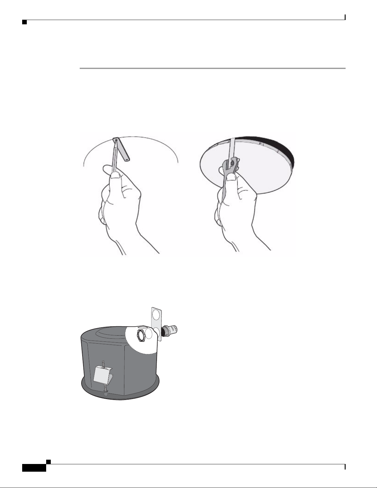
Step 1 Prepare the ceiling (see Figure 1-1):
Chapter 1 Installation
a. Locate the center point of the mounting location, and insert the compass tool into the ceiling.
b. Place the end of a pencil in the hole on the end of the compass tool, and draw a circle.
c. Cut out the circle.
Figure 1-1 Preparing the Ceiling
d. Attach a conduit fitting (not supplied), lock nut (not supplied), and safety chain bracket (see
Figure 1-2).
Figure 1-2 Attaching the Conduit Fitting, Lock Nut, and Safety Chain Bracket
Step 2 Install a safety chain/cable (not supplied), which will support up to 16 pounds (7.3 kg).
Step 3 Open the hinged door to the back box by pushing the tab lock toward the wall of the unit and lifting the
door open.
1-2
Cisco Video Surveillance IP PTZ Dome Camera User Guide, Cisco 2900 Series IP Dome
OL-24281-01
Chapter 1 Installation
Step 4 Pull the wiring into the back box through the conduit fitting.
Step 5 Connect all required wiring (see the “Wiring” section on page 1-4).
Step 6 Install the back box by compressing the spring clips and pushing the back box through the hole.
Step 7 Tighten the screws until you hear a clicking noise.
Pendant
Step 1 Install the mount for the pendant dome.
Step 2 Open the hinged door to the back box by pushing the tab lock towards the wall of the unit and lifting the
Step 3 Pull the wiring into the back box.
Step 4 Connect all required wiring (see the “Wiring” section on page 1-4).
Mounting
See the instructions supplied with the mount.
Note If the mount is outdoors, make sure it is properly sealed to keep moisture out.
door open.
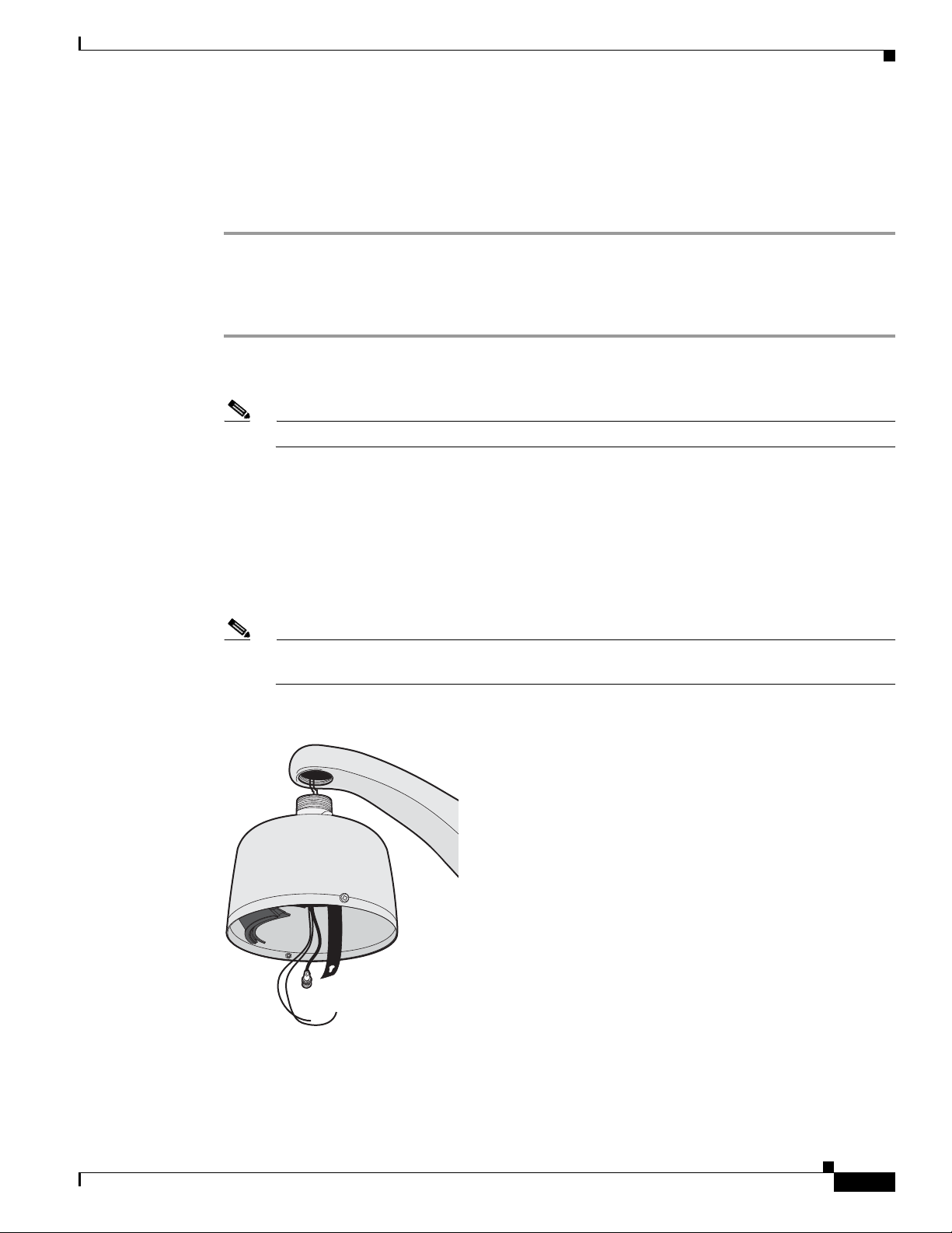
Step 5 Screw the back box onto the mount (see Figure 1-3).
If outdoors, apply thread compound (supplied) to the threads on the back box.
Note Thread compound must be applied. Not doing so may prevent the units from being separated in
the future.
Figure 1-3 Attaching the Pendant Back Box to the Mount
OL-24281-01
Cisco Video Surveillance IP PTZ Dome Camera User Guide, Cisco 2900 Series IP Dome
1-3
Mounting
+ -
Wiring
Chapter 1 Installation
Step 1 Open the hinged door to the back box by pushing the tab lock toward the wall of the unit and lifting the
door open (see
Figure 1-4 Black Box Door
Figure 1-4).
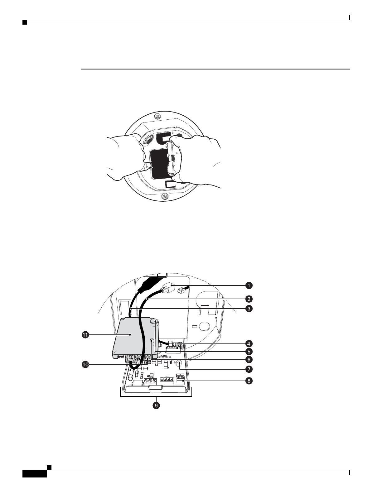
Step 2 Remove the TXB-N from the back box circuit board (see Figure 1-5):
a. Loosen the captive screw on the TXB-N.
b. Carefully unplug the TXB-N from the back box circuit board.
Figure 1-5 Removing the TXB-N
1-4
Cisco Video Surveillance IP PTZ Dome Camera User Guide, Cisco 2900 Series IP Dome
OL-24281-01
Chapter 1 Installation
VIDEO
UTP+ UTP-RX- RX+ TX+TX-PWR- PWR+GND
AUX2
GND
GND
NO
NC
COM
7
6
5
4
3
2
1
ALARMS
AUX1
Step 3 Connect the auxiliary, alarm, and other wiring to the back box circuit board (see Figure 1-6).
Mounting
1 RJ-45 Connector 7 Standoff
2 Ethernet Cable 8 UTP Connector
3 Video Coaxial Cable 9 Back Box Circuit Board
4 16-Pin Connector 10 Audio Connectors
5 Heat Sink Standoff 11 TXB-N
6 Captive Screw
Note Aux 1: Maximum 2 A at low voltage (<40 V).
Aux 2: Maximum 30 mA at 32 VDC.
If you are installing an environmental back box in a railway application, attach a ground wire
from the circuit board power connector to a structural ground using at least 18-gauge wire.
Figure 1-6 Connect the Wiring to the Circuit Board
OL-24281-01
Step 4 If you plan to use the audio functions, install your audio cables into the audio line-in and line-out
connectors on the TXB-N.
Cisco Video Surveillance IP PTZ Dome Camera User Guide, Cisco 2900 Series IP Dome
1-5
Mounting
Chapter 1 Installation
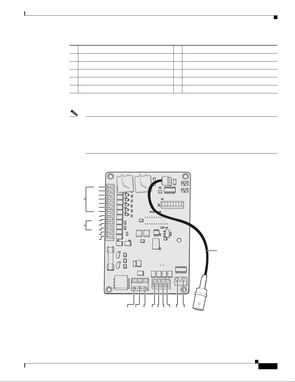
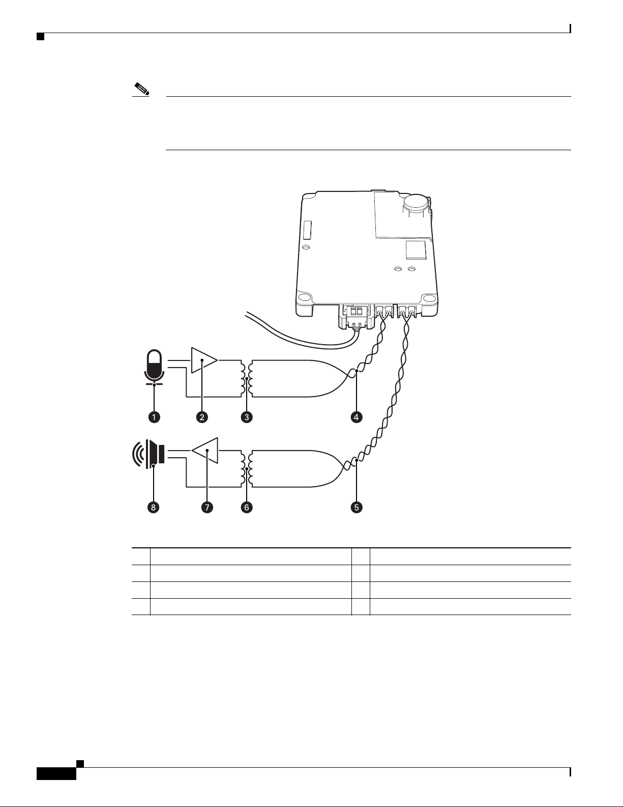
Note To take full advantage of the distance and noise immunity benefits of audio, you must use a
600-ohm impedance matching transformer and twisted pair cable (see Figure 1-7).
A stable power supply is required for optimal audio performance.
Figure 1-7 Connecting Audio to the TXB-N
1-6
1 Microphone 5 Line-Out Audio Twisted Pair Cable
2 Amplifier 6 600-Ohm Impedance Matching Transformer
3 600-Ohm Impedance Matching Transformer 7 Amplifier
4 Line-In Audio Twisted Pair Cable 8 Speaker
Step 5 Reinstall the TXB-N:
a. Plug the TXB-N into the 16-pin connector located on the back box circuit board.
b. Secure the TXB-N to the standoff on the circuit board using the captive screw on the TXB-N.
Step 6 Plug your network Ethernet cable into the RJ-45 connector on the TXB-N to connect the dome to your
existing network.
Cisco Video Surveillance IP PTZ Dome Camera User Guide, Cisco 2900 Series IP Dome
OL-24281-01
Chapter 1 Installation
Mounting
Warning
An electrical short in the back box may occur if the metal BNC connector on the video coaxial cable
is not completely covered by the protective boot.
Step 7 Perform one of the following options:
• View video using both analog and IP connections—Connect the video coaxial cable from the back
box circuit board to the coaxial cable coming in from the outside. Make sure that the BNC connector
is completely covered by the protective boot.
• View video using only the IP connection—Make sure that the BNC connector is completely covered
by the protective boot and is out of the way of the back box door.
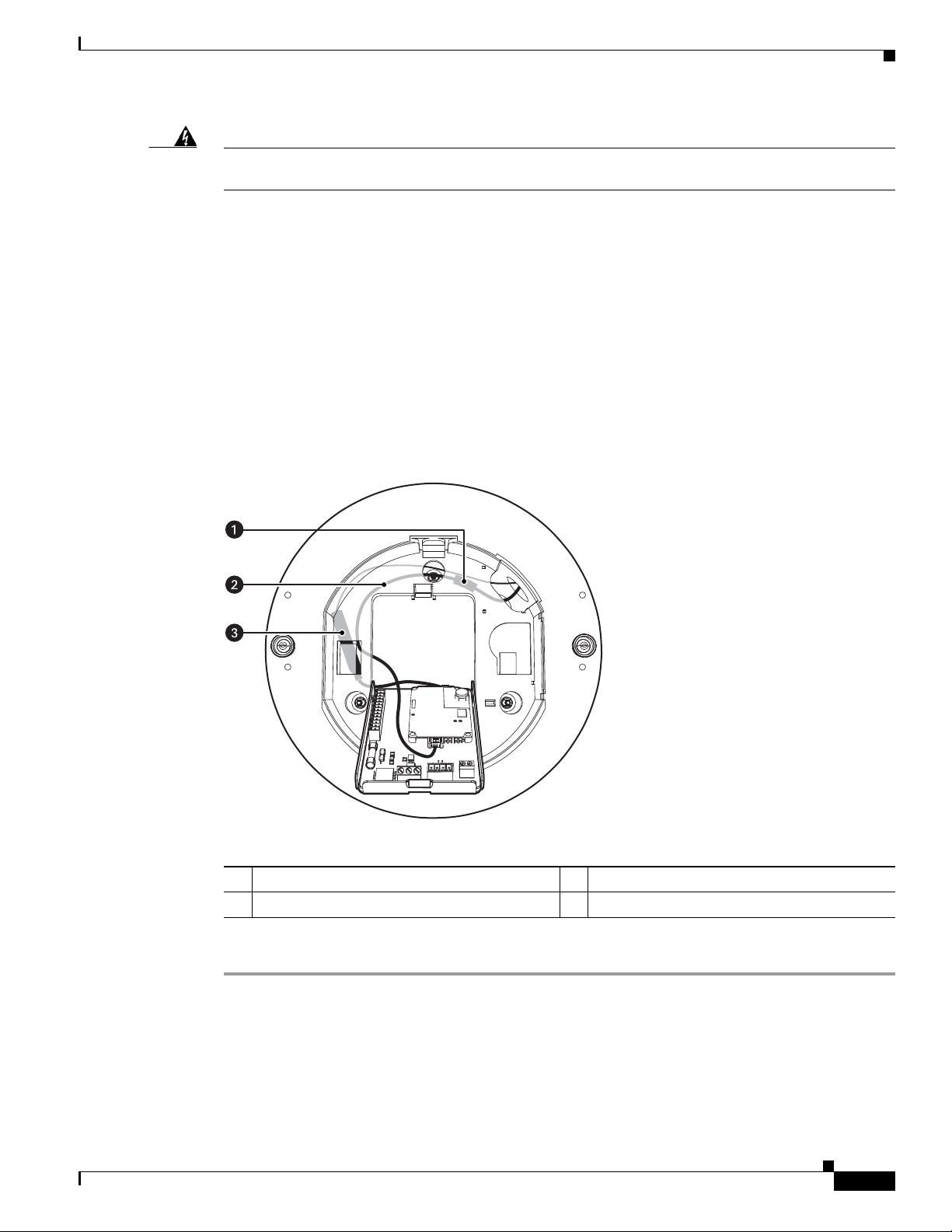
Step 8 Before closing the interconnect door, ensure that no wires are between the top of the heat sink standoff
and the back box (see
Figure 1-8).
Both the video coaxial cable and the Ethernet cable need to be routed carefully to ensure clearance for
the heat sink standoff.
Figure 1-8 Routing the Cables in the Back Box
OL-24281-01
1 RJ-45 Connector 3 Video Coaxial Cable
2 Ethernet Cable
Step 9 Close the interconnect door and snap the tab lock into place.
Cisco Video Surveillance IP PTZ Dome Camera User Guide, Cisco 2900 Series IP Dome
1-7

Installing the Dome Drive
Chapter 1 Installation
Table 1-1 shows the maximum distances for video coaxial cable types. A cable must meet these
requirements:
• 75-ohm impedance
• All-copper center conductor
• All-copper braided shield with 95 percent braid coverage
Ta b l e 1-1 Video Coaxial Cable Requirements
Cable Type Maximum Distance
RG59/U 750 ft (229 m)
RG6/U 1,000 ft (305 m)
RG11/U 1,500 ft (457 m)
Table 1-2 shows the recommended maximum distances for 24 VAC and 24 VDC applications, which are
calculated with a 10 percent voltage drop. (Ten percent is generally the maximum allowable voltage drop
for AC- or DC-powered devices.)
Ta b l e 1-2 24 VAC/24 VDC Wiring Distances
AC/DC
Wire Gauge
Total VA/
Total Watts
20 AWG (0.5 mm2) 18 AWG (1.05 mm2) 16 AWG (1.5 mm2) 14 AWG (2.5 mm2)
23VA/15 W 123 ft (38 m) 196 ft (60 m) 311 ft (95 m) 495 ft (151 m)
73 VA/65 W 39 ft (12 m) 62 ft (19 m) 98 ft (30 m) 156 ft (48 m)
Note Input power for the dome is 24 VAC or 24 VDC. Using 24 VAC input power, power consumption is 23
VA per dome for indoor models and 73 VA for outdoor models. Using 24 VDC input power, power
consumption is 0.7 A (15 W) for indoor models and 3 A (65 W) for outdoor models.
Use a 24 VAC transformer with the following minimum VA:
• 40 VA per dome—For indoor models (without heater)
• 100 VA per dome—For outdoor models (with heater)
Installing the Dome Drive
1-8
Step 1 If you will view video using both analog and IP connections, set the DIP switches on the top of the dome
drive (see
Figure 1-9).
For DIP switch settings, see the labels located on the top of the dome drive, or see the “Switch Settings”
section on page 1-11.
If you will view video using the IP connection, you do not need to set the DIP switches.
Cisco Video Surveillance IP PTZ Dome Camera User Guide, Cisco 2900 Series IP Dome
OL-24281-01
Chapter 1 Installation
Installing the Lower Dome
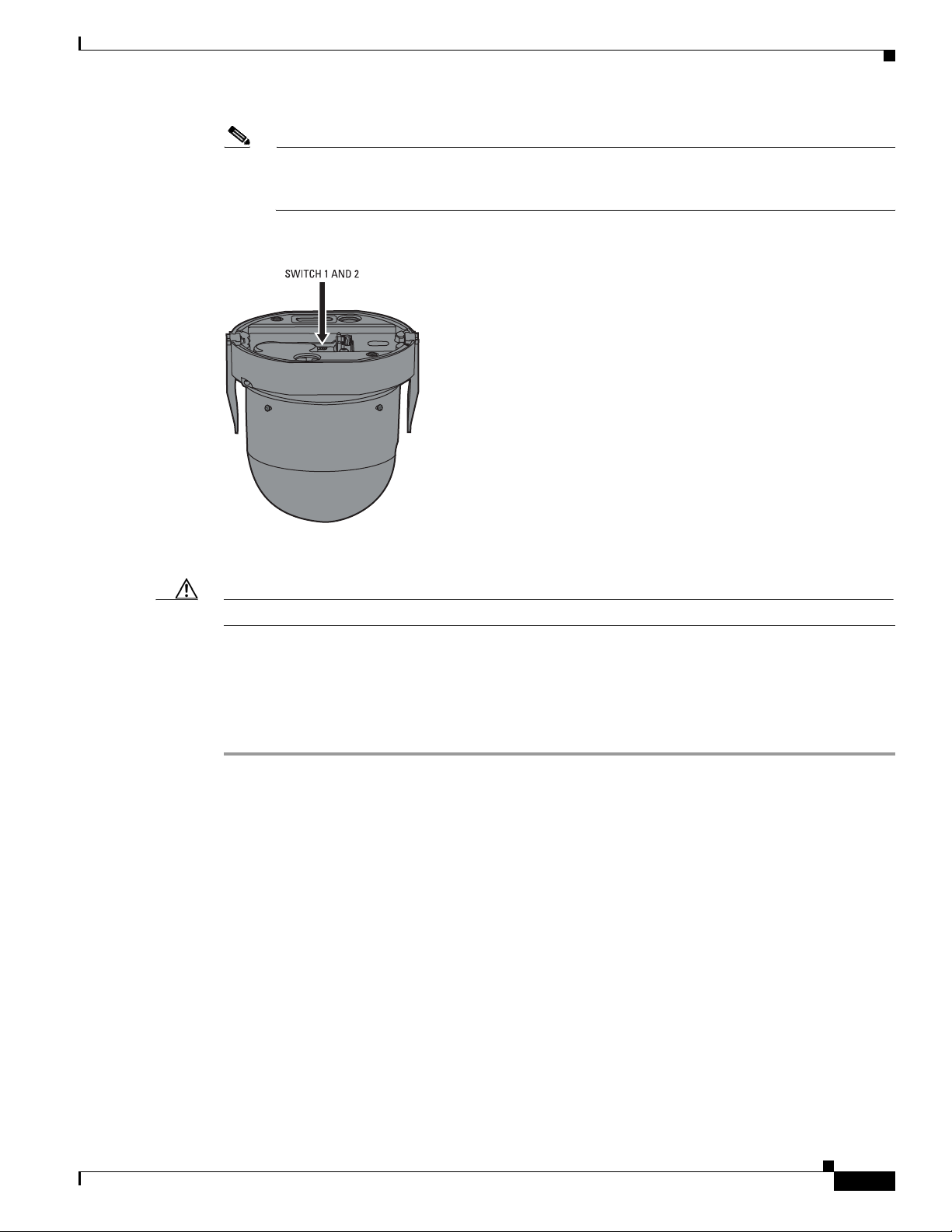
Note When connecting more than one Cisco 2900 Series IP Dome to a single controller, terminate the
unit farthest from the controller. To terminate the dome drive set the SW2-10 switch to the ON
position.
Figure 1-9 Setting the DIP Switches
Step 2 Install the dome drive.
Caution Improper installation of the dome drive can be dangerous and can seriously damage the equipment.
a. Align the blue and red tabs with the blue and red labels on the back box.
b. Push in the red tab and insert that side of the dome drive first.
c. Push in the blue tab and insert the dome drive into the back box the remainder of the way.
d. Continue pushing on the ends of the tabs until both sides click firmly into place.
Installing the Lower Dome
The following sections explain how to install the lower dome:
• In-Ceiling, page 1-10
• Pendant, page 1-10
OL-24281-01
Cisco Video Surveillance IP PTZ Dome Camera User Guide, Cisco 2900 Series IP Dome
1-9
Installing the Lower Dome
In-Ceiling
Step 1 Snap the clip on the end of the trim ring leash into the hole on the lip of the back box (see Figure 1-10).
Chapter 1 Installation
Figure 1-10 Installing the In-Ceiling Lower Dome
Pendant
Step 2 Snap the trim ring into the plastic snap washers on the mounting screws.
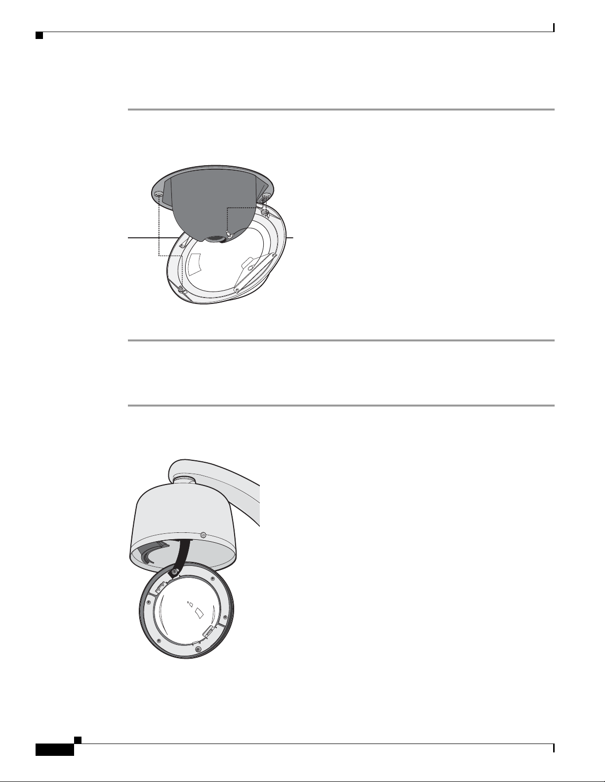
Step 1 Attach the back box leash to the lower dome (see Figure 1-11).
Figure 1-11 Attaching the Leash to the Pendant Lower Dome
1-10
Step 2 Push the lower dome into the back box.
Cisco Video Surveillance IP PTZ Dome Camera User Guide, Cisco 2900 Series IP Dome
OL-24281-01
Chapter 1 Installation
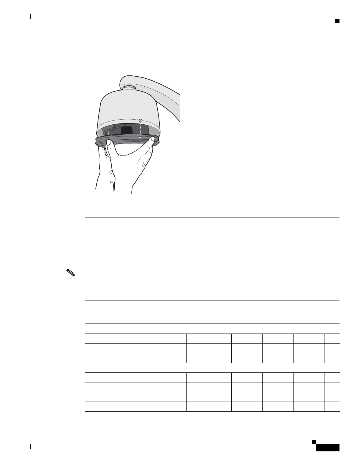
Step 3 Tighten the captive Phillips pan head screws to secure the lower dome (see Figure 1-12).
Switch Settings
Figure 1-12 Installing the Pendant Lower Dome
Switch Settings
Table 1-3 shows SW2 switch settings.
Note If you are using Pelco D-type or Pelco P-type control, your system may not operate if the baud rate and
address switches are not set correctly. The switches are set at the factory using the defaults for
Pelco D-type control (2400 baud and address 1).
Ta b l e 1-3 Switch Settings for SW2
Special Systems
Switch Number 1 2 3 4 5 6 7 8 9 10
AD-32 Preset System ON
CM9502 Setting ON
Serial Port Settings
Switch Number 1 2 3 4 5 6 7 8 9 10
RS422 OFF OFF
RS485, 4-Wire OFF ON
RS485, 2-Wire ON ON
OL-24281-01
Cisco Video Surveillance IP PTZ Dome Camera User Guide, Cisco 2900 Series IP Dome
1-11
Switch Settings
Chapter 1 Installation
Table 1-3 Switch Settings for SW2 (continued)
Pelco D or Pelco P Protocol Baud Rate
Switch Number 1 2 3 4 5 6 7 8 9 10
2400 Baud (Default for D-type Control) OFF OFF OFF
4800 Baud (Default for P-type Control) ON OFF OFF
9600 Baud OFF ON OFF
Video Cable Type
Switch Number 1 2 3 4 5 6 7 8 9 10
Coaxial Cable OFF
Dome Termination
Switch Number 1 2 3 4 5 6 7 8 9 10
Terminated ON
Not Terminated OFF
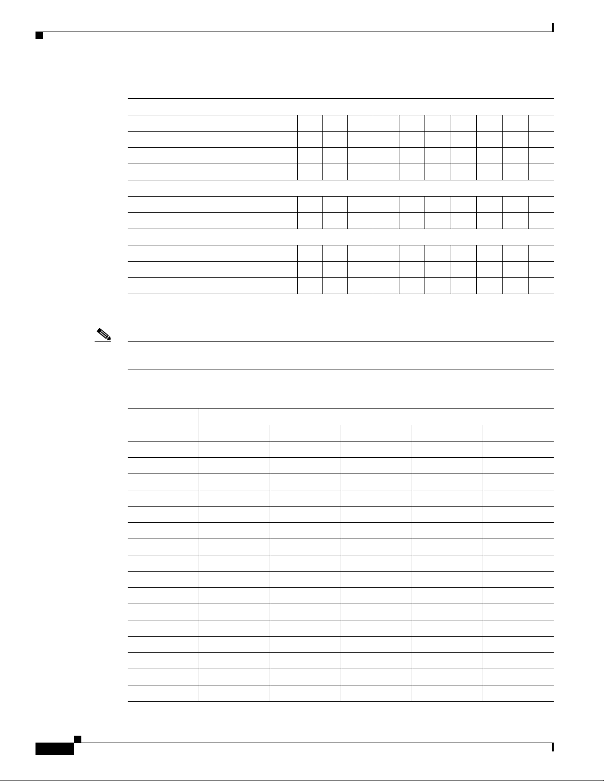
Table 1-4 shows SW1 switch settings for Pelco P-Type control.
Note For Coaxitron controls, SW1 is not used; set all switches to OFF. For Pelco D-type control systems, see
Table 1-5 on page 1-13.
Ta b l e 1-4 Switch Settings for SW1, Pelco P-Type Control
Switch Setting
Address
SW1-1 SW1-2 SW1-3 SW1-4 SW1-5
1 OFF OFF OFF OFF OFF
2 ON OFF OFF OFF OFF
3 OFF ON OFF OFF OFF
4 ON ON OFF OFF OFF
5 OFF OFF ON OFF OFF
6 ON OFF ON OFF OFF
7 OFF ON ON OFF OFF
8 ON ON ON OFF OFF
9 OFF OFF OFF ON OFF
10 ON OFF OFF ON OFF
11 OFF ON OFF ON OFF
12 ON ON OFF ON OFF
13 OFF OFF ON ON OFF
14 ON OFF ON ON OFF
15 OFF ON ON ON OFF
16 ON ON ON ON OFF
1-12
Cisco Video Surveillance IP PTZ Dome Camera User Guide, Cisco 2900 Series IP Dome
OL-24281-01
Chapter 1 Installation
Switch Settings
Table 1-4 Switch Settings for SW1, Pelco P-Type Control (continued)
Switch Setting
Address
17 OFF OFF OFF OFF ON
18 ON OFF OFF OFF ON
19 OFF ON OFF OFF ON
20 ON ON OFF OFF ON
21 OFF OFF ON OFF ON
22 ON OFF ON OFF ON
23 OFF ON ON OFF ON
24 ON ON ON OFF ON
25 OFF OFF OFF ON ON
26 ON OFF OFF ON ON
27 OFF ON OFF ON ON
28 ON ON OFF ON ON
29 OFF OFF ON ON ON
30 ON OFF ON ON ON
31 OFF ON ON ON ON
32 ON ON ON ON ON
SW1-1 SW1-2 SW1-3 SW1-4 SW1-5
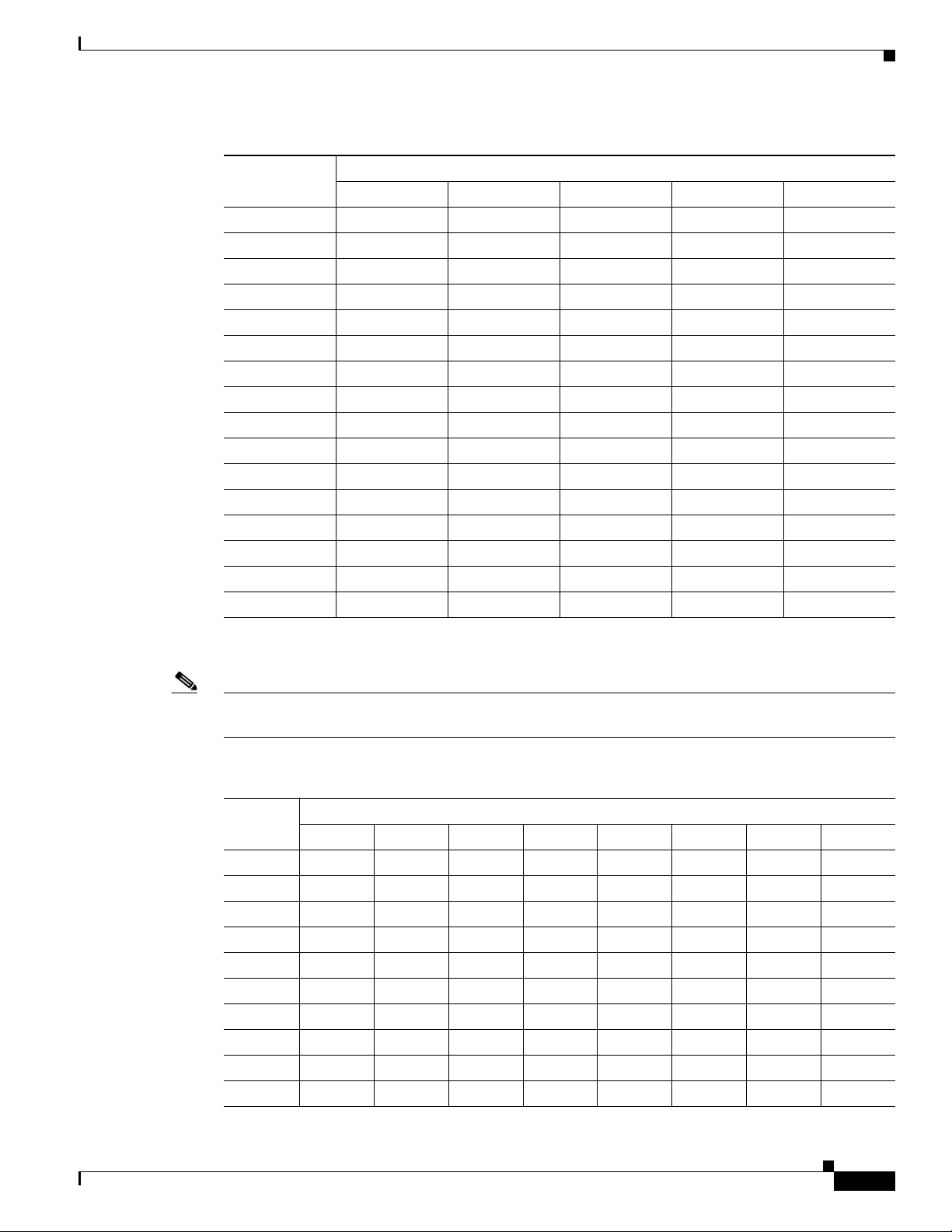
Table 1-5 shows SW1 switch settings for Pelco D-Type control.
Note For Coaxitron controls, SW1 is not used; set all switches to OFF. For Pelco P-type control systems, see
Table 1-4 on page 1-12.
Ta b l e 1-5 Switch Settings for SW1, Pelco D-Type Control
Switch Setting
Address
SW1-1 SW1-2 SW1-3 SW1-4 SW1-5 SW1-6 SW1-7 SW1-8
1 ON OFF OFF OFF OFF OFF OFF OFF
2 OFF ON OFF OFF OFF OFF OFF OFF
3 ON ON OFF OFF OFF OFF OFF OFF
4 OFF OFF ON OFF OFF OFF OFF OFF
5 ON OFF ON OFF OFF OFF OFF OFF
6 OFF ON ON OFF OFF OFF OFF OFF
7 ON ON ON OFF OFF OFF OFF OFF
8 OFF OFF OFF ON OFF OFF OFF OFF
9 ON OFF OFF ON OFF OFF OFF OFF
10 OFF ON OFF ON OFF OFF OFF OFF
OL-24281-01
Cisco Video Surveillance IP PTZ Dome Camera User Guide, Cisco 2900 Series IP Dome
1-13

Switch Settings
Chapter 1 Installation
Table 1-5 Switch Settings for SW1, Pelco D-Type Control (continued)
Switch Setting
Address
11 ON ON OFF ON OFF OFF OFF OFF
12 OFF OFF ON ON OFF OFF OFF OFF
13 ON OFF ON ON OFF OFF OFF OFF
14 OFF ON ON ON OFF OFF OFF OFF
15 ON ON ON ON OFF OFF OFF OFF
16 OFF OFF OFF OFF ON OFF OFF OFF
17 ON OFF OFF OFF ON OFF OFF OFF
18 OFF ON OFF OFF ON OFF OFF OFF
19 ON ON OFF OFF ON OFF OFF OFF
20 OFF OFF ON OFF ON OFF OFF OFF
21 ON OFF ON OFF ON OFF OFF OFF
22 OFF ON ON OFF ON OFF OFF OFF
23 ON ON ON OFF ON OFF OFF OFF
24 OFF OFF OFF ON ON OFF OFF OFF
25 ON OFF OFF ON ON OFF OFF OFF
26 OFF ON OFF ON ON OFF OFF OFF
27 ON ON OFF ON ON OFF OFF OFF
28 OFF OFF ON ON ON OFF OFF OFF
29 ON OFF ON ON ON OFF OFF OFF
30 OFF ON ON ON ON OFF OFF OFF
31 ON ON ON ON ON OFF OFF OFF
32 OFF OFF OFF OFF OFF ON OFF OFF
33 ON OFF OFF OFF OFF ON OFF OFF
34 OFF ON OFF OFF OFF ON OFF OFF
35 ON ON OFF OFF OFF ON OFF OFF
36 OFF OFF ON OFF OFF ON OFF OFF
37 ON OFF ON OFF OFF ON OFF OFF
38 OFF ON ON OFF OFF ON OFF OFF
39 ON ON ON OFF OFF ON OFF OFF
40 OFF OFF OFF ON OFF ON OFF OFF
41 ON OFF OFF ON OFF ON OFF OFF
42 OFF ON OFF ON OFF ON OFF OFF
43 ON ON OFF ON OFF ON OFF OFF
44 OFF OFF ON ON OFF ON OFF OFF
45 ON OFF ON ON OFF ON OFF OFF
SW1-1 SW1-2 SW1-3 SW1-4 SW1-5 SW1-6 SW1-7 SW1-8
1-14
Cisco Video Surveillance IP PTZ Dome Camera User Guide, Cisco 2900 Series IP Dome
OL-24281-01

Chapter 1 Installation
Switch Settings
Table 1-5 Switch Settings for SW1, Pelco D-Type Control (continued)
Switch Setting
Address
46 OFF ON ON ON OFF ON OFF OFF
47 ON ON ON ON OFF ON OFF OFF
48 OFF OFF OFF OFF ON ON OFF OFF
49 ON OFF OFF OFF ON ON OFF OFF
50 OFF ON OFF OFF ON ON OFF OFF
51 ON ON OFF OFF ON ON OFF OFF
52 OFF OFF ON OFF ON ON OFF OFF
53 ON OFF ON OFF ON ON OFF OFF
54 OFF ON ON OFF ON ON OFF OFF
55 ON ON ON OFF ON ON OFF OFF
56 OFF OFF OFF ON ON ON OFF OFF
57 ON OFF OFF ON ON ON OFF OFF
58 OFF ON OFF ON ON ON OFF OFF
59 ON ON OFF ON ON ON OFF OFF
60 OFF OFF ON ON ON ON OFF OFF
61 ON OFF ON ON ON ON OFF OFF
62 OFF ON ON ON ON ON OFF OFF
63 ON ON ON ON ON ON OFF OFF
64 OFF OFF OFF OFF OFF OFF ON OFF
65 ON OFF OFF OFF OFF OFF ON OFF
66 OFF ON OFF OFF OFF OFF ON OFF
67 ON ON OFF OFF OFF OFF ON OFF
68 OFF OFF ON OFF OFF OFF ON OFF
69 ON OFF ON OFF OFF OFF ON OFF
70 OFF ON ON OFF OFF OFF ON OFF
71 ON ON ON OFF OFF OFF ON OFF
72 OFF OFF OFF ON OFF OFF ON OFF
73 ON OFF OFF ON OFF OFF ON OFF
74 OFF ON OFF ON OFF OFF ON OFF
75 ON ON OFF ON OFF OFF ON OFF
76 OFF OFF ON ON OFF OFF ON OFF
77 ON OFF ON ON OFF OFF ON OFF
78 OFF ON ON ON OFF OFF ON OFF
79 ON ON ON ON OFF OFF ON OFF
80 OFF OFF OFF OFF ON OFF ON OFF
SW1-1 SW1-2 SW1-3 SW1-4 SW1-5 SW1-6 SW1-7 SW1-8
OL-24281-01
Cisco Video Surveillance IP PTZ Dome Camera User Guide, Cisco 2900 Series IP Dome
1-15

Switch Settings
Chapter 1 Installation
Table 1-5 Switch Settings for SW1, Pelco D-Type Control (continued)
Switch Setting
Address
81 ON OFF OFF OFF ON OFF ON OFF
82 OFF ON OFF OFF ON OFF ON OFF
83 ON ON OFF OFF ON OFF ON OFF
84 OFF OFF ON OFF ON OFF ON OFF
85 ON OFF ON OFF ON OFF ON OFF
86 OFF ON ON OFF ON OFF ON OFF
87 ON ON ON OFF ON OFF ON OFF
88 OFF OFF OFF ON ON OFF ON OFF
89 ON OFF OFF ON ON OFF ON OFF
90 OFF ON OFF ON ON OFF ON OFF
91 ON ON OFF ON ON OFF ON OFF
92 OFF OFF ON ON ON OFF ON OFF
93 ON OFF ON ON ON OFF ON OFF
94 OFF ON ON ON ON OFF ON OFF
95 ON ON ON ON ON OFF ON OFF
96 OFF OFF OFF OFF OFF ON ON OFF
97 ON OFF OFF OFF OFF ON ON OFF
98 OFF ON OFF OFF OFF ON ON OFF
99 ON ON OFF OFF OFF ON ON OFF
100 OFF OFF ON OFF OFF ON ON OFF
101 ON OFF ON OFF OFF ON ON OFF
102 OFF ON ON OFF OFF ON ON OFF
103 ON ON ON OFF OFF ON ON OFF
104 OFF OFF OFF ON OFF ON ON OFF
105 ON OFF OFF ON OFF ON ON OFF
106 OFF ON OFF ON OFF ON ON OFF
107 ON ON OFF ON OFF ON ON OFF
108 OFF OFF ON ON OFF ON ON OFF
109 ON OFF ON ON OFF ON ON OFF
110 OFF ON ON ON OFF ON ON OFF
111 ON ON ON ON OFF ON ON OFF
112 OFF OFF OFF OFF ON ON ON OFF
113 ON OFF OFF OFF ON ON ON OFF
114 OFF ON OFF OFF ON ON ON OFF
115 ON ON OFF OFF ON ON ON OFF
SW1-1 SW1-2 SW1-3 SW1-4 SW1-5 SW1-6 SW1-7 SW1-8
1-16
Cisco Video Surveillance IP PTZ Dome Camera User Guide, Cisco 2900 Series IP Dome
OL-24281-01

Chapter 1 Installation
Switch Settings
Table 1-5 Switch Settings for SW1, Pelco D-Type Control (continued)
Switch Setting
Address
116 OFF OFF ON OFF ON ON ON OFF
117 ON OFF ON OFF ON ON ON OFF
118 OFF ON ON OFF ON ON ON OFF
119 ON ON ON OFF ON ON ON OFF
120 OFF OFF OFF ON ON ON ON OFF
121 ON OFF OFF ON ON ON ON OFF
122 OFF ON OFF ON ON ON ON OFF
123 ON ON OFF ON ON ON ON OFF
124 OFF OFF ON ON ON ON ON OFF
125 ON OFF ON ON ON ON ON OFF
126 OFF ON ON ON ON ON ON OFF
127 ON ON ON ON ON ON ON OFF
128 OFF OFF OFF OFF OFF OFF OFF ON
129 ON OFF OFF OFF OFF OFF OFF ON
130 OFF ON OFF OFF OFF OFF OFF ON
131 ON ON OFF OFF OFF OFF OFF ON
132 OFF OFF ON OFF OFF OFF OFF ON
133 ON OFF ON OFF OFF OFF OFF ON
134 OFF ON ON OFF OFF OFF OFF ON
135 ON ON ON OFF OFF OFF OFF ON
136 OFF OFF OFF ON OFF OFF OFF ON
137 ON OFF OFF ON OFF OFF OFF ON
138 OFF ON OFF ON OFF OFF OFF ON
139 ON ON OFF ON OFF OFF OFF ON
140 OFF OFF ON ON OFF OFF OFF ON
141 ON OFF ON ON OFF OFF OFF ON
142 OFF ON ON ON OFF OFF OFF ON
143 ON ON ON ON OFF OFF OFF ON
144 OFF OFF OFF OFF ON OFF OFF ON
145 ON OFF OFF OFF ON OFF OFF ON
146 OFF ON OFF OFF ON OFF OFF ON
147 ON ON OFF OFF ON OFF OFF ON
148 OFF OFF ON OFF ON OFF OFF ON
149 ON OFF ON OFF ON OFF OFF ON
150 OFF ON ON OFF ON OFF OFF ON
SW1-1 SW1-2 SW1-3 SW1-4 SW1-5 SW1-6 SW1-7 SW1-8
OL-24281-01
Cisco Video Surveillance IP PTZ Dome Camera User Guide, Cisco 2900 Series IP Dome
1-17

Switch Settings
Chapter 1 Installation
Table 1-5 Switch Settings for SW1, Pelco D-Type Control (continued)
Switch Setting
Address
151 ON ON ON OFF ON OFF OFF ON
152 OFF OFF OFF ON ON OFF OFF ON
153 ON OFF OFF ON ON OFF OFF ON
154 OFF ON OFF ON ON OFF OFF ON
155 ON ON OFF ON ON OFF OFF ON
156 OFF OFF ON ON ON OFF OFF ON
157 ON OFF ON ON ON OFF OFF ON
158 OFF ON ON ON ON OFF OFF ON
159 ON ON ON ON ON OFF OFF ON
160 OFF OFF OFF OFF OFF ON OFF ON
161 ON OFF OFF OFF OFF ON OFF ON
162 OFF ON OFF OFF OFF ON OFF ON
163 ON ON OFF OFF OFF ON OFF ON
164 OFF OFF ON OFF OFF ON OFF ON
165 ON OFF ON OFF OFF ON OFF ON
166 OFF ON ON OFF OFF ON OFF ON
167 ON ON ON OFF OFF ON OFF ON
168 OFF OFF OFF ON OFF ON OFF ON
169 ON OFF OFF ON OFF ON OFF ON
170 OFF ON OFF ON OFF ON OFF ON
171 ON ON OFF ON OFF ON OFF ON
172 OFF OFF ON ON OFF ON OFF ON
173 ON OFF ON ON OFF ON OFF ON
174 OFF ON ON ON OFF ON OFF ON
175 ON ON ON ON OFF ON OFF ON
176 OFF OFF OFF OFF ON ON OFF ON
177 ON OFF OFF OFF ON ON OFF ON
178 OFF ON OFF OFF ON ON OFF ON
179 ON ON OFF OFF ON ON OFF ON
180 OFF OFF ON OFF ON ON OFF ON
181 ON OFF ON OFF ON ON OFF ON
182 OFF ON ON OFF ON ON OFF ON
183 ON ON ON OFF ON ON OFF ON
184 OFF OFF OFF ON ON ON OFF ON
185 ON OFF OFF ON ON ON OFF ON
SW1-1 SW1-2 SW1-3 SW1-4 SW1-5 SW1-6 SW1-7 SW1-8
1-18
Cisco Video Surveillance IP PTZ Dome Camera User Guide, Cisco 2900 Series IP Dome
OL-24281-01
 Loading...