


Cisco Systems 102090P Manual
GETTING STARTED GUIDE
Cisco Aironet 1530 Series Outdoor Mesh Access Points
INCLUDING LICENSE AND WARRANTY
Revised July 05, 2013
P/N: 78-19963-02
1About this Guide
2Introduction to the Access Point
3Unpacking the Access Point
4Radio Configuration
5Becoming Familiar With the Access Point
6AP Pole/Wall Mount
7Preparing the Access Point
8Deploying the Access Point
9In Case of Difficulty
10Declarations of Conformity and Regulatory Information
11Warranty

1 About this Guide
This guide is designed to familiarize you with your Cisco Aironet 1530 Series Outdoor Mesh Access Point and prepare it for use in your wireless network. For in-depth details on configuring a wireless mesh network, please see:
• Cisco Mesh Networking Solution Deployment Guide
Detailed configuration information can also be found in the Cisco wireless LAN controller documentation for the controller and software release you are using. These documents are available on Cisco.com. Follow these steps to access these documents:
Step 1 Browse to http://www.cisco.com.
Step 2 Click Support. A pop-up window appears.
Step 3 Click Wireless under Select a Product Name. The Select Your Product or Technology page appears.
Step 4 Click Wireless > Outdoor Wireless.
Step 5 Click Cisco AP 1530 Series in the Search for a Specific Product field. The Cisco 1530 Series Introduction page appears.
Step 6 Choose the appropriate link for the documentation you want to view or download.
General Safety Guidelines
Warnings
Safety warnings appear throughout this guide in procedures that may harm you if performed incorrectly. A warning symbol precedes each warning statement. The warnings below are general warnings that are applicable to the entire guide. Specific warnings are included in the sections to which they apply.
Warning |
This warning symbol means danger. You are in a situation that could cause bodily injury. |
|
Before you work on any equipment, be aware of the hazards involved with electrical |
|
circuitry and be familiar with standard practices for preventing accidents. Use the |
|
statement number provided at the end of each warning to locate its translation in the |
|
translated safety warnings that accompanied this device. |
|
Statement 1071 |
|
SAVE THESE INSTRUCTIONS |
|
|
2

Warning
Warning
Warning
Warning
Warning
Warning
There is the danger of explosion if the battery is replaced incorrectly. Replace the battery only with the same or equivalent type recommended by the manufacturer. Dispose of used batteries according to the manufacturer’s instructions. Statement 1015
Do not operate the unit near unshielded blasting caps or in an explosive environment unless the device has been modified to be especially qualified for such use.
Statement 364
This equipment must be externally grounded using a customer-supplied ground wire before power is applied. Contact the appropriate electrical inspection authority or an electrician if you are uncertain that suitable grounding is available.
Statement 366
Read the installation instructions before connecting the system to the power source.
Statement 1004
Only trained and qualified personnel should be allowed to install, replace, or service this equipment. Statement 1030
Ultimate disposal of this product should be handled according to all national laws and regulations. Statement 1040
3
2 Introduction to the Access Point
The Cisco Aironet 1530 Series Outdoor Mesh Access Point (hereafter called the access point or AP) is a rugged outdoor access point designed for service in mesh networks. The 1530 series leverages 802.11n technology with integrated radio and internal/external antennas.
The 1530 AP series contains a 2.4 GHz and 5 GHz radio with an option to configure in centralized, Flexconnect, or mesh mode. The 2.4 GHz radios are used primarily for local access, and the 5 GHz radios can be configured for both local access and/or wireless backhaul in the Mesh mode.
The access point is a standalone unit that can be wall, pole or tower mounted. The access point can also operate as a relay node for other access points not directly connected to a wired network. Intelligent wireless routing is provided by the Adaptive Wireless Path Protocol (AWPP). This enables each access point to identify its neighbors and intelligently choose the optimal path to the wired network by calculating the cost of each path in terms of signal strength and the number of hops required to get to a controller. The access point is configured, monitored, and operated through a Cisco wireless LAN controller (WLC), referred to as a controller in this document. The WLC is described in the appropriate Cisco Wireless LAN Controller Configuration Guide. The Cisco Mesh Networking Solution Deployment Guide describes how to plan and initially configure the Cisco mesh network, which supports wireless point-to-multipoint mesh deployments. The controllers use a browser-based management system, a command-line interface (CLI), or the Cisco Prime Infrastructure (CIP) network management system to manage the controller and the associated access points.
4

3 Unpacking the Access Point
Follow these steps to unpack the access point:
Step 1 Open the shipping container and carefully remove the contents.
Step 2 Return all packing materials to the shipping container and save it.
Step 3 Ensure that all items listed in the “Package Contents” section on page 5 are included in the shipment. Check each item for damage. If any item is damaged or missing, notify your authorized Cisco sales representative.
Package Contents
Each access point package contains the following items:
•One 1530 series access point
•Two-pin DC power connector
•Ground lug (Panduit PLCD6-10A-L) and screws with lock washers
•Plastic cable gland and rubber seal
•Weatherization tape and anti-corrosion sealant
•Cisco product documentation and translated safety warnings
Optional Equipment
Depending on what you ordered, the following optional equipment may be part of your shipment:
External antennas, depending on which ones you purchased (see “1532E Antennas” section on page 6 for more information).
•Wall/Pole mount bracket, available as an option or a spare (AIR-ACC1530-PMK1[=])
•Wall/Pole mount bracket with tilt mechanism, spare only (AIR-ACC1530-PMK2=)
•AP cover / Solar Shield for 1532, spare only (AIR-ACC1530-CVR=)
•AC/DC power adapter, spare only (AIR-PWRADPT-1530=)
•Spare Parts kit containing extra cable glands, power connector, ground lug, etc. (AIR-ACC1530-KIT1=)
5
Antennas
1532I Antennas
• Internal (3/5 dBi)
1532E Antennas
Dual Band Antennas
•AIR-ANT2547V-N (4/7 dBi, OMNI)
•AIR-ANT2547VG-N same as above but gray in color (4/7dBi, OMNI)
•AIR-ANT2588P3M-N= (8/8 dBi, dual polarized patch)
Mono Band Antennas
2.4 GHz
•AIR-ANT2450V-N= (5 dBi, OMNI)
•AIR-ANT2480V-N= (8 dBi, OMNI)
•AIR-ANT2413P2M-N= (13 dBi, dual polarized patch)
5GHz
•AIR-ANT5180V-N (8 dBi, OMNI)
•AIR-ANT5114P2M-N= (14 dBi, dual polarized patch)
Non-Cisco Antennas
Cisco does not support any third-party antennas. RF connectivity and compliance of third party antennas is the customer’s responsibility. Cisco does not recommend any third-party antennas, and Cisco Technical Assistance Center will not be able to provide any support for third-party antennas. Cisco’s FCC Part 15 compliance is only guaranteed with Cisco antennas or antennas that are of the same design and gain as Cisco antennas.
6
4 Radio Configuration
There are two radio configurations for the 1532 AP radio, the 2 GHz MIMO radio and the 5 GHz MIMO radio. The 2GHz MIMO radio operates in 2.4 GHz ISM band. It supports up to channels 13 channels.The 5GHz MIMO radio operates in the UNII-2 band (5.25 – 5.35 GHz), the UNII-2 Extended/ETSI band (5.47 – 5.725 GHz), and the upper ISM band (5.725 – 5.875 GHz). it supports up to 16 channels.
Refer to the data sheet for the number of channels that are supported for each regulatory domain. For information on the regulatory domains see “Regulatory Domains” section on page 43.
The configurations for the two 1532 radios are:
•Dual Band
•Single Band
Dual Band
Single Band
2.4 GHz Antennas
5 GHz Antennas
7
5 Becoming Familiar With the Access Point
The following illustrations show the access point connections. Before you begin the installation process, use these illustrations to familiarize yourself with the access point.
Note The illustrations show all available connections for the configuration ordered. Unused connections are capped with rubber seals to ensure the watertight integrity of the access point. Liquid tight connectors and rubber seals are provided for all ports, which can be installed prior to or after deploying the access point.
Figure 1 and Figure 3 shows the access point bottom and top connectors for model AP 1532I. Figure 2 shows the bottom connectors for model AP 1532E. Figure 4 and Figure 5 show the left and right side connectors for both AP 1532 models.
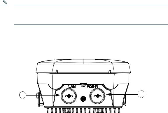
Figure 1 Access Point Bottom Connectors - AP 1532I
347850
1 |
LAN port (covered) |
2 |
PoE-in port (covered) |
|
|
|
|
8

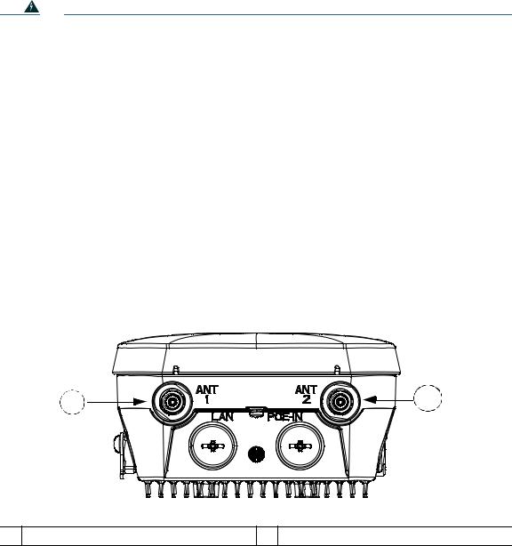
Figure 2 Access Point Bottom Connectors - AP 1532E
1 |
2 |
|
3 |
4 |
|
347848 |
1 |
Antenna port 1 |
2 |
Antenna port 2 |
|
|
|
|
3 |
LAN port (covered) |
4 |
PoE-in port (covered) |
|
|
|
|
Figure 3 Access Point Top Connectors - AP 1532E
1 |
2 |
|
347847 |
1 Antenna port 4 (covered) |
2 Antenna port 3 (covered) |
9
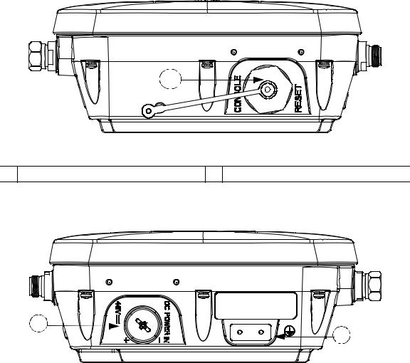
Figure 4 Access Point Left Side Connectors - Both AP 1532 Models
347845
1
1 Console Port (covered)
Figure 5 Access Point DC Power Connector and Ground Lug (Both AP 1532 Models)
347846
1 |
DC power port |
2 |
Ground lug location |
|
|
|
|
10
Radio Operation and Antennas
AP 1532I
The AP 1532I uses an Integrated Low Profile Dual-Band 2.4/5 GHz Dipole Antenna Array. The antenna contains an array of three dual-band dipole antennas. The three dipole antennas are contained within this single radome, thereby greatly reducing the antennas visual footprint, and greatly reducing the possibility of snagging the antenna on the cable bundle, the RF cable, or test cables. The antennas operate over both 2.4 GHz and 5.25 – 5.85 GHz bands. Each of the three dipole antennas is a dual-band antenna, covering both the 2.4 – 2.483 GHz band, and the 5.25 – 5.85 GHz bands. The antenna have a peak gain of about 2 dBi at 2.4 GHz and 4 dBi at 5 GHz. The antenna unit is gray weatherproof radome for outdoor operation.
The 1532I access point 802.11b/g/n radio is used primarily for local access and its 802.11a/n radio for wireless backhaul in the Mesh.
The 2 GHz b/g/n radio operates in 2.4 GHz ISM band. It supports channels 1-11 in US, 1-13 in Europe, and 1-13 in Japan. It has three transmitters with a maximum total output power of 29dBm for 802.11b/g/n operation. Output power is configurable to 5 levels. It has three receivers that enables maximum-ratio combining (MRC).
The 5GHz a/n radio operates in the UNII-2 band (5.25 - 5.35 GHz), UNII-2 Extended/ETSI band (5.47 - 5.725 GHz), and the upper ISM band (5.725 - 5.850 GHz). It has two transmitters with a maximum total output power of 29 dBm for UNII-2 and Extended/ETSI bands for the A-domain. The total maximum output power for the upper ISM band is 28 dBm for A-domain. Tx power settings will change depending on the regulatory domain. Output power is configurable for 5 power levels in 3 dB steps. Its three receivers enables maximum-ratio combining (MRC).
The 1532I access point is equipped with three integrated dual-band antennas with 3 dBi gain at 2 GHz and 5 dBi at 5 GHz.
Warning |
In order to comply with radio frequency (RF) exposure limits, the antennas up to 8 dBi |
|
|
|
gain for this product should be placed no less than 20 cm (8") from your body or nearby |
|
|
persons. This distance shall be increased to 50 cm (20") with antennas that have gain |
|
|
between 8 and 14 dBi. Statement 339 |
|
|
|
|
|
|
Warning |
Do not locate the antenna near overhead power lines or other electric light or power |
|
|
|
circuits, or where it can come into contact with such circuits. When installing the |
|
|
antenna, take extreme care not to come into contact with such circuits, because they |
|
|
may cause serious injury or death. For proper installation and grounding of the antenna, |
|
|
please refer to national and local codes (for example, U.S.:NFPA 70, National Electrical |
|
|
Code, Article 810, Canada: Canadian Electrical Code, Section 54). Statement 1052 |
|
|
|
11
Warning |
Only trained and qualified personnel should be allowed to install, replace, or service this |
|
equipment. |
|
Statement 1030 |
|
|
AP 1532E
The 1532E is equipped with two N-type radio frequency (RF) connectors (antenna ports 1 and 2) on the bottom of the unit for external antennas to support multiple input multiple output (MIMO) operation in dual-band mode, as shown in Figure 6. The 1532E must always be operated with the two external antennas attached. When using the Cisco Aironet AIR-ANT2547V-N Dual-Band Omnidirectional Antenna, the 2.4- and 5-GHz antennas connect directly to the access point, as shown in Figure 7. If the antennas are remotely located, an appropriate low loss RF coax cable should be used.
The 1532E access point are equipped with 4 N-type radio frequency (RF) connectors (antenna ports 1 and 2 on the bottom of the unit for 2 GHz and antenna ports 3 and 4 on the top of the unit for 5 GHz) for external antennas to support multiple input multiple output (MIMO) operation. The antenna ports located of top of the 1532E are shown in Figure 3. The 1532E must always be operated with the appropriate external antennas attached.
Ports 1 and 2 can be used for Dual Band operation with a software configuration.
Figure 6 Access Point Bottom External Antenna Connectors - AP 1532E
347848
1 N-Type Connector - Antenna port 4 (Tx/Rx) 2 N-Type Connector - Antenna port 6 (Tx/Rx)
12
Antenna Mounting Configurations
The selection of the antenna is determined in the configuration of the product. The 1532E antennas can be mounted on a wall, pole and/or tower mounted. See Antennas, page 6 for a list of supported antennas.
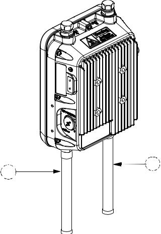
Figure 7 Access Point Dual-Band Omnidirectional Antennas - Installed Only on AP 1532E
347857
1 |
Antenna connected to antenna port 1(Type-N |
2 |
Antenna connected to antenna port 2 (Type-N |
|
connector) (TX/RX) |
|
connector) (TX/RX) |
|
|
|
|
13

Note The FCC limits the amount of power this device can transmit. Power transmitted is a combination of the amplification of the signal and the antenna gain. The access point has been designed to operate with the Cisco provided antennas.
Power
Warning
Warning
Warning
Installation of the equipment must comply with local and national electrical codes.
Statement 1074
This equipment must be externally grounded using a customer-supplied ground wire before power is applied. Contact the appropriate electrical inspection authority or an electrician if you are uncertain that suitable grounding is available. Statement 366
Do not work on the system or connect or disconnect cables during periods of lightning activity. Statement 1001
The 1532E access point supports these power sources:
•DC power—48 volt
•Power-over-Ethernet (PoE)—56 VDC power injector (AIR-PWRINJ1500-2=)
Caution Do not place the power injector in an unprotected outdoor environment because water could get into the power injector and cause a short circuit and possible fire.
Warning |
Connect the unit only to DC power source that complies with the Safety Extra-Low |
|
Voltage (SELV) requirements in IEC 60950 based safety standards Statement 1033 |
|
|
14

Power Injectors
The 1530 Series Access Points support the following power injectors:
•AIR-PWRINJ1500-2= — 100-240 VAC input, indoor use only
•AIR-PWRINJ4= — 100-240 VAC input, indoor use only (for the 1532E only)
•Microsemi PD-9501GO (3rd party injector) — 100-240 VAC input, 10/100/1000 Mbps, IP66, rated for outdoor use from -40C to +50C
Warning |
To reduce the risk of fire, use only No. 26 AWG or larger telecommunication line cord. |
|
Statement 1023 |
|
|
Caution To provide inline PoE, you must use the 1500 power injector (listed above). Other power injectors, PoE switches, and 802.3af power sources cannot provide adequate power, which may cause the access point to malfunction and cause over-current conditions at the power source. You must ensure that the switch port connected to the access point has PoE turned off.
Caution The 1500 power injector (AIR-PWRINJ1500-2=) and the AIR-PWRINJ4= must be used in an indoor environment only.
Caution When the access point is installed outdoors or in a wet or damp location, the AC branch circuit that is powering the access point should be provided with ground fault protection (GFCI), as required by Article 210 of the National Electrical Code (NEC).
15

Ethernet (PoE) Ports
The access point supports an Ethernet uplink port (PoE-In). The access point Ethernet uplink port uses an RJ-45 connector (with weatherproofing) to link the access point to the 10BASE-T, 100BASE-T or 1000BASE-T network. The Ethernet cable is used to send and receive Ethernet data and to optionally supply inline 56-VDC power from the power injector.
Tip The access point senses the Ethernet and power signals and automatically switches internal circuitry to match the cable connections.
Warning |
To reduce the risk of fire, use only No. 26 AWG or larger telecommunication line cord. |
|
Statement 1023 |
|
|
The Ethernet cable must be a shielded outdoor rated Category 5e (CAT5e) or better cable. The access point senses the Ethernet and power signals and automatically switches internal circuitry to match the cable connections.
16

6 AP Pole/Wall Mount
This section provides instructions for installing your access point(s). Personnel installing the access point(s) must understand wireless access points and bridging techniques and grounding methods.
Caution All installation methods for mounting an access point on any wall surface is subject to the acceptance of local jurisdiction.
Installation Options
The 1530 Series Access Point can be wall, pole or tower mounted.There are two optional mounting kits: a fixed mounting kit (AIR-ACC1530-PMK1=) and a pivoting mounting kit (AIR-ACC1530-PMK2=).
Warning |
Only trained and qualified personnel should be allowed to install, replace, or service this |
|
|
|
equipment. Statement 1030 |
|
|
|
|
|
|
Warning |
Installation of the equipment must comply with local and national electric codes. |
|
|
|
Statement 1074 |
|
|
|
When mounting an access point on a horizontal or vertical surface, you must ensure that the access point is oriented with the LED indicators pointing down (see Figure 14 on page 39). This positioning allows LEDs to be visible to someone on the ground below the access point.
You must also ensure the access point is mounted with the hinged access cover facing out.
17

Wall Mounting the Access Point with the Fixed Mounting Kit
The optional fixed mounting kit contains a mounting bracket for wall mounting or pole mounting. You can use the mounting bracket as a template to mark the positions of the mounting holes for your installation. You then install the mounting plate, and attach the access point when you are ready. Table 1 lists the materials you will need to provide in addition to the fixed mounting kit.
Table 1 |
Material Needed to Mount Access Point to a Vertical Wall |
|
|
|
|
Materials Required |
In Kit |
|
|
|
|
Ground lug and screws (provided with access point) |
Yes |
|
|
|
|
Crimping tool for ground lug, Panduit CT0720 with |
No |
|
CD-720-1 die (http://onlinecatalog.paduit.com) |
|
|
|
|
|
Four M8 or 5/16 in. (31 mm) screws |
No |
|
|
|
|
Four wall anchors (specified for all material) |
No |
|
|
|
|
Drill bit for wall anchors |
No |
|
|
|
|
Electric drill and standard screwdriver |
No |
|
|
|
|
#6 AWG ground wire |
No |
|
|
|
|
Shielded outdoor-rated Ethernet (CAT5e or better) cable |
No |
|
|
|
|
Grounding block |
No |
|
|
|
|
Grounding rod |
No |
|
|
|
|
13-mm box-end wrench or socket set |
No |
|
|
|
|
Caution The mounting surface, attaching screws and optional wall anchors must be able to support a 50-lb (22.7 kg) static weight.
To mount the access point on a vertical wall, follow these instructions:
Step 1 Use the mounting bracket as a template to mark four screw hole locations on the mounting surface. See Figure 8 for the mounting bracket screw hole locations. You can optionally use the individual mounting holes or the mounting slots.
18
 Loading...