


Cisco Systems 102085 Manual
Cisco Confidential -- Review Draft
GETTING STARTED GUIDE
Cisco Aironet 700 Series Access Points
September, 2012
1About this Guide
2Introduction to the Access Point
3Safety Instructions
4Unpacking
5Configurations
6Access Point Ports and Connectors
7Configuring the Access Point
8Mounting the Access Point
9Deploying the Access Point on the Wireless Network
10Troubleshooting
11Declarations of Conformity and Regulatory Information
12Configuring DHCP Option 43 and DHCP Option 60
13Access Point Specifications

Cisco Confidential -- Review Draft
1 About this Guide
This Guide provides instructions on how to install and configure your Cisco Aironet 700 Series Access Point. The 700 Series Access Point is referred to as the 700 series or the access point in this document.
2 Introduction to the Access Point
The 700 series supports high-performing two spatial stream rates over a deployable distance with high reliability when serving clients. The 700 series provides high reliability and overall wireless performance.
The 700 series offers dual-band radios (2.4 GHz and 5 GHz) with integrated internal antennas. The access point support s full inter-operability with leading 802.11n clients, and supports a mixed deployment with other access points and controllers.
The 700 series access point is available in the controller-based (Unified) configuration and supports:
•Simultaneous single-band or dual-band (2.4 GHz/5 GHz) radios
•Integrated antennas on 702I access point models (AIR-CAP702I-x-K9)
Note The ‘x’ in the model numbers represents the regulatory domain. Refer to “Regulatory Domains” section on page 5 for a list of supported regulatory domains.
The features of the 700 series are:
•Processing sub-systems (including CPUs and memory) and radio hardware which supports:
–Unified
–FlexConnect
–Monitor-mode AP
•The following processor features:
–128 MB NAND flash size
–1 MB NOR flash size
–128 MB DDR2 memory bus, x32
•2.4 GHz and 5 GHz 802.11n radios with the following features:
–All 802.11n standards
–A-MPDU TX
–HT Duplicate Mode
–2TX x 2RX
2

Cisco Confidential -- Review Draft
–2-spatial streams, 300 Mbps PHY rate
–Maximal ratio combining (MRC)
–Cyclic Shift Diversity (CSD)
–MCS0-MCS15; Short or Long Guard Intervals
–DFS (Bin 5) for UNII-2 and UNII-2 Extended channels, including 0.5us radar pulse detection
3 Safety Instructions
Translated versions of the following safety warnings are provided in the translated safety warnings document that is shipped with your access point. The translated warnings are also in the Translated Safety Warnings for Cisco Aironet Access Points, which is available on Cisco.com.
Warning |
IMPORTANT SAFETY INSTRUCTIONS |
Warning
Warning
Warning
This warning symbol means danger. You are in a situation that could cause bodily injury. Before you work on any equipment, be aware of the hazards involved with electrical circuitry and be familiar with standard practices for preventing accidents. Use the statement number provided at the end of each warning to locate its translation in the translated safety warnings that accompanied this device. Statement 1071
SAVE THESE INSTRUCTIONS
Read the installation instructions before you connect the system to its power source.
Statement 1004
Installation of the equipment must comply with local and national electrical codes.
Statement 1074
This product relies on the building’s installation for short-circuit (overcurrent) protection. Ensure that the protective device is rated not greater than:
20A. Statement 1005
3

Cisco Confidential -- Review Draft
Warning |
Do not operate your wireless network device near unshielded blasting caps or in an |
||
|
|
|
explosive environment unless the device has been modified to be especially qualified for |
|
|
|
such use. Statement 245B |
|
|
|
|
|
|
|
|
Warning |
In order to comply with FCC radio frequency (RF) exposure limits, antennas should be |
||
|
|
|
located at a minimum of 7.9 inches (20 cm) or more from the body of all persons. |
|
|
|
Statement 332 |
|
|
|
|
|
|
|
|
Caution |
The fasteners you use to mount an access point on a ceiling must be capable of |
||
|
|
|
maintaining a minimum pullout force of 20 lbs (9 kg) and must use all 4 indented holes |
|
|
|
on the mounting bracket. |
|
|
||
|
|
|
|
Caution |
This product and all interconnected equipment must be installed indoors within the same |
||
|
|
|
building, including the associated LAN connections as defined by Environment A of the |
|
|
|
IEEE 802.af Standard. |
|
|
|
|
Note The access point is suitable for use in environmental air space in accordance with section 300.22.C of the National Electrical Code and sections 2-128, 12-010(3), and 12-100 of the Canadian Electrical Code, Part 1, C22.1. You should not install the power supply or power injector in air handling spaces.
Note Use only with listed ITE equipment.
4 Unpacking
To unpack the access point, follow these steps:
Step 1 Unpack and remove the access point and the accessory kit from the shipping box.
Step 2 Return any packing material to the shipping container and save it for future use.
4

Cisco Confidential -- Review Draft
Step 3 Verify that you have received the items listed below. If any item is missing or damaged, contact your Cisco representative or reseller for instructions.
–The access point
–Mounting bracket (if purchased when the access point was purchased)
–Adjustable ceiling-rail clip (if purchased when the access point was purchased)
5 Configurations
The 700 series access point contains two simultaneous dual-band radios, the 2.4-GHz and 5-GHz 802.11n MIMO radios, in a controller-based mode.
The 700 series access point configuration is AIR-CAP702I-x-K9—two 2.4-GHz/5-GHz dual-band radios, with integrated dual-band inverted-F antennas
For information on the regulatory domains (shown as “x” in the model numbers) see “Regulatory Domains” section on page 5.
Internal Antennas
The 702I model access points are configured with up to four dual-band inverted-F antennas and two 2.4-GHz/5-GHz dual-band radios.
There are four antennas deployed inside the access point with one deployed on each corner of the access point top housing. Each antenna covers both the 2.4 GHz and the 5 GHz bands with a single feed line. The basic features are as follows:
•Dual-band inverted-F antenna for use in both the 2.4-GHz and 5-GHz bands.
•Antenna unit integrated into 702I model access points.
•Peak gain is approximately 4 dBi in the 2.4-GHz band and approximately 4 dBi in the 5-GHz band.
Regulatory Domains
The 700 series supports the following regulatory domains (shown as “x” in the model numbers):
• -A, -C, -E, -I, -K, -N, -Q, -R, -S, -T, -Z
5
Cisco Confidential -- Review Draft
Countries Supported
Click this URL to browse to a list of countries and regulatory domains supported by the 700:
www.cisco.com/go/aironet/compliance
6 Access Point Ports and Connectors
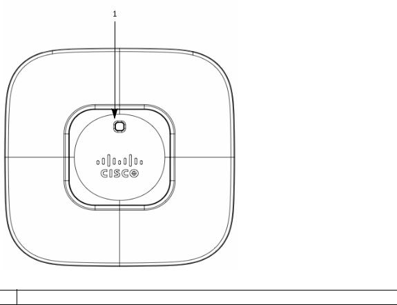
The 702I model access points have integrated antennas and do not have external connectors on the top of the unit; however, they do have the LED indicator on top of the unit, as shown in Figure 1.
Figure 1 Access Point LED Indicator (top)
1 LED indicator
6

Cisco Confidential -- Review Draft
The ports and connections on the side of the access point are shown in Figure 2.
Figure 2 Access Point Ports and Connections (bottom)
7

Cisco Confidential -- Review Draft
1 |
Reset button |
5 |
AC power connector |
|
|
|
|
2 |
USB port |
6 |
Mounting bracket pins (feet for desk or |
|
|
|
table-top mount) |
|
|
|
|
3 |
Gbit Ethernet port |
7 |
Security hasp |
|
|
|
|
4 |
Console port |
|
|
|
|
|
|
7 Configuring the Access Point
This section describes how to connect the access point to a wireless LAN controller. Because the configuration process takes place on the controller, see the Cisco Wireless LAN Controller Configuration Guide for additional information. This guide is available on Cisco.com.
The Controller Discovery Process
The access point uses standard Control and Provisioning of Wireless Access Points Protocol (CAPWAP) to communicate between the controller and other wireless access points on the network. CAPWAP is a standard, interoperable protocol which enables an access controller to manage a collection of wireless termination points. The discovery process using CAPWAP is identical to the Lightweight Access Point Protocol (LWAPP) used with previous Cisco Aironet access points. LWAPP-enabled access points are compatible with CAPWAP, and conversion to a CAPWAP controller is seamless. Deployments can combine CAPWAP and LWAPP software on the controllers.
The functionality provided by the controller does not change except for customers who have Layer 2 deployments, which CAPWAP does not support.
In a CAPWAP environment, a wireless access point discovers a controller by using CAPWAP discovery mechanisms and then sends it a CAPWAP join request. The controller sends the access point a CAPWAP join response allowing the access point to join the controller. When the access point joins the controller, the controller manages its configuration, firmware, control transactions, and data transactions.
Note For additional information about the discovery process and CAPWAP, see the Cisco Wireless LAN Controller Software Configuration Guide. This document is available on Cisco.com.
Note CAPWAP support is provided in controller software release 5.2 or later. However, your controller must be running release 7.x.x.x or later to support 700 series access points.
8

Cisco Confidential -- Review Draft
Note You cannot edit or query any access point using the controller CLI if the name of the access point contains a space.
Note Make sure that the controller is set to the current time. If the controller is set to a time that has already occurred, the access point might not join the controller because its certificate may not be valid for that time.
Access points must discovered a controller before they can become an active part of the network. The access point supports these controller discovery processes:
•Layer 3 CAPWAP discovery—The access point performs a local broadcast (255.255.255.255) discovery request to find any contollers on the same subnet/vlan. The request can be forwarded to other networks by the IP helper featuer that is present on switches and router.
•Locally stored controller IP address discovery—If the access point was previously joined to a controller, the IP addresses of the primary, secondary, and tertiary controllers are stored in the access point’s non-volatile memory. This process of storing controller IP addresses on an access point for later deployment is called priming the access point. For more information about priming, see the “Performing a Pre-Installation Configuration” section on page 10.
•DHCP server discovery—This feature uses DHCP option 43 to provide controller IP addresses to the access points. Cisco switches support a DHCP server option that is typically used for this capability. For more information about DHCP option 43, see the “Configuring DHCP Option 43 and DHCP Option 60” section on page 32.
•DNS discovery—The access point can discover controllers through your domain name server (DNS). For the access point to do so, you must configure your DNS to return controller IP addresses in response to CISCO-CAPWAP-CONTROLLER.localdomain, where localdomain is the access point domain name. Configuring the CISCO-CAPWAP-CONTROLLER provides backwards compatibility in an existing customer deployment. When an access point receives an IP address and DNS information from a DHCP server, it contacts the DNS to resolve CISCO-CAPWAP-CONTROLLER.localdomain. When the DNS sends a list of controller IP addresses, the access point sends discovery requests to the controllers.
Preparing the Access Point
Before you mount and deploy your access point, we recommend that you perform a site survey (or use the site planning tool) to determine the best location to install your access point.
You should have the following information about your wireless network available:
• Access point locations.
9

Cisco Confidential -- Review Draft
•Access point mounting options: below a suspended ceiling, on a flat horizontal surface, or on a desktop.
Note You can mount the access point above a suspended ceiling but you must purchase additional mounting hardware: See “Mounting the Access Point” section on page 13 for additional information.
•Access point power options: power supplied by the recommended external power supply (Cisco AIR-PWR-B), a DC power supply, PoE from a network device, or a PoE power injector/hub (usually located in a wiring closet).
Note Access points mounted in a building’s environmental airspace must be powered using PoE to comply with safety regulations.
Cisco recommends that you make a site map showing access point locations so that you can record the device MAC addresses from each location and return them to the person who is planning or managing your wireless network.
Installation Summary
Installing the access point involves these operations:
•Performing a pre-installation configuration (optional)
•Mounting the access point
•Grounding the access point
•Deploying the access point on the wireless network
Performing a Pre-Installation Configuration
The following procedures ensure that your access point installation and initial operation go as expected. A pre-installation configuration is also known as priming the access point. This procedure is optional.
Note Performing a pre-installation configuration is an optional procedure. If your network controller is properly configured, you can install your access point in its final location and connect it to the network from there. See the “Deploying the Access Point on the Wireless Network” section on page 13 for details.
10
Cisco Confidential -- Review Draft
Pre-Installation Configuration Setup
The pre-installation configuration setup is shown in Figure 3.
Figure 3 Pre-Installation Configuration Setup
Controller
Layer 3 devices
Cisco Aironet access points
272488
To perform pre-installation configuration, perform the following steps:
Step 1 Make sure that the Cisco wireless LAN controller DS port is connected to the network. Use the CLI, web-browser interface, or Cisco Prime Infrastructure procedures as described in the appropriate Cisco wireless LAN controller guide.
a.Make sure that access points have Layer 3 connectivity to the Cisco wireless LAN controller Management.
b.Configure the switch to which your access point is attach to. See the Cisco Unified Wireless Network WLAN Controller Guide: Cisco 5500 Series WLAN Controllers for additional information.
c.Set the Cisco wireless LAN controller as the master so that new access points always join with it.
11
 Loading...