


Christie S4, S6, S9, Vista S3, Vista S5 User Manual
...


 User's Manual
Table of Contents
1 Introduction
Section |
Contents |
Page |
1.1 |
The Projectors................................................................................................... |
1-1 |
1.2 |
Components ...................................................................................................... |
1-2 |
1.3 |
Purchase Record and Warranty Registration..................................................... |
1-2 |
2 |
Installation & |
2.1 |
Quick Setup....................................................................................................... |
2-1 |
Setup |
2.2 |
Installation Considerations................................................................................ |
2-3 |
|
|
|
2.3 |
Projector Position and Mounting .................................................................... |
2-10 |
|
|
2.4 |
Source Connections ........................................................................................ |
2-15 |
|
|
2.5 |
Power Connection........................................................................................... |
2-24 |
|
|
2.6 |
Operating Orientation ..................................................................................... |
2-24 |
|
|
2.7 |
Leveling .......................................................................................................... |
2-24 |
|
|
2.8 |
Zoom, Focus & Lens Offset ............................................................................ |
2-25 |
|
|
2.9 |
Serial Port Connections................................................................................... |
2-27 |
|
|
2.10 |
Keypad Protocols and Conversion.................................................................. |
2-34 |
3 Operation
3.1 |
Overview........................................................................................................... |
3-1 |
3.2 |
Projector Basics ................................................................................................ |
3-1 |
3.3 |
Using the Keypad.............................................................................................. |
3-4 |
3.4 |
Navigating the Menus ..................................................................................... |
3-14 |
3.5 |
Using Inputs and Channels.............................................................................. |
3-18 |
3.6 |
Adjusting the Image ........................................................................................ |
3-24 |
3.7 |
Configuring System Parameters...................................................................... |
3-41 |
3.8 |
Working With the Lamp ................................................................................. |
3-47 |
3.9 |
Projector Status............................................................................................... |
3-50 |
3.10 |
Using Multiple Projectors ............................................................................... |
3-51 |
3.11 |
Error Conditions ............................................................................................. |
3-54 |
4 Maintenance
4.1 |
Warnings and Guidelines .................................................................................. |
4-1 |
4.2 |
Cleaning............................................................................................................ |
4-3 |
4.3 |
Replacing Keypad Batteries.............................................................................. |
4-3 |
4.4 |
Replacing the Lamp and Filter .......................................................................... |
4-4 |
4.5 |
Replacing the Lens............................................................................................ |
4-9 |
4.6 |
Troubleshooting.............................................................................................. |
4-12 |
5
6
Specifications
Appendices
5.1 |
Specifications.................................................................................................... |
5-1 |
A |
Glossary ........................................................................................................... |
A-1 |
B |
Keypad Reference ........................................................................................... |
B-1 |
C |
Menu Tree........................................................................................................ |
C-1 |
D |
Serial Communication Cables.......................................................................... |
D-1 |
E |
Throw Distance................................................................................................ |
E-1 |
F |
Optional Input Modules ................................................................................... |
F-1 |
NOTE: Due to continuing research, all information in this manual is subject to change without notice
54-017115-13P Software Version 2.1 (10/02) |
Roadster/Vista User's Manual |
iii
|
Section 1 |
|
|
Introduction |
|
|
|
|
|
The Vista and Roadster projectors are professional quality DMD projectors that use |
|
|
||
1.1 The Projectors |
||
Digital Light Processing (DLP ) technology from Texas Instruments to achieve |
high-brightness multimedia and video projection. All models are compatible with standard international video formats and can interface with IBM -compatible PC, Macintosh computers and workstations. Vista models are ideal for mounting in
|
large audience venues in which there may be |
|
|
high levels of ambient light, such as in |
|
|
corporate boardrooms, auditoriums, and lecture |
|
|
halls. The Roadster offers this same high level |
|
|
of performance but with additional ruggedness |
|
|
enabling frequent transport, changing |
|
|
installations and easy stacking of multiple |
|
|
projectors. This robust projector is well-suited |
|
(Roadster model shown) |
for use in outdoor stages and arenas. Vista and |
|
Roadster features include: |
||
|
◊Native resolution of 1024 x 768 (X models) or 1280 x 1024 (S models), scaleable
◊Brightness (ANSI lumens, ±10%):
•Vista X3/S3 = 3000 • Roadster X4/S4 = 4000 (note: X4/S4 discontinued)
•Vista X5/S5 = 5000, Roadster X6/S6 = 6000 (note: Vista S5 discontinued)
•Roadster X9/S9 = 8500
◊Contrast Ratio
•Vista X3/X5, Roadster X4/X6 = 300:1 ANSI, 500:1 full on/off
•Roadster X9 = 400:1 ANSI, 500:1 full on/off
•Roadster S9 = 400:1 ANSI, 800:1 full on/off
•“S” models with 700W or 1200W lamp/power supply = 300:1 ANSI, 800:1 full on/off
◊Smooth and versatile remote control of lens, with Intelligent Lens System (ILS™) for recall of lens settings from source-to-source (standard in Roadster only)
◊Tandem horizontal and vertical sizing software control
◊Independent vertical stretch for changing aspect ratios
◊Keystone adjustment via menu option (“X” models only)
◊Interchangeable lenses for diagonal screen sizes up to 40 or more feet
◊Display of NTSC, PAL and SECAM video input
◊Display from PCs, VCRs, laser disc players, video cameras, etc.
◊Intuitive on-screen menus or hidden direct control with built-in or remote keypad
◊Memory for up to 99 custom “channels” (source setups) accessible with keypress
◊Controller and switcher compatibility
◊Built-in RS-232 and RS-422 ports for computer control and networked projectors
◊Remote-controlled shutter (optional in Vista models)
◊Rugged functional design for harsh environments and secure handling (Roadster)
◊Simple hardware option for hoisting and for stacking multiple projectors (Roadster)
◊Modular design for easy servicing. Exterior panels of metal and polymer.
Roadster/Vista User’s Manual |
1-1 |
INTRODUCTION |
|
|
|
|
||
|
|
|
|
|||
How The Projectors Work |
' Vista and Roadster accept data/graphics and video input signals for projection on to |
|||||
|
|
|
|
|
front or rear flat screens. High brightness light is generated by an internal Xenon arc |
|
|
|
|
|
|
lamp, then modulated by three DMD (digital micromirror device) panels that provide |
|
|
|
|
|
|
digitized red, green or blue color information. Light from the “on” pixels of each |
|
|
|
|
|
|
panel is reflected, converged and then projected to the screen through a single front |
|
|
|
|
|
|
lens, where all pixels are perfectly superimposed as a sharp full-color image. |
|
|
|
|
|
|
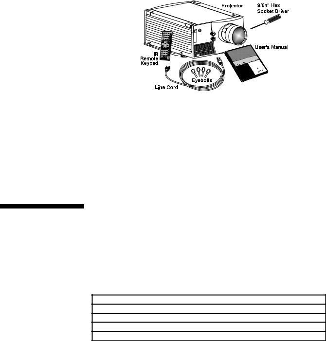
Included with Vista and Roadster is an infrared (IR) remote keypad, a power cord, a |
|
|
|
|
|
|
||
1.2 |
Components |
|
||||
|
9/64” hex socket ball driver, eyebolts (Roadster only) and a Roadster/Vista User’s |
|||||
Manual. Make sure that you received everything.
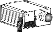
Figure 1.1. Components (SHOWN: Roadster WITH ADDED LENS)
Differences Between Roadster and Vista Models
|
|
|
Motorized Lens |
|
Shutter |
|
Audio |
|
Handles & Slot Covers |
|
Stacking Slots |
|
Eyebolts |
|
|
Roadster |
|
U |
|
U |
|
discontinued |
|
U |
|
U |
|
U |
|
|
Vista |
|
optional |
|
optional |
|
U |
|
not available |
|
not available |
|
optional |
|
|
|
|
|
U = Standard |
|
|
|
|
|
|
|
|
|
|
1.3Purchase Record and Warranty Registration
MODELS and AVAILABILITY: The Roadster line and the Vista line both offer models differing in light output and/or image resolution. All combinations are documented in this manual, however the following models are no longer manufactured:
Roadster X4 / S4 |
Vista S5 |
Whether the projector is under warranty or the warranty has expired, Christie’s highly trained and extensive factory and dealer service network is always available to quickly diagnose and correct projector malfunctions. Complete service manuals and updates are available to service technicians for all projectors.
Should you encounter a problem with the projector and require assistance, contact your dealer or Christie. In many cases, any necessary servicing can be performed on site. If you have purchased the projector, fill out the Purchase Record below and keep with your records. In addition, make sure to complete the Warranty Registration at the Christie website—this will ensure that you receive all future product communications promptly.
Purchase Record
Dealer:
Dealer Phone Number:
Projector Serial Number*:
Purchase Date:
Installation Date, if applicable:
* NOTE: The projector serial number is located on the projector's rear identification label
1-2 Roadster/Vista User’s Manual
Section 2
Installation & Setup
This section explains how to install and set up the projector. If you are familiar with the projector and want to quickly set it up for temporary use, follow the Quick Setup instructions below. For a more complete setup, follow the instructions and guides covered in the remaining subsections. This section assumes that the video decoder is installed.
NOTE: The lens is not installed for shipping. For instructions on how to install or replace a lens, refer to 4.5, Replacing the Lens.
Follow these steps for quick setup of the projector in a standard floor mount position.
2.1 Quick Setup
STEP 1 ' Position the Projector
Set the projector at the expected throw distance (projector-to-screen distance) and vertical position. See 2.3, Projector Position and Mounting and Appendix E. Make sure that the projector is level from side-to-side (see 2.7, Leveling).
STEP 2 ' Connect a Source
Locate the main input panel at the rear of the projector. The lower left area, labeled INPUT 1, accepts an RGB input via BNC connectors. The upper right area (assuming a video decoder is installed) accepts a composite video atINPUT 3 or S-video input at INPUT 4. Connect your source to the appropriate panel connectors.
STEP 3 ' Connect the Line Cord to AC Power
Connect the projector’s line cord to the AC receptacle at the lower right rear corner of the projector and to proper AC. Use the line cord provided with the projector (seeSection 5).
Model |
AC Power Required |
X/S3 and X/S4 |
100-240 VAC, 50-60 Hz, max. 11.5 amps @ 100V |
X/S5 and X/S6 |
200-240 VAC, 50-60 Hz, max. 8.5 amps @ 200V |
X9/S9 |
200-240 VAC, 50-60 Hz, max. 12 amps @ 200V |
WARNING
Do not attempt operation if the AC supply and cord are not within the specified voltage and power range. See Section 5.
STEP 4 ' Turn the Projector ON
Using either the built-in or remote keypad, press Power* and hold for approximately 1 second to turn the projector on (or press Power*
 ON ). Let the projector warm up for about five minutes. The POWER LED, located in the lower right corner of the rear input panel, should glow a steady green.
Roadster/Vista User’s Manual |
2-1 |

INSTALLATION AND SETUP
STEP 5 ' Select a Source
Using either the built-in or remote keypad, press Input1 , Input2
 , Input3
 , or Input4
 to select and display the image for the source you connected in Step 2. The display will resize as needed, producing an image as large as possible for the type of source present.
STEP 6 ' Adjust Image (NON-MOTORIZED MODELS)
• ZOOM: With the input image displayed, rotate the textured ring on the lens barrel to increase or decrease the image size (this requires a zoom lens). If you don’t have a zoom lens or you can’t adjust the image enough, the projector may not be positioned at the proper throw distance for your screen size. Power down, unplug the projector and move it towards or away from the screen. See 2.3, Projector Position and Mounting for details.
• FOCUS: At the lens opening, turn the focus tab to focus the image clearly.
• OFFSETS: Turn either or both of the knobs adjacent to the lens if you need to align the image with your screen—turn the top knob to raise or lower the image, turn the bottom knob to shift the image left or right. Re-check focus.
• OTHER: Press Menu to refine other display parameters as described in Section 3.
Adjust Image (MOTORIZED MODELS)
NOTE: Motorized lens controls are standard on Roadster models only.
With the input image displayed, press Lens on any keypad.
Figure 2.1. Motorized Lens Adjustments
2-2 Roadster/Vista User’s Manual

 INSTALLATION AND SETUP
2.2Installation Considerations
If you’ve just installed the lens, select “Calibrate Lens” before making any adjustments (see Section 3 for details). Then, with the Lens Control menu displayed, use the keypad as shown in Figure 2.1 to focus the image clearly and, if a zoom lens is present, to increase or decrease image size. If desired, adjust horizontal and/or vertical offsets to shift the lens and image location—ranges are shown in 2.3, Projector Position and Mounting.
Press Menu to refine other display parameters, if necessary. See 3.5, Using Inputs and Channels if you want to work with other source inputs or defined channels.
You may want to reduce initial setup time by starting with an “Auto Setup”. The projector will automatically optimize a variety of display settings according to the incoming source detected. You can then re-adjust these settings at any time, if desired.
Although this projector delivers a high brightness quality output, final display quality could be compromised if the projector is not properly installed. This subsection discusses issues you should consider before proceeding with a final installation. Even if you do not intend to use the projectors in a fixed and permanent installation, this subsection will help you to better understand what you can do to enhance display performance.
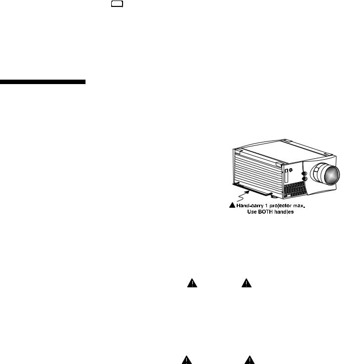
Lifting, Hoisting |
' For any new installation, you will likely |
|
and Stacking |
have to safely lift or hoist the projector into |
|
|
place. Keep in mind the following |
|
|
guidelines for safety. |
|
|
Lifting |
|
|
The Roadster model includes a set of side |
|
|
handles for convenient brief hand transport, |
|
|
such as when a single projector is lifted or |
|
|
carried over short distances by 2 people, or |
|
|
for the addition of safety straps when hoisting (see Hoisting, below). Note that these |
|
|
handles are not intended to support the entire weight of the projector for extended |
|
|
periods of time, nor can a set of handles support the weight of more than a single |
|
|
projector. In particular, never hoist or suspend the projector from these handles alone. |
|
|
Vista models do not have handles. |
|
|
WARNING |
|
|
Do not use the side handles to suspend the projector. |
|
|
Hoisting |
|
|
Safely hoisting the projector into place requires hoisting hardware available in a |
|
|
Christie Hoisting/Stacking Kit specially designed for the projector, as well as |
|
|
appropriate nylon webbed safety straps and rigging equipment. Never hoist a |
|
|
projector by its feet, handles or any other component (Figure 2.3). |
|
|
IMPORTANT |
|
|
It is recommended that you remove |
|
|
the lens before hoisting a projector. |
|
|
Roadster/Vista User’s Manual |
2-3 |

INSTALLATION AND SETUP
TO HOIST INVERTED
Roadsters: For one projector,
remove the feet, insert 4 eyebolts provided and attach a hoisting/rigging frame that will enable cables to remain
vertical at all times. Add
safety strapping at the side handles before hoisting into
place. Never hoist or suspend
a projector if there is any slack in cabling or straps, and keep all cables in place for a “flown” installation. NOTE:
Use straps and cabling with load capacity adequate for the projector weight. See
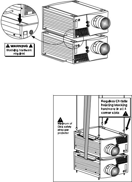
Section 5. For a stack of two projectors, remove the small chrome cover near each corner of the lid, and install the threaded rods and heavy-duty eyebolt couplings provided in the Christie Hoisting/Stacking Kit. NOTE: Follow all instructions provided with the kit. Use a minimum of one safety strap per projector–i.e., if you are hoisting a stack of 2 projectors, both projectors must have their own safety strap attached. See Figure 2.5.
Figure 2.3. Do not hoist by handles or feet. Do not angle cables or straps.
TO HOIST NON-INVERTED Roadsters: You must use the hoisting hardware available in a Christie Hoisting/Stacking Kit specially designed for the projector–follow the instructions provide with the kit. Hoist with cabling and straps as described for inverted Roadsters, above.
TO HOIST AN INVERTED or NON-INVERTED Vista: Securely wrap hoisting cabling and
safety straps around the whole projector. Attach to the proper Christie ceiling mount only–never suspend or “fly” this model.
NOTE: Vista models cannot use the Christie Hoisting/Stacking Kit for hoisting into place.
Stacking
See Figure 2.4. A maximum of 2 Roadster projectors can be safely secured together with the Christie Hoisting/Stacking Kit hardware–follow all instructions provided in the kit. For safety, one projector should never “rest” on another without the proper
2-4 Roadster/Vista User’s Manual
 INSTALLATION AND SETUP
stacking hardware (available separately) in place, firmly securing the projectors together. If you are hoisting a stack, secure a safety strap to at least one handle of each projector–keep the strap taut.
NOTE: Vista models cannot be stacked.
 WARNING
Do not stack projectors without using Christie Hoisting/Stacking hardware. The top projector could slide off and cause injury or death.
 WARNING
Do not carry a stack.
Figure 2.4. Stacking (Roadster only). Requires optional hardware.
 WARNING
Do not invert only one projector within a stack.
TO HOIST STACKED Roadsters: Secure
the projectors together with Christie Hoisting/Stacking Kit hardware, following the instructions provided in the kit. Hoist with cabling and straps as described in Hoisting, above–make sure to use at least one safety strap on each projector in the stack. See Figure 2.5.
 WARNING
Use Christie Hoisting/Stacking hardware only.
Figure 2.5. Hoisting a Stack, Minimum
Configuration (SHOWN INVERTED)
Roadster/Vista User’s Manual |
2-5 |

INSTALLATION AND SETUP
Installation Type ' Choose the installation type which suits your needs: front or rear screen, floor mount or inverted mount.
Front Screen, Floor Mount Installation
|
ADVANTAGES |
CONSIDERATIONS |
|
|
|
• Easy to set up |
• Shares floor space with audience |
|
• |
Can be moved or changed quickly |
|
• |
Easy to access |
|
Front Screen, Inverted Mount (ceiling) Installation
|
ADVANTAGES |
|
CONSIDERATIONS |
|
|
|
|
• |
Does not take up audience space |
• |
Installation is more permanent |
• |
Projector is unobtrusive |
• |
It is more difficult to access the projector |
• |
Projector cannot be accidentally moved |
|
|
Rear Screen, Floor Mount Installation
|
ADVANTAGES |
|
CONSIDERATIONS |
|
|
|
|
• |
Projector is completely hidden |
• |
Requires separate room |
• |
Projector is easily accessed |
|
|
• |
Usually good ambient light rejection |
|
|
Rear Screen, Inverted Mount (ceiling) Installation
|
ADVANTAGES |
|
CONSIDERATIONS |
|
|
|
|
• |
Projector is completely hidden |
• |
Requires separate room |
• |
Usually good ambient light rejection |
• |
Installation cost is usually higher |
Rear Screen, Floor Mount with Mirror
|
ADVANTAGES |
|
CONSIDERATIONS |
|
|
|
|
• |
Projector is completely hidden |
• |
Requires separate room |
• |
Usually good ambient light rejection |
• |
Installation cost is usually higher |
• |
Requires less space behind screen than |
|
|
|
other rear screen installations |
|
|
Screen Type ' Front Screen Installations
While there are two basic screen types, flat and curved, generally flat screens are recommended for this projector. Flat screens offer a gain of about 1 with a viewing angle just less than 180°. Incident light reflects equally in all directions so the audience can see the display from various angles. Because of the low gain, flat screens are most effective when ambient lighting is reduced, although this difference may be negligible given the high brightness output from this projector.
Figure 2.6. Audience Coverage with Flat Screen
2-6 Roadster/Vista User’s Manual
 INSTALLATION AND SETUP
|
NOTE: Lenses for this projector are designed primarily for use with flat screens, but |
|
the projector depth-of-field range allows the lens to be focused on curved screens as |
|
well. While focus remains sharp in the corners, there may be significant pincushion |
|
distortion, primarily at the top of the screen. |
|
Rear Screen Installations |
|
There are two basic types of rear screens: diffused and optical. A diffused screen has |
|
a surface which spreads the light striking it. Purely diffused screens have a gain of |
|
less than 1. The main advantage of the diffused screen is its wide viewing angle, |
|
similar to that of a flat screen for front screen projection. Optical screens take light |
|
from the projector and redirect it to increase the light intensity at the front of the |
|
screen. This reduces it in other areas. A viewing cone, similar to that of a curved |
|
front screen installation, is created. |
|
To summarize, optical screens are better suited for brightly lit rooms where the |
|
audience is situated within the viewing cone. Diffused screens may be better suited |
|
when a wide viewing angle is required but there is low ambient room lighting. |
Screen Size |
' Screen size may be from 5 to 40 feet diagonal, depending on the lens you are using. |
|
For instance, a 1.2:1 lens can produce a 5 to 25 foot image size, whereas a 4-7:1 |
|
zoom lens produces an 8 to 40 foot image size. Choose a screen size which is |
|
appropriate for your lens and application. Keep in mind that if the projector will be |
|
used to display text information, the image size must allow the audience to recognize |
|
all text clearly. The eye usually sees a letter clearly if eye-to-text distance is less than |
|
150 times the height of the letter. Small text located too far from the eye may be |
|
illegible at a distance no matter how sharply and clearly it is displayed. |
|
To fill a screen with an image, the aspect ratio of the screen should be equal to the |
|
aspect ratio of the image. The aspect ratio of an image is expressed as the ratio of its |
|
width to its height. Standard video from a VCR has a 4:3 aspect ratio. For example, |
|
to display a VCR output with a 4:3 aspect ratio onto a 10 foot (3m) high screen, the |
|
width of the screen must be at least 13.3 feet (4m). |
Screen Aspect Ratio |
' Aspect ratio describes the proportion of the screen and is expressed as the ratio of |
|
width to height, such as “4:3” or “5:4” (see right). Although image size and image |
|
aspect ratio can both be adjusted quickly through projector software, it is still a good |
|
idea to choose a screen aspect ratio which is most appropriate for your intended |
|
applications. Ideally, to exactly fill a screen with an image, the aspect ratio of the |
|
screen should correspond to the aspect ratio of the image, which depends on the |
|
source in use. For example, standard video from a VCR has a 4:3 ratio |
|
(approximately), whereas a high resolution graphics signal typically has a 5:4 aspect |
|
ratio. By default, images from your projector will be as large as possible and, with |
|
the exception of graphics sources, will maintain their aspect ratio. |
|
NOTE: With a few exceptions, sources with less than 1280 x 1024 resolution have a |
|
4:3 aspect ratio. The normal aspect ratio for 1280 x 1024 sources is 5:4. |
Roadster/Vista User’s Manual |
2-7 |
INSTALLATION AND SETUP
Using a 5:4 Screen with “S” Models
With one exception, XGA images will— by default—resize to fill an SXGA screen with “S” models. The exception (illustrated in Figure 2.7) is that video signals will retain their aspect ratio—fill the screen by increasing Vertical Stretch to slightly expand the image to the top and bottom edges of the screen. For details, see 3.6, Adjusting the Image.
Using a 4:3 Screen with “S” Models
Figure 2.7. Adjusting a 4:3 Video
Image
If you are using a 4:3 screen with “S” models (which produce 5:4 images), images will—by default—slightly overlap the screen vertically. To remedy, reduce Vertical Stretch so that the “too tall” 5:4 image no longer spills over the top or bottom of the screen (Figure 2.8). This control eliminates the need for simply moving the projector farther from the screen, which would result in black borders for all sources. See 3.6, Adjusting the Image.
NOTE: The Vertical Stretch adjustment may soften the image slightly, but is not noticeable in most cases.
Figure 2.8. Using a 4:3 Screen for a mix of 5:4 and 4:3 sources (“S” models)
Ideal Room Lighting ' The high brightness output of this projector is certainly well suited for locations where ambient lighting is less than optimum for projection, yet there are still many simple things you can do to optimize your installation.
Visiting a movie theater can give you an idea of what makes an ideal projection environment. Walls, floors and furnishings are dark and matte finished. A projection room should not have white reflective ceilings or non-directional lighting such as fluorescent lights. The white ceiling spreads light, making the room appear brighter. Keep lighting and reflections to a minimum.
If it is not possible to eliminate fluorescent lights, consider using incandescent spot lighting or parabolic reflectors ("egg crates") to direct light down to the floor. Light dimmers or rheostats allow further control.
Outside windows are undesirable in any projection room. A small crack between curtains on a sunny day can wash out a projected image. If you do have windows, make sure that window coverings are opaque and overlapping — some window coverings are designed to provide up to 100 percent blockage of outside light. Ideally, the material should have a matte finish.
2-8 Roadster/Vista User’s Manual

 INSTALLATION AND SETUP
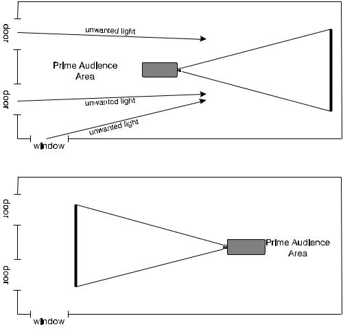
To minimize the effects caused by unwanted light from door and aisle ways, carefully choose the position of your projector and screen. Figure 2.9 shows an installation where poor screen placement allows too much unwanted light to enter the screen. In Figure 2.10, screen and the projector are positioned so that unwanted light is minimized.
Figure 2.9. Poor Screen Placement
Figure 2.10. Better Screen Placement
Even with all lighting removed it is still possible that room reflections within the room can slightly degrade the image. Light from the projection screen should be absorbed by the ceilings, walls and floors so that it will not be reflected back to the screen. Again, keep reflective surfaces to a minimum.
Other Considerations ' Here are some other considerations and tips which can help you improve your installation:
•Ventilation is an important factor when preparing a projection room. The ambient temperature should be kept constant and below 35°C (95°F). Keep the projector away from heating and/or air conditioning vents. Changes in temperature can cause drifts in the projector circuitry which may affect performance.
•Keep the projector away from devices which radiate electromagnetic energy such as motors and transformers. Common sources of these are slide projectors, speakers, power amplifiers, elevators, etc.
Roadster/Vista User’s Manual |
2-9 |
INSTALLATION AND SETUP
•For rear screen applications, less space is required if a mirror is used to fold the optical path.
•Choose the right screen size for the application:
◊As screen size increases, magnification increases and reduces brightness. Select a screen size which is appropriate for the venue, but not larger than that required.
◊Installing a large screen in a small room is similar to watching television close up; too large a screen can overpower a room. A good rule of thumb is to be no closer than 1.5 times the width of the screen.
◊Larger screens require greater attention to lighting conditions.
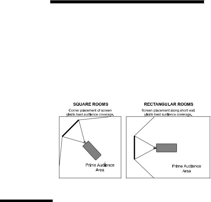
•When laying out the projection room, consider positioning the projector and screen in a manner which will achieve maximum audience coverage and space efficiency. For example, placing the screen along the larger wall in a rectangular room will reduce audience coverage. Figure 2.11 shows two examples of how audience coverage is maximized.
Figure 2.11. Screen Locations for Maximum Audience Coverage
2.3Projector Position and Mounting
Installation type, screen type, and lighting all affect where the projector is positioned. In addition, both throw distance (the distance between the projector and screen) and vertical position (the height of the projector in relation to the screen) must be determined for every new installation. Both depend on the screen size and lens type you are using. Make sure that the room can accommodate the required position of the projector for the chosen screen size.
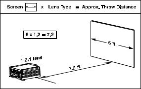
Throw Distance ' Throw distance is the distance between the projector's front feet and the screen. For any installation, an accurate throw distance must be determined in order for the image to be of the right size for your screen–the farther the projector is from the screen, the larger the image.
NOTE: If your projector is tilted in relation to the screen, as is sometimes the case for large venues or elevated installations, throw distance still represents the smallest measurement between the screen and front feet.
2-10 Roadster/Vista User’s Manual
 INSTALLATION AND SETUP
Throw distance is roughly equal to the horizontal width of the screen multiplied by the type of lens you are using. For example, if you are using a 0.8:1 lens, proper throw distance will be approximately 0.8 x the screen width. Once you know your screen size and lens, you can estimate throw distance needed (see example in Figure 2.12).
|
IMPORTANT: For proper |
|
Figure 2.12. Estimating Throw Distance |
|||
|
|
|
(SEE APPENDIX E) |
|||
|
placement in an installation, |
|
|
|
|
|
|
always refer to the throw distance formula and/or graph for your lens as listed in |
|||||
|
Appendix E. Keep in mind that due to lens manufacturing tolerances for lens focal |
|||||
|
length, actual throw distance can vary ±5% between lenses described as having the |
|||||
|
same throw ratio. |
|
|
|
|
|
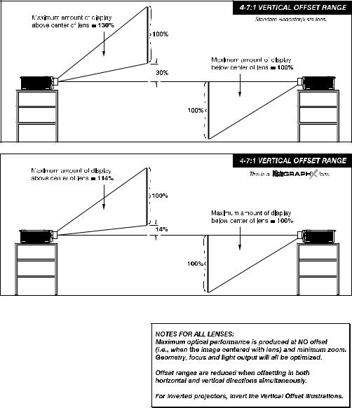
Vertical & Horizontal |
' THE VERTICAL POSITION of the projector in relation to the screen also depends on the |
|||||
Position |
size of the screen and the lens type. Correct vertical position helps ensure that the |
|||||
|
image will be rectangular in shape rather than keystoned (having non-parallel sides) |
|||||
|
and that image focus and brightness both remain optimized. |
|||||
|
In addition, vertical position of the image can be offset—that is, moved up or done— |
|||||
|
either by turning the top knob on the front of the projector (the one nearest to the IR |
|||||
|
sensor) in non-motorized projectors, or through software in motorized projectors. |
|||||
|
Offsets range up to 130%, depending on the specific lens, whether it is motorized or |
|||||
|
not, what amount of zoom is in effect and whether or not you are also offsetting |
|||||
|
horizontally. |
|
|
|
|
|
|
See Table 2.1 for the maximum percentage of the image that can be displayed above |
|||||
|
or below the center of each type of motorized lens. These image offsets are also |
|||||
|
illustrated in Figure 2.13. |
|
|
|
|
|
|
NOTE: Shown are approximate motorized offset ranges—manual offsets may differ. |
|||||
|
Table 2.1. Maximum % of Image Offset from Lens Center |
|||||
|
|
|
|
|
|
|
|
|
Lens Type |
|
Max. Recommended Image Offset |
|
|
|
|
|
|
|
|
|
|
|
0.8:1 |
|
×91% |
Ø100% |
|
|
|
1.2:1 |
|
×104% |
Ø100% |
|
|
|
1.5 - 2.2:1 |
|
×128% |
Ø100% |
|
|
|
2.2 - 4:1 |
|
×128% |
Ø100% |
|
|
|
2.5 – 4:1 |
|
×123% |
Ø100% |
|
|
|
4-7:1 |
|
×130% |
Ø100% |
|
|
|
4-7:1 |
|
×114% |
Ø100% |
|
|
|
NOTE: VistaGRAPHX lens. Threaded lens adapter required. |
||||
Motorized ZOOM feature is not available for VistaGRAPHX lenses.
The 0.8:1 lens is not recommended for use in “S” models.
Roadster/Vista User’s Manual 2-11

INSTALLATION AND SETUP
Figure 2.13. Maximum Vertical Offsets
Continued…
2-12 Roadster/Vista User’s Manual

 INSTALLATION AND SETUP
Figure 2.13. Maximum Vertical Offsets, Continued (ALL LENSES)
NOTES: 1) If you cannot raise or
lower the image enough using mechanical vertical offsets, try adjusting V-Position in the Size
and Position menu (see 3.6, Adjusting the Image). 2) If the
image becomes keystoned or exhibits uneven brightness, the
projector may simply be too high
or low in relation to the screen. 3) Recommended offset ranges can be exceeded, however this may affect image quality. 4) Simultaneous horizontal and vertical offset limits the adjustment range of each.
THE HORIZONTAL POSITION of the image can be offset—that is, shifted left or right of lens center—either by turning the bottom knob on the front of the projector (the knob farthest from the IR sensor) in non-motorized projectors or through software in motorized projectors. The maximum horizontal offset for lenses that can be installed in this projector is shown in Figure 2.14. This value expresses the maximum percentage of the image that can be projected to one side of the lens center (roughly 77%, depending on the lens).
Roadster/Vista User’s Manual 2-13

INSTALLATION AND SETUP
Figure 2.14. Maximum Horizontal Offsets (ALL LENSES)
Mounting ' For typical front or rear floor mounts, mount the projector on a secure table or cart. Take care with a mobile cart—avoid sudden stops, excessive force and uneven surfaces that may cause the projector and cart combination to overturn.
The table or cart should be reasonably level. Fine adjustments to the projector level can be made by adjusting the height of the projector legs; refer to 2.7, Leveling for details.
Special Mounting
Note that projector can be rotated and mounted at any vertical angle—i.e., you can tilt the face of the projector up or down as much as desired for your installation. The side-to-side tilt, however, must not exceed 15° (see Figure 2.15). This limit ensures that the arc lamp in the projector operates properly and safely. Always make sure that exhaust air from the projector does not vent towards the lens, otherwise you may detect heat waves in your projected image.
Figure 2.15. Horizontal and Vertical Tilt Ranges
You must use the proper ceiling mount fixture or stacking kit for your projector. For more information, contact your dealer.
2-14 Roadster/Vista User’s Manual
INSTALLATION AND SETUP
Folded Optics ' In rear screen applications where space behind the projector is limited, a mirror may be used to fold the optical path. See right. The position of the projector and mirror must be accurately set—if considering this type of installation, call your dealer for assistance.
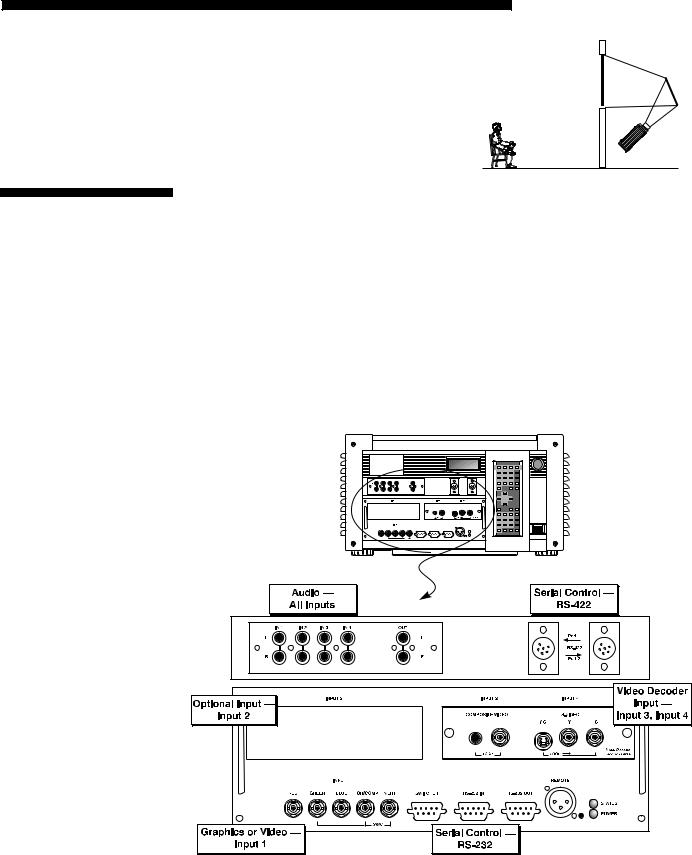
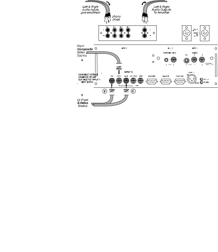
2.4Source Connections
The rear panel of the projector provides standard input panels to which you may connect a variety of sources. See Figure 2.16–the lower left area (INPUT 1) typically accepts an RGB signal from an external RGB source, or it can also be used for YPbPr signals or additional video sources. The upper right panel–the Video Decoder Module–accepts only composite video at INPUT 3 or S-video at INPUT 4 from devices such as VCRs, laser disk players or DVD players. There are also several optional interfaces available for connecting other sources at INPUT 2. Such an option installs in the upper left area, just below the audio connectors (if present). For any input, including the optional inputs, audio with loop through connects at the audio input panel located between the license label area and INPUT 2 (audio is standard on Vista only).
NOTES: 1) Audio connectors are standard on Vista models only. 2) For all connections to the projector, use only high-quality shielded cables.
Figure 2.16. Rear Connector Panel
Roadster/Vista User’s Manual 2-15

INSTALLATION AND SETUP
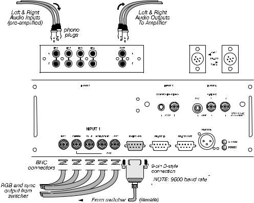
RGB Signals ' INPUT 1 provides 5 BNCs (connectors) for linking to a variety of sources, typically to an RGB source such as VGA, SVGA, XGA, Mac, PowerMac, DEC, Sun, SGI and others. This projector supports multiple sync types with RGB signals: sync-on-green, composite sync, and separate H & V syncs.
NOTE: Depending on the source, you may need a custom adapter cable with BNC connectors at the projector end and a different type of connector at the other (such as a 15-pin "D" connector for computer sources). Contact your dealer.
Connect the SYNC BNC input(s) first. Then connect the red, green and blue source outputs to the RED, GREEN, and BLUE BNCs on the INPUT 1 panel. If the source uses sync-on-green, only the red, green, and blue connections are required. If the source provides a composite sync output, connect it to the SYNC input labeled HOR/COMP. If the source provides separate horizontal and vertical sync outputs, connect horizontal sync to the SYNC input labeled HOR/COMP and connect vertical sync to SYNC input labeled VERT. See Figure 2.17.
NOTES: 1) If for some reason the projector fails to recognize as an RGB signal, specify this Color Space option within the Image Settings menu. See 3.6, Adjusting the Image. 2) To connect YPbPr signals–such as from DVD or analog HDTV sources–to INPUT 1, use the red, green and blue BNCs as described in YPbPr Signals later in this section.
Figure 2.17. Connecting RGB Input
AUDIO for INPUT 1 (STANDARD ON VISTA ONLY): To control audio levels in an audio/visual system, connect pre-amplified (line level) audio inputs to the “IN 1” left and right channel audio inputs located near the top left corner of the rear input panel. Then connect external audio amplification equipment to audio “OUT” for sound output. Audio connection cables require standard RCA type phono plugs.
2-16 Roadster/Vista User’s Manual
 INSTALLATION AND SETUP
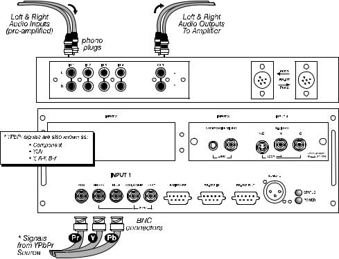
YPbPr Signal ' Connect a YPbPr signal (component video) to INPUT 1 as shown in Figure 2.18.
(COMPONENT VIDEO)
Figure 2.18. Connecting YPbPr Signal
NOTES: 1) If, for some reason, the projector fails to recognize a YPbPr signal, specify this Color Space option within the Image Settings menu. See 3.6, Adjusting the Image. 2) Do not connect digital component signals (known as YCbCr) to INPUT 1. Use the appropriate digital interface installed at INPUT 2.
AUDIO for INPUT 1 (STANDARD ON VISTA ONLY): To control audio levels in an audio/visual system, connect pre-amplified (line level) audio inputs to the “IN 1” left and right channel audio inputs located near the top left corner of the rear input panel. Then connect external audio amplification equipment to audio “OUT” for sound output. Audio connection cables require standard RCA type phono plugs.
Roadster/Vista User’s Manual 2-17
INSTALLATION AND SETUP
Composite Video ' The video decoder input panel provides simultaneous connection of both a composite video source (INPUT 3) and an S-Video source (INPUT 4).
If connecting a composite video source, use the Composite BNC connector or the
RCA phono jack at INPUT 3–do not use both as inputs. See Figure 2.19.
AUDIO for INPUT 1 (STANDARD ON VISTA ONLY): To control audio levels in an audio/visual system, connect pre-amplified (line level) audio inputs to the “IN 3” left and right channel audio inputs located near the top left corner of the rear input panel. Then connect external audio amplification equipment to audio “OUT” for sound output. Audio connection cables require standard RCA type phono plugs.
NOTE: If you want to loop a composite signal through to another projector or display device, see Video Loop Through later in this section.
Figure 2.19. Connecting Composite Video
2-18 Roadster/Vista User’s Manual

 INSTALLATION AND SETUP
S-Video ' The video decoder input panel provides simultaneous connection of both a composite video source (INPUT 3) and an S-Video source (INPUT 4).
If connecting an S-Video source, use the 4-pin mini DIN connector or the Y and C BNC connectors (luma and chroma) at INPUT 4–do not use both as inputs. See Figure 2.20.
Figure 2.20. Connecting S-Video
AUDIO for INPUT 1 (STANDARD ON VISTA ONLY): To control audio levels in an audio/visual system, connect pre-amplified (line level) audio inputs to the “IN 4” left and right channel audio inputs located near the top left corner of the rear input panel. Then connect external audio amplification equipment to audio “OUT” for sound output. Audio connection cables require standard RCA type phono plugs.
NOTE: If you want to loop an S-video signal through to another projector or display device, see Video Loop Through below.
Roadster/Vista User’s Manual 2-19
INSTALLATION AND SETUP
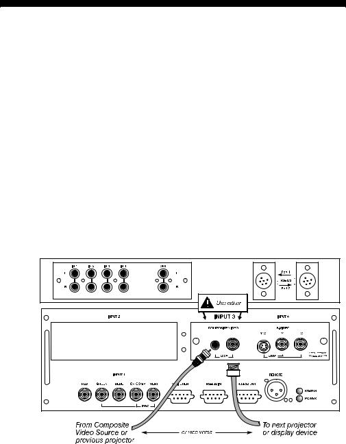
Video Loop Through ' To loop a single incoming video signal input (connected at the video decoder) through to another projector or display device, use the empty connector(s) adjacent to this same input as described below.
Composite Video Loop Through
CONNECTIONS: See Figure 2.21. From your source, connect a composite video signal to INPUT 3 using either the small phono plug or the adjacent BNC. Connect a second cable from whichever INPUT 3 connector is free to one of the composite video inputs of the next display device or projector. Continue this looping method for each projector, using either the phono plug or the adjacent BNC as input into INPUT 3, then using the other connector as an output (i.e., loop through). Whether you use the BNC or the phono plug as input or output depends on the type of cable you have on hand and what type of connectors are on each end. If desired, connect one audio signal to any projector as usual (audio is standard on Vista models only).
VIDEO TERMINATION: In Image Settings / Video Options control, make sure “Video Termination” is checked for the final projector only. All other projectors must have this option unchecked in order for the signal to continue. For other types of display devices in the chain, typically a “Hi-Z” switch position is needed.
Figure 2.21. Connections for Composite Video Loop Through
2-20 Roadster/Vista User’s Manual

INSTALLATION AND SETUP
S-Video Loop Through
CONNECTIONS: See Figure 2.22. From your source, connect an S-video source signal to INPUT 4 using either the 4-pin mini DIN or the 2 adjacent BNCs labeled Y and C. Connect a second cable from whichever INPUT 4 connector is free to one of the S- video inputs of the next display device or projector. Continue this looping method for each projector, using either 4-pin mini DIN or the 2 adjacent BNCs as input into INPUT 4, then using the other connector(s) as an output (i.e., loop through). Whether you use 4-pin mini DIN or the 2 adjacent BNCs as input or output depends on the type of cable you have on hand and what type of connectors are on each end. If desired, connect one audio signal to any projector as usual (audio is standard on Vista models only).
VIDEO TERMINATION: In the Image Settings / Video Options control, make sure “Video Termination” is checked for only the final projector. All other projectors must have this option unchecked in order for the signal to continue. For other types of display devices in the chain, typically a “Hi-Z” switch position is needed.
Figure 2.22. Connections for S-Video Loop Through
Roadster/Vista User’s Manual 2-21
INSTALLATION AND SETUP |
|
|
|
|
|
|
|
|
|
|
|
|
|
|
|
|
|
|
|
|
|
|
|
|
|
|
|
|
|
|
|
|
|
|
|
|
|
|
|
|
|
|
|
|
|
|
|
|
|
|
|
|
|
|
|
|
|
|
|
|
|
|
|
|
|
|
|
|
|
|
|
|
|
|
|
|
|
|
|
|
|
|
|
|
|
|
|
|
|
|
|
|
|
|
|
|
|
|
|
|
|
|
|
|
|
|
|
|
|
|
|
|
|
|
|
|
|
|
|
Extra Video |
' If you want to use an extra video source in addition to the video source(s) connected at |
||||||||||||||||||||||||||||||||||||||||||||||||||||||||||
– COMPOSITE OR S-VIDEO |
|
INPUT 3 or INPUT 4 connect either a Composite or S-Video source to INPUT 1 as shown in |
|||||||||||||||||||||||||||||||||||||||||||||||||||||||||
|
|
Figure 2.23. Do not connect both types here simultaneously. NOTE: For additional video |
|||||||||||||||||||||||||||||||||||||||||||||||||||||||||
|
|
inputs, install an optional Composite/S-Video Input Module at INPUT 2. |
|||||||||||||||||||||||||||||||||||||||||||||||||||||||||
|
|
|
|
|
|
|
|
|
|
|
|
|
|
|
|
|
|
|
|
|
|
|
|
|
|
|
|
|
|
|
|
|
|
|
|
|
|
|
|
|
|
|
|
|
|
|
|
|
|
|
|
|
|
|
|
|
|
|
|
|
|
|
|
|
|
|
|
|
|
|
|
|
|
|
|
|
|
|
|
|
|
|
|
|
|
|
|
|
|
|
|
|
|
|
|
|
|
|
|
|
|
|
|
|
|
|
|
|
|
|
|
|
|
|
|
|
|
|
|
|
|
|
|
|
|
|
|
|
|
|
|
|
|
|
|
|
|
|
|
|
|
|
|
|
|
|
|
|
|
|
|
|
|
|
|
|
|
|
|
|
|
|
|
|
|
|
|
|
|
|
|
|
|
|
|
|
|
|
|
|
|
|
|
|
|
|
|
|
|
|
|
|
|
|
|
|
|
|
|
|
|
|
|
|
|
|
|
|
|
|
|
|
|
|
|
|
|
|
|
|
|
|
|
|
|
|
|
|
|
|
|
|
|
|
|
|
|
|
|
|
|
|
|
|
|
|
|
|
|
|
|
|
|
|
|
|
|
|
|
|
|
|
|
|
|
|
|
|
|
|
|
|
|
|
|
|
|
|
|
|
|
|
|
|
|
|
|
|
|
|
|
|
|
|
|
|
|
|
|
|
|
|
|
|
|
|
|
|
|
|
|
|
|
|
|
|
|
|
|
|
|
|
|
|
|
|
|
|
|
|
|
|
|
|
|
|
|
|
|
|
|
|
|
|
|
|
|
|
|
|
|
|
|
|
|
|
|
|
|
|
|
|
|
|
|
|
|
|
|
|
|
|
|
|
|
|
|
|
|
|
|
|
|
|
|
|
|
|
|
|
|
|
|
|
|
|
|
|
|
|
|
|
|
|
|
|
|
|
|
|
|
|
|
|
|
|
|
|
|
|
|
|
|
|
|
|
|
|
|
|
|
|
|
|
|
|
|
|
|
|
|
|
|
|
|
|
|
|
|
|
|
|
|
|
|
|
|
|
|
|
|
|
|
|
|
|
|
|
|
|
|
|
|
|
|
|
|
|
|
|
|
|
|
|
|
|
|
|
|
|
|
|
|
|
|
|
|
|
|
|
|
|
|
|
|
|
|
|
|
|
|
|
|
|
|
|
|
|
|
|
|
|
|
|
|
|
|
|
|
|
|
|
|
|
|
|
|
|
|
|
|
|
|
|
|
|
|
|
|
|
|
|
|
|
|
|
|
|
|
|
|
|
|
|
|
|
|
|
|
|
|
|
|
|
|
|
|
|
|
|
|
|
|
|
|
|
|
|
|
|
|
|
|
|
|
|
|
|
|
|
|
|
|
|
|
|
|
|
|
|
|
|
|
|
|
|
|
|
|
|
|
|
|
|
|
|
|
|
|
|
|
|
|
|
|
|
|
|
|
|
|
|
|
|
|
|
|
|
|
|
|
|
|
|
|
|
|
|
|
|
|
|
|
|
|
|
|
|
|
|
|
|
|
|
|
|
|
|
|
|
|
|
|
|
|
|
|
|
|
|
|
|
|
|
|
|
|
|
|
|
|
|
|
|
|
|
|
|
|
|
|
|
|
|
|
|
|
|
|
|
|
|
|
|
|
|
|
|
|
|
|
|
|
|
|
|
|
|
|
|
|
|
|
|
|
|
|
|
|
|
|
|
|
|
|
|
|
|
|
|
|
|
|
|
|
|
|
|
|
|
|
|
|
|
|
|
|
|
|
|
|
|
|
|
|
|
|
|
|
|
|
|
|
|
|
|
|
|
|
|
|
|
|
|
|
|
|
|
|
|
|
|
|
|
|
|
|
|
|
|
|
|
|
|
|
|
|
|
|
|
|
|
|
|
|
|
|
|
|
|
|
|
|
|
|
|
|
|
|
|
|
|
|
|
|
|
|
|
|
|
|
|
|
|
|
|
|
|
|
|
|
|
|
|
|
|
|
|
|
|
|
|
|
|
|
|
|
|
|
|
|
|
|
|
|
|
|
|
|
|
|
|
|
|
|
|
|
|
|
|
|
|
|
|
|
|
|
|
|
|
|
|
|
|
|
|
|
|
|
|
|
|
|
|
|
|
|
|
|
|
|
|
|
|
|
|
|
|
|
|
|
|
|
|
|
|
|
|
|
|
|
|
|
|
|
|
|
|
|
|
|
|
|
|
|
|
|
|
|
|
|
|
|
|
|
|
|
|
|
|
|
|
|
|
|
|
|
|
|
|
|
|
|
|
|
|
|
|
|
|
|
|
|
|
|
|
|
|
|
|
|
|
|
|
|
|
|
|
|
|
|
|
|
|
|
|
|
|
|
|
|
|
|
|
|
|
|
|
|
|
|
|
|
|
|
|
|
|
|
|
|
|
|
|
|
|
|
|
|
|
|
|
|
|
|
|
|
|
|
|
|
|
|
|
|
|
|
|
|
|
|
|
|
|
|
|
|
|
|
|
|
|
|
|
|
|
|
|
|
|
|
|
|
|
|
|
|
|
|
|
|
|
|
|
|
|
|
|
|
|
|
|
|
|
|
|
|
|
|
|
|
|
|
|
|
|
|
|
|
|
|
|
|
|
|
|
|
|
|
|
|
|
|
|
|
|
|
|
|
|
|
|
|
|
|
|
|
|
|
|
|
|
|
|
|
|
|
|
|
|
|
|
|
|
|
|
|
|
|
|
|
|
|
|
|
|
|
|
|
|
|
|
|
|
|
|
|
|
|
|
|
|
|
|
|
|
|
|
|
|
|
|
|
|
|
|
|
|
|
|
|
|
|
|
|
|
|
|
|
|
|
|
|
|
|
|
|
|
|
|
|
|
|
|
|
|
|
|
|
|
|
|
|
|
|
|
|
|
|
|
|
|
|
|
|
|
|
|
|
|
|
|
|
|
|
|
|
|
|
|
|
|
|
|
|
|
|
|
|
|
|
|
|
|
|
|
|
|
|
|
|
|
|
|
|
|
|
|
|
|
|
|
|
|
|
|
|
|
|
|
|
|
|
|
|
|
|
|
|
|
|
|
|
|
|
|
|
|
|
|
|
|
|
|
|
|
|
|
|
|
|
|
|
|
|
|
|
|
|
|
|
|
|
|
|
|
|
|
|
|
|
|
|
|
|
|
|
|
|
|
|
|
|
|
|
|
|
|
|
|
|
|
|
|
|
|
|
|
|
|
|
|
|
|
|
|
|
|
|
|
|
|
|
|
|
|
|
|
|
|
|
|
|
|
|
|
|
|
|
|
|
|
|
|
|
|
|
|
|
|
|
|
|
|
|
|
|
|
|
|
|
|
|
|
|
|
|
|
|
|
|
|
|
|
|
|
|
|
|
|
|
|
|
|
|
|
|
|
|
|
|
|
|
|
|
|
|
|
|
|
|
|
|
|
|
|
|
|
|
|
|
|
|
|
|
|
|
|
|
|
|
|
|
|
|
|
|
|
|
|
|
|
|
|
|
|
|
|
|
|
|
|
|
|
|
|
|
|
|
|
|
|
|
|
|
|
|
|
|
|
|
|
|
|
|
|
|
|
|
|
|
|
|
|
|
|
|
|
|
|
|
|
|
|
|
|
|
|
|
|
|
|
|
|
|
|
|
|
|
|
|
|
|
|
|
|
|
|
|
Figure 2.23. Connecting an Extra Video Source to Input 1
Optional Inputs ' Optional modules from Christie allow you to increase your total number of inputs and/or accommodate different signal types, whether analog or digital. Any one of these modules can be installed in the area labeled INPUT 2. They include:
•RGB 500 Input Module
•RGB 400 Active Loop Thru Input Module
•RGB 400 Buffered Amplifier Input Module
•Composite/S-Video Input Module
•PC250 Analog Input Module
•Serial Digital Input Module
•Digital HDTV Input Module
•DVI Input Module (originally DVI / DFP Input Module)
Alternatively, the analog interfaces (i.e., non-digital) can be installed in a Marquee
Case/Power Supply or Marquee Switcher, if desired, for use with the projector.
NOTES: 1) Audio ports on optional interfaces are non-functional. Use the projector’s audio connectors labeled IN 2 (standard on Vista only). 2) Optional digital interfaces cannot be used in a Marquee Case/Power Supply or Switcher. 3) Connect analog HDTV signals directly to or to any “RBG” input module installed at INPUT 2—the optional HDTV Input Module used in earlier Christie projector models is not needed or recommended . 4) See Appendix F, Optional Input Modules for a brief description of each interface.
2-22 Roadster/Vista User’s Manual
 INSTALLATION AND SETUP
Connecting a switcher ' You may wish to use one or more external Marquee Signal Switchers or a third party switcher in order to significantly increase the number of sources you can select. If you are using a Marquee Signal Switcher, connect the switcher’s RGB output to INPUT 1 and connect an RS-232 serial communication cable between the switcher and the projector serial port labeled SWITCHER (see Figure 2.24). The switcher communication link (permanently set at 9600 baud) enables you to access inputs connected to the switcher in the same manner as those connected directly to the projector. For most other third-party switchers, connect and access sources according to the documentation provided with that switcher. Use high-quality shielded cables.
NOTE: Make sure any Marquee Signal Switcher connected directly to the projector is set as “Switcher #1”. If it is not, unplug the switcher and turn the thumbwheel to “1” before plugging back in and connecting to the projector and/or network.
|
|
|
|
|
|
|
|
|
|
|
|
|
|
|
|
|
|
|
|
|
|
|
|
|
|
|
|
|
|
|
|
|
|
|
|
|
|
|
|
|
|
|
|
|
|
|
|
|
|
|
|
|
|
|
|
|
|
|
|
|
|
|
|
|
|
|
|
|
|
|
|
|
|
|
|
|
|
|
|
|
|
|
|
|
|
|
|
|
|
|
|
|
|
|
|
|
|
|
|
|
|
|
|
|
|
|
|
|
|
|
|
|
|
|
|
|
|
|
|
|
|
|
|
|
|
|
|
|
|
|
|
|
|
|
|
|
|
|
|
|
|
|
|
|
|
|
|
|
|
|
|
|
|
|
|
|
|
|
|
|
|
|
|
|
|
|
|
|
|
|
|
|
|
|
|
|
|
|
|
|
|
|
|
|
|
|
|
|
|
|
|
|
|
|
|
|
|
|
|
|
|
|
|
|
|
|
|
|
|
|
|
|
|
|
|
|
|
|
|
|
|
|
|
|
|
|
|
|
|
|
|
|
|
|
|
|
|
|
|
|
|
|
|
|
|
|
|
|
|
|
|
|
|
|
|
|
|
|
|
|
|
|
|
|
|
|
|
|
|
|
|
|
|
|
|
|
|
|
|
|
|
|
|
|
|
|
|
|
|
|
|
|
|
|
|
|
|
|
|
|
|
|
|
|
|
|
|
|
|
|
|
|
|
|
|
|
|
|
|
|
|
|
|
|
|
|
|
|
|
|
|
|
|
|
|
|
|
|
|
|
|
|
|
|
|
|
|
|
|
|
|
|
|
|
|
|
|
|
|
|
|
|
|
|
|
|
|
|
|
|
|
|
|
|
|
|
|
|
|
|
|
|
|
|
|
|
|
|
|
|
|
|
|
|
|
|
|
|
|
|
|
|
|
|
|
|
|
|
|
|
|
|
|
|
|
|
|
|
|
|
|
|
|
|
|
|
|
|
|
|
|
|
|
|
|
|
|
|
|
|
|
|
|
|
|
|
|
|
|
|
|
|
|
|
|
|
|
|
|
|
|
|
|
|
|
|
|
|
|
|
|
|
|
|
|
|
|
|
|
|
|
|
|
|
|
|
|
|
|
|
|
|
|
|
|
|
|
|
|
|
|
|
|
|
|
|
|
|
|
|
|
|
|
|
|
|
|
|
|
|
|
|
|
|
|
|
|
|
|
|
|
|
|
|
|
|
|
|
|
|
|
|
|
|
|
|
|
|
|
|
|
|
|
|
|
|
|
|
|
|
|
|
|
|
|
|
|
|
|
|
|
|
|
|
|
|
|
|
|
|
|
|
|
|
|
|
|
|
|
|
|
|
|
|
|
|
|
|
|
|
|
|
|
|
|
|
|
|
|
|
|
|
|
|
|
|
|
|
|
|
|
|
|
|
|
|
|
|
|
|
|
|
|
|
|
|
|
|
|
|
|
|
|
|
|
|
|
|
|
|
|
|
|
|
|
|
|
|
|
|
|
|
|
|
|
|
|
|
|
|
|
|
|
|
|
|
|
|
|
|
|
|
|
|
|
|
|
|
|
|
|
|
|
|
|
|
|
|
|
|
|
|
|
|
|
|
|
|
|
|
|
|
|
|
|
|
|
|
|
|
|
|
|
|
|
|
|
|
|
|
|
|
|
|
|
|
|
|
|
|
|
|
|
|
|
|
|
|
|
|
|
|
|
|
|
|
|
|
|
|
|
|
|
|
|
|
|
|
|
|
|
|
|
|
|
|
|
|
|
|
|
|
|
|
|
|
|
|
|
|
|
|
|
|
|
|
|
|
|
|
|
|
|
|
|
|
|
|
|
|
|
|
|
|
|
|
|
|
|
|
|
|
|
|
|
|
|
|
|
|
|
|
|
|
|
|
|
|
|
|
|
|
|
|
|
|
|
|
|
|
|
|
|
|
|
|
|
|
|
|
|
|
|
|
|
|
|
|
|
|
|
|
|
|
|
|
|
|
|
|
|
|
|
|
|
|
|
|
|
|
|
|
|
|
|
|
|
|
|
|
|
|
|
|
|
|
|
|
|
|
|
|
|
|
|
|
|
|
|
|
|
|
|
|
|
|
|
|
|
|
|
|
|
|
|
|
|
|
|
|
|
|
|
|
|
|
|
|
|
|
|
|
|
|
|
|
|
|
|
|
|
|
|
|
|
|
|
|
|
|
|
|
|
|
|
|
|
|
|
|
|
|
|
|
|
|
|
|
|
|
|
|
|
|
|
|
|
|
|
|
|
|
|
|
|
|
|
|
|
|
|
|
|
|
|
|
|
|
|
|
|
|
|
|
|
|
|
|
|
|
|
|
|
|
|
|
|
|
|
|
|
|
|
|
|
|
|
|
|
|
|
|
|
|
|
|
|
|
|
|
|
|
|
|
|
|
|
|
|
|
|
|
|
|
|
|
|
|
|
|
|
|
|
|
|
|
|
|
|
|
|
|
|
|
|
|
|
|
|
|
|
|
|
|
|
|
|
|
|
|
|
|
|
|
|
|
|
|
|
|
|
|
|
|
|
|
|
|
|
|
|
|
|
|
|
|
|
|
|
|
|
|
|
|
|
|
|
|
|
|
|
|
|
|
|
|
|
|
|
|
|
|
|
|
|
|
|
|
|
|
|
|
|
|
|
|
|
|
|
|
|
|
|
|
|
|
|
|
|
|
|
|
|
|
|
|
|
|
|
|
|
|
|
|
|
|
|
|
|
|
|
|
|
|
|
|
|
|
|
|
|
|
|
|
|
|
|
|
|
|
|
|
|
|
|
|
|
|
|
|
|
|
|
|
|
|
|
|
|
|
|
|
|
|
|
|
|
|
|
|
|
|
|
|
|
|
|
|
|
|
|
|
|
|
|
|
|
|
|
|
|
|
|
|
|
|
|
|
|
|
|
|
|
|
|
|
|
|
|
|
|
|
|
|
|
|
|
|
|
|
|
|
|
|
|
|
|
|
|
|
|
|
|
|
|
|
|
|
|
|
|
|
|
|
|
|
|
|
|
|
|
|
|
|
|
|
|
|
|
|
|
|
|
|
|
|
|
|
|
|
|
|
|
|
|
|
|
|
|
|
|
|
|
|
|
|
|
|
|
|
|
|
|
|
|
|
|
|
|
|
|
|
|
|
|
|
|
|
|
|
|
|
|
|
|
|
|
|
|
|
|
|
|
|
|
|
|
|
|
|
|
|
|
|
|
|
|
|
|
|
|
|
|
|
|
|
|
|
|
|
|
|
|
|
|
|
|
|
|
|
|
|
|
|
|
|
|
|
|
|
|
|
|
|
|
|
|
|
|
|
|
|
|
|
|
|
|
|
|
|
|
|
|
|
|
|
|
|
|
|
|
|
|
|
|
|
|
|
|
|
|
|
|
|
|
|
|
|
|
|
|
|
|
|
|
|
|
|
|
|
|
|
|
|
|
|
|
|
|
|
|
|
|
|
|
|
|
|
|
|
|
|
|
|
|
|
|
|
|
|
|
|
|
|
|
|
|
|
|
|
|
|
|
|
|
|
|
|
|
|
|
|
|
|
|
|
|
|
|
|
|
|
|
|
|
|
|
|
|
|
|
|
|
|
|
|
|
|
|
|
|
|
|
|
|
|
|
|
|
|
|
|
|
|
|
|
|
|
|
|
|
|
|
|
|
|
|
|
|
|
|
|
|
|
|
|
|
|
|
|
|
|
|
|
|
|
|
|
|
|
|
|
|
|
|
|
|
|
|
|
|
|
|
|
|
|
|
|
|
|
|
|
|
|
|
|
|
|
|
|
|
|
|
|
|
|
|
|
|
|
|
|
|
|
|
|
|
|
|
|
|
|
|
|
|
|
|
|
|
|
|
|
|
|
|
|
|
|
|
|
|
|
|
|
|
|
|
|
|
|
|
|
|
|
|
|
|
|
|
|
|
|
|
|
|
|
|
|
|
|
|
|
|
|
|
|
|
|
|
|
|
|
|
|
|
|
|
|
|
|
|
|
|
|
|
|
|
|
|
|
|
|
|
|
|
|
|
|
|
|
|
|
|
|
|
|
|
|
|
|
|
|
|
|
|
|
|
|
|
|
|
|
|
|
|
|
|
|
|
|
|
|
|
|
|
|
|
|
|
|
|
|
|
|
|
|
|
|
|
|
|
|
|
|
|
|
|
|
|
|
|
|
|
|
|
|
|
|
|
|
|
|
|
|
|
|
|
|
|
|
|
|
|
|
|
|
|
|
|
|
|
|
|
|
|
|
|
|
|
|
|
|
|
|
|
|
|
|
|
|
|
|
|
|
|
|
|
|
|
|
|
|
|
|
|
|
|
|
|
|
|
|
|
|
Figure 2.24. Connecting a Marquee Signal Switcher |
||||||||||||||||||||||||||||||||||||||||||||||||||||||||||
Connecting Multiple |
' If you are using more than one Marquee Signal Switcher, daisy-chain the RS-232 |
||||||||||||||||||||||||||||||||||||||||||||||||||||||||||||
Switchers |
switcher inputs/outputs together to form a complete network of inputs accessible |
||||||||||||||||||||||||||||||||||||||||||||||||||||||||||||
|
from the projector (you can network up to 9 switchers), and connect Switcher #1 to |
||||||||||||||||||||||||||||||||||||||||||||||||||||||||||||
|
the projector as shown in Figure 2.24. In addition, connect the RGB output from each |
||||||||||||||||||||||||||||||||||||||||||||||||||||||||||||
|
switcher to its matching slot on switcher #1–for example, connect the RGB output |
||||||||||||||||||||||||||||||||||||||||||||||||||||||||||||
|
from switcher #2 to slot #2 on switcher #1, and the RGB output from switcher #3 to |
||||||||||||||||||||||||||||||||||||||||||||||||||||||||||||
|
slot #3 on switcher #1. Note that slots used in this manner on switcher #1 are no |
||||||||||||||||||||||||||||||||||||||||||||||||||||||||||||
|
longer recognized as inputs to the projector–if you select a slot location that is |
||||||||||||||||||||||||||||||||||||||||||||||||||||||||||||
|
connected to another switcher’s RGB output, the projector will display the “no input |
||||||||||||||||||||||||||||||||||||||||||||||||||||||||||||
|
signal” error message. |
||||||||||||||||||||||||||||||||||||||||||||||||||||||||||||
Roadster/Vista User’s Manual 2-23
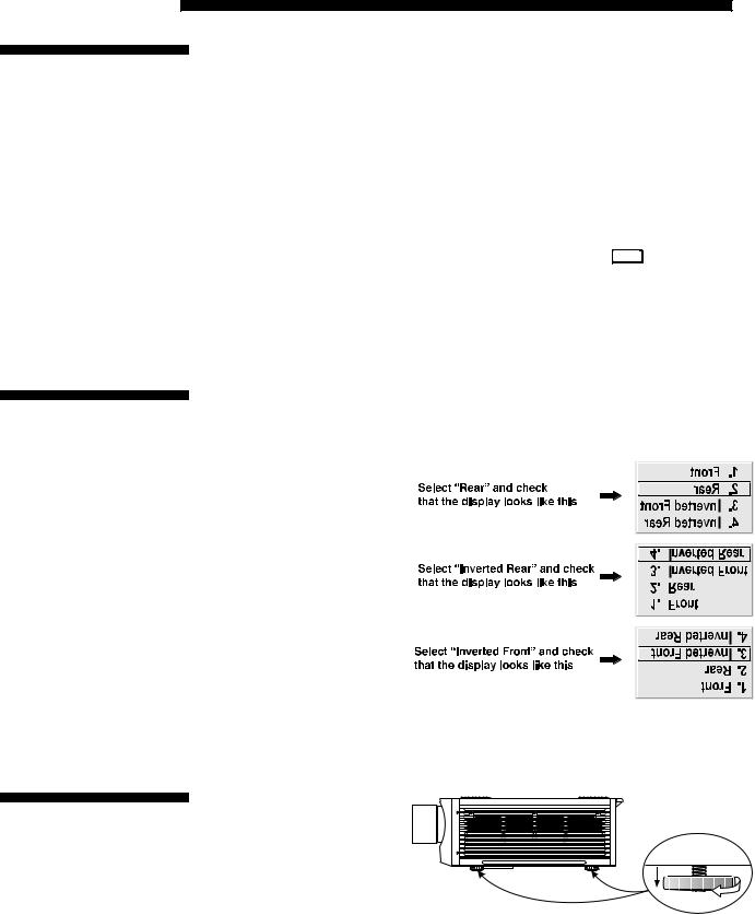
INSTALLATION AND SETUP
2.5Power Connection
2.6Operating Orientation
2.7Leveling
Plug the projector’s high-current line cord into the line input socket located in the lower right corner of the rear panel of the projector, then plug the 3-pronged end of the line cord into a grounded AC outlet. Input voltage to X3/X4/S3/S4 models must be capable of 100-240 VAC. For all other models, it must be 200-240 VAC. Use the proper power source and the high-current rated line cord provided. See Section 5, Specifications for all power requirements.
 WARNING
Do not attempt operation if the AC supply and cord are not within the specified voltage and power range.
 Caution for Shutdowns: Once the projector is turned off ( Power* ), the lamp cooling fans will continue to run for approximately five minutes to ensure that the projector and lamp have sufficiently cooled, at which point the fans will automatically shut off. To avoid thermal stress that can lead to premature lamp failure, never unplug the line cord while the lamp cooling fans are running, and never unplug to power down.
The projector is set up at the factory for use in a front screen, floor mount orientation. If your initial installation is ceiling mount or rear screen, displayed images may be upside down and/or reversed. To correct, you must change the image orientation from within the Menu
Preferences menu (you may prefer to do this before physically installing the projector in its final position/orientation).
In the Menu Preferences Menu, highlight and select the "Image Orientation" pulldown list. Select from Rear, Inverted Rear, Front or Inverted Front according to your intended installation. See Section 3, Operation for further information.
For most installations, the lens surface of the projector is parallel to the screen—this prevents major keystoning of
the image (i.e., an image with non-parallel sides). In addition, the projector must
be kept level from side-to- side in order for the lamp to
function safely. To make small corrections to the projector's level, rotate each leg as necessary to raise or lower. For angled installations, see “Special Mounting” under
2.3, Projector Position and Mounting earlier in this section.
2-24 Roadster/Vista User’s Manual
|
|
|
|
|
|
|
|
|
|
|
|
|
|
|
|
|
|
|
|
|
|
INSTALLATION AND SETUP |
|||||||
|
|
|
|
|
|
|
|
|
|
|
|
|
|
|
|
|
|
|
|
|
|
||||||||
|
|
|
Once the projector is properly set up and producing an image, you are ready to make |
||||||||||||||||||||||||||
|
|
|
|||||||||||||||||||||||||||
|
2.8 |
Zoom, Focus & |
|||||||||||||||||||||||||||
|
quick lens adjustments. Refer to 3.3, Using the Keypad and 3.4, Navigating the |
|
|||||||||||||||||||||||||||
|
|
Lens Offset |
Menus if you are unfamiliar with using the keypad and menu system. |
|
|||||||||||||||||||||||||
|
|
Zoom ' NON-MOTORIZED: If you have a zoom lens installed, turn the textured ring of the lens |
|||||||||||||||||||||||||||
|
|
|
barrel to decrease or increase the size of the image at the current throw distance. |
|
|||||||||||||||||||||||||
|
|
|
MOTORIZED: If you have a zoom lens installed, press Lens |
|
to display the Lens Control |
||||||||||||||||||||||||
|
|
|
|
||||||||||||||||||||||||||
|
|
|
|
||||||||||||||||||||||||||
|
|
|
menu. Select the “Zoom” option ( ) and adjust image size as desired with |
|
|
|
|
or |
|||||||||||||||||||||
|
|
|
|
|
|||||||||||||||||||||||||
|
|
|
|
|
|
|
|
|
|
. Refer back to Figure 2.1. |
|
||||||||||||||||||
|
|
|
|
|
|
|
|
|
|
|
|
|
|
|
|
|
|
|
|
|
WARNING |
|
|||||||
|
|
|
|
|
|
|
|
|
|
|
|
|
|
|
Keep fingers away from the lens opening when |
|
|||||||||||||
|
|
|
|
|
|
|
|
|
|
|
|
|
|
|
|
operating the motorized zoom function. |
|
||||||||||||
|
|
Focus ' NON-MOTORIZED: Near the lens opening, turn the lens focus tab until the image is as |
|||||||||||||||||||||||||||
|
|
|
sharp as possible. |
|
|
|
|
|
|
|
|
|
|
|
|
|
|
|
|||||||||||
|
|
|
MOTORIZED: Press Lens |
|
to display the Lens Control menu. Adjust image clarity as |
||||||||||||||||||||||||
|
|
|
|
||||||||||||||||||||||||||
|
|
|
|
||||||||||||||||||||||||||
|
|
|
desired with |
|
|
|
|
or |
|
|
|
|
|
. Refer back to Figure 2.1. |
|
||||||||||||||
|
|
|
|
|
|
|
|
|
|
|
|||||||||||||||||||
NOTES: 1) Initially, your image may be so blurry you cannot recognize the “Focus” menu option. Remember that Lens activates the “Focus” control (#1)—from here, press  or
or  to adjust. 2) If focus is not uniform throughout the image, bore sight is likely poor. Contact your dealer for service.
Lens Offset ' Lens offsets move the lens and image. Try to achieve the desired overall image position and best brightness while maintaining a rectangular image. If the brightness looks uneven, or the edges do not look perfectly straight, the projector may not be in the optimal position for your screen. See 2.3, Projector Position and Mounting for full details. Lens offset ranges are also listed on page 5-1.
NON-MOTORIZED: To relocate the image, turn either or both of the front knobs adjacent to the lens. The top knob “Vertical” will raise or lower the image, the bottom knob “Horizontal” will shift the image left or right.
MOTORIZED: Press Lens to display the Lens Control menu. Select either lens offset
option ( or ) and move the image as desired with |
or |
. Refer back to |
Figure 2.1. |
|
|
Other display adjustments are available through keypad commands and on-screen menus—refer to Section 3, Operation.
Intelligent Lens SystemTM ' NOTE: Requires motorized lens.
(ILSTM)
Once you’ve defined lens settings for the current display, you can automatically recall these positions whenever you use this channel. This Intelligent Lens SystemTM (ILSTM) function is particularly useful if you are working with a variety of source types that may differ in size and/or aspect ratio, since the custom lens settings you’ve chosen for any channel will be quickly and accurately applied whenever you use that channel.
ENABLING ILSTM : In the Lens Control menu, enable the “Intelligent Lens System” option (highlight it and press Enter ). This will add the 4 lens positions—focus, zoom,
Roadster/Vista User’s Manual 2-25

INSTALLATION AND SETUP
horizontal and vertical offset—to the current channel settings recorded in projector memory (see 3.5, Using Inputs and Channels if you are unfamiliar with channels). The lens will then automatically reposition itself according to these lens settings each time you use this channel. The ILSTM is a global function—any lens settings you subsequently define for other channels will also be recalled whenever you use those channels.
You can still change lens settings as usual when the ILSTM is enabled. Changes will be recalled the next time you use the channel.
DISABLING ILSTM : To use consistent zoom, focus, and offset settings for all channels, delete the “Intelligent Lens System” checkmark (highlight the option and press Enter ). The lens will not move until you adjust one of its settings.
Operating Tips for Lens Settings and ILSTM
NOTE: Accurate ILSTM performance requires a calibrated lens mount. Calibrate after installation of a lens, and repeat if the lens is moved or bumped. See Section 3.
When defining the focus, zoom, horizontal offset and vertical offset slidebar settings for a given channel, keep in mind the following considerations for optimized ILSTM performance:
•The lens mount must be calibrated.
•When decreasing ( ), values are always even (1004-1002-1000-etc.).
•When increasing ( ), values are always odd (1001-1003-1005-etc.).
•Lens movements begin slowly and subtly before reaching full speed—changes may not be evident on screen until after a second or two of  or
or  .
.
•When holding  or
or  , lens movement gradually accelerates.
•As with any setting, you can directly enter a value using the numbers on the keypad, if desired. Press Enter before and after.
•Because of how gears function, movement to an even value is always approached from a higher value, even if the direction of lens movement must reverse to do this. Likewise, an odd value is approached from a lower value. This protocol helps ensure ILSTM accuracy. In general:
◊If decreasing to an odd value, movement will reverse its approach.
◊If increasing to an even value, movement will reverse its approach.
•To make small adjustments for ILSTM recall, always maintain the current odd or even status for the new value—this will prevent the lens from reversing at a point very near to the requested setting and settling in the area of extra travel
known as the “backlash” zone, an area which is not recognized by the ILSTM . For accurate tweaking of an odd setting, press  . If even, press
  .
.
FOR EXAMPLE: If the current setting is 1001 and you enter 1002, the lens must move slightly beyond the requested setting before quickly reversing back down to 1002. Although 1002 will appear in the menu, the physical location of the lens will not be accurately recalled by the ILSTM.
Instead, if you need to slightly increase a current odd setting (such as 1001), either press  as often as necessary or go to a nearby odd setting (1003, 1005, etc.) rather than switching to an even setting (1002, 1004, etc.). This technique will prevent the lens from reversing and settling in the backlash zone.
2-26 Roadster/Vista User’s Manual
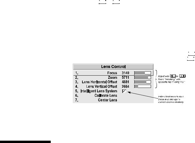

 INSTALLATION AND SETUP
•Try to release the  or
or  key before reaching a desired lens setting, then continue as necessary with small incremental adjustments in the same direction. If you “overshoot” slightly, do not reverse and “tweak” into place unless you have overshot beyond the backlash zone (which can vary from 10 to 600 increments, depending on the function). Otherwise, the ILSTM function will not recognize the final “tweaked” value when you return to this channel, and lens performance will appear inaccurate. In general, use small “incremental” fine-tuning only if the direction of lens movement has not changed during an adjustment. See Figure 2.26.
Alternatively, simply enter a new position to reverse direction. For example, if
the current setting is 2000, enter 2001 to start moving up—then press  . If current setting is 2001, enter 2000 to start moving down—then press
  .
.
2.9Serial Port Connections
Figure 2.26. Lens Settings and the ILSTM
•When adjusting lens offsets, slidebar values will not reach extremes of 0 or 9999. This is normal and does not mean that corresponding lens mount movements failed to reach their physical extremes.
NOTE: Communication software is required for serial control. Contact your dealer for details.
You may wish to use equipment other than the keypad for controlling the projector or for performing other special functions. Such equipment—such as most personal computers—requires a serial interface for sending and receiving communications through the serial ports on the projector. Note that there are two different types of serial communication ports on this projector as described below.
If using a computer ' RS-232 Ports
From most computers, connect an RS-232 serial communication cable between the computer and the projector serial port labeled RS-232 IN—this 9-pin D connector port is located near the bottom center of the projector's rear control panel (see Figure 2.27). Then set the projector baud rate to match that of the computer (changing the baud rate is described in 3.7, Configuring System Parameters.
NOTE: Refer to Appendix D for complete cable wiring details.
Roadster/Vista User’s Manual 2-27
 Loading...