


HD10K-M
Table of contents
 Loading...
M-Series
USER MANUAL
020-100009-01


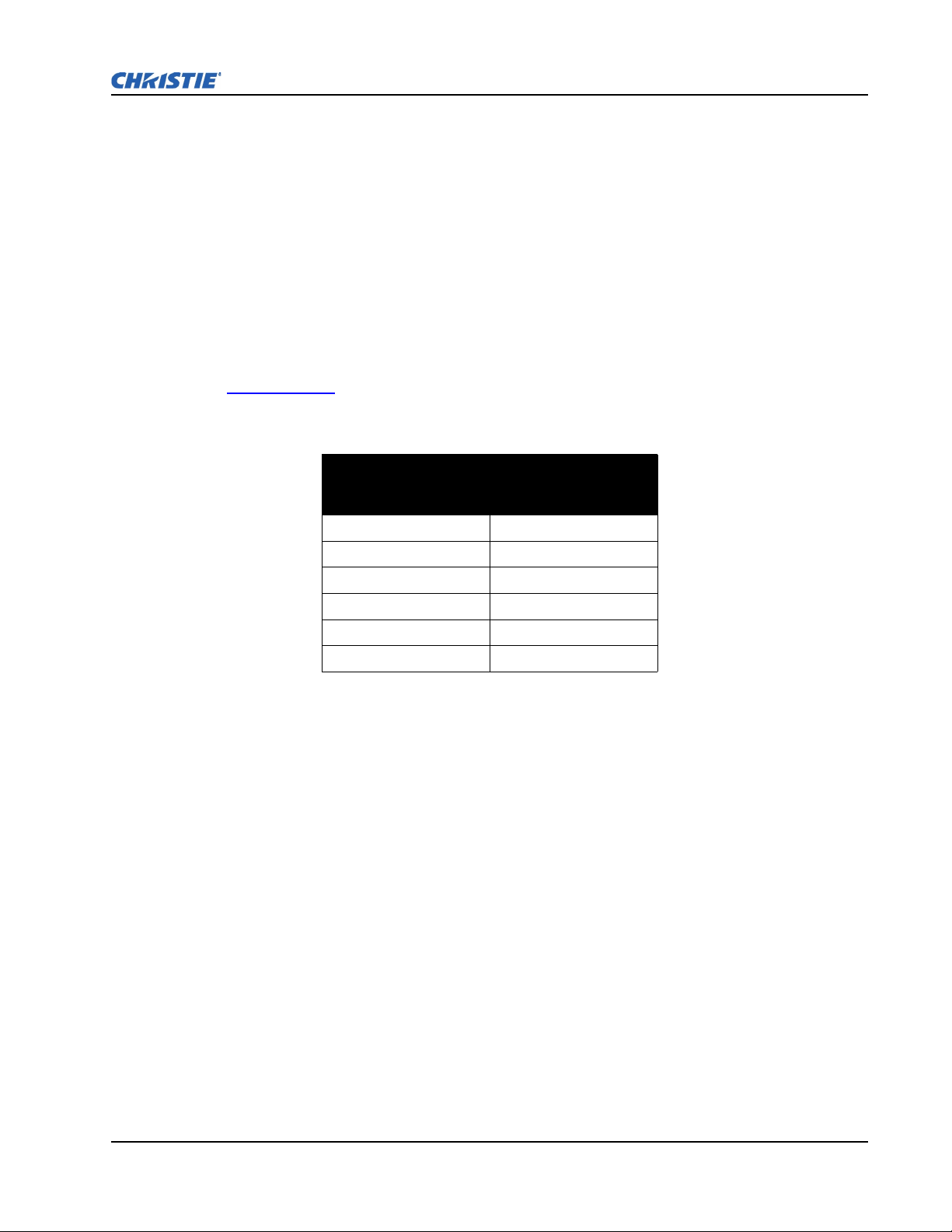
China RoHS Compliance Information
␂ℝ₼⦌ᇵ䟄≰㋾ℶ❐㻰㩢㘶Ⓟ丰䚕┭㽤ᇶ䤓広㢝
㦘㹡㦘⹂䓸德㒥⏒侯
捷ↅ⚜䱿
杔
᧤Pb᧥㻭᧤Hg᧥柘᧤Cd᧥
⏼ↆ杻
᧥
⮩䅃勣啾
᧤
᧥
⮩䅃ℛ勣
啾搩
᧤
᧥
x Environmentally Friendly Use Period
䘾≬∎䞷㦮棟
The year number in the centre of the label indicates the Environmentally Friendly
Use Period, which is required to mark on the electronic information product sold in
China according to the China RoHS regulations.
㦻㪖㉦₼嫷䯉䤓㟿㢾㫈㗽ᇵ䟄≰㋾ℶ❐㻰㩢㘶Ⓟ丰䚕┭㽤ᇶ᧤2006 2
㦗 28 㡴᧥ⅴ♙ᇵ䟄≰㋾ℶ❐㻰㩢㘶Ⓟ㪖幕尐㻑ᇶ᧤2006 11 㦗 6 㡴᧥Ⓟ
⸩䤓ᇬ抑䞷ℝ⦷₼◝ⅉ㺠␀✛⦌⬒␔枏➽䤓䟄≰㋾ℶ❐䤓䘾≬∎䞷㦮棟ᇭ
x Material Concentration Values Table
㦘㹡㦘⹂䓸德⚺摞嫷
Part Name
Power Supply
Switch interlock
Harness/cable
Panel Driver PCB
Passive black
plane PCB
Lamp driver
LCD control panel
Blower/Fan
Sensor
Light engine
Integrator
Dynamic iris
Auxiliary optics
Lamp
Projection lens
Motorized lens
mount
Remote control IR
Mechanical
enclosure*
Note:
O : indicates that the concentration value of the particular hazardous substance contained in all the homogeneous materials for this part,
according to EIP-A, EIP-B, EIP-C, is below the stipulated levels in China SJ/T11363-2006.
嫷䯉年㦘㹡㦘⹂䓸德⦷年捷ↅ㓏㦘⧖德㧟㠨₼䤓⚺摞⧖⦷ SJ/T11363-2006 屓⸩䤓棟摞尐㻑ⅴₚᇭ
X: indicates that the concentration value of the particular hazardous substance contained in all the homogeneous materials for this part,
according to EIP-A, EIP-B, EIP-C, may be above the stipulated levels in China SJ/T11363-2006.
嫷䯉年㦘㹡㦘⹂䓸德咂⺠⦷年捷ↅ䤓㩟⧖德㧟㠨₼䤓⚺摞♾厌怔⒉ SJ/T11363-2006 屓⸩䤓棟摞尐㻑ᇭ
* This part uses metallic alloys, which may contain Lead. ⥯年捷ↅ∎䞷摠⻭⚗摠㧟㠨᧨㟔♾厌⚺㦘杔ᇭ
䟄䄟抑揜⣷
␂⸘⏷析
䟄兎/䟄冕
槱㨎洀┷㲰⧦
㡯䄟卛㨎
䋾䄟洀┷㲰⧦
LCD 㘶Ⓟ槱㨎
⛈歝㧉/歝㓖
↯㎮⣷
⏘ⷵㆤ㝝
⏘ⷵ䱾⒕⣷
┷㊐⏘⦗
戔┸⏘ⷵ⣷ↅ
䋾䄟
㔤㈀柫⯃
泻才洀┷柫⯃
㩅
儱⮥兎拴㘶⣷
㧉㬿棓ↅ/⮥⮂
X O O O O O
X O O O O O
X O O O O O
X O O O O O
X O O O O O
X O O O O O
X O O O O O
X O O O O O
X O O O O O
X O X O O O
X O X O O O
X O O O O O
X O X O O O
X X O O O O
X O X O O O
X O O O O O
X O O O O O
X O O O O O
Material Concentration
(
(Cr 6+
)
PBB
PBDE


TABLE OF CONTENTS
1 Introduction
1.1 Using this Manual............................................................................................................1-2
1.1.1 Labels and Markings................................................................................................1-2
1.1.2 Typographical Notations..........................................................................................1-2
1.2 Purchase Record and Service Contacts............................................................................1-2
1.3 Projector Overview ..........................................................................................................1-3
1.3.1 Main Features...........................................................................................................1-3
1.3.2 How the Projector Works.........................................................................................1-4
1.4 Other Components ...........................................................................................................1-4
2 Installation and Setup
2.1 Projector Quick Setup and Installation ............................................................................2-2
2.2 Detailed Setup and Installation ........................................................................................2-6
2.2.1 About the Projector ..................................................................................................2-6
2.2.2 Installation Considerations.......................................................................................2-8
2.2.3 Projector Position and Mounting .............................................................................2-11
2.2.4 Mounting..................................................................................................................2-17
2.2.5 Adjusting Projector Height/Tilt ...............................................................................2-17
2.2.6 Basic Optical Alignment..........................................................................................2-18
2.2.7 Advanced Optical Alignment...................................................................................2-19
2.2.8 Powering Down........................................................................................................2-21
2.2.9 Connecting Communications...................................................................................2-22
2.3 Connecting Sources .........................................................................................................2-30
3 Operation
3.1 Using the Remote Keypad or Built-In Keypad................................................................3-2
3.1.1 Remote Keypad Commands.....................................................................................3-5
3.2 Navigating the Menus......................................................................................................3-10
3.3 Using Inputs and Channels ..............................................................................................3-14
3.3.1 Channel Setup Menu................................................................................................3-16
3.4 Adjusting the Image.........................................................................................................3-20
3.4.1 Size and Position Menu............................................................................................3-21
3.4.2 Image Settings Menu ...............................................................................................3-25
3.5 Configuration - Adjusting System Parameters and Advanced Controls.........................3-36
3.6 Working with PIP or Input Switching .............................................................................3-50
3.6.1 Input Switching & PIP Menu...................................................................................3-51
3.7 Lamp ................................................................................................................................3-53
3.8 Status................................................................................................................................3-54
3.9 Using Multiple Projectors................................................................................................3-55
3.10 Remote Control of the Projector....................................................................................3-58
3.11 Alarm Conditions...........................................................................................................3-59
M-Series User Manual i
020-100009-01 Rev. 1 7/08

TABLE OF CONTENTS
4 Maintenance
4.1 Safety Warnings and Guidelines......................................................................................4-2
4.1.1 General Precautions .................................................................................................4-2
4.1.2 AC /Power Precautions ............................................................................................4-3
4.1.3 Lamp Precautions.....................................................................................................4-3
4.2 Maintenance of the Cooling System................................................................................4-4
4.2.1 Ventilation................................................................................................................4-4
4.2.2 Optional Filters ........................................................................................................4-4
4.3 Maintenance of Optics .....................................................................................................4-5
4.3.1 Optical (Excluding Lens) .........................................................................................4-5
4.3.2 Cleaning the Lens.....................................................................................................4-6
4.4 Replacing the Lamps .......................................................................................................4-6
5 Troubleshooting
5.1 Power ...............................................................................................................................5-2
5.1.1 Projector Does Not Power ON.................................................................................5-2
5.2 Lamp ................................................................................................................................5-2
5.2.1 Lamp Does Not Ignite..............................................................................................5-2
5.2.2 Lamp Suddenly Turns OFF......................................................................................5-2
5.2.3 Flicker, Shadows Or Dimness..................................................................................5-2
5.2.4 LiteLOC™ Does Not Seem to Work .......................................................................5-3
5.3 LCD .................................................................................................................................5-3
5.3.1 Blank Screen, No Menu Displaying ........................................................................5-3
5.4 Remote Keypad................................................................................................................5-3
5.4.1 Remote Keypad Does Not Seem to Work ...............................................................5-3
5.5 OSD .................................................................................................................................5-3
5.5.1 The OSD Menu does not display .............................................................................5-3
5.6 Ethernet............................................................................................................................5-4
5.6.1 Trouble Establishing Communication with Projector..............................................5-4
5.7 Displays ...........................................................................................................................5-4
5.7.1 The projector is on but there is no display ...............................................................5-4
5.7.2 Severe Motion Artifacts ...........................................................................................5-4
5.7.3 Image Appears ‘Squeezed’ or Vertically Stretched into Center of Screen..............5-4
5.7.4 The Display is Jittery or Unstable............................................................................5-5
5.7.5 The Display is Faint .................................................................................................5-5
5.7.6 The Upper Portion of the Display is Waving, Tearing or Jittering..........................5-5
5.7.7 Portions of the Display are Cut OFF or Warped to the Opposite edge....................5-5
5.7.8 Display Appears Compressed (Vertically Stretched) ..............................................5-5
5.7.9 Data is Cropped from Edges ....................................................................................5-5
5.7.10 Display Quality Appears to Drift from Good to Bad, Bad to Good ......................5-5
5.7.11 Display has Suddenly Frozen.................................................................................5-5
5.7.12 Colors in the Display are Inaccurate .....................................................................5-6
5.7.13 Values in Color Saturation slide bars vary overtime .............................................5-6
5.7.14 Display is Not Rectangular ...................................................................................5-6
M-Series User Manual ii
020-100009-01 Rev. 1 7/08

TABLE OF CONTENTS
5.7.15 Display is “Noisy” ................................................................................................5-6
6 Specifications
6.1 Image Performance ..........................................................................................................6-2
6.1.1 Pixel Format ...........................................................................................................6-2
6.1.2 Brightness (ANSI Lumens) ....................................................................................6-2
6.1.3 Contrast ....................................................................................................................6-2
6.1.4 Luminance Uniformity.............................................................................................6-3
6.1.5 Color Uniformity......................................................................................................6-3
6.1.6 Color Primaries ........................................................................................................6-3
6.1.7 Gamma .....................................................................................................................6-3
6.1.8 Grayscale/Color Resolution .....................................................................................6-3
6.1.9 Color Temperature ...................................................................................................6-3
6.1.10 Convergence...........................................................................................................6-4
6.1.11 Blemishes ...............................................................................................................6-4
6.1.12 Pixel Defects ..........................................................................................................6-5
6.1.13 Image Artifacts.......................................................................................................6-5
6.1.14 Picture Centering....................................................................................................6-5
6.2 Feature Set .......................................................................................................................6-5
6.2.1 Airflow ....................................................................................................................6-5
6.2.2 Air Filters (Optional) ...............................................................................................6-5
6.2.3 Dust Sealing .............................................................................................................6-5
6.2.4 ILS (Intelligent Lens System) ..................................................................................6-6
6.2.5 Projection Lens Compatibility .................................................................................6-6
6.2.6 Dynamic Iris ............................................................................................................6-6
6.2.7 Automatic Fans ........................................................................................................6-7
6.2.8 Automatic Color Filtering........................................................................................6-7
6.2.9 Constant Lamp Output Management .......................................................................6-7
6.2.10 Shutter ...................................................................................................................6-7
6.2.11 Lamps.....................................................................................................................6-7
6.2.12 Status LED .............................................................................................................6-8
6.2.13 Electronics/SW ......................................................................................................6-8
6.3 Image Processor Performance..........................................................................................6-9
6.4 Input (Source Signal) Compatibility ...............................................................................6-9
6.4.1 Analog (Only) Input.................................................................................................6-9
6.4.2 Twin HDMI Input ....................................................................................................6-9
6.4.3 Dual Link DVI Input................................................................................................6-10
6.4.4 Video Decoder Input................................................................................................6-10
6.4.5 Dual Standard Definition, High Definition or Serial Digital Input..........................6-10
6.5 Control Signal Compatibility ..........................................................................................6-10
6.5.1 Remote Dual Frequency...........................................................................................6-10
6.5.2 Control Receiver ......................................................................................................6-11
6.5.3 RS232.......................................................................................................................6-11
6.5.4 RS422.......................................................................................................................6-11
6.5.5 Ethernet ....................................................................................................................6-11
M-Series User Manual iii
020-100009-01 Rev. 1 7/08

TABLE OF CONTENTS
6.5.6 USB 2.0 Device Port ...............................................................................................6-11
6.5.7 GPIO ........................................................................................................................6-11
6.5.8 DMX512 Interface ..................................................................................................6-11
6.5.9 Built-In Keypad and Display ...................................................................................6-11
6.5.10 AMX/Crestron Support..........................................................................................6-12
6.6 Power Requirements ........................................................................................................6-12
6.6.1 Lamp Specification ..................................................................................................6-13
6.7 Physical Specifications ....................................................................................................6-13
6.7.1 Size...........................................................................................................................6-13
6.7.2 Adjustment ...............................................................................................................6-13
6.7.3 Weight......................................................................................................................6-13
6.7.4 Operating Position....................................................................................................6-13
6.7.5 Cosmetics .................................................................................................................6-13
6.8 Reliability and Serviceability...........................................................................................6-14
6.8.1 Reliability.................................................................................................................6-14
6.8.2 Serviceability ...........................................................................................................6-14
6.9 Environment.....................................................................................................................6-14
6.9.1 Temperature/Humidity/Altitude...............................................................................6-14
6.10 Accessories and Service Components ...........................................................................6-14
6.10.1 Service Components ..............................................................................................6-15
6.11 Regulatory......................................................................................................................6-15
Appendix - GPIO
A.1 GPIO Port........................................................................................................................A-2
M-Series User Manual iv
020-100009-01 Rev. 1 7/08

1 Introduction
This Manual applies to the M-Series projector. Read this manual in its entirety and understand all
warnings and precautions before attempting to operate the projector.
• 1.1 Using this Manual
• 1.2 Purchase Record and Service Contacts
• 1.3 Projector Overview
• 1.4 Other Components
Disclaimer: Every effort has been made to ensure the information in this document is accurate and reliable.
However, the information in this document is subject to change without notice. Christie Digital Systems assumes
no responsibility for omissions or inaccuracies. Updates to this document are published, as required.
M-Series User Manual 1-1
020-100009-01 Rev.1 (07/08)

1.1 USING THIS MANUAL
USERS/OPERATORS: This manual is intended for trained users operating professional high-brightness
projection systems. Such users may also be trained to replace the lamp and air filter, but cannot install
the projector or perform any service functions on the M-Series projector.
SERVICE: Only trained and qualified Christie service technicians knowledgeable about all potential
hazards associated with high voltage, ultraviolet exposure and high temperatures generated by the
lamp and associated circuits are authorized to 1) assemble/install the projector and 2) perform service
functions inside the projector.
1.1.1 Labels and Markings
Observe and follow all warnings and instructions marked on the projector.
The exclamation point within the equilateral triangle indicates a warning and refers to related
operating/maintenance instructions in the User Manual.
The lightning flash and arrowhead symbol within the equilateral triangle indicates non-insulated
“dangerous voltage” within the projector’s enclosure that may be of sufficient magnitude to constitute
a risk of electric shock.
Section 1: Introduction
1.1.2 Typographical Notations
The following notations are used throughout this manual:
• Keypad commands and PC keystrokes appear in bold small caps, such as POWER, INPUT, ENTER etc.
• References to specific areas of the document appear italicized and underlined. When viewed
online the text appears in blue indicating a direct link to that section.
For example, 6 Specifications.
• References to other documents appear italicized and bold, such as Christie User Manual.
• References to software menus and available options appear bold, such as Main Menu,
Preferences.
• User input or messages that appear on screen, in status display units or other control modules
appear in Courier font.
For example. “No Signal Present”, Login: christiedigital.
• Error codes, LED status appear in bold, e.g.
LP, A1 etc.
• Operational states of modules appear capitalized, such as “power ON, power OFF”.
• Signal words, such as Warning, Caution and Notes are used in this manual to point the reader to
specific information or instructions that warn of safety related hazards which may be present and
how to avoid them.
1.2 PURCHASE RECORD AND SERVICE CONTACTS
Whether the projector is under warranty or the warranty has expired, Christie’s highly trained and
extensive factory and dealer service network is always available to quickly diagnose and correct
projector malfunctions.
M-Series User Manual 1-2
020-100009-01 Rev.1 (07/08)
Should you encounter a problem with any part of the projector, contact your dealer. In most cases,
servicing can be performed on site. If you have purchased the projector, fill out the information below
and keep with your records.
Table 1.1 Purchase Record
Dealer:
Dealer Phone Number:
Projector Serial Number*:
Purchase Date:
Installation Date:
* The serial number can be found on the rear of the projector.
Table 1.2 Ethernet Settings
Default Gateway
DNS Server
Projector Address
Projector Mgmt IP Address
Subnet Mask
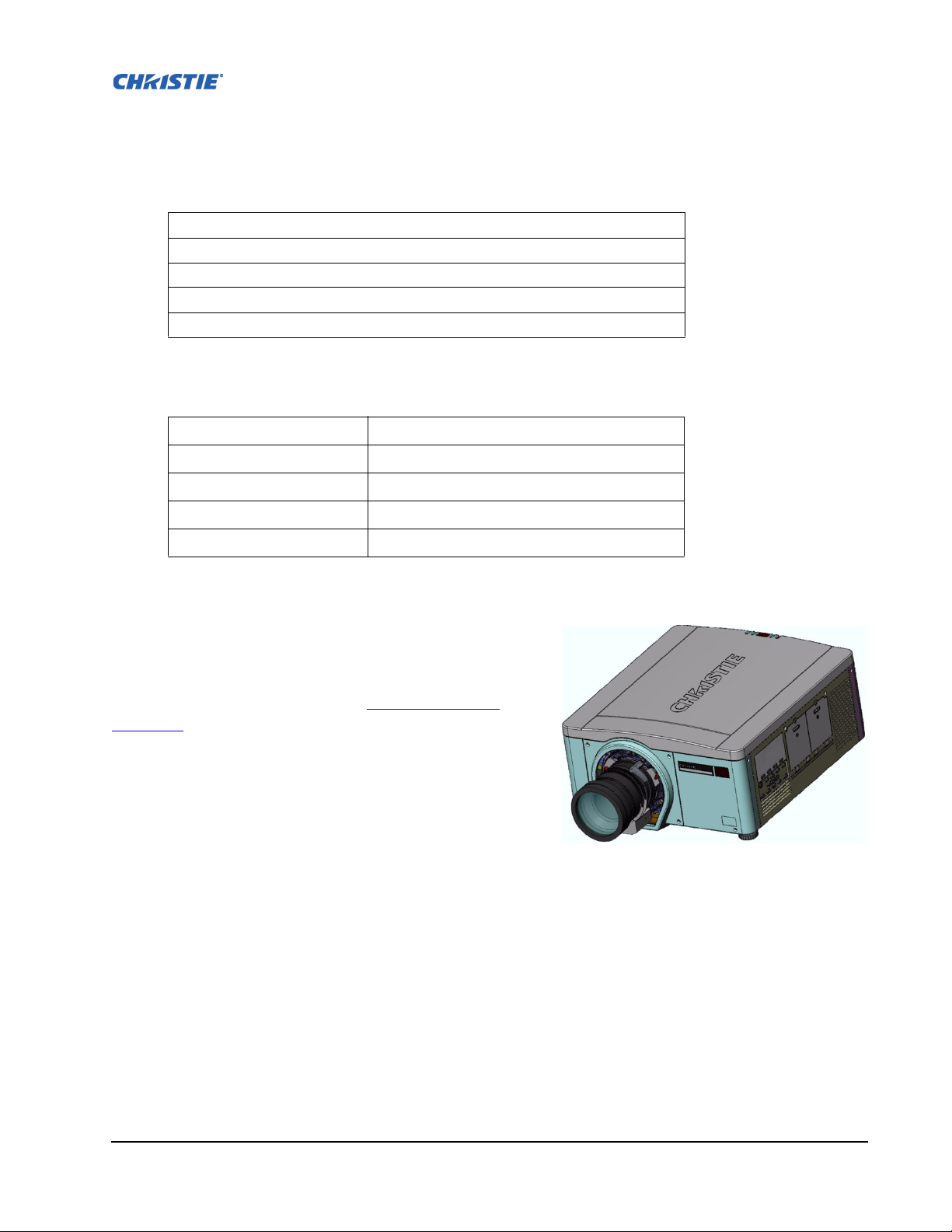
1.3 PROJECTOR OVERVIEW
The M-Series is a family of high resolution video/graphics 3
chip HD and SXGA+ projectors, see Table 1.3 M-Series
Projectors. These projectors are based on next-generation
DLP® technology provided by Texas Instruments.
1.3.1 Main Features
• Up to 10,000 lumens
• HD (1080p) or SXGA+ resolution
• Dual Mercury lamp illumination with 200W or 350W
options
• Dynamic iris contrast aperture providing up to 10,000:1 contrast ratio
• Ultra-compact design and weight less than 55lbs
• 10-bit image processor electronics with modular design
• Fully sealed optical system
• Active fan control for minimum noise level
• Selectable, motorized yellow notch filter for expanded color gamut
• User interchangeable projection lenses with no-tool mounting
FIGURE 1-1 - M-SERIES
M-Series User Manual 1-3
020-100009-01 Rev.1 (07/08)
• PIP and seamless switching
• LiteLOC™ for constant brightness maintenance
• Intelligent Lens System (ILS)
• Motorized lens mount for all models
• Auto-setup feature
• Integrated ChristieNET
• Networking ability through RS232 and RS422 connectors
• Status LED display on built-in keypad for easy projector status monitoring
• Control with remote keypad, wired remote, or built-in keypad
• Four input slots for Optional Input Modules
Refer to 6 Specifications
for a complete list of technical specifications.
Table 1. 3 M-S e ri es Projectors
Model Name Part Number
DS+6K-M 118-013105-XX
DS+10K-M 118-014106-XX
HD6K-M 118-021104-XX
HD10K-M 118-023106-XX
Roadster HD10K-M 118-042107-XX
Roadster S+10K-M 118-044109-XX
Section 1: Introduction
1.3.2 How the Projector Works
The projector accepts data/graphics and video input signals for projection onto front or rear screens.
Light is generated by dual mercury lamps, then modulated by three Digital Micro-mirror Device
(DMD) panels that provide digitized red, green or blue color information. Light from the "ON" pixels
of each panel is reflected, converged and then projected to the screen through a single front lens, where
all pixels are perfectly superimposed as a sharp full-color image.
1.4 OTHER COMPONENTS
The items listed below are shipped with the projector. Ensure you have received these items before
using the projector.
• IR remote keypad (includes two, 1.5V AA batteries and an XLR to mini-stereo cable for conver-
sion to wired)
•Line cord
• Warranty Card
• Lens Mount Security Screw (M6x10mm long, Qty. 2)
• Lens Mount Security Screw (5mm Hex, Qty. 1)
M-Series User Manual 1-4
020-100009-01 Rev.1 (07/08)

2 Installation and Setup
This section explains how to install, and setup the projector for delivery of superior image
quality.
• 2.1 Projector Quick Setup and Installation
• 2.2 Detailed Setup and Installation
• 2.3 Connecting Sources
M-Series User Manual 2-1
020-100009-01 Rev.1 (07/08)
Section 2: Installation and Setup
2.1 PROJECTOR QUICK SETUP AND INSTALLATION
The following instructions are for those preferring a quick setup. Refer to the remaining subsections
for detailed setup instructions.
Always power down the projector and disconnect all power sources before
Refer to Safety Warnings and Guidelines in Section 4.
STEP 1 - INSTALLING A PROJECTION LENS
The projection lens, shipped separately from the projector, must be installed prior to setting up the
projector.
Remove the lens plug from the lens opening in the projector before installing the lens. Retain the
lens plug for projector transportation to protect the projector’s optical components from dust and
debris.
DANGER
servicing or cleaning.
WARNING
IMPORTANT! The lens seals the projector, preventing contaminants from entering the interior of the
projector. Never operate a projector without a lens.
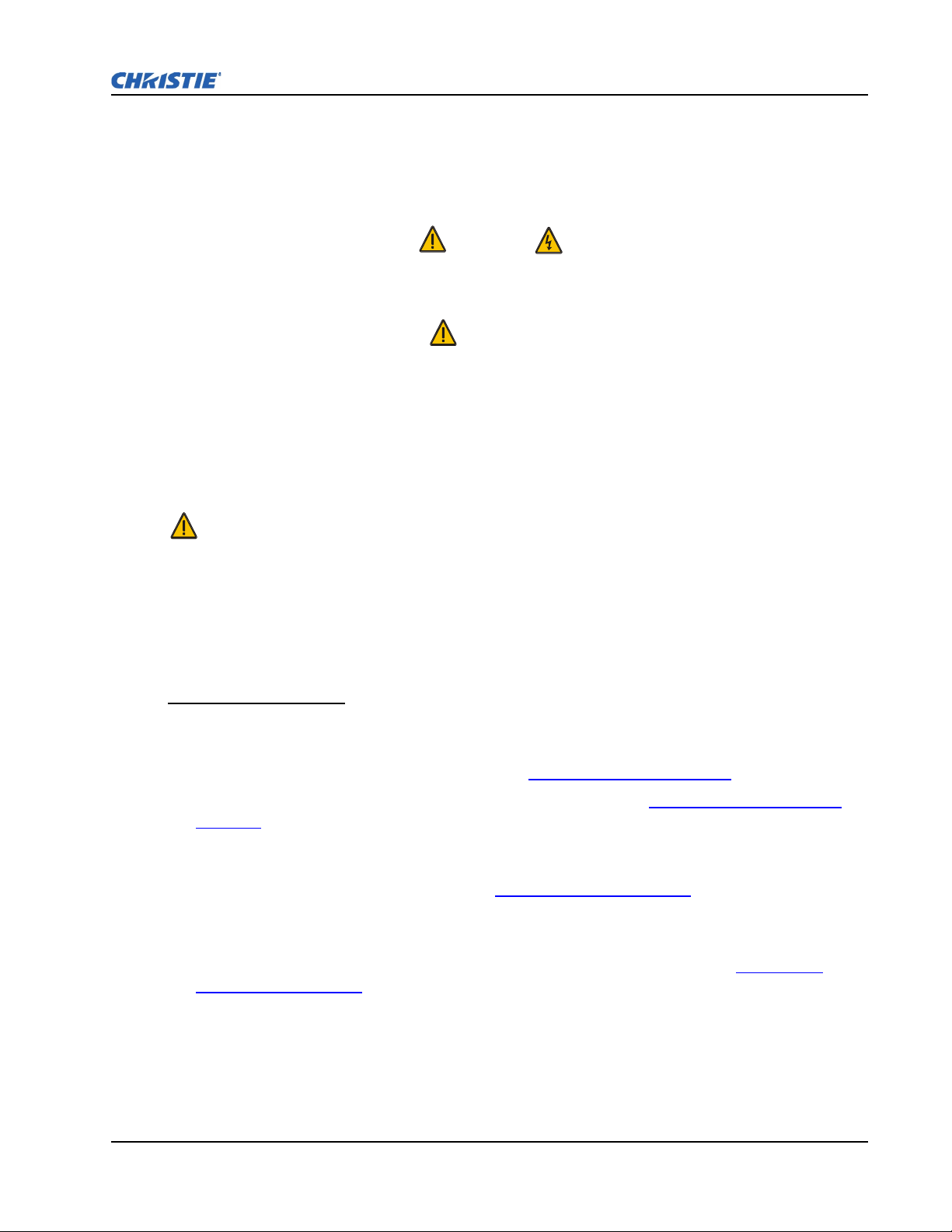
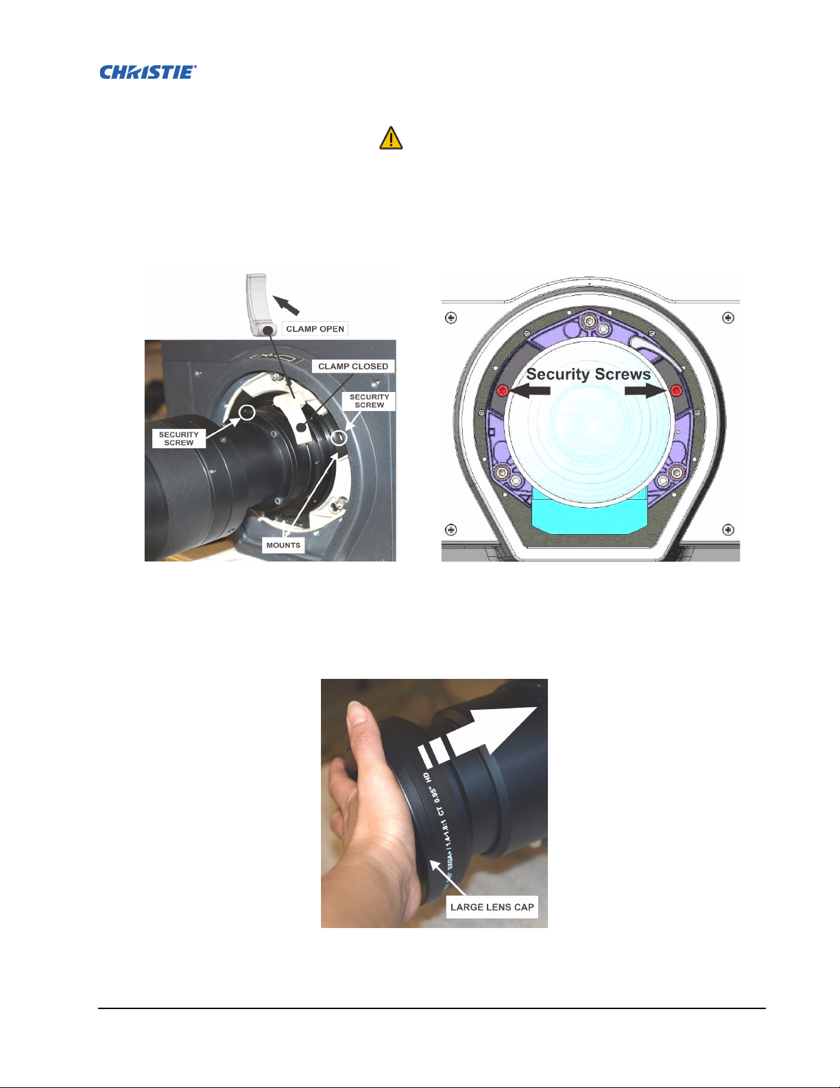
LENS INSTALLATION
1. Remove the small lens cap from the lens. Keep the large lens cap on the lens to protect it during
installation.
2. Rotate the lens clamp to the OPEN position, see Figure 2-1 - Lens Installation
.
3. Remove and retain the 2 security screws from the lens mount, see Figure 2-2 - Security Screw
Location.
4. Align the lens interface plate with the lens mount. Align the lens electrical connector with the
mating connector on the lens mount. Fully insert the assembly straight into the lens mount opening
without turning. Press using your hand, see Figure 2-3 - Lens Placement
.
5. While holding the lens flat against the lens mount, rotate the lens clamp clockwise to lock the lens
assembly in place.
6. For added stability such as motion applications, fasten the security screws, see Figure 2-2 -
Security Screw Location provided on the lens-mount, using the tool provided. NOTES: 1)
Recommended for heaviest lenses such as 0.73:1 and 1.2:1. 2) Security screws MUST be installed
when hoisting the projector overhead, or installing the projector in an overhead position.
7. Remove the large lens cap.
M-Series User Manual 2-2
020-100009-01 Rev.1 (07/08)
WARNING
Use of the lens security screws is required if the projector is hoisted or installed
in an overhead position
F
IGURE 2-1 - LENS INSTALLATION FIGURE 2-2 - SECURITY SCREW LOCATION
FIGURE 2-3 - LENS PLACEMENT
M-Series User Manual 2-3
020-100009-01 Rev.1 (07/08)

Section 2: Installation and Setup
STEP 2 - POSITIONING THE PROJECTOR
WARNING
2 people are required to safely lift and install the projector.
Place the projector on a sturdy, level surface and position it so that it is perpendicular to the screen at a
suitable distance. The further back the projector is positioned for the screen, the larger the image will
be.
To level the projector adjust its 3 feet. With the projector positioned perpendicular to the screen the
image will appear rectangular instead of keystoned.
For more detailed instructions on positioning the projector refer to 2.2.3 Projector Position and
Mounting later in this section.
STEP 3 - CONNECTING A SOURCE
Located at the back of the projector is the input panel where all source connections are made. Each
input is clearly labeled for easy identification. Depending on the type of option card installed, connect
your source using the appropriate cable(s), as follows:
• Analog Input Card, connect 3-, 4-, or 5-wire RGB source to Red/Pr, Green/Y, Blue/Pb, H/C and V
using 3, 4 or 5 BNC connectors as required.
• Dual SD/HD - SDI Input Card, connect SDI (Serial Digital Interface) cable to one of the two
inputs, 1-IN or 2-IN. Both standard-definition (SD) and high-definition (HD) signals are accepted
and automatically recognized on either input.
• Dual Link DVI Input Card, connect a single or dual DVI video signal to the DVI-I connector, an
analog video signal to the DVI-I connector or an analog video signal to the VGA connector. The
DVI signal may contain HDCP (High-Bandwidth Digital Content Protection).
• Twin HDMI Input Card, connect HDMI (High-Definition Multimedia Interface) cable to one of
the two inputs, 1-IN or 2-IN.
• Video Decoder Input Card, depending on the source you can apply the following;
• Composite video source to 1-CVBS, using a BNC Cable NOTE: Same signal can be used on 4, 5
or 6 when input is selected as CVBS.
• A component signal on Inputs 4(Pr), 5(Y), 6(Pb) using BNC Connectors. NOTE: Grouped as a
component input, YPbPr.
• S-Video to one of the two, 2-SVID or 3-SVID using S-Video cable.
• S-Video using two BNC cables, with Luma (Y) connected to 4 (Sy) and Chroma (C) connected to
6 (Sc). NOTE: Must be grouped as 1 S-Video + 1 CVBS.
Refer to 2.3 Connecting Sources
for more details.
M-Series User Manual 2-4
020-100009-01 Rev.1 (07/08)

STEP 4 - CONNECTING THE LINE CORD
IMPORTANT: Use the line cord provided with the projector, or ensure you are using a line cord,
power plug and socket that meet the appropriate rating standards. NOTE: Listed on the license label.
Connect the projector's line cord to the AC receptacle at the AC inlet of the projector, then push the
wire clip over the plug to retain it. This prevents the line cord from inadvertent disconnection. Plug the
3-pronged plug end into a suitably rated grounded AC receptacle. Switch the projector ON. The switch
is located just above the AC receptacle.
WARNING
Do not attempt operation if the AC supply and cord is not within the specified
ratings. On power down, wait 5-10 minutes for the fans to turn OFF before
unplugging the projector. Always switch off the projector before unplugging the
AC line cord.
STEP 5 - POWER UP
After the AC Power has been switched on, the LCD display above the keypad indicates “Please wait”
and the 4 LED status indicators on the top cover window switch on to amber. These indicate that the
projector is changing its state from powered down to standby. The message “Standby Mode” appears
in the display when the projector has completed its initialization and is ready for power up. The 2 lamp
status LEDs will go off to indicate that the lamps are off. The Power status LED will show amber,
indicating that the projector is in standby mode. The shutter LED will display amber, indicating the
shutter is closed. Press and hold the power button on the keypad or remote for 2 seconds, or press twice
quickly. The lamps will power on and the fans will come on. Note: See Section 3 Operation
description of the status indicators.
for a full
NOTE: The default settings for the projector are to perform a lens calibration after the insertion of a
new lens. If this is the first time the projector has been powered up with the lens, expect a short period
(about 15 seconds) where the lens will move slightly.
STEP 6 - SELECTING A SOURCE
Press one of the input keys on the remote or built-in keypad to select and display the image for the
source you connected in Step 3.
STEP 7- ADJUSTING IMAGE
Adjust the image settings, such as Brightness, Contrast, Gamma, Focus, Zoom etc. using the direct
keys on the remote or built in keypad. NOTE: Refer to Section 3 Operation
for more details.
M-Series User Manual 2-5
020-100009-01 Rev.1 (07/08)
2.2 DETAILED SETUP AND INSTALLATION
DANGER
Always power down the projector and disconnect all power sources before
servicing or cleaning.
WARNING
Refer to Safety Warnings and Guidelines in Section 4.
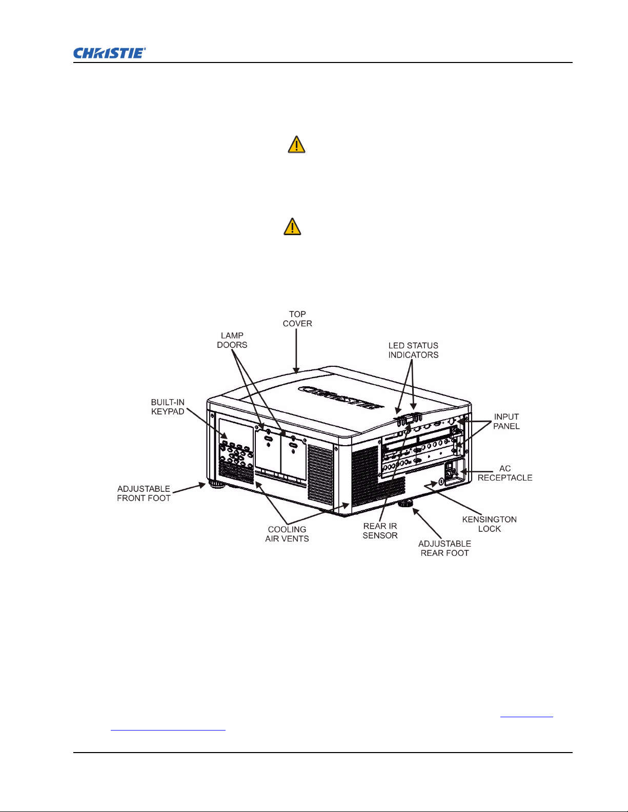
2.2.1 About the Projector
Section 2: Installation and Setup
FIGURE 2-4 - ABOUT THE PROJECTOR - REAR/SIDE VIEW
BUILT-IN KEYPAD
The built-in keypad is located on the side of the projector. Use it similarly to the IR remote to control
the projector. An LCD display is located above the keypad for displaying projector status.
AC RECEPTACLE
The AC receptacle is located at the back of the projector. Use this receptacle to plug in an appropriately
rated line cord. NOTE: The power switch is located above the AC receptacle. Refer to Section 6 –
Specifications for details.
M-Series User Manual 2-6
020-100009-01 Rev.1 (07/08)
ADJUSTABLE FEET
Located on the underside of the projector are three adjustable feet. Raise or lower these feet when
positioning the projector to ensure it is level on all sides so the displayed image will appear rectangular
without any keystone.
Refer to 2.2.5 Adjusting Projector Height/Tilt
for instructions on how to adjust the projector’s feet.
INPUT PANEL
All source connections are made to the input panel located at the back of the projector. Any of the
available optional input cards can be installed in the 4 option card slots. The slots are labelled 1
through 4. All option cards have LEDs to indicate their status.
COOLING AND AIR VENTS
There are numerous air vents located around the projector. It is important these vents remain
unobstructed. Adequate airflow through the projector will prevent it from overheating.
KENSINGTON LOCK ATTACHMENT
Located at the rear of the projector to the left of the AC receptacle, is a Kensington lock attachment
point. This provides the ability to secure the projector against possible theft.
LAMP DOOR
The lamp doors are located at the side of the projector, which provides easy access to the lamp module
for replacement. Refer to Section 4.4 Replacing the Lamps
. The lamp doors are fitted with safety
interlocks which switch the lamp off when the door is opened. The lamp doors are provided with clear
windows to indicate when the lamps are on.
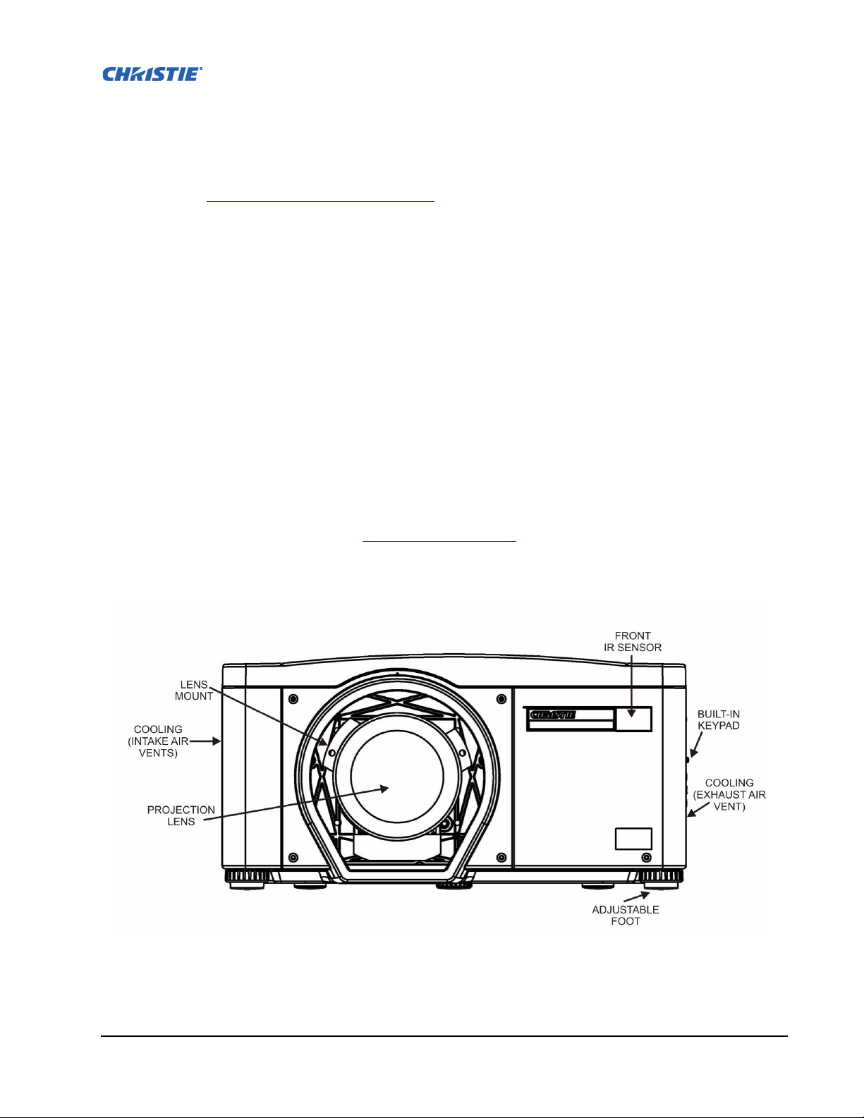
FIGURE 2-5 - ABOUT THE PROJECTOR - FRONT VIEW
M-Series User Manual 2-7
020-100009-01 Rev.1 (07/08)

Section 2: Installation and Setup
FRONT & REAR IR SENSORS
The two IR sensors located on the projector receive transmissions from the IR remote from up to 100
feet away. It is important to keep the transmission path to these sensors unobstructed for uninterrupted
communications with the projector. The rear IR sensor is located at the back of the projector between
the status LEDs and the front IR sensor is located next to the projector’s front nameplate.
PROJECTION LENSES, LENS MOUNT AND OTHER FEATURES
The projector includes a motorized lens mount that allows automated lens control and adjustment:
vertical and horizontal offsets, zoom and focus. The lens mount can be fitted with any one of the
available optional lenses – see Section 6 Specifications
.
• Zoom and Focus – There are two internal lens motors that allow for quick motorized adjustment of
zoom and focus. Adjust zoom to fit the displayed image on the screen and adjust focus to improve
the clarity of the image.
NOTES: 1) The projection lens is shipped separately from the projector. 2) Use the lens cap when
transporting the lens to avoid scratching and damaging the lens, which could affect your displayed
image.3) Motorized lenses should not be adjusted by hand without first setting them for manual
operation, otherwise the zoom and focus motors may be damaged. (Set in Menu ->Configuration-
>Lens Settings ->Manual Zoom/Focus).
• Lens Offset – The motorized lens mount allows vertical and horizontal offset of the displayed
image.
• Shutter – Standard on all models, the shutter allows you to turn the screen absolutely black when in
the “Closed” state.
• Dynamic Iris Contrast Aperture – Enables adjustment of light output and contrast ratio.
2.2.2 Installation Considerations
Proper installation of your projector will ensure the quality of your display. Whether you are installing
a projector temporarily or permanently you should take the following into account to ensure your
projector performs optimally. Choose the installation type that best suits your needs: front or rear
screen, floor mount or inverted mount.
FRONT SCREEN / FLOOR MOUNT INSTALLATIONS
Advantages Considerations
• Easy to set up.
• Can be moved or changed quickly.
• Easy to access.
Shares floor space with audience.
M-Series User Manual 2-8
020-100009-01 Rev.1 (07/08)
FRONT SCREEN / INVERTED MOUNT (CEILING) INSTALLATION
Advantages Considerations
• Does not take up audience space.
• Projector is unobtrusive.
• Projector cannot be accidentally moved.
• Installation is more permanent.
• It is more difficult to access the projector.
REAR SCREEN / FLOOR MOUNT INSTALLATION
Advantages Considerations
• Projector is completely hidden.
• Projector is easily accessed.
• Usually good ambient light rejection.
• Requires separate room or enclosure.
• Installation cost is usually higher.
REAR SCREEN / INVERTED MOUNT (CEILING) INSTALLATION
Advantages Considerations
• Projector is completely hidden.
• Usually good ambient light rejection.
• Requires separate room.
• Installation cost is usually higher.
• More difficult to access projector.
REAR SCREEN / FLOOR MOUNT WITH MIRROR
Advantages Considerations
• Projector is completely hidden
• Usually good ambient light rejection.
• Requires less space behind screen than other rear
screen installations.
• Requires separate room or enclosure.
• Installation cost is usually higher.
• More involved to perform setup.
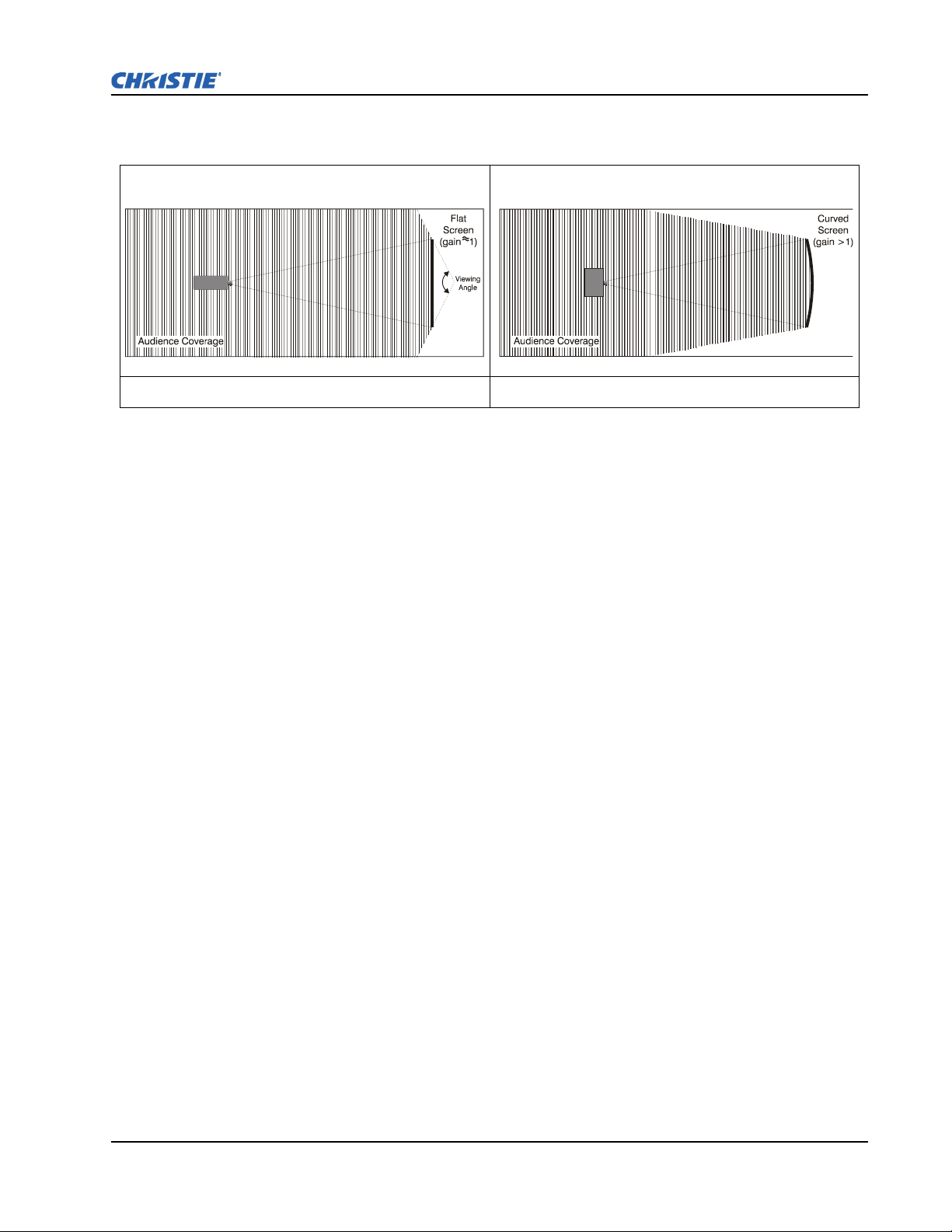
FRONT SCREEN INSTALLATIONS
In front screen installations, the projector and audience are positioned in front of the screen, which can
be flat or curved.
Flat screens offer a gain of about 1.0 with a viewing angle just less than 180°. This type of screen
reflects incident light equally in all directions so the audience can see the display from various angles.
Curved screens have a gain greater than 1.0 with a viewing angle much less than 180°. This type of
screen does not reflect incident light equally in all directions; instead it is concentrated in a viewing
cone. The audience sitting within the viewing cone area will see a brighter image than those sitting just
outside the area.
M-Series User Manual 2-9
020-100009-01 Rev.1 (07/08)
Section 2: Installation and Setup
FIGURE 2-6 - FLAT SCREEN FIGURE 2-7 - CURVED SCREEN
REAR SCREEN INSTALLATIONS
There are two basic types of rear screens: diffused and optical.
A diffused screen has a surface which spreads the light striking it. Purely diffused screens have a gain
of less than 1.0. The advantage of the diffused screen is its wide viewing angle, similar to that of a flat
screen for front screen projection. This type of screen is suitable when a wide viewing angle is required
but there is low ambient room lightening.
Optical screens take light from the projector and redirect it to increase the light intensity at the front of
the screen. This reduces it in other areas. A viewing cone, similar to that of a curved front screen
installation is created. This type of screen is better suited for brightly lit rooms where the audience is
situated within the viewing cone.
SCREEN SIZE
Choose a screen size appropriate for your lens and application. If the projector will be used to display
text information, the image size must allow the audience to recognize all text clearly. The eye sees a
letter clearly if eye-to-text distance is less than 150 times the height of the letter. Small text located too
far from the eye will be illegible at a distance no matter how sharply and clearly it is displayed.
To fill a screen with an image, the aspect ratio of the screen should be equal to the aspect ratio of the
image (expressed as the ratio of its width to its height). Standard video from a VCR has a 4:3 or 1.33:1
aspect ratio. For example, to display a VCR output with a 4:3 aspect ratio onto a 10-foot (3m) high
screen, the width of the screen must be at least 13.3 feet (4m).
AMBIENT LIGHTING
The high brightness of this projector is well suited for locations where ambient lighting might be
considered less than ideal. A typical room with ceiling lights and windows rarely requires special
attention. Contrast ratio in your images will be reduced if stray light directly strikes the screen. For
example, when a shaft of light from a window or floodlight falls on the image. Images may appear
washed out and less vibrant. Avoid or eliminate stray light sources directed at the screen.
M-Series User Manual 2-10
020-100009-01 Rev.1 (07/08)
VENTILATION
The projector vents and louvers provide ventilation, both for intake and exhaust. Never block or cover
these openings. Do not install the projector near a radiator or heat register, or within an enclosure. To
ensure adequate airflow around the projector, allow free air exchange to the projector with a minimum
clearance of 25cm (10”) on the left, right and rear sides of the projector from any walls or other
obstructions. NOTE: Do not obstruct the air exchange to the projector.
OTHER CONSIDERATIONS
Other considerations and tips to improve your installation:
• Keep the ambient temperature constant and below 40°C (104F). Keep the projector away from heating and/or air conditioning vents. Changes in temperature may cause drifts in the projector circuitry,
which may affect performance.
• Keep the projector away from devices that radiate electromagnetic energy, such as motors and transformers, slide projectors, speakers, power amplifiers, elevators, etc.
• Use a screen size appropriate for the venue but not larger than required. Installing a large screen in a
small room is similar to watching television at a close range; too large a screen can overpower a
room and interfere with the overall effect. As a rule, be no closer than 1.5 times the width of the
screen.
2.2.3 Projector Position and Mounting
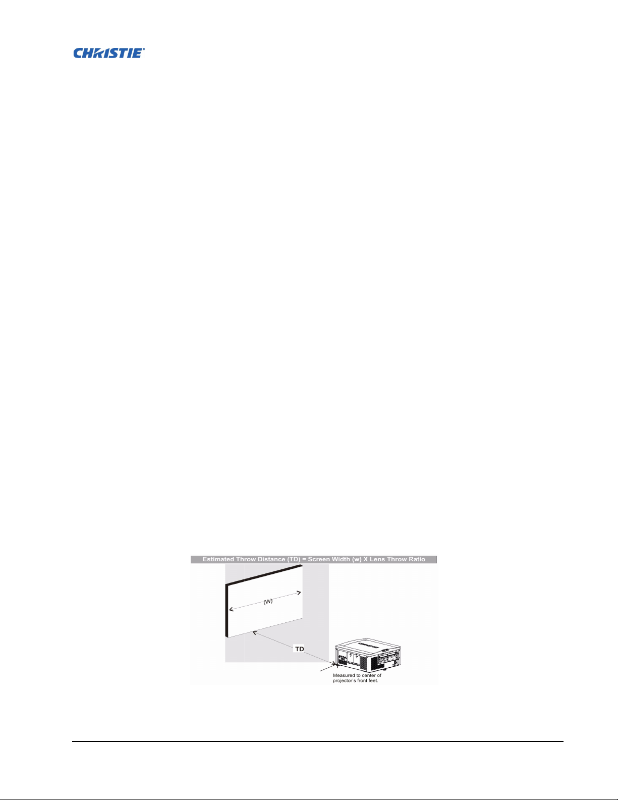
THROW DISTANCE
Throw distance is the distance measured from your projector’s front feet to the screen. This calculation
determines if there is enough room to install your projector with a desired screen size and if the image
will be of the right size for your screen.
To estimate the throw distance take the horizontal width of the screen and multiply it by the lens throw
ratio. The result determines approximately the distance the projector should be positioned from the
screen to project a focused image large enough to fill the screen. For example, using a 0.73:1 lens,
throw distance would roughly be 0.73 x screen width.
IMPORTANT: Use the lens and screen size to calculate the precise throw distance using the tables
provided in the Dealer Section of the Christie Website, PN 020-100221-XX. Due to lens manufactur-
ing tolerances for lens focal length, actual throw distance can vary
±5% between lenses with the same
nominal throw ratio.
FIGURE 2-8 - THROW DISTANCE
M-Series User Manual 2-11
020-100009-01 Rev.1 (07/08)
Section 2: Installation and Setup
VERTICAL AND HORIZONTAL POSITION
The correct vertical and horizontal position of the projector in relation to the screen depends on the
lens type and the screen size. Ideally, the projector should be positioned perpendicular to the screen.
This way, the image will appear rectangular instead of keystoned (trapezoidal).
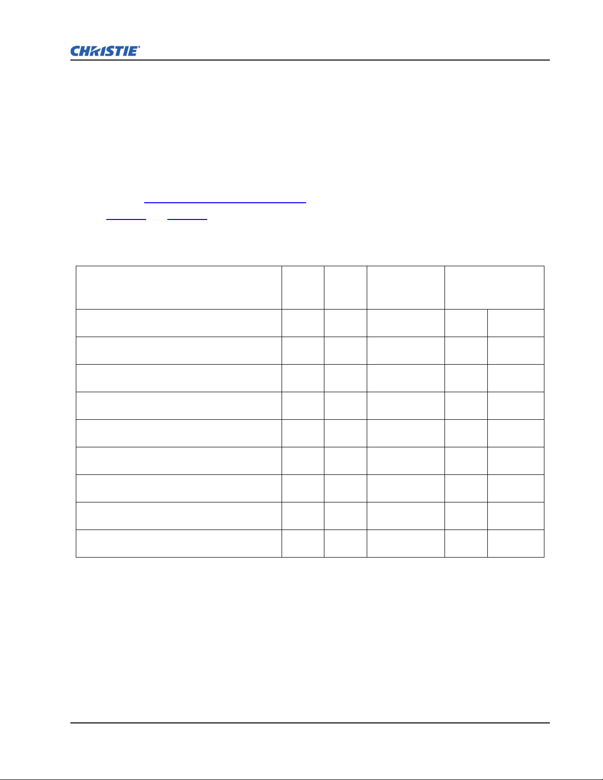
The vertical position of the image can be offset (that is moved above or below the optical axis) by
adjusting the motorized lens mount. The amount of vertical offset available depends on the type of lens
installed in the projector and can be limited if horizontal offset has been applied. Vertical offset can be
expressed as the percent of half the image height or the number of pixels of shift from lens center.
Refer to Figure 2-9 - Vertical Offset Examples
Tab l e 2 .1
and Tab l e 2 .2 specify the vertical offset of each type of lens.
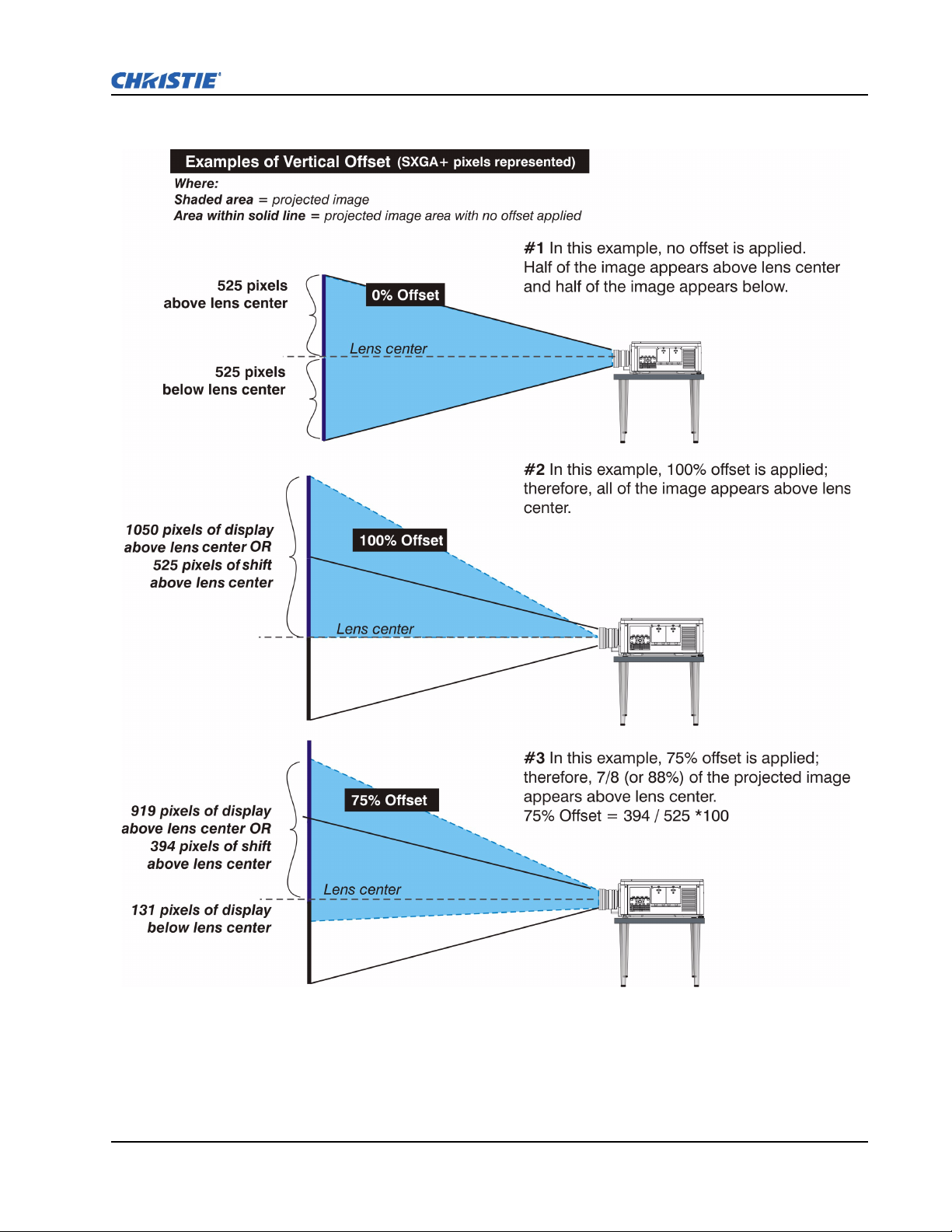
Table 2.1 - Lens Type and Vertical Offsets, HD 1080p (1920 x 1080 pixels)
for illustrated examples of vertical offset.
Lens Throw Ratio Fixed Zoom Lens Part
CHRISTIE ILS LENS 0.73:1 SX+ / 0.67:1 HD 0.95” 3-CHIP
DLP®
CHRISTIE ILS LENS 1.2:1 SX+ / 1.1:1 HD 0.95” 3-CHIP
DLP®
CHRISTIE ILS LENS 1.2:1 SX+ / 1.1:1 HD SFL 0.95” 3-
CHIP DLP®
CHRISTIE ILS LENS 1.25-1.6:1 SX+ / 1.16-1.49:1 HD
0.95” 3-CHIP DLP®
CHRISTIE ILS LENS 1.5-2.0:1 SX+ / 1.4-1.8:1 HD 0.95” 3-
CHIP DLP®
CHRISTIE ILS LENS 2.0-2.8:1 SX+ / 1.8-2.6:1 HD 0.95” 3-
CHIP DLP®
CHRISTIE ILS LENS 2.8-4.5:1 SX+ / 2.6-4.1:1 HD 0.95” 3-
CHIP DLP®
CHRISTIE ILS LENS 4.5-7.5:1 SX+ / 4.1-6.9:1 HD 0.95” 3-
CHIP DLP®
CHRISTIE ILS LENS 7.5-11.2:1 SX+ / 6.9-10.4:1 HD 0.95”
3-CHIP DLP®
Minimum Offset
Number
Above or Below
Lens Center
X 118-100110-XX ±35% ±189 pixels
X 118-100117-XX ±119% ±643 pixels
X 118-101103-XX ±119% ±643 pixels
X 118-100111-XX ±102% ±551 pixels
X 118-100112-XX ±119% ±643 pixels
X 118-100113-XX ±119% ±643 pixels
X 118-100114-XX ±119% ±643 pixels
X 118-100115-XX ±119% ±643 pixels
X 118-100116-XX ±119% ±643 pixels
NOTES: 1) Offsets are subject to ±7% centering tolerance. 2)% Offset = # of pixels of offset/half
vertical panel resolution x 100.
M-Series User Manual 2-12
020-100009-01 Rev.1 (07/08)

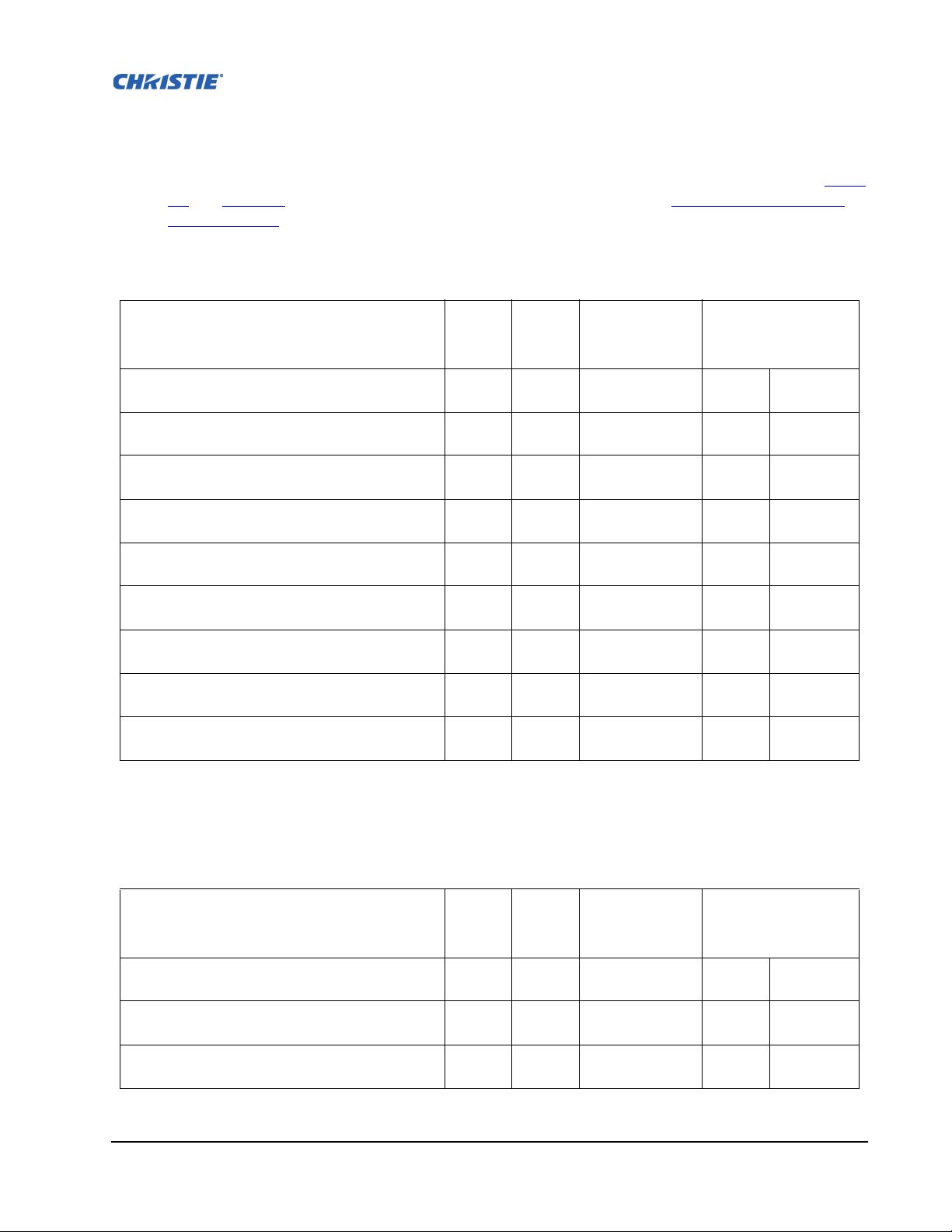
Table 2.2 - Lens Type and Vertical Offsets, SXGA+ (1400 x 105 0 pixels)
Lens Throw Ratio Fixed Zoom Lens Part
CHRISTIE ILS LENS 0.73:1 SX+ / 0.67:1 HD 0.95” 3-CHIP
DLP®
CHRISTIE ILS LENS 1.2:1 SX+ / 1.1:1 HD 0.95” 3-CHIP
DLP®
CHRISTIE ILS LENS 1.2:1 SX+ / 1.1:1 HD SFL 0.95” 3-
CHIP DLP®
CHRISTIE ILS LENS 1.25-1.6:1 SX+ / 1.16-1.49:1 HD
0.95” 3-CHIP DLP®
CHRISTIE ILS LENS 1.5-2.0:1 SX+ / 1.4-1.8:1 HD 0.95” 3-
CHIP DLP®
CHRISTIE ILS LENS 2.0-2.8:1 SX+ / 1.8-2.6:1 HD 0.95” 3-
CHIP DLP®
CHRISTIE ILS LENS 2.8-4.5:1 SX+ / 2.6-4.1:1 HD 0.95” 3-
CHIP DLP®
CHRISTIE ILS LENS 4.5-7.5:1 SX+ / 4.1-6.9:1 HD 0.95” 3-
CHIP DLP®
CHRISTIE ILS LENS 7.5-11.2:1 SX+ / 6.9-10.4:1 HD 0.95”
3-CHIP DLP®
Minimum Offset
Number
Above or Below
Lens Center
X 118-100110-XX ±23% ±121 pixels
X 118-100117-XX ±100% ±525 pixels
X 118-101103-XX ±100% ±525 pixels
X 118-100111-XX ±73% ±383 pixels
X 118-100112-XX ±100% ±525 pixels
X 118-100113-XX ±100% ±525 pixels
X 118-100114-XX ±100% ±525 pixels
X 118-100115-XX ±100% ±525 pixels
X 118-100116-XX ±100% ±525 pixels
NOTES: 1) Offsets are subject to ±7% centering tolerance. 2)% Offset = # of pixels of offset/half
vertical panel resolution x 100.
M-Series User Manual 2-13
020-100009-01 Rev.1 (07/08)
Section 2: Installation and Setup
FIGURE 2-9 - VERTICAL OFFSET EXAMPLES
M-Series User Manual 2-14
020-100009-01 Rev.1 (07/08)
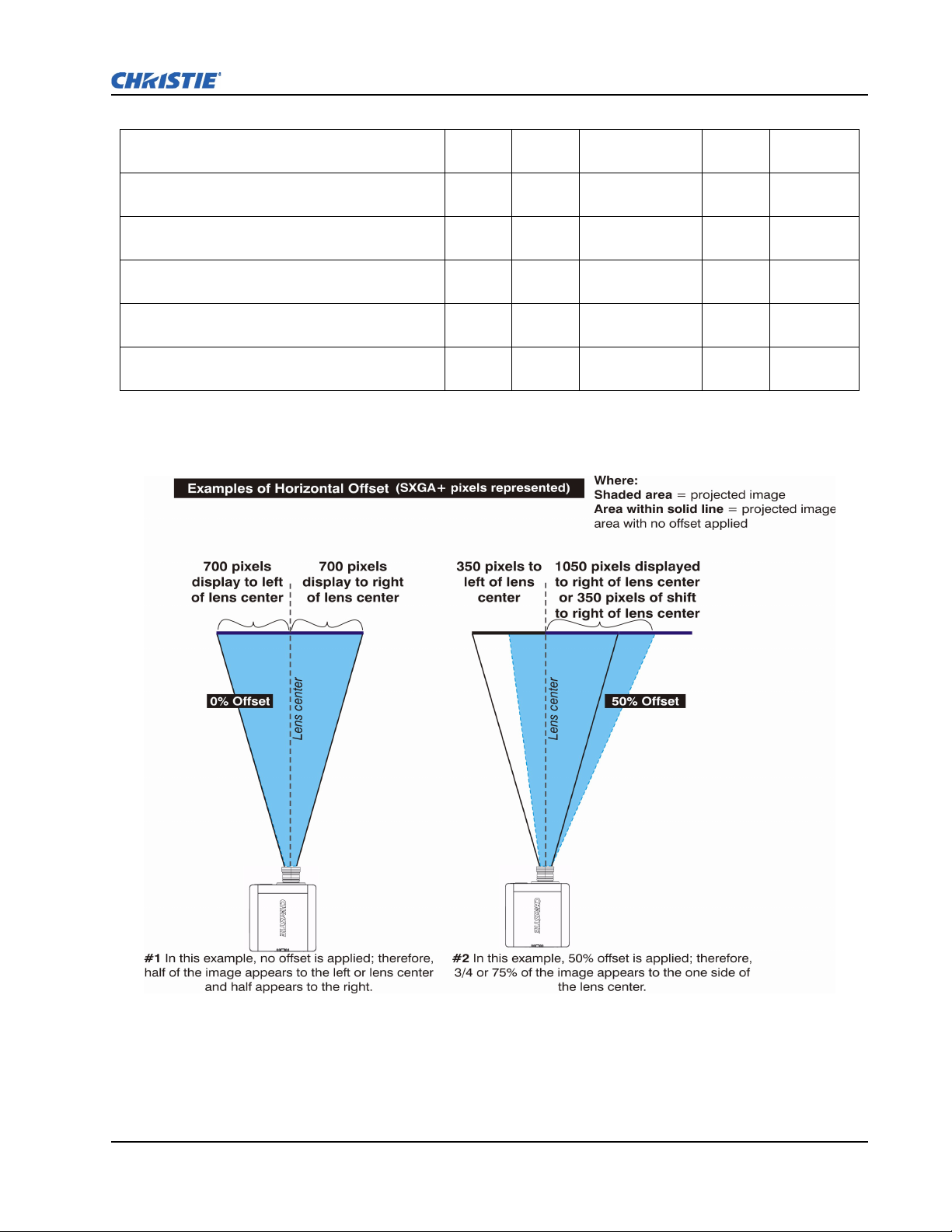
The horizontal position of the image can also be offset; that is moved to the left or right of optical
center, by adjusting the motorized lens mount. The amount of horizontal offset available depends on
the lens installed and if the image has already been vertically offset. Horizontal offset can be expressed
as the percent of half the image width or the number of pixels of shift to one side of lens center. Ta ble
2.3 and Tab l e 2 .4 , each show the horizontal offset of a lens type. Refer to Figure 2-10 - Horizontal
Offset Examples.
Table 2.3 - Lens Type and Horizontal Offsets, HD 1080p (1920 x 1080 pixels)
Lens Throw Ratio Fixed
CHRISTIE ILS LENS 0.73:1 SX+ / 0.67:1 HD 0.95” 3-CHIP
DLP®
CHRISTIE ILS LENS 1.2:1 SX+ / 1.1:1 HD 0.95” 3-CHIP
DLP®
CHRISTIE ILS LENS 1.2:1 SX+ / 1.1:1 HD SFL 0.95” 3-
CHIP DLP®
CHRISTIE ILS LENS 1.25-1.6:1 SX+ / 1.16-1.49:1 HD
0.95” 3-CHIP DLP®
CHRISTIE ILS LENS 1.5-2.0:1 SX+ / 1.4-1.8:1 HD 0.95” 3-
CHIP DLP®
CHRISTIE ILS LENS 2.0-2.8:1 SX+ / 1.8-2.6:1 HD 0.95” 3-
CHIP DLP®
CHRISTIE ILS LENS 2.8-4.5:1 SX+ / 2.6-4.1:1 HD 0.95” 3-
CHIP DLP®
CHRISTIE ILS LENS 4.5-7.5:1 SX+ / 4.1-6.9:1 HD 0.95” 3-
CHIP DLP®
CHRISTIE ILS LENS 7.5-11.2:1 SX+ / 6.9-10.4:1 HD 0.95”
3-CHIP DLP®
Zoom
Lens Part
Number
Minimum Offset
Left or Right of
Lens Center
X 118-100110-XX ±12% ±115 pixels
X 118-100117-XX ±42% ±403 pixels
X 118-101103-XX ±42% ±403 pixels
X 118-100111-XX ±40% ±384 pixels
X 118-100112-XX ±42% ±403 pixels
X 118-100113-XX ±42% ±403 pixels
X 118-100114-XX ±42% ±403 pixels
X 118-100115-XX ±42% ±403 pixels
X 118-100116-XX ±42% ±403 pixels
NOTES: 1) Offsets are subject to ±7% centering tolerance. 2)% Offset = # of pixels of offset/half
horizontal panel resolution x 100.
Table 2.4 - Lens Type and Horizontal Offsets, SXGA+ (1400 x 1050 pixels)
Lens Throw Ratio Fixed
CHRISTIE ILS LENS 0.73:1 SX+ / 0.67:1 HD 0.95” 3-CHIP
DLP®
CHRISTIE ILS LENS 1.2:1 SX+ / 1.1:1 HD 0.95” 3-CHIP
DLP®
CHRISTIE ILS LENS 1.2:1 SX+ / 1.1:1 HD SFL 0.95” 3-
CHIP DLP®
M-Series User Manual 2-15
020-100009-01 Rev.1 (07/08)
X 118-100110-XX ±13% ±91 pixels
X 118-100117-XX ±50% ±350 pixels
X 118-101103-XX ±50% ±350 pixels
Zoom
Lens Part
Number
Minimum Offset
Left or Right of
Lens Center
Section 2: Installation and Setup
CHRISTIE ILS LENS 1.25-1.6:1 SX+ / 1.16-1.49:1 HD
0.95” 3-CHIP DLP®
CHRISTIE ILS LENS 1.5-2.0:1 SX+ / 1.4-1.8:1 HD 0.95” 3-
CHIP DLP®
CHRISTIE ILS LENS 2.0-2.8:1 SX+ / 1.8-2.6:1 HD 0.95” 3-
CHIP DLP®
CHRISTIE ILS LENS 2.8-4.5:1 SX+ / 2.6-4.1:1 HD 0.95” 3-
CHIP DLP®
CHRISTIE ILS LENS 4.5-7.5:1 SX+ / 4.1-6.9:1 HD 0.95” 3-
CHIP DLP®
CHRISTIE ILS LENS 7.5-11.2:1 SX+ / 6.9-10.4:1 HD 0.95”
3-CHIP DLP®
X 118-100111-XX ±45% ±315 pixels
X 118-100112-XX ±50% ±350 pixels
X 118-100113-XX ±50% ±350 pixels
X 118-100114-XX ±50% ±350 pixels
X 118-100115-XX ±50% ±350 pixels
X 118-100116-XX ±50% ±350 pixels
NOTES: 1) Offsets are subject to ±7% centering tolerance. 2)% Offset = # of pixels of offset/half
horizontal panel resolution x 100.
FIGURE 2-10 - HORIZONTAL OFFSET EXAMPLES
M-Series User Manual 2-16
020-100009-01 Rev.1 (07/08)
2.2.4 Mounting
There are several methods for mounting the projector. In typical front and rear screen installations the
projector can be mounted to a secure and level surface, such as a table or cart. Carts are useful when
the projector has to be moved often. Lock the wheels on a cart, when it is in position, to prevent
accidental movement during a presentation.
CEILING MOUNT
The projector can be inverted and suspended from the ceiling using a specially designed ceiling mount
fixture 118-100108-XX. This mounting is recommended for those that want the projector out of plain
view or have limited amount of space for the projector. For more information, contact your dealer.
Use only the CHRISTIE approved ceiling mount kit designed for your
projector. Refer to the installation instructions and safety guidelines provided in
the kit.
SPECIAL MOUNTING
The projector can also be rotated (front-to-back) up to 360 degrees and fixed in a rotated position
without affecting performance. However, the side-to-side tilt limit of the projector must not exceed +/15 degrees, to ensure optimal performance of the projector.
2.2.5 Adjusting Projector Height/Tilt
ADJUSTING HEIGHT
You can modify the height of the projector to remedy a slightly uneven mounting surface by adjusting
the three feet threaded into the bottom chassis. Turn each foot clock-wise or counter-clockwise until
the projector is level on all sides.
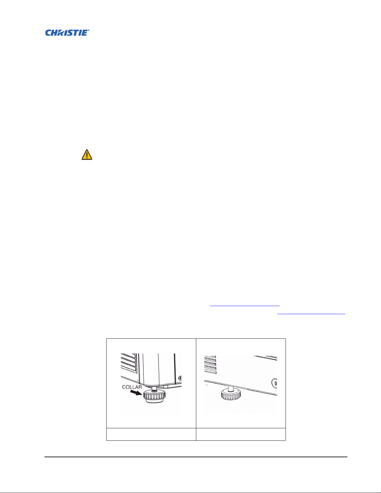
The front feet are adjusted by turning the collar, see Figure 2-11 - Front Foot.
rotate when adjusted. The rear foot is adjusted by turning the entire foot, see Figure 2-12 - Rear Foot.
The front feet do not
IGURE 2-11 - FRONT FOOT FIGURE 2-12 - REAR FOOT
F
M-Series User Manual 2-17
020-100009-01 Rev.1 (07/08)

ADJUSTING TILT
1. Before adjusting tilt, ensure the projector is centered. NOTE: Check with site personnel for the
degree of screen tilt, or measure this incline with a protractor at the screen.
2. Then tilt the projector to closely match the screen tilt angle by extending or retracting the
projector’s 3 adjustable feet.
NOTE: 1) For an ideal installation, the lens surface should be centered and parallel to the screen -
this orientation helps to ensure optimized lens performance with minimal offset. Choose a sturdy
mounting surface that allows for this. If this position is not possible (such as when the projector is
significantly higher than the center of the screen), it is better to rely on offset rather than extra tilt.
2.2.6 Basic Optical Alignment
Only perform image alignment once the projector is fully assembled and powered up in its final
location. Basic image alignment ensures the image reflected from the DMDs is parallel to and wellcentered with the lens and screen. This initial optical alignment is the foundation for optimizing
images on the screen and must be completed before final boresight adjustments. Before beginning
ensure the projector is properly positioned relative to the screen.
Section 2: Installation and Setup
BASIC OPTICAL ALIGNMENT PROCEDURE
1. Display a test pattern: Appropriate for analyzing image focus and geometry, such as the
“framing” test pattern showing the cross-hair centered across the image. Press the (Test) key
Tes t
on the remote keypad or use the built-in keypad and press the soft key that displays Test on the
LCD display.
2. Course focus: Do a quick preliminary focus and (if available) zoom adjustment with the primary
lens. Do not worry about consistency across the image at this point, just center focus. It is good
practice to have zoom adjustment color and focus adjustment color in the center of its range.
3. Center the image in the lens: Holding a piece of paper at the lens surface, adjust offsets as
necessary until the image is centered within the lens perimeter. A full white field works best for
this.
4. If necessary, center the image on the screen: If the projector is mounted off center to the screen
axis, then offset the lens as much as required. Aim the projector over slightly towards the center of
the screen, but use caution when doing so, as too much tilt will cause excessive keystone
distortion. Lens offset will not.
5. Re-check side-to-side leveling: With the framing pattern on screen, double-check projector
leveling so the top edge
of the image is parallel to the top edge of the screen.
6. Throw Distance: Ensure the projector is positioned in the throw distance range for the particular
lens.
FOLDED OPTICS
In rear screen applications where space behind the projector is limited, a mirror may be used to fold the
optical path. The position of the projector and mirror must be accurately set - if considering this type of
installation call your dealer for assistance.
M-Series User Manual 2-18
020-100009-01 Rev.1 (07/08)
Loading...