


USER MANUAL
020-000816-01
CAPTIVA
DUW350S/DHD400S

The CD included with this printed manual contains an electronic copy in English. Please read all instructions before using or servicing this product.
Le DC fourni avec ce manuel imprimé contient une copie électronique en français. S'il vous plaît lire toutes les instructions avant d'utiliser ou de réparer ce produit.
Die mit dieser gedruckten Anleitung gelieferte CD enthält eine elektronische Kopie in Deutsch. Bitte lesen Sie alle Anweisungen, bevor Sie dieses Produkt verwenden oder warten.
Il CD fornito con il manuale stampato contiene una copia elettronica in lingua italiano. Si prega di leggere tutte le istruzioni prima di utilizzare o riparare questo prodotto.
El DC incluido con este manual impreso contiene una copia electrónica en español. Por favor, lea todas las instrucciones antes de usar o dar servicio a este producto.

|
|
|
|
Table of Contents |
|
|
|
||
1. |
Usage Notice......................................................................................................... |
5 |
||
|
1.1 |
COPYRIGHT AND TRADEMARKS.............................................................................. |
5 |
|
|
1.2 |
Safety Information......................................................................................................... |
5 |
|
|
1.3 |
Precautions................................................................................................................... |
7 |
|
2. |
Introduction............................................................................................................ |
9 |
||
|
2.1 |
Package Overview........................................................................................................ |
9 |
|
|
2.2 |
Product Overview.......................................................................................................... |
10 |
|
|
|
2.2.1 |
Main Unit........................................................................................................... |
10 |
|
|
2.2.2 |
Control Panel..................................................................................................... |
11 |
|
|
2.2.3 |
Output Connections........................................................................................... |
12 |
|
|
2.2.4 |
Remote Control................................................................................................. |
13 |
3. |
Installation. |
............................................................................................................ |
14 |
|
|
3.1 |
Connecting the Projector............................................................................................... |
14 |
|
|
|
3.1.1 |
Connect to Computer/Notebook........................................................................ |
14 |
|
|
3.1.2 |
Connect to Video Sources................................................................................. |
15 |
|
3.2 |
Powering the Projector On/Off...................................................................................... |
16 |
|
|
|
3.2.1 |
Powering On the Projector................................................................................ |
16 |
|
|
3.2.2 |
Powering off the projector.................................................................................. |
17 |
|
|
3.2.3 |
Warning Indicator.............................................................................................. |
17 |
|
3.3 |
Adjusting the Projected Image...................................................................................... |
18 |
|
|
|
3.3.1 |
Adjusting the Projector s Height........................................................................ |
18 |
|
|
3.3.2 |
Adjusting the Projector s Focus......................................................................... |
19 |
|
|
3.3.3 |
Adjusting Projection Image Size (Diagonal)...................................................... |
20 |
4. |
User Controls......................................................................................................... |
22 |
||
|
4.1 |
Control Panel & Remote Control................................................................................... |
22 |
|
|
|
4.1.1 |
Control Panel..................................................................................................... |
22 |
|
|
4.1.2 |
Remote Control................................................................................................. |
23 |
|
4.2 |
On-screen Display Menus............................................................................................. |
25 |
|
|
|
4.2.1 |
How to operate.................................................................................................. |
25 |
|
|
4.2.2 |
Image................................................................................................................. |
26 |
|
|
4.2.3 |
Configuration..................................................................................................... |
28 |
|
|
4.2.4 |
Settings.............................................................................................................. |
30 |
|
|
4.2.5 |
Audio................................................................................................................. |
32 |
|
|
4.2.6 |
Options.............................................................................................................. |
33 |
|
|
4.2.7 |
Options | Laser Settings.................................................................................... |
35 |
|
|
4.2.8 |
3D...................................................................................................................... |
36 |
|
|
4.2.9 |
Interactive.......................................................................................................... |
37 |
|
|
4.2.10 LAN.................................................................................................................... |
38 |
|
5. |
Multimedia............................................................................................................. |
|
44 |
|
|
5.1 |
Accessing Multimedia Files........................................................................................... |
44 |
|
|
|
5.1.1 How to access Multimedia mode....................................................................... |
44 |
|
6. |
Appendices............................................................................................................ |
51 |
||
|
6.1 |
Installing and Cleaning the Optional Dust Filter............................................................ |
51 |
|
|
6.2 |
Compatibility Modes...................................................................................................... |
52 |
|
|
|
6.2.1 |
VGA Analog....................................................................................................... |
52 |
|
|
6.2.2 |
HDMI Digital...................................................................................................... |
54 |
|
6.3 |
RS232 Commands and Protocol Function List............................................................. |
56 |
|
|
|
6.3.1 |
RS232 Port Setting............................................................................................ |
56 |
|
|
|||
CAPTIVA DUW350S/CAPTIVA DHD400S User Manual |
3 |
|||
020-000816-01 Rev. 1 (07-2015)

Table of Contents
|
6.3.2 |
RS232 Signals Connection................................................................................ |
56 |
|
6.3.3 |
Commands Set List........................................................................................... |
57 |
6.4 |
Regulation & Safety Notices......................................................................................... |
60 |
|
6.5 |
Ceiling Mount Installation.............................................................................................. |
63 |
|
4 |
CAPTIVA DUW350S/CAPTIVA DHD400S User Manual |
020-000816-01 Rev. 1 (07-2015)

Section 1: Usage Notice
111 Usage Notice
1.1COPYRIGHT AND TRADEMARKS
Copyright ©2015 Christie Digital Systems USA, Inc. All rights reserved.
All brand names and product names are trademarks, registered trademarks or trade names of their respective holders.
1.2Safety Information
The lightning flash with arrow head within an equilateral triangle is intended to alert the user to the presence of uninsulated “dangerous voltage” within the product’s enclosure that may be of sufficient magnitude to constitute a risk of electric shock to persons.
The exclamation point within an equilateral triangle is intended to alert the user to the presence of important operating and maintenance (servicing) instructions in the literature accompanying the projector.
WARNING: TO REDUCE THE RISK OF FIRE OR ELECTRIC SHOCK, DO NOT EXPOSE THIS PROJECTOR TO RAIN OR MOISTURE. DANGEROUS HIGH VOLTAGES ARE PRESENT INSIDE THE ENCLOSURE. DO NOT OPEN THE CABINET. REFER SERVICING TO QUALIFIED PERSONNEL ONLY.
Class B emissions limits
This Class B digital apparatus meets all requirements of the Canadian InterferenceCausing Equipment Regulations.
Important Safety Instruction
111 Do not block any ventilation openings. To ensure reliable operation of the projector and to protect from over heating, it is recommended to install the projector in a location that does not block ventilation. As an example, do not place the projector on a crowded coffee table, sofa, bed and so on. Do not put the projector in an enclosure such as a bookcase or a cabinet that restricts air flow.
222 Do not use the projector near water or moisture. To reduce the risk of fire and/or electric shock, do not expose the projector to rain or moisture.
333 Do not install near heat sources such as radiators, heaters, stoves or any other apparatus such as amplifiers that emits heat.
444 Clean only with dry cloth.
555 Only use attachments/accessories specified by the manufacturer.
666 Do not use the unit if it has been physically damaged or abused. Physical damage/abuse would be (but not limited to):
-- Unit has been dropped.
-- Power supply cord or plug has been damaged. -- Liquid has been spilled on to the projector.
-- Projector has been exposed to rain or moisture.
-- Something has fallen in the projector or something is loose inside.
Do not attempt to service the unit yourself. Opening or removing covers may expose you to dangerous voltages or other hazards.
CAPTIVA DUW350S/CAPTIVA DHD400S User Manual |
5 |
020-000816-01 Rev. 1 (07-2015)

Section 1: Usage Notice
777 Do not let objects or liquids enter the projector. They may touch dangerous voltage points and short out parts that could result in fire or electric shock.
888 See projector enclosure for safety related markings.
999 The unit should only be repaired by appropriate service personnel.
6 |
CAPTIVA DUW350S/CAPTIVA DHD400S User Manual |
020-000816-01 Rev. 1 (07-2015)

Section 1: Usage Notice
1.3Precautions
Follow all warnings, precautions and maintenance as recommended in this user’s guide.
 WARNING
yy Do not look into the projector’s lens when the lamp is on. The bright light may hurt and damage your eyes.
yy To reduce the risk of fire or electric shock, do not expose this projector to rain or moisture.
yy Do not open or disassemble the projector as this may cause electric shock.
CAPTIVA DUW350S/CAPTIVA DHD400S User Manual |
7 |
020-000816-01 Rev. 1 (07-2015)

Section 1: Usage Notice
Do:
yy Turn off and unplug the power plug from the AC outlet before cleaning the product.
yy Use a soft dry cloth with mild detergent to clean the display housing.
yy Disconnect the power plug from AC outlet if the product is not being used for a long period of time.
yy Use a plat beneath the projector while portrait orientation to meet safety requirement.
Do not:
yy Block the slots and openings on the unit provided for ventilation. yy Use abrasive cleaners, waxes or solvents to clean the unit.
yy Use under the following conditions:
-- In extremely hot, cold or humid environments.
`` Sea level to 6000 feet Extremely hot: > 35°C Extremely cool: < 5°C
`` 6000 feet above Extremely hot: > 30°C Extremely cool: < 5°C
`` Extremely humid: > 70% R.H. (Relative Humidity) -- In areas susceptible to excessive dust and dirt.
-- Near any appliance generating a strong magnetic field. -- In direct sunlight.
8 |
CAPTIVA DUW350S/CAPTIVA DHD400S User Manual |
020-000816-01 Rev. 1 (07-2015)

Section 2: Introduction
222 Introduction
2.1Package Overview
Unpack and inspect the box contents to ensure all parts listed below are in the box. If something is missing, contact your customer service center.
Projector |
Power Cord |
VGA Cable |
Documentation :
User’s Manual & Quick Start Guide
NOTE:
Due to different applications in each country, some regions may have different accessories.
CAPTIVA DUW350S/CAPTIVA DHD400S User Manual |
9 |
020-000816-01 Rev. 1 (07-2015)

Section 2: Introduction
2.2Product Overview
2.2.1 Main Unit
5 |
1 |
|
2
3
4
9
8
6
7
Ind. |
Part Name |
Ind. |
Part Name |
|
|
|
|
1 |
Control Panel |
6 |
Speaker |
|
|
|
|
2 |
Focus switch |
7 |
Power Socket |
|
|
|
|
3 |
Ventilation (inlet) |
8 |
Input/Output Connections |
|
|
|
|
4 |
IR Receiver |
9 |
Lens |
|
|
|
|
5 |
Ventilation (outlet) |
|
|
|
|
|
|
|
NOTE: |
|
The interface is subject to model’s specifications. |
10 |
CAPTIVA DUW350S/CAPTIVA DHD400S User Manual |
020-000816-01 Rev. 1 (07-2015)
Section 2: Introduction
2.2.2Control Panel
8
1 |
2 |
3 |
4 |
|
|
|
5 |
|
|
|
6 |
9
7
Ind. |
Part Name |
1Power LED
2Enter
3Temp LED
4Lamp LED
5Menu
6Input
7Four Directional Select keys
8Power/Standby button
9IR Receiver
CAPTIVA DUW350S/CAPTIVA DHD400S User Manual |
11 |
020-000816-01 Rev. 1 (07-2015)

Section 2: Introduction
2.2.3Output Connections
|
|
1 |
2 |
3 |
4 |
5 |
6 |
7 |
|
8 |
9 |
10 1112 13 14 |
15 16 17 |
|
|||
Ind. |
|
|
Connector Name |
|
Ind. |
Connector Name |
||
|
VGA1-In/YPbPr Connector |
|
|
|
||||
1 |
(PC Analog Signal/Component |
10 |
RS-232 Connector (9-pin DCE type) |
|||||
|
Video Input/HDTV/YPbPr) |
|
|
|
||||
2 |
HDMI2 Input Connector |
11 |
Composite Video Input Connector |
|
|
|
|
|
|
3 |
HDMI1 Input Connector |
12 |
Composite Audio Input (right) |
|
|
|
|
Connector |
|
4 |
USB Connector (Connect PC for |
13 |
Composite Audio Input (left) |
|
firmware upgrade or interactive) |
Connector |
|||
5 |
RJ45 connector |
14 |
Audio Output Connector (3.5mm |
|
mini jack) |
||||
6 |
USB Type A Connector |
15 |
Audio Input Connector (3.5mm mini |
|
jack) |
||||
7 |
Power Socket |
16 |
Audio Input Connector (microphone) |
|
|
|
|
|
|
8 |
Interactive Connector (3.5 mm mini |
17 |
KensingtonTM Lock Port |
|
jack) |
||||
|
|
|
||
9 |
VGA-Out/VGA2-In Connector |
|
|
NOTE:
Monitor loop through only support in VGA1-In/YPbPr.
12 |
CAPTIVA DUW350S/CAPTIVA DHD400S User Manual |
020-000816-01 Rev. 1 (07-2015)

Section 2: Introduction
2.2.4Remote Control
1
2 |
|
|
3 |
|
4 |
5 |
|
6 |
7 |
9 |
8 |
10 |
11 |
14 |
12 |
|
|
15 |
13 |
16 |
17 |
18 |
19 |
20 |
21 |
23 22
Ind. |
Part Name |
1Infrared transmitter
2LED Indicator
3Power On/Off
4Enter
5Four Directional Select keys
6Menu
7Exit
8Zoom in
9Reset
10Auto
11Input
12Zoom out
13Volume +/-
14Keystone +/-
15Image
16Picture mute
17Aspect ratio
18VGA1
19HDMI1
20VGA2
21HDMI2
22Video
23Screen freeze
CAPTIVA DUW350S/CAPTIVA DHD400S User Manual |
13 |
020-000816-01 Rev. 1 (07-2015)
Section 3: Installation
333 Installation
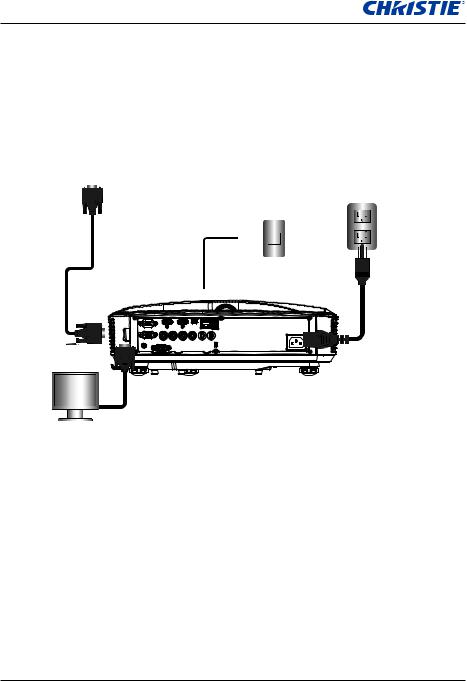
3.1Connecting the Projector
3.1.1 Connect to Computer/Notebook
Router/Network switch
5
1
|
|
10 |
|
Microphone |
|
|
|
|
|
External |
9 |
|
|
|
|
|
|
||
Display |
|
|
|
|
|
|
Audio Output |
|
|
Ind. |
Connector Name |
Ind. |
Connector Name |
|
1 |
RS232 Cable |
7 |
Power Cord |
|
2 |
VGA Cable |
|
8 |
VGA Output Cable |
3 |
HDMI Cable |
|
9 |
DC to DC Cable |
4 |
USB Cable |
|
10 |
Audio Output Cable |
5 |
Audio Cable/RCA |
11 |
Audio Input Cable |
|
6 |
RJ45 Cable |
|
|
|
14 |
|
CAPTIVA DUW350S/CAPTIVA DHD400S User Manual |
||
020-000816-01 Rev. 1 (07-2015)
Section 3: Installation
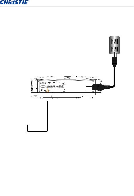
3.1.2Connect to Video Sources
DVD Player, Set-top Box,
HDTV receiver
1 |
2 |
|
4 |
|
|
3 |
|
|
|
|
5


 E62405SP R


Composite Video Output
8
|
|
|
|
Microphone |
|
6 |
7 |
|
|
|
|
|
|
|
|
|
|
|
Audio Output |
|
|
|
|
|
Ind. |
Connector Name |
Ind. |
Connector Name |
|
1 |
15-Pin to 3 RCA Component/HDTV |
5 |
Power Cord |
|
Adaptor |
|
|||
|
|
|
|
|
2 |
HDMI Cable |
|
6 |
Composite Video Cable |
|
|
|
|
|
3 |
Audio Cable |
|
7 |
Audio Cable/RCA |
|
|
|
|
|
4 |
Audio Cable/RCA |
|
8 |
Audio Input Cable |
|
|
|
|
|
CAPTIVA DUW350S/CAPTIVA DHD400S User Manual |
15 |
020-000816-01 Rev. 1 (07-2015)

Section 3: Installation
3.2Powering the Projector On/Off
3.2.1 Powering On the Projector
111Securely connect the power cord and signal cable. When connected, the POWER/STANDBY LED turns Orange.
222Turn on the projector by pressing “ ” button either on the projector or on the remote. At this moment, the POWER/STANDBY LED turns Blue.
333The startup screen will display in approximately 5 seconds. The first time you use the projector, you will be asked to select the preferred language and power saving mode.
444Turn on and connect the source that you want to display on the screen (computer, notebook, video player, etc). The projector detects the source automatically. If not, push menu button and go to “OPTIONS”.
Make sure that the “Source Lock” has been set to “Off”.
NOTE:
If you connect multiple sources at the same time, press the “INPUT” button on the control panel or direct source keys on the remote control to switch between inputs.
When the power mode is in standby mode (power consumption < 0.5W), the VGA output/input and audio are deactivated when the projector is in standby.
1 POWER/STANDBY
|
|
|
|
|
|
|
|
|
|
|
|
|
|
|
|
|
|
|
|
|
|
|
|
16 |
CAPTIVA DUW350S/CAPTIVA DHD400S User Manual |
||||
020-000816-01 Rev. 1 (07-2015)

Section 3: Installation
3.2.2Powering off the projector
111Press the “ ” button on the remote control or on the control panel to turn off the projector. The following message will be displayed on the screen.
Press power key again to confirm
Press the “ ” button again to confirm otherwise the message will disappear after 10 seconds. When you press the “ ” button for the second time, the fan will start cooling the system and will shut down.
222The cooling fans continue to operate for about four seconds for cooling cycle and the POWER/STANDBY LED will flash Orange.
When the POWER/STANDBY LED lights solid Orange, the projector has entered standby mode.
If you want to turn the projector back on, you must wait until the projector has completed the cooling cycle and has entered standby mode. Once in standby mode, press “ ” button to restart the projector.
333Disconnect the power cord from the electrical outlet and the projector.
3.2.3Warning Indicator
When the warning indicators (see below) come on, the projector will automatically shutdown:
yy “LAMP” LED indicator is lit red and if “POWER/STANDBY” indicator flashes amber.
yy “TEMP” LED indicator is lit red, this indicates the projector has overheated. Under normal conditions, the projector can be switched back on.
yy “TEMP” LED indicator flashes red and if “POWER/STANDBY” indicator flashes amber.
Unplug the power cord from the projector, wait for 30 seconds and try again. If the warning indicator light up again, contact your service center for assistance.
CAPTIVA DUW350S/CAPTIVA DHD400S User Manual |
17 |
020-000816-01 Rev. 1 (07-2015)
Section 3: Installation
3.3Adjusting the Projected Image
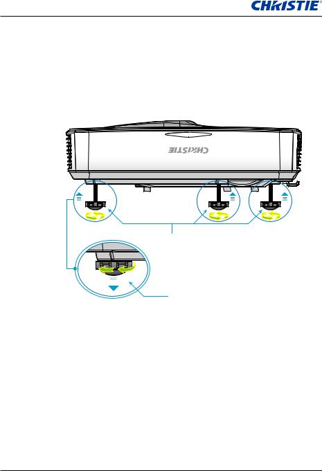
3.3.1Adjusting the Projector s Height
The projector is equipped with elevator feet for adjusting the image height.
111Locate the adjustable foot you want to modify on the underside of the projector.
222Rotate the adjustable ring clockwise to raise the projector or counter clockwise to lower it. Repeat with the remaining feet as needed.
Tilt-Adjustment Feet
Tilt-Adjustment Ring
18 |
CAPTIVA DUW350S/CAPTIVA DHD400S User Manual |
020-000816-01 Rev. 1 (07-2015)

Section 3: Installation
3.3.2Adjusting the Projector s Focus
To focus the image, slide the focus switch to left/right until the image is clear.
yy 1080p series: The projector will focus at distances from 1.443 to 1.887 feet (0.437 to 0.572 meters).
yy Ultra Wide series: The projector will focus at distances from 1.413 to 1.884 feet (0.428 to 0.571 meters).
Focus switch |
CAPTIVA DUW350S/CAPTIVA DHD400S User Manual |
19 |
020-000816-01 Rev. 1 (07-2015)

Section 3: Installation
3.3.3Adjusting Projection Image Size (Diagonal)
yy 1080p series: Projection Image Size from 80” to 100” (2.03 to 2.54 meters).
yy Ultra Wide series: Projection Image Size from 120” to 140” (3.05 to 3.56 meters).
Top View
Projection Distance (D)
Side View
Screen
Screen (W)
|
|
|
|
|
|
|
|
Height |
|
|
|
||||||
|
|
|
||||||
|
|
|
|
|
|
|
|
|
|
|
|
|
|
|
|
|
|
|
|
|
|
|
|
|
|
|
Screen |
|
|
|
Screen (H) |
||||
|
|
|
|
|
|
|
|
|
|
|
|
|
|
|
|
|
|
|
|
|
|
|
|
|
|
|
|
|
|
|
|
|
|
|
|
|
|
|
|
|
|
Offset (Hd) |
||
Diagonal
Wide
Projection Distance (D)
DHD400S
Diagonal length |
|
Screen Size W x H |
|
|
Projection Distance (D) |
|
Offset (Hd) |
|||||
(inch) size of |
(mm) |
(inch) |
(mm) |
(inch) |
|
|||||||
|
|
|
||||||||||
16:9 Screen |
Width |
Height |
Width |
Height |
wide |
|
tele |
wide |
|
tele |
(mm) |
(inch) |
|
|
|
||||||||||
87 |
192.6 |
108.3 |
75.8 |
42.6 |
23.3 |
|
NA |
9.2 |
|
NA |
28.9 |
11.4 |
90 |
199.2 |
112.1 |
78.4 |
44.1 |
24.9 |
|
NA |
9.8 |
|
NA |
29.6 |
11.7 |
95 |
210.3 |
118.3 |
82.8 |
46.6 |
27.7 |
|
NA |
10.9 |
|
NA |
30.9 |
12.2 |
100 |
221.4 |
124.5 |
87.2 |
49.0 |
30.5 |
|
NA |
12.0 |
|
NA |
32.2 |
12.7 |
102 |
225.8 |
127.0 |
88.9 |
50.0 |
31.6 |
|
NA |
12.4 |
|
NA |
32.7 |
12.9 |
20 |
CAPTIVA DUW350S/CAPTIVA DHD400S User Manual |
020-000816-01 Rev. 1 (07-2015)
 Loading...