

Page 1
CATEYE STRADA
START
CC-RD100N
Quick Start
Click the button and follow the instructions.
Page 2
Thank you for purchasing our cyclocomputer CATEYE STRADA.
Next
This Quick Start Manual explains how to set up the computer and how to install the unit on
your bicycle.
Please set up the unit according to the specified procedure, then it will be ready for use as a
cyclocomputer.
Before use, read the instruction manual that comes with the product thoroughly
to the end to understand the functions of this unit, and to use it safely in a
correct manner.
Page 3

This PDF contains a movie file.
Next
When you click on the movie screen, a message regarding security appears. Click the
“Trust in the text” or “Play” button to close the message.
Click the screen again to play the movie.
Page 4

CATEYE STRADA
Return to Cover
Setting up the computer
How to install the speed sensor
How to install the bracket (movie)
Quick Start Manual
Click the item you wish to view.
Contents
Page 5
Operation of buttons
MODE
MENU
Next
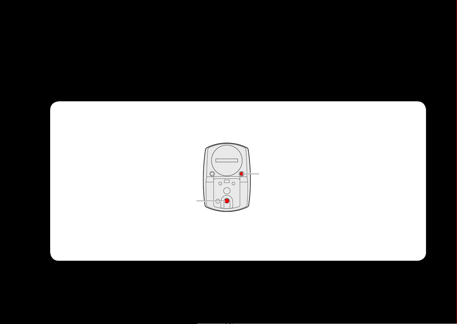
Set up the computer by operating the buttons as follows.
Check the button position before you start setting up.
Back
Press the MENU button and the MODE
button on the back of the computer.
Page 6
CATEYE STRADA
ACAC
Return to Contents
Next
Return
Quick Start Manual
Clear all data (initialization)
Setting the speed unit
Entering the tire
circumference
Setting the clock display
Setting the hour
Setting up the computer
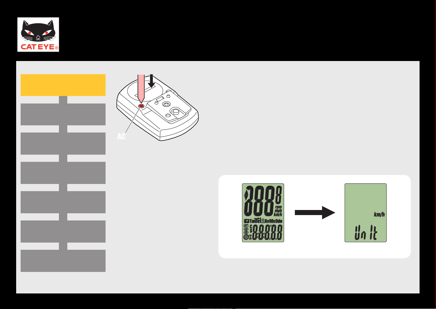
Clear all data (initialization)
Press the AC button on the back of the computer.
After full lighting of the screen, the computer switch-
es to the speed unit setting screen to start setup.
Setting the minute
Measuring screen
(Setup completed)
Full lighting Setting the speed unit
Page 7
CATEYE STRADA
MENU
MODE
Return to Contents
Next
Return
Quick Start Manual
Clear all data (initialization)
Setting the speed unit
Entering the tire
circumference
Setting the clock display
Setting the hour
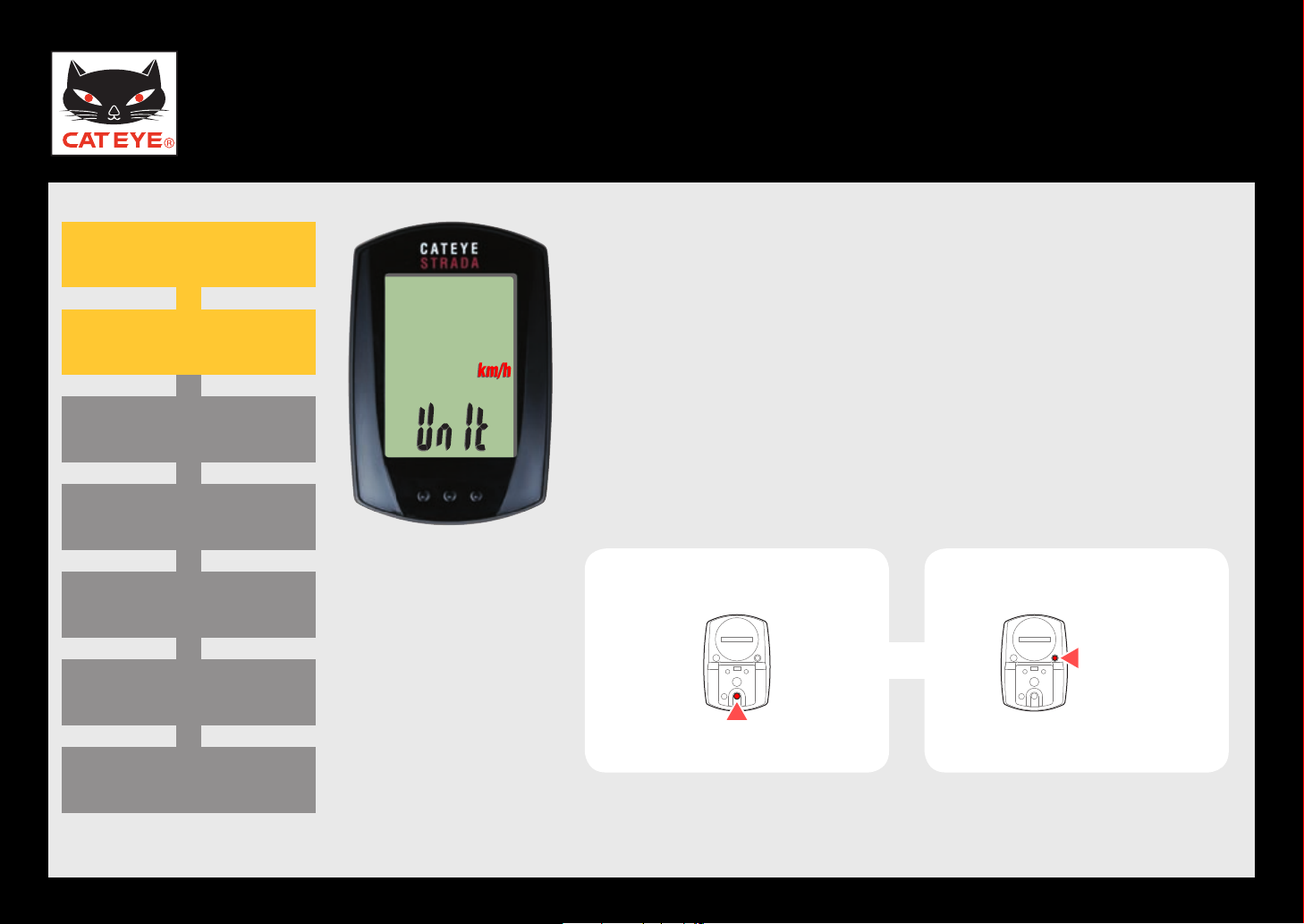
Setting the speed unit
Setting up the computer
Setting the speed unit
When the MODE button is pressed, either “km/h” or “mph”
is selected for the speed unit display. Select the display of
your choice.
After selecting, press the MENU button to proceed to the
next step “Entering the tire circumference”.
km/h ↔ mph
To the next step
Setting the minute
Measuring screen
(Setup completed)
Page 8

CATEYE STRADA
MENU
MODE
MODE
Return to Contents
Next
Return
Tire circum-
ference refer-
ence table
Quick Start Manual
Clear all data (initialization)
Setting the speed unit
Entering the tire
circumference
Setting the clock display
Setting the hour
Entering the tire
circumference
Setting up the computer
Entering the tire circumference
Enter the tire circumference (mm) of your bicycle with
4 digits using the tire circumference reference table.
Pressing the MODE button increases the value flashing, and
pressing and holding the MODE button moves to the next digit.
After entering, press the MENU button to proceed to the
next step “Setting the clock display.
Move digitIncrease the value
To the next step
Setting the minute
(Setup completed)
Measuring screen
(Press and hold)
Page 9

CATEYE STRADA
MODE
MODE
Return to Contents
Next
Return
Quick Start Manual
Clear all data (initialization)
Setting the speed unit
Entering the tire
circumference
Setting the clock display
Setting the hour
Clock display
Setting up the computer
Setting the clock display
When you press and hold the MODE button, “24h” flashes.
When the MODE button is pressed, either “12h” or “24h”
is selected for the clock display. Select the display of your
choice.
After selecting, press and hold the MODE button to proceed to the next step “Setting the hour”.
24h ↔ 12h
To the next step
Setting the minute
Measuring screen
(Setup completed)
(Press and hold)
Page 10

CATEYE STRADA
MODE
MODE
Return to Contents
Next
Return
Quick Start Manual
Clear all data (initialization)
Setting the speed unit
Entering the tire
circumference
Setting the clock display
Setting the hour
Hour
Setting up the computer
Setting the hour
Pressing the MODE button increases the value flashing
(“Hour” of the clock). Enter any value.
After entering, press and hold the MODE button to proceed to the next step “Setting the minute”.
Increase the value
To the next step
Setting the minute
Measuring screen
(Setup completed)
(Press and hold)
Page 11

CATEYE STRADA
MENU
MODE
Return to Contents
Next
Return
Quick Start Manual
Clear all data (initialization)
Setting the speed unit
Entering the tire
circumference
Setting the clock display
Setting the hour
Minute
Setting up the computer
Setting the minute
Pressing the MODE button increases the value flashing
(“Minute” of the clock). Enter any value (Pressing and
holding MODE rapidly increases the value).
After entering, press the MENU button to switch to the
measuring screen.
Increase the value
Setup is completed
To the measuring screen
Setting the minute
Measuring screen
(Setup completed)
Page 12

CATEYE STRADA
Return to Contents
Next
Return
Return to Contents
Quick Start Manual
Clear all data (initialization)
Setting the speed unit
Entering the tire
circumference
Setting the clock display
Setting the hour
Setting up the computer
Now, setup of the computer is completed.
If the bracket and speed sensor are not installed on your
bicycle, return to Contents, click “How to install the bracket” and “How to install the speed sensor”, and then install
them according to the instructions.
Measuring screen
Setting the minute
Measuring screen
(Setup completed)
Page 13

CATEYE STRADA
Return to Contents
Quick Start Manual
How to install the bracket
The Bracket being used in this movie is for wireless products and • there is no wire attached.
When you install the bracket band to your bicycle, tighten it so the wire will not be pinched by the stem •
or handlebar.
Page 14

Prepare the following parts from the packaged items.
Next
Hook
Sensor rubber pad (x2) Sensor rubber pad (x3)
Speed sensor
Magnet
Nylon ties (x5)
Page 15

CATEYE STRADA
Return to Contents
Next
Return
Quick Start Manual
Install the speed sensor
Install the magnet
Adjust the positions of the
speed sensor and magnet
Adjust the clearance between
the speed sensor and magnet
Fixing the wire
How to install the speed sensor
Install the speed sensor
Select the suitable size for the front fork diameter of
your bicycle from two different sensor rubber bands.
1
Attach the sensor hook to the sensor rubber band,
and install it to the right front fork of your bicycle.
2
Pass the speed sensor through the sensor rubber band
installed. Install the sensor rubber band so that it fits
in the hook on the top and bottom of the sensor.
You may use nylon ties instead of the sensor rub-*
ber band.
Right front fork
Speed sensor
Winding the wire
(Installation is completed)
Hook
Rubber band
Page 16

CATEYE STRADA
Return to Contents
Next
Return
Quick Start Manual
Install the speed sensor
Install the magnet
Adjust the positions of the
speed sensor and magnet
Adjust the clearance between
the speed sensor and magnet
Fixing the wire
How to install the speed sensor
Install the magnet
Temporarily secure the magnet to the right side
spoke of the front wheel spoke.
Tighten the magnet to such an extent that it can be
moved.
Right side spoke
Magnet
To the SENSOR ZONE
Winding the wire
(Installation is completed)
Page 17

CATEYE STRADA
Return to Contents
Next
Return
Quick Start Manual
Install the speed sensor
Install the magnet
Adjust the positions of the
speed sensor and magnet
Adjust the clearance between
the speed sensor and magnet
Fixing the wire
How to install the speed sensor
Adjust the positions of the speed sensor
and magnet
Adjust the position so that the magnet passes
through the SENSOR LINE of the speed sensor.
After adjusting, tighten firmly the magnet.
Magnet
SENSOR LINE
Winding the wire
(Installation is completed)
Speed sensor
(inside the front fork)
Page 18

CATEYE STRADA
5 mm 5 mm
or
Return to Contents
Next
Return
Quick Start Manual
Install the speed sensor
Install the magnet
Adjust the positions of the
speed sensor and magnet
Adjust the clearance between
the speed sensor and magnet
Fixing the wire
How to install the speed sensor
Adjust the clearance between the speed
sensor and magnet
Adjust the clearance between the speed sensor and
magnet so that it is within 5 mm.
When the clearance with the magnet is more than
5 mm, install the speed sensor with 1 to 3 sensor
rubber pads in layers.
Speed sensor
Magnet
Winding the wire
(Installation is completed)
Sensor rubber pad
(1 to 3 sheets)
Page 19

CATEYE STRADA
Return to Contents
Next
Return
Quick Start Manual
Install the speed sensor
Install the magnet
Adjust the positions of the
speed sensor and magnet
Adjust the clearance between
the speed sensor and magnet
Fixing the wire
How to install the speed sensor
Fixing the wire
Fix the wire to the front fork with nylon ties. Cut off
any excess nylon tie using a nipper.
Nylon ties
Pull securely
Winding the wire
(Installation is completed)
Page 20

CATEYE STRADA
Return to Contents
Next
Return
Return to Contents
Quick Start Manual
Install the speed sensor
Install the magnet
Adjust the positions of the
speed sensor and magnet
Adjust the clearance between
the speed sensor and magnet
Fixing the wire
How to install the speed sensor
Winding the wire
Wind the wire around the brake cable.
Caution: Adjust this
not stretched when you turn the handle.
Now, speed sensor installation is completed.
See how to install the bracket, and then complete
the installation.
When the computer is not set up, return to Contents, click “Setting up the computer”, and follow
the instructions.
section so that the wire is
Winding the wire
(Installation is completed)
Page 21

CATEYE STRADA
L mm
Return to Contents
Return
Quick Start Manual
Tire circumference reference table
ETRTO
Tire size
47-203 12x1.75 935
54-203 12x1.95 940
40-254 14x1.50 1020
47-254 14x1.75 1055
40-305 16x1.50 1185
47-305 16x1.75 1195
54-305 16x2.00 1245
28-349 16x1-1/8 1290
37-349 16x1-3/8 1300
32-369 17x1-1/4 (369) 1340
40-355 18x1.50 1340
47-355 18x1.75 1350
32-406 20x1.25 1450
35-406 20x1.35 1460
Measure the tire circumference (L) of your bicycle
L (mm)
ETRTO
Tire size
40-406 20x1.50 1490
47-406 20X1.75 1515
50-406 20x1.95 1565
28-451 20x1-1/8 1545
37-451 20x1-3/8 1615
37-501 22x1-3/8 1770
40-501 22x1-1/2 1785
47-507 24x1.75 1890
50-507 24x2.00 1925
54-507 24x2.125 1965
25-520 24x1 (520) 1753
24x3/4 Tubular 1785
28-540 24x1-1/8 1795
32-540 24x1-1/4 1905
L (mm)
ETRTO
Tire size
25-559 26x1 (559) 1913
32-559 26x1.25 1950
37-559 26x1.40 2005
40-559 26x1.50 2010
47-559 26x1.75 2023
50-559 26x1.95 2050
54-559 26x2.10 2068
57-559 26x2.125 2070
58-559 26x2.35 2083
75-559 26x3.00 2170
28-590 26x1-1/8 1970
37-590 26x1-3/8 2068
37-584 26x1-1/2 2100
650C Tubular 26x7/8 1920
L (mm)
Setting up the computer
ETRTO
Tire size
20-571 650x20C 1938
23-571 650x23C 1944
25-571 650x25C 26x1 (571) 1952
40-590 650x38A 2125
40-584 650x38B 2105
25-630 27x1 (630) 2145
28-630 27x1-1/8 2155
32-630 27x1-1/4 2161
37-630 27x1-3/8 2169
18-622 700x18C 2070
19-622 700x19C 2080
20-622 700x20C 2086
23-622
700x23C 2096
25-622 700x25C 2105
L (mm)
ETRTO
Tire size
28-622 700x28C 2136
30-622 700x30C 2146
32-622 700x32C 2155
700C Tubular 2130
35-622 700x35C 2168
38-622 700x38C 2180
40-622 700x40C 2200
42-622 700x42C 2224
44-622 700x44C 2235
45-622 700x45C 2242
47-622 700x47C 2268
54-622 29x2.1 2288
60-622 29x2.3 2326
L (mm)
Adjust the tire pressure properly. With the rider’s weight applied on the bicycle,
roll the wheel one tire revolution with reference to a marker such as the valve, and
measure the travel distance on the ground.
 Loading...