

Page 1
SET
ST/STOP
MODE
®
CAT EYE MITY 8
CYCLOCOMPUTER CC-MT400
E: Owner’s Manual
MITY8
U.S. Pat. Nos.4633216/4642606/5226340/5236759 Pat. and Design Pat. Pending
Please read these instructions carefully before attempting to
install and use your CAT EYE MITY 8 computer so that you
understand the functions of this product.
Please don’t throw away this manual, Keep the manual at a place easily accessible.
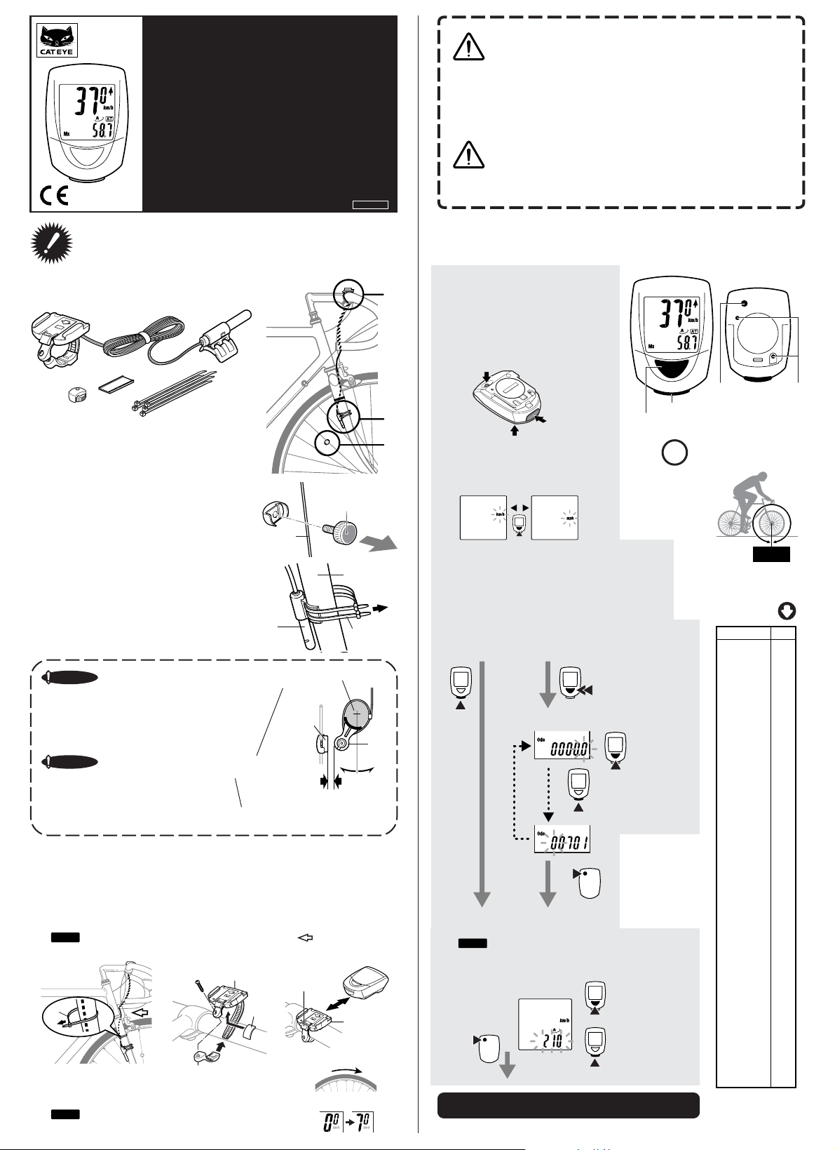
Installation of the Computer on Your Bike
The computer is combined with the following parts.
1
6
5
1 Bracket
2 Cord
3 Sensor
4 Sensor Rubber Pad
2
7
5 Magnet
6 Bracket Rubber Pad
7 Nylon Ties (5)
3
4
Copyright © 2002 CAT EYE Co. Ltd.
CCMMT4-021210 066600230 1
3
2
1
• Pay attention to the road or trail! Do not be distracted by the
computer.
•Be sure to securely mount the magnet, the sensor, and the
Warning
bracket on your bicycle. Periodically check to insure they are
mounted securely and the screws are not loosen.
• Keep batteries out of reach of small children. Dispose of batteries according to local regulations.
• Avoid unnecessary prolonged exposure to the sun. Never attempt to disassemble the computer head.
• Don’t use thinner, benzene or alcohol to wipe the surface of the
Important
Note
computer. They may damage the surface of computer.
Computer Set-up (For 1st use or after replacing the battery)
All Clear
1
Push three buttons (MODE, START/
STOP and SET) at the same time.
* Do this procedure without fail for
stable measurement when you use
this system for the first time and every
time the battery is replaced.
SET Button
START/STOP
Button
MODE Button
Select The Measurement Unit
2
Select the measurement unit, kilometer
or mile, by pushing the MODE button.
START/STOP Button
MODE Button
You need to know the tire
!
circumference (L cm) beforehand.
SET Button
Contact Point
Mount the magnet
1
5 on a spoke of the front wheel so that the surface
of the magnet will face the sensor.
Mount sensor and adjust the gap between the
2
magnet and the sensor.
Secure the sensor 3 with the larger nylon ties 7 at
the appropriate place and in the right direction.
Important Note
Mount the sensor 3 at the appropriate position so that the center of the
magnet 5 will align with the
marked line on the sensor when the
wheel is rotated.
Important Note
Rotate the sensor on the front fork to
adjust the gap between the sensor
and the magnet 5 within 5 mm, and
secure it with the nylon ties.
Mount The Bracket
3
Secure the cord on the front fork with the nylon ties (smaller ones) 7 and coil it around the
brake cable that leads to the handle bar.
Put the rubber pad 6 on the bracket 1 and secure the bracket on the handle bar with the
screw. Slide the computer into the bracket until you hear the click sound
The contact points are automatically closed. When you need to remove the computer, slide
forward the computer with the lever pushed simultaneously.
Note
Allow enough wire clearance in the area marked with an to insure that you can
turn the handlebar from left to right without pulling the wire.
7
Basic Functions Test
4
Rotate the front wheel gently and see if the computer indicates the
running speed.
Note
When the computer does not indicate the speed, check
the position of the magnet and the sensor.
Center
1
6
Spoke
3
Marked Line
Lever
5
Sensor Side
Front Fork
7
Front Fork
5
3
Within 5 mm
Slide
1
Rotate the front wheel.
OK
Kilometer
Choose Either of The Followings.
•When you want to input the reading of the currently
used odometer, keep pressing the MODE button for
two seconds and input the reading.
•When you want to start the odometer from zero,
push the START/STOP button.
Starting the odometer from zero.
ST/STOP
Set The Tire Circumference
3
Set the tire circumference in cm.
Note
You can easily set it by referring to the chart shown
right.
Setting is completed by pushing the SET button.
(the screen will show the time measurement in this state)
* The auto mode is ON in this state.
Mile
MODE
Retaining the current odometer reading
(the odometer starts from the reading you
inputted)
For two seconds.
MODE
Input the current reading of odometer.
MODE
Move the
decimal point.
ST/STOP
SET
Increase the
number.
Max. 300 cm
Decrease
the number
Min. 100 cm
Preparation Complete.
Increase the
number.
L cm
You can refer to the guide
chart to roughly know the
tire circumference.
Tire size
14 x 1.50 102
14 x 1.75 106
16 x 1.50 119
16 x 1.75 120
18 x 1.50 134
18 x 1.75 135
20 x 1.75 152
20 x 1-3/8 162
22 x 1-3/8 177
22 x 1-1/2 179
24 x 1 175
24 x 3/4Tubular 178
24 x 1-1/8 179
24 x 1-1/4 191
24 x 1.75 189
24 x 2.00 192
24 x 2.125 196
26 x 7/8 192
26 x 1(59) 191
26 x 1(65) 195
26 x 1.25 195
26 x 1-1/8 190
26 x 1-3/8 207
26 x 1-1/2 210
26 x 1.40 200
26 x 1.50 201
26 x 1.75 202
26 x 1.95 205
26 x 2.00 206
26 x 2.10 207
26 x 2.125 207
26 x 2.35 208
26 x 3.00 217
27 x 1 215
27 x 1-1/8 216
27 x 1-1/4 216
27 x 1-3/8 217
650 x 35A 209
650 x 38A 212
650 x 38B 211
700 x 18C 207
700 x 19C 208
700 x 20C 209
700 x 23C 210
700 x 25C 211
700 x 28C 214
700 x 30C 217
700 x 32C 216
700C Tub ular 213
700 x 35C 217
700 x 38C 218
700 x 40C 220
Tire size is usually shown
on the sidewall of tires.
L(cm)
Page 2
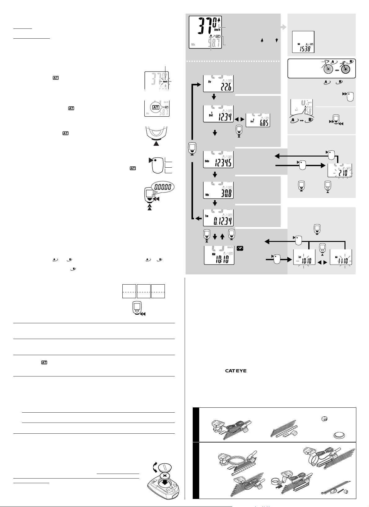
Computer Operations
Selection of the data-display mode (bottom of the screen).
Pressing the MODE button changes the functions in the sub-display.
Clock Time - In Elapsed Time, press and hold the Mode button for two seconds to display Clock
Time. Pressing the Mode button again will return the sub-display to Elapsed Time.
Trip Distance 1 and 2 – The computer has two separate trip distances. Trip Distance 2 is reset
independently. It can be used to record distance within a ride or multiple days distances. In Trip
Distance 1, press and hold the Mode button to select Distance 2. You will continue to view this
distance until you select Distance 1 with the same procedure.
Start or Stop of Measurements.
The computer can be programmed to run in either MANUAL MODE or
AUTO TIME MODE. In Manual Mode you must press the START / STOP
button to turn on and off the Timer, which records Distance and Average
Speeds. In Auto Time
pending on a signal from the sensor.
When speed is detected by the computer and the Timer is running, the
km/h or mph will flash. Speed will appear on the computer screen and
the Odometer will record, regardless if the Timer is running or not.
the computer turns the Timer on and off de-
• Auto Time Mode (Automatic Measurement)
In AUTO TIME mode, the letters
Elapsed time, Average and Distance are recorded automatically and the
Timer, stops when the speed stops. In this mode the START/STOP button
is not operable.
will appear on the computer screen.
• Manual Measurements
When you don’t see the icon
measurements by pushing the START/STOP button.
When you push the button, measurements of Elapsed Time, Average
Speed, Trip Distance 1 and 2 are started and they are stopped with the
second push of the button.
on the screen, you can start or stop the
• How to set ON or OFF the auto-mode
Push the SET button on the back side of the computer while Elapsed
Time, Average Speed, Trip Distance 1 or 2 is displayed, then the icon
is lit” (ON) or turned OFF.
Resetting Elapsed Time, Trip Distance, Average Speed and Max Speed.
Press and hold the MODE and START/STOP buttons for 2 sec. in either
the Elapsed Time, Trip Distance 1, Average Speed or Maximum Speed
functions to reset these functions. The Odometer and Trip Distance 2 are
not reset. See below for details.
• Resetting Trip Distance 2
Trip Distance 2 is reset independently. When Trip Distance 2 is on the
screen, press and hold both the MODE and START/STOP buttons to reset.
Computer Functions
• Power-saving Function
When no signal has been received for about one hour, the computer goes into the power savings
mode to only display the Clock. When any button is pushed or the wheel is rotated, the computer
screen reappears.
• Dual Tire Size
You can program two,
versa to enable the system to be used by two bicycles which have different tire sizes. The computer program for circumference
this for MTB's.
• Moving Elapsed Time, Average Speed and Maximum
Speed to the upper display.
You can move the Elapsed Time, Average and Max Speed
displays to the upper display for easier viewing. Hold the
START/STOP button for 2 sec. and the sub-display will appear in the upper display. Hold the START/STOP button
again for 2 sec. and the display returns to the normal set up.
and , tire circumferences and can easily switch to or vise
is programmed for low speed use. We recommend to use
Elapsed
Time
Minute
Second
Hour
Troubleshooting
No display appears.
Is the battery dead?
Replace it by the new one and do all clear procedure.
Strange data appears
Do all clear procedure (write down the number of Odometer if possible before doing the all
clear procedure and input it manually after choosing the measurement unit).
Measurements do not start when the START/STOP button is pushed.
Is the icon
ON?
Turn the Auto-Mode off to enable the start or stop of the measurements by manual operation of the button.
No speed data is displayed.
(If the speed data is not displayed, have the contact points short-circuited by a metal plate. In the
case that this short-circuiting is detected by the computer, the computer is considered normal
and the bracket and sensor may possibly have the cause of trouble.)
Is the gap between the sensor and the magnet too big? (should be within 5 mm)
Does the marked line of the sensor align with the center of the magnet?
Adjust the position of the magnet and the sensor.
Make sure that the contact points of the bracket or of the main body are free from dirt.
Wipe the contact points clean.
Is the cord not broken? Even if the outside of the cord looks normal, a breakage in the wire can occur.
Replace the bracket and sensor set with a new one.
Maintenance
• To clean the computer or the attached parts, use diluted neutral detergent
on a soft cloth, and wipe it off with a dry cloth.
Replacing The Battery
When the display gets dim, replace the battery. If you want to retain and
use the current reading of odometer, write down the odometer data before
replacing the battery.
• Put a lithium battery CR2032 in the computer with the (+) mark facing up.
• After replacing the battery, do the necessary set-up of the computer in
accordance with "Computer Set-up".
Measurement
ST/STOP
SET
ST/STOP
For 2 sec. at the
same time
Average
Maximum
Speed
Speed
Av
SPD SPD
ST/STOP
Close
Open
Unit Icon
MODE
Mx
Tm
Av
Dst
Upper
Part
Lower
Part
Measurement Display
0.0 (4.0) - 105.9 km/h
Speed
[0.0 (3.0) - 65.9 mph]
Average Pace Arrow
It shows that the current speed is faster
or slower than the Average Speed.
Auto-mode Icon
When it is lit, the measurements
Wheel Icon
Indicates which wheel setting is selected.
Mode Selection Illustrations
(bottom of the screen)
MODE
For 2 sec.
MODE
are automatically started or stopped.
MODE
Av
Average Speed
0.0 -105.9 km/h
[0.0 - 65.9 mph]
Dst
Trip distance - 1
0.00 -999.99 km [mile]
Trip distance - 2
0.00 - 999.99 km
MODE
[mile]
* Resetting of Dst2 only
Odo
Odometer
0.0 - 99999 km [mile]
Mx
Maximum Speed
0.0 (4.0) - 105.0 km/h
[0.0(3.0) - 65.0 mph]
Tm
Elapsed Time
0:00’00” - 9:59’59”
Clock
0:00 - 23:59
[1:00 - 12:59]
SlowerFaster
Return to Clock display
SET
When the measurements
are stopped.
Specifications
Battery Life : --------------------------------- A Lithium Battery (CR2032), Approx:3 yrs
Control System : ---------------------------- 4-bit 1-chip micro-computer (with a crystal oscillator)
Display : -------------------------------------- Liquid crystal display
Sensing System : --------------------------- No-contact magnetic sensor
Range of Tire Circumference : ------------- 100 cm – 300 cm (Initial value – A:210 cm B:205 cm)
Range of Operational Temperature : ------ 0°C
Dimension and Weight(Computer) : ------ 38 x 54 x 17.5 mm [1-1/2 x 2-1/8 x 11/16"] / 28 g [1.0 oz]
* The factory-loaded battery life might be shorter than the above-mentioned specification.
* The specifications and design are subject to change without notice.
Limited Warranty
2-Year Warranty : Computer Head Only
If any trouble or damage occurs during normal use, the product computer will be repaired or replaced
free of charge. Type your name, address, telephone number or e-mail address, date of purchase and
the situation of trouble and send it back together with the product to the closest address below. Transportation charges shall be borne by the customer. After being repaired, the product will be shipped
back to the customer.
(approx:1 hrs per day usage)
– 40°C [32°F – 104°F]
(excluding the attached parts and deteriorated battery )
CO
.,L TD.
2-8-25, Kuwazu, Higashi Sumiyoshi-ku, Osaka 546-0041 Japan
Attn.: CAT EYE Customer Service Section
Service & Research Address for United States Consumers:
CAT EYE Service & Research Center
1705 14th St. 115 Boulder, CO 80302
Phone: 303-443-4595 Toll Free: 800-5CATEYE
Fax: 303-473-0006 e-mail: service@cateye.com
* Accessory parts are available for the customers as shown below.
#169-9300 [169-9305]
Bracket Sensor Kit [Long]
#169-9755
Attachment Kit
Standard Parts
#169-9350
Heavy Duty Wire and Bracket
Sensor Kit
#169-9303
Bracket Sensor Kit for Aero Bar
#169-9304
Optional Parts
Stem Mount Bracket Kit
Power Saving Screen
(When no signal is received for about one hour,
the computer switches to the power-saving mode)
You can program
two tire sizes and
use either of them.
How to select tire size or
Road MTB
Inputting the Tire
Circumference
Return to Odo
SET
When the measurements
are stopped
Setting The Clock Time
24 hour or 12 hour system is to
be used with km/h or mph unit respectively
SET
Set the hour Set the minute
#169-9302
[#169-9307]
Center Mount Bracket
Kit [Long]
When you push either of the
MODE button or the
START/STOP button or you
ride the bicycle, the display
comes back to the
measurement display.
When data other than Odo is
displayed
When the Odo data is
displayed
Increase
the number
MODE
MODE
URL: http://www.cateye.com
#169-9691
Wheel Magnet
#166-5150
Lithium Battery (CR2032)
#169-9760
Magnet for
Composite Wheel
Road MTB
Keep on pressing the
button for two seconds
Keep on pressing buttons
for 2 sec. at the same time
ST/STOP
SET
MODE
Range of setting:
100 - 300 cm
SET
Decrease
the number
ST/STOP
Increase the number
ST/STOP
Page 3

SET
ST/STOP
MODE
®
CAT EYE MITY 8
COMPTEUR DE VITESSE
CC-MT400
F: Manuel de l’utilisateur
• Faîtes attention à la route ou à la piste ! Ne vous laissez pas
distraire par le compteur.
• Assurez-vous de bien fixer l’aimant, le capteur et le support sur
Attention
votre vélo. Vérifiez régulièrement pour vous assurer qu’ils sont
fixés correctement et que les vis sont bien serrées.
• Gardez les piles hors de portés des enfants. Jetez les piles en
suivant les procédures locales.
MITY8
Brev. US N° 4633216/4642606/5226340/5236759 brev. et brev. dessin
Copyright en cours © 2002 CAT EYE Co., Ltd.
importante
• Evitez de le laisser longtemps au soleil quand ce n’est pas nécessaire. Ne jamais essayer d’ouvrir le compteur.
•Ne pas utiliser de diluant, benzène ou alcool pour essuyer la
Remarque
surface du compteur. Cela pourrait l’endommager.
Veuillez lire attentivement ces instructions avant d’essayer
d’installer et d’utiliser votre compteur CAT EYE MITY 8, afin
de comprendre les fonctions de ce produit.
Ne pas jeter ce manuel ; gardez-le dans un endroit facile d’accès.
Installation du compteur sur votre vélo
Le compteur est composé des pièces suivantes.
1
5
1 Support
2 Fil
3 Capteur
4 Cale en caoutchouc du capteur
Installez l’aimant
1
5 sur un rayon de la roue avant de telle sorte que
l’aimant soit en face du capteur.
Installez le capteur et réglez l’écart entre
2
l’aimant et le capteur.
Fixez le capteur 3 avec les grandes attaches nylon 7 au
bon emplacement et dans la direction approprié.
Remarque importante
Installez le capteur 3 à la position
appropriée de telle manière que
l’aimant 5 s’aligne sur la marque
du capteur quand la roue tourne.
Remarque importante
Faîtes pivoter le capteur sur la fourche avant pour régler l’écart entre le
capteur et l’aimant 5 à 5 mm ou
moins, et fixez-le avec les attaches
en nylon.
Installez le support
3
Fixez le fil sur la fourche avant avec les attaches en nylon (les petites) 7 et enroulez-le autour du
câble de frein qui monte jusqu’au guidon.
Mettez la cale en caoutchouc 6 sur le support 1 et fixez le support sur le guidon avec une vis.
Faîtes glisser le compteur dans le support jusqu’à ce que vous entendiez un clic
Les points de contacts sont automatiquement connectés. Lorsque vous devez enlever le compteur,
faîtes-le glisser vers l’avant, tout en appuyant sur le levier.
Remarque
Laissez suffisamment de jeu dans le fil dans la zone marquée par un afin de pouvoir
7
Testez les fonctions de base
4
Faîtes tourner doucement la roue et vérifiez que le compteur indique la
vitesse.
Remarque
Si le compteur n’indique pas la vitesse, vérifiez la position de
2
6
tourner le guidon de gauche à droite sans tirer sur le fil.
l’aimant et du capteur.
7
5 Aimant
6 Cale en caoutchouc du support
7 Attaches en nylon (5)
5
Réglage du compteur
(pour la première utilisation ou après le remplacement de la batterie.)
Réinitialisé
1
Appuyez sur les trois boutons (MODE,
3
3
4
2
1
5
Coté du
capteur
Fourche avant
7
3
Glissière
1
OK
3
Centre
1
Rayon
3
Fourche avant
Marque
5
Moins de 5 mm
Levier
6
Faîtes tourner la roue avant.
START/STOP et SET) en même temps.
* Effectuez cette procédure sans faute pour
obtenir une mesure stable lorsque vous
utilisez ce système pour la première fois,
puis à chaque fois que la pile est remplacée.
Bouton SET
Bouton
START/STOP
Bouton MODE
Sélectionnez l’unité de mesure
2
Sélectionnez l’unité de mesure, kilomètre ou
mile, en appuyant sur le bouton MODE.
Kilomètre
Sélectionnez l’une des options suivantes :
• Lorsque vous voulez entrer la valeur actuelle de l’odomètre, continuez à appuyer sur le bouton MODE pendant
deux secondes et entrez la valeur.
• Si vous voulez commencer avec l’odomètre à zéro, appuyer sur le bouton START/STOP.
Commencez avec
l’odomètre à zéro.
ST/STOP
Réglez la circonférence de la roue.
3
Réglez la circonférence du pneu en cm.
Remarque
Vous pouvez facilement la régler en vous référant à la
table de droite.
Le réglage se termine lorsque vous appuyez sur le bouton SET.
La préparation est terminée.
(A ce point, l’écran affichera la mesure du temps)
* Le mode auto est activé (ON).
Mile
MODE
Conservez la valeur actuelle de l’odomètre
(L’odomètre commence à partir de la valeur
que vous avez entrée.)
MODE
Entrez la valeur actuelle de l’odomètre.
ST/STOP
SET
Bouton MODE
Pendant 2 sec.
MODE
Déplacez la
virgule.
Augmentez le
nombre.
Max. 300 cm
Réduisez le
nombre
Min. 100 cm
Augmentez le
nombre.
Bouton SET
Bouton START/STOP
Vous devez connaître la circonférence du pneu (L cm) à
!
l’avance.
Vous pouvez consulter le tableau indicatif pour une évaluation de la circonférence du
pneu.
Point de contact
L cm
Taille du pneu
14 x 1.50 102
14 x 1.75 106
16 x 1.50 119
16 x 1.75 120
18 x 1.50 134
18 x 1.75 135
20 x 1.75 152
20 x 1-3/8 162
22 x 1-3/8 177
22 x 1-1/2 179
24 x 1 175
24 x 3/4
24 x 1-1/8 179
24 x 1-1/4 191
24 x 1.75 189
24 x 2.00 192
24 x 2.125 196
26 x 7/8 192
26 x 1(59) 191
26 x 1(65) 195
26 x 1.25 195
26 x 1-1/8 190
26 x 1-3/8 207
26 x 1-1/2 210
26 x 1.40 200
26 x 1.50 201
26 x 1.75 202
26 x 1.95 205
26 x 2.00 206
26 x 2.10 207
26 x 2.125 207
26 x 2.35 208
26 x 3.00 217
27 x 1 215
27 x 1-1/8 216
27 x 1-1/4 216
27 x 1-3/8 217
650 x 35A 209
650 x 38A 212
650 x 38B 211
700 x 18C 207
700 x 19C 208
700 x 20C 209
700 x 23C 210
700 x 25C 211
700 x 28C 214
700 x 30C 217
700 x 32C 216
700C Tubulaire 213
700 x 35C 217
700 x 38C 218
700 x 40C 220
La taille du pneu est habituellement indiquée sur
le coté des pneus.
Tubulaire
L(cm)
178
Page 4

Opérations du compteur
Sélection d’un mode d’affichage (bas de l’écran).
Appuyez sur le bouton MODE pour modifier les fonctions de l’affichage inférieur.
Heure - Dans “temps écoulé”, appuyez et maintenez le bouton MODE pendant deux secondes pour
afficher l’heure. Appuyez de nouveau sur le bouton MODE pour retourner à « temps écoulé ».
Distance du parcours 1 et 2 – Le compteur dispose de deux distances de parcours. La distance de
parcours 2 est réinitialisée indépendamment. Elle peut être utilisée pour enregistrer une distance pendant une sortie ou pendant des trajets de plusieurs jours. Dans distance de parcours 1, appuyez et
maintenez le bouton MODE pour sélectionner la distance 2. Vous continuerez à visualiser cette distance,
à moins de sélectionner distance 1 en utilisant la même procédure.
Début et fin des mesures.
Le compteur peut être programmé pour fonctionner en MODE MANUAL ou en
MODE AUTO TIME. En mode manuel, vous devez appuyer sur le bouton
START/STOP pour démarrer ou arrêter le chronomètre et enregistres les distances et les vitesses moyennes. Dans le mode Auto Time
démarre ou arrête le chronomètre en fonction du signal provenant du capteur.
Lorsque la vitesse est détectée par le compteur, et que le chronomètre est en
route, le km/h ou mph va clignoter. La vitesse apparaîtra sur l’écran du compteur et l’odomètre enregistrera, que le chronomètre soit en route ou non.
le compteur
• Mode Auto Time (Mesure automatique)
En mode AUTO TIME, les lettres
temps écoulé, la moyenne et la distance sont enregistrés automatiquement, et le
chronomètre s’arrête quand la vitesse s’arrête. Dans ce mode, le bouton START/
STOP ne fonctionne pas.
vont apparaître sur l’écran du compteur. Le
• Mesures manuelles
Lorsque l’icône
les mesure en appuyant sur le bouton START/STOP.
Lorsque vous appuyez sur le bouton, les mesures du temps écoulé, de la vitesse moyenne de la distance de trajet 1 et 2 sont mise en route et s’arrêtent en
appuyant à nouveau sur le bouton.
n’apparaît pas à l’écran, vous pouvez démarrer ou arrêter
• Comment activer ou désactiver le mode auto.
Appuyez sur le bouton SET à l’arrière du compteur pendant que le temps
écoulé, la vitesse moyenne, la distance du trajet 1 et 2 sont affichés, et l’icône
s’allume (activé) ou s’éteint (désactivé).
Réinitialisez le temps écoulé, la distance dez parcours la vitesse
moyenne et la vitesse Max.
Appuyez et maintenez les boutons MODE et START/STOP pendant 2 secondes
pour réinitialiser les fonctions de temps écoulé, distance de trajet 1, vitesse
moyenne ou maximale. L’odomètre et la distance de trajet 2 ne sont pas
réinitialisés. Voir ci-dessous pour plus de détails.
• Réinitialisez la distance de parcours 2
La distance de parcours 2 est réinitialisée indépendamment. Lorsque la distance de parcours 2 est à l’écran, appuyez et maintenez les boutons MODE et
START/STOP pour réinitialiser.
Fonctions du compteur
• Fonction d’économie d’énergie
Lorsque aucun signal n’est reçu pendant environ 1 heure, le compteur passe en mode économie d’énergie et affiche uniquement l’heure. Lorsqu’un bouton est appuyé ou que la roue tourne, l’écran du compteur réapparaît.
• Deux tailles de pneu
Vous pouvez programmer deux circonférences de pneu,
à oet vice et versa pour permettre l’utilisation sur deux vélos qui ont des tailles de pneu différentes. Le programme du compteur pour la circonférence
recommandons de l’utiliser pour un VTT.
• Faîtes passer le temps écoulé, la vitesse moyenne et la vi-
tesse maximale dans l’affichage supérieur.
Vous pouvez déplacer l’affichage du temps écoulé, de la vitesse
moyenne et maximale dans l’affichage supérieur pour les visualiser plus facilement. Appuyez sur le bouton START/STOP pendant
2 sec et l’affichage inférieur va apparaître dans l’affichage supérieur. Maintenez à nouveau le bouton START/STOP pendant 2
sec. et l’affichage retourne à la configuration normale.
et ,, et pouvez facilement basculer de
est prévu pour des petites vitesses. Nous
Tem ps
écoulé
Minute
Seconde
Heure
Dépannage
Aucun affichage.
Est ce que la pile est vide ?
Remplacez la pile avec une pile neuve et refaites toute la procédure d’initialisation.
Des données étranges apparaissent
Effectuez toute la procédure d’initialisation (Notez le chiffre de l’Odomètre si possible avant d’effectuer toute la procédure d’initialisation et entrez le manuellement après avoir choisi l’unité de
mesure).
Les mesures ne démarrent pas lorsque l’on appuie sur le bouton START/STOP.
Est ce que l’icône
Arrêtez le mode auto pour activer le bouton START/STOP et lancer ou arrêter manuellement les
mesures.
Les données concernant la vitesse ne sont pas affichées.
(Si les données concernant la vitesse ne sont pas affichées, court-circuitez les points de contact avec
une plaque de métal. Si le compteur détecte ce court-circuit, le compteur fonctionne normalement et la
cause du problème provient probablement du support et du capteur.)
Est ce que l’écart entre le capteur et l’aimant est trop grand ? (doit être inférieur ou égal à 5 mm)
Est ce que la marque sur le capteur s’aligne avec le centre de l’aimant ?
Réglez la position de l’aimant et du capteur.
Assurez-vous que les points de contact du support ou du compteur ne sont pas sales.
Nettoyez les points de contact.
Est ce que le fil n’est pas cassé ? Même si l’extérieur du fil à l’air normal, il est possible que le fil soit cassé.
Remplacez l’ensemble du support et du capteur.
est activée ?
Entretien
• Pour nettoyer le compteur ou les pièces, utilisez un détergent neutre avec un
chiffon doux et essuyez-le avec un chiffon sec.
Remplacer la pile
Lorsque l’affichage devient sombre, remplacez la pile. Si vous voulez conserver
et utiliser la valeur actuelle de l’odomètre, écrivez la avant de remplacer la pile.
• Insérez une pile au lithium CR2032 dans le compteur, avec la marque (+) vers le
haut.
• Après avoir remplacé la pile, effectuez la configuration nécessaire en suivant les
instructions données dans « Réglage du compteur ».
SET
ST/STOP
Simultanément
pendant 2 sec
Vitesse
moyenne
Av
VTS VTS
ST/STOP
Fermer
Ouvrir
Icône d’unité de
mesure
ST/STOP
Tm
Av
Dst
MODE
Vitesse
maximale
Partie
Mx
supérieure
Partie
inférieure
Affichage des mesures
0.0 (4.0) - 105.9 km/h
Vitesse
[0.0 (3.0) - 65.9 mph]
flèche de l’allure moyenne
Elle montre que la vitesse actuelle est plus
ou moins rapide que la vitesse moyenne.
Icône du mode auto
Lorsqu’elle est allumée, les mesures com-
Icône Roue
Indique quels paramètres de roue sont sélectionnés.
Illustrations de la sélection de mode
(bas de l’écran)
MODE
Pendant
2 sec.
MODE
mencent ou s’arrêtent automatiquement.
Av
Vitesse moyenne
0.0 -105.9 km/h
[0.0 - 65.9 mph]
Dst
Distance de parcours - 1
0.00 -999.99 km [mile]
MODE
Odo
Odomètre
0.0 - 99999 km [mile]
Mx
Vitesse maximale
0.0 (4.0) - 105.0 km/h
[0.0(3.0) - 65.0 mph]
Tm
Temps écoulé
0:00'00" - 9:59'59"
MODE
Heure
0:00 - 23:59
[1:00 - 12:59]
Moins rapidePlus rapide
Distance de
parcours - 2
0.00 - 999.99 km[mile]
* Re-initialisation de Dst-2
uniquement
Retournez à l’affichage de l’heure
SET
Lorsque les mesures
sont arrêtées.
Spécifications
Durée de vie de la pile : --------------------- Une pile au lithium (CR2032), Env. : 3 ans
Système de contrôle : ---------------------- Une puce de micro-ordinateur 4 bits (avec un oscillateur à cristal)
Affichage : ------------------------------------ Affichage à cristaux liquides
Système de capteur : ----------------------- Capteur magnétique sans contact
Plage de circonférence de pneu : ---------- 100 cm - 300 cm (valeur initiale - A:210 cm B:205 cm)
Plage de température de fonctionnement : -- 0°C - 40°C
Dimension et poids (compteur) : ---------- 38 x 54 x 17.5 mm / 28 g
* La durée de vie de la pile chargée en usine peut être plus courte que les spécifications indiquées ci-dessus.
* Les spécifications et le design peuvent être modifiés sans notification préalables.
Garantie limitée
2 ans de garantie : Tête du compteur uniquement (en excluant les pièces et la détérioration de la pile)
Si un quelconque problème ou dommage se produit au cours d’une utilisation normale, le compteur sera
réparé ou remplacé sans frais. Ecrivez votre nom, adresse, numéro de téléphone ou adresse email, date d’achat
et le problème, et faîtes les nous parvenir ainsi que le produit à l’adresse ci-dessous la plus proche. Les frais de
transport doivent être pris en charge par le client. Après la réparation, le produit sera renvoyé au client.
(env. : 1 heure par jour d’utilisation)
CO
.,L TD.
2-8-25, Kuwazu, Higashi Sumiyoshi-ku, Osaka 546-0041 Japan
Attn.: CAT EYE Customer Service Section
Service & Research Address for United States Consumers:
CAT EYE Service & Research Center
1705 14th St. 115 Boulder, CO 80302
Tel: 303-443-4595 Numéro gratuit: 800-5CATEYE
Fax: 303-473-0006 e-mail: service@cateye.com
* Les pièces sont disponibles comme indiqué ci-dessous.
#169-9300 [169-9305]
Ensemble de support de capteur [long]
#169-9755
Kit de fixation
Pièces standard
#169-9350
Ensemble Fil et support de haute
résistance
#169-9304
Pièces en option
Ensemble de support
de fixation pour potence
#169-9302
[#169-9307]
Ensemble de support pour
fixation centrée [long]
#169-9303
Ensemble de support du capteur
pour guidon Aéro
Ecran d’économie d’énergie
(Lorsque aucun signal n’est reçu pendant environ 1 heure,
le compteur bascule dans le mode d’économie d’énergie)
Vous pouvez
programmer deux
tailles de pneu et
utiliser l’une des deux.
Comment sélectionner la taille de pneu ou
Route VTT
Entrer la circonférence
du pneu
Retourner à Odo
SET
Lorsque les mesures sont
arrêtées
Régler l’heure
Le système sur 24 heures ou sur 12 heurs doit être
utilisé respectivement avec l’unité km/h ou mph
SET
Réglez l’heure Réglez les minutes
Lorsque vous appuyez sur le
bouton MODE ou sur le
bouton START/STOP, ou que
vous roulez avec le vélo,
l’affichage revient à l’affichage
des mesures.
Route VTT
Lorsque des données autres
que Odo s’affichent
Continuez à appuyer sur le
bouton pendant deux secondes.
Lorsque les données Odo
s’affichent
MODE
Continuez à appuyer sur les boutons
pendant 2 seconde simultanement
SET
Augmentez
le nombre
MODE
#169-9691
Aimant de roue
ST/STOP
Augmentez le nombre
MODE
ST/STOP
URL: http://www.cateye.com
#166-5150
Batterie au lithium (CR2032)
#169-9760
Aimant pour roue en
composite
SET
ST/STOP
Plage de paramètres :
100 - 300 cm
Réduisez
le nombre
Page 5

SET
ST/STOP
MODE
®
CAT EYE MITY 8
CYCLOCOMPUTER
CC-MT400
G: Bedienungsanleitung
MITY8
Patentnummern 4633216/4642606/5226340/5236759 Patent und Entwurf,
Bitte lesen Sie diese Anweisungen vorsichtig durch, so dass Sie die
Funktionen dieses Produkts verstehen, bevor Sie versuchen den
CATEYE MITY 8 Computer zu installieren und zu benutzen.
Bitte werfen Sie die Bedienungsanleitung nicht weg, sondern bewahren Sie diese an einem
Installation des Computers an ihrem Fahrrad
Der Computer wird mit den folgenden Teilen geliefert.
1 Halter
2 Kabel
3 Sensor
4 Sensor Gummipolster
leicht zugänglichen Ort.
1
6
5
2
7
5 Magnet
6 Gummipolster für Halter
7 Kabelbinder (5 Stück)
3
4
Pat. Pending, Copyright © 2002 CAT EYE Co., Ltd.
3
2
1
•Geben Sie acht auf die Straße, den Fahrradweg oder den Pfad auf
dem Sie fahren. Lassen Sie Ihre Aufmerksamkeit nicht durch den
Computer ableiten.
• Stellen Sie sicher, dass der Magnet, der Sensor und der Halter
Vorsicht!
sicher an Ihrem Fahrrad befestigt sind. Überprüfen Sie die Befestigung dieser Teile regelmäßig, um sicherzustellen dass die
Schrauben sich nicht gelockert haben.
• Halten Sie die Batterien aus der Reichweite von kleinen Kindern.
Entsorgen Sie die Batterien gemäß den lokalen Bestimmungen.
• Eine längere Aussetzung an Sonnenlicht ist zu vermeiden. Versuchen Sie niemals den Computer auseinander zu nehmen.
• Benutzen Sie niemals Verdünner, Benzol oder Alkohol um die
Wichtiger
Hinweis
Oberfläche des Computers zu reinigen. Sie können die Oberfläche ihres Computers damit beschädigen.
Computersetup (für die erste Nutzung oder nach Ersatz der Batterie)
Rücksetzung
1
Betätigen Sie die 3 Schalter MODE, START/
STOP und SET gleichzeitig.
* Diese Prozedur muss bei der ersten Nut-
zung und jedesmal nach dem Ersetzen der
Batterien durchgeführt werden, um stabile
Messwerte zu erhalten.
SET Schalter
START/STOP
Schalter
MODE Schalter
Selektion der Messeinheit
2
Betätigen Sie den MODE Schalter, um die
Messeinheit für Kilometer (kmh) oder Meilen (mph) zu definieren.
START/STOP Schalter
MODE Schalter
SET Schalter
Der Umfang des Reifens muss
Ihnen vorher bekannt sein
!
(Länge in cm).
Kontaktpunkt
Montieren Sie den Magnet
1
5 auf einer Speiche des Vorderrads, sodass die Oberfläche des Magnets auf den Sensor ausgerichtet ist.
Installieren Sie den Sensor
2
3 und justieren Sie dem Zwischenraum zwischen dem
Magnet und dem Sensor. Befestigen Sie den Sensor an einer geeigneten Stelle und in der richtigen Richtung. Benutzen Sie dafür die größeren Kabelbinder 7 .
Wichtiger Hinweis
Installieren Sie den Sensor 3 in einer geeigneten Position, so dass die
Mitte des Magnets 5 auf die markierte Linie des Sensors ausgerichtet ist, wenn das Rad dreht.
Wichtiger Hinweis
Drehen Sie den Sensor auf der vorderen Gabel, sodass der Zwischenraum zwischen dem Sensor und dem
Magnet 5 lediglich 5 mm beträgt
und befestigen Sie diesen mit den
Kabelbinder.
Installation des Halters
3
Befestigen Sie das Kabel an der Vordergabel mit den kleinen Kabelbinder 7 und wickeln Sie es um
das Bremskabel, welches zum Lenker führt.
Plazieren Sie das Gummipolster 6 auf dem Halter 1 und befestigen Sie den Halter am Lenker mit
der Schraube. Schieben Sie den Computer in den Halter 1 , bis Sie ein klickendes Geräusch hören.
Die Kontaktpunkte werden automatisch geschlossen. Falls Sie den Computer entfernen müssen,
dann schieben Sie diesen vorwärts während Sie gleichzeitig den Hebel andrücken.
Hinweis
Stellen Sie sicher, dass das Kabel lang genug ist, besonders in den Bereichen die mar-
kiert sind mit , sodass der Lenker nach links und nach rechts gedreht werden kann,
ohne an dem Draht zu ziehen.
7
Test der Grundfunktionen
4
Geben Sie dem vorderen Rad eine langsame Drehung und sehen Sie ob
der Computer die Geschwindigkeit anzeigt.
Hinweis
Falls der Computer keine Geschwindigkeit anzeigt, überprüfen
Sie bitte die Position des Magnets und die Ausrichtung mit
dem Sensor.
5
3
1
Mitte
Speiche
3
Markierte Linie
6
5
Seite des
Sensors
Vordergabel
7
Vordere Gabel
5
3
5 mm Zwischenraum
Hebel
Gleiter
1
Drehen Sie das vordere Rad.
OK
Kilometer
Wählen Sie eine der folgenden Optionen.
• Falls Sie den aktuellen Stand des Kilometerzählers eingeben wollen, dann Drücken Sie den MODE Schalter für
zwei Sekunden und geben danach den Stand ein.
• Falls Sie den Kilometerzähler auf Null einstellen wollen,
dann drücken Sie den START/STOP Schalter.
Kilometerzähler
auf Null einstellen.
ST/STOP
Raddurchmesser einstellen
3
Der Raddurchmesser wird in cm eingestellt.
Hinweis
Für eine einfache Einstellung benutzen Sie die Tabelle
auf der rechten Seite.
Die Einstellung wird abgeschlossen durch die Betätigung des
SET Schalters.
(In diesem Status wird der Bildschirm die Uhrzeit anzeigen)
* Der automatische Modus ist angeschaltet (ON) in diesem Stand.
Meilen
MODE
Den gegenwärtigen Stand des
Kilometerzählers beibehalten
(der Kilometerzähler startet ab den Stand Sie
eingegeben haben).
Für 2 Sekunden Drüken.
Geben Sie den derzeitigen Stand des Kilometerzählers ein.
MODE
ST/STOP
SET
Erhöhen Sie
die Zahl.
MODE
Verschieben Sie den
Dezimalpunkt.
Nummer
erhöhen:
Max. 300 cm
Nummer
verringern:
Min. 100 cm
Vorbereitungen beendet.
L cm
Bitte ziehen Sie die Tabelle in
dieser Bedienungsanleitung zu
Rat, um den ungefähren Umfang
ihres Reifens zu ermitteln.
Reifengröße
ETRTO
47-305 16 x 1.75 120
47-406 20 x 1.75 152
47-507 24 x 1.75 189
23-571 26 x 1(59) 191
37-590 26 x 1-3/8 207
40-559 26 x 1.50 201
47-559 26 x 1.75 202
50-559 26 x 1.95 205
54-559 26 x 2.00 206
57-559 26 x 2.125 207
32-630 27 x 1-1/4 216
18-622 700 x 18C 207
20-622 700 x 20C 209
23-622 700 x 23C 210
25-622 700 x 25C 211
28-622 700 x 28C 214
32-622 700 x 32C 216
37-622 700 x 35C 217
40-522 700 x 40C 220
Die Größe ihres Reifens wird
meistens auf der Seite des
Reifens angezeigt.
Umfang(cm)
14 x 1.50 102
14 x 1.75 106
16 x 1.50 119
18 x 1.50 134
18 x 1.75 135
20 x 1-3/8 162
22 x 1-3/8 177
22 x 1-1/2 179
24 x 1 175
24 x 3/4
Schlauchreifen
178
24 x 1-1/8 179
24 x 1-1/4 191
24 x 2.00 192
24 x 2.125 196
26 x 7/8 192
26 x 1(65) 195
26 x 1.25 195
26 x 1-1/8 190
26 x 1-1/2 210
26 x 1.40 200
26 x 2.10 207
26 x 2.35 208
26 x 3.00 217
27 x 1 215
27 x 1-1/8 216
27 x 1-3/8 217
650 x 35A 209
650 x 38A 212
650 x 38B 211
700 x 19C 208
700 x 30C 217
700C
Schlauchreifen
213
700 x 38C 218
Page 6

Betrieb des Computers
Auswahl des Displaymodus für die Datenanzeige (unten am Bildschirm).
Drücken des Schalters MODE verändert die Funktion der Unteranzeige.
Uhrzeit / Gesamtzeit: Drücken und halten Sie den Schalter MODE für zwei Sekunden um die Uhrzeit
anzuzeigen. Erneutes Drücken des Schalters MODE kehrt zurück zur Anzeige der Gesamtzeit in der
Unteranzeige.
Fahrtdistanz 1 und 2 – Der Computer kann zwei verschiedene Fahrtdistanz speichern. Fahrtdistanz 2
wird unabhängig zurückgestellt. Dieser Zähler dient vor allem zum messen von Teilstrecken. Drücken
und Halten Sie den MODE Schalter in der Funktion Fahrtdistanz 1, um Fahrtdistanz 2 zu selektieren.
Diese Fahrtdistanz wird solange angezeigt, bis die Funktion zurück zu der Fahrtdistanz 1 unter Nutzung
derselben Prozedur verändert wird.
Start oder Stopp von Messungen.
Der Computer kann entweder auf MANUAL MODE (manuellen Modus) oder AUTO
TIME MODE (automatischer Zeitmodus) programmiert werden. In dem manuellen
Modus müssen Sie den START / STOP Schalter Drücken um den Zeitmesser anoder auszustellen, mit dem die Distanz und die durchschnittliche Geschwindigkeit gemessen werden. In dem Auto Time
Zeitmesser gemäß eines Signals vom Sensor an- oder ausstellen.
Wenn der Zeitmesser aktiv ist und der Computer eine Geschwindigkeit feststellt,
dann wird die Anzeige "km/h" oder "mph" blinken. Die Geschwindigkeit wird auf
dem Bildschirm des Computers angezeigt und der Kilometerzähler wird die gefahrene Distanz festhalten, ungeachtet ob der Zeitmesser aktiv oder inaktiv ist.
Modus wird der Computer den
Piktogramm für die
Messeinheit
• Auto Time Modus (automatische Messungen)
In dem AUTO TIME Modus werden die Buchstaben
Computers angezeigt. Die Laufzeit, die durchschnittliche Geschwindigkeit und
die Distanz werden automatisch festgehalten und der Zeitmesser pausiert, wenn
keine Geschwindigkeit mehr gemessen wird. In diesem Modus ist der START/
STOP Schalter nicht aktiv.
auf dem Bildschirm des
• Manuelle Messungen
Wenn das Piktogramm
Messungen starten oder stoppen, indem Sie den START/STOP Schalter Drücken.
Mit einer ersten Betätigung dieses Schalters werden die Messungen für die Laufzeit,
die durchschnittliche Geschwindigkeit, sowie die Fahrtdistanz 1 und 2 gestartet, und
werden mit einer zweiten Betätigung des Schalters wieder gestoppt.
• Wie der Auto-Mode Modus an- ausgestellt wird
Wenn Sie den SET Schalter auf der Rückseite des Computers Drücken, während die Laufzeit, die durchschnittliche Geschwindigkeit, und die Fahrtdistanz
1 oder 2 angezeigt werden, dann leuchtet das Piktogramm
oder abgestellt (OFF).
Rücksetzung der Laufzeit, Fahrtdistanz, durchschnittliche Geschwindigkeit und maximalen Geschwindigkeit.
Um die Laufzeit, Fahrtdistanz, durchschnittliche Geschwindigkeit und maximale Geschwindigkeit zurückzusetzen, Drücken und Halten Sie den MODE und
den START/STOP Schalter für zwei Sekunden, während eines dieser Funktionen aktiv ist. Der Kilometerzähler und die Fahrtdistanz 2 werden nicht zurückgesetzt. Siehe unten für weitere Details.
• Rücksetzung von Fahrtdistanz 2
Fahrtdistanz 2 wird unabhängig von den anderen Funktionen zurückgesetzt.
Wenn die Fahrtdistanz 2 am Bildschirm angezeigt wird, Drücken und Halten Sie
den MODE und den START/STOP Schalter um die Rücksetzung auszuführen.
Computer Funktionen
• Energiesparfunktion
Wenn der Computer während einer Stunde keine Signale empfangen hat dann wird der Energiesparmodus aktiviert und lediglich die Uhrzeit angezeigt. Falls irgendein Schalter betätigt wird oder das Rad
sich dreht, dann wird der Bildschirm des Computers wieder aktiviert.
nicht auf dem Bildschirm erscheint, dann können Sie
und ist an(ON),
ST/STOP
SET
MODE
ST/STOP
Für 2 Sekunden
gleichzeitig Drüken
Tm
Av
Dst
• Zwei Reifengrößen
Um das System auf unterschiedlichen Fahrrädern mit unterschiedlichen Reifengrößen benutzen zu können, kann man zwei unterschiedlich große Reifen,
zwischen diesen beiden Größen hin- und herschalten. Das Programm des Computers für den Umfang
ist für die Nutzung bei niedrigeren Geschwindigkeiten programmiert. Wir empfehlen die Nutzung
dieser Einstellung für Geländefahrräder.
• Laufzeit, durchschnittliche Geschwindigkeit und maximale
Geschwindigkeit nach dem oberen Display umschalten.
Für eine bessere Übersicht kann die Anzeige der Laufzeit, der
durchschnittliche Geschwindigkeit und der maximalen Geschwindigkeit auf den oberen Display umgestaltet werden. Drücken und
Halten Sie den START/STOP Schalter für zwei Sekunden, wonach
die Unteranzeige in dem oberen Display erscheinen wird. Drücken
und Halten Sie den START/STOP Schalter nochmals für zwei Sekunden um das Display in den Standard Modus zurückzusetzen.
und , programmieren und auf einfache Weise
Laufzeit Durchschnittliche
Minute
Sekunde
Stunde
Maximale
Geschwindigkeit
Geschwindigkeit
Av
(Durchschnitt)Mx(Maximum)
SPD
SPD
(Geschwindigkeit)
(Geschwindigkeit)
ST/STOP
Oberer
Tei l
Unterer
Tei l
Fehlersuche und -beseitigung
Problem: Keine Anzeige auf dem Display.
Ist die Batterie leer?
Ersetzen Sie die Batterie mit einer neuen und führen Sie die Rückstellungsprozedur aus.
Problem: Ungewöhnliche Daten werden angezeigt
Führen Sie Rückstellungsprozedur aus (falls möglich, notieren Sie den Stand des Kilometerzählers
bevor Sie die Rückstellungsprozedur ausführen, sodass Sie diesen Wert manuell wieder eingeben
können, nachdem Sie die Messeinheit ausgewählt haben).
Problem: Der Messvorgang wird nicht aktiviert wenn der START/STOP Schalter gedrückt wird.
Ist das Piktogramm
Schalten Sie Auto-Mode ab, sodass die Messungen durch manuelle Betätigung des Schalters ak-
tiviert oder abgestellt werden können.
Problem: Keine Geschwindigkeitsdaten werden angezeigt.
(Falls keine Geschwindigkeit Daten angezeigt werden, dann kann es sein, dass die Kontaktpunkte kurzge-
schlossen sind. Falls dieser Kurzschluss von dem Computer erkannt wird, dann funktioniert der Computer normal und das Problem kann möglicherweise durch den Halter und den Sensor verursacht werden.)
Ist der Zwischenraum zwischen dem Sensor und dem Magnet zu groß?
(Dieser Zwischenraum sollte 5 mm betragen).
Ist die maskierte Linie des Sensors auf die Mitte des Magnets ausgerichtet?
Korrigieren Sie die Position des Magnets und des Sensors.
Stellen Sie sicher, dass die Kontaktpunkte des Halters oder das Hauptkörpers nicht schmutzig sind.
Reinigen Sie die Kontaktpunkte.
Ist das Kabel defekt? Das Kabel kann unterbrochen sein, auch wenn es äußerlich normal auszieht.
Tauschen Sie den Halter und den Sensor gegen neue Teile aus.
ON zu sehen?
Wartung
• Benutzen Sie ein verdünntes Reinigungsmittel und ein weiches Tuch um den
Computer und die angeschlossenen Teile zu reinigen. Wischen Sie die gereinigten Teile danach mit einem trockenen Tuch ab.
Ersatz der Batterie
Die Batterie muss ersetzt werden, wenn die Anzeige verdunkelt. Falls Sie den
aktuellen Wert des Kilometerzählers bewahren wollen, dann müssen Sie die Kilometerzahl vor der Entfernung der Batterie aufschreiben.
• Stecken Sie eine Lithiumbatterie (CR2032) in den Computer, mit dem (+) Zei-
chen nach oben.
• Der Computer muss gemäß den Anweisungen in dem Abschnitt "Computer-
setup" neu initialisiert werden, nachdem die Batterie ausgetauscht wurde.
Schließen
Öffnen
Messung Display
Geschwindigkeit
Durchschnitt Tempo Pfeil
Dies zeigt an, dass die gegenwärtige
Geschwindigkeit schneller oder langsamer
als die durchschnittliche Geschwindigkeit ist.
Auto-mode Piktogramm
Rad Piktogramm
Zeigt an welche Einstellung
für das Rad selektiert wurde.
Beispiele des selektierten Modus
(unten am Display)
MODE
Für 2 Sek.
MODE
Wenn dieses Piktogramm erleuchtet ist, dann
werden Messungen automatisch gestartet
oder gestoppt.
MODE
Technische Daten
Lebensdauer der Batterie : ----------------- Eine Lithiumbatterie (CR2032), ca. 3 Jahre
Steuerungssystem : ------------------------- 4-bit 1-chip Mikrocomputer (mit Quarz-Taktgeber)
Display : -------------------------------------- LCD-Schirm
Sensorsystem : ------------------------------ Kontaktloser magnetischer Sensor
Bereich des Reifenumfangs : -------------- 100 cm - 300 cm (Ersteinstellung - A:210 cm B:205 cm)
Bereich der Betriebstemperatur : ---------- 0°C - 40°C
Dimensionen und Gewicht (Computer) : -- 38 x 54 x 17.5 mm / 28 g
* Die Lebensdauer der mitgelieferten Batterie kann möglicherweise kürzer sein, als der oben genannte Wert.
* Die technischen Daten und der Entwurf können ohne vorherige Benachrichtigung abgeändert werden.
Begrenzte Garantie
2 Jahre Garantie auf das Computergerät selbst (exklusive der angeschlossenen Teile und der Batterie).
Der Computer wird kostenlos ersetzt oder repariert, falls Fehler oder Probleme während einer normalen Nutzung auftreten. Schicken Sie das Gerät an die nächste der unten angegebenen Adressen zurück, unter Angabe
Ihres Namens, Ihrer vollständige Adresse, der Telefonnummer oder E-Mail-Adresse wo Sie zu erreichen sind,
dem Einkaufsdatum und einer Beschreibung des Fehlers oder Problems. Transportkosten gehen zu Ihren Lasten. Das Produkt wird nach der Reparatur an Sie zurückgeschickt.
* Die an Kunden lieferbaren Zubehörteile werden unten angegebenen.
#169-9300 [169-9305]
Halter-Sensor Bausatz (lang)
Standardteile
#169-9350
Extra dickes Hochleistungskabe, HalterSensor Bausatz
#169-9304
Stabhalter- Bausatz
Zubehörteile (Option)
0.0 (4.0) - 105.9 km/h
[0.0 (3.0) - 65.9 mph]
LangsamerSchneller
Av
Durchschnittliche
Geschwindigkeit
0.0 -105.9 km/h
[0.0 - 65.9 mph]
Dst
Fahrtdistanz - 1
0.00 -999.99 km [Meilen]
Fahrtdistanz - 2
0.00 - 999.99 km
MODE
[Meilen]
* Nur Dst-2 kann zurückgesetzt werden
Odo
Kilometerzähler
0.0 - 99999 km [Meilen]
Mx
Maximum
Geschwindigkeit
0.0 (4.0) - 105.0 km/h
[0.0(3.0) - 65.0 mph]
Tm
Laufzeit
0:00’00” - 9:59’59”
Zurück zu der Uhranzeige
Uhr
0:00 - 23:59
[1:00 - 12:59]
SET
Wenn die Messungen
gestoppt sind.
(bei einer durchschnittlichen Nutzung von einer Stunde pro Tag)
CO
.,L TD.
2-8-25, Kuwazu, Higashi Sumiyoshi-ku,Osaka 546-0041 Japan
z. Hdn.: CAT EYE Customer Service Section
Für Kunden in den USA:
CAT EYE Service & Research Center
1705 14th St. 115 Boulder, CO 80302
Telefon: 001 303-443-4595 Gebührenfreies Telefon: 800-5CATEYE
Fax: 001 303-473-0006 E-mail: service@cateye.com
#169-9755
Befestigungssatz
#169-9303
Halter-Sensor Bausatz für Aero-Lenkstange
Energiesparender Bildschirm
(Der Computer schaltet um auf einen energiesparenden Modus,
wenn kein Signal innerhalb einer Stunde empfangen wurde)
Sie können zwei unterschiedliche
Reifengrößen programmieren
und selektieren, welche von
beiden Sie benutzen möchten.
Auswahl der Reifengrößen oder
Road (Straße) MTB (Gelände)
Eingabe des
Reifenumfangs
Zurück zum Kilometerzähler (Odo)
SET
Wenn die Messungen
gestoppt sind
Uhrzeit einstellen
Das 24- oder das 12-Stunden-System muss
entsprechend mit den Einstellungen "km/h" oder
"mph" eingestellt werden.
SET
Stunde einstellen Minuten einstellen
#169-9302
[#169-9307]
Halter-Bausatz für
Lenkemitte (lang)
Falls Sie den MODE oder den
START/STOP Schalter
betätigen oder auf dem
Fahrrad fahren, dann wird das
Display wieder aktiviert und
die Messungen werden wieder
angezeigt.
Road (Straße) MTB (Gelände)
Wenn andere Daten als die
Kilometerzahl (Odo)angezeigt
werden:
Drücken und Halten
Sie den Schalter für
zwei Sekunden.
Wenn die Kilometerzahl
angezeigt wird:
MODE
Drücken und Halten Sie die
Schalter gleichzeitig für zwei
Sekunden.
Einstellungsbereich:
100 - 300 cm
SET
Nummer
erhöhen
MODE
Website: URL: http://www.cateye.com
#169-9691
Radmagnet
ST/STOP
Die Nummer erhöhen
MODE
ST/STOP
#166-5150
Lithiumbatterie (CR2032)
#169-9760
Magnet für
Verbundrad
SET
Nummer
verringern
ST/STOP
Page 7

SET
ST/STOP
MODE
®
CAT EYE MITY 8
サイクロコンピュータ
CC-MT400
J: 取扱説明書
MITY8
U.S. Pat. Nos.4633216/4642606/5226340/5236759 Pat. and Design Pat. Pending
お使いの前にこの説明書を最後までよくお読みください。
この製品の機能をよく理解された上でご愛用ください。この説明書はお読みに
なった後も捨てずに、いつでも見られる状態で保管願います。
自転車への取付け
コンピ ュータ以 外に次の部品が付属しています。
全て揃っているか取付け前にご確認ください。
1 ブラケット
2 コード
3 セン サー
4 セン サーゴム 座
1
2
3
4
1
5
2
6
7
5 マグネット
6 ゴムパッド
7 ナイロンタイ(5本)
3
マグネットを取付けます
前輪のスポークにマグネット5をマグ ネット面がセン
サーに対面するように取付けます。
センサーを取付けて間隔を調整します
センサ ー3は位置がズレないように注意してナイロ
ンタイ7で固定します 。
重 要
前輪が回転したときマ
グネット5 の中心がセン
サー3の指示線を通過する
位置に固定してください。
重 要
センサーを回転させて
マグネット5との すきまが
5mm以内になるように調整
し、ナイロンタイをしっかりと
締めつけます。
5
ブラケットを取付けます
コードはナイロンタイ7でフォークに 止め、ブレ ーキ ケ ーブ ルに巻き付けてハンドルまで
配線します。
ブラケット1にゴムパッド6をはめ、ハンドルにネジでしっかりと固 定します。
コンピ ュータを「カチッ」と音が するまで差し込こむと、接点は自動的に接続されます。外
す時はレバーを押しながら前方へスライドし ます 。
注 意
部分はハンドルを回したときにコードが引っぱられないように長さを調 整します。
7
動作テストをします。
前輪を軽く回し、コンピ ュー タに 速 度表示されるか確認します。
注 意
速度表示しないときは、マグネットとセ ン サ ー の位置関
係を再度確認してください。
3
・ 走行中はコンピュータに気を取られないで、安全走行を心掛け
てください 。
・マグネット・センサー・ブラケットはしっかりと自転車に 取 付け、
警告
定期的にガタやネジの緩みが無いか点検してください。
・ 使用済みの電池は誤って飲み込まないように管理し、定められ
た方法で処理してください。
・ 炎天下の放置は避けてください。またコンピュータは 分 解しな
いでください。
・コンピュータや附属品を拭くときに シンナー、ベンジン、アル
注意
コール 等 は表面を傷めますので使わないでください。
Copyright © 2002 CAT EYE Co. Ltd.
コンピュータの準備(初めて使うとき・電池交換した後)
オールクリア操作をします
1
3
4
2
1
5
センサ ー側
スポーク
フロントフォーク
3
指示線
5
中心
1
6
レバー
7
フロントフォーク
3
5mm以内
スライド
1
前輪を回す
OK
3つのボタン(MODE・ST/STOP・
SETボタン)を同時に押します。
※安定した計測を行うため、初めて使う
ときや 電 池 交 換 の 後 に必ず行います。
SETボタン
ST/STOPボタン
表面MODEボタン
計測単位を選択します
2
MODEボタンでキロメートルかマイル
か、計測する単位を選択します。
キロメートル
次のどちらかを選択します。
・今まで使っていたメータの積算距離を引継ぐ
ときは MODEボタンを2秒間押します。続けて
今までの積算距離を入力します。
・積算距離を0からスタートさせる時はST/STOP
ボタンを押します。
積算距離を
0から始めるとき
ST/STOP
タイヤ周長をセット
3
自転車のタイヤ外周の長さをセンチ単位でセットします。
参 考
右のタイヤ周長ガイドを活用すると便利です。
SETボタンで確定され設定が完了します。
準備完了(計測画面・走行時間へ)
マイル
MODE
積算距離を引継ぐとき
(積算距離は入力した数値から始まります)
今までの積算距離を入力します
ST/STOP
SET
MODEボタン
2秒間
MODE
数字をプラス
MODE
桁の移動
数字をプラス
最大300cm
数字をマイナス
最小100cm
※オートモードはオンの 状態で
セットされます
SETボタン
START/STOPボタン
予めタイヤの周長(Lcm)
!
を調べます。
簡易的には
タイヤ周 長ガイド
を活用してください 。
タイヤサ イズは 通 常タイヤ
の側面に記載されています。
L cm
タイヤサ イズ
14 x 1.50 102
14 x 1.75 106
16 x 1.50 119
16 x 1.75 120
18 x 1.50 134
18 x 1.75 135
20 x 1.75 152
20 x 1-3/8 162
22 x 1-3/8 177
22 x 1-1/2 179
24 x 1 175
24 x 3/4Tubular 178
24 x 1-1/8 179
24 x 1-1/4 191
24 x 1.75 189
24 x 2.00 192
24 x 2.125 196
26 x 7/8 192
26 x 1(59) 191
26 x 1(65) 195
26 x 1.25 195
26 x 1-1/8 190
26 x 1-3/8 207
26 x 1-1/2 210
26 x 1.40 200
26 x 1.50 201
26 x 1.75 202
26 x 1.95 205
26 x 2.00 206
26 x 2.10 207
26 x 2.125 207
26 x 2.35 208
26 x 3.00 217
27 x 1 215
27 x 1-1/8 216
27 x 1-1/4 216
27 x 1-3/8 217
650 x 35A 209
650 x 38A 212
650 x 38B 211
700 x 18C 207
700 x 19C 208
700 x 20C 209
700 x 23C 210
700 x 25C 211
700 x 28C 214
700 x 30C 217
700 x 32C 216
700C Tub ular 213
700 x 35C 217
700 x 38C 218
700 x 40C 220
L(cm)
接点
Page 8

コンピュータの操作
選択(下段)データの切替え
MODEボタンを押すと選択データは右図(計測画面)の順に切替ります。
走行時間を表示してMODEボタンを2秒間押し続けると時刻に切替ります。MODEボ
タンを押すと走行時間に戻ります。
走行距離を表示してMODEボタンを2秒間押し続けると走行距離の1と2を切替えること
ができます。1と2は 次に切替えるまで 選 択したほうが表示されます。
計測のスタート/ストップ
計測中は計測単位アイコン(km/hまたは mph )が点滅します。
積算距離と最高速度は計測の開始・停止にかかわらず更新されます。
計測は手動と自動に切替えることができます。
●オートモ ード(自動計測)
アイコンが点灯しているときは計測を自動で行います。これ
画面に
をオートモードと呼 び車輪の動きを検知して自動的に計測のスタートと
ストップを行 い ます 。(
が点灯している時は ST/ STOPボタンで計測
をスタート・ストップ で きませ ん )
●手動計測
画面の
アイコンが消灯している時はST/STOPボタンを使って計測
のスタートとストップをします。
ボタンを押すと走行時間・平均速度・走行距離1・走行距離2の計測を
開始し、もう一 度 押 すと 停 止します 。
●オートモ ード をオンまたはオフするには
走行時間・平均速度・走行距離の1または2を表示して、裏面のSETボ
タンを 押します。
アイコンが点灯(オン)または消灯(オフ)に切替り
ます。
走行時間、走行距離、平均速度、最高速度のリセット
積算距離・走 行距離2以外の表示の時、MODEボタンとST/STOPボ
タンを 同 時 に 2 秒押すと、走行距離1・走行時間・最高速度・平均速度の
データをゼロに戻します。積算距離・走行距離2はリセットされませ ん 。
走行距離走行距離
22
のの
リリ
セセ
ッッ
トト
((
単単
独独
リリ
セセ
ッッ
トト
●
走行距離
走行距離走行距離
2
の
リ
セ
ッ
ト
(
22
のの
単
リリ
セセ
ッッ
トト
((
単単
))
独
リ
セ
ッ
ト
)
独独
リリ
セセ
ッッ
トト
))
走行距離2を表示してMODEボタンとST/STOPボタンを同時に2秒
押すと、走行距離2のデータだけがリセットされ ます 。
コンピュータの機能
●節電機能
約1時間無信号状態が続くと時刻だけの節電画面になります。ボタンを押すか、走り出 すと計
測画面に戻ります 。
●デュアルタイヤ周 長
このコンピュータは
と の2つのタイヤ周長が登録できます。タイヤ周 長 と は
簡単に切替えができ、タイヤサイズが違う2台の自転車でコンピュータを共有できます。
は低速走行用にプログラムしてあり、MTBでの使用をおすすめします。
周長
●走行時間・平 均速度・最 高 速 度を大きく表示させる
Tm・Av・Mxの3つのデータは上段に表示して大きく見るこ
とができます。大きく見たいデータを表示してST/STOPボ
走行時間 平均速度 最高速度
分秒
タンを2秒間押すと上下段のデータが入替ります。同じ操
作で元に戻ります。
走行時間の場合は下段には速度ではなく「時」が表示され
ます。
トラブルと処理
全く表示がでない。
電池が消耗していませんか?
新しい 電 池と交 換し 、オールクリアをしてください。
異常な表示がでる。
オールクリアをしてください。(可能な場合はオールクリア 操作 の前に積算距離(Odo)デー
タを書き 留 め 、計測単位選択後に手入力します)
ST/STOPボタンを押しても計測を開始しない。
画面に
アイコンが点灯していませんか?
ボタン操作で 計測をスタート・ストップ す るに はオートモードをオフにしてください。
スピード表示がでない
(スピード表示が出ないとき、本体の接点を金属片で数回ショートさせます。このテストで計測され
るとコン ピュータは 正 常で 、ブラケット/センサー側の 問題と考えられ ます。)
センサーとマグネットの距離が離れすぎていませんか?(間隔5mm以内)
センサーの指 示 線とマグ ネットの中心がずれていませんか?
マグネット・セン サー の 位置を調整し直してください。
本体あるいはブラケットの 接点に 何か付いていませんか?
接点を拭いてください。
コードが断線していませんか? 外観上異常がなくても断線している場合も考えられます。
ブラケットセンサーセットを 新しいものと交 換してください。
メンテナンス
・コンピュータや附属品が汚れたら、薄い中性洗剤で湿らせた柔らかい 布
で拭いた後、から拭きしてください。
電池の交換
表示が薄くなってきたら電 池 の交換時期です。積算距離を継続するとき
は必ず電池を取り出す前に現在の積算距離をメモしてください。
・リチウム電池CR2032は+側が見えるように入れます。
・交換後は「コンピュータの準備」の手順に従い、各設定を行ってください。
計測単位アイコン
ST/STOP
SET
MODE
同時に2秒間
ST/STOP
Mx
Av
時SPDSPD
ST/STOP
閉まる
開く
Tm
Av
Dst
上段
下段
計測画面
走行速度
タイヤ 周 長ア イコン
セットされているタイヤ周長を示します。
0.0(4.0)-105.9km/h
[0.0(3.0)-65.9mph]
アベレージペースアロー
走行速度が平均速度より速いか
遅いかを表示します
オートモ ードアイコン
計測を自動でスタートストップします 。
遅い速い
選択(下段)データの切替え
MODE
2秒間
MODE
Av
平均速度
0.0-105.9 km/h
[0.0-65.9 mph]
Dst
走行距離-1
0.00-999.99 km [mile]
MODE
Odo
積算距離
0.0-99999 km [mile]
Mx
最高速度
0.0(4.0)-105.0 km/h
[0.0(3.0)-65.0 mph]
Tm
走行時間
0:00'00"-9:59'59"
MODE
時刻
0:00-23:59
[1:00-12:59]
走行距離-2
0.00-999.99 km[mile]
*D st2だけの単独リセット
時刻へ戻る
SET
計測停止時
タイヤ周長 と を切替えるには
計測停止時
時刻を合わせる
計測単位をkm/hにしたときは 24時間表示、
mphにしたときは 12時間表示で合わせます。
SET
製品仕様
使用電池/電池寿命 --------リチウム電池(CR2032)×1個、約3年(1日に約1時間使用の場合)
制御方式 ----------------------- 4-bit1-chipマイクロコンピュータ(水晶発振器)
表示方式 ----------------------- 液晶表示
検知方式 ----------------------- 無接触磁気センサー
タイヤ周 長 セット範囲 -------- 100cm〜300cm(初期値:A:210cmB:205cm)
使用温度範囲 ----------------- 0°C〜40°C (32°F〜104°F)
寸法・重量(コンピュータ)--- 38x54x17.5mm[1-1/2x2-1/8x11/16"]/28g[1.0oz]
*あらかじめ装着されてい る電 池 はモニター用ですので電池寿命は短くなります 。
*仕様及び外観は改良のため予告なく変更することがあります。
製品保証について
2年保証:コンピュータのみ(付属品及び電池の消耗は除く)
正常な使用状態で万一故障した場合は無料で修理・交換いたします。お客様のお名前・ご住所・ご
購入日・故障状態をご記入の上、製品と共に当社宛て直接お送りください。お送りいただく際の送料
はお客様にてご負担願います。修理完了後、当社より郵送にてお届けさせていただきます。
[宛先] 製品サービス課
〒546-0041 大阪市東住吉区桑津2丁目8番25号
TEL:(06)6719-6863ダイヤルイン FAX:(06)6719-2362
ホームページ http://www.cateye.co.jp
e-メール support@cateye.co.jp
*アク セサリー パーツを別途 販売していますのでご利用ください 。
#169-9300 [169-9305]
標
ブラケットセンサーキット(ロング)
準
部
品
#169-9350
ヘビーデューティワイヤ&
ブラケットセンサーキット
オ
プ
シ
ョ
ン
部
#169-9304
ステム用ブラケット
品
センサーキット
#169-9755
アタッチメントキット
#169-9302
[#169-9307]
センターマウント
ブラケットキット(ロング)
#169-9303
エアロバー用ブラケット
センサーキット
(約1時間信号が入らないと
節電画面
タイヤ周長は2 つ
登録でき、切替え
て使用できます
ロード マウンテン
節電画面になります )
MODEボタンと
ST/STOPボタンの
どちらかを 押 す か 、
走り出すと計測画
面へ戻ります
ロード マウンテン
積算距離表示
以外の時
2秒間押します
積算距離表示の時
MODE
同時に2秒間押します
タイヤ周長を入力するには
セット範囲: 100-300 cm
積算距離へ戻る
SET
MODE
時を合わ せる 分を合 わせる
#169-9691
ホィールマグネット
SET
数値をプラス
#166-5150
リチウム 電池(CR2032)
数値をマイナス
ST/STOP
MODE
ST/STOP
#169-9760
コンポ ジットホィール用
マグネット
SET
ST/STOP
数値をプラス
 Loading...