

Page 1
CATEYE DUAL
CYCLOCOMPUTER
Model CC-DU1OO
®
U.S. Pat. Nos. 4633216/5236759 & Design Pat. Pending
Setting Values Cross Reference Table (The tire size is marked on both sides of the tire.)
TIRE SIZE L(cm) TIRE SIZE L(cm) TIRE SIZE L(cm) TIRE SIZE L(cm)
24 x 3/4 Tubular 178 26 x 1-1/8 Tubular 197 26 x 2.125 226 700 x 18C 207
24 x 1 179 26 x 1-3/8 207 27 x 1 214 700 x 19C 209
24 x 1-1/8 Tubular 179 26 x 1-1/2 210 27 x 1-1/8 216 700 x 20C 211
24 x 1-1/4 191 26 x 1.40 200 27 x 1-1/4 218 700 x 25C 212
24 x 1.75 189 26 x 1.50 203 27 x 1-3/8 221 700 x 28C 214
24 x 2.00 192 26 x 1.75 205 650 x 35A 209 700 x 30C 217
24 x 2.125 196 26 x 1.95 211 650 x 38A 212 700 x 32C 216
26 x 1 195 26 x 2.00 208 650 x 38B 211 700C Tubular 213
Specifications
Controller ------------------------------------------------------------------------------------------------------------ 4-bit 1-chip Microcomputer (Crystal Controlled Oscillator)
Display ------------------------------------------------------------------------------------------------------------------------------------------------------------- Liquid Crystal Display
Sensor ----------------------------------------------------------------------------------------------------------------------------------------------------- No-contact magnetic sensor
Power supply --------------------------------------------------------------------------------------------------------------------------------------------- Lithium Battery (CR2032x1)
Operating Temperature Range -------------------------------------------------------------------------------------------------------------------------- 0°C - 40°C(32°F - 104°F)
LIMITED WARRANTY
1-Year Warranty for Main Unit Only (Accessories/Attachments and Battery Consumption excluded)
If trouble occurs during normal use, the part of the Main Unit will be repaired or replaced free of charge. The service must be performed by Cat Eye Co.,
Ltd. To return the product, pack it carefully and remember to enclose the warranty certificate with instruction for repair. Please write or type your name
and address clearly on the warranty certificate. Insurance, handling and transportation charges to our service section shall be borne by the consumer.
Address for service
2-8-25, Kuwazu, Higashi Sumiyoshi-ku, Osaka 546 Japan.
Service & Research Address for United States Consumers:
Phone: 303-443-4595 Toll Free: 800-5CATEYE
Fax: 303-473-0006 e-mail: service@cateye.com
Copyright©Feb. 1994 CATEYE Co., Ltd.
CCMDU1-950202-8 Printed in Japan 0687330
CO
.,L TD.
Attn.: CAT EYE Customer Service Section
CATEYE Service & Research Center
1705 14th St. 115 Boulder, CO 80302
#169-6760 #166-5120
#169-6770 #169-6790
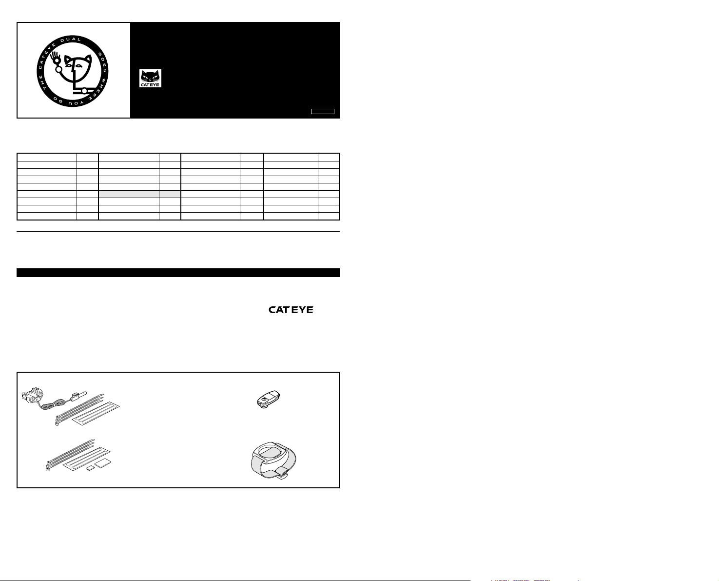
Bracket Sensor Kit Wheel Magnet
Attachment Kit Wrist Band
Page 2
E
A. Selected Function
B. Mode Symbol
C. Scale Symbol
D. Mode Button
E. Contacts
F. AC Button
Fig.1
Fig.2-1
Fig.2-2
Fig.2-3
Fig.2-4
Fig.3-1
Fig.3-2
Fig.3-3
INSTRUCTION MANUAL
1
A
B
MADE IN JAPAN
C
D
E
F
AC
6
1. Bracket
2. Wire
3. Sensor
4. Secure Band
OPERATION FEATURES AND DISPLAY FUNCTIONS
• Mode Button
The mode display changes in the order shown in fig.1 whenever this button is pressed.
• AC Button
When this button is pressed, all the data stored in memory (Total Distance, Scale Symbol, Wheel Circumference and 24-hour Clock Time) will be erased.
Note: This button should only be pressed before initial operation or when irregular display of
information appears.
Current Speed
The current speed is displayed in the Current Speed mode. The speed scales (km/h and mile/
h) are displayed alternatively each time the Mode Button is kept pressed in this mode.
Trip Distance
The distance of each trip is measured and displayed. The Trip Distance can be reset to zero
when the Mode Button is kept pressed in the Trip Distance mode.
Total Distance (Odometer)
The Total Distance is continuously measured, accumulated and displayed. When 10,000
mile(km) is reached, the Odometer will return to zero and counting begins anew.
Note: The Odometer cannot be reset.
24-hour Clock
The current time is displayed as a 24-hour clock. The Clock Time can be reset when the Mode
Button is kept pressed in this mode.
MAIN UNIT PREPARATION
L
User shall make the following setting and the cyclocomputer can be used properly.
• First, measure the wheel circumference L of your bike (Fig.2-1)
Adjust tire pressure and then put a mark on the tire tread. Ride the bike one full wheel
revolution. Mark the ground at the start and end of one revolution and then measure the
distance between the two marks. This measure is your actual wheel circumference. Alternatively, the "Setting Values Cross Reference Table" can tell you an approximate wheel
circumference according to tire size.
• Setting the Speed Scale (mile/h or km/h) (Fig.2-2)
When the AC Button is pressed, all displays will illuminate and then the "km/h" appears.
"km/h" and "mile/h" are displayed alternatively each time the Mode Button is pressed. Select the speed scale desired and keep the Mode Button pressed to complete the setting.
• Setting the Wheel Circumference (Fig.2-3.4)
(Fig.2-3) will blink after speed scale is set. Press the Mode Button to select the first two
digits between 10 and 22 as desired. Keep the Mode Button pressed and the (Fig.2-4) will
blink. Press the Mode Button select a number between 0 and 9 as desired. Keep the Mode
Button pressed to complete the setting.
• Setting the 24-hour Clock (Fig.3-1.2.3)
Select the 24-hour Clock Mode. Keep the Mode Button pressed and the hour will blink.
Press the Mode Button to set a desired hour-time. Keep the Mode Button pressed to complete the hour-time setting. Repeats to complete the setting of 10 minute and minute digits.
5
2
5. Magnet
6. Wrist Band
7. Wire Securing Tape
3
4
7
bracket
lever
magnet
sensor
marking line
spoke
Fig.4
Fig.5
fork
marking line
MOUNTING TO BIKE
Mounting the Main Unit (Fig.4)
Slide the main unit onto the bracket from front until it clicks into position. To remove the main unit, pull the main unit forward while depressing the lever on the
bracket.
Mounting to Bike (Fig.5 to 12)
•The spokes must run correctly through the inside of the magnet as in Fig. 5.
•Attach the sensor on the right fork. (Fig.6) Adjust the position and clearance as follows:
1.Align the center of the magnet and the marking line of the sensor. (Fig.7)
2.A 2mm clearance shall be kept between the sensor and the magnet. (Fig.8)
• Test: Mount the main unit on the bracket. Spin the front wheel to make sure the Current
Speed is displayed. If Current Speed does not display, adjust the position of sensor.
• Secure the sensor in position with a secure band. (Fig.9) Insert the front end of the wire clip
into the slot of the sensor. Pull the wire clip until it is tight and cut off the excess.
•Wind the wire around the outer cable to reach the handlebar as shown in fig.10 and clamp
the wire in position with the wire securing tape.
Note: Keep a loose length of the wire so that it will not hinder handlebar operation.
•Attach the bracket close to the handle stem. (Fig.11)
•Secure the bracket in position by putting secure bands on the grooves of the bracket. Pull
the wire clips until it is tight and cut off the excess. (Fig.12)
HOW TO USE THE DUAL AS A WRIST WATCH
The Dual can be converted to a wrist watch by using with the wrist band.
Fig.6
•Press the main unit onto the ring of the wrist band. (Fig.13-1)
• To remove the main unit, turn the main unit to the left or to the right. (Fig.13-2)
MAINTENANCE/PRECAUTIONS
• Do not leave the main unit exposed to direct sunlight when it is not in use. Do not disas-
center of magnet
magnet
Fig.9
wire securing
tape
Fig.11
secure band
Fig.13-1
Fig.13-2
Fig.7
2 mm
Fig.8
secure band
bracket
ring of the
wrist band
sensor
Fig.10
Fig.12
semble the main unit, sensor and magnet.
•Do not pay too much attention to your computer's function while cycling! Keep your eyes on
the road situation and give due consideration to traffic safety.
• Do not knock the main unit with other objects.
fork
• Check the relative position of sensor and magnet periodically.
• For cleaning, use neutral detergent on soft cloth and wipe off later with dry cloth. Do not
apply paint thinner, benzine or alcohol which may damage the surface.
• The main unit and the battery should be disposed separately. To remove the battery, use a
knife or the like to cut the ditch in a circle on the bottom of the main unit and then take out
the battery.
The following situations do not indicate malfunction of the cyclocomputer.
Check the following before taking to repair.
* When current speed does not appear, short-circuit the contact on the back with
metal. The unit will function normally if the speed display appears.
Trouble The entire liquid crystal screen is dark and unusual display is seen where it shall
not be.
It returns to normal state by leaving it in the shade. No adverse effect on data.
Trouble Display response is slow.
It returns to normal state when temperature rises.
Trouble Incorrect data appears.
Press the AC Button and reset the cyclocomputer.
Trouble Current Speed does not appear
Is the distance between sensor and magnet too great?
Are the marking lines of the sensor and the center of magnet aligned?
Refer to "Mounting to Bike" and re-adjusts correctly.
SPECIFICATIONS
Display Functions Display Range Minimum Display Unit
Current Speed 0.0(3.0) - 62.5mile/h [0.0(4.0) - 105.5km/h]0.1mile/h [km/h]
Trip Distance 0.00 - 99.99mile [km] 0.01mile [km]
Total Distance 0.0 - 999.9mile [km] 0.1mile [km]
(Odometer) 1000 - 9999mile [km] 1mile [km]
24-hour Clock 0:00' - 23:59' 1'
Applicable Cycle Sizes 100 cm - 229 cm Initial value: 203 cm
The length of the wire 70 cm
Battery Life approx. 7 years *In case the unit is used as a cyclocomputer
Dimension 1-25/32" x 1-25/32" x 9/16" (45 x 45 x 14 mm)
Weight 0.65 oz (18.5 g)
100.0 - 999.9mile [km] 0.1mile [km]
with an average of 2 hours per day.
* The specifications and design are subject to change without notice.
 Loading...