


(without price)
AP-60R
JUNE.1999
ELECTRONIC KEYBOARD
INDEX

CONTENTS |
|
Safety Notice ...................................................................................... |
1 |
Specifications .................................................................................... |
2 |
Block Diagram ................................................................................... |
3 |
PCB Layout ........................................................................................ |
4 |
Disassembly Instructions ................................................................. |
5 |
Circuit Description ............................................................................ |
8 |
Print Circuit Board ........................................................................... |
10 |
Troubleshooting .............................................................................. |
17 |
Wiring Diagram ................................................................................ |
19 |
Exploded View ................................................................................. |
20 |
Parts List .......................................................................................... |
21 |
Schematic Diagrams ....................................................................... |
25 |
SAFETY NOTICE
CAUTION!
Danger of explosion if battery is incorrectly replaced. Replace only with the same of equivalent type recommended by the appliance manufacturer.Discard used batteries according to manufacturer's instructions.
— 1 —
|
SPECIFICATIONS |
||
GENERAL |
|
|
|
Number of keys |
88 |
|
|
Polyphonic: |
32-note |
|
|
Preset tones: |
72, Tone, Tempo, Layer, Auto-Harmonize |
||
Key transpose: |
±12 semitone |
|
|
Effects: |
10, Reverb (1, 2, 3), Chorus, Tremolo, Phase Shifter, Organ Speaker, Enhancer, |
||
|
Flanger, Loudness |
|
|
Demo tunes: |
12 |
|
|
Memory: |
Number of Songs: |
2 |
|
|
System: |
|
Real-time recording |
|
Memory Capacity: |
Approximately 4,900 notes total |
|
|
Memory Backup Battery: |
Built-in lithium battery |
|
|
|
|
Battery Life: Approximately 5 years |
Pedals: |
Soft, Sostenuto, Damper |
|
|
Tuning control: |
440Hz ±50 cents |
|
|
Built-In Speakers: |
16 cm dia. x 2 + 5 cm dia. x 2 (Output: approx. 30 W + 30 W) |
||
MIDI: |
16-channel, multi-timbral reception |
||
Terminals: |
PHONES 1 and 2, MIDI (IN/OUT/THRU), LINE OUT L and R (Output Imped- |
||
|
ance: 1.1 KΩ; Output Voltage: 3.5 V, RMS, max.), LINE IN R and L (Input Im- |
||
|
pedance: 32 KΩ, Input sensitivity: 200 mV) |
||
Power source: |
120V (for Taiwan, Brazil, Mexico, USA, Canada), |
||
|
220V, 230V and 240V (for other countries) |
||
Power consumption: |
91W (with 120V AC), 97W (with 220V, 230V and 240V AC) |
||
Dimensions (HWD): |
Without stand: |
219 × 1376 × 592 mm (8-5/8 × 54-3/16 × 23-5/16 inches) |
|
|
With stand: |
850 × 1376 × 592 mm (33-1/2 × 54-3/16 × 23-5/16 inches) |
|
Weight: |
Without stand: |
53.0 kg (117.0 lbs) |
|
|
With stand: |
66.0 kg (145.7 lbs) |
|
— 2 —
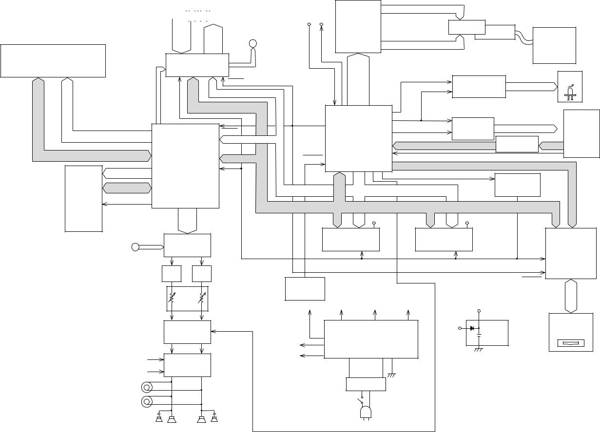
BLOCK DIAGRAM
|
|
Keyboard |
MIDI |
LCD Driver |
SEG1 ~ SEG40 |
|||||||||||
|
|
|
|
|
|
|
|
|
|
|
|
|
|
|||
|
|
|
|
|
|
|
|
|
|
|
|
|
|
|
||
|
|
|
|
|
|
|
|
|
|
|
|
|
|
IN OUT |
|
|
|
|
|
|
|
|
|
|
|
|
|
|
|
|
|
|
|
|
|
SI0 ~ |
|
|
|
SED1278F2A |
|
|
|
|
LCD |
|
|
|
|
|
|
|
|
SI10 |
KC0 |
|
|
|
|
|
|
|
|
CFL |
|
|
CFL Driver |
||
|
|
FI0 ~ |
~ |
|
|
LSI601 |
|
|
|
|
|
|
|
|
|||
|
|
A |
|
COM1 ~ COM7, COM9 ~ COM16 |
|
|
|
|
|
||||||||
|
|
FI10 |
KC7 |
|
|
|
|
|
TE-CFL5-IMI |
||||||||
ROM |
|
|
DOUT |
|
|
|
|
||||||||||
|
|
|
|
|
|
|
|
|
|
|
|
|
|||||
|
Key Controller |
|
|
DB4 |
|
|
|
|
|
|
|
Q601, Q602 |
|||||
MX23C6410MC12CA10B |
|
|
LRCKO |
|
|
|
|
|
|
|
|
||||||
|
TC190C020AF-001 |
|
|
|
|
|
|
|
|
|
|
|
|||||
LSI2 (64Mbit) |
|
|
|
~DB7 |
|
|
|
|
|
|
|
|
|
|
|||
|
LSI6 |
|
|
|
|
|
|
|
|
|
|
|
|
|
|||
|
SYOB |
|
|
|
|
|
LEDCK, LEDCL |
|
|
|
|
|
LEDs |
||||
|
|
|
RESB |
|
CONT, |
|
S-Register |
|
|
|
|
||||||
|
|
|
|
|
|
|
|
|
L1 ~ L46 |
|
|
||||||
|
WOKI |
HWR |
|
|
|
|
LRS, |
|
|
|
NJV 3718L, NJU3716L |
|
|
||||
|
BOK |
|
A1 ~ A4 |
|
|
LR/W |
|
|
|
|
IC301, IC302 |
|
|
|
|
|
|
|
SORP |
|
|
|
|
LE |
|
|
|
|
|
|
|
|
|
|
|
|
RD, |
D0 ~ D15 |
|
|
|
|
|
|
|
|
|
|
|
|
|||
|
|
|
|
|
|
|
|
|
|
|
|
|
|
|
|||
|
|
|
|
|
|
|
|
|
|
|
|
|
|
|
|
|
|
|
|
|
|
|
|
|
CPU |
|
LSDT |
|
|
S-Register |
|
KC0 ~ KC5 |
|
|
|
|
|
|
|
|
PBO |
|
|
|
|
NJU3716L |
|
|
|
||||
|
|
|
|
RESB |
|
|
|
|
|
|
|
|
Buttons |
||||
RA0 ~ RA21 |
|
|
HD6433048SA 62F |
SWCK |
|
|
IC303 |
|
|
|
SI0~SI15 |
||||||
|
|
A0 ~ A3 |
|
|
|
TC74HC257AP |
|
||||||||||
|
|
|
|
|
|
|
KI0 ~ KI7 |
|
|||||||||
|
|
DSP |
|
|
|
|
LSI9 |
|
|
|
|
IC304, IC305 |
|
|
|||
RD0 ~ RD15 |
|
|
|
|
|
|
NMI |
|
|
|
|
|
|
|
|
||
|
|
D8 ~ D15 |
RESET |
|
|
|
|
|
|
|
|
|
|
|
|||
Working |
|
HG51B155FD |
|
|
|
|
|
|
|
TEND, DREQ, CS2, CS3, B1-5 |
|
|
|||||
EA0 ~ EA14 |
|
|
RD, |
|
|
|
|
1RD, 1HWR, 1LWR |
|
Chip Selector |
|
|
|||||
RAM |
|
LSI3 |
|
HWR |
|
|
|
|
|
|
|
|
|
|
|||
ED0 ~ ED7 |
|
|
|
|
|
|
|
|
|
TC74HC08 |
|
|
|||||
|
|
|
|
|
|
A0 ~ A19 |
|
|
|
|
|
||||||
|
|
|
|
|
|
|
|
|
|
IC9 |
|
|
|||||
TC55257 |
ECEB, EOEB |
|
|
|
|
|
|
|
|
|
|
|
|||||
|
|
|
|
|
|
|
|
|
|
|
|
|
|
|
|
||
DFL-70L |
|
|
|
|
|
|
|
|
|
|
|
|
|
|
|
|
|
EWEB |
|
|
|
|
|
D0 ~ D15 |
|
|
|
|
|
|
|
|
|||
|
|
|
|
|
|
|
|
|
|
|
|
|
|
||||
LSI4 |
|
|
|
|
|
D0 |
VBR |
|
|
D8 |
|
VBR |
|
|
|
D8 |
|
|
|
|
|
|
~ |
|
|
~ |
|
|
|
|
~ |
|
|||
|
|
|
|
|
D7 |
|
|
D15 |
|
RD,HWR, |
|
|
D15 |
|
|||
(256Kbit) |
|
|
|
|
|
|
|
|
|
|
|
|
|
||||
|
|
|
|
|
RAM1 |
|
|
|
RAM2 |
|
|
|
|
|
|||
|
|
D/A Converter |
|
|
|
|
|
|
|
|
|
|
|||||
|
|
|
|
TC551001CFL-70L |
|
|
TC551001CFL-70L |
LWR |
|
FDD Controller |
|||||||
|
A |
PD63200GS |
|
|
LSI7 (1Mbit) |
|
|
LSI8 (1Mbit) |
HWR |
|
|||||||
|
|
IC3 |
|
|
|
|
LWR, RD |
|
|
|
HWR, RD |
|
|
RD |
HD63266F |
||
|
|
|
|
|
|
|
|
|
|
|
|
|
|
|
|||
|
|
LPF |
LPF |
|
|
|
|
|
|
|
|
|
|
|
|
|
LSI5 |
|
|
|
|
|
|
|
|
|
|
|
|
|
|
|
|
||
|
|
(L) |
(R) |
|
Reset IC |
|
|
|
|
|
|
|
|
|
RESET |
|
|
|
|
|
|
|
|
|
|
|
|
|
|
|
|
|
|||
|
|
Main |
|
|
MB3771PF |
|
|
|
|
|
|
|
|
|
|
|
|
|
|
|
|
IC7 |
|
|
|
|
|
|
|
|
|
|
|
|
|
|
|
Volume |
|
|
|
|
|
|
|
|
|
|
|
|
|
||
|
|
|
VDD |
DVCC |
AVFF |
AVCC |
|
|
VBR |
|
|
|
|
|
|||
|
|
|
|
|
|
|
|
|
|
|
|
||||||
|
|
MIX Amp |
MUTE |
|
Power Supply Circuit |
|
VDD |
Back up |
|
|
3.5" FDD Unit |
||||||
|
|
IC410 |
|
|
|
|
Power |
|
|
DF354HO64C |
|||||||
|
|
|
|
|
|
|
|
|
|
|
|
|
|
|
|||
|
|
NJM2068D |
|
VCC |
|
IC403 ~ IC406 |
|
|
CR2032 |
|
|
|
|
||||
|
|
|
|
|
|
|
|
|
|
|
|
|
|
||||
|
VCC |
Power Amp. |
|
VFF |
|
|
|
|
|
|
|
|
|
|
|
|
|
|
|
|
|
|
|
|
|
|
|
|
|
|
|
|
|||
|
VFF |
STK4152MK2 |
|
|
|
|
|
|
|
|
|
|
|
|
|
|
|
|
IC407 |
|
|
|
|
|
|
|
|
|
|
|
|
|
|
|
|
|
HP( 2) |
|
|
|
|
|
TE660-IMI |
|
|
|
|
|
|
|
|
|
|
|
|
|
|
|
|
|
|
|
|
|
|
|
|
|
|
|
|
|
|
|
|
|
|
SW401 |
|
|
|
|
|
|
|
|
|
|
|
|
|
|
|
|
|
|
AC INPUT |
|
|
|
|
|
|
|
|
||
|
|
(L) |
(R) |
|
|
|
|
|
|
|
|
|
|
|
|
|
|
|
|
Speakers |
|
|
|
|
|
|
|
|
|
|
|
|
|
|
|
|
|
|
|
|
— 3 — |
|
|
|
|
|
|
|
|
|
|
|
|
PCB LAYOUT
PS12
PS3M |
PS2M |
MA1M |
|
|
CN4M |
RHYTHM |
|
|
|
|
|
TONE |
SEQUENCER |
|
|
|
|
|
|
EFFECT |
|
LAYER |
|
|
|
|
|
|
1 |
2 |
3 |
|
LCD1M |
|
CN1M |
|
|
|
MODE |
VOLUME |
4 |
5 |
6 |
CONTRAST |
SPLIT |
CURSOR |
|
|||
|
|
CN5M |
|
|
DISK |
|
|||||
|
|
|
|
|
|
TRANSPOSE |
|
|
|||
|
|
|
|
|
|
MUSICAL INFORMATION SYSTEM |
|
|
TUNE/MIDI |
|
|
|
|
ORMAL / VARIATION / SYNCHRO / |
|
|
|
|
|
REGISTRATION |
|
|
|
POWER |
|
INTRO FILL-IN FILL-IN |
ENDING |
|
|
|
|
|
CN2M |
|
|
ON |
|
CN6M |
START/STOP |
TEMPO |
|
|
16 CHANNEL MIXER |
|
|
TOUCH |
|
OFF |
|
|
|
|
|
CN3M |
|
|
RESPONSE |
|
|
|
|
|
|
|
|
|
|
|
2HD/2DD FLOPPY DISK DRIVE |
STEREO SAMPLING |
|
KY1M |
|
|
|
|
|
|
KY2M |
|
|
KY3M |
|
PS4M |
|
|
|
|
|
|
|
|
|
|
|
PCB |
JCM660 |
Components |
|
|
|
Main PCB |
MA1M |
CPU, DSP, Sound Source ROM Working storage |
|
|
RAM, Effect RAM Reset IC, DAC, Filter, Key |
|
|
controller, Power amp, Power supply circuit |
|
|
|
Jack PCBs |
PS2M |
LINE IN/OUT jack, MIDI jacks |
|
|
|
|
PS3M |
Phone jacks |
|
|
|
|
PS4M |
Power indicator |
|
|
|
Console PCBs |
CN1M,CN2M |
Tone, Registration, Sequencer, Cursor, Demo |
|
|
|
|
CN3M |
CHANNEL buttons (CH1 to CH16) |
|
|
|
|
CN4M,CN5M,CN6M |
Mode, Volume, Rhythm, Select, Tempo |
|
|
|
LCD PCB |
LCD1M |
LCD driver, CFL drever |
|
|
|
Power PCB |
JCM431-PS12 |
Fuse, Noise filter |
|
|
|
— 4 —
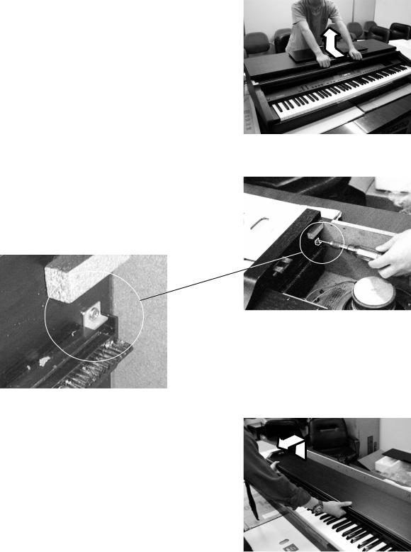
DISASSEMBLY INSTRUCTIONS
1. Removal of top board
1-1. Remove 8 screws affixing the top board on the back. 1-2. Slide the top board forward and remove it from the main
unit.
2. Removal of keyboard cover
2-1. Lift up the keyboard cover full open position.
2-2. Unscrew the L-shaped stopper metal located on the inner left corner.
2-3. Lift up the keyboard cover gear from the opening where stopper metal is fixed, then remove the keyboard cover.
— 5 —
3. Removal of console panel
3-1. Remove 6 screws of the console panel.
3-2. Disconnect connector CC,CD,CE on PCB MA1M, connector CG,CK on PCB PS2M.
3-3. Lift the console panel and turn it over and remove the power switch, which is affixed by 2 screws. Then remove the side panel.
Caution: Be careful not to scratch the side panels.
Power switch |
Connectors (CG,CK) Connectors (CE,CC,CD) |
Screws
4. Removal of front cover
4-1. Remove 6 screws from the front end of the lower case. 4-2. Lift the front cover and remove the pilot lamp that is affixed
by 2 screws. Then remove the front cover.
|
screws |
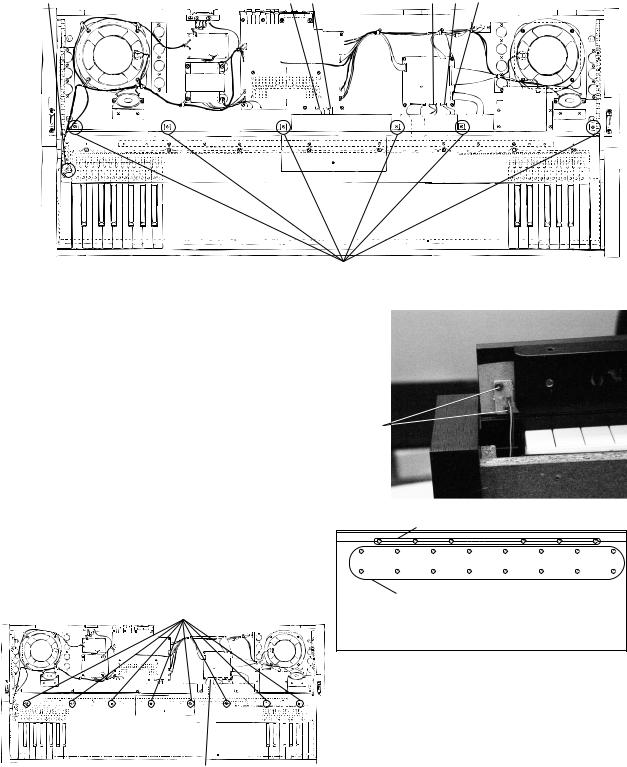
5. Removal of keyboard unit |
|
5-1. Disconnect connector CA on the PCB MA1M. |
|
5-2. Remove 24 screws that affix the keyboard unit |
Front cover screws |
(16 on the bottom of the case and 8 on the |
|
keyboard unit). |
|
5-3. Lift and remove the keyboard unit. |
|
|
Keyboard screws |
Keyboard screws |
|
|
Bottom |
Connector (CA)
— 6 —
6. Removal of keys
6-1. While plying the side partition plastics with tweezers, lift the edge of the key toward front.
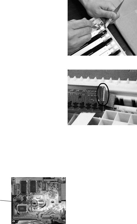
7. Removal of keyboard PCB
7-1. Lay the keyboard so that keyboard PCBs face upward. 7-2. Remove screws on keyboard PCBs (10 screws on PCBs
KY1M and KY3M, 12 screws on KY2M). 7-3. Unsolder the cable.
8. Notes on replacing the main PCB.
A lithium battery is set on the main PCB for memory protection.
When you replace the main PCB, disconnect the jumper to open battery circuit. Since there is no jumper on a new main PCB, be sure to set a jumper.
jumper
— 7 —
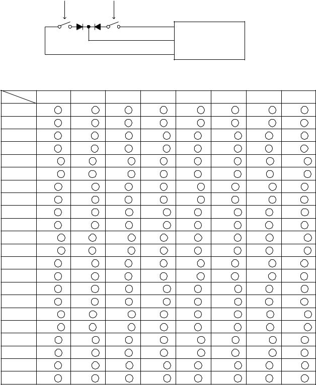
CIRCUIT DESCRIPTION
KEYMATRIX
Second contact First contact
FI
KC LSI
TC190C020AF-001
SI
|
KC0 |
KC1 |
KC2 |
KC3 |
KC4 |
KC5 |
KC6 |
KC7 |
||||||||
FI0 |
A0 |
1 |
A0 # 1 |
B0 |
1 |
C1 |
1 |
C1 # 1 |
D1 |
1 |
D1 # 1 |
E1 |
1 |
|||
SI0 |
A0 |
2 |
A0 # 2 |
B0 |
2 |
C1 |
2 |
C1 # 2 |
D1 |
2 |
D1 # 2 |
E1 |
2 |
|||
EI1 |
F1 |
1 |
F1 # 1 |
G1 |
1 |
G1 # 1 |
A1 |
1 |
A1 # 1 |
B1 |
1 |
C2 |
1 |
|||
SI1 |
F1 |
2 |
F1 # 2 |
G1 |
2 |
G1 # 2 |
A1 |
2 |
A1 # 2 |
B1 |
2 |
C2 |
2 |
|||
FI2 |
C2 # 1 |
D2 |
1 |
D2 # 1 |
E2 |
1 |
F2 |
1 |
F2 # 1 |
G2 1 |
G2 # 1 |
|||||
SI2 |
C2 # 2 |
D2 |
2 |
D2 # 2 |
E2 |
2 |
F2 |
2 |
F2 # 2 |
G2 2 |
G2 # 2 |
|||||
FI3 |
A2 |
1 |
A2 # 1 |
B2 |
1 |
C3 |
1 |
C3 # 1 |
D3 |
1 |
D3 # 1 |
E3 |
1 |
|||
SI3 |
A2 |
2 |
A2 # 2 |
B2 |
2 |
C3 |
2 |
C3 # 2 |
D3 |
2 |
D3 # 2 |
E3 |
2 |
|||
FI4 |
F3 |
1 |
F3 # 1 |
G3 |
1 |
G3 # 1 |
A3 |
1 |
A3 # 1 |
B3 |
1 |
C4 |
1 |
|||
SI4 |
F3 |
2 |
F3 # 2 |
G3 |
2 |
G3 # 2 |
A3 |
2 |
A3 # 2 |
B3 |
2 |
C4 |
2 |
|||
FI5 |
C4 # 1 |
D4 |
1 |
D4 # 1 |
E4 |
1 |
F4 |
1 |
F4 # 1 |
G4 1 |
G4 # 1 |
|||||
SI5 |
C4 # 2 |
D4 |
2 |
D4 # 2 |
E4 |
2 |
F4 |
2 |
F4 # 2 |
G4 2 |
G4 # 2 |
|||||
FI6 |
A4 |
1 |
A4 # 1 |
B4 |
1 |
C5 |
1 |
C5 # 1 |
D5 |
1 |
D5 # 1 |
E5 |
1 |
|||
SI6 |
A4 |
2 |
A4 # 2 |
B4 |
2 |
C5 |
2 |
C5 # 2 |
D5 |
2 |
D5 # 2 |
E5 |
2 |
|||
FI7 |
F5 |
1 |
F5 # 1 |
G5 |
1 |
G5 # 1 |
A5 |
1 |
A5 # 1 |
B5 |
1 |
C6 |
1 |
|||
SI7 |
F5 |
2 |
F5 # 2 |
G5 |
2 |
G5 # 2 |
A5 |
2 |
A5 # 2 |
B5 |
2 |
C6 |
2 |
|||
FI8 |
C6 # 1 |
D6 |
1 |
D6 # 1 |
E6 |
1 |
F6 |
1 |
F6 # 1 |
G6 1 |
G6 # 1 |
|||||
SI8 |
C6 # 2 |
D6 |
2 |
D6 # 2 |
E6 |
2 |
F6 |
2 |
F6 # 2 |
G6 2 |
G6 # 2 |
|||||
FI9 |
A6 |
1 |
A6 # 1 |
B6 |
1 |
C7 |
1 |
C7 # 1 |
D7 |
1 |
D7 # 1 |
E7 |
1 |
|||
SI9 |
A6 |
2 |
A6 # 2 |
B6 |
2 |
C7 |
2 |
C7 # 2 |
D7 |
2 |
D7 # 2 |
E7 |
2 |
|||
FI10 |
F7 |
1 |
F7 # 1 |
G7 |
1 |
G7 # 1 |
A7 |
1 |
A7 # 1 |
B7 |
1 |
C8 |
1 |
|||
SI10 |
F7 |
2 |
F7 # 2 |
G7 |
2 |
G7 # 2 |
A7 |
2 |
A7 # 2 |
B7 |
2 |
C8 |
2 |
|||
— 8 —
BUTTON MATRIX
|
KC0 |
KC1 |
KC2 |
KC3 |
KC4 |
KC5 |
|
|
|
|
|
|
|
|
|
SI0 |
MODE |
BALLAD |
POPS |
SELECT |
GRAND PIANO |
GUT GUITAR |
|
BRIGHT PIANO |
ACOUS GUITAR |
||||||
|
|
|
|
|
|||
SI1 |
AUTO HARMONIZE |
POPS/OLDIES |
16BEAT |
BANK |
E.GRAND PIANO |
HARP |
|
OCTAVE PIANO |
VIOLIN |
||||||
|
|
|
|
|
|||
|
|
|
|
|
|
|
|
SI2 |
ONE TOUCH |
JAZZ/RAGTIME |
ROCK |
A |
E.PIANO 1 |
STRINGS |
|
PRESET |
E.PIANO 2 |
CHOIR |
|||||
|
|
|
|
||||
SI3 |
INTRO |
LATIN/CLASSIC |
JAZZ |
B |
HARPSI CHORD |
BRASS |
|
CLAVI |
NEWAGE |
||||||
|
|
|
|
|
|||
SI4 |
NORMAL/FILL/IN |
– |
EUROPIAN |
C |
VIBRAPHONE |
FLUTE |
|
CELESTA |
CLARINET |
||||||
|
|
|
|
|
|||
SI5 |
VARIATION/ |
OSER/RYTHM |
BALL ROOM |
D |
ACCORDION |
TENOR SAX |
|
FILL-IN |
HONKY-TONK |
TRUMPET |
|||||
|
|
|
|
||||
SI6 |
SYNCRO/ |
– |
LATIN |
E |
PIPE ORGAN |
DRUM SET |
|
ENDING |
E.ORGAN 2 |
BRIGHTNESS |
|||||
|
|
|
|
||||
|
|
|
|
|
|
|
|
SI7 |
STRAT/STOP |
METRONOME |
VARIOUS |
STROE |
DRAWBAR ORGAN |
DRUM SET |
|
E.ORGAN 2 |
BRIGHTNESS |
||||||
|
|
|
|
|
|||
SI8 |
TEMPO DOWN |
4 |
1 |
RECORD |
ch– |
–/NO |
|
|
|
|
|
|
|
|
|
SI9 |
TEMPO UP |
5 |
2 |
PATTERN |
VOLUME + |
+/YES |
|
|
|
|
|
|
|
|
|
SI10 |
– |
6 |
3 |
SONG |
ch+ |
ENTER |
|
|
|
|
|
|
|
|
|
SI11 |
LAYER |
CONTRAST |
EFFECT |
DEMO |
VOLUME– |
TOUCH RESPONS |
|
|
|
|
|
|
|
|
|
SI12 |
SPLIT |
TRANSPOSE |
TRANSPOSE |
DISK |
– |
TUNE/MIDI |
|
DOWN |
UP |
||||||
|
|
|
|
|
|||
|
|
|
|
|
|
|
|
SI13 |
– |
EXTERNAL/ |
ch1 |
ch2 |
ch3 |
ch4 |
|
INTERNAL |
|||||||
|
|
|
|
|
|
||
SI14 |
ch5 |
ch6 |
ch7 |
ch8 |
ch9 |
ch10 |
|
|
|
|
|
|
|
|
|
SI15 |
ch11 |
ch12 |
ch13 |
ch14 |
ch15 |
ch16 |
|
|
|
|
|
|
|
|
— 9 —

PRINT CIRCUIT BOARD
Main PCB JCM660-MA1M
Top View
Bottom View
— 10 —
 Loading...