


50XZ Guide
Carrier 50XZ Guide, 50XZ024, 50XZ030, 50XZ036, 50XZ042 Manual
...
HFATUNG & COOLING
SingMe-Packaged EMectric Heat Pump Unit
with Puron® (R-410A) Refrigerant
%isitx__ _.carrier.com
A Guide to Operating and Maintaining Your
Single-Packaged Electric Heat Pump Unit
NOTE: Read the entire instruction manual be%re starting the
installation.
SAFETY CONSIDERATIONS
Installation and servicing of air:conditioning equipment can be
hazardous &/e to system pressure and electrical components Only
trained and qualified personnel should install, repair, or service
air-conditioning equipment
Untrained personnel can perfom_ basic maintenance fonctions of
cleaning coils and filters. All other operations should be perfbrmed
by tlained service personnel. When working on air-conditioning
equipment, observe precautions in the literature, tags, and labels
attached to the unit, and other safety precautions that may apply.
Follow all safe V codes. Wear safety" glasses and work gloves. Use
quenching cloth fbr unbrazing operations. Have fire extinguisher
available for all brazing operations.
Recognize safety information. This is the saf?ty=alert symbolfi._.
When you see this symbol on the product or in instructions or
manuals, be alert to the potential for personal injury.
Understand the signal words DANGER, WARNfNG, CAU=
TION, and NOTE. Danger identifies the most serious hazards,
which will result in severe personal injury- or death. Warning
indicates a condition d'mt could cause serious personal it{jury," or
death. Caution is used to identify unsafe practices, which would
result in minor personal injury or product and property damage.
NOTE is used to highlight suggestions which will result in
enhanced installation, reliability, or operation.
Note to Installer:This manual should be left with the equipment
user,
Do not store or use gasoline or other flamnmble vapors and
liquids in the vicinity' of this or any other appliance. Failure to
follow this warning could result in fire, serious injury, or
death
Do not use this unit if any part has been under water.
Imntediately call a qualified service technician to inspect the
unit and to replace any part of the cormol system which has
been under water Failure to follow this warning could result
in electrical shock, fire, serious ir_jury, or death.
Before performing recommended maintenance, be sure the
main power s_itch to unit is turned off. Electric shock could
cause serious i11iury or death.
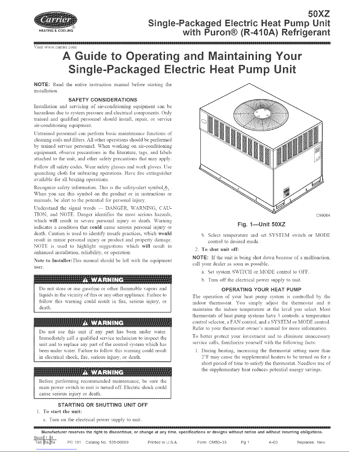
C99064
Fig. 1--Unit 50XZ
b, Select temperature and set SYSTEM switch or MODE
control to desired mode
2 To shut unit off:
NOTE: If the unit is being shut down because of" a malfunction,
call your dealer as soon as possible.
a. Set system SWITCH or MODE control to OFF.
b. Turn off the electrical power supply to unit.
OPERATING YOUR HEAT PUMP
]"he operation of yore heat pump system is controlled by the
indoor them_ostat. Yott simply adjust the them_ostat and it
maintains the indoor temperature at the level you selecL Most
thermostats of heat pump systems have 3 controls: a temperature
conhol selector, a FAN control, and a SYSTEM or MODE control.
Refer to your thermostat owner's manual for more infbmmtion
To better protect your investment and to eliminate unnecessao,-
service calls, familiarize yourself with the _k_llowing facts:
1. During heating, increasing the thermostat setting more than
2°F may cause the supplemental heaters to be turned on for a
short period of time to satisfy the themmstat. Needless use of
the supplementary heat reduces potential energy savings.
STARTING OR SHUTTING UNiT OFF
1, To start the trait:
a. Turn on the electrical po_er supply to unit.
Nanufacturer reserves the r}ght to discontinue, or change at any time, specifications or designs wRhout notice and without incurring oNigations.
PC 101 Catalog No 535-00069 Printed in US.A. Form OM50-33 Pg 1 4-03 Replaces: New
2. Ice or frost tends to fbrm on the coil during winter heating
operatiom Your heat pump is designed to automatically meh
the ice. When in this defrost cycle, it is normal for steam or
fog to rise from the outdoor unit, and for water to drain
from the outside of unit. Do nut be alammd!
Step 1=Cooling Mode
With the SYSTEM o1" MODE control set to (OOL, your heat
pump will run in cooling mode until the indoor temperature is
lowered to the level you have selected. On extremely hut days,
your heat pump will run fbr longer periods at a time and have
shorter "ofF' periods than on moderate days.
Step 2--Heating Mode
With the SYSTEM or MODE control of yore indoor themmstat set
to HEAT, your heat pump will run in heating mode until room
temperature is raised to the level you have selected. Of course,
your heat pump will run for longer periods to maintain a
comf_rtable environment on cooler days and nights than on
moderate ones.
Step a--Supplemental Heat
Yore" heat pump is yore" primary heating source. Your system may
also be equipped with a supplemental }*eating source such as
electric }*eat On cold days and nights, your system will automati=
cally mm on the supplemental }*eat in order to maintain the tevel
of" comfort you }*ave selected.
When yore" heat pump needs additional heat to keep you comfort=
able, your (artier electronic daem_ostat will tm'n on the supple=
mental heat (if equipped) and display the "AUX HT" message
Step 4--Defrost Mode
When yore" heat pomp is providing heat to your home oi"office and
the outdoor temperature &ups below 45_T, moistme may begin to
fieeze on the surfime of" the coil. If allowed to build up, this ice
would impede airt'low across due coil and reduce the amount of
heat absorbed fi'om the outside air. So, to maintain energy=efi_cient
operation, your heat pump has an automatic detiost mode.
The defrost mode starts at a preset time interval of 30 minutes,
although, it may be reset to 60, 90 or 120 minutes. Defrost will
start at the preset time only if the ice is sufficient to interfere with
normal heating operation.
After the ice is mehed from the coil, or after a maximum of 10
minutes in defrost mode, the unit automatically switches back to
normal heating operation.
Do not be alammd if steam or tbg appears at the outdoor unit
during deti'ost mode. Water vapor fi'om the melting ice may
condense into a mist in the cold outside air.
During certain weather conditions such as heavy snow and
fi'eezing rain it is not uncommon for ice to build up on the unit
grille. This is nomaal for these weather conditions. Do not attempt
to remove the ice fiom the unit grille. This condition will not affkct
the proper function of due unit and will clear within a few days.
Step 5--Emergency Heat Node
This allows your supplemental heating source to keep your home
or office warm until your heat pump can be serviced.
MAINTENANCE AND SERVICE
This section discusses maintenance that should be per%tuned by
your dealer and care you, as the owner, may wish to handle for
your new heat pump,
ROUTINE MAINTENAN( E
All routine maintenance should be handled by skilled, experienced
personnel, Your dealer can help you establish a standard proce=
&Ire,
For your safety, keep the unit area clear and flee of combustible
materials, gasoline, and other flammable liquids and vapors.
To assure proper fmactiuning of the unit, flow of condenser air
must not be obstructed from reaching the unit Clearance f?om the
top of the unit is 48 in. ( learance of at least 36 in. is required on
sides except the power entry side (42 in clearance) and the duct
side (12 in. minimum clearance)
MAINTENAN(E AND (ARE FOR THE EQUIPMENT
OWNER
Befbre proceeding with those things you might want to maintain
yourself, please carefidly consider the fbltowing:
m
1. TURN OFF ELECTRI(AL POWER TO YOUR UNIT
BEFORE SERVICING OR PERFORMING MAINTE=
NANCE. ELECTRIC SHOCK (OULD CAUSE SERI=
OUS INJ__ RY OR DEATH.
2. When removing access panels or perfbm_ing maintenance
functions inside your unit, be aware of sharp sheet metal
parts and screws. Although special care is taken to keep
sharp edges to a minimum, be extremely careful when
handling parts or reaching into the unit.
Air Filters
The air filter(s) should be checked at least every 3 or 4 weeks and
changed or cleaned whenever it becomes dirty. Dirty- filters
produce excessive stless on the blower motor and can cause the
motor to overheat and s}mt down.
This unit must have air filters in place befhre it can be operated
These fihers can be located in one of at least two places In many
applications the installer will provide return air filter grilles
mounted on the wail or ceiling of the conditioned stn/cture. In the
instance of tilter grilles, the filters can simply be removed fi'om the
grille and replaced.
The other typical application is an accessory filter rack installed
inside the unit itsel£ The fbllowing information is given to assist
in changing filters used in these internal filter racks.
Table 1 indicates the correct filter size for your unit. Refer to Fig.
2 to access filters installed in the accessory filter rack.
TaMe I--indoor=Air Filter Data
UNIT S_ZE FILTER SIZE
80XZ024°030 20x20xl
50XZ035 20x24xl
80XZ042-060 24x30x1
To replace or inspect filters in accessow- filter rack (See Fig. 2):
1. Remove the filter access panel using a 5/16=in nut driver
2. Remm'e the filter(s) by pulling it out of the unit If the filter(s)
is dirty, clean or replace with a new one.
When installing the new fiher(s), note the direction of the airflow
an'ows on the filter frame.
If you have diklculty locating your air filter(s) or have questions
concerning proper filter maintenance, contact your dealer %r
instructions. When replacing filters, always use the same size and
type of filter that was supplied, originally, by the installer.
 Loading...