

Page 1
51
HEATING & COOLING
Start-Up and Service Instructions
International Series
51CM,GM,ZM.CV,GY
CONTENTS
Page
START-UP ................................................................ 1
SERVICE . . 1
General Notes .. .1
Compressor Replacement 1
SAFETY REMINDERS............................................ 2-5
Preventive Maintenance 2
System Cleaning ... .2
System Flushing .... .2
Physical and Electrical Data
Compressors ... 4
Run Capacitors. .
Thermistors ... 4
Casing Dimensions .. .4
Capillary Data . 5
Capillary Insertion 5
DISASSEMBLY INFORMATION .... 6-17
Model 104's Casing .... 6
Models 304's/404's Casing ... 13
TROUBLESHOOTING GUIDE ... 18
START-UP
Refer to operating instructions in Owner’s Handbook
provided with room air conditioner
General Notes — These Start-Up and Service Instiac
tions are provided to assist the trained and qualified
service technician in repaii ing or replacing components of
Carrier room aii conditioner models produced in 1988,
specifically International Series models (51CM,GM,ZM
Cooling Only, 51CV,GY Cooling and Electiic Heat)
Other Carriei models for prior yeais have separate StartUp and Service publications
IMPORTANT Repairing and servicing ah condi
tioners can be hazardous for untiained individuals
The insti actions printed in this publication are for
properly ttained and qualified Carrier service tech
nicians only
A WARNING
Befoi e working on any air conditioner, be sure to first
disconnect all electric power to the unit to avoid the
possibility of electiical shock and personal injury
...................................
.....................
SERVICE
3
4
1988 Room Air Conditioners
Discharge capacitors beiore disconnecting, by shorting
acioss terminals
Shield coils with cardboard to protect hands against
injury from sharp metal edges when removing compressoi and other components
When disassembling wiring, use numbered stickers to
identify wiie leads and terminals This aids in quick,
accurate reassembly
Check clearances around scroll and housing before
installing fans Before securing fan setscrews, rotate fan
by hand to ensure ample clearance
Refer to Carriei Standard Service Techniques,
Chapters 1 and 2, for information on checking motors,
removing refrigerant, adding oil, evacuating, dehydrating
and charging system Pay particular attention to all saiety
warnings for these procedures
Compressor Replacement — Stand clem ofcom-
ptessoi tetminals when wotking on comptessors With
system imdef piesswe, terminals mar blow Observe
the same safety procedures for rotary compressors as
for reciprocating compressors
When changing compressors
1 Follow all safety codes Reminder use protective
goggles, work gloves and water-soaked quenching
cloth
Shut off electric power and remove wiring irom
compressor
Purge or remove all refrigerant and pressure from
system
Cut suction and discharge lines Use tubing cutter at
convenient location on tubing, near compressor, to
ease reassembly using copper slip couplings
Remove compressor from unit Protect compressor
irom heat and carefully unbraze piping stubs
A CAUTION
Oil vapor in piping stubs can ignite irom torch
flame and cause serious injury Exercise extreme
care when brazing, and keep brazingcloth and fire
extinguisher handy for emergency use
Install oil piping stubs on new compressor and care
fully braze into place
Clean system add or replace liquid line filter drier
Reiei to System Cleaning, and System Flushing
Install new compressor and braze into place with
field-supplied copper slip couplings
9
Connect wiring, replace wire terminals if necessary
Proceed with evacuation, charging and start-up
10
Manufacturer reserves the right to discontinue, or change at any time, specifications or designs without notice and without incurring obligations
Book 1 4
8a
Tab
10a
PC131 Catalog No 535-134 PrintedinUSA Form51-20SS Pgl 7-88 Replaces:New
For replacement Items use Carrier Specified Parts
Page 2
It is much easiei to unsweat a short piece of tubing from
the compressor afte) you have removed the compressoi
irom the unit It follows that you can soldei the oil piping
stub into the new compressor fittings more easily befoie
the eompiessor is put back into the unit
If you choose a good tubing location for cutting the
refrigerant lines initially, the loeation is easily accessible
when making the final joints
SAFETY REMINDERS
1 Cany a file extinguishei in youi tiuck Keep it within
reach when using a torch Check fiie extinguisher
peiiodically to be suie it is fully loaded and iunctional.
2 Know how to handle oxyacetylene equipment safely
Lock the equipment in an upright position in the
truck and at the job site
3 Use dry nitrogen oi carbon dioxide to pressuiize the
system for leak checking Always use a good regulatoi
Be careful not to exceed 150 psig test pressure in the
heimetic eompiessor
4 Weal your safety goggles and gloves when lemoving
refiigeiant from a system
5 Attend your shop safety meetings
Preventive Maintenance
CLEANING — Clean cooling coil and condensei coil
Hold flashlight behind coil to see if all spaces are clear
Use a hooked wire to lemove dirt Dust accumulation
obstructs or reduces airflow and results in loss of capacity Coils may be vacuumed when diy Outdoois, unit can
be brushed with a stiff brush and fins blown out with
compressed aii
Thoroughly clean basepan, motors, fan wheels, other
components and all drain passages Vacuum insulation
Clean all inside painted surfaces with mineral spirits to
remove grease
Clean cabinet and grille Mild detergents reduce elec
trostatic charges on plastic sections of the grille and are
good cleaners Do no! use carbon tetrachloride, solvents
or waxes containing solvents to clean plastic sections
PAINTING — Paint any parts that show evidence of
rust with a good rust-resistant paint
WIRING — Check all wiring for deterioration and all
electrical contacts for tightness and lack of corrosion
LEAKS — Check any connections that show evidence of
oil or leaks When unit is property installed, centered and
leveled (see MOUNTING), check gaskets and wing
panels for possible air leakage
MOUNTING — Make sure unit is secure in window,
level from left to right, and from front to rear according
to installation instructions provided
If used, check compressor mounting springs and re
place if necessary Spt ings tend to lose their tension with
use This could lead to noisy operation
Check fans to ensure they are correctly positioned,
centered in orifice and tight on shaft
CONTROLS — Check unit to ensure all controls ate
functioning correctly and unit operation is normal
Vibrations can cause unwanted noise Check to be sure
no piping is vibrating against any side of unit
System Cleaning — A motor burnout is recognized
by the burnt odor of the refrigerant system When the
motor of a hermetically sealed compressor but ns out, the
insulation of the stator winding forms carbon, water and
acid After burnout, clean refrigerant circuit before a new
motor-compressor is installed installation of a new
capillary and strainer is also recommended when re
placing a compressor after burnout
The system is partially cleaned by back flushing with
relrigerant vapor blown into the suction line and out the
discharge just before connecting the new compressor If
this method is chosen, install a Sporlan C052S (Carrier
No KH41EZ246) lilter drier or equal in the liquid
line, using a capillary tube adapter (Carrier Part No
DEC3680001) An alternate and equally satisfactory
method follows under System Flushing
NOTE Damage to a new compressor caused by failure
to clean the system as recommended is not covered by
the product warranty
System Flushing — Flush with liquid R-22 refrig
erant before the suction line is connected to the new
compressor
1 Clean, flux and solder discharge line to new compressor
NOTE Compressor valves keep relrigerant from
backing out through compressor
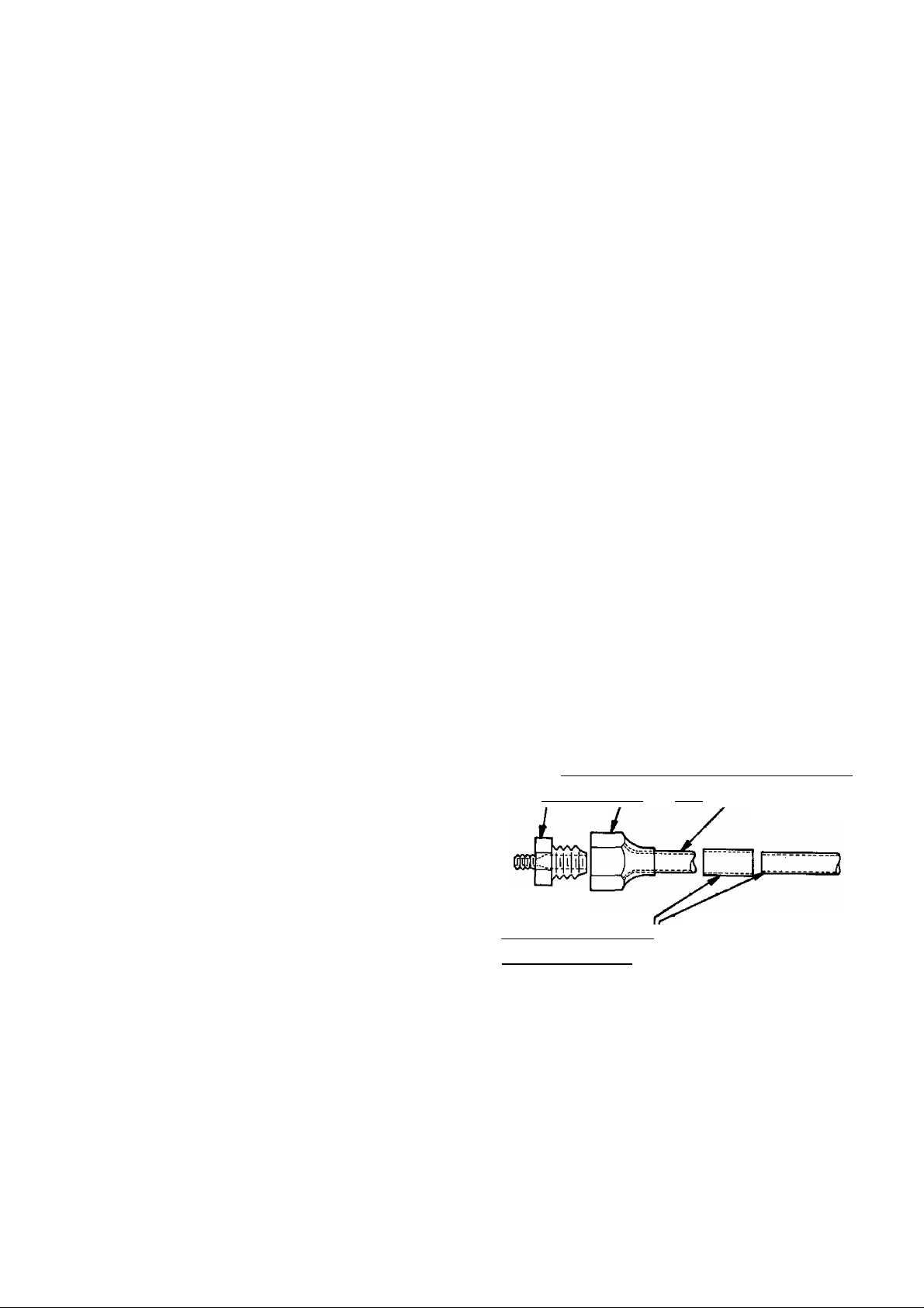
2 Makeal/4-in connection to suction line Forexample
Use a 1/2-in x 1/4-in flare reducing coupling
and a/1/2-in. flare nut and tube (flared) and a
1/2-in sweat coupling||that connects to the system
1 /2-in. suction line. For other size suction lines use
Page 3
proper size fittings to make the connection Connect
1 /4-in fitting to a refrigerant di urn by using chaiging
hose 01 1 /4-in tubing
Cut off the end of the pigtail on the discharge line
Flaie and install a I /4-in stop valve or (preferably) a
charging manifold
Invert drum and charge liquid refrigerant
Open discharge valve and allow to purge slowly until
liquid Freon comes, then close valve
6 Close valve on refrigerant drum and allow refrigerant
to remain in piping at least 15 minutes
7 Open valve on discharge stub and allow refrigerant to
blow out quickly Be careful not to stand in front of
valve when purging Protect hands from refrigerant
burns with cloth
8 Disconnect refrigerant drum and unsolder connection
to suction line
9 Proceed with remainder of installation
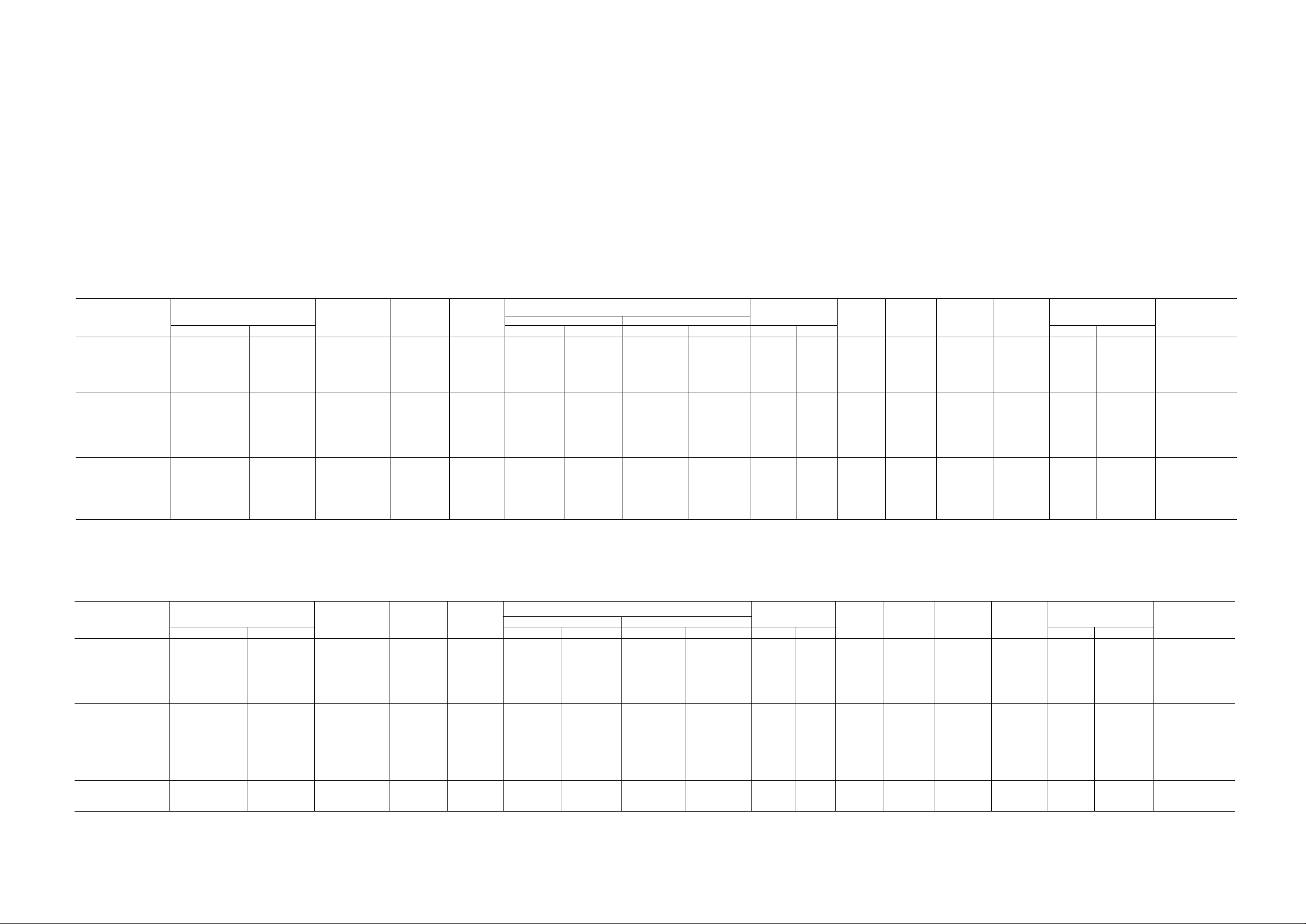
Table 2 — Physical and Electrical Data (Single Phase, 60 Hz) — 1988
MODEL 51
ZMA705101
ZMA705111
ZMA706101
ZMA706103
ZGA706103
ZMA007913
ZGAa07903
ZMA007703
ZMA008101
ZMA008103
ZGA008103
ZMA008703
ZMA009913
ZGA009903
ZMA009703
ZMA009303
ZMB009703
Table 1 — Unit Model Numbers (104, 304, 404)
CASING
104
MODEL 51
CMA109101
CMB112111
CMB112103
CMC012311
CMB012313
CMA012903
CMB012913
CGA012903
CMA012703
CVA212703
CMA115301
CMB115303
CMA118903
CGA118903
CMB118313
CMA118703
CMA115703
CASING
304
MODEL 51
GMA009101
G MA114101
GMA118301
GMA121301
GMA121311
GMA124301
GMA228301
G MA118703
GYA318703
GMA224703
CASING
404
Cool
5,200
7,600
8 800
12,000
12,000
9,000
Cool
12 000
18 000
18,000
CAPACITY
(Btuh)
‘Based on AHAM Standard RAC-1 and ANSI Z234 1
A t — Entering wet-bulb temperature minus leaving wet-bulb temperature based on 67 F room wet-bulb temperature and95F dry-bulb outside air temperature
CAPACITY
(Btuh)
MODEL
51
ZMA705101 5,200
ZMA705111
2MA706101 6,100
ZM,ZGA706103 6,100
ZMA008101 7,600
ZM,ZGA008103
ZMA009303
CMAiogioi
CMB112111
CMB,CGA112103
CMC012311
CMB012313
CMA115301
CGA.CMB115303 15,000/14,800
CMB118313
GMA009101
GMA114101 13,500
GMA118301 18 000/17 700 —
GMA121301 20,500/20 000 —
GMA121311 20,500/20,000 —
GMA124301 23,500/23,000 —
GMA228301 27,500/27,000
DOE — Department of Energy
EER — Energy Efficiency Ratio
FLA — Full Load Amps
Hp — Horsepower
PF — Power Factor
MODEL
51
ZMA007913 7,000
ZGA007903 7,000
ZMA007703 7,000/ 6,800
ZMA009913 9,000
ZGA009903 9,000
ZMA009703 9,000/ 8 750
ZMA008703
ZMB009703
CMA012903 12,000
CMA012703 12,000/11,900
CVA212703 12,000/11,900
CMA115703 15,000/14,800
CMA118703 18,000/17.800
CMA118903 18 000
CMB012913 12,000
CGA012903
CMB118913
CGA118903
G MA118703
GYA318703
GMA224703 24 000/23,500
9,000/ 8,900
11,800/11,700
11,800/11 700
15,000/14,800
18,000/17,800
8,000/ 7,775
8,500/ 8,250 --
18,000/17,500
18,000/17,500
R-22
CHG
Heat
—
—
—
—
—
----
-
—
—
—
—
—
—
—
—
—
—
If conditions vary, wet-bulb At will vary
•Heat
_
—
—
—
—
—
—
_
—
—
—
—
—
—
—
—
—
_
11,300/9,500
—
(oz ± 5 - 0)
155
15 5
15 0 12 1
150 12 1
18 0
18 0
20,0
23 0
30 0
30 0
32 0
32 0
38 0
38 0
32 0
27 0
27 0
40 0 12 1
44 0
39 0
39 0 15 8
40 0
R-22
CHG
{oz ± 5 - 0)
18 5
18 5
160 149
170
170
18 0
18 0
180
29 0 123
32 0 10 6
32 0
29 0
34 0
34 0
22 0 107
22 0 10 7
29 0
29.0 11.1
28 0
28 0 125
36 0 150
WET
BULB
(AtF)
98
98
15 5
155
16.5/16.4 230/208
96
11 2
11 2
109
109
13 1
13 1
14.0
65
86
14 5
14 5
187
VOLTS
115
115
115
115
115
115
115
115
115
230/208
230/208
230/208
230/208
230/208
115
115
230/208
230/208
230/208
230/208
230/208
Table 3 — Physical and Electrical Data (Single Phase, 50 Hz) — 1988
WET
BULB
(AtF)
159
159
21 0
21 0
20 2/20 0
20 2/20 0
20 2/20,0
10 6
10 8
12 9
13 2
11 1
12 5
VOLTS
200
200
240/220
200
200
240/220
240/220
240/220
200
240/220
240/220
240/220
240/220
200
200
200
200
200
240/220
240/220
240/220
Cool
56
56
63
63
81
8 1
4.2/ 4.6
86
120
120
5 9/62
5 9/62
7 5/79
7 5/79
9.2/10.2
7 2
120
8 7/95
10 3/11 0
10 3/11 0
11 3/12 0
15 2/16 0
Cool
44
44
3 8/40
56
56
4 5/47
4 5/47
4 5/47
62
5 6/60
5 6/60
7 8/82
9 5/99
11 9
70
70
11 0
11.0
10 4/110
10 4/11 0
13 7/14 7
NAMEPLATE*
Amps
Heat Cool
_
_
_
_
_
_
_
_
_
_
--
_
_
_
—
_
—
Amps
NAMEPLATE*
Heat Cool
_
_
—
_
_
—
—
-
_
_
_
_
_
_
_
_
15 1/14 0 2250/2190
—
580
580
665
665
845
845
900/ 890
930
1335
1335
1285
1285
1630/1610
1630/1610
2140/2120
750
1320
1950/1920
2220/2165
2220/2165
2550/2500
3350/3290
780
780
780/ 755
1000
1000
950/ 920
995/ 965
995/ 965
1265
1265/1250
1265/1250
1750/1730
2220/2200
2195
1275
1275
2115
2115
2250/2190
3000/2940
Watts
Watts
Heat
_
_
_
_
_
_
_
_
_
_
_
___
_
_
_
—
_
_
_
—
Heat
_
—
—
_
—
_
—
_
_
_
_
_
_
_
_
_
3590/3050
—
FAN
OH
MO
FLA
93
93
93
93
93
93 91
.61
1 40
1 40
1 40
70
70
90
90
.90
1 11
3 10 98
1 00
1 11
1 11
1 60
1 60 Vi 96
FLA
44
44
41
44 89
44
41 'A ,
41
.41 'Ad
60
60
60 Vi;
1 00
1 00
1 60
60
60
1 60
1.60
1 10
1 10
1 50 Va
MO
FAN
TOR
Hp
'/l5
Vts
Vl5
Vl3
V,. 93
Vl2
Vl2
’/.2
V,2
’/l2
%
%
'A 98
V,0
’/6
'A
'A
%
Hp
V20
V20
V20
V.2
y,2
'A
%
'A
'/t2
'A
'A
'A
'A
PF
(%)
90
90
92
92
91
98
93
93
98
98
97
97
93
97
94
94
98
PF
(%)
89
89
86
89
88/89
92/93
92/93
92
96
96
95
97
97
82
82
96
96
90
90
91
EER
(DOE)
90
90
92
9 2
90
90
10.0
9 5 304
90 304
90
9 2/9 1
9 2/9 1 304 T-9
9 2/9 2
9 2/9 2 304 T-12
8.4/8.4 304 T-14
120
102
92
92
9 2
9 2
82
EER
(DOE)
90 Ml-1
90 Mt-1
90 T-4
90
90
80
80
8.0
95 T'11
95 T-10
96 T-10
80 T-13
8 1 304 T-15
82
94
94
85
8.5
80 T-5
80
80 T-9
CASING COMPR
104
104
104
104
104
104
104
304
304
304
404
CASING COMPR
104
404 T-5
___
T-1
T-1
T-2
T-2
T-3
T-3
T-5
T-7
T-8
T-8
T-9
T-12
T-17
H-1
MA-1
T-14
MA-2
T-22
T-23
MI-2
MI-2
T-6
T-6
T-6
T-16
MI-3
Ml-3
MI-4
MI-4
CAPILLARY
Data
C-1
C-1
C-2
C-2 CM
C-3
C-3
C--4
__
C-8
C-9
C-9
C-19
C-19
C-7
C-7
C-11
C-10
C-13
C-14
C-15
C-15
C-20
C-16
Data Insertion
C-5
C-5
C-4
C-6
C-6
C-6
C-6
____
______
C-9
C-10
C-10
C-7
C-11
C-11
C-12
e-12
c-11
c-11
c-17
c-17 CI-3
c-18
Insertion
CI-2
CI-3
CI-1
CI-2
START
THERMISTOR
Z-1
Z-1
START
THERMISTOR
Z-1
Z-1
z-1
DOE ~ Department of Energy
EER — Energy Efficiency Ratio
FLA — Full Load Amps
Hp — Horsepower
PF — Power Factor
‘Based on AHAM Standard RAC-1 and ANSI Z234 1
A t — Entering wet-bulb temperature minus leaving wet-bulb temperature based on 67 F room wet-bulb temperature and95 Fdry-bulboutsideairtemperature
If conditions vary, wet-bulb At will vary
Page 4
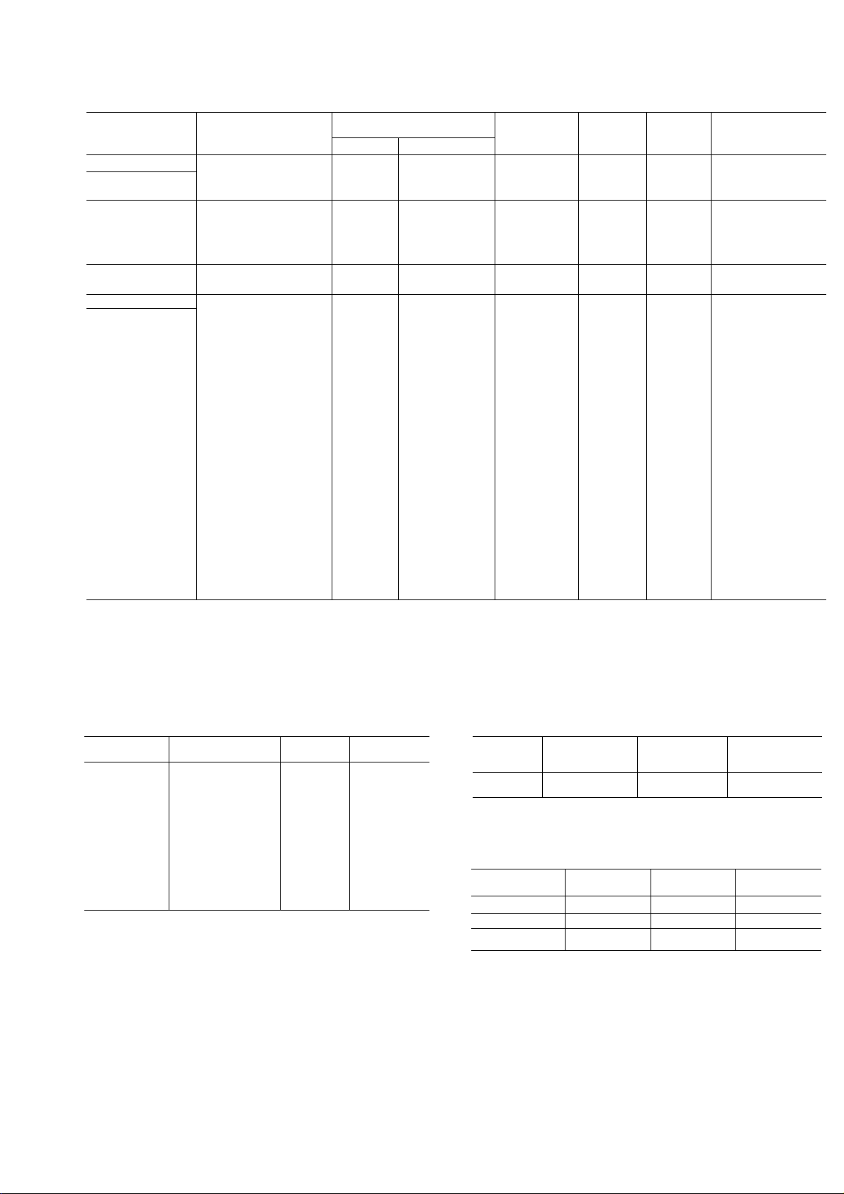
Table 4 — Compressors
KEY NO
Matsushita
MA-1
MA-2
Mitsubishi
MI-1
MI-2
MI-3
MI-4
Tecumseh
H-1
Toshiba
T-1
T-2
T-3
T-4
T-5
T-6
T-7
T-8
T-9
T-10
T-11
T-12
T-13
T-14
T-15
T-16
T-17
T-18
T-19
T-20
T-21
T-22
T-23
T-24
T-25
VENDOR MODEL
NO
2K25S3R236A-6A
2K32S3R236A-6A
RH421SS
RH427SS
RH434SS
NH455NB
RK5513E
ERH62XA3-1K
ERH68XA3-1K
EH88X1-1CU1
PRH94XA4-4K
PRH88XA4-3K
PH112X2-4KU
ERH88XA4-1K
EH120X2-1KU
PH120X2-3KU
PH142X2-4KU
PH142X2-9LU
PH160X2-3LU1
PH180X2-4LU
PH210X3-3LU
PH250X3-4LU
PH250X3-9LU
EH80X1-1CUI
PH200X33-3LTU
PH230X3J-3LTU
PH230X3J-4LTU
PH230X3-4LU
PH250X3-3LU
PH310X3-3MU
PH310X3J-4MTU
PH310X3-4MU
OiL CHARGE (02 ± 1)
Dry
14 5
14 5
10 1
19 2
180
28 7
Recharge
17 3
16 2
25 8
11 8
7 4
7 4
7 4
74
7 4
11 0
7 4
10 6
106
11 0
11 0
14 0
140
20 3
20 3
20 3
74
20 3
20 3
20 3
20 3
20 3
23 7
23 7
23 7
18 3
18 3
18 3
18 3
18 3
21 3
21 3
21 3
\ir\\ TC
125
125
9 1
9 1
67
67
67
6 7
67
9 9 240/220
67
95
95
99
99
126
126
67
183
18 3
183
230/208
230/208
200
200
200
200
115 11 4
115
115
115
240/220
230/208
115 7 7
115
230/208
240/220
200
230/208
240/220
230/208
240/220
200
115
230/208
230/208
240/220
240/220
230/208
230/208
240/220
240/220
RLA LRA
74 42 0
96 52 0
FLA
4 5
56 30 0
73 38 0
97
26 0
47 0
67 0
52 35 0
59 35 0
75
34 20 0
39 25 0
40 23 0
11 6
54
45 26 0
52 27 0
68 38 0
69 36 0
9 1
88
10 2 51 0
—
—
20 0 79 0
—
—
—
—
-
—
41 0
43 0
63 0
33 0
49 0
46 0
41 0
65 0
58 0
46 0
63 0
79 0
83 0
72 0
RUN
CAPACITOR
RC-4
RC-6
RC-12
RC-8
RC-8
RC-7
RC-9
RC-3
RC-3
RC-3
RC-1
RC-1
RC-2
RC-2
RC-5
RC-2
RC-2
RC-2
RC-4
RC-4
RC-6
RC-6
RC-6
RC-9
RC-6
RC-6
RC-6
RC-6
RC-6
RC-6
RC-10
RC-11
FLA “ Full Load Amps
LRA — Locked Rotor Amps
RLA — Rated Load Amps
Table 5 — Run Capacitors
KEY NO
RC-1
RC-2
RC-3
RC-4
RC-5
RC-6
RC-7
RC-8
RC-9
RC-10
RC-11
RC-12
MFD — Microfarad
CARRIER NO
HC98CA016
HC98CA026
HC98CA027
HC98CA036
HC98CA031
HC98CA046
HC98CA050
HC98DA031
HC98CA028
HC98CA062
HC98CA047
HC98DA026
MFD
15/5
25/5
25/7 5 370
35/5
30/5
45/5
50/5
30/5
25/10
60/7 5
45/7 5
25/5
VOLTS
370
370
370
370;
370
370
440
370
370
370
440
Table 6 — Thermistor
KEY NO
Z-1
CARRIER NO
HC95XX006 3M305C20C
VENDOR NO
Table 7 — Casing Dimensions (in.)
CASING
104
304
404
HEIGHT
UVe 20 Vm 17'/e
15S/t6 24Vm
173/i6
WIDTH
26
RESISTANCE
(Ohms)
25
DEPTH
27¥^6
28Vi6
Page 5
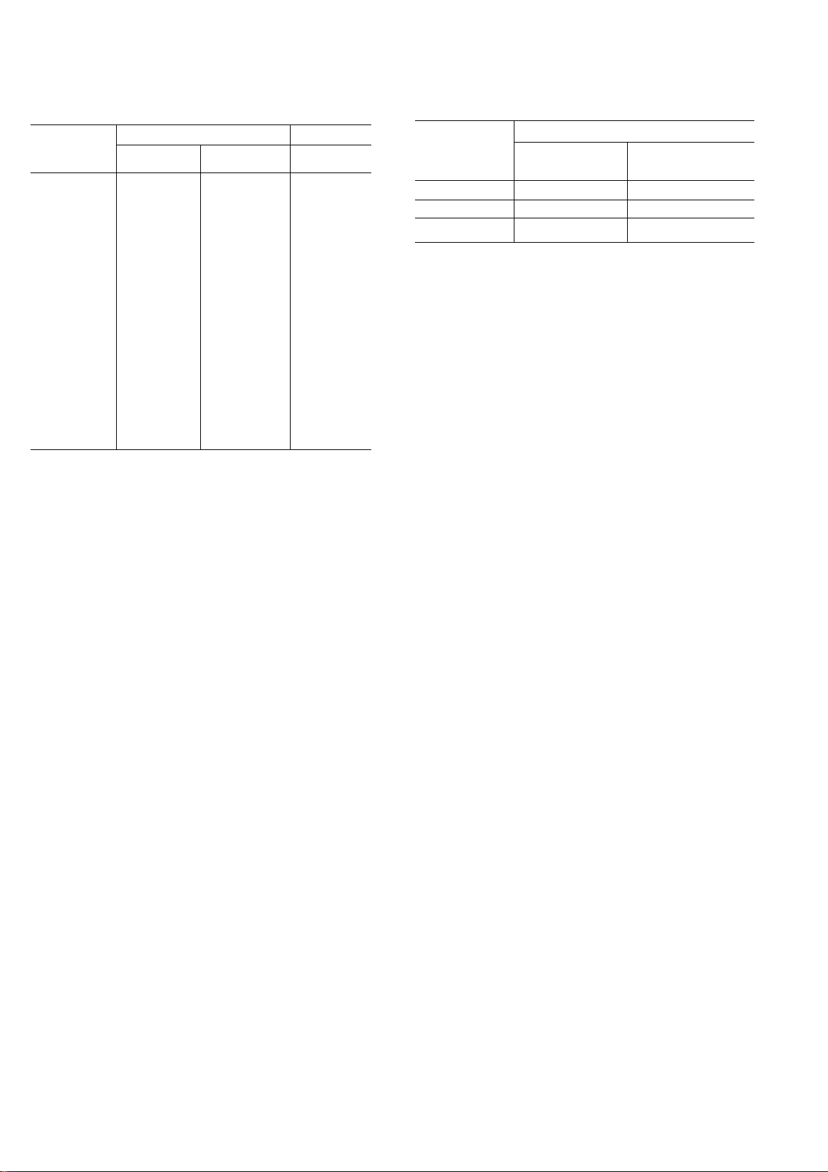
Table 8 — Capillary Data
Table 9 — Capillary Insertion
KEY NO
C-1
C-2 106 055
C-3 106 055
C-4
C-5
C-6(2)
C-7 125 070
C-8
C-9 125 064
C-10 125
C-11
C-12 125
C-13
C-14
C-15(2)
C-16
C-16(2) 106 054
C-16
C-17 (2)
(Injection)
C-18 (2)
(injection)
C-19
C-20 (2)
OD
(± 002)
106 049
106 054
106
106
125 054
125 070
125
125 070
125 054
106 054
106 054
125
080 031
125 070
080 031
125 064
125 064
DIMENSIONS (in.
ID
(± 0003)
049
049
064
064
070
070
Length
(± 25)
30
39
38
42
26
66
34
25
25
35
22
26
26
24
16
46
34
56
36
36
31
18
30
25
NOTE Capillary number follows key number Numbercapillaries
from left to right, facing evaporator inlet, when more than one is
used
KEY NO
CI-1
C1-2
CI-3
DEPTH (In.)
Cond Coil Evap Coil
Conn Tube
(Max) (Min)
Conn Tube
Va
1
Va
1
1
Page 6
DISASSEMBLY INFORMATION
Model 104's Casing
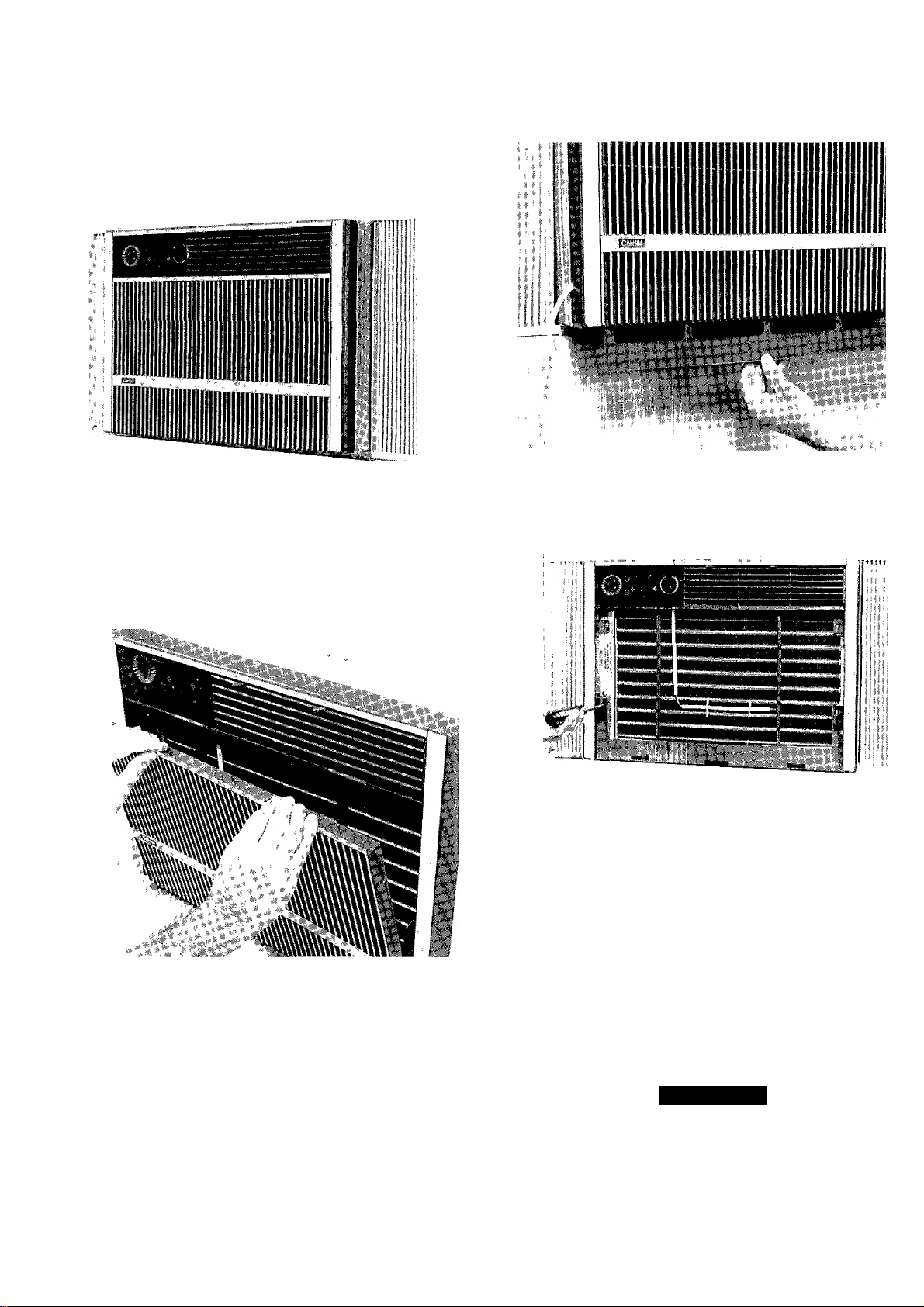
Model 51ZM — The Model 5IZM Room Air Condi-
tioner is leieiied to as the 104 size casing International
Series unit See Fig 1
Fig. 1 — Model 51ZM
1 Grille — Decorative iiont grille insert is removed by
giipping top of insert and pulling outward while lift
ing insert from grille frame See Fig 2
Fig. 3 — Removing Filter
Fig. 2 — Removing Grille Insert
Filter — Filter can be removed without having to
remove grille insert Grasp bottom edge of filter
(located behind grille insert) and gently pull filter
down and slightly toward you See Fig 3 Filter may
be vacuumed, or washed in warm water Shake filter
to remove excess water, dry thoroughly and replace
by sliding filter upward behind front grille until filter
snaps in place
Grille Frame — Grille frame is removed by first
removing 4 screws holding frame to chassis See
Fig 4 Pull top of grille frame outward and lift frame
away from chassis
Fig 4 — Removing Grille Frame Screws
Chassis Security Lock Screw — To slide
chassis out of casing, security screw must first be
loosened Loosen screw and slide screw to unlock
position (forward) When reinstalling chassis in
casing, reverse procedure and tighten screw in lock
position See Fig 5
Chassis — The International Series models have
a slide-out chassis Servicing the chassis is possible
without having to remove rrnit casing from window
See Fig 6 Use the offset in the basepan as a fingergrip handle to slide chassis out of casing
A CAUTION
Coil fins are sharp Use care when removing
chassis from casing to avoid personal injury Do
not use plastic parts for lilting or pulling They
are not structural members of the chassis Lift
using basepan only Chassis is heavy Obtain
assistance for lifting
Page 7
EVAPORATOR
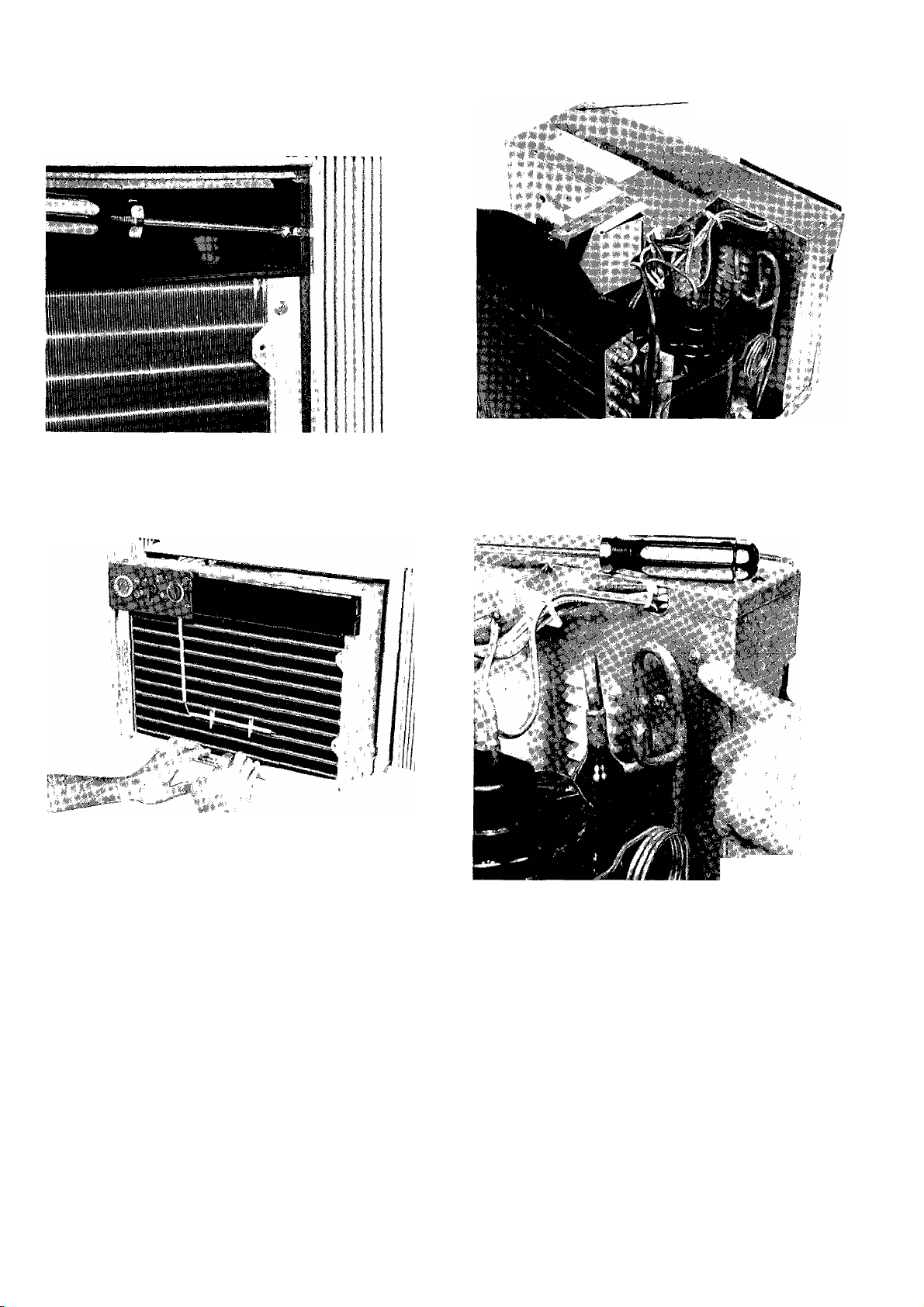
COVER SCREWS (5)
Fig 5 — Unlocking Chassis Security Lock Screw
Fig 6 — Sliding Chassis Out of Casing
Fig. 7 — Evaporator Cover Screws
6 Evaporator Cover — Remove evaporator by
removing 5 sciews as shown in Fig 7
7 Control Box — Conti ol Box is secured with 2
sciews See Fig 8
a Remove sensing bulb from coil See Fig 9
b Remove service cord screw See Fig 9
c Remove control knobs by pulling off See Fig 10
d Remove escutcheon plate
8 Timer — See location of timer in Fig 11
a Remove 2 screws holding timer to control box
b Caiefully pull wires fiom timer terminals being
sure to label or mark each wire for accurate wire
replacement on timer
c To reinstall timei. reverse above procedure
Fig 8 — Control Box Screws
9 Cool-Heat Control — See Cool-Heat Control
location in Fig 11
a Remove 2 sciews holding Cool-Heat Control to
control box
b Carefully pull wires from Cool-Heat Control ter
minals being sure to label or mark each wire for
accurate wire replacement
c Reverse above procedure to reinstall Cool-Heat
Control
10 Fan Cycle Switch — See Fan Cycle Switch loca
tion in Fig 11
a Remove fan cycle switch using screwdriver as
shown in Fig 11
Page 8
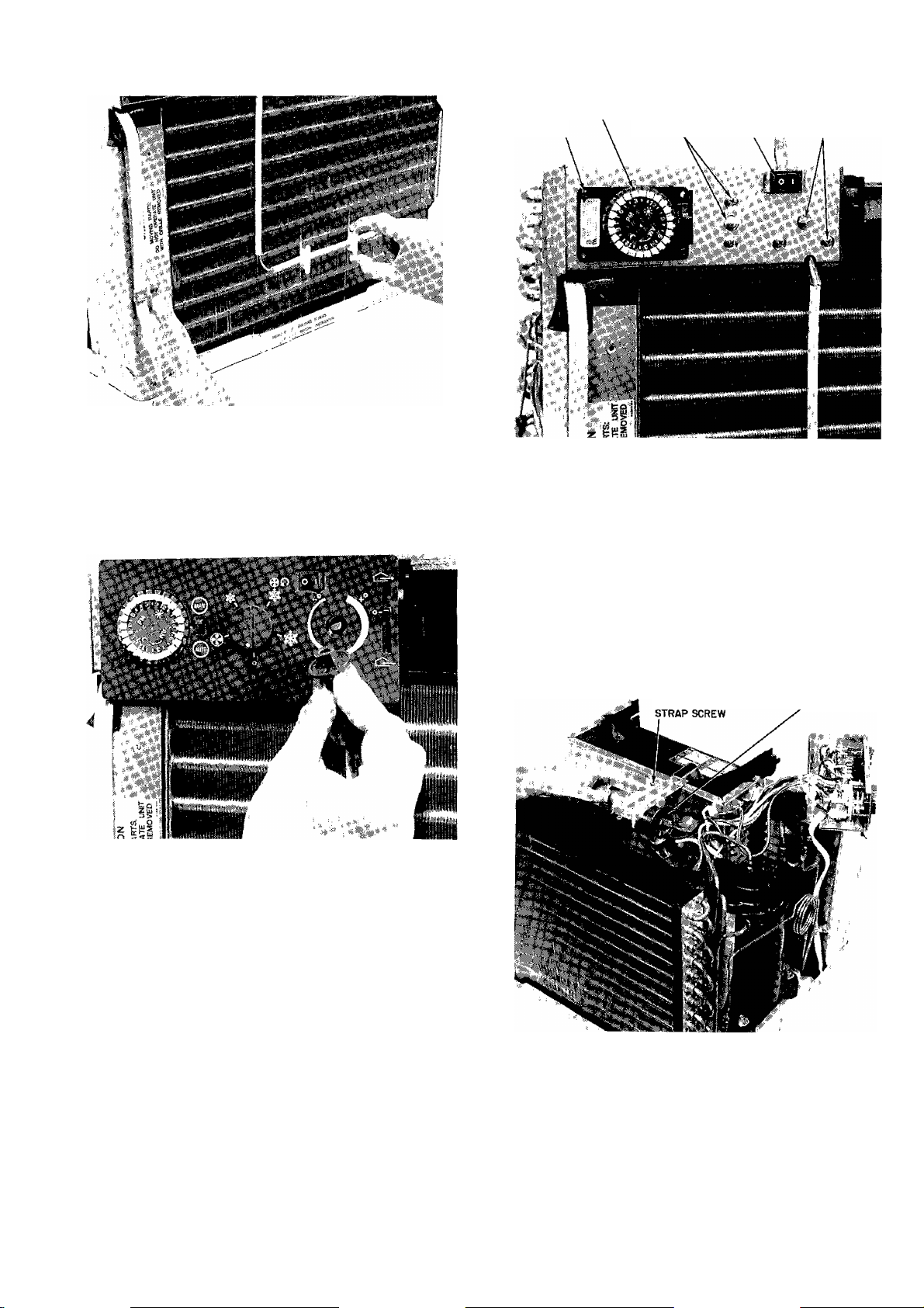
Fig 9 ~ Sensing Bulb and Service Cord Screws
TIMER
REMOVAL
SCREWS (2)
12
TIMER COOL-HEAT FAN
CONTROL AND CYCLE
SCREWS (2) SWITCH
Fig. 11 — Control Locations
Run Capacitor — See Run Capacitor in Fig 12
a Discharge capacitor before disconnecting by
shorting across terminals with a screwdriver
b Remove screw fastening capacitor strap to parti
tion assembly and remove strap
c Carefully pull wires from run capacitor terminal
Mark or label wires for correct reassembly
d Reverse above procedure for reassembly
Fig. 10 — Removing Knobs
b Caieiully pull wires iiom teiminals of fan cycle
switch Label oi mark wires to aid in proper wire
lepla cement
c Reverse above procedure for reinstalling fan cycle
switch
1 Thermostat — See Thermostat location in Fig 11
a Remove 2 screws holding thermostat to control
box
b Carefully pull wires from thermostat terminals
being sure to label or mark wires to aid in correct
wire replacement
c Remove insulating sleeves trom thermostat bulb
d Rerfiove thermostat and bracket itom control
box
e Remove thermostat from bracket by removing 2
screws
f Reverse above procedure to reinstall thermostat
RUN CAPACITOR
Fig. 12 — Run Capacitor
RUN CAPACITOR
13 Fan Motor — See Fan Motor in Fig 13
a Loosen set screw on blower wheel See Fig 14
b Remove clip from condenser ian See Fig 14
c Disconnect fan motor wires from control box and
capacitor
Page 9
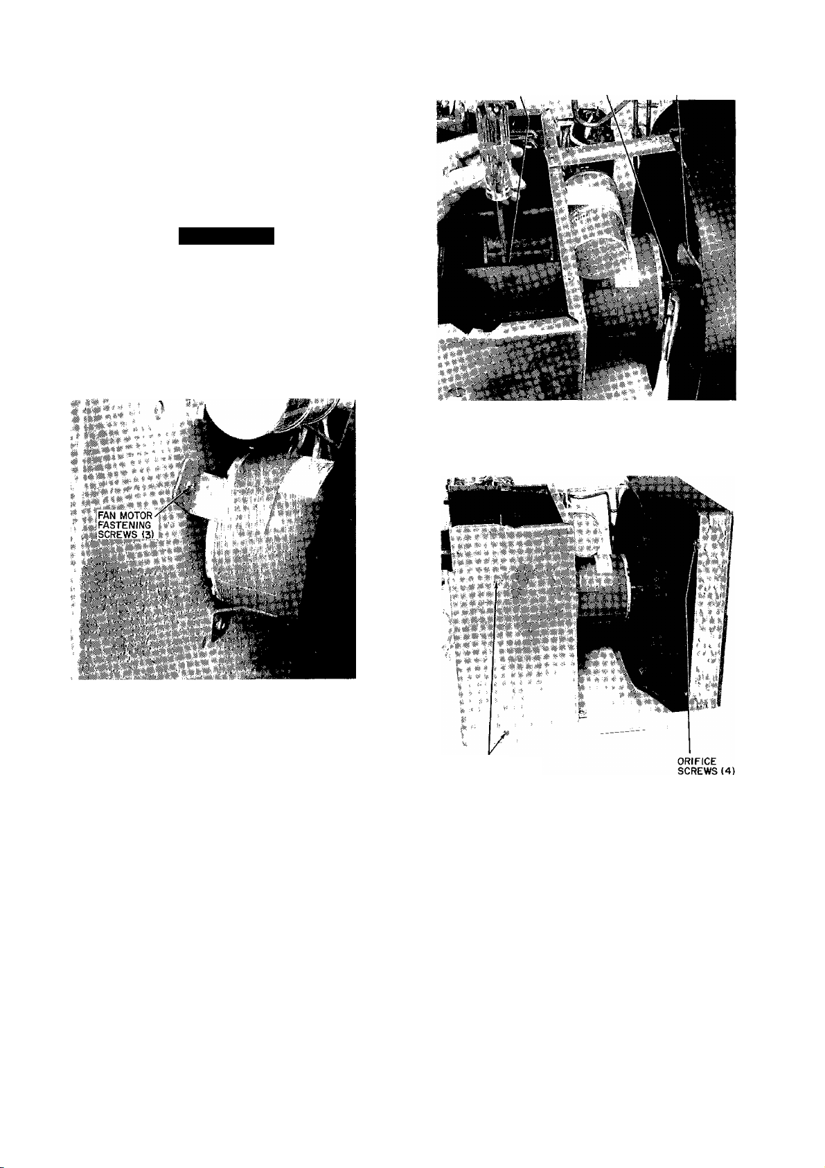
Remove fan motot leads irorn wiie ties Identify
wires foi coirect reassembly
Remove fan motoi ground wiie fiom partition
assembly by lemoving one sciew
Remove 3 screws fastening fan motoi to partition
assembly See Fig 13
Pull fan motor carelully towaid condenser coil
and remove
A CAUTION
Be careful to avoid damaging condensei coil
when pulling and lemoving fan motor
h Reverse above proceduie foi leassembly of fan
motoi
NOTE For proper orientation ol diain holes in re
placement motor, check to be suie motor label is
facing up Foi optimum perfoi mance, position blowei
wheel and propeller fan properly on motoi shaft
SET SCREW LOCATION FAN CLIP
Fig. 14 — Blower Set Screw and
Condenser Fan Clip
CONDENSER FAN
Fig. 13 — Fan Motor
FAN MOTOR LUBRICATION — Fan motor is factory
lubiicated and requires no lubrication undei normal con
ditions foi a period of 5 years The fan motor should be
oiled at the beginning of each cooling season thereafter
li the unit is subjected to heavy usage, dusty atmosphere,
or other abnormal conditions, oil motor at the beginning
of the first cooling season and each cooling season
theieaftei
Fan motois have an oil port on each end ol the motoi
Remove the lubber dust plugs liom oil poits and add 4
diops of SAE 20 oil through each poit Be sure to replace
plugs aftei oiling
14 Condenser Fan—See Condensei Fan in Fig 14
a To aid in leassembly, maik shaft at point wheie
hub and shaft meet
b Remove clip from condensei tan as shown in
Fig 14
c Remove condenser oiifice by lemoving 4 screws
holding condenser orifice to the tube sheet as
shown in Fig 15 and 18
PARTITION
ASSEMBLY SCREWS
Fig 15 — Partition and Orifice Assembly Screws
d Remove 2 sciews in back of unit as shown in
Fig 16 Carefully lift and pull condensei coil
outwaid
e Reverse above procedure foi reassembly
15 Evaporator Blower — See Evaporatoi Blowei in
Fig 14
Remove 3 screws in fiont ol unit as shown in
Fig 17
Remove one screw oncompressoi side (see Fig 16)
which holds evaporator coil tube sheet to partition
assembly
Remove 2 side seiews lastening pai tition assembly
to basepan and paitition assembly to evapoiator
coil tube sheet See Fig 15
Remove 2 back sciews which hold partition
assembly to basepan See Fig 15
Page 10
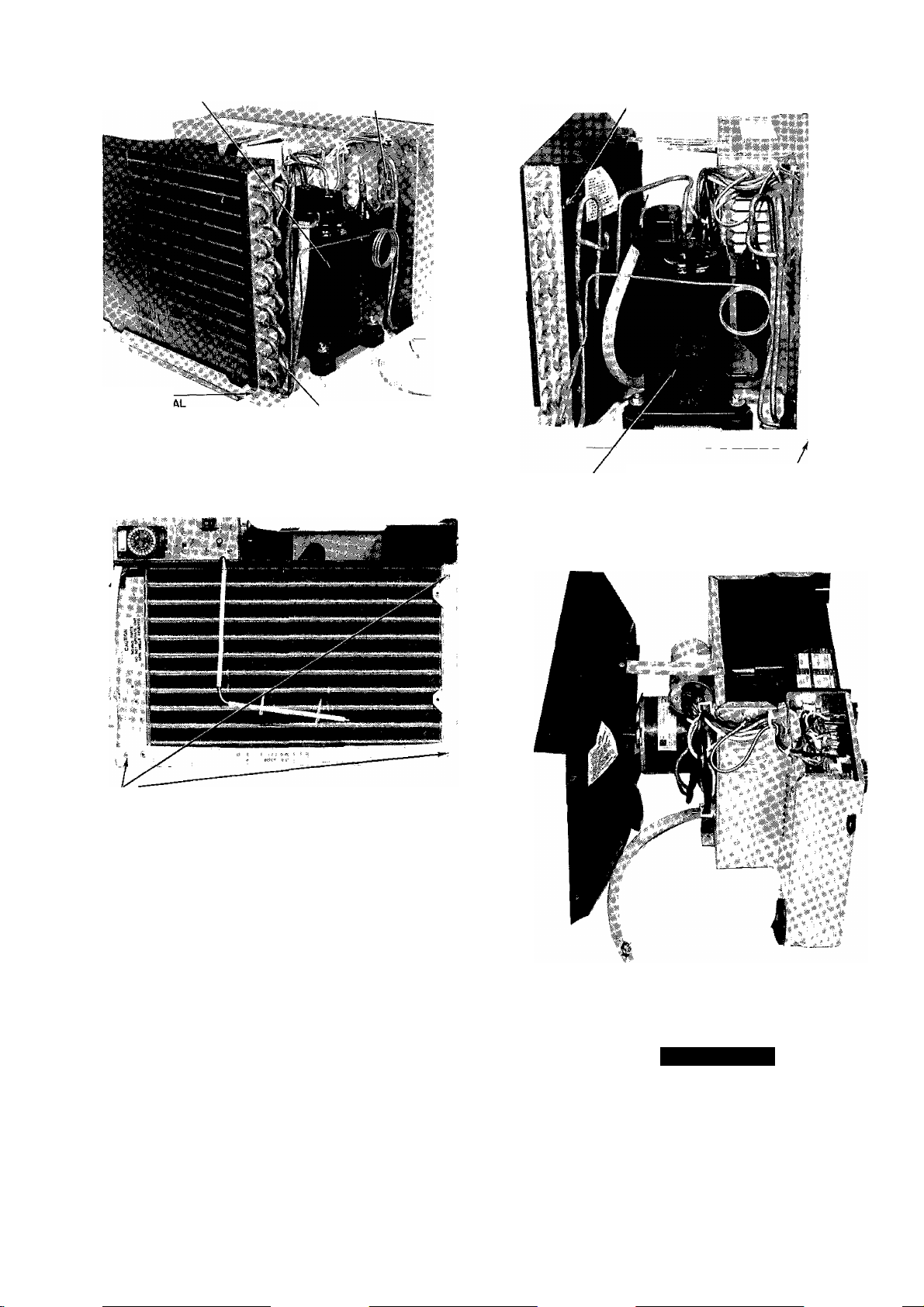
COMPRESSOR
CONDENSER
COIL REMQV
SCREWS (2)
PARTITION ASSEMBLY
REMOVAL SCREW
'condenser COIL
CONDENSER ORIFICE REMOVAL
ÍSCREWS (4)
Fig, 16 — Condenser CoM/Partition Assembly
Screws
PARTITION ASSEMBLY
REMOVAL SCREWS [3Ì
Fig. 17 — Partition Assembly Screws
e Remove screw on compressor side which holds
partition assembly to basepan as shown in Fig 18
f Remove 4 sciews which fasten condensei oiifice
to tube sheet See Fig 15 and 18
g Lift paitition assembly out of unit See Fig 19
When lifting, caiefully grasp secure parts and lift
gently Obtain assistance in lifting if necessary
h Mark shaft at point wheie blowei hub and shaft
meet, to aid in leassembly
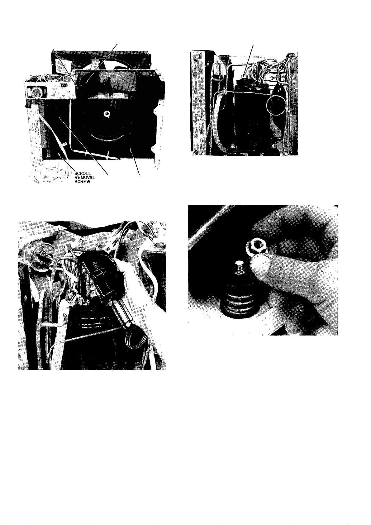
i Remove screw which holds the evaporatoi scioll
to the paitition See Fig 20
j Remove control box See Fig 8 Refei to Conti ol
Box removal diiections
k Pull evaporatoi scroll outwaid
1 Reverse above pioceduie foi leassembly
16 Compressor — See compressoi in Fig 18 Before
lemoving compressoi refer to Service, General Notes
in this publication, and Cariier Standard Service
Techniques Manual, Chapters 1 and 2
PARTITION ASSEMBLY
compressor
REMOVAL SCREW
Fig 18 — Partition Assembly Removal Screws
Fig 19 — Partition Assembly
WARNING
Compìessor terminals may blow with system
undei piessuie Stand cleai of teiminals when
woiking on compiessoi
a Remove compressor teiminal cover See Fig 21
b Disconnect wiies fiom compiessor and oveiload
protectoi teiminals See Fig 22 Identify wires to
ensure coiiect leassembly
10
Page 11
VENT AND
EXHAUST LEVER
EXHAUST DOOR
TERMINALS AND WIRING
VENT
DOOR
Fig 20 — Evaporator Scroll
SCROLL
Fig. 22 — Compressor and Overload Protector
Wires
Fig 23 — Removing Nut from Compressor
Spring Mount (not all models)
Fig 21 — Removing Compressor Terminal Cover
c Replace overload piotectoi if needed
d Disconnect piping Refer to Seivice in this publi
cation being caieful to observe all CAUTIONS
e Remove compiessoi mounting nuts See Fig 23
f Check compiessor mounts It compressoi is
mounted on spn'ngs, remove nuts from mounting
studs See Fig 23 Some mounts also have a
washei Piy off with seiewdiiver Failure to
remove hardware lesults in noisy operation Save
hardware for possible futuie transport of unit It
unit istianspoited, replace haidware on mounting
studs Neglecting this could result in damage to
unit when transported
g Remove compressor carefully Obtain help in
lifting if necessary
h Reverse above procedure lor reassembly
17 Exhaust Door — See Exhaust Door in Fig 20
a Remove metal spring from behind the door
b Pull exhaust door carefully out oi mounting slot
c Reverse above procedure for reassembly
18 Vent Door — See Vent Door in Fig 20
a Remove evaporator scroll as described under
Evaporator Blower
b Remove spring from vent door
c Lift vent door up and pull out
d Reverse above procedure for reassembly
11
Page 12
19 Vent and Exhaust Lever — See Vent and
Exhaust Level in Fig 20
a Remove exhaust dooi as desci ibed under Exhaust
Door
b Rotate levei upward while pushing lever out oi
mounting slot
c Reveise above procedure for leassembly
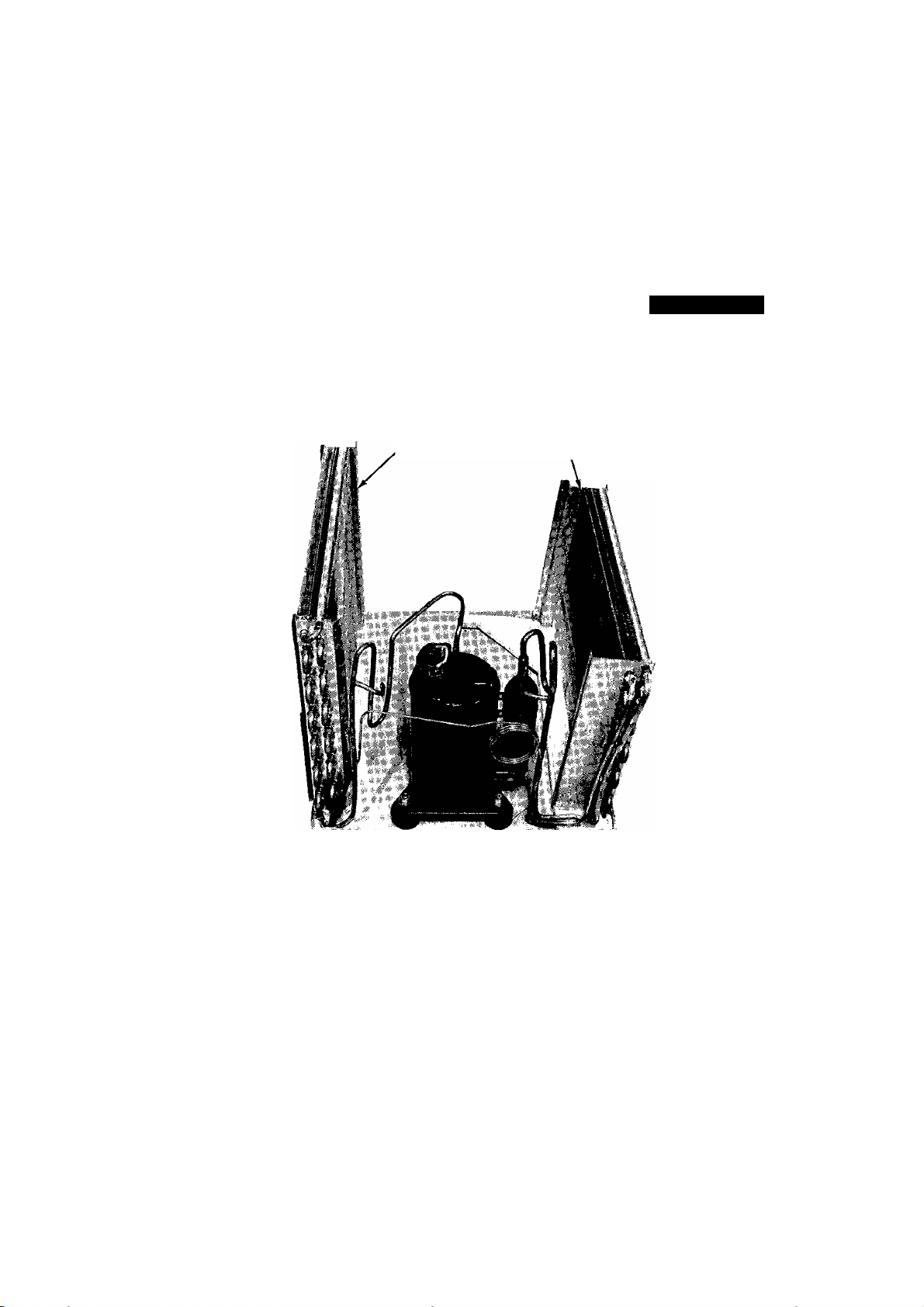
20 Evaporator and Condenser Coils — See
Evaporatoi and Condenser Coils in Fig 24 These
coils have copper tubing The interconnecting tubing
is designed as an integral pait of the coils to make
servicing easier
21 Strainer — The strainer is installed in the inter
connecting tubing between the condenser and the
capillary tube To change the strainer
a Purge and remove all refi igei ant from the system
b Cut tubing one in from capillary tube insertion
point
c Use a thin piece of wire to remove strainer from
tubing
d Insert new strainer into tubing Reassemble with a
field-supplied 1 /4-in copper coupling
22 Test Run Unit — Plug unit into proper power
supply outlet Reiei to operating instructions in
Owner’s Handbook for Comfortable Living Check
all controls for correct operation, then unplug unit
If unit sounds noisy during test-run, it may be
because compressor spring-mount nuts have not yet
been removed See Compressor instructions (16 f)
A WARNING
Moving parts can cause personal injury Be care
ful when test-running unit Do not operate unit
with Iront grille removed
CONDENSER
'COIL
EVAPORATOR
COILi
Fig 24 — Evaporator and Condenser Coiis
12
Page 13
DISASSEMBLY INFORMATION
Models 304's, 404's Casings
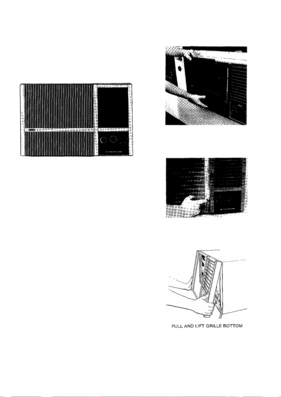
Models 51 C,G — The Model 51C Room Air Condi
tions is referred to as the 304 size casing International
Series unit The Model 51G Room Air Conditioner is
referred to as the 404 size International Series unit Both
are alike in construction and contain identical controls
Fig 25 — Model 51C,G
REMOVE GRILLE INSERT
23 Grille — Decorative front grille insert is removed by
gripping top of insert and pulling outward while lift
ing insert from grille frame See Fig 26
24 Filter — Filter can be removed without having to
remove grille insert Grasp bottom edge of filter
{located behind grille insert) and gently pull filter
down and slightly toward you See Fig 27 Filter
may be vacuumed, or washed in warm water Shake
filter to remove excess water, dry thoroughly and
replace by sliding filter upward behind front grille
until filter snaps in place
25 Grille Frame — Grille Frame is removed by first
removing 1 screw holding frame to chassis See
Fig 26 Pull bottom
OÍ grille frame outward and lift
frame away from chassis
26 Control Box — It is not necessary to slide chassis
out of casing in order to service the control box,
located on right side of unit behind grille irame
Refer to Fig 25 To remove control box
a Remove grille frame Refer to grille and grille
trame instructions and Fig 26
b Carefully pull oii thermostat and cool-heat con
trol knobs
c Remove 2 screws securing escutcheon and remove
escutcheon
d Remove 2 screws securing control box to chassis
e Remove sensing bulb from coil face See Fig 29
f Pull control box straight out of unit carefully
NOTE The control box ground wire interieres with
complete removal of control box If ground wire is
detached, be sure to replace and secure with wire tie
inside control box when servicing is completed
REMOVE 1 SCREW
Fig. 26 — Removing Grille Insert
and Grille Frame
13
Page 14
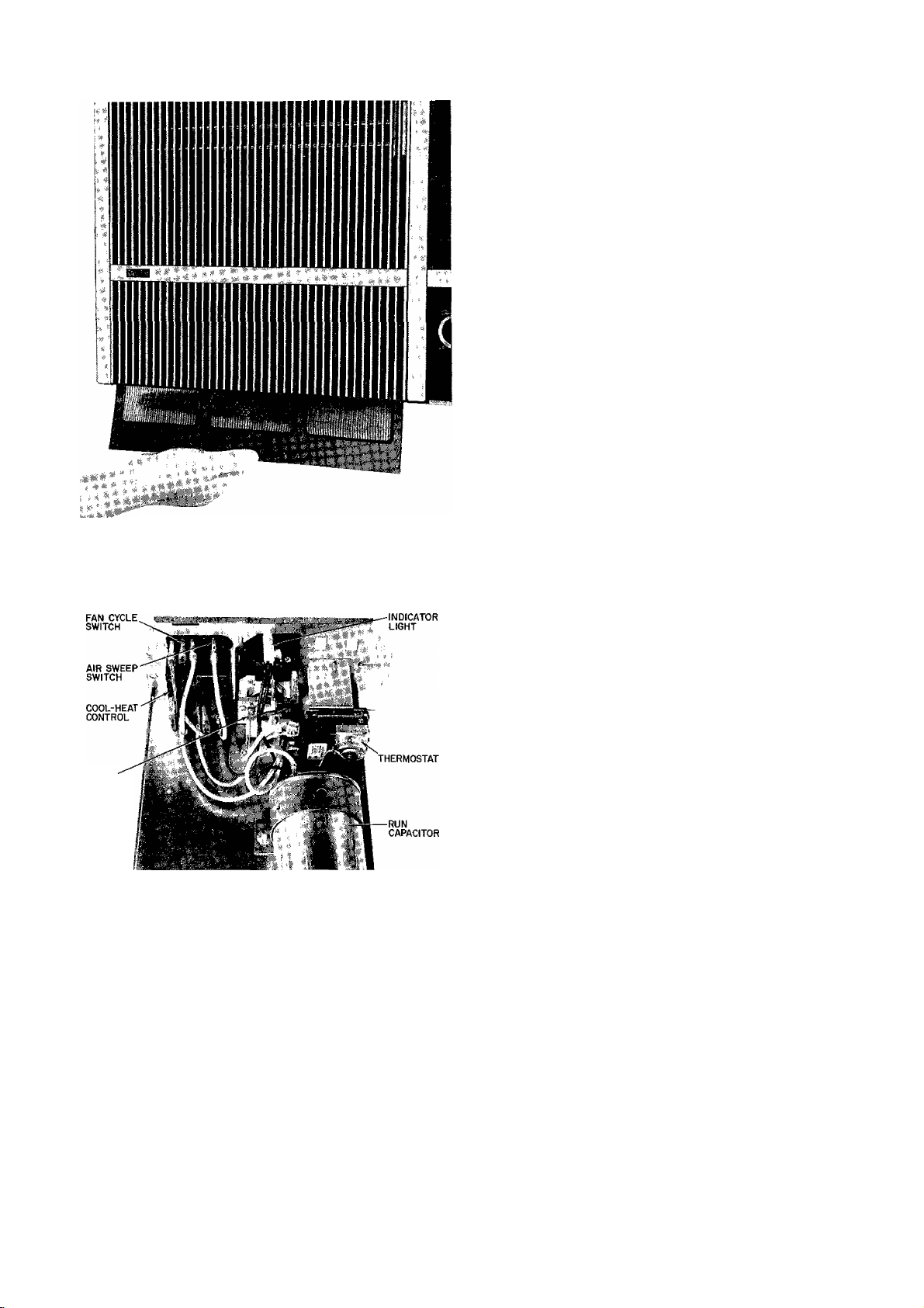
Fig. 27 — Removing Filter
28 Cool-Heat Control — See location ot Cool-Heat
Control in Fig 28
a Slide control box out Refer to control box
instructions
b Remove 2 screws holding cool-heat control to
front of control box
c Carefully pull wires from cool-heat control ter
minals Mark or label wires to aid in reassembly
d Reverse above procedure for reassembly
29 Timer Assembly — See location of Timer
Assembly in Fig 28
a Slide control box out Reier to control box
instructions
b Remove timer cover by squeezing sides and pull
ing cover straight out
c Careiully remove wires from timet assembly
Mark or label wires to aid in reassembly
d Remove 2 screws securing timer and pull timer
through front of control box
e Reverse procedure for reassembly
30 Run Capacitor — See location of Run Capacitor
in Fig 28
a Slide control box out Refer to control box
instructions
b Remove screw fastening capacitor strap to contr ol
box and remove strap
c Carefully pull wires from run capacitor terminals,
marking or labeling wires to aid in reassembly
d Reverse above procedure for reassembly
TIMER
ASSEMBLY
Fig. 28 — Control Box Components
27 Thermostat — Thermostat is a cioss ambient
device Be careful not to damage sensing element
of theimostat when handling See Thermostat
location in Fig 28 To remove
a Slide control box out Refer to contiol box
insti actions
b Remove 2 screws fiom bottom of control box
which fasten thermostat bracket to control box
Some units have a third screw located at front
of box
c Carefully pull wires from thermostat terminals
Mark or label wires to aid in reassembly
d Remove thermostat and bracket from control box
e Detach thermostat from bracket
f Reverse above procedure for reassembly
31 Indicator Light — See location of Indicator Light
in Fig 28
a Slide control box out Refer to control box
instructions
b Remove timer cover by squeezing sides and pull
ing straight out
c Disconnect wires horn indicator light terminal,
marking or labeling wires to aid in reassembly
d Remove light by pulling straight out through
front of control box
e Reverse above procedure lor reassembly
32 Fan Cycle and Air Sweep Switches — See
location of switches in Fig 28
a Slide control box out Refer to Control Box
instructions
b Disconnect wires from switches Mark or label
wires to aid in reassembly
c Push switches out from rear
d To replace switches, insert them through front oi
panel, push in until they snap in place
e Complete reassembly by reversing above
procedure
33 Chassis — The International Series models have
slide-out chassis Servicing the chassis is possible
without having to remove unit casing from window
a Remove fr ont grille frame See Grille instr actions
and Fig 26
b Loosen security lock screw and slide screw to
unlock position (left) See unit installation
instructions
14
Page 15
SENSING
BULB
.'•‘•««»A
Fig. 29 — Sliding Chassis Out of Casing
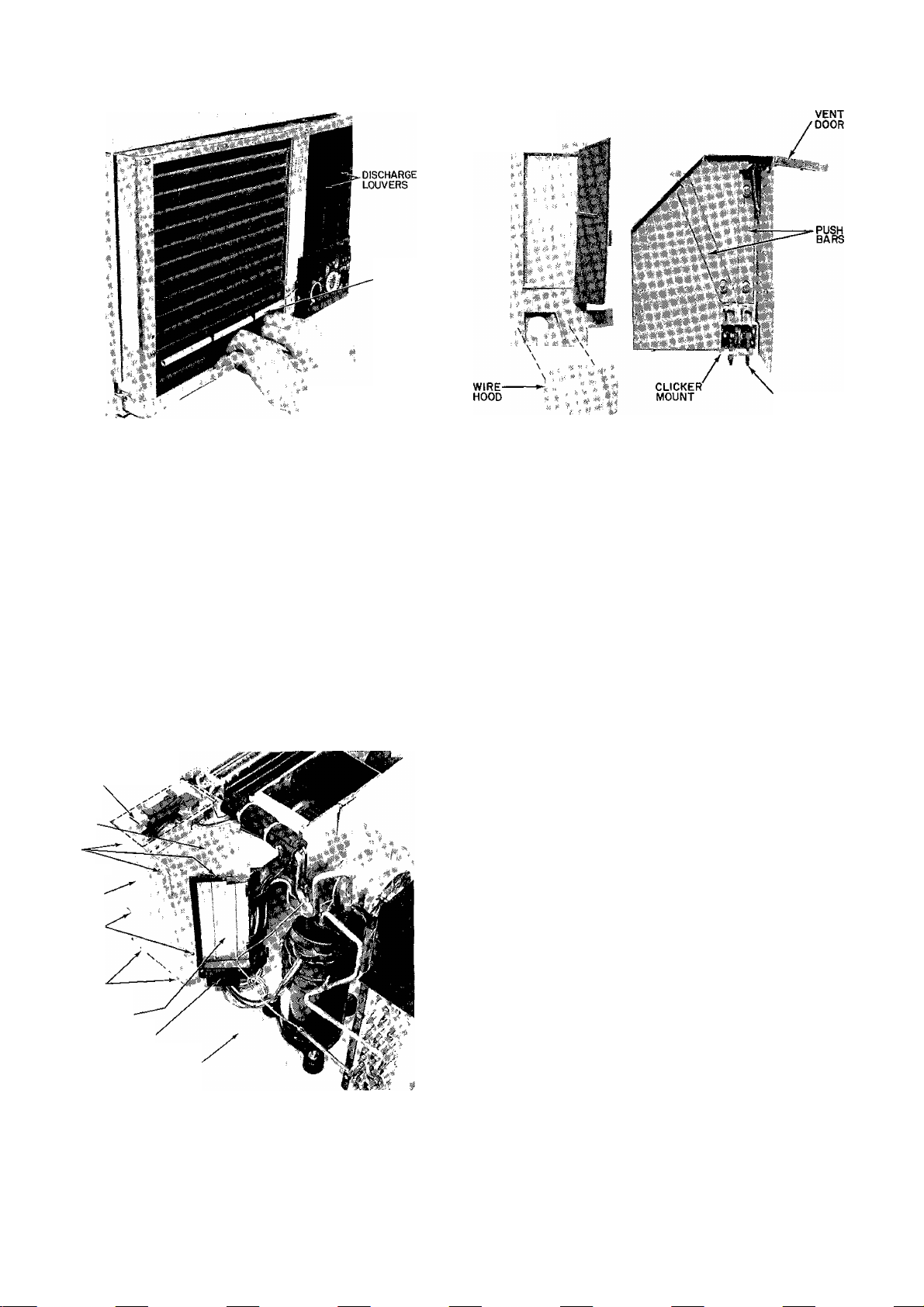
EXHAUST DOOR
FRAME
Fig. 31 — Vent Door/Wire Hood
CLICKER BAR
c Slide chassis out of casing See Fig 29
d Reverse above proceduie to reinstall chassis in
casing, being suie to retain security lock screw
to lock position and tighten
34 Exhaust Door — See location of Exhaust Door
in Fig 30
a Remove chassis fiom casing See Chassis
instructions
b Pull exhaust door away from hinge until it is no
longer trapped by the dooi frame
c Return spring to propei position and lemove
door
d Reveise above proceduie for reassembly
AIR SWEEP
MOTOR COVER
LOCATION (COVER
REMOVED)
UPPER
CONTROL
BOX
UPPER
CONTROL
BOX SCREWS
PARTITION
DISCHARGE.
DECK
SCREWS
PARTITION
SCREWS
EXHAUST DOOR
WIRE HOOD
BASEPAN
Fig 30 — Exhaust Door
35 Vent Door — See location of Vent Dooi in Fig 31
a Remove chassis from casing See Chassis instruc
tions and Fig 29
b Remove conti ol box See Control Box instructions
c Remove dischaige louvers See Air Sweep Mech
anism instructions
NOTE Removal of air sweep motor is not
necessary
d Remove one sciew seeming scioll plate to
basepan
e Remove 3 screws (Fig 30) securing upper conti ol
box to partition
f Remove 2 screws (Fig 30) securing dischaige deck
to paitition
g Remove one screw (Fig 35) securing discharge
deck to scroll plate
h Remove 3 screws (Fig 30 and 33) securing parti
tion to basepan
i Lift partition side and place over basepan flange
t Lift discharge deck assembly and remove from
chassis
k Remove vent dooi spring from deck assembly and
repail or leplace paits as necessaiy
1 Reveise above pioceduie foi leassembly, being
caieful not to damage wires on sheet metal edges
36 Fan Section — See Fan Section in Fig 32
a Remove chassis from casing See Chassis
instructions
b Remove partition top covei by removing 4 screws
c Remove wiie hood by lemoving 2 screws See
Fig 31
d Disconnect fan motor wiies fiom conti ol box
Remove fan motoi leads fiom retaineis Mark or
label wiles to aid in reassembly
e Remove fan motor ground wiie fiom unit
paitition
f Detach condenser orifice by removing 4 screws
which attach condenser orifice to tube sheet
g Remove top gusset by removing 2 sciews Slide
slot filler out
h Remove 2 fan motor clips
i Gently lift fan assembly out of chassis See Fig 32
15
Page 16
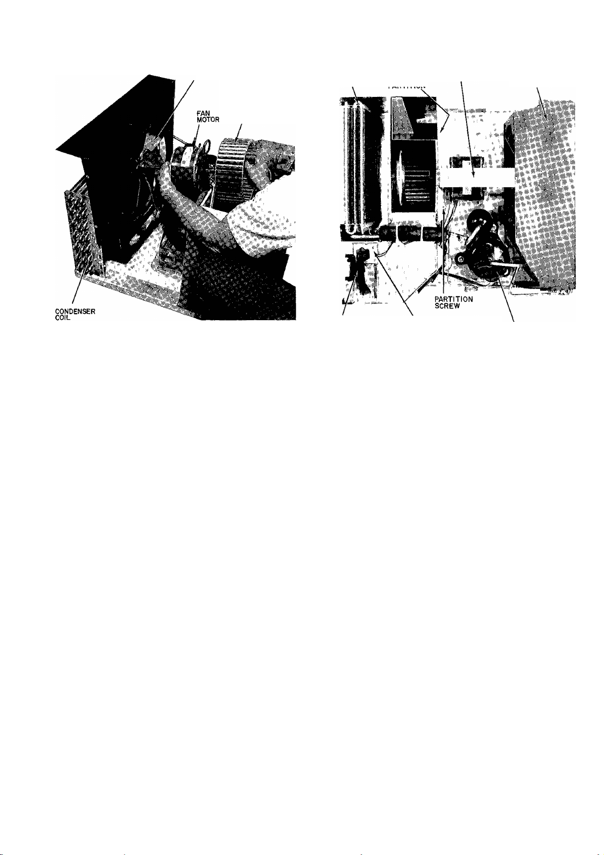
CONDENSER FAN
EVAPORATOR
BLOWER
WHEEL
EVAPORATOR TOP GUSSET
C0|L\ DARTITinM
CONDENSER
ORIFICE
Fig 32 “ Evaporator Fan Section
j Reverse above piocedure tor reassembly
NOTE When replacing fan motor, be sure motor oil
ports are facing up
37 Evaporator Fan—SeeEvapoiatoi FaninFig 32
a Remove fan section Refer to Fan Section
instiuctions
b Mai k shaft at point where fan hub and shait meet,
to aid in reassembly
c Loosen Allen set-sciew which locks evaporator
fan on motor shaft Some units have a spring
metal clip which must be removed
d Remove fan tiom motor shaft
e Fot reassembly, leveise above pioceduie
38 Condenser Fan — See Condenser Fan in Fig 32
a Remove fan section Refei to Fan Section
instructions
b Mark shaft at point where fan hub and shaft meet
toi leassembly
c Remove fan fiom motoi shaft
d Reverse above procedure for leassembly
39 Fan Motor — See Fan Motot in Fig 32
a Remove fan section Refer to Fan Section
instiuctions
b Remove both fans Refei to Evapoiatoi Fan and
Condensei Fan instructions
c Reverse above procedure for reassembly
40 Compressor — See Compressor in Fig 33 Before
removing compressor, refer to Service, General
Notes in this publication, and Carrier Standard
Service Techniques Manual, Chapters 1 and 2
a Remove compressor terminal cover See Fig 21
b Disconnect wires from compressor and overload
protector terminals Mark wires to aid in
reassembly
c Replace overload protector if needed
AIR SWEEP
MECHANISM
AIR SWEEP
MOTOR BRACKET COMPRESSOR
Fig. 33 — Chassis Top View
Disconnect piping Refer to Service in this publL
cation being careful to observe all CAUTIONS
Remove compressor mounting nuts See Fig 23
Remove compressor carefully Obtain help when
lifting if necessary
Reverse above procedure for reassembly
41 Air Sweep Mechanism — See Air Sweep Mech
anism in Fig 33
a Remove chassis from casing Refer to Chassis
instructions and Fig 29
b Remove partition top cover by temoving4 screws
c Remove motor cover by removing 2 screws See
Fig 30
d Remove link assembly by lifting straight up
e Remove spring to disassemble link assembly
f Remove cam from motor shaft
g Remove motor and motor bracket from chassis
by removing 2 screws
h Remove motor from motor bracket by removing
2 screws
i Slide out control box and disconnect air sweep
motor leads Refer to Fan Cycle and Ait Sweep
Switches instruction
j To remove discharge louveis, flex and remove pin
from bottom hole Turn louver and pivot bottom
upwaid to remove from top hole See Fig 29
and 34
k Reverse above procedure for reassembly
42 Evaporator and Condenser Coils — See
Evaporator and Condenser Coils in Fig 32 and 33
These coils have copper tubing and the intei con
necting tubing has been manufactured as an integral
part of the coil to aid in seivicing
a Purge all refrigerant from system Refer to Serv
ice in this publication
b Cut interconnecting tubing and remove evap
orator coil from unit by removing 4 screws
16
Page 17
c Cut interconnecting tubing and lemove 2 screws
securing condenser coil Remove condenser
orifice mounting screws (4)
d Remove condenser coil
e Reverse procedure for reassembly
43 Strainer — Strainer is installed in the interconnect
ing tubing between the condenser and the capillary
tube To change strainer
a Purge and remove all refrigerant from system
b Cut tubing one in horn capillary tube insertion
point
c Use a thin piece of wire to remove strainer from
tubing
d Insert new strainer into tubing Reassemble with a
field-supplied 1/4-in copper coupling
44 Vent and Exhaust Linkage — See Vent and
Exhaust Linkage in Fig 31
a Remove decorative front grille Refer to Grille
instructions and Fig 26
b Remove control box Refer to Control Box in
structions and Fig 25
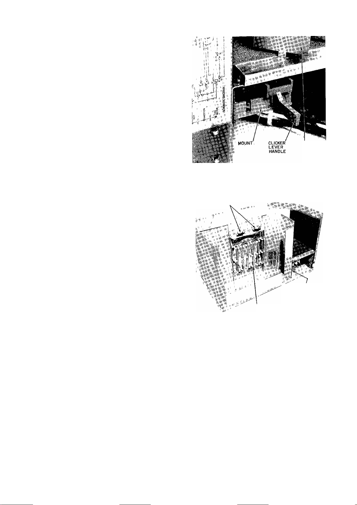
c Remove clicker lever Push up on lever handle
while holding mount down See Fig 34
d To reinstall, push clicker lever straight in through
mount, until it snaps in place
e To remove mount, remove 2 screws Irom mount
and remove from discharge deck
1 To remove push bars, remove screws and dis
assemble from discharge deck See Fig 31
g To reassemble, reverse above procedure
45 Electric Heater Assembly — See Electric
Heater in Fig 35 The electric heater is found only
in the Models 5ICV and 51 GY
a Remove chassis from casing See Chassis instruc
tions and Fig 29
b Remove partition top cover by removing4 screws
c Remove 2 wires Itom heater assembly Mark wires
to aid in reassembly
d Repair or replace limit switches as needed
e Remove heater by removing 2 screws and lifting
straight up
f Reverse above procedure for reassembly
Fig 34 — Vent and Exhaust Linkage
LIMIT SWITCHES
ELECTRIC HEATER
Fig. 35 — Electric Heater Assembly
DISCHARGE
LOUVER
DISCHARGE
DECK SCREW
(NOT VISIBLE)
17
Page 18

TROUBLESHOOTING
NO COOLING OR INSUFFICIENT COOLING
Compressor Does Not Run
OPENING IN POWER CIRCUIT
Control off
Blown fuse
Defective wiring
Defective service cord
Loose electrical connections
Faulty switches, theimostat oi fan
COMPRESSOR POWER SUPPLY OPEN
Loose leads at compiessoi teiminals
Detective motor overload switch
Defective capacitor
Open compressoi windings
Seized compressor
Compressor Runs But Cycles
FAN OPERATING ERRATICALLY
Loose lead at fan motoi
Motor defective or burned out
Outdooi air restricted or leciiculating
OVERCHARGE OR NONCONDENSABLES IN
SYSTEM
RESTRICTED DISCHARGE LINE
CYCLES ON COMPRESSOR OVERLOAD
Defective lun capacitor
Defective compìessor beatings oi valves
Gieatly restricted indoor ait (iced indoor coil)
Low lefrigerant charge
Indooi capillary restricted
Liquid line lestiicted
Compressor hot
Compressor Runs But Insufficient Cooling
COOLING AIR NOT ADEQUATE
Dirty filter 01 coil
Iced evaporator coil (slightly low lefiigerant
chaige)
Defective fan motor
CONDENSER AIR NOT ADEQUATE
Outside air restricted
Dirty coil
Defective Ian motoi
UNIT UNDERSIZE
AIR LEAKAGE
LIQUID LINE SLIGHTLY RESTRICTED
Capillary restricted
COMPRESSOR FLOODING
Unit oveichaiged
SERVICE POINTS
(Check Annually)
1 Clean evaporator and condenser coils Indoois —
Use a hooked wire or bristle brush to lemove dirt
from fins Outdoors — Use compressed air or a
vacuum cleanei
2 Clean basepan and othei painted surfaces
3 Clean all drain passages
4 Clean motor and fans
5 Vacuum clean the insulation
Paint paits that show evidence of lust with a good
lust-resistant paint
Check relrigerant connections foi evidence of
leakage Repair if necessaiy
Check wires lot deteiioiation
8
Check damper contiols
9
Fans should be tight on motoi shaft
10
Run the unit and eliminate any piping vibiation
11
18
Page 19

Page 20

Page 21

Manufacturer reserves the right to discontinue, or change at any time, specifications or designs without notice and without incurring obiigations
Book
Tab
1_\4
8ajl0a
PC131 Catalog No 535-134 PrintedinUSA Form51-20SS Pg 21 7-88 ReplacesiNew
For replacement items use Carrier Specitied Parts
 Loading...