


42CJR018-723
Carrier 42CJR018-723, 42TAR024X-723, 42CJR024-723, 38TAR024X-723, 42TAR018-723 Service Manual
...
SERVICE MANUAL
AIR CONDITIONER
SPLIT WALL TYPE
42CJR024-723 / 38CJR024-723
42CJR018-723 / 38CJR018-723
FILE NO. SVM-05010-2
42TAR024X-723 / 38TAR024X-723
42TAR018-723 / 38TAR018-723
42HNR024-713 / 38HNR024-713
42HNR018-713 / 38HNR018-713
18 Class
(Heat pump model)
24 Class18 Class
(Cooling only model)
Revised Aug, 2005

FILE NO. SVM-05010
CONTENTS
1. SPECIFICATIONS
2. CONSTRUCTION VIEWS
2-1 Indoor Unit (42CJR024-723, 42TAR024X-723, 42TAR018-723)
2-2 Outdoor Unit (42CJR018-723, 42HNR018-713, 42HNR024-713)
2-3 Outdoor Unit (38CJR024-723, 38TAR024X-723, 38TAR018-723, 38HNR024-713)
2-4 Outdoor Unit (38CJR018-723)
2-5 Outdoor Unit (38HNR018-713)
3. WIRING DIAGRAM
3-1 42CJR024-723 / 38CJR024-723, 42TAR024X-723 / 38TAR024X-723
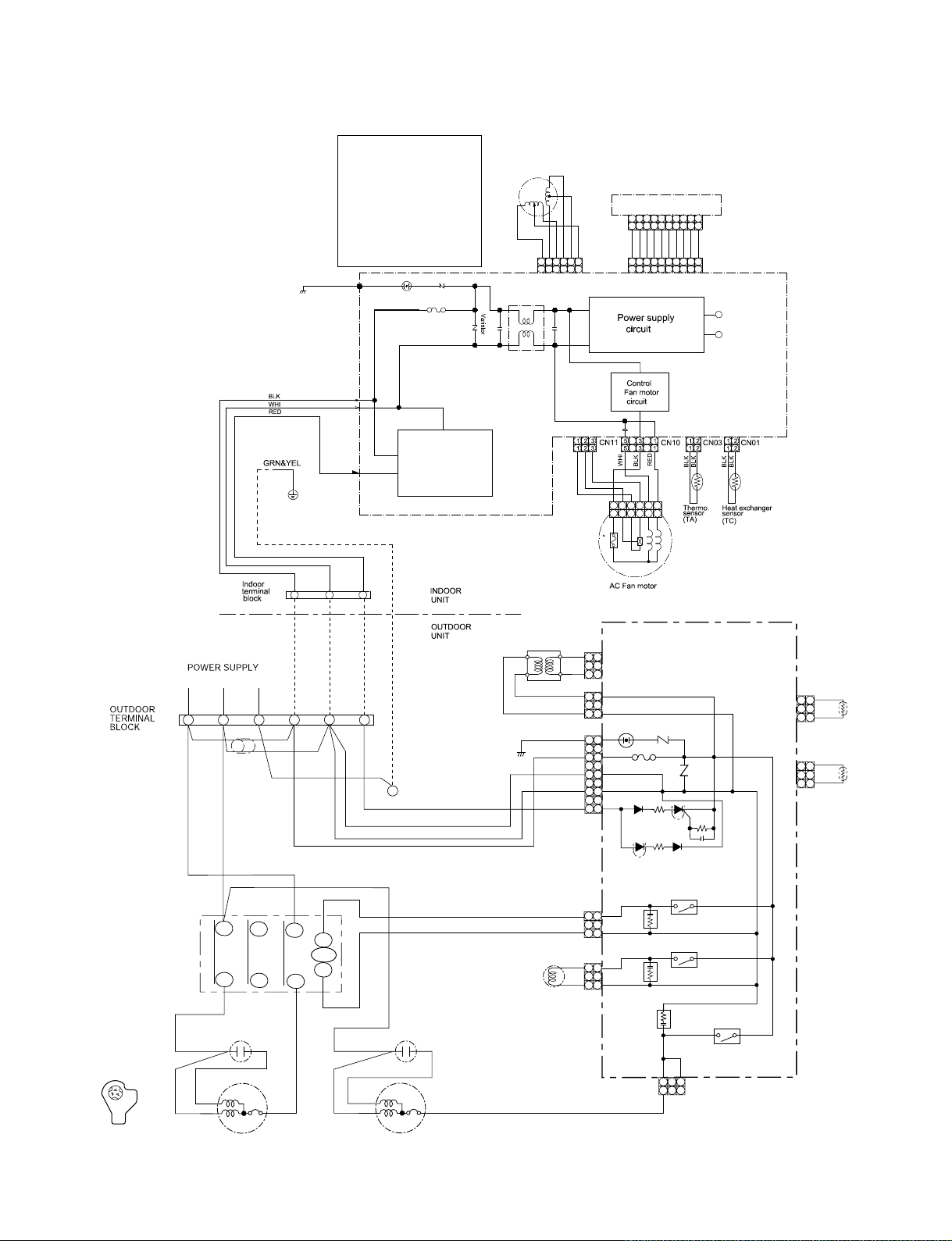
3-2 42CJR018-723 / 38CJR018-723
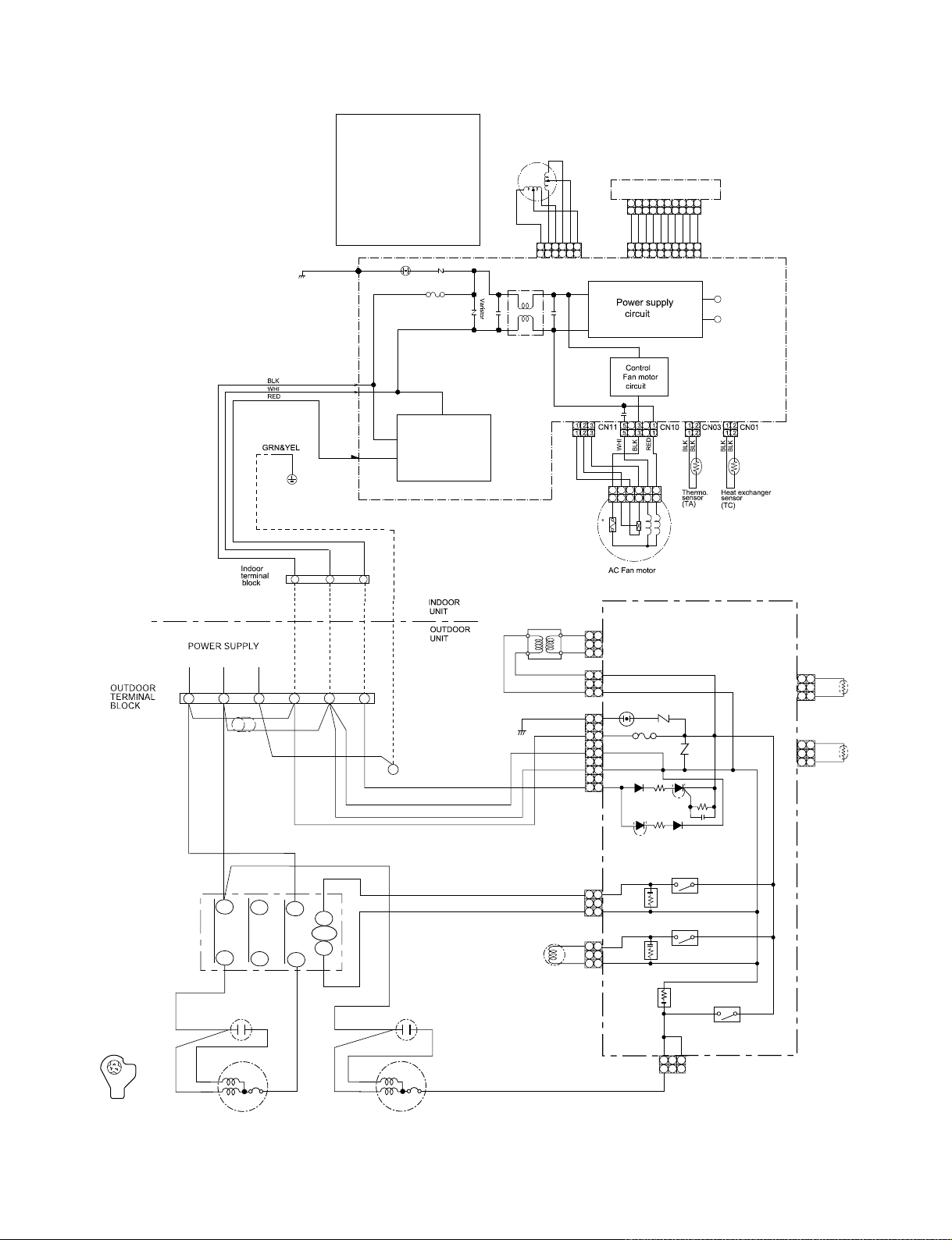
3-3 42TAR018-723 / 38TAR018-723
3-4 42HNR018-713 / 38HNR018-713
3-5 42HNR024-713 / 38HNR024-713
4. SPECIFICATION OF ELECTRICAL PARTS
4-1 Indoor Unit (42CJR024-723, 42CJR018-723, 42TAR024X-723, 42TAR018-723)
4-2 Indoor Unit (42HNR024-713, 42HNR018-713)
4-3 Outdoor Unit (38CJR024-723, 38TAR024X-723)
4-4 Outdoor Unit (38CJR018-723)
4-5 Outdoor Unit (38TAR018-723)
4-6 Outdoor Unit (38HNR024-713)
Outdoor Unit (38HNR018-713)
4-7
5. REFRIGERATION CYCLE DIAGRAM
5-1 42CJR024-723 / 38CJR024-723, 42TAR024X-723 / 38TAR024X-723
5-2 42HNR024-713 / 38HNR024-713
5-3 42CJR018-723 / 38CJR018-723
5-4 42TAR018-723 / 38TAR018-723
5-5 42HNR018-713 / 38HNR018-713
6. CONTROL BLOCK DIAGRAM
6.1 42CJR024-723, 42CJR018-723, 42TAR024X-723, 42TAR018-723
6.2 42HNR024-713, 42HNR018-713
7. OPERATION DESCRIPTION
7-1 Outline of Air Conditioner Control
7-2 Description of Operation Circuit
7-3 High-Temperature Limit Control
7-4 Low-Temperature Limit Control
7-5 Defrost Operation
7-6 Auto Restart Function
7-7 Filter Check Lamp
– 1 –

8. INSTALLATION PROCEDURE
8-1 Safety Cautions
8-2 Installation Diagram of Indoor and Outdoor Units
8-3 Installation
8-4 Indoor Unit
8-5 Outdoor Unit
8-6 How to Set Remote Control Selector Switch
8-7 Others
9. TROUBLESHOOTING CHART
9-1 Troubleshooting Procedure
9-2 Basic Check Items
9-3 Primary Judgement
9-4 Self-Diagnosis by Remote Control (Check Code)
9-5 How to Diagnose Faulty Parts
9-6 Troubleshooting for Indoor Unit
9-7 Troubleshooting for Wiring (Interconnect cable and Serial Signal Wire)
9-8 Troubleshooting for P.C. Board
9-9 Troubleshooting for Remote Control
FILE NO. SVM-05010
10. PART REPLACEMENT
10-1 Indoor Unit
10-2 Outdoor Unit (38CJR024-723, 38TAR024X-723, 38TAR018-723)
10-3 Outdoor Unit (38CJR018-723)
10-4 Outdoor Unit (38HNR024-713)
10-5 Outdoor Unit (38HNR018-713)
11. EXPLODED VIEWS AND PARTS LIST
11-1 Indoor Unit (E - Parts Assy)
11-2 Indoor Unit
11-3 Outdoor Unit (38CJR024-723, 38TAR024X-723)
11-4 Outdoor Unit (38TAR018-723)
11-5 Outdoor Unit (38CJR018-723)
11-6 Outdoor Unit (38HNR024-713)
11-7 Outdoor Unit (38HNR018-713)
– 2 –
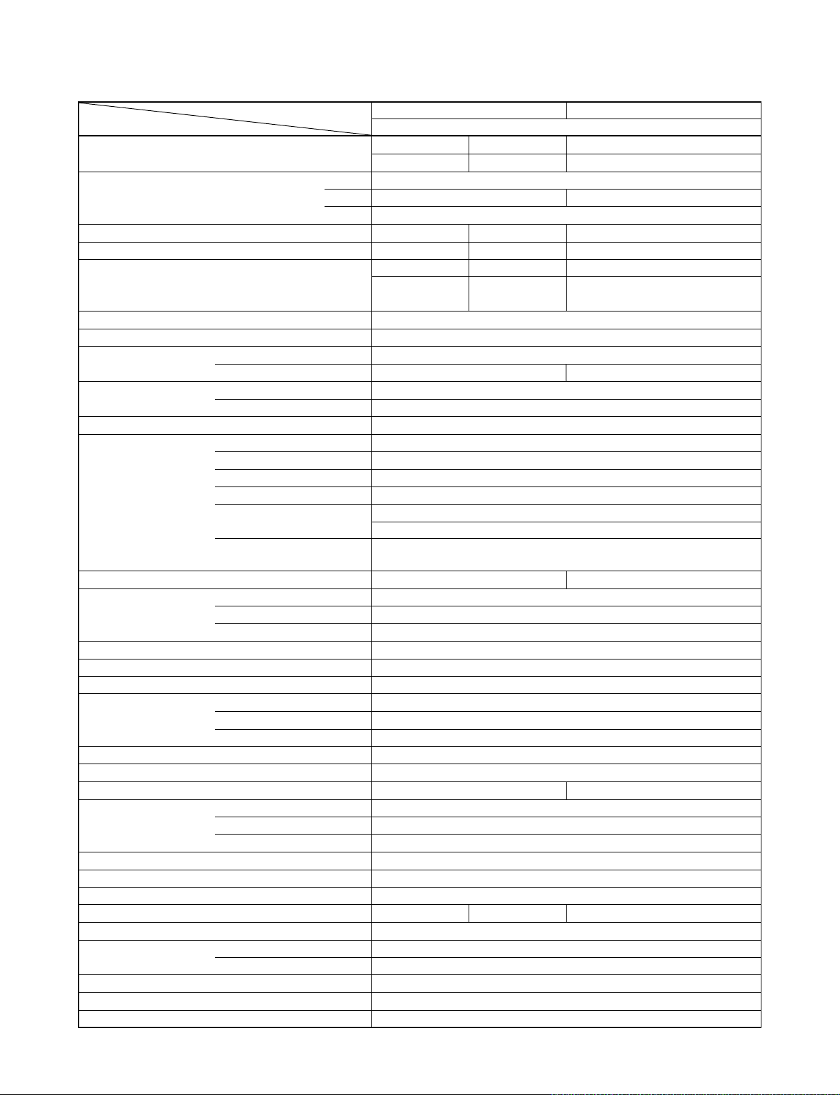
1. SPECIFICATIONS
FILE NO. SVM-05010
ITEM Cooling
Capacity
Power source V 220 – 240 220
Power consumption W 2420 2510 2250
Power factor % 98 92 95
R unning current A
Starting current A 67
Moisture removal lit/h 2.7
Noise
Refrigerant
Refrigerant control Capillary tube
Interconnection Connection type Flare connection
pipe Maximum length
INDOOR UNIT 42CJR024-723 42TAR024X-723
Dimensions Width mm 998
Net weight kg 13
Evaporator type Finned tube
Indoor fan type Cross flow fan
Air volume Medium fan m3/h 750
Fan motor output W 30
Air filter Honeycomb woven filter with PP frame
OUTDOOR UNIT 38CJR024-723 38TAR024X-723
Dimensions Width mm 880
Net weight kg 58
Condenser type Finned tube
Outdoor fan type Propeller fan
Airflow volume m3/h 3380 3560 3380
Fan motor output W 65
Compressor
Safety device IOL
Louver type Automatic louver
Usable outdoor temperature range °C 21 ~ 43
Note
*1 Chargeless pipe
*2 Maximum pipe
Indoor (H/M/L) dB 45/41/37
Outdoor (220 – 240V) dB 56-57 56
Name of refrigerant R22
Rated amount kg 1.70
Gas side size mm ∅15.88
Connection type Flare connection
Liquid side size mm ∅6.35
(One way) 25*
Maximum height
difference
Height mm 298
Depth mm 208
High fan m3/h 900
Low fan m3/h 625
Height mm 690
Depth mm 310
Model PH400X3CS-4KT1
Output W 1800
MODEL
kW
Phase 1∅
Hz 50
Indoor/Outdoor
42CJR024-723 / 38CJR024-723 42TAR024X-723 / 38TAR024X-723
220V 240V 220V
6.40 6.45 6.40
220V 240V 220V
0.3/10.9 0.3/11.1 0.3/10.5
1
m
m10
15*
2
– 3 –
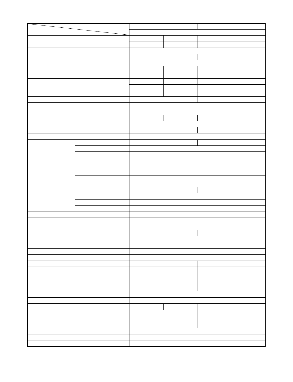
FILE NO. SVM-05010
ITEM Cooling
Capacity
Power source V 220 – 240 220
Power consumption W 1920 2000 1560
Power factor % 92 86 98
Running current A
Starting current A 42 42
Moisture removal lit/h 2
Noise
Refrigerant
Refrigerant control Capillary tube
Interconnection Connection type Flare connection
pipe Maximum length
INDOOR UNIT 42CJR018-723 42TAR018-723
Dimensions Width mm 998
Net weight kg 13
Evaporator type Finned tube
Indoor fan type Cross flow fan
Air volume Medium fan m3/h 667
Fan motor output W 30
Air filter Honeycomb woven filter with PP frame
OUTDOOR UNIT 38CJR018-723 38TAR018-723
Dimensions Width mm 780 880
Net weight kg 41 51
Condenser type Finned tube
Outdoor fan type Propeller fan
Airflow volume m3/h 2120 2200 3380
Fan motor output W 42 65
Compressor
Safety device IOL
Louver type Automatic louver
Usable outdoor temperature range °C 21 ~ 43
Note
*1 Chargeless pipe
*2 Maximum pipe
Indoor (H/M/L) dB 42/39/35
Outdoor (220 – 240V) dB 51 52 56
Name of refrigerant R22
Rated amount kg 1.17 1.47
Gas side size mm ∅12.7 ∅15.88
Connection type Flare connection
Liquid side size mm ∅6.35
(One way) 20*
Maximum height
difference
Height mm 298
Depth mm 208
High fan m3/h 750 900
Low fan m3/h 543
Height mm 550 690
Depth mm 270 310
Model PH340X3C-4KT1 PH290X2C-4FT1
Output W 1500 1700
MODEL
kW
Phase 1∅
Hz 50
Indoor/Outdoor
42CJR018-723 / 38CJR018-723 42TAR018-723 / 38TAR018-723
220V 240V 220V
5.20 5.25 5.10
220V 240V 220V
0.2/9.25 0.2/9.50 0.3/6.94
45/39/33
1
m
m8
15*
2
– 4 –
FILE NO. SVM-05010
MODEL
ITEM
Capacity kW
Phase ∅1
Power source V 220 − 240
Power consumption W
Power factor %
Running current A
Indoor/Outdoor
Starting current A
Moisture removal lit/h
Noise
Refrigerant
Refrigerant control Capillary tube
Interconnection Connection type Flare connection
pipe Maximum length
INDOOR UNIT
Dimensions Width mm 998
Net weight kg 13
Evaporator type Finned tube
Indoor fan type Cross flow fan
Air volume Medium fan m3/h 750
Fan motor output W 30
Air filter Honeycomb woven filter with PP frame
OUTDOOR UNIT
Dimensions Width mm 880 830
Net weight kg
Condenser type Finned tube
Outdoor fan type Propeller fan
Airflow volume m3/h
Fan motor output W
Compressor
Safety device
Louver type Automatic louver
Usable outdoor temperature range °C 21 ~ 43
Note
*1 Chargeless pipe
Indoor (H/M/L) dB 45/41/37 42/39/35
Outdoor (220 − 240 V) dB
Name of refrigerant R22
Rated amount kg 1.75
Gas side size mm ∅15.88 ∅12.7
Connection type Flare connection
Liquid side size mm ∅6.35
(One way) 25*
Maximum height
difference
Height mm 298
Depth mm 220
High fan m3/h 900
Low fan m3/h 625
Height mm 690 538
Depth mm 310 300
Model
Output W
220 V
6.30
Hz 50
2430
96
220 V
0.3/
11.2
m
m
*2 Maximum pipe
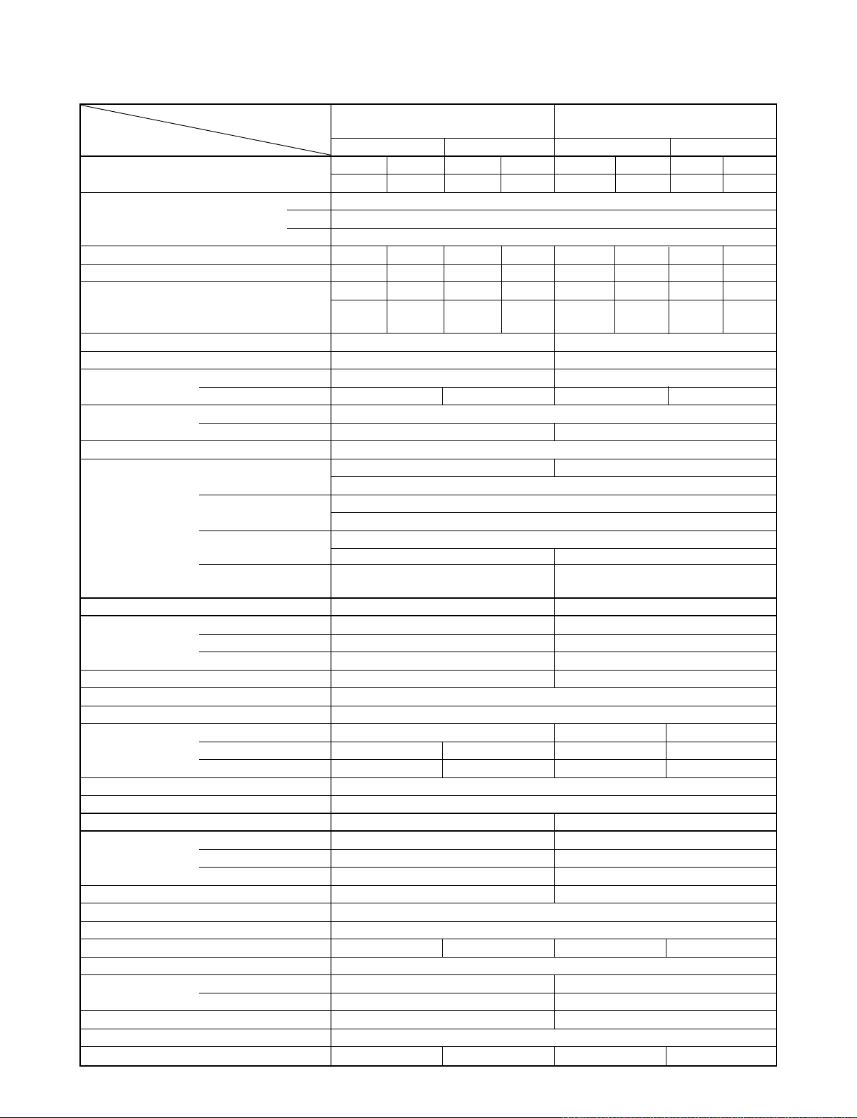
42HNR024-713
38HNR024-713
Cooling
Heating Cooling
240 V
240 V
6.90 5.05
6.30
2510
92
240 V
0.3/
11.1
56-57
42HNR024-713 42HNR018-713
38HNR024-713 38HNR018-713
3380
2JS386D5BB02
IOL, Td Sensor IOL, Td Sensor
220 V
6.80
2390
94
220 V
0.3/
11.2
60
2.5
2
10 8
61 54
1800
−10 ~ 24
2490
90
240 V
0.3/
11.28
57-58
790
667
3560
– 5 –
15*
1
65
220 V
1920
95
220 V
0.2/
9.0
42HNR018-713
38HNR018-713
240 V
5.90
5.05
2040
88
240 V
0.2/
9.5
52-53 53-54
750
667
543
2105 2310
2JS350D5A02
21 ~ 43 −10 ~ 24
45
2.0
1.17
20*
298
998
208
13
1700
220 V
5.80
1800
94
220 V
0.2/
8.5
2
Heating
240 V
1950
86
240 V
0.2/
9.3
800
708
584
Note : 1
• Capacity is based on the following temperature conditions.
FILE NO. SVM-05010
Temperature
Indoor unit inlet air temperature
Outdoor unit inlet air temperature
Note : 2
Charge refrigerant according to the table below.
Refrigerant
*1 No need to charge
extra refrigerant
*2 Need to charge
extra refrigerant
42CJR024-723 / 38CJR024-723 42CJR018-723 / 38CJR018-723
42TAR024X-723 / 38TAR24X-723
42HNR024-713 / 38HNR024-713
Over 15 m up to 25 m (30 g/m)
Condition
Cooling Heating
(DB) 27°C20°C
(WB) 19°C12°C
(DB) 35°C7°C
(WB) 24°C6°C
15 m or less 15 m or less
JIS B8615-1
42TAR018-723 / 38TAR18-723
42HNR018-713 / 38HNR018-713
Over 15 m up to 20 m (20 g/m)
– 6 –
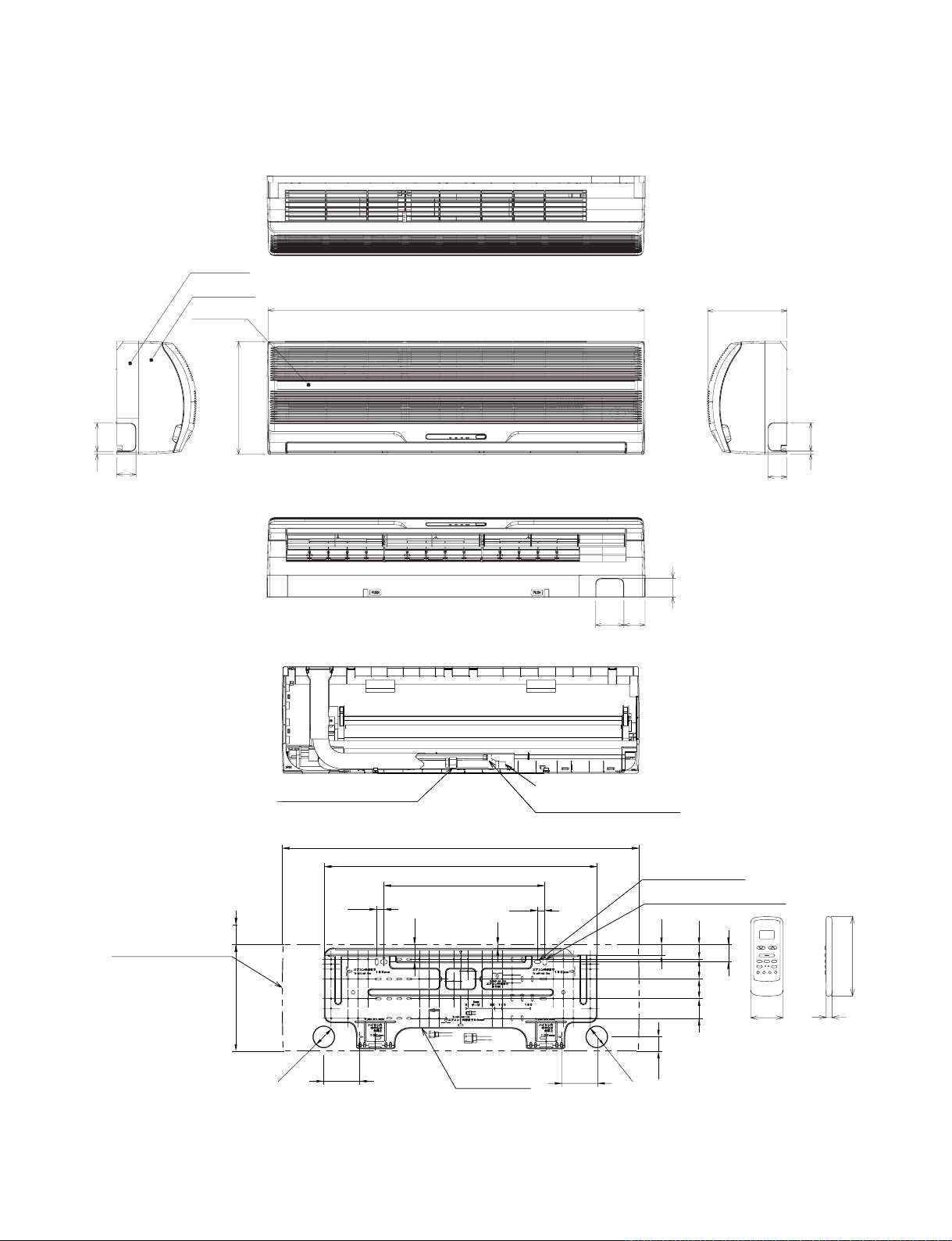
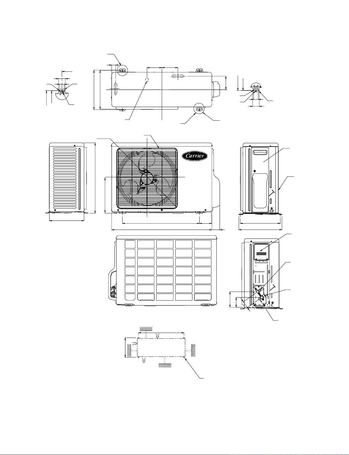
2. CONSTRUCTION VIEWS
2-1. Indoor Unit (42CJR024-723, 42TAR024X-723, 42TAR018-723)
Back body
Front panel
Grille inlet
298
998
FILE NO. SVM-05010
208
775
51
Knock out system Knock out system
50
75 65
Drain hose (0.54 m)
Connecting pipe (0.49 m)
(Flare ∅6.35)
20
10
(For stud bolt ∅6)
(For stud bolt ∅8 − ∅10)
29
41
55
5555
Outline of indoor unit
Connecting pipe (0.39 m)
(Flare ∅15.88)
55 or more
Minimum distance
to ceiling
298
998
763.5
450
20
48
50
48
54
Wireless remote control
850
135
16
∅65
100
Installation
Plate outline
– 7 –
100
∅65
40
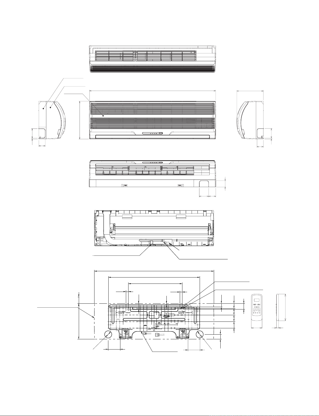
2-2.Outdoor Unit (42CJR018-723, 42HNR018-713, 42HNR024-713)
Back body
Front panel
Grille inlet
298
998
FILE NO. SVM-05010
208
775
51
Knock out system Knock out system
50
75 65
Drain hose (0.54 m)
Connecting pipe (0.49 m)
(Flare ∅6.35)
20
10
(For stud bolt ∅6)
(For stud bolt ∅8 − ∅10)
29
41
55
5555
Outline of indoor unit
Connecting pipe (0.39 m)
(Flare ∅12.7)
55 or more
Minimum distance
to ceiling
298
998
763.5
450
20
48
50
48
54
Wireless remote control
850
135
16
∅65
100
Installation
Plate outline
– 8 –
100
∅65
40
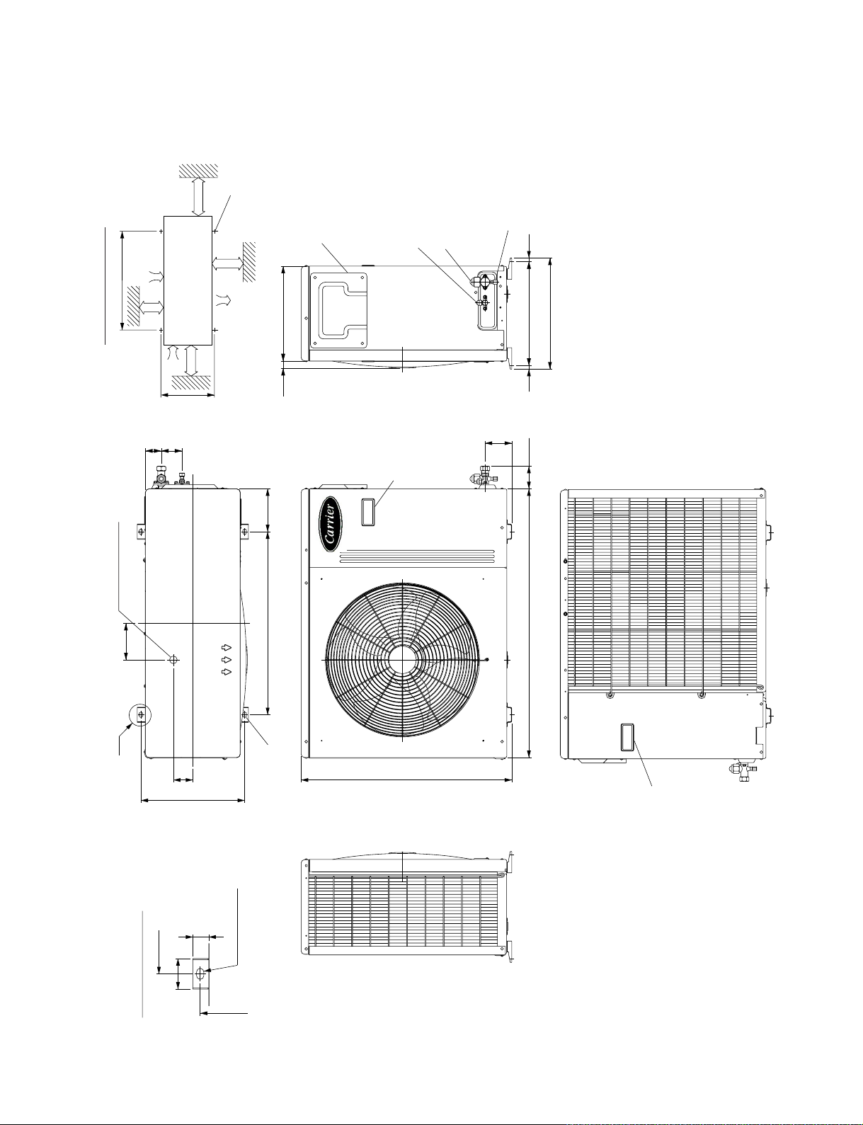
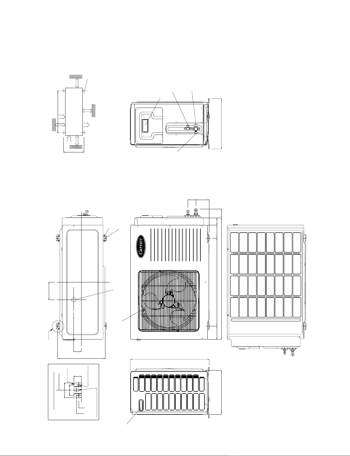
FILE NO. SVM-05010
2-3.Outdoor Unit (38CJR024-723, 38TAR024X-723, 38TAR018-723,38HNR024-713)
for ∅8 − ∅10
anchor bolt
4-∅12x18
600 or
more
600
more
52
Air inlet
340
68
Installation dimension
100 or
∅25 Drain outlet
120
600 or
more
Air outlet
100 or
more
140
600
310
23
Electric
Parts cover
Liquid side
Handle
(Flare ∅6.35)
Gas side
(Flare ∅15.88)
Service Port
12
364
340 (pitch)
12
88
74
880
A
600
A Detail Drawing
50
63.8
340
27
4-∅12x18 holes
∅12x18 hole
340
690
(for ∅8 − ∅10 anchor bolt)
Handle
– 9 –
2-4. Outdoor Unit (38CJR018-723)
A
FILE NO. SVM-05010
A Detail Drawing (Back Leg)
600
52
310
36
302
270
∅6 Hole
R15
R5.5
32.5
310
302
∅30 Drain outlet
∅436
530
265
FAN GUARD
115 125
2-∅11x14 Hole
(For ∅8-∅10 anchor bolt)
600 90
780 62
102
∅6 Hole
∅11x14 Hole
B
B Detail Drawing (Front Leg)
310
302
36
52
R15
310
330
COVER PV
Z
Electrical
part cover
Installation dimension
100 or more
325
100 or more
Z View
Air outlet
600
Air inlet
600 or more
600 or more
120
5
75
4
Service port
4x∅11 Long holes (For ∅8-∅10 anchor bolt)
Liquid side
(Flare ∅6.35)
Gas side
(Flare ∅12.7)
13 Series
−
10
−
2-5. Outdoor Unit (38HNR018-713)
FILE NO. SVM-05010
4x∅11x14
600 or more
600
600 or
Air inlet
Installation dimension
Air inlet
100 or more
more
325
100 or more
anchor bolt
for ∅8 − ∅10
Air
outlet
(for fixing outdoor unit)
8-∅6 holes
6-∅11x14 holes
(for ∅8 − ∅10 anchor bolt)
Liquid side
Electric
Parts cover
6.35)
∅
(Flare
Service Port
12.7)
∅
Gas side
(Flare
344
91 54
60
50
90
120
A
R10
600
50
35
A Detail Drawing
52
325
23
6 hole
∅
11x14 hole
∅
25 Drain outlet
∅
Fan guard
Handle
600
830
90
538
300
– 11 –

FILE NO. SVM-05010-1
3. WIRING DIA GRAM
3-1.42CJR024-723 / 38CJR024-723, 42TAR024X-723 / 38TAR024X-723
COLOR IDENTIFICATION
BRW : BROWN
RED : RED
BLK
CN27
GRN&YEL
WHI : WHITE
YEL : YELLOW
BLU : BLUE
BLK : BLACK
GRY : GRAY
PNK : PINK
ORN : ORANGE
GRN : GREEN
GRN&YEL : GREEN & YELLOW
P04
6.3A
CN30
CN31
Varistor
DSA
F01
250V
MAIN P.C. BOARD
(WP-003)
Varistor
Louver
motor
BLU
PNK
6
5 223311
6
5
Infrared rays receive
and Indication parts
5 98
1 2 3 4 6 10
BLU
BLU
BLU
BLU
YEL
RED
BRW
ORN
4
CN07
4
BLU
1 2 3 4 65 10
5 64
321
Power supply
circuit
Control
Fan motor
circuit
GRY
BRW
YEL
105 64321
8 9
7
7
BLU
BLU
7
7
8 9
CN25
BLU
BLU
WHI
98
CN13
10
2
1
21
1
BLK2BLK
CN03
CN01
2
1
BLK
BLK
OUTDOOR
TERMINAL
BLOCK
POWER SUPPLY
240 V ~ 50 Hz
220 −
(For 38CJR024-723)
220 V ~ 50 Hz
(FOR 38TAR024X-723)
L
N
BLK
RED
BLK
RED
BLK BLK
RED
Indoor
terminal
block
i
SPARK KILLER
A2 A1
52C
1/L1
2/T1
3/L2 4/T2
5/L3 6/T3
1
1
2
2
GRN&YEL
RED
CAPACITOR
3
3
GRY
i
CHASSIS
RED
WHI
PNK
COMPRESSOR
INDOOR
UNIT
OUTDOOR
UNIT
CAPACITOR
S
R
WHI
RED
BLK
C
COMPRESSOR TERMINAL
FAN MOTOR
C
RS
BLK
1
2
4
3
1
2
66554
3
145 C
TEMP FUSE
Thermo.
sensor
(TA)
Heat exchanger
sensor
(TC)
MAGNETIC CONTACTOR
− 12 −
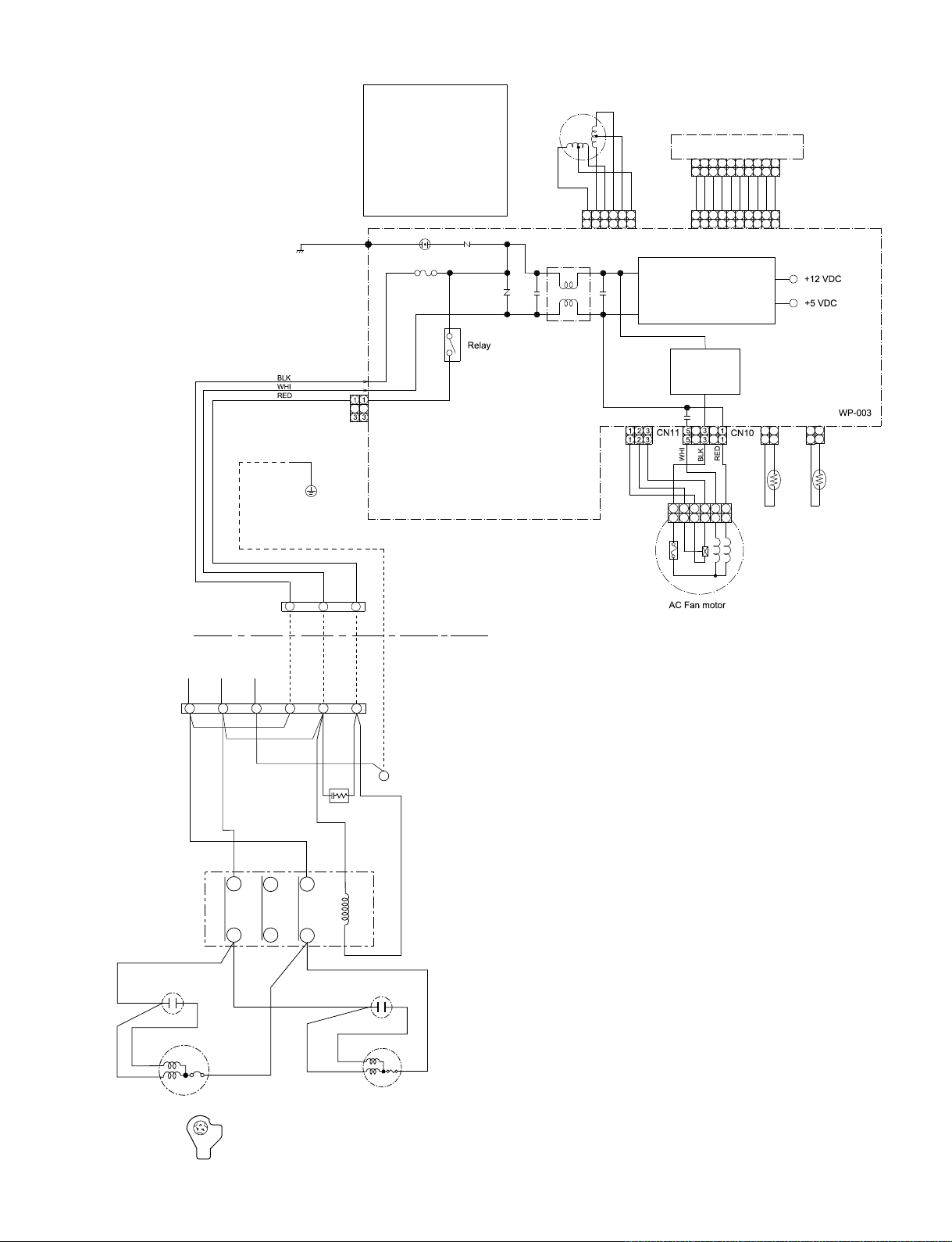
3-2. 42CJR018-723 / 38CJR018-723
COLOR IDENTIFICATION
BRW : BROWN
RED : RED
WHI : WHITE
YEL : YELLOW
BLU : BLUE
BLK : BLACK
GRY : GRAY
PNK : PINK
ORN : ORANGE
GRN : GREEN
GRN&YEL : GREEN & YELLOW
P04
BLK
6.3A
CN30
CN31
CN27
GRN&YEL
Varistor
DSA
F01
250V
MAIN P.C. BOARD
(WP-003)
Varistor
Louver
motor
BLU
PNK
6
5 223311
6
5
FILE NO. SVM-05010-1
Infrared rays receive
and Indication parts
1 2 3 4 6 10
BLU
BLU
BLU
YEL
RED
BRW
ORN
4
CN07
4
BLU
1 2 3 4 65 10
321
Power supply
circuit
Control
Fan motor
circuit
GRY
BRW
YEL
1
2
4
3
1
2
3
5 98
BLU
5 64
66554
BLU
8 9
7
7
BLU
BLU
7
8 9
7
Thermo.
sensor
(TA)
BLU
98
1
105 64321
10
21
BLK2BLK
WHI
CN03
CN25
CN13
2
1
CN01
2
1
BLK
BLK
Heat exchanger
sensor
(TC)
OUTDOOR
TERMINAL
BLOCK
RED
POWER SUPPLY
220 − 240 V ~ 50 Hz
BLK
MAGNETIC
CONTACTOR
CAPACITOR
145 C
TEMP FUSE
Indoor
l
termina
block
L
N
BLK
RED
RED
i
GRN&YEL
1
1
RED
3
2
2
3
i
CHASSIS
GRN&YEL
BLK
BLK
INDOOR
UNIT
OUTDOOR
UNIT
SPARK KILLER
GRY
R
U
T
S
W
V
(or A)
A1
(or B)
A2
CAPACITOR
RED
S
WHI
PNK
C
BLK
R
COMPRESSOR
C
S
R
COMPRESSOR TERMINAL
WHI
RED
FAN MOTOR
BLK
– 13
–
3-3.42TAR018-723 / 38TAR018-723
COLOR IDENTIFICATION
BRW : BROWN
RED : RED
WHI : WHITE
YEL : YELLOW
BLU : BLUE
BLK : BLACK
GRY : GRAY
PNK : PINK
ORN : ORANGE
GRN : GREEN
GRN&YEL : GREEN & YELLOW
P04
BLK
DSA
F01
250V
6.3A
CN30
CN31
CN27
GRN&YEL
Louver
motor
Varistor
Varistor
MAIN P.C. BOARD
(WP-003)
BLU
PNK
6
5 223311
4
6
5
4
FILE NO. SVM-05010-1
Infrared rays receive
and Indication parts
1 2 3 4 6 10
BLU
BLU
BLU
YEL
RED
BRW
ORN
CN07
BLU
1 2 3 4 65 10
321
Power supply
circuit
Control
Fan motor
circuit
GRY
BRW
YEL
5 98
BLU
BLU
5 64
105 64321
8 9
7
7
BLU
7
7
BLU
8 9
CN25
BLU
WHI
98
CN13
10
2
1
21
1
BLK2BLK
CN03
CN01
2
1
BLK
BLK
OUTDOOR
TERMINAL
BLOCK
Indoor
termina
block
POWER SUPPLY
220 V ~ 50 Hz
L
N
BLK
RED
BLK
RED
BLK BLK
RED
l
1
1
i
SPARK KILLER
A1 A2
52C
R U
SV
TW
2
2
GRN&YEL
RED
CAPACITOR
3
3
GRY
i
CHASSIS
RED
WHI
PNK
COMPRESSOR
INDOOR
UNIT
OUTDOOR
UNIT
CAPACITOR
S
R
WHI
RED
BLK
C
COMPRESSOR TERMINAL
FAN MOTOR
C
S
R
BLK
1
2
4
3
1
2
66554
3
145 C
TEMP FUSE
Thermo.
sensor
(TA)
Heat exchanger
sensor
(TC)
MAGNETIC CONTACTOR
− 14 −
.
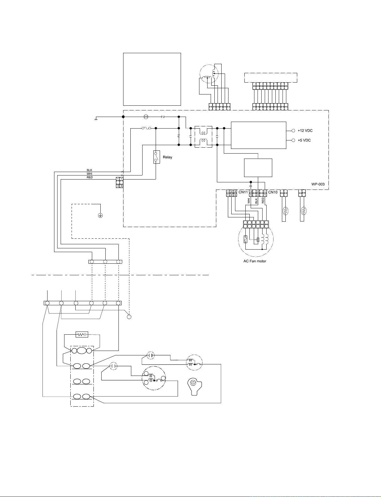
3-4
42HNR018-713 /38HNR018-713
COLOR IDENTIFICATION
BRW : BROWN
RED : RED
WHI : WHITE
YEL : YELLOW
BLU : BLUE
BLK : BLACK
GRY : GRAY
PNK : PINK
ORN : ORANGE
GRN : GREEN
GRN&YEL : GREEN & YELLOW
P04BLK
CN30
CN31
DSA
Varistor
F01
Louver
motor
250V6.3A
MAIN P.C. BOARD
(WP-003)
BLU
PNK
6
5 223311
5
6
FILE NO. SVM-05010-1
Infrared rays receive
and Indication parts
BLU
RED
YEL
ORN
BRW
4
CN07
4
BLU
1 2 3 4 65 10
98 1071 2 3
4 65
4 6
5
BLU
BLU
BLU
BLU
5 64
321
CN25
10
9871 2 3
WHI
BLU
BLU
BLU
98
7
CN13
10
8 9
7
+12 VDC
+5 VDC
WP-003
C
S
R
COMPRESSOR TERMINAL
220 − 240V ~ 50 Hz
L
BLK
RED
BLK
RED
WHI
PNK
N
FERRITE CORE
RED
MAGNETIC
CONTACTOR
R
(1/L1)
(3/L2)
(2/T1)
(4/T2)
U
CAPACITOR
S
R
C OMP R ES S O R
CN23
1
3
2
Serial Signal
circuit
TRANSFORMER
2
1
i
3
GRN&YEL
GRN&YEL
i
CHASSIS
BLK
BLK
RED
RED
BLK
BLK
WHI
RED
GRY
GRY
BRW
YEL
1
2
4
3
1
2
66554
3
145 C
TEMP FUSE
MAIN P.C. BOARD (MCC-890)
1
1
2
3
3
1
1
3
3
1
1
3
3
5
5
7
7
9
9
CN06
CN05
SG01
250VAC T6. 3A
CN01
F01
TNR
R74
TNR
R73
CN07
CN08
DISCHARGE
PIPE
SENSOR (TD)
BLU
1
1
2
3
3
BLU
BLK
1
1
2
3
3
BLK
HEAT
EXCHANGER
SENSOR (TE)
RY07
BLU
1
S
T
A1
(5/L3)
52C
(6/T3)
BLK
A2
W
COIL FOR
4 WAY VALVE
CAPACITOR
RED
WHI
RED
BLK BLK
V
C
YEL
BLU
BLU
313
11
33
CN11
CN02
CR11
CR12
CR13
CN03
1
1
RY05
RY06
3
FA N MO TO R
−15 −
3-5.42HNR024-713 / 38HNR024-713
COLOR IDENTIFICATION
BRW : BROWN
RED : RED
WHI : WHITE
YEL : YELLOW
BLU : BLUE
BLK : BLACK
GRY : GRAY
PNK : PINK
ORN : ORANGE
GRN : GREEN
GRN&YEL : GREEN & YELLOW
P04BLK
CN30
CN31
DSA
Varistor
F01
250V6.3A
MAIN P.C. BOARD
(WP-003)
Louver
motor
BLU
PNK
6
5 223311
5
6
FILE NO. SVM-05010-1
Infrared rays receive
and Indication parts
BLU
RED
YEL
ORN
BRW
4
CN07
4
BLU
1 2 3 4 65 10
98 1071 2 3
4 65
4 6
5
BLU
BLU
BLU
BLU
5 64
321
CN25
10
9871 2 3
WHI
BLU
BLU
BLU
98
7
CN13
10
8 9
7
+12 VDC
+5 VDC
WP-003
C
S
R
COMPRESSOR TERMINAL
220 − 240V ~ 50 Hz
L
BLK
RED
BLK
RED
WHI
PNK
i
N
FERRITE CORE
RED
MAGNETIC
CONTACTOR
R
S
(1/L1)
(3/L2)
(2/T1)
(4/T2)
U
V
CAPACITOR
S
C
R
COMPRESSOR
BLK
1
1
GRN&YEL
T
(5/L3)
(6/T3)
W
A1
52C
A2
2
2
CN23
RED
RED
3
3
WHI
GRN&YEL
i
CHASSIS
CAPACITOR
FAN MOTOR
Serial Signal
circuit
TRANSFORMER
COIL FOR
4 WAY VALVE
BLK
BLK
RED
RED
BLK
BLK
WHI
RED
GRY
BLU
YEL
BLU
BLU
GRY
BRW
YEL
1
1
145 C
TEMP FUSE
1
1
2
CN06
3
3
1
1
CN05
3
3
1
1
3
3
5
5
CN01
7
7
9
9
1
CN11
313
11
CN02
33
BLK BLK
2
4
3
2
66554
3
MAIN P.C. BOARD (MCC-890)
TNR
SG01
R74
F01
250VAC T6. 3A
TNR
R73
RY07
CR11
RY05
CR12
CR13
CN03
3
1
1
RY06
CN07
CN08
DISCHARGE
PIPE
SENSOR (TD)
BLU
1
1
2
3
3
BLU
BLK
1
1
2
3
3
BLK
HEAT
EXCHANGER
SENSOR (TE)
−16 −
FILE NO. SVM-05010
4. SPECIFICATION OF ELECTRICAL PARTS
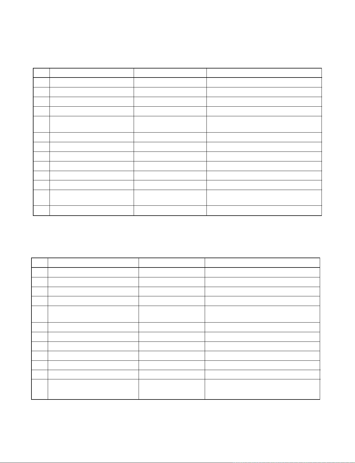
4-1. Indoor Unit (42CJR024-723, 42CJR018-723, 42TAR024X-723, 42TAR018-723)
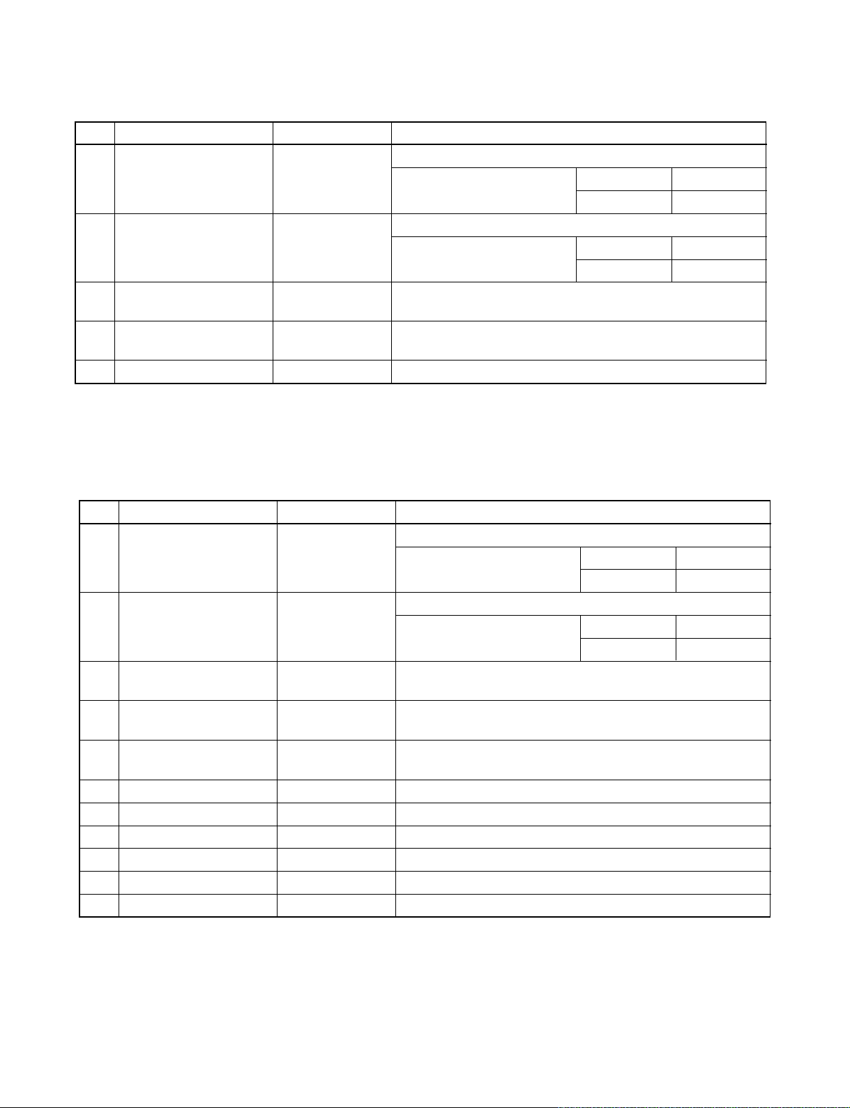
No. Parts name Type Specifications
1 Fan motor (for indoor) AFS-220-31A AC 200 − 240V, 31W
2 Thermo sensor (TA-sensor) ——— 10 kΩ at 25°C
3 Micro Power Module (M01) µRM1260V DC 390 V, Secondary DC 12 V
4 Microcontroller TMP87CM40AN
5 Heat exchanger sensor
(TC-sensor)
6 Line filter (L01) LC*SS11V-06270 27mH, 600mA
7 Diode (DB01) D3SBA60 4 A, 600 V
8 Capacitor (C63) KMH400VSSN47M22S 4.7µF, 400 V
9 Fuse (F01) BET6.3A T6.3 A, 250 V
10 Varistor (R21, R22) 15G561K 560 V
11 Resistor (R319) RF-2TK5R6 5.6Ω, 2 W
12 Louver motor MP35EA12 Output (Rated) 2 W, 10 poles, 1 phase,
13 Relay : (RY04) G5NB-1A Coil DC 12V, 16.7mA, Contact AC 250V, 1A
——— 10 kΩ at 25°C
DC 12 V
4-2. Indoor Unit (42HNR024-713, 42HNR018-713)
No. Parts name Type Specifications
1 Fan motor (for indoor) AFS-220-31A AC 200 V, 31 W
2 Thermo sensor (TA-sensor) ——— 10 kΩ at 25°C
3 Micro Power Model (M01) µ RW1260 V DC 390 V, Secondary DC 12 V
4 Microcontroller TMP87CM40AN
5 Heat exchanger sensor
(TC-sensor)
6 Line filter (L01) LC*SS11V-06270 27 mH, 600mA
7 Diode (DB01) D3SBA60 4 A, 600 V
8 Capacitor (C63) KMN400VSSN47M22S 4.74µF, 400 V
9 Fuse (F01) BET6.3A T6.3A, 250 V
10 Varistor (R21, R22) 15G561K 560 V
11 Resistor (R319) RF-2TK5R6 5.6 Ω, 2 W
12 Louver motor MP35EA12 Output (Rated) 2 W, 10 poles, 1 phase,
——— 10 kΩ at 25°C
DC 12 V
– 17 –
FILE NO. SVM-05010
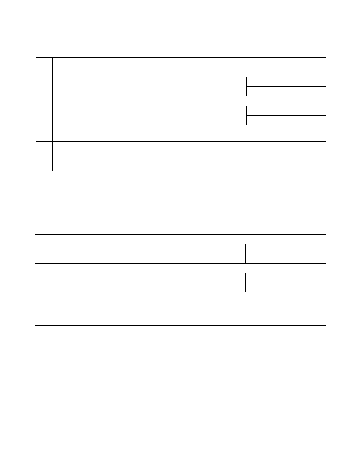
4-3. Outdoor Unit (38CJR024-723, 38TAR024X-723)
No. Parts name Type Specifications
Output (Rated) 2200 W, 2 poles, 1 phase, 220 - 240 V, 50 Hz
1 Compressor PH400X3CS-4KT1 Winding resistance (Ω ) C-R C-S
(at 20°C) 1.13 2.10
Output (Rated) 65 W, 6 poles, 1 phase, 220 - 240 V, 50 Hz
2 Fan motor (for outdoor) KFG6-71SB5P-T Winding resistance (Ω ) Red-Black White-Black
(at 20°C 64.4 127.4
Running capacitor
3
(for fan motor)
Running capacitor
4
(for compressor)
5 Magnetic contactor A35 220 - 240 V, 50 Hz
451355L
BUM44X4505B
AC 450 V, 3.5µ F
AC 440 V, 45
µF
4-4. Outdoor Unit (38CJR018-723)
No. Parts name Type Specifications
Output (Rated) 1500 W, 2 poles, 1 phase, 220 – 240 V, 50 Hz
1 Compressor PH340X3C-4KT1 Winding resistance (Ω) C-R C-S
(at 20°C) 1.46 2.47
Output (Rated) 42 W, 6 poles, 1 phase, 220 – 240 V, 50 Hz
2 Fan motor (for outdoor) WLF-240-42A-1 Winding resistance (Ω) Red-Black White-Black
(at 20°C) 188 289
Running capacitor
3
(for fan motor)
Running capacitor
4
(for compressor)
5 Magnetic contactor CLK-26J 220 – 240 V, 50 Hz
451155L AC 450 V, 1.5µF
BUM44X4505B AC 440 V, 45µF
– 18 –
FILE NO. SVM-05010
4-5. Outdoor Unit (38TAR018-723)
No. Parts name Type Specifications
Output (Rated) 1500 W, 2 poles, 1 phase, 220 – 240 V, 50 Hz
1 Compressor PH290X2C-4FT1 Winding resistance (Ω) C-R C-S
(at 20°C) 1.71 3.09
Output (Rated) 65 W, 6 poles, 1 phase, 220 – 240 V, 50 Hz
2 Fan motor (for outdoor) KFG6-71SB5P-T Winding resistance (Ω) Red-Black White-Black
(at 20°C) 64.4 127.4
Running capacitor
3
(for fan motor)
Running capacitor
4
(for compressor)
5 Magnetic contactor CLK-26J 220 – 240 V, 50 Hz
451355L AC 440 V, 3.5µF
BUM44X3505A AC 440 V, 45µF
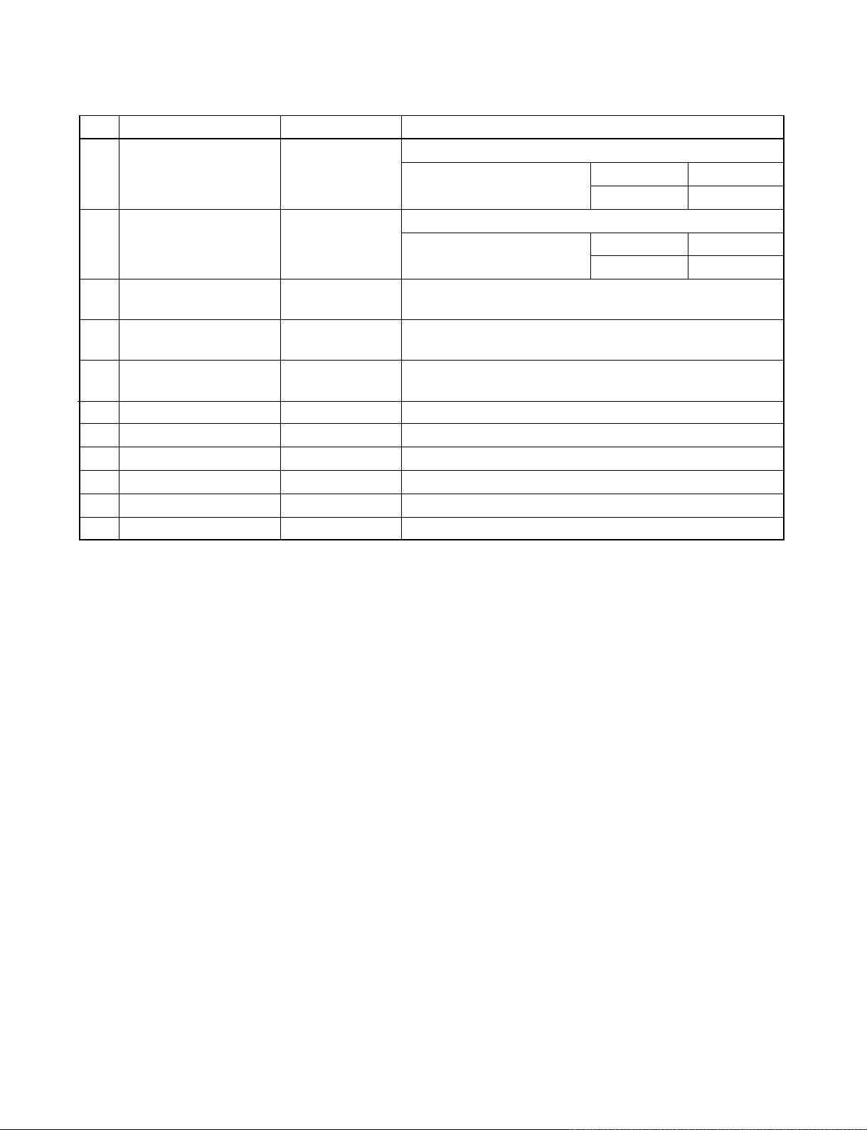
4-6. Outdoor Unit (38HNR024-713)
No. Parts name Type Specifications
Output (Rated) 2200 W, 2 poles, 1 phase, 220 − 240 V, 50 Hz
1 Compressor 2JS386D5BB02 Winding resistance (
(at 20°C) 0.886 1.979
Output (Rated) 65 W, 6 poles, 1 phase, 220 − 240 V, 50 Hz
2 Fan motor (for outdoor) KFG6-71SB5P-T1 Winding resistance (Ω) Red-Black White-Black
(at 20°C) 64.4 127.4
Running capacitor
3
(for fan motor)
Running capacitor
4
(for compressor)
Solenoid coil
5
(for 4-way valve)
6 Thermo sensor TE / TD 10 kΩ at 25°C / 50 kΩ at 25°C
7 Magnetic contactor A35 220 − 240 V, 50 Hz
8 Transformer TT-05 220 − 240 V
9 Microcontroller TMP47C840N
10 Varistor (R73, R74, R86) 15G471K 470 V
11 Fuse (F01) MT3 T6.3 A, 250 V
451355L AC 450 V, 3.5µF
BUM44X6005C AC 440 V, 60µF
VHV (STF) AC 220 − 240 V
) C-R C-S
Ω
– 19 –
FILE NO. SVM-05010
4-7. Outdoor Unit (38HNR018-713)
No. Parts name Type Specifications
Output (Rated) 1500 W, 2 poles, 1 phase, 220 − 240 V, 50 Hz
1 Compressor 2JS350D5DA02 Winding resistance (Ω) C-R C-S
(at 20°C) 0.981 2.845
Output (Rated) 65 W, 6 poles, 1 phase, 220 − 240 V, 50 Hz
2 Fan motor (for outdoor) KFG6-71SB5P-T3 Winding resistance (Ω) Red-Black White-Black
(at 20°C) 64.4 127.4
Running capacitor
3
(for fan motor)
Running capacitor
4
(for compressor)
Solenoid coil
5
(for 4-way valve)
6 Thermo sensor TE / TD 10 kΩ at 25°C / 50 kΩ at 25°C
7 Magnetic contactor CLK-26J 220 − 240 V, 50 Hz, 1P1a
8 Transformer TT-05 220 − 240 V
9 Microcontroller TMP47C840N
10 Varistor (R73, R74, R86) 15G471K 470 V
11 Fuse (F01) MT3 T6.3 A, 250 V
451205L
BUM44X4505B
VHV (STF) AC 220 − 240 V
AC 450 V, 2µF
AC 440 V, 45µF
− 20 −
FILE NO. SVM-05010
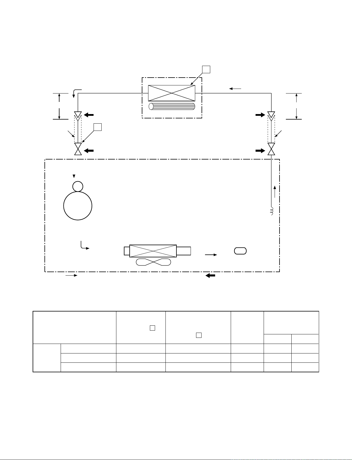
5. REFRIGERATION CYCLE DIAGRAM
5-1. 42CJR024-723 / 38CJR024-723, 42TAR024X-723 / 38TAR024X-723
Indoor unit
Cooling
0.39 m
(Connecting pipe)
∅
15.88
O.D.:15.88 mm O.D.:6.35 mm
Cooling
Compressor
P
Packed valve
(∅15.88)
Gas container connection (Reinstall etc.)
PH400X3CS-4KT1
Evaporator
Cross flow fan
T
0.49 m
(Connecting pipe)
∅
6.35
Packed valve
∅
6.35)
(
Capillary tube
∅2.4 x 1500 s
Cooling
Condenser
Propeller fan
Outdoor unit
Mark ( ) means check points of Gas Leak
Dryer
Refrigerant
R22 1.70 kg
Ambient temp.
50 Hz
Standard
pressure
(MPaG)
P
Surface temp. of heat
exchanger interchanging
pipe
T
(°C)
Fan speed
(indoor)
conditions DB/WB
(°C)
Indoor Outdoor
Standard 0.4 11.0 High 27/19 35/24
Cooling High temperature 0.5 12.0 High 32/23 43/26*
Low temperature 0.3 1.0 Low 21/15 21/15
Note : Measure the heat exchanger temperature at the center of U-bend. (By means of TC sensor.)
– 21 –
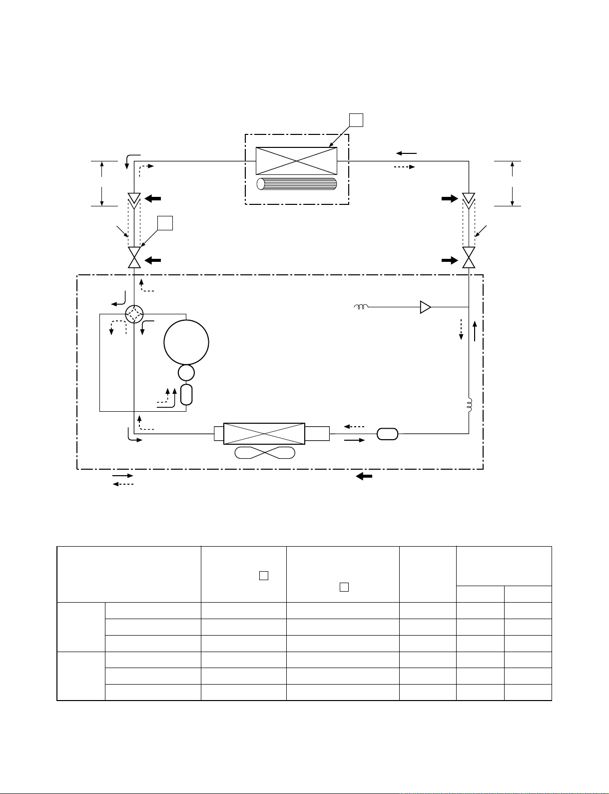
5-2. 42HNR024-713 / 38HNR024-713
FILE NO. SVM-05010
Indoor unit
Cooling
0.39 m
(Connecting pipe)
∅
15.88
O.D.:15.88 mm O.D.:6.35 mm
Cooling
Heating
Heating
P
Packed valve
(∅15.88)
Gas container connection (Reinstall etc.)
Heating
4-way valve
Cooling
Compressor
2JS386D5BB02
Accumulator
Condenser
Evaporator
Cross flow fan
T
Capillary tube
∅
1.0 x 700 s
Dryer
Packed valve
∅
6.35)
(
Capillary tube
∅2.0 x 1000 s
0.49 m
(Connecting pipe)
∅
6.35
Refrigerant
R22 1.
75 kg
Cooling
Heating
Propeller fan
Outdoor unit
Mark ( ) means check points of Gas Leak
Ambient temp.
50 Hz
Standard
pressure
(MPaG)
P
Surface temp. of heat
exchanger interchanging
pipe
T
(°C)
Fan speed
(indoor)
conditions DB/WB
(°C)
Indoor Outdoor
Standard 1.7 43.0 High 20/– 7/6
Heating High temperature 2.3 ~ 2.4 52.0 ~ 59.0 Low 27/– 24/18
Low temperature*1 1.2 36.0 High 20/– –10/–10
Standard 0.4 11.0 High 27/19 35/24
Cooling High temperature 0.6 12.0 High 32/23 43/26
Low temperature 0.3 1.0 Low 21/15 21/15
Note : Measure the heat exchanger temperature at the center of U-bend. (By means of TC sensor.)
*1 : During heating overload, the high temperature limit control operation is included.
– 22 –

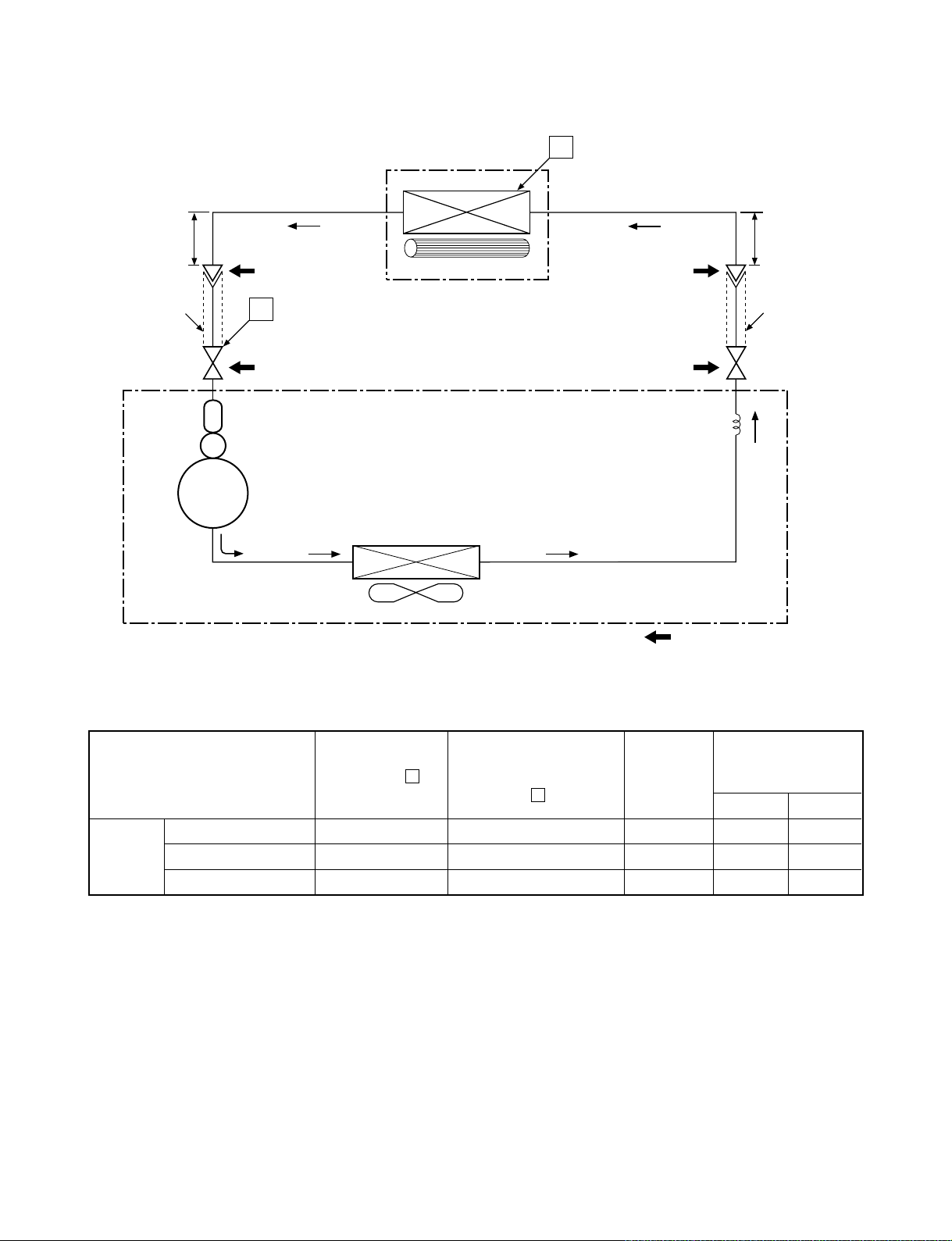
5-3. 42CJR018-723 / 38CJR018-723
FILE NO. SVM-05010
Indoor unit
Evaporator
(Connecting pipe)
0.39 m
∅12.7
O.D.:12.7 mm O.D.:6.35 mm
Compressor
P
Packed valve
(∅12.7)
Accumulator
PH340X3C-4KT1
Cross flow fan
Condenser
Propeller fan
T
0.49 m
(Connecting pipe)
∅6.35
Packed valve
(∅6.35)
Capillary tube
∅2.0 x 1400 s
Refrigerant
R22 1.17 kg
Outdoor unit
Mark ( ) means check points of Gas Leak
Ambient temp.
Surface temp. of heat
exchanger interchanging
pipe
T
(°C)
Fan speed
(indoor)
conditions DB/WB
(°C)
Indoor Outdoor
50 Hz
Standard
pressure
(MPaG)
P
Standard 0.4 11.0 High 27/19 35/24
Cooling High temperature 0.5 13.0 High 32/23 43/26
Low temperature 0.3 2.0 Low 21/15 21/15
Note : Measure the heat exchanger temperature at the center of U-bend. (By means of TC sensor.)
– 23 –
5-4. 42TAR018-723 / 38TAR018-723
FILE NO. SVM-05010
Indoor unit
Evaporator
(Connecting pipe)
0.39 m
∅15.88
O.D.:15.88 mm O.D.:6.35 mm
Compressor
P
Packed valve
(∅15.88)
Accumulator
PH290X2C-4FT1
Cross flow fan
Condenser
Propeller fan
T
0.49 m
(Connecting pipe)
∅6.35
Packed valve
(∅6.35)
Capillary tube
∅2.0 x 800 s
Refrigerant
R22 1.47 kg
Outdoor unit
Mark ( ) means check points of Gas Leak
Ambient temp.
Surface temp. of heat
exchanger interchanging
pipe
T
(°C)
Fan speed
(indoor)
conditions DB/WB
(°C)
Indoor Outdoor
50 Hz
Standard
pressure
(MPaG)
P
Standard 0.5 10.0 High 27/19 35/24
Cooling High temperature 0.6 12.0 High 32/23 43/26
Low temperature 0.3 2.0 Low 21/15 21/15
Note : Measure the heat exchanger temperature at the center of U-bend. (By means of TC sensor.)
– 24 –
 Loading...