


42CA
Carrier 42CA, 42D, 42CE, 42CG, 42CK Product Data
...
42SH STACK
Product
Data
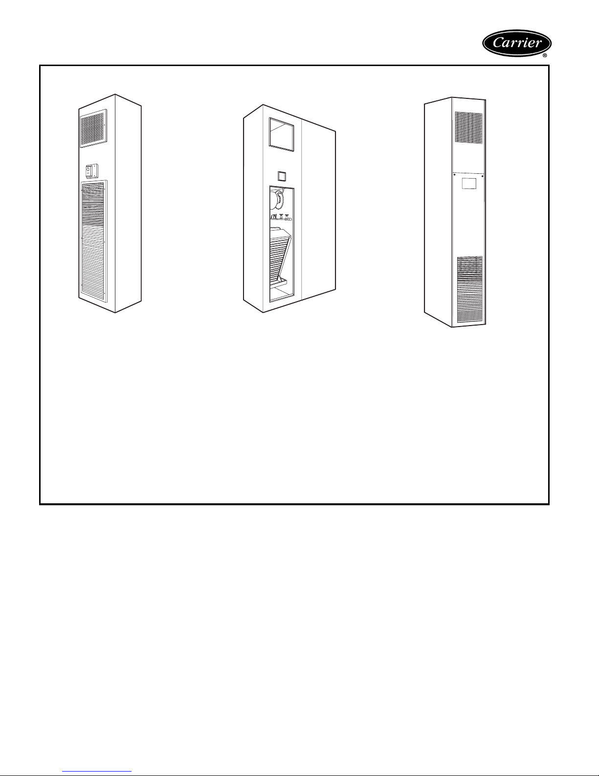
42CA HORIZONTAL
42DA DUCTED
42VB VERTICAL
42C,D,S,V Series
Fan Coil
Air Conditioners
50/60 Hz
150 to 2000 cfm
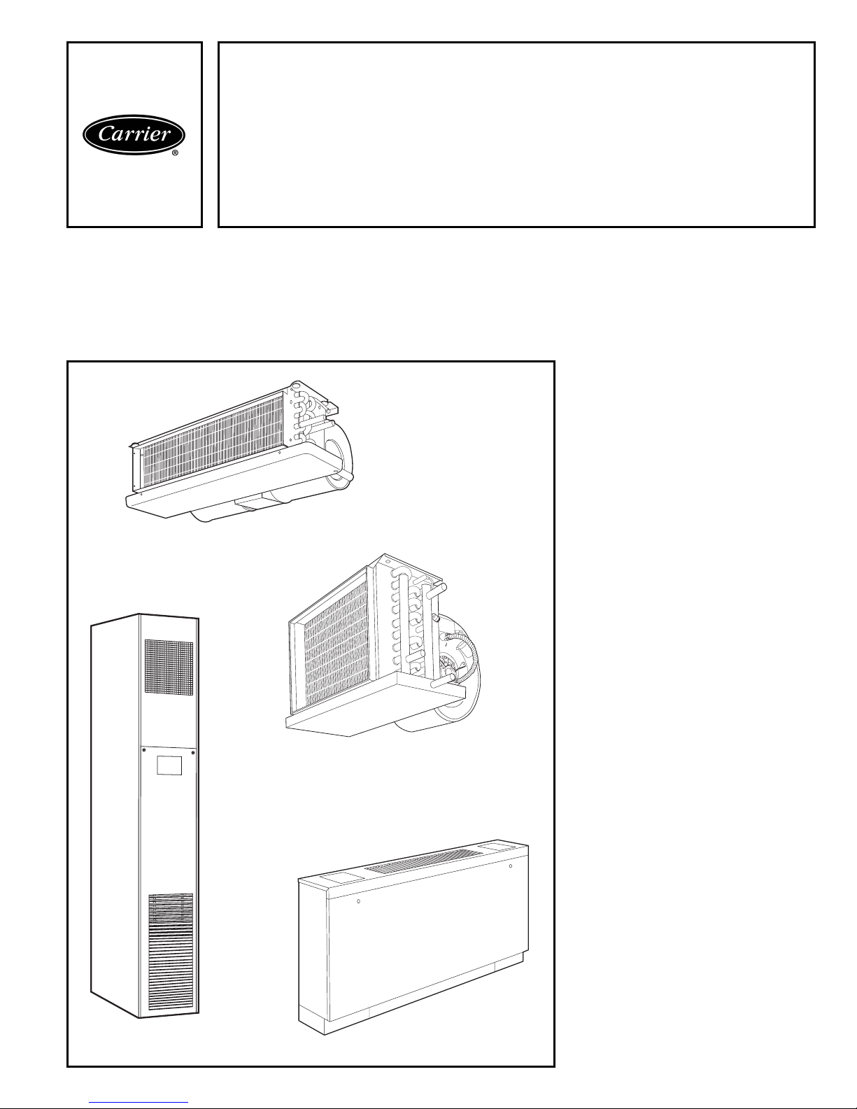
Carrier’s 42C,D,S,V Series fan-coil
units combine design flexibility with
easy, low-cost installation.
Features/Benefits
Versatility
If room fan coils are the answer to your
job requirements, choose from Carrier’s
extensive range of superior fan-coil
units.
With Carrier’s 42 series fan coils, you
can select from 5 horizontal, 6 vertical,
5 ducted or 3 stacked models; furred-in
or cabinet style, slant top or low silhouette, in 150 through 2000 cfm capacities. Coils are available with 1, 2, 3, 4,
or 5 rows (depending on model), to
satisfy a variety of application requirements. The units are ideal for installation in motels, apartments, and other
multi-room buildings. Many optional
control packages are available, including
2-pipe heating and cooling, 2-pipe
heating and cooling with auxiliary electric heat, 2-pipe cooling with total electric heat, and 4-pipe heating and cooling. Also offered are manual and automatic changeover controls and several
thermostat options.
Casings and frame are fabricated from
tough, heavy gage galvanized steel. Optional decorative colors allow the unit to
blend with any interior design.
Low-cost installation and
operation
Each unit is designed to occupy a
minimum space. No complex system
controls are required for Carrier fan coil
units. Piping, drain, and wiring connections are readily accessible and mounting holes and slots are pre-drilled to
save installation time and field labor
expense.
Copyright 2004 Carrier Corporation Form 42-2PD

42 Series quality reduces
service and maintenance
expenses
Condensate drain pan is heavy gage
galvanized steel with closed-cell, fire retardant foam insulation. Units come
standard with Tuf-Skin™ II insulation
for energy savings, sound absorption
and Indoor Air Quality (IAQ) preservation. Water never touches the pan, so
corrosion is minimized and long,
trouble-free life is assured.
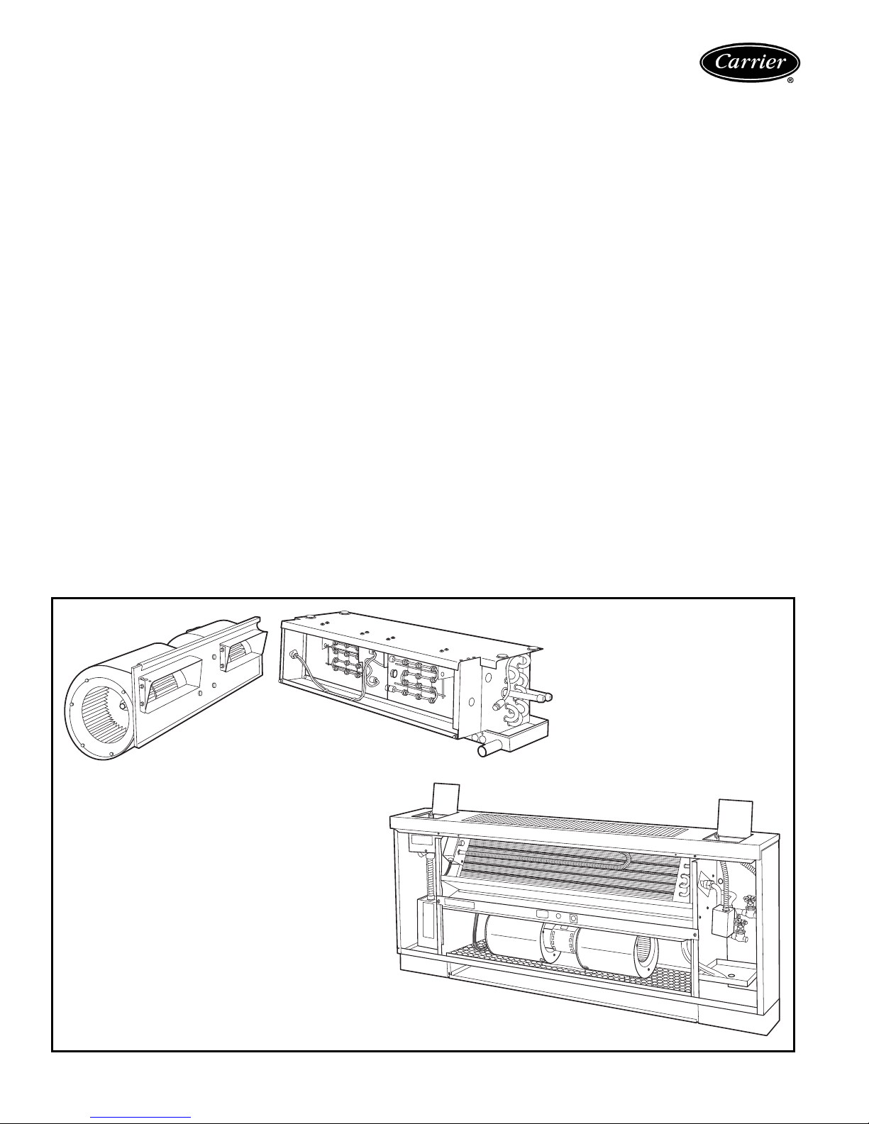
Efficient operation
All units use permanent split capacitor
motors for minimum electrical consumption. Blower wheels are
centrifugal-type, forward curved,
double width, and double inlet sized
for maximum efficiency.
Quiet, dependable
performance
All units are built to operate unobtrusively with quiet motors and fans. In ad-
1
dition,
/2-in. thick sound-absorbing,
multi-density, matt faced, neoprenecoated fiberglass insulation is used to
line the cabinet.
42C series horizontal, 42V
series vertical units
Carrier room fan-coil units operate at
exceptionally low sound levels. A generous amount of insulation absorbs
operating sound and rugged, rigid construction ensures vibration free operation at all fan speeds.
Economical, three-speed fans deliver
just the right amount of conditioned air
for your comfort needs at any load,
and each unit can be shut off when not
in use. Permanent split capacitor motors deliver peak operating efficiency.
By choosing Carrier units, you can
match your application with a wide
range of custom-designed options and
accessories, including electric heat. Filters are cleanable or throwaway type.
Motor bearings are heavy-duty
sleeve type, with oversize oil reservoirs
to assure long bearing life. All coils are
factory leak-tested at 350 psig minimum air pressure.
Carrier room fan-coil units provide
unsurpassed year-round comfort, with
heating and cooling performance
certified in compliance with ARI (Air
Conditioning & Refrigeration Institute)
440-98.
42D ducted units
A drip lip (removable drain pan extension) is provided for field installation on
ceiling models 42DA,DC,DE and DF
when a motorized valve package is ordered. The drip lip is also available as
an accessory for use with other
controls.
Motor/blower assembly can be easily removed from the unit for ease of
service. Removing this assembly provides clear access to the entering air
face of the coil, making coil cleaning a
relatively simple matter. Removable
panels make access to components
and connections easy.
42S stacked units
Each Carrier stack unit comes factoryequipped with insulated supply, return,
and drain risers. The design of the 42S
units allow them to be set one on top
of the other in a vertical column rising
floor to floor up the building. Each
riser has a 3-in. belled section at
the top, so the riser piping can be
connected by only one sweat connection per riser. Field-installed couplings
or internal pipe connections are not
needed.
Each stack unit is factory pre-wired
with all control, motor, and optional
electric heat wiring conveniently terminating in a single, accessible junction
box. Each stack unit requires only one
field power connection.
Field-mounted accessories, such as
the 3-speed switch/thermostat package for furred-in units, are equipped
with a pre-wired quick disconnect plug
for easy installation.
The riser size for the stack units can
be specified to match building requirements so that cutting, sorting, and handling of the risers is not necessary. All
units arrive tagged as specified by the
customer for efficient delivery to the
correct building location.
Units can be loaded onto delivery
trucks so that they can be off-loaded in
the proper installation sequence.
Table of contents
Features/Benefits . . . . . . . . . . . . . . . . . . . . . . . . . . . . . . . . . . . . . . . . . . . . .1-6
Options and Accessories . . . . . . . . . . . . . . . . . . . . . . . . . . . . . . . . . . . . . . . . 7-9
Controls . . . . . . . . . . . . . . . . . . . . . . . . . . . . . . . . . . . . . . . . . . . . . . . . . . 10-12
Application Data . . . . . . . . . . . . . . . . . . . . . . . . . . . . . . . . . . . . . . . . . . . . 13-25
Selection Procedure . . . . . . . . . . . . . . . . . . . . . . . . . . . . . . . . . . . . . . . . . . . . 26
42C,V
Model Number Nomenclature . . . . . . . . . . . . . . . . . . . . . . . . . . . . . . . . . . 27
ARI Capacity Ratings . . . . . . . . . . . . . . . . . . . . . . . . . . . . . . . . . . . . . . . . 28
Sound data . . . . . . . . . . . . . . . . . . . . . . . . . . . . . . . . . . . . . . . . . . . . 29,30
Physical Data and Dimensions . . . . . . . . . . . . . . . . . . . . . . . . . . . . . . . . 31-42
Accessory Dimensions. . . . . . . . . . . . . . . . . . . . . . . . . . . . . . . . . . . . . .43-47
Performance Data . . . . . . . . . . . . . . . . . . . . . . . . . . . . . . . . . . . . . . . 48-63
Electrical Data . . . . . . . . . . . . . . . . . . . . . . . . . . . . . . . . . . . . . . . . . . .64-66
42D
Model Number Nomenclature . . . . . . . . . . . . . . . . . . . . . . . . . . . . . . . . . . 67
ARI Capacity Ratings . . . . . . . . . . . . . . . . . . . . . . . . . . . . . . . . . . . . . . . . 67
Sound data . . . . . . . . . . . . . . . . . . . . . . . . . . . . . . . . . . . . . . . . . . . . . . . 68
Physical Data and Dimensions . . . . . . . . . . . . . . . . . . . . . . . . . . . . . . . . 68-73
Accessory Dimensions . . . . . . . . . . . . . . . . . . . . . . . . . . . . . . . . . . . . . .74-76
Performance Data . . . . . . . . . . . . . . . . . . . . . . . . . . . . . . . . . . . . . . . 77-86
Electrical Data . . . . . . . . . . . . . . . . . . . . . . . . . . . . . . . . . . . . . . . . . . .87-89
42S
Model Number Nomenclature. . . . . . . . . . . . . . . . . . . . . . . . . . . . . . . . . . . 90
ARI Capacity Ratings . . . . . . . . . . . . . . . . . . . . . . . . . . . . . . . . . . . . . . . . 90
Sound data . . . . . . . . . . . . . . . . . . . . . . . . . . . . . . . . . . . . . . . . . . . . . . . 91
Physical Data and Dimensions . . . . . . . . . . . . . . . . . . . . . . . . . . . . . . . . 91-94
Accessory Dimensions. . . . . . . . . . . . . . . . . . . . . . . . . . . . . . . . . . . . . .95-97
Performance Data . . . . . . . . . . . . . . . . . . . . . . . . . . . . . . . . . . . . . . 98-103
Electrical Data . . . . . . . . . . . . . . . . . . . . . . . . . . . . . . . . . . . . . . . . . . . . 104
Guide Specifications — 42C Series . . . . . . . . . . . . . . . . . . . . . . . . . . . . .105,106
Guide Specifications — 42D Series . . . . . . . . . . . . . . . . . . . . . . . . . . . . .107,108
Guide Specifications — 42S Series . . . . . . . . . . . . . . . . . . . . . . . . . . . . . 109-111
Guide Specifications — 42V Series . . . . . . . . . . . . . . . . . . . . . . . . . . . . . 112,113
Page
2
Features/Benefits (cont)
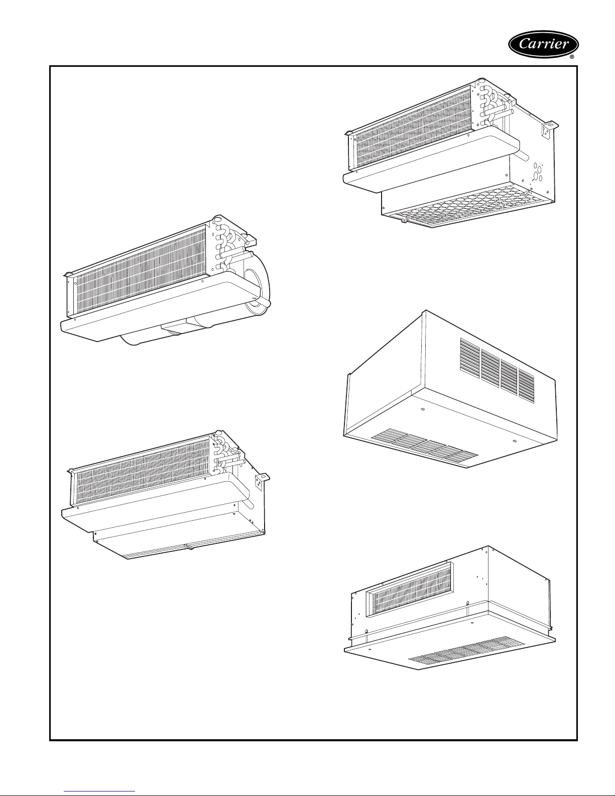
42CF
High-static, furred-in model.
(400-1000 cfm)
42CA
Furred-in ceiling model with low silhouette.
(200-1200 cfm)
42CE
Furred-in ceiling model with factory-installed
plenum.
(200-1200 cfm)
42CG
Cabinet model for under-ceiling mount with
bottom or rear stamped louver return air grille.
(200-1200 cfm)
42CK
Cabinet model with telescoping flip-down panel
and stamped louver bottom return or duct
collar rear return.
(200-1200 cfm)
3
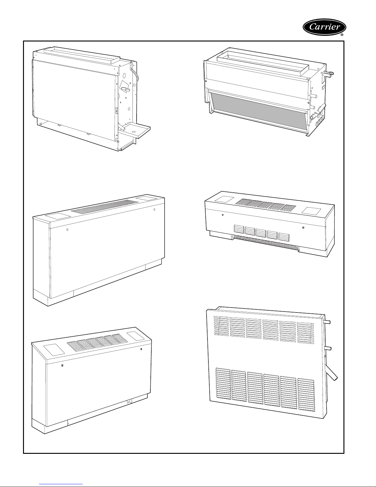
Features/Benefits (cont)
42VA
Furred-in model for under-the-window
applications with top or front discharge.
(200-1200 cfm)
42VC
Furred-in loboy model for concealed under-thewindow applications.
(200-600 cfm)
42VB
Cabinet model with top or
front discharge.
(200-1200 cfm)
42VF
Cabinet model with slant top and
top or front discharge.
(200-1200 cfm)
42VE
Cabinet loboy model with stamped louver discharge grille and 2 control access doors.
(200-600 cfm)
42VG
Furred-in wall model. Available with a 10-in.
valve compartment extension.
(150 and 300 cfm)
4
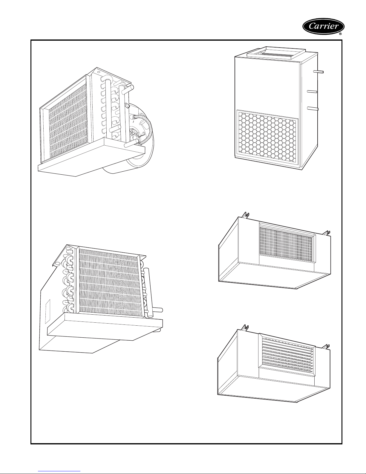
42DA
Furred-in model for installation in the
ceiling or over the closet.
42DD
Vertical model with galvanized casing.
Commonly for closet installation.
42DE
Ceiling model with galvanized casing.
42DC
Furred-in ceiling model with factory-installed
insulated plenum.
42DF
Exposed-ceiling cabinet model with integral double-deflection discharge grille and
a bar-type return-air grille.
5
Features/Benefits (cont)
42SG — Furred-in-stack 42SJ — Back-to-back
furred-in stack
The furred-in-stack is a single unit, constructed of 18-gage galvanized steel
designed for concealed applications in
corners or along room walls. After installation of the unit, only the supply-air
grille, room thermostat, and decorative
return-air grille access panel are visible.
The return-air grille is removable to allow
access for servicing major components.
The grille is furnished in a arctic whitecolored enamel-baked finish. Other colors are available.
The 42SG is also available in master/
slave unit pairs. The pairs are actually 2
separate units shipped individually and
installed and piped together in the field.
The master unit includes risers with
stubout for field piping connections to the
slave unit which has no risers of its own.
The back-to-back furred-in stack is
designed for installation in the separation
wall between 2 separate rooms. The unit
is constructed of 18-gage galvanized
steel. The unit consists of 2 separate
units piped to a set of common risers.
Each unit has its own valves and controls. After installation of the unit, only
the supply-air grille, room thermostat,
and decorative return-air grille panel are
visible.
The return-air grille is removable to allow
access for servicing major components.
The grille is furnished in a arctic whitecolored enamel-baked finish. Other colors are available.
42SH — Cabinet stack
The cabinet stack unit is designed for
applications where concealed installations are not possible or practical. The
unit is constructed of 18-gage galvanized steel with a Arctic White-colored
enamel-baked finish. This model features a double-deflection supply-air grille
and an integral return-air grille access
panel. Controls are normally mounted on
the unit but may also be remote wall
mounted.
6
Options and accessories
Factory-installed options
Coils — Choice of a 2-pipe or 4-pipe system with the fol-
lowing chilled/hot water coil configurations:
• 2-Row Coil (42VC, VE, VG only)
• 3-Row Coil - 42C, D, V, S
• 4-Row Coil - 42D, S
• 4-Row High Capacity - 42V, C, S
• 3-Row High Capacity - 42VC, VE
• 3/1 Opposite End Coil Connections - 42C series,
42VA, 42VB, 42VF
• 3/1 Same End Coil Connections - 42C series, 42VA,
42VB, 42VF, 42S
• 2/1 Same End Coil Connection - 42VC, VE
• 3/2 Opposite End Coil Connections - 42C series,
42VA, 42VB, 42VF, 42S
• 3/2 Same End Coil Connection - 42C series, 42VA,
42VB, 42VF
• 4/1 Opposite End Connections - 42D
• 4/1 Same End Connections - 42D, 42S
• 4/1 High Capacity Opposite End Coil - 42C series,
42VA, 42VB, 42VF
• 4/1 High Capacity Same End Coil - 42C series, 42VA,
42VB, 42VF
• 4/2 Same End Coil Connections - 42D
• 4/2 Opposite End Connections - 42D
• 6-Row High Capacity Coil - 42D
• 6/1 Opposite End Connection - 42DA, DC, DE, DF
• 6/1 Same End Connection - 42DA, DC, DE, DF
• 6/2 Opposite End Connections - 42DA, DC, DE, DF
• 6/2 Same End Connection - 42DA, DC, DE, DF
Decorator colors — A wide variety of colors (Champagne Beige, Toffee Brown, Ermine Grey, and Polar
White) are available to match any interior décor. Select a
desired color from a paint chip chart, Catalog number
842-011, or provide paint chip for matching. Standard
color is now Arctic White; the other colors require a special
quote. Decorative colors may be applied to:
• Cabinet of 42VB, VF, VE, VG
• Cabinet of 42CG
• Panels 42S
• Bottom Panels of 42CK
• Wall Panels of 42VA
• Cabinet 42DF
Electric heaters — Coils are of high grade single-phase,
nichrome resistance wire, insulated by ceramic insulators in
plated steel brackets. Heater sizes available are shown in
the application data section for the respective units. Not
available on 42VG units.
Filters — Each unit (except the 42CA, VG unit) includes a
fiberglass throwaway filter sized for low velocity and maximum efficiency. The standard option will filter both returnand outside-air. Optional permanent aluminum filters with
cleanable, non-aluminum filter media are available for
42CE, CF, CG, CK, DC, DD, DE, all 42V series, and all
42S series units.
Manual air vents — Each standard coil includes a manual air vent to allow venting at the coil if necessary for
quick, complete air elimination.
Outside-air opening/damper — Damper is adjustable
from 0 to 25% and provides ventilation air to unit. (Available on 42VA, VB, VF and 42S series units.)
Single power source connection — Provides factoryinstalled junction box to allow use of single power source
for motor and heater when they are of the same voltage.
For 42D and 42S series units.
Stamped toe space return-air grille — (42VB,VF units.)
Tamperproof “Camloc” fasteners — Camloc fasten-
ers are installed on the access panels and are available for
all cabinet model units.
Thermostat control packages — The standard thermostat control option is line voltage. Unit-Mounted line
voltage and 24V thermostats are available on the 42V
series units. For thermostat control package options refer
to pages 10-12.
Field-installed accessories
Automatic air vents — Automatic air vents have fiber
washers which allow air in the pipes to pass through, automatically bleeding the system, and eliminating the need to
manually remove air from the system. When wet, washers
swell and seal the system.
Decorative wall panels — Wall panels are available for
use with fully recessed 42VA units.
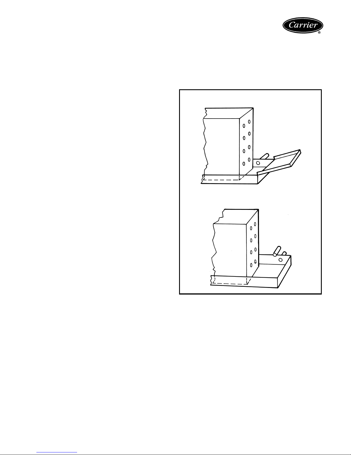
Drip lips (removable drain extension) — Drip lips are
frequently used when valves are added after unit installation and space limitations will not permit use of an
extended drain pan. The drip lip is placed on the end of
the drain pan and is pitched toward the pan to ensure
proper drainage. The drip lip gives positive control of condensate from valves and controls on 42DA, DC units (available as an option on 42DE, DF units). Provided as standard
on these units when factory-supplied motorized valve package is ordered. The drip lip is also installed on the 42C
series ceiling fan coil units when 2-way or 3-way motorized
valve packages are ordered.
Panels, frames, and grilles — Panels, frames, and
grilles on the 42S series units can be chosen in a wide variety of combinations to suit room decorating requirements
and allow access to the unit for maintenance. Discharge
grilles are double deflection type, aluminum finish or
painted. Return-air access panels containing return-air
grilles are available in five different types as illustrated on
page 97.
PANELS, FRAMES AND GRILLES
PANEL
NO.
Standard, 18-gage galvanized steel. Coated with baked-on
1
Arctic White enamel finish. Attached to unit with
fasteners.
18-gage galvanized steel. Coated with baked-on Arctic White
2
enamel finish. Includes access door for concealed unitmounted controls.
Bar-type extruded aluminum with frame matching double
3
deflection supply grille. Fastens to wall and unit with 1
long screws.
4
18-gage galvanized steel. Coated with baked-on Arctic White
and
enamel finish. Frame mounted on sheetrock with screws.
5
Panel mounted in frame with
All Each panel provides access to all internal components.
DESCRIPTION
1
/4turn fasteners.
1
/4turn
1
/2in.
7
Options and accessories (cont)
Return-air grilles — Stamped-type return-air grilles are
standard on 42C, V, S units. Anodized aluminum hinged
bar-type grilles are installed on 42CG, CK and DF (available as an option on 42DA, DC, DE, DD) units.
Risers — The 42S series units can accommodate ¾-in.
(supply and return) and 1-in. (drain) to 2½-in. riser sizes in
2-pipe systems. For other applications, such as reverse
return risers or 4-pipe systems, it may be necessary to
accommodate the additional risers.
Condensate drains are available in sizes down to 1-in. for
greater cost economy. Riser size-reducers are factoryinstalled and for risers of over 115-in. length, filler pieces
can be furnished for field installation.
Riser expansion — When necessary, the 42S series
units are provided with factory-installed expansion loops.
These expansion loops provide up to 1 ½-in. of riser
expansion within the standard unit construction. This
means that the unit can be used on installations of up to 20
floors without any additional expansion devices.
Risers material and insulation — The 42S series unit
factory-installed supply, return, and drain risers can be furnished in type M or L copper. All factory-furnished risers
are insulated with flexible closed foam insulation in ½-in. or
¾-in. thickness.
Supply-air grilles — Two types of double deflection
supply-air grilles are available for horizontal and vertical
units; an integral steel grille painted to match the unit or a
separate unpainted anodized aluminum grille. Not applicable to 42VG units.
Tell-tale drain pan — A secondary drain connection is
located above the primary drain to act as a “tell-tale” in the
event that the primary drain becomes obstructed. They can
be applied to either the main drain pan or an extended
main drain pan. This option only available on the 42C,
42V (except 42VG), and 42DA, DC, DE, DF.
Thermostats control packages — The standard thermostat control option is line voltage. Wall-mounted line
voltage and 24-v thermostats are available on the 42 series
fan coil units. 24-v thermostat is not available on the
42VC,VE,VG unit. Thermostat control packages options
refer to page 10-12.
Trim strips — Strips are available for use with partially
recessed vertical 42VA units and 42S only.
Wall boxes — Wall boxes are all aluminum with insect
screen behind louvers. The wall boxes are available on all
42V series units except the 42VG units.
DRIP LIP
(Horizontal Unit)
“TELL-TALE” DRAIN PAN
(Horizontal Unit)
8
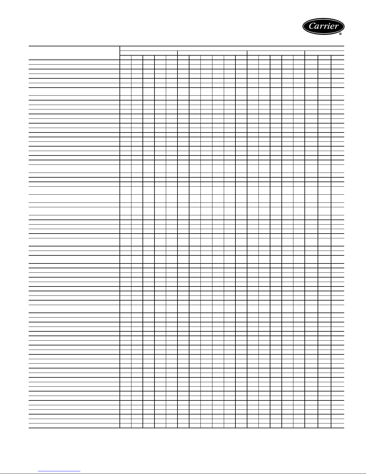
AVAILABLE OPTIONS AND ACCESSORIES
FAC TORY-INSTALLED OPTIONS AND
FIELD-INSTALLED ACCESSORIES
AIR VENT
Automatic Air Vent •••••••••••••••• • • •
Manual Air Vent Std Std Std Std Std Std Std Std Std Std Std Std Std Std Std Std Std Std Std
CABINET CHANGES
Front Panel, 16 Gage ••
Front Panel, 18 Gage Std Std Std Std Std Std Std Std Std Std Std Std Std Std Std Std Std Std Std
Extended Cabinet w hen Electric Heat
or Valves are Installed
Valve Compartment Extension, 10 in. •
Stamped Toe Space Return Gr ille ••
COILS
2-Row (Cooling Only) Std Std Std
3-Row (2-Row Cooling, 1-Row Heating) ••
3-Row (High-Capacity) Std Std Std Std Std Std Std Std • • • • • • • Std S td Std
4-Row (3-Row Cooling, 1-Row Heating) • ••••••• ••••• • • •
4-Row (High-Capacity) • ••••••• StdStdStdStdStd• • •
5-Row (4-Row Cooling, 1-Row Heating) •••••••• ••••• • • •
5-Row (3-Row Cooling, 2-Row Heating) •••••••• •••••
6-Row (4-Row Cooling, 2-Row Heating) •••••
6-Row (High-Capacity) •••••
7-Row (6-Row Cooling, 1-Row Heating) •••••
8-Row (6-Row Cooling, 2-Row Heating) •••••
DAMP ERS
Manual — Adjustable through Return
Air Opening
Manual Adjustment, Remote Mounted ••• • • •
Manual — Rear Opening with ••• • • •
Sliding Damper — No t Filtered •••
Outdoor Air Connection (6 in.), with
Filter and with or without Damper
Damper, Linkage and Motor Wired to
Auxiliary Contact o f 3-Speed Swit ch
DECORATIVE COLORS
(See Carrier Fan Coil Paint Sele ctor
Guide)
DISCHARGE GRILLES
Stamped Front Discharge Std Std Std Std Std
Double Deflection, Installed ••••
Double Deflection, Shipped Loose • • • • Std Std Std Std Std Std Std Std
DRAIN PANS
Sprayed on Closed-Ce ll Foam on Inside
Main Drain Pan
Auxiliary Plastic Drain Pan Std Std Std
Auxiliary Steel Drai n Pan Std Std
AuxiliaryDripLip—Includedwith2-or
3-Way Motorized Valves
Tell-Tale, with Second Drain Connection •••••••••• ••••
Stainless Steel •••••••••••••••• • • •
DUCT COLLAR
Discharge Std Std Std Std Std Std Std Std Std Std Std Std Std Std Std Std
ELECTRIC HEATERS
Nichrome Wire Strip Heater ••••• ••••• • • •
Sheath Type Heater •••••
FAN SW ITC H
Unit-Mounted, Wired and Installed Std Std Std Std S td Std
Wall-Mounted with Plate for
Field-Mounting
FILTERS
Permanent Filter •••• ••••• •• • • • •
Throwaway Filter Std Std Std Std Std Std Std Std Std
LEVELING LEGS • • • • • Std Std Std Std Std Std Std
INSULATION
Foil Faced Insulation •••••••••••••••• • • •
Tuf -S kin II Std Std Std Std Std Std Std Std Std Std Std Std Std Std Std Std Std Std Std
Tuf-Skin RX Insulation •••••••••••••••• • • •
MOTORS
120-1-60, 3-Spee d Std Std Std Std Std Std Std Std Std Std Std Std Std Std Std Std Std Std Std
208-1-60, 3-Spee d •••••••••• ••••• • • •
230-1-60, 3-Spee d •••••••••• ••••• • • •
277-1-60, 3-Spee d •••••••••• ••••• • • •
220-1-50, 3-Spee d •••••••••• ••••• • • •
MOTOR QUICK-DISCONNECT PLUG Std Std Std Std Std Std Std Std Std Std Std Std Std Std Std Std Std Std
OUTSIDE-AIR WALL BOX •••
RETURN AIR GRILLE, Shipped Loose
Stamped Return Grille Std Std Std Std Std Std Std Std Std Std Std Std Std Std
Hinged Panel Std Std • • • Std •
TAMPERPROOF LOCKS (Camloc)
Access Panels ••• •• • • •
Access Doors ••• ••
VALVE PACK AGE S •••••••••••••••• • • •
WALL PANELS (for Recessed Unit) •
WIRING PACKAG ES •• •••••••••••••• • • •
• — Available as a Factory-Installed Option or a Field-Installed Accessory
Std — Stan dard
AVAILABLE
LEGEND
Ceiling — Horizontal Floor — Vertical Ducted — Horizontal Stack — Vertical
CA CE CG CK CF VA VB VF VC VE VG DA DC DE DF DD SG SH SJ
••• • • •
•••
•••
•• ••• •• • • • •
Std Std Std Std Std Std Std Std Std Std Std Std Std Std Std Std Std Std
••••• StdStd••
Std Std Std Std Std Std Std Std Std Std Std Std Std
UNIT SERIES — 42
••
9
Controls
Use the Control Selection guide to make sure that all
necessary components are provided for and that the components are compatible with the required control system.
NOTE: When thermostatic fan control is selected or when
unit outside air dampers are used, unit-mounted thermostats are not recommended as their use will result in poor
room temperature sensing.
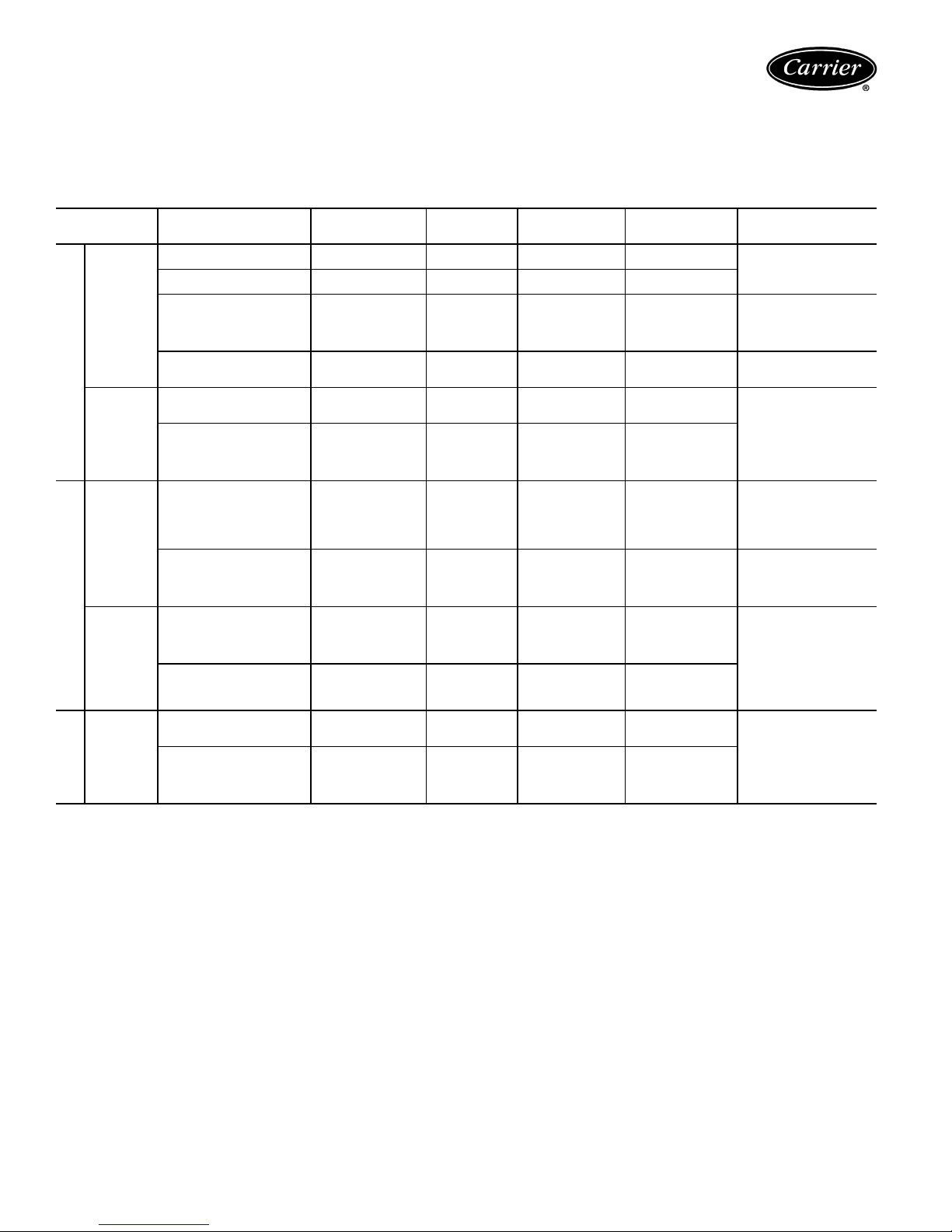
CONTROL SELECTION GUIDE
SYSTEM DESCRIPTION THERMOSTAT
Fan
Control
(2-Pipe)
Twoposition
electric
valves
2-PIPE HEATING-COOLING*
(2-pipe)
Twoposition
electric
valve with
Auxiliary
Electric
Heat
(2-pipe)
Twoposition
electric
ELECTRIC HEAT
valve with
total
electric
heat
(2-pipe)
Twoposition
electric
valves
(4-pipe)
4-PIPE
*If system is HEATING-ONLY or COOLING-ONLY, no changeover or bypass is required.
NOTE: Unit-mounted thermostats are not recommended with either fan-cycle control or applications with outside air dampers.
Fan manually cycled None None None Standard 3-SpeedSWNot recommended
Thermostat cycles fan on-off
from speed set with fan switch.
Thermostat cycles fan on-off
from fan speed set with switch.
Mode automatically switched
by changeover sensing water
temp.
Thermostat cycles fan from
high to low on cooling and low
to off on heating.
Thermostat cycles valve
open or closed.
Thermostat cycles valve
open or closed. Mode automatically switched by
changeover sensing water
temp.
Thermostat cycles valve
open or closed. 2° F after
valve closes, thermostat
activates electric heater.
Heater cannot turn on if hot
water is in coil.
Thermostat cycles valve
open or closed. Manual
changeover switch changes
thermostat to heat to activate
electric heater.
Thermostat cycles valve
open or closed. Manual
changeover switch changes
thermostat to heat to activate
electric heater.
Thermostat cycles valve
open or closed. 2° F after
valve closes, thermostat activateselectricheater.
Thermostat cycles cooling and
heating valves open or closed.
Thermostat cycles cooling
valve open or closed. 2° F
after valve closes, thermostat
cycles heating valve open or
closed.
Wall mounted includes
heat-cool switch.
Wall moun ted.
Heating/cooling
Thermostat
Wall or unit mounted Yes None No Standard 3-Speed
Wall mounted includes
heat-cool switch.
Wall or unit mounted.
Heating/cooling
Thermostat
Wall or unit mounted.
Sequenced heating
and cooling.
Wall moun ted
includes heat-cool
switch.
Wall mounted includes
heat-cool switch.
Wall or unit mounted.
Sequenced heating
and cooling
Wall mounted includes
subbase with heatcool switch.
Wall or unit mounted.
Sequenced heating
and cooling.
CHANGEOVER
ON
SUPPLY PIPE
None None Thermostat has inte-
Yes None Standard
None Motorized (N.C.)
Yes Motorized (N.C.)
Ye s .
Two Required.
None Motorized 3-way or
None Motorized (N.C.)
None Motorized (N.C.)
None Motorized (N.C.)
None Motorized (N.C.)
VALVE
3-way or 2-way,
no bypass required.
3-way or 2-way
Motorized 3-way or
2-way
2-way, no bypass
required
3-way or 2-way,
no bypass required
3-way or 2-way,
no bypass required
3-way or 2-way
(requires 2 valves)
3-way or 2-way
(requires 2 valves)
gral 3-Speed SW
3-Speed SW
Switch, ON-OFF toggle SW only
Thermostat has integral 3-Speed SW
Standard 3-Speed
SW. Others have thermostats with integral
3-Speed SW
Standard 3-Speed
SW. Others have thermostats with integral
3-Speed SW
Thermostat has integral 3-Speed SW
Thermostat has integral 3-Speed SW
Standard 3-Speed
SW
Thermostat has integral 3-Speed SW
Standard 3-Speed
SW. Others have
thermostats with integral 3-Speed SW
FA N
SWITCH (SW)
NOTES
for high humidity
application
Unit-mounted thermostats
provide very poor room
temperature control
Best fan cycle control for
high humidity applications
Valve packages with belled
end(s) for field soldering to
coil.
Valve packages with belled
end(s) for field soldering to
coil.
Valve packages with belled
end(s) for field soldering
to coil.
Valve packages with belled
end(s) for field soldering
to coil.
Valve packages with belled
end(s) for field soldering
to coil.
10
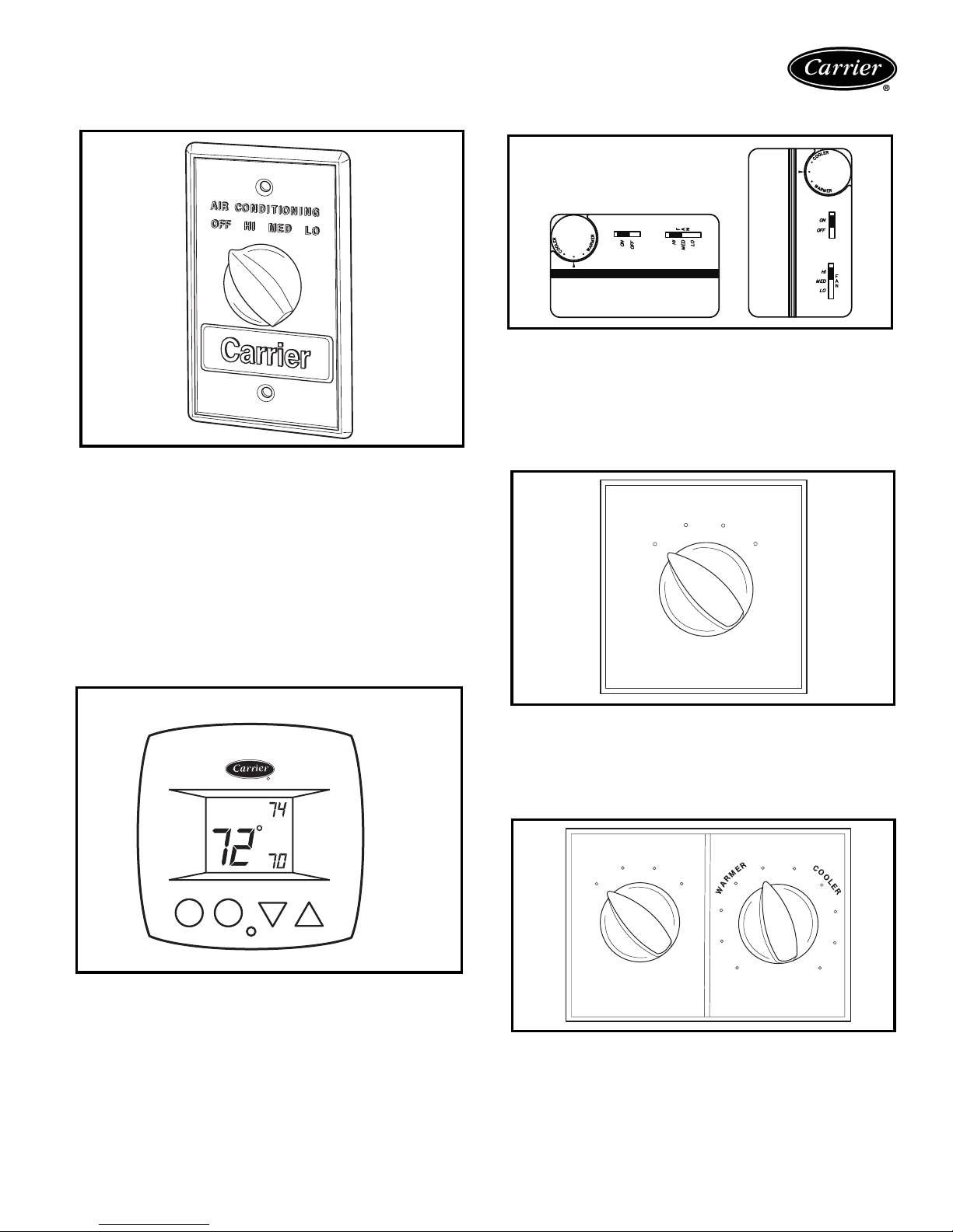
Remote-mounted controls
Standard 3-speed switch — This standard switch has 4
positions: OFF, HIGH, MEDIUM, and LOW. Switch has
auxiliary contact that is energized when switch is in HIGH,
MEDIUM or LOW position.
Some of the options common with the 3-speed switch are:
1. Unit-mounted switch on Furred-In Vertical Model.
(Available as special order on Horizontal Models)
2. Switch without OFF position.
3. Key-operated switch.
Optional remote-mounted thermostat
Line voltage T155 thermostat — Features 50 to 90 F
temperature range, manual 3-speed fan control, mount is a
standard 2 x 4 in. box, 4-pipe, 2-pipe and autochangeover
applications. Available in vertical or horizontal styles.
Unit-mounted controls
MED
HI
F
F
O
LO
Standard remote-mounted thermostat or
optional unit-mounted thermostat
R
COOL
AUTO
HEAT
24-V Debonair® thermostat — Features large Thermoglow™ display, Neverlost™ memory, Exact Fit™ locking
cover, Smart Fan™ dynamic fan speed control, 4-pipe,
2-pipe automatic changeover applications with adjustable
dead band. Programmable and non-programmable models
available.
Standard 3-speed switch — Switch has OFF, HIGH,
MED and LOW positions. Switch is also equipped with
auxiliary connection energized when switch is in HIGH,
MED or LOW position.
MED
HI
OFF
LO
Combination thermostat/3-speed switch — Includes
thermostat for 2-pipe or 4-pipe system and standard
3-speed switch. Thermostat and 3-speed switch are unitmounted in a common electrical junction box. The special
combination allows for the fan coil unit to have control for
the valve cycle only.
11
Controls (cont)
Four-pipe thermostat, model TH104 — With this
thermostat, heating and cooling are sequenced (automatic
changeover) with 6 degree separation between HEATING
ON and COOLING ON. The standard temperature range
is 60 to 90 F.
Two-pipe thermostat, model TF103 — Single-pole
double-throw (SPDT) thermostat has snap action contacts.
The standard temperature range is 60 to 90 F.
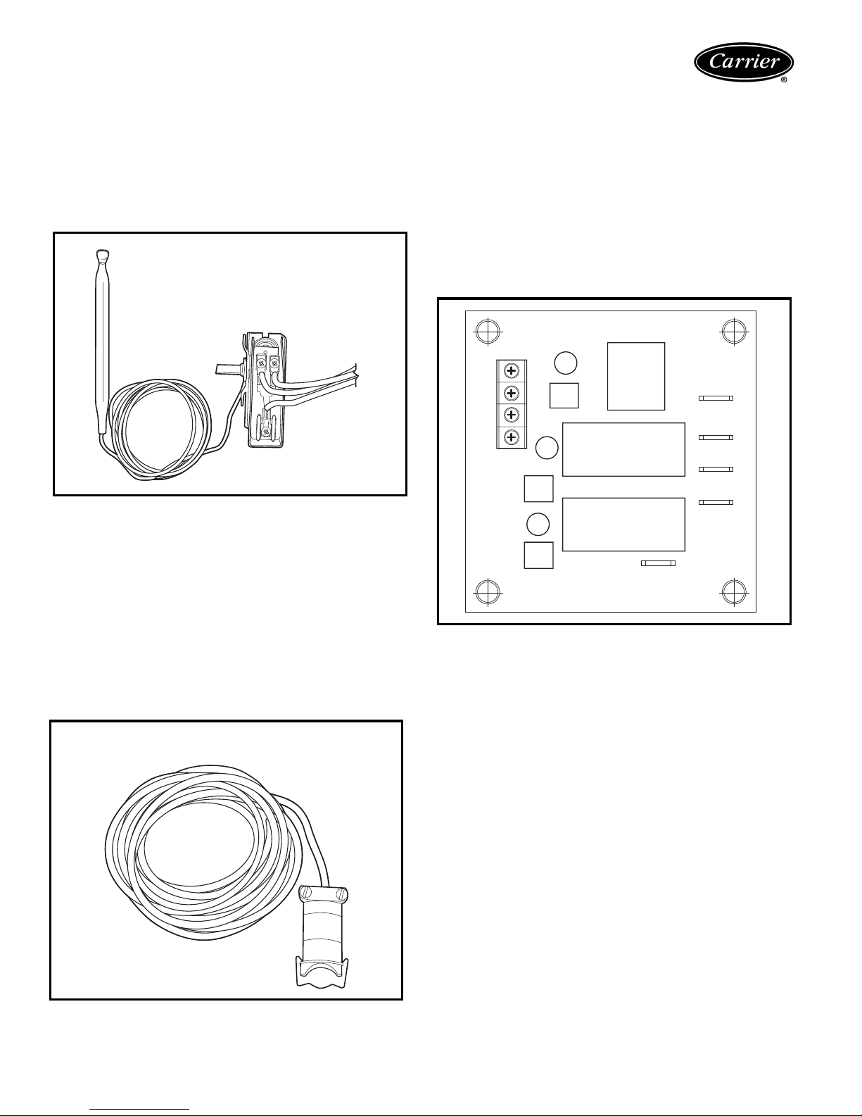
Automatic changeover (Summer-Winter switch) —
The automatic-changeover thermostat is a single-pole
double-throw (SPDT) thermal switch in a moistureproof
and dust-proof enclosure. Thermostat mechanism and lead
ends are hermetically sealed in a polypropylene enclosure
with epoxy resin. Device clamps on coil supply pipe with
end snap-on clip.
The set point temperatures are factory set. When water
temperature rises above 80 F (approximately), the thermostat switches to the winter cycle. When water temperature
drops below approximately 70 F, the thermostat switches
to the summer cycle. Switch reset is automatic.
Fan coil control relay board — The fan coil relay board
is used in conjunction with the Debonair thermostat or a
CCN fan coil controller to regulate a single-speed or multispeed fan. The fan coil relay board can also be used to connect the fan coil controller to a line voltage valve actuator.
The fan coil relay board is factory shipped as a PC board
with four
1
/2-in. stand-offs attached for field mounting.
NOTE: One fan coil relay board is used for each application. Fan coils with two or more fan motors use a fan coil
relay board for each fan motor. A maximum of three fan
coil relay boards can be wired to one fan coil control.
G
G2/(W)
G3/(Y)
COM
FAN
(VALVE)
(COOL)
HI
(HEAT)
MED
LO
AUTOMATIC CHANGEOVER
(Summer-Winter) SWITCH
12
STEMCO
416-79
L80 8220
Application data
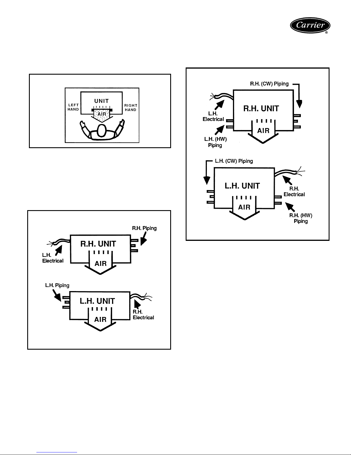
Basic definitions
Unit hand — When facing the supply air outlet from the
front of the unit (air blowing in your face), your right hand
will be the right hand side of the unit and your left hand the
left hand side of the unit.
UNIT HAND
Same end connection (2 pipe or 4 pipe) — All piping
connections are on the same end (side) of the unit. Controls and electrical connection will be on the end (side)
opposite the piping connection.
Standard 2-pipe units will be the same end connection.
Opposite end connection (4-pipe option) — Hot
water (HW) piping connections and electrical will be on the
end (side) opposite the chilled water (CW) and drain
connections.
OPPOSITE END CONNECTION
SAME END CONNECTION
NOTE: Piping determines the hand of the unit.
NOTE: Chilled water piping determines the hand of the unit.
13
Application data (cont)
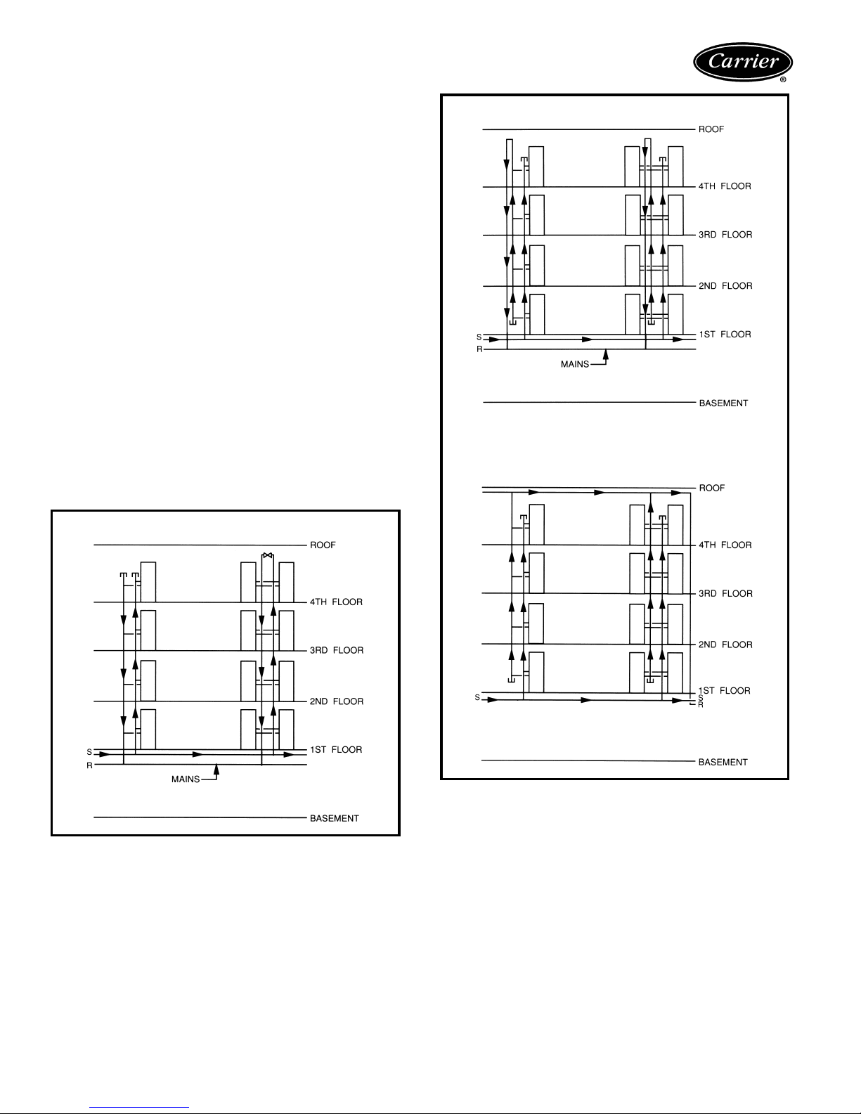
System piping
The following diagrams show some common methods
used to pipe the 42S series units. Only the 2-pipe systems
are shown; however, the methods would be the same for
4-pipe systems.
System 1, the “direct return” system, is the most common.
It is economical to install since it supplies and returns the
water for a riser column from the same location, at the top
or the bottom of a building. This type of riser arrangement
does require more attention to individual unit water flow
balancing. The risers are normally capped at the end as
shown in the diagrams.
System 2, the “reverse return” system, is used to minimize
the requirement for individual unit balancing. This system
is usually referred to as the self-balancing system. The
arrangement of the risers allows the water flow for each
unit in a column to be equalized. In the reverse return system both the supply and return mains are located at the
top or the bottom of a building requiring an additional
return riser to be furnished in the units.
System 3, the “common reverse return” system, typically
has the supply and return mains located remotely from
each other — such as one at the top and one at the bottom
of a building. This eliminates the need for a reverse return
riser in the units.
SYSTEM 2 — REVERSE RETURN
SYSTEM 3 — COMMON REVERSE RETURN
SYSTEM 1 — DIRECT RETURN
14
Risers
Riser diameter is an important consideration in the design
of stack series systems. Standard units can accommodate
3
/4-in. to 21/2-in. riser sizes in 2-pipe systems. For other
applications, such as reverse return risers or 4-pipe systems, it may be necessary to accommodate the additional
risers.
Riser size is based on the water flow needed for a given
tier of units. Unit risers are sized according to the diameter
and length requirements as specified by the customer. To
determine riser size, water velocity should be limited to 5 to
8 ft/second. Thus, if 10 units are to be stacked vertically
with each unit requiring 3 gpm, the maximum flow in the
risers is 30 gpm. Through 1
of 7.5 ft/second. The maximum flow rate of 30 gpm
occurs only at the supply and return points. As the water
moves upward, the flow in the supply riser is reduced by
3 gpm per floor, so that after 3 floors, the total flow is
21 gpm and riser size can be reduced to one inch. See
chart on page 103.
1
/4 in. risers, this is a velocity
Condensate drains are available in sizes down to one
inch for greater first cost economy.
Riser size-reducers are factory installed and caps are pro-
vided at customer request.
For risers of over 115 in. length, filler pieces can be fur-
nished for field installation.
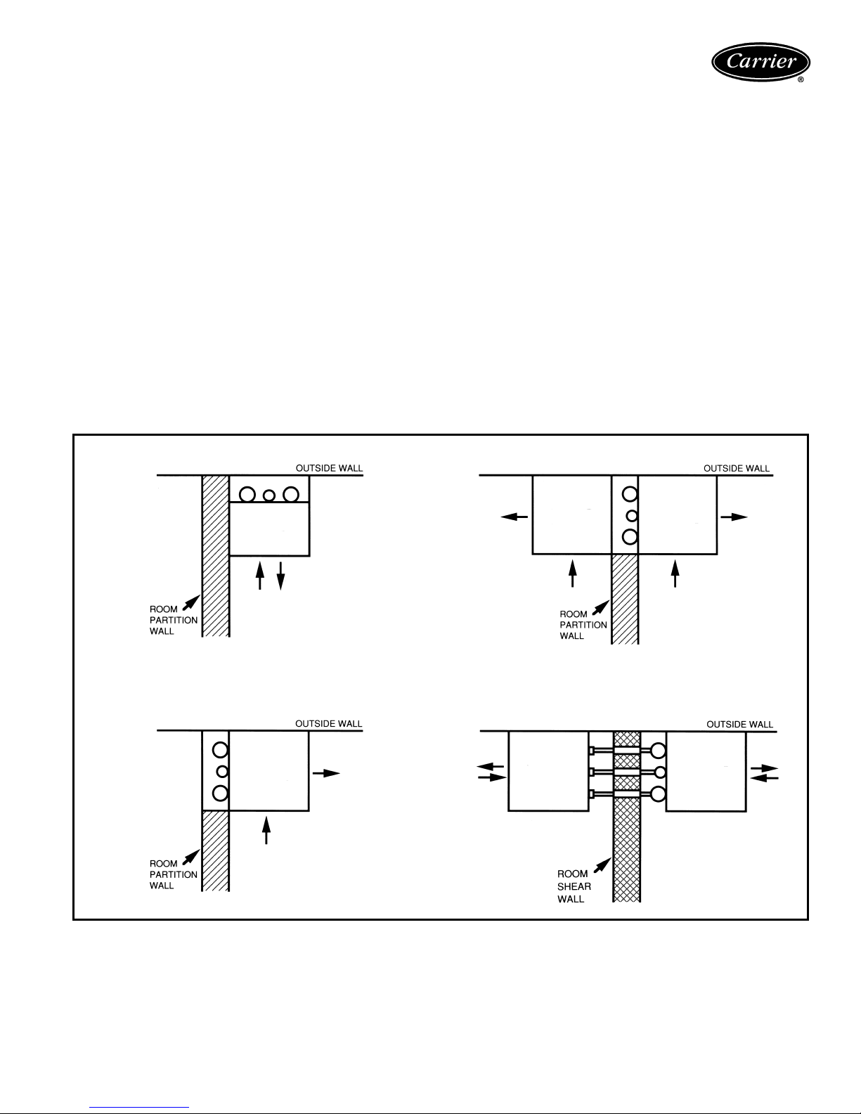
Typical arrangements
Typical arrangement applications for each model type are
shown below. The fan coil units feature almost an unlimited number of arrangements to meet the needs of new
construction, renovation, or reconstruction. Consult the
factory for the arrangement (standard or special) to meet
your particular need.
42SH — EXPOSED CABINET
42SG — FURRED-IN STACK
42SJ — BACK-TO-BACK FURRED-IN STACK
42SG — FURRED-IN STACK MASTER/SLAVE UNIT
15
Application data (cont)
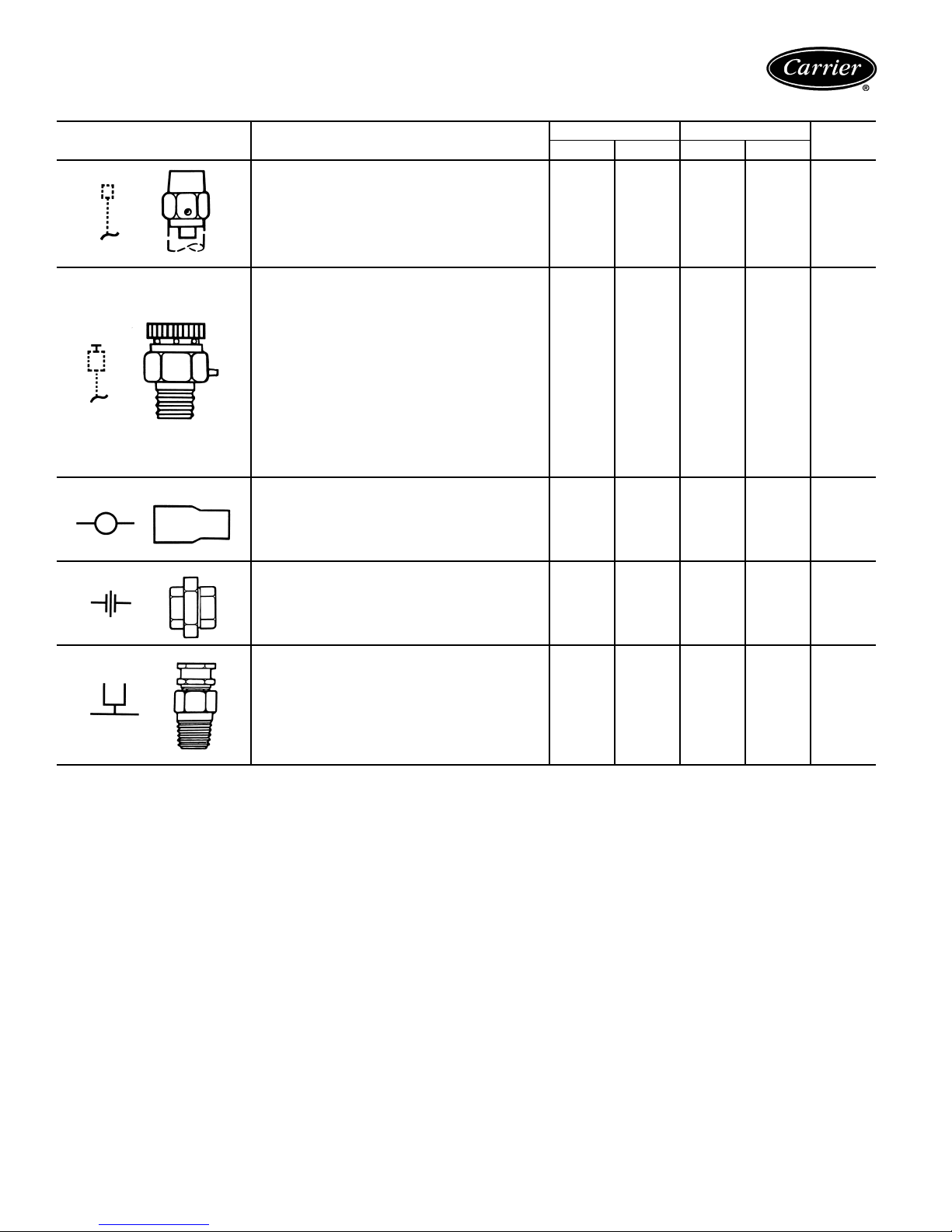
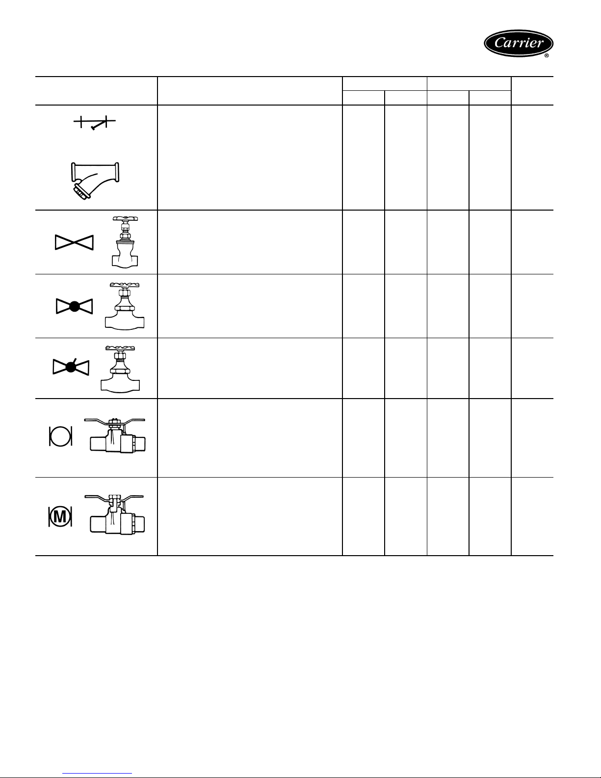
PIPING COMPONENTS
SYMBOL/SKETCH DESCRIPTION
MANUAL AIR VENT: Threaded brass needle
valve with screwdriver slot for adjustment.
Application — Body brazed into high point of
heating and cooling coils for bleeding air from
coil. Standard item on all hydronic coils (not
used on steam or DX coils). Should not be
used in lieu of main system air vents.
AUTOMATIC AIR VENT: Nickel plated brass
valve, fiber-disc type, with positive shut-off
ballcheck and quick vent feature via knurled
vent screw.
Application — Optional replacement for manual air vent. Automatically passes minute
quantities of air through the fiber discs which
expand upon contact with water, completely
sealing the valve. As air accumulates, the fiber
discs dry and shrink, repeating the cycle. Not
recommended for removing large quantities of
air encountered during initial start-up or subsequent draining and refilling. Should not be
used in lieu of main system air vents.
SWAGE: Copper tube end expanded to accept
a copper tube of the same size for factory or
field brazing.
Application — Used where possible for all tubing joints for best joint integrity.
UNION: Combination wrought copper/cast
brass union assembly, solder by solder.
Application — Used for quick connect (and disconnect) of valve package components to minimize field labor and facilitate servicing of unit.
INSERTION TEST PORT: Brass body valve
for acceptance of test probe (up to
diameter).
Application — Installed on one (or both) sides
of the coil to allow for temperature or pressure
sensing. Used for close tolerance water balancing and service analysis.
1
/8in.
CVFACTOR RATING*
1
/
2
3
/
4
PSI F
STEAM
USE
N/A N/A 400 100 NO
N/A N/A 125 240 NO
N/A N/A 300 200 YES
N/A N/A 300 200 YES
N/A N/A 250 250 NO
LEGEND
Cv — Coefficient of Velocity
DX— Direct Expansion
*Check all system component pressure ratings (coils, values, pumps,
etc.) with manufacturer and any applicable local or national piping
codes prior to specifying system pressure rating.
16
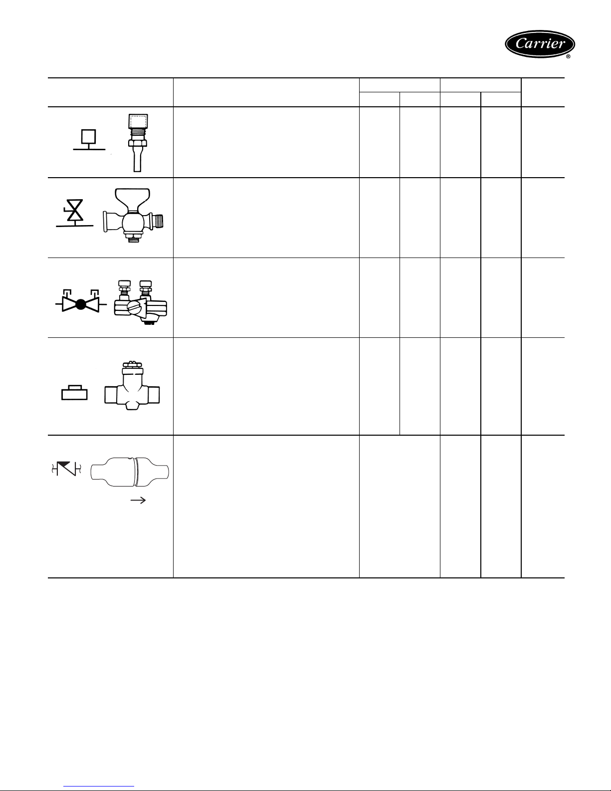
PIPING COMPONENTS (cont)
SYMBOL/SKETCH DESCRIPTION
PRESSURE TEST PORT: Brass body
vice access fitting with removable depressor
type core.
Application — Installed on both sides of the
coil to allow for pressure sensing. Attach
pressure gages to facilitate close tolerance
water balancing.
GAGE COCK: Brass shut-off valve with
1
/4FPT fitting for attachment of pressure
gages.
Application — Installed on both sides of the
coil to allow for pressure sensing. Attach
pressure gages to facilitate close tolerance
water balancing. May be used in bleed
bypass line to regulate water flow.
CIRCUIT SETTER: Variable water flow balancing valve with manual adjustment knob,
pointer, percent-open scale, memory stop
and integral pressure read-out ports.
Application — Used for close tolerance water
flow balancing. Positive shut-off ball valve
feature allows usage as combination balancing and shut-off valve.
BALANCE VALVE: Varia ble water flow man ual balancing valve with screwdriver slot
adjustment screw.
Application — Often used in conjunction with
test port fittings for water flow balancing. Balance by temperature differential or coil pressure drop (check specifications for service
fittings required if balancing by pressure
drop). May be used in 3-way valve bypass
line to permit equal flow balancing.
FIXED FLOW VALVE: Flexible orifice type
(non-adjustable).
Application — Used for water flow balancing.
Valve automatically adjusts the flow to within
10% of set point. Requires 15 psi
(35 ft) of additional pump head for proper
FLOW
operation.
1
/4ser-
C
FACTOR RATING
V
1
/
2
3
/
4
PSI F
N/A N/A 400 210 NO
N/A N/A 200 250 N/A
2.12 3.9 300 250 NO
3.0 8.9 150 200 NO
Valve orifice size
determines C
V
factor. The orifice of
these fixed flow
valves changes as
flow is regulated.
As the water pressure increases,
the orifice size
150 160 NO
decreases,
thereby automatically limiting the
flow rate to the
specified gpm
(±10%).
STEAM
USE
LEGEND
Cv — Coefficient of Velocity
DX— Direct Expansion
17
Application data (cont)
PIPING COMPONENTS (cont)
SYMBOL/SKETCH DESCRIPTION
STRAINER: Y-type body with 50 mesh stain-
less steel screen.
Application — Used for removal of small parti-
cles from system water during normal system
operation. Should not be used in lieu of main
system strainers. Strainer screen may have to
be removed during initial high pressure system flushing during start-up. Screen should be
removed and cleaned per normal maintenance schedule (provisions for strainer blowdown not provided).
GATE VALVE: Manual shut-off valve.
Application — Used for unit isolation during
system flushing, servicing, etc. Do not use for
water balancing.
GLOBE VALVE: Standard pattern, manual
shut-off and throttling valve.
Application — Used for unit isolation. Not recommended for high flow rates due to relatively
high pressure drop.
C
FACTOR RATING
V
1
/
2
9.0
Clean
3
/
4
19.0
Clean
PSI F
400 250 N/A
STEAM
USE
19.8 36.0 200 200 NO
1.8 3.9 200 200 NO
LEGEND
Cv — Coefficient of Velocity
DX— Direct Expansion
COMPRESSION STOP VALVE:
Manual shut-off valve.
Application — Used for unit isolation during
system flushing, servicing, etc. Not recommended for high flow rates due to relatively
high pressure drop.
BALL VALVE: Manual balance and shut-off
valve.
Application — Used for unit isolation and
water flow balancing. Without memory stop
feature water balance point must be marked
by installer (if necessary). Check specifications for service fittings required when used
for water balancing.
BALLVALVEWITHMEMORYSTOP:
Manual balance and shut-off valve.
Application — Used for unit isolation and
water flow balancing. The adjustable memory
stop feature allows return to the balance point
after shut-off. Check specifications for
service fittings required when used for water
balancing.
2.3 5.4 150 200 NO
4.0 7.5 400 200 YES
4.0 7.5 400 200 N/A
18
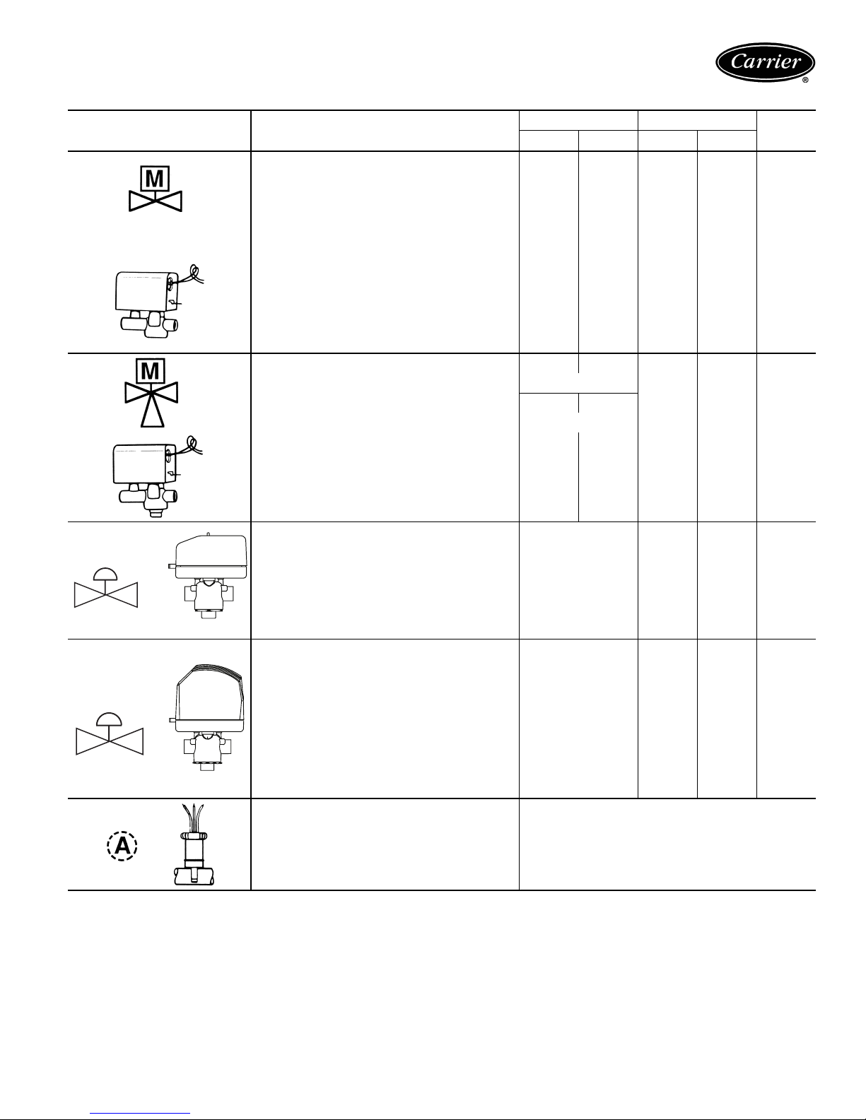
PIPING COMPONENTS (cont)
SYMBOL/SKETCH DESCRIPTION
2-WAY MOTORIZED VALVE: Electric 2-posi-
tion flow control valve (open/closed). Normally
closed body with manual override lever.
Installedinsupplylinetounit.
Application — All standard control and valve
packages are based upon normally closed
valves (valve electrically powered open and
closed by spring return when electric power
removed). Manual override lever allows valve
to be placed in the open position for secondary (unit) flushing, constant water flow prior to
start-up, etc. Manual override is automatically
disengaged when valve is electrically activated. Consult factory for normally open
valve applications.
3-WAY MOTORIZED VALVE: Electric
2-position flow control valve (closed to coil/
open to bypass or open to coil/closed to
bypass). Normally closed with manual override lever. Installed in supply line to unit.
Application — Same comments as 2-way
motorized valve except with manual override
lever engaged the valve is open to both ports
and water flow will take the path of least resistance through the valve package (not necessarily 100% through the coil).
C
FACTOR RATING
V
1
/
2
3
/
4
PSI F
2.3 2.3 300 200
5.0 5.0
SERVICE
2.8 2.8
BYPASS
300 200 N/A
STEAM
USE
YES
15
PSI
MAX.
MODULATING VALVE
(Non-Spring Return): Modulating valves are
designed to control the flow in the circuit by
making incremental adjustments to the flow
path within the valve.
Application — To control fluid flow in fan coil
units.
MODULATING VALVE
(Spring Return): Modulating valves are
designed to control the flow in the circuit by
making incremental adjustments to the flow
path within the valve.
Application — Same comments as non-spring
return except when powered, the actuator
moves to the desired position, at the same
time tensing the spring return system. When
power is removed for more than two minutes
the spring returns the actuator to the normal
position.
AQUASTAT: Water temperature sensing electrical switch.
Application — Clips directly on nominal
1
/2in. or3/4in. copper tubing for water
size
temperature sensing. Must be correctly
located for proper control operation.
LEGEND
Cv — Coefficient of Velocity
DX— Direct Expansion
NOTES:
1. Motorized 2-way valves have a maximum close-off differential of 25 psi.
2. Motorized 3-way valves have a maximum close-off differential of 10 psi.
4.0
4.0
300 200 N/A
300 200 N/A
19
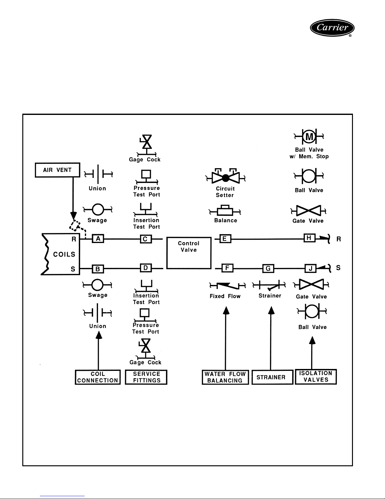
Application data (cont)
Valve p acka g es
There are limitations on physical size of pneumatic valves,
quantity and type of matching components, and required
control interface. See Symbols and Placement of Valves
diagram.
Consult factory before ordering any special valve pack-
age components that are not covered in this book.
SYMBOLS AND PLACEMENT OF VALVES
Valve packages are shipped with the units or in unit cartons. Valve packages include belled ends for field soldering
to coil connections.
All factory-furnished cooling valve packages are
arranged to position as much of the package as possible
over an auxiliary drain pan or drip lip. This helps minimize
field piping insulation requirements.
Coil Connections (Positions A & B) — When isolation valve only is added to supply or return line, the isolation valve will be factory
brazed to the coil stub-out. Addition of any other component or connection to the supply or return line will change the respective coil
connection(s).
Service Fittings (Positions C & D) — Optional fittings for attaching pressure/temperature sensing devices to obtain pressure drop or temperature differential across coil. Used with ball valve or balance valve where extremely accurate water flow balancing is required.
Water Flow Balancing (Positions E, F, & H) — Only one device per total valve package to be used for balancing water flow through the
coil. When isolation valve (ball valve or ball valve with memory stop at position H) is used for water flow balancing, do not specify additional
balancing device at position E or F. When balancing device is specified at position E or F, isolation valve does not require balancing feature
at position H (with a 3-way motorized valve, a bypass balancing valve may be specified in the bypass line to permit equal flow balancing).
Strainer (Position G) — Does not include blow down fitting and should not be used in lieu of main piping strainers.
Isolation Valves (Positions H & J) — Normally requires one each on supply and return line (see exception under circuit setter). When
position H is used for balancing (ball valve or ball valve with memory stop), check specifications for service valve requirements.
20
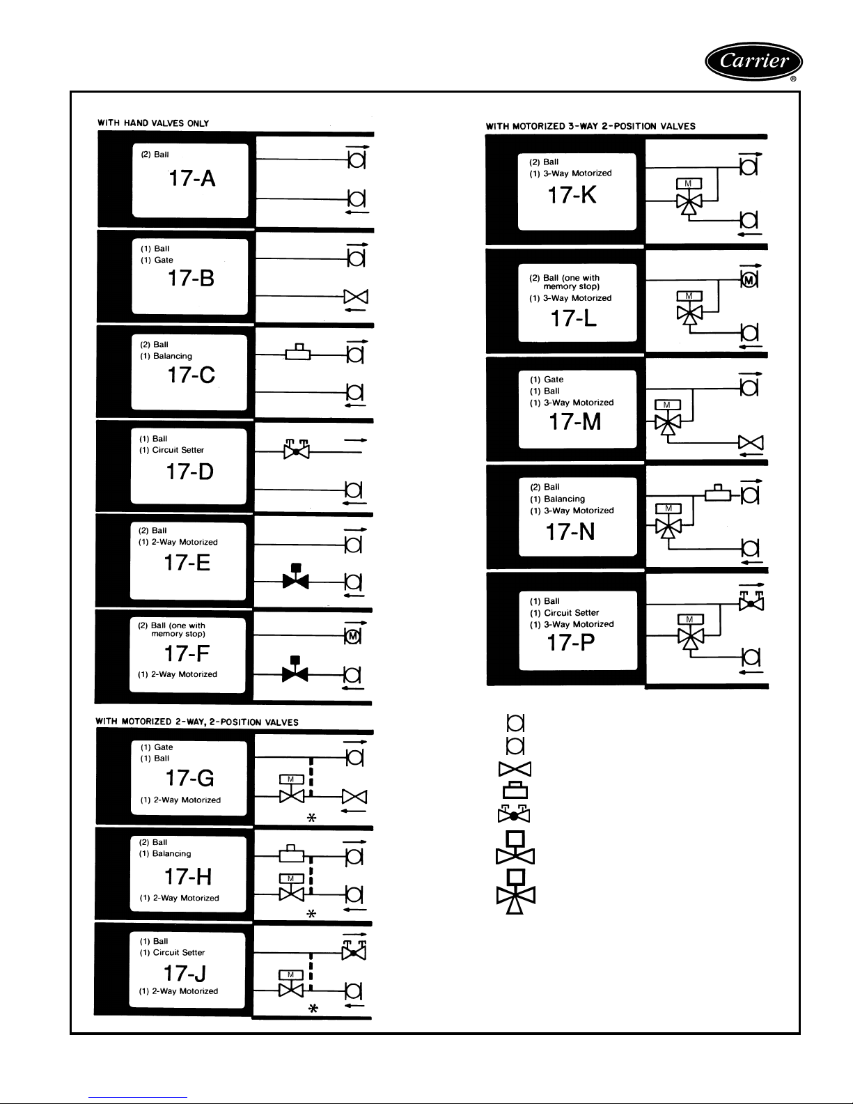
VALVE PACKAGE ARRANGEMENTS
LEGEND
Ball Valve
M
Ball Valve with Memory Stop
Gate Shut Off Valve
Balancing Valve
Circuit Setter
M
Motorized 2-Way Valve
M
Motorized 3-Way Valve
*When aquastat is used for automatic changeover, bypass is
required as indicated by dashed line.
NOTES:
1. Packages factory furnished and installed.
2. Valves are
3. If an automatic flow control valve is added, it will be located on
supply line between shutoff valve and coil (or motorized control
valve, if supplied).
4. Packages 17-A,B,C,D,E,F,G,H,J,K,L,M,N and P are listed on
current price pages.
5
/8-in. ODS unless otherwise specified.
21
Application data (cont)
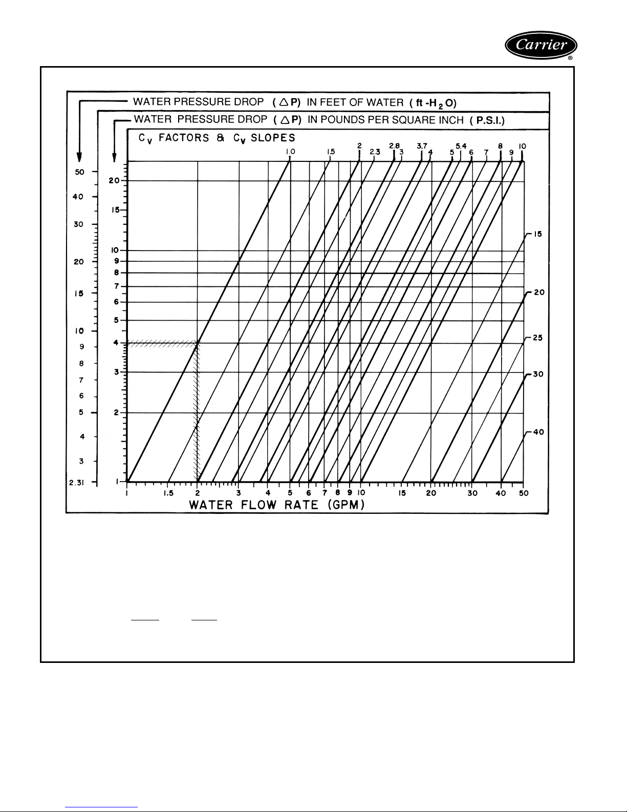
Cv FACTOR VS WATER PRESSURE DROP
CVFAC TOR :
The flow rate in gallons per minute (gpm) through a piping component when the pressure drop (∆P) in pounds per square inch (psi)
across the component is 1.0 (psi).
Pressure drop (ft-H
O) = 2.31 x psi (pressure drop)
2
GRAPH EXAMPLE:
∆P for 2.0 gpm through a component with a C
FORMULA EXAMPLE:
∆P(ft-H
O) =
2
(gpm)
(C
v
2
2
)
x2.31=
(2.0)
(1.0)
2
2
TOTAL PRESSURE DROP is the Sum of the pressure drop of all piping and components in the water flow path.
22
of 1.0 is 4.0 psi x 2.31 = 9.24 ft-H2O
V
x 2.31 = 9.24 ft-H2O

ENTHALPY AT SATURATION
TEMPERATURE
(F)
40 15.230 60 26.46
41 15.697 61 27.15
42 16.172 62 27.85
43 16.657 63 28.57
44 17.149 64 29.31
45 17.650 65 30.06
46 18.161 66 30.83
47 18.680 67 31.62
48 19.211 68 32.42
49 19.751 69 33.25
50 20.301 70 34.09
51 20.862 71 34.95
52 21.436 72 35.83
53 22.020 73 36.74
54 22.615 74 37.66
55 23.22 75 38.61
56 23.84 76 39.57
57 24.48 77 40.57
58 25.12 78 41.58
59 25.78 79 42.62
ENTHALPY AT
SATURATION
(Btu per lb.
of dry air)
TEMPERATURE
(F)
80 43.69
ENTHALPY AT
SATURATION
(Btu per lb
of dry air)
ALTITUDE COOLING CORRECTION FACTORS STEAM PRESSURE CORRECTION FACTORS
ELEVATION (ft) TOTAL HEAT SENSIBLE HEAT
1000 .990 .960
2000 .980 .930
3000 .970 .896
4000 .960 .864
5000 .940 .830
6000 .930 .800
7000 .920 .770
8000 .910 .750
9000 .900 .730
ENTERING AIR
TEMP (F)
40 1.202 1.265
50 1.134 1.196
60 1.067 1.125
70 1.000 1.054
NOTE: Steam Heating Capacity (Btuh) = Base Capacity x Pressure
Correction Factor x SH (SH value found in Cooling Capacity Correction
Factors table on page 60).
STEAM PRESSURE (PSIG)
25
AIRFLOW CORRECTION FACTORS
CFM RATIO
(Actual/Base)
1.40 1.25 1.26
1.35 1.22 1.23
1.30 1.19 1.20
1.25 1.16 1.17
1.20 1.13 1.14
1.15 1.10 1.11
1.10 1.07 1.08
1.05 1.04 1.04
1.00 1.00 1.00
0.95 0.97 0.97
0.90 0.94 0.93
0.85 0.90 0.89
0.80 0.86 0.85
0.75 0.82 0.81
0.70 0.78 0.77
0.65 0.74 0.72
0.60 0.70 0.67
0.55 0.66 0.62
0.50 0.62 0.57
0.45 0.58 0.52
0.40 0.53 0.47
0.35 0.48 0.42
0.30 0.43 0.38
0.25 0.38 0.33
LEGEND
CFM — Cubic Feet per Minute
Cs — Sensible Airflow Correction Factor
Ct — Total Airflow Correction Factor
ESP — External Static Pressure
TOTAL (Ct) SENSIBLE (Cs)
23
Application data (cont)
Electric heat
Electric heaters are available for installation on Carrier fan
coil units in the following applications.
Total electric heat — This system provides complete
heating during the heating season; no boiler is required.
Heating and cooling are now available on an individual
basis throughout the year with a 2-pipe system.
Chilled water is used for cooling and the electric heater is
used for heating. Individual room controls can be supplied
for either manual or automatic changeover.
Auxiliary electric heat — This system is used for heating between seasons or during the cooling season when
chilled water is being circulated. Individual room controls
are supplied to provide electric heat only when chilled
water is being circulated through the system. Water flow
through the unit is shut off when the heater is turned on.
During the winter heating season, heating is provided by
hot water circulated through the system. A changeover
device locks out the electric heat when the hot water is
circulated.
Heater construction
Strip heaters are used with Model 42C ceiling units,
Model 42D ducted units and Model 42S stack units.
These heaters consist of coils of the highest grade resistance wire, insulated by ceramic insulators in aluminized
brackets.
All heaters except those used in 42S stack units are positioned on the incoming (preheat) side of the unit coil. On
42S stack units, the strip heater is located in the fan discharge on the leaving side of the coil.
Sheath heaters are used with Model 42V vertical units.
These heaters consist of the highest grade resistance wire,
centered in a
The wire is insulated from the sheath by magnesium oxide
powder packed around it. To increase the heater surface
exposed to air, a 1
wound around the sheath in a continuous spiral that makes
5 turns per lineal inch. Sheath and fin are permanently
bonded together by copper brazing.
The heaters are positioned on the leaving (reheat) side of
the unit coil. On special units with high efficiency motors, a
strip heater will be installed in the fan discharge on the
incoming (preheat) side of the unit coil.
1
/2-in. diameter copper-plated steel sheath.
1
/4-in. OD fin of copper-plated steel is
Heater electrical data
1. Load voltage may be 120, 208, 240 or 277 volts. For
unit size and kW limitations, refer to the specific unit
catalogs.
2. All heaters are single stage and single phase.
3. Unless a single power-source option is selected, the
electric heat units require 2 separate power sources.
With the single power-source option, only one line circuit need be brought into the unit. Fuse protection is
added to the motor/control circuit to protect these
components. This is separate from the field-furnished
total unit overcurrent protection.
MODEL 42V VERTICAL UNIT
WITH ELECTRIC SHEATH HEATER
MODEL 42C CEILING UNIT
WITH ELECTRIC STRIP
HEATER
24
42C SERIES
42D SERIES
HEATER
VOLTAGE
120
208,
240,
277
240,277 10.0 34,150 *
CAPACITY
kW
(Btuh)
0.5 1,708 * *
1.0 3,415 * * *
1.5 5,123 * *
2.0 6,830 * * * * * * *
3.0 10,245 * * * *
0.5 1,708 * *
1.0 3,415 * * *
1.5 5,123 * *
2.0 6,830 * * * * * * *
3.0 10,245 * * * *
4.0 13,660 * * * *
5.0 17,075 * *
6.0 20,490 * * * *
8.0 27,320 * *
02 03 04 06 08 10 12
UNIT SIZE
42V SERIES
HEATER
VO LTAGE
120
208,
240,
277
240,277 6.0 20,490 *
NOTE: All heaters are single-stage and single-phase. Contact your
Carrier representative for heater availability for 220-1-50 units.
CAPACITY
kW
0.5 1,708 * *
1.0 3,415 * * * *
1.5 5,123 * * *
2.0 6,830 * * *
3.0 10,245 ****
1.0 3,415 * * * *
1.5 5,123 * * *
2.0 6,830 * * *
3.0 10,245 ****
4.0 13,660 * * *
5.0 17,075 * *
(Btuh)
02 03 04 06 08 10 12
UNIT SIZE
HEATER
VO LTAGE
120
208,
240,
277
NOTE: All heaters are single-stage and single-phase.
CAPACITY
kW
(Btuh)
2.0 6,830 * * *
3.0 10,245 * * *
2.0 6,830 * * *
3.0 10,245 * * *
4.0 13,660 ********
5.0 17,075 *******
6.0 20,490 *******
7.0 23,905 ******
8.0 27,320 *****
9.0 30,735 *****
10.0 34,150 ****
12.0 40,980 * * *
14.0 47,810 *
06 08 10 12 14 16 18 20
UNIT SIZE
42S SERIES
HEATER
VOLTAGE
120
208
240,
277
kW
10.0 * *
03 04 06 08 10 12
1.0******
1.5******
2.0******
3.0******
1.0******
1.5******
2.0******
3.0******
4.0 *****
5.0 ****
6.0 ***
8.0 ***
1.0******
1.5******
2.0******
3.0******
4.0 *****
5.0 ****
6.0 ***
8.0 ***
UNIT SIZE
25

Selection procedure
Refer to the Carrier Electronic Selection Program for information to determine unit sizing for your needs. The following selection procedure applies to all Carrier 42 series
units and may be used as a guide to determine unit
performance.
FORMULAS
TC = TC
SC = SCb x Cs x E
x Ct x E
b
t
s
Where:
C
= Sensible Airflow Correction Factor
s
C
= Total Airflow Correction Factor
t
= Sensible Elevation Correction Factor
E
s
E
= Total Elevation Correction Factor
t
SC = Sensible Capacity
= Base Sensible Capacity from Base Cooling
SC
b
Capacities by Gpm charts
TC = Total Capacity
TC
= Base Total Capacity from Base Cooling
b
Capacities by Gpm charts
QUICK SELECTION
EXAMPLE:
To rate the performance at sea level for a 42DCA06 unit
with four-row coil at 80 F/67 F EAT, 45 F EWT, and
10 gpm water flow at high speed fan with 0.25 in. wg
ESP:
1. Enter the Base Cooling Capacities by Gpm, Standard
Capacity Units (Four Row) table on page 77 at 80 F/
67 F EAT and 45 F EWT.
2. Locate the appropriate row for unit size 06 and
10 gpm.
Record the tabulated base performance.
TC
= 21.5 MBtuh
b
SC
= 15.2 MBtuh
b
∆T = 4.3° F
3. Select the actual cfm from the Air Delivery table on
page 82.
Record actual cfm for 42DCA06 with four-row coil
with high speed and 0.25 in. wg ESP.
Cfm Actual = 580
4. Divide Cfm Actual by Cfm Nominal to determine Cfm
Ratio.
Cfm Ratio = 580/600 = .967
5. Select the cfm correction factors, C
and Cs, from the
t
Airflow Correction Factors table on page 23. (Interpolation may be required.)
C
= 0.98
t
= 0.98
C
s
6. Select the elevation correction factors, E
and Es, from
t
the Altitude Correction Factors table on page 23.
E
= 1.00
t
= 1.00
E
s
7. Calculate actual performance.
TC = TC
x Ct x E
b
t
= 21.5 x 0.98 x 1.00
= 21.1 MBtuh
SC = SC
x Cs x E
b
s
= 15.2 x 0.98 x 1.00
= 14.9 MBtuh
8. Calculate water pressure drop. From the Cv Factor by
Coil and Unit Size table on page 86, find the Cv value
for unit size 06 with four rows.
Cv = 4.00
∆P = [GPM/(0.658 x Cv)
= [10.0/(0.658 x 4.00)
2
2
= 14.4 feet of H2O
26
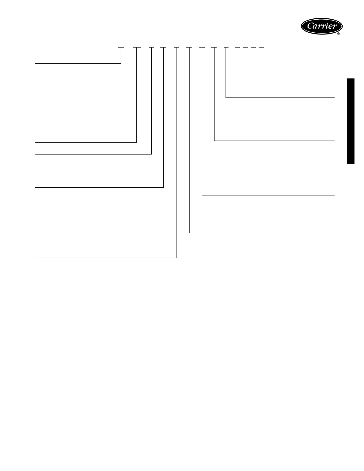
Model number nomenclature
42CAA03ARCY5––––
42 – Series Fan-Coil Unit
Model
Vertical Units
VA – Furred-In
VB – Cabinet
VC – Furred-In Lowboy
VE – Cabinet Lowboy
VF – Slant-Top Cabinet
VG – Furred-In Wall Unit
Ceiling Units
CA – Furred-In
CE – Furred-In with Plenum
CF – High Static, Furred-In
CG – Cabinet
CK – Telescoping Bottom Panel
Design Series (A or B*)
Unit Size (Airflow, cfm)
01 – 150 (42VG Only) 06 – 600
02 – 200 08 – 800
03 – 300 10 – 1000
04 – 400 12 – 1200
Coil
A–3 Row (Standard)
2 Row (VC, VE, VG Standard)
B–4 Row High Capacity
3 Row High Capacity (VC, VE Only)
C–3/1 Opposite End Connection
2/1 Opposite End Connection (VC, VE Only)
D–3/1 Same End Connection
2/1 Same End Connection (VC, VE Only)
E–3/2 Opposite End Connection
F–3/2 Same End Connection
G–4/1 Opposite End Connection
H–4/1 Same End Connection
Arrangement
42V:
5–Front Return, Top Supply
7–Front Return, Front Supply
42C:
5–Bottom Return, Front Supply
6–Rear Return, Front Supply
Electric Heaters
Y–None
A-Z, 1 – 42V
A-Z, 1-9 – 42C
Motor
C–120V Permanent Split Capacitor (PSC) (Standard)
D–208/1/60 PSC
E–230/1/60 PSC
F–277/1/60 PSC
V–220/1/50 PSC
Hand
R–Right
L–Left
42C,V Series Units
*Model 42CG only.
27
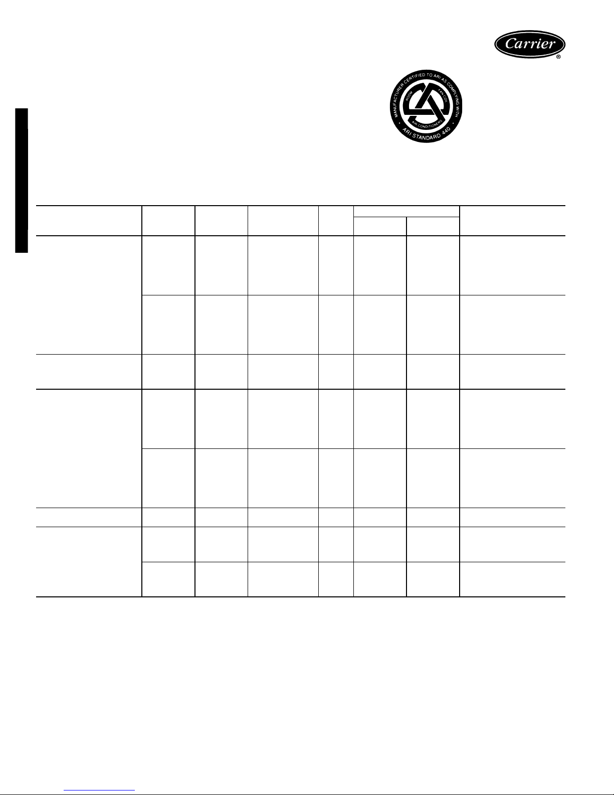
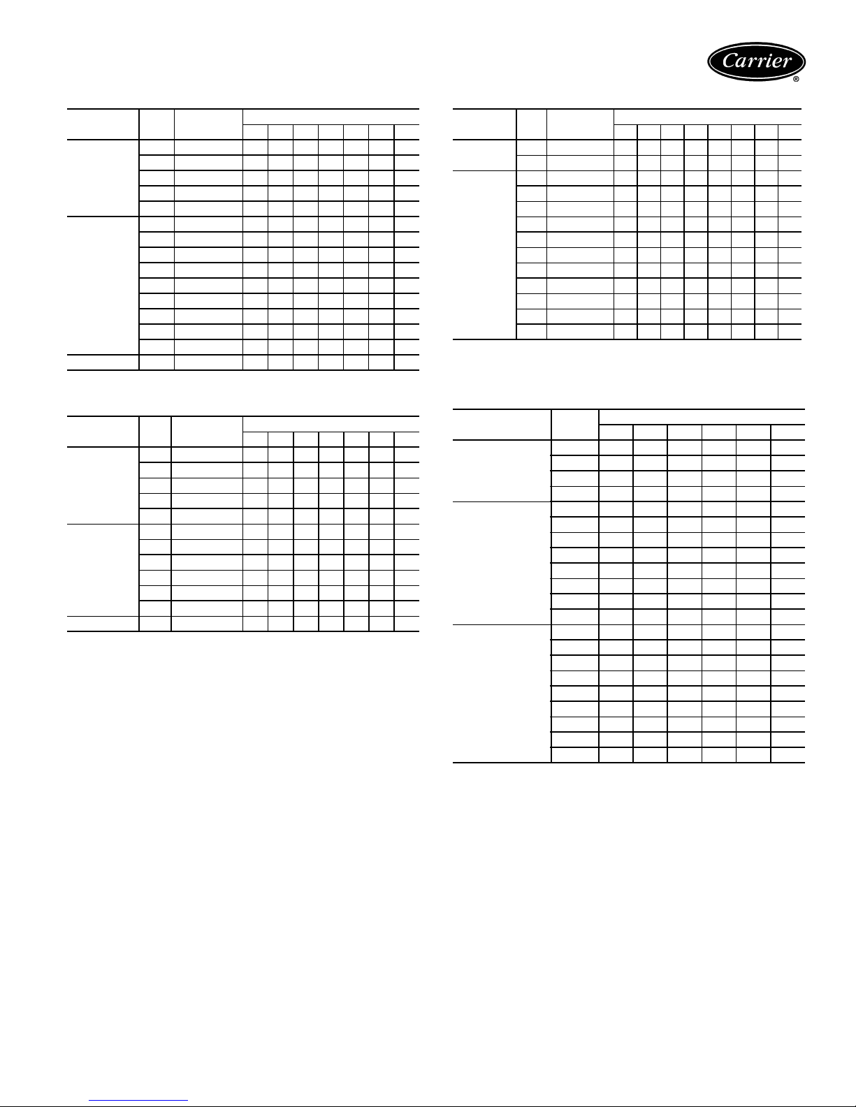
ARI capacity ratings
The 42C, V series fan coil units are certified in compliance
with the Air Conditioning and Refrigeration Institute (ARI)
Industry Standard 440-98 for room fan coil units. Approved standard ratings are tabulated below:
ARI APPROVED STANDARD RATINGS*
42C,V Series Units
GPM — Gallons per minute
MBtuh — Capacity (Btuh in thousands)
*Ratings based on motor at high fan speed, standard air and dry coil oper-
ation, 10° F water temperature rise; entering-air temperature 67 F wb;
80 F db; entering water temperature 45 F.
†Motor type permanent split capacitor operating at 115-1-60 voltage.
**Shaded pole motor.
UNIT
42CA,CE,CG,CK
42CF
42VA,VB,VF
42VG
42VC,VE
LEGEND
UNIT
SIZE
02
03 300 1.8 9.0 6.9 85
04 400 2.5 13.3 10.3 165
06 600 3.6 18.0 14.6 225
08 800 4.6 22.6 16.9 235
10 1000 5.5 27.5 21.0 305
12 1200 6.6 32.8 25.0 435
02
03 300 2.1 9.8 6.5 85
04 400 2.8 13.8 9.8 145
06 600 4.0 19.6 14.3 220
08 800 5.1 25.5 18.8 235
10 1000 6.2 31.0 23.0 300
12 1200 7.5 37.2 27.7 425
04
06 600 4.4 21.8 16.0 205
08 800 5.3 26.5 19.6 225
10 1000 7.5 37.2 27.6 355
02
03 300 1.5 7.2 5.3 80
04 400 2.4 11.2 7.9 130
06 600 3.0 13.9 10.4 180
08 800 4.0 19.1 13.5 210
10 1000 4.8 22.0 16.8 240
12 1200 5.3 26.3 20.0 370
02
03 300 2.0 9.9 7.0 80
04 400 2.7 13.1 8.6 130
06 600 3.8 18.6 13.6 170
08 800 4.2 20.6 14.1 195
10 1000 5.9 29.5 19.6 240
12 1200 7.8 35.3 26.3 370
01
03 300 1.5 5.2 4.7 225**
02
03 300 2.0 8.6 6.7 135
04 400 2.6 12.3 8.3 150
06 600 3.6 18.3 13.2 260
02
03 300 2.4 10.9 7.1 130
04 400 3.0 13.4 8.8 145
06 600 4.1 21.1 14.6 250
COIL
ROWS
3
4
4
3
4
2
2
3
NOMINAL
CFM
200 1.2 6.0 4.6 50
200 1.4 6.9 5.0 50
400 3.2 16.0 11.6 170
200 1.0 4.8 3.5 50
200 1.4 6.6 4.1 50
150 0.6 2.1 1.6 115**
200 1.2 5.1 3.6 68
200 1.3 5.5 3.8 68
GPM
COOLING CAPACITY
Tota l
MBtuh
Sensible
MBtuh
INPUT (WATTS)†
POWER
28
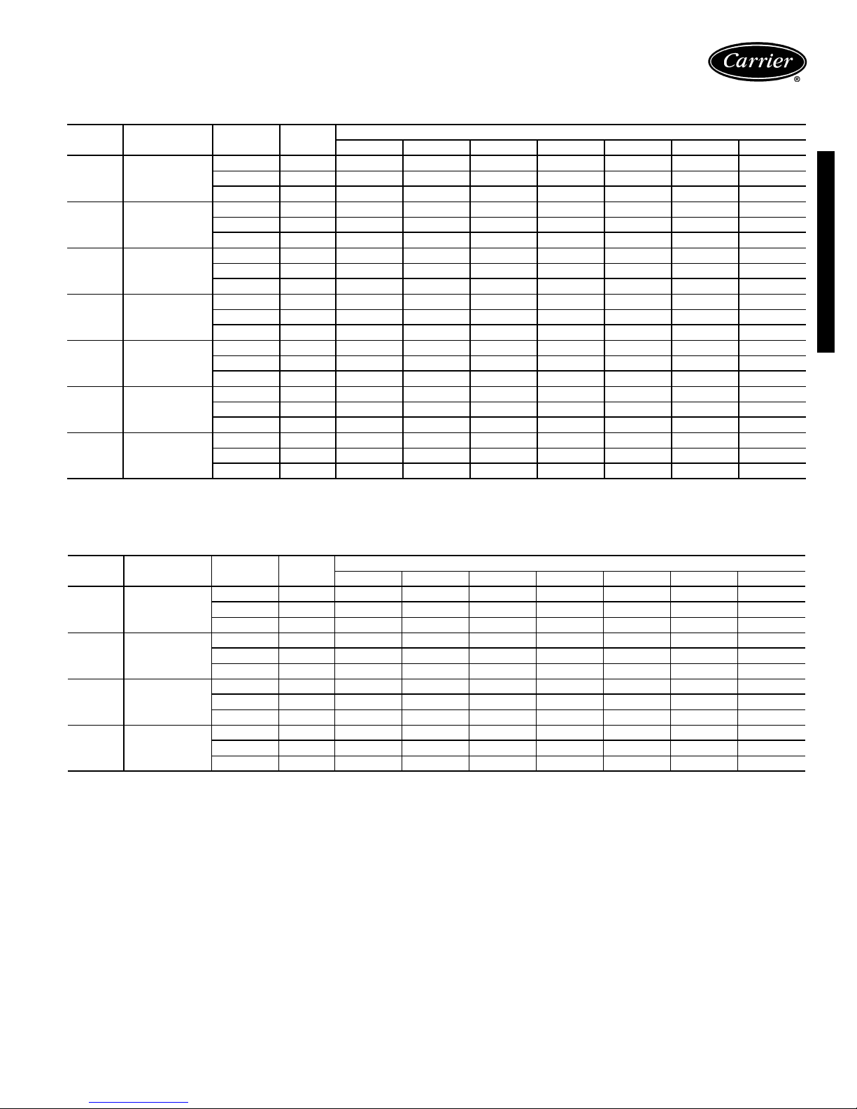
Sound data
42CA,CG,CE,CK SOUND RATINGS — OCTAVE BAND POWER LEVEL RATINGS* (dB)
SOUND POWER DATA
SIZE
02 200
03 300
04 400
06 600
08 800
10 1000
12 1200
*Testing per ARI Standard 350-86.
NOMINAL
CFM
High 1130 59 58 59 57 52 49 46
Medium 1060 54 54 55 51 42 42 41
Low 940 45 49 51 47 43 37 33
High 1125 61 59 61 58 54 51 47
Medium 1025 55 54 54 51 46 42 41
Low 925 43 48 49 46 42 36 31
High 1400 62 61 62 59 55 51 46
Medium 905 54 54 54 50 46 41 26
Low 725 49 48 47 42 34 — —
High 1525 63 62 63 60 56 53 48
Medium 1100 55 54 54 51 47 41 31
Low 690 51 50 49 44 36 — —
High 1500 66 66 67 64 60 58 53
Medium 1045 59 56 59 55 47 42 37
Low 675 51 51 50 46 38 — —
High 1365 73 70 71 68 64 62 58
Medium 785 62 60 61 57 51 48 46
Low 700 56 56 57 52 46 40 34
High 1540 78 75 76 73 68 67 63
Medium 1155 68 67 68 64 59 56 54
Low 740 59 60 60 56 50 43 37
SPEED RPM
CENTER FREQUENCY — Hz
125 250 500 1000 2000 4000 8000
42C,V Series Units
42CF SOUND RATINGS — OCTAVE BAND POWER LEVEL RATINGS* (dB)
SIZE NOMINAL CFM SPEED RPM
High108562656563585447
04 400
06 600
08 800
10 1000
*Testing per ARI Standard 350-86.
Medium98060626260565143
Low 840 57 59 59 56 51 46 37
High107562656563585447
Medium95560626260565143
Low 740 57 59 59 56 51 46 37
High104562656563585447
Medium86560626260565143
Low 715 57 59 59 56 51 46 37
High110062656563585447
Medium 1015 60 62 62 60 56 51 43
Low 900 57 59 59 56 51 46 37
CENTER FREQUENCY — Hz
125 250 500 1000 2000 4000 8000
29
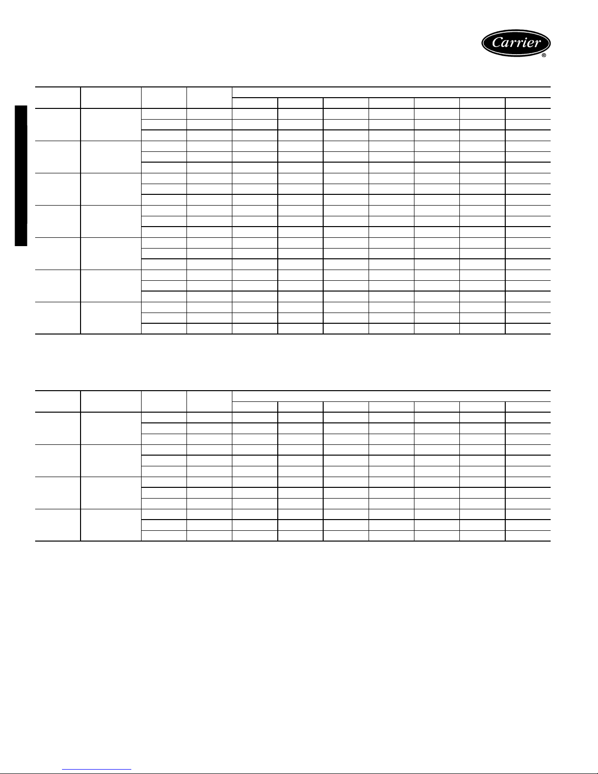
Sound data (cont)
42VA,VB,VF SOUND RATINGS — OCTAVE BAND SOUND POWER LEVEL RATINGS* (dB)
SOUND POWER DATA
SIZE
02 200
03 300
04 400
42C,V Series Units
06 600
08 800
10 1000
12 1200
*Testing per ARI Standard 350-86.
NOMINAL
CFM
SPEED RPM
High 1130 63 58 53 46 40 34 25
Medium 1090 58 57 51 45 39 32 —
Low 1025 61 57 50 44 37 30 —
High 1120 65 60 54 48 42 35 26
Medium 1070 60 59 53 47 41 34 —
Low 1000 63 59 52 46 39 32 —
High 1520 66 67 64 58 50 45 39
Medium 1085 58 60 53 47 40 32 —
Low 840 52 55 47 40 33 — —
High 1625 67 68 65 59 53 48 42
Medium 1310 61 62 56 52 46 40 —
Low 825 54 56 48 41 34 — —
High 1610 68 68 65 60 55 51 44
Medium 1300 63 64 59 54 50 45 36
Low 820 55 56 49 43 37 28 —
High 1530 68 69 65 61 54 49 44
Medium 1095 66 66 60 56 50 45 38
Low 850 58 58 52 46 38 31 —
High 1625 70 71 67 63 56 51 46
Medium 1310 69 69 63 59 53 48 42
Low 830 60 61 54 48 41 34 —
125 250 500 1000 2000 4000 8000
CENTER FREQUENCY — Hz
42VC,VE SOUND RATINGS — OCTAVE BAND SOUND POWER LEVEL RATINGS* (dB)
SIZE
02 400
03 600
04 800
06 1000
*Testing per ARI Standard 350-86.
NOMINAL
CFM
SPEED RPM
High 1325 60 63 60 56 53 50 47
Medium 890 53 53 51 46 43 38 32
Low 655 50 48 43 38 33 — —
High 1570 64 67 63 60 56 54 50
Medium 1205 56 58 53 50 47 43 37
Low 835 49 51 47 41 36 29 —
High 1520 65 68 64 61 57 55 51
Medium 1105 57 59 54 51 48 44 38
Low 765 50 52 48 42 37 30 —
High 1575 66 67 63 61 56 53 50
Medium 1205 58 58 55 53 48 43 37
Low 835 51 50 47 44 38 30 —
125 250 500 1000 2000 4000 8000
CENTER FREQUENCY — Hz
30
 Loading...