


42CA
Carrier 42CA, 42CE, 42CK, 42VA, 42CG Installation, Start-up And Service Instructions Manual
...
42C,D,V Series
Fan Coil Air Conditioners
Installation, Start-Up and Service
Instructions
CONTENTS
Page
SAFETY CONSIDERATIONS. . . . . . . . . . . . . . . . . . . . . . 1
INTRODUCTION. . . . . . . . . . . . . . . . . . . . . . . . . . . . . . . . .1,2
PHYSICAL DATA . . . . . . . . . . . . . . . . . . . . . . . . . . . . . . . 2, 3
PRE-INSTALLATION . . . . . . . . . . . . . . . . . . . . . . . . . . 4-32
Unpack and Inspect Units. . . . . . . . . . . . . . . . . . . . . . . . 4
Protect Units From Damage. . . . . . . . . . . . . . . . . . . . . . 4
Prepare Jobsite for Unit Installation. . . . . . . . . . . . . . 4
Identify and Prepare Units . . . . . . . . . . . . . . . . . . . . . . . 4
INSTALLATION . . . . . . . . . . . . . . . . . . . . . . . . . . . . . . 33-49
Step 1 — Place Units in Position . . . . . . . . . . . . . . . . 33
• 42C UNITS
• 42V UNITS
• 42D UNITS
Step 2 — Make Piping Connections . . . . . . . . . . . . . 34
• VALVE PACKAGES
• DRAIN CONNECTIONS
• WATER SUPPLY/RETURN CONNECTIONS
• STEAM CONNECTIONS
• DIRECT EXPANSION (DX) REFRIGERANT PIPING
• TEST AND INSULATE
Step 3 — Make Electrical Connections . . . . . . . . . . 46
• FACTORY-INSTALLED OPTIONS
• STANDARD WIRING PACKAGES
Step 4 — Make Duct Connections. . . . . . . . . . . . . . . 47
Step 5 — Frame and Finish Unit. . . . . . . . . . . . . . . . . 47
Step 6 — Cut Out Openings for Grilles and
Thermostats . . . . . . . . . . . . . . . . . . . . . . . . . . . . . . . . . . 47
Step 7 — Make Final Preparations . . . . . . . . . . . . . . 48
START-UP . . . . . . . . . . . . . . . . . . . . . . . . . . . . . . . . . . . 49, 50
Cooling/Heating System . . . . . . . . . . . . . . . . . . . . . . . . 49
Air System Balancing . . . . . . . . . . . . . . . . . . . . . . . . . . . 49
Water System Balancing . . . . . . . . . . . . . . . . . . . . . . . . 49
Water Treatment . . . . . . . . . . . . . . . . . . . . . . . . . . . . . . . . 49
Controls Operation. . . . . . . . . . . . . . . . . . . . . . . . . . . . . . 50
SERVICE . . . . . . . . . . . . . . . . . . . . . . . . . . . . . . . . . . . . . 50, 51
Excessive Condensation on Unit. . . . . . . . . . . . . . . . 50
To Clean Coil. . . . . . . . . . . . . . . . . . . . . . . . . . . . . . . . . . . . 50
Drain . . . . . . . . . . . . . . . . . . . . . . . . . . . . . . . . . . . . . . . . 50
Check Drain. . . . . . . . . . . . . . . . . . . . . . . . . . . . . . . . . . . . . 50
Fan Motor Bearings . . . . . . . . . . . . . . . . . . . . . . . . . . . . . 50
Clean Fan Wheel . . . . . . . . . . . . . . . . . . . . . . . . . . . . . . . . 50
Clean Electric Heater. . . . . . . . . . . . . . . . . . . . . . . . . . . . 50
Filters . . . . . . . . . . . . . . . . . . . . . . . . . . . . . . . . . . . . . . . . . . . 51
Clean or Replace Air Filters . . . . . . . . . . . . . . . . . . . . . 51
Electrical Wiring and Controls . . . . . . . . . . . . . . . . . . 51
Valves and Piping. . . . . . . . . . . . . . . . . . . . . . . . . . . . . . . 51
Warranty . . . . . . . . . . . . . . . . . . . . . . . . . . . . . . . . . . . . . . . . 51
Page
APPENDIX A — POTENTIOMETER
ADJUSTMENT. . . . . . . . . . . . . . . . . . . . . . . . . . . . . . . . . . . 52
APPENDIX B — EVO/ECM 4-SPEED
ADJUSTMENT. . . . . . . . . . . . . . . . . . . . . . . . . . . . . . . . . . . 53
APPENDIX C — 42CE/DC RETURN
MODIFICATION. . . . . . . . . . . . . . . . . . . . . . . . . . 54, 55
START-UP CHECKLIST FOR 42C,D,V SERIES
FAN COIL AIR CONDITIONERS . . . . . . . CL-1, CL-2
SAFETY CONSIDERATIONS
Installation of this unit can be hazardous due to electrical components and equipment location (such as a ceiling or elevated
structure). Only trained, qualified installers and service
mechanics should install and service this equipment.
When installing this unit, observe precautions in the literature,
labels attached to the equipment, and any other safety precautions that apply.
• Follow all safety codes.
• Wear safety glasses and work gloves. Never wear bulky
or loose fitting clothing when working on any mechanical equipment. Gloves should be worn for proper protection against heat and other possible injuries. Safety
glasses or goggles should always be worn when drilling,
cutting, or working with chemicals such as refrigerants
or lubricants.
• Use care in handling and installing this unit.
• Never pressurize any equipment beyond specified test
pressures. Always pressure test with an inert fluid or gas
such as clear water or dry nitrogen to avoid possible
damage or injury in the event of a leak or component
failure during testing. Always protect adjacent flammable material when welding or soldering. Use a suitable
heat-shield material to contain sparks or drops of solder.
Have a fire extinguisher readily available.
WARNING
ELECTRIC SHOCK HAZARD. To avoid the possibility
of electrical shock, open and tag all service switches before
installing this equipment.
INTRODUCTION
Carrier fan coil units represent a prudent investment offering trouble-free operation and long service with proper installation, operation, and regular maintenance. Your equipment is
initially protected under the manufacturer’s standard warranty;
however, this warranty is provided under the condition that the
steps outlined in this manual for initial inspection, proper installation, regular periodic maintenance, and everyday operation of the equipment be followed in detail. This manual should
be fully reviewed in advance before initial installation, start-up,
Manufacturer reserves the right to discontinue, or change at any time, specifications or designs without notice and without incurring obligations.
Catalog No. 04-53420011-01 Printed in U.S.A. Form 42-6SI Pg 1 11-17 Replaces: 42-5SI
and any maintenance. Should any questions arise, please
contact your local sales representative or the factory BEFORE
proceeding.
This document contains general installation instructions for
the 42C,D,V unit fan coils. Refer to the unit wiring diagram installed on the blower housing or specific manufacturer literature for any other type of factory-mounted controls.
See drawings for unit configurations, dimensions, clearances,
and pipe connections. Refer to unit wiring label for all electrical
connections; follow NEC (National Electrical Code) and local
codes.
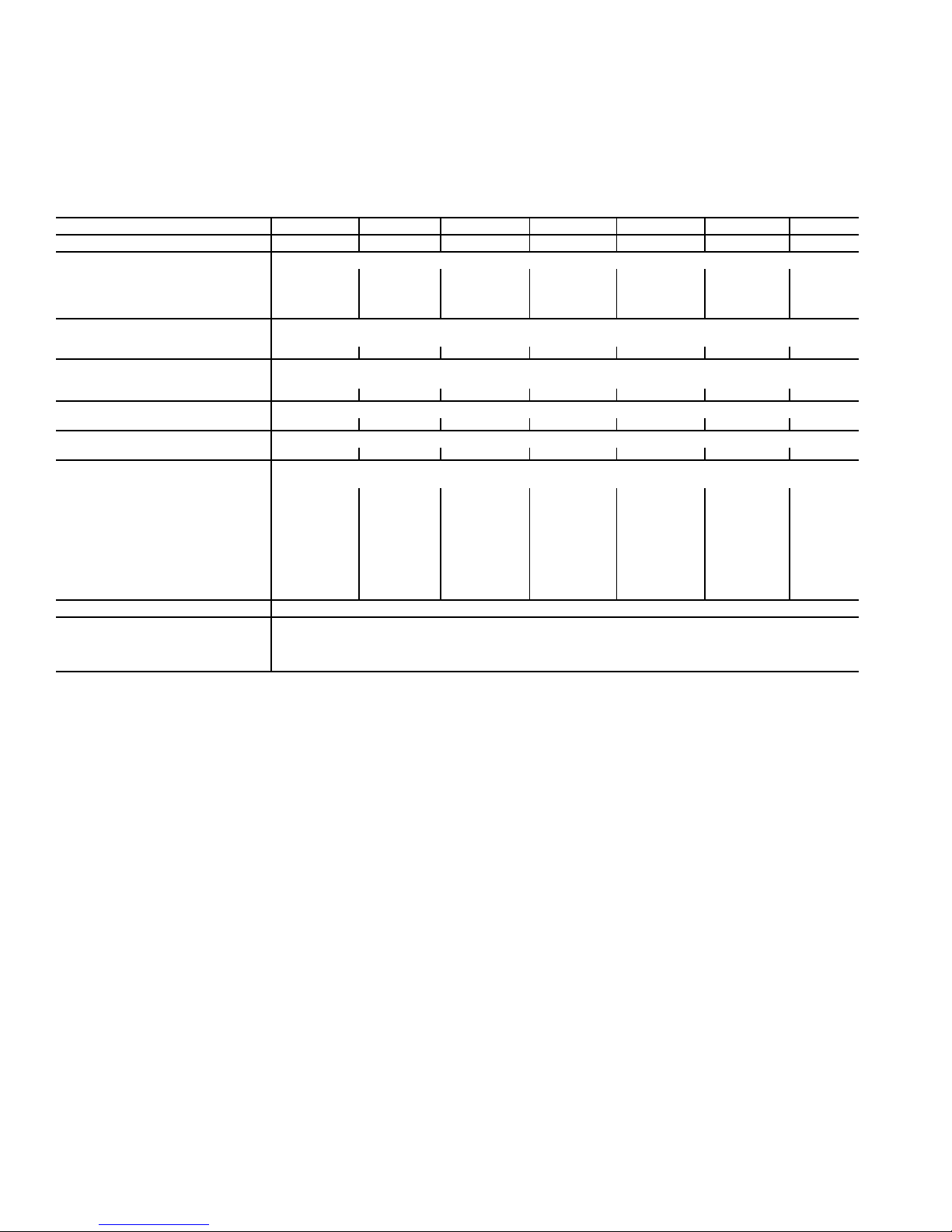
PHYSICAL DATA
Component weight data, shipping weights, and filter data of
the 42C,D,V units are provided in Tables 1-4.
Table 1 — Physical Data — 42C Series Units
UNIT SIZE 42C 02 03 04 06 08 10 12
NOMINAL AIRFLOW (cfm) 200 300 400 600 800 1000 1200
SHIPPING WEIGHT (lb)*
42CA 36 39 49 59 64 95 107
42CE 55 60 70 82 95 135 154
42CG 98 118 126 168 176 215 245
42CK 115 120 135 150 155 227 241
COIL WATER WEIGHT
(Approx lb per row of coil)
42CA, CE, CG, CK 0.7 0.8 1.0 1.4 1.7 2.3 2.7
COILS
FPI 10 fins/inch
Coil Face Area (sq ft) 0.8 1.1 1.4 1.9 2.3 3.2 3.7
MOTOR (qty)
42C Series 111 1 1 22
BLOWER (qty)
42CA, CE, CG, CK 112 2 2 44
FILTERS
Nominal Size (in.) (1-in. thick)
42CA NA NA NA NA NA NA NA
42CE† 10 x 18 10 x 22 10 x 28 10 x 33 10 x 40 10 x 54 10 x 62
42CG
Bottom Return 10 x 23
Rear Return 8 x 23
42CK
Bottom Return 10 x 28 10 x 28 10 x 33 10 x 45 10 x 45 10 x 62 10 x 62
Rear Return 7 x 21 7 x 21 7 x 27 7 x 38 7 x 38 7 x 52 7 x 52
Qty 111 1 1 11
SUPPLY DUCT COLLAR 1-in.
PIPING CONNECTIONS (Sweat) (in. OD)
Coil Outlet and Inlet
Drain Connection
Tell-Tale Drain
*Calculate Operating Weight of Unit: Shipping Weight + Coil Water
Weight x Number of Coil Rows.
1
/
2
1
/
2
10 x 28 10 x 321/
8 x 28 8 x 321/
2
2
10 x 37 10 x 41 10 x 541/
8 x 37 8 x 41 8 x 541/
5
/
8
7
/
8
5
/
8
10 x 63
2
8 x 63
2
†Filter size if located in return-air plenum.
2
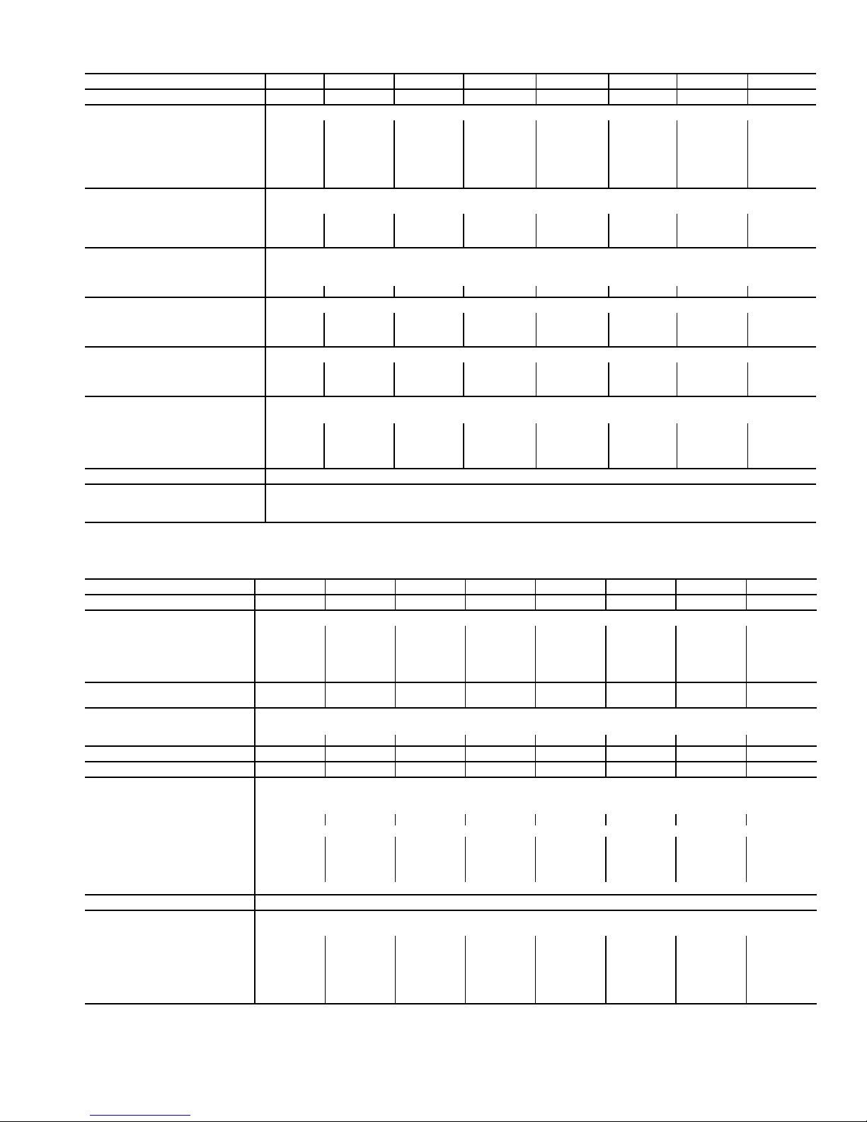
Table 2 — Physical Data — 42V Series Units
UNIT SIZE 42V 01 02 03 04 06 08 10 12
NOMINAL AIRFLOW (cfm) 150 200 300 400 600 800 1000 1200
SHIPPING WEIGHT (lb)*
42VA — 42 47 57 77 79 108 127
42VB — 63 68 82 99 101 133 154
42VC — 50 60 72 110 — — —
42VE — 72 100 108 154 — — —
42VF — 64 69 83 100 102 135 156
42VG 40 — 74 — — — — —
COIL WATER WEIGHT
(Approx lb per row of coil)
42VA, VB, VC†, VF — 0.7 0.8 1.0 1.4 1.7 2.3 2.7
42VE — 0.9 1.2 1.6 2.3 — — —
42VG 0.4 — 1.0 — — — — —
COILS
FPI (42VA, VB, VF) 12 fins/inch
FPI (42VC, VE, VG) 10 fins/inch
Coil Face Area (sq ft) 0.8 0.8 1.1 1.4 1.9 2.3 3.2 3.7
MOTOR (qty)
42VA, VB, VF —111 1122
42VC, VE —1 1 1 2 — — —
42VG 1— 2 — — — — —
BLOWER (qty)
42VA, VB, VF —112 2244
42VC, VE —2 2 2 4 — — —
42VG 1— 2 — — — — —
FILTERS
Nominal Size (in.) (1-in. thick)
42VA, VB, VF —7
42VC, VE —7 x 21
42VG 10 x 14
Qty 1111 1111
3
/4 x 213/473/4 x 213/473/4 x 313/473/4 x 413/473/4 x 433/473/4 x 573/473/4 x 653/
3
/
7 x 263/
1
/
2
4
— 10 x 28 — — — — —
7 x 343/
4
7 x 483/
4
4
———
4
SUPPLY DUCT COLLAR 1-in.
PIPING CONNECTIONS (Sweat) (in.)
Coil Outlet and Inlet
Drain Connection
*Calculate Operating Weight of Unit: Shipping Weight + Coil Water Weight x
Number Of Coil Rows.
†Available in sizes 02-06.
5
/8 OD
3
/4 MPT
Table 3 — Physical Data — 42D Series Units
UNIT SIZE 42D 0608101214161820
NOMINAL AIRFLOW (cfm) 600 800 1000 1200 1400 1600 1800 2000
SHIPPING WEIGHT (lb)*
42DA 64 79 90 108 119 124 141 151
42DC 94 107 150 169 174 178 195 220
42DD 135 145 155 180 190 200 215 230
42DE 150 160 170 195 205 215 230 235
42DF 157 167 177 202 215 225 240 255
COIL WATER WEIGHT
(Approx lb per row of coil)
COILS
FPI 10 fins/inch
Coil Face Area (sq ft) 1.62.12.53.03.54.14.65.0
MOTOR (qty) 11122222
BLOWER (qty) 11122222
FILTERS
Nominal Size (in.) (1-in. thick)
42DA NA
42DC 14 x 21 14 x 26 14 x 30 14 x 35 14 x 40 14 x 45 14 x 50 14 x 54
42DD
(Front Return) 12
(Bottom Return) 12
42DE 14 x 14
42DF 14 x 14 14 x 20 14 x 24 14 x 28 14 x 34 14 x 38 14 x 44 14 x 48
Qty
SUPPLY DUCT COLLAR 1-in.
PIPING CONNECTIONS
Coil Inlet/Outlet (in. OD)
1 and 2 Row
3 Row
4 Row
5 Row
6 Row
8 Row 11/
1.31.61.92.32.73.03.43.7
3
/4 x 21 123/4 x 26 123/4 x 30 123/4 x 35 123/4 x 40 123/4 x 45 123/4 x 50 123/4 x 54
3
/4 x 20 123/4 x 25 123/4 x 29 123/4 x 34 123/4 x 39 123/4 x 44 123/4 x 49 123/4 x 53
3
/
14 x 193/
4
14 x 233/
4
14 x 283/
4
14 x 333/
4
14 x 383/
4
14 x 433/
4
14 x 473/
4
4
1
11/
5
/
8
5
/
8
7
/
8
7
/
8
7
/
8
8
5
/
8
5
/
8
7
/
8
7
/
8
7
/
8
8
11/
5
/
8
7
/
8
7
/
8
7
/
8
7
/
8
8
5
/
8
7
/
8
7
/
8
7
/
8
7
/
8
11/
8
11/
11/
15/
5
/
8
7
/
8
7
/
8
8
8
8
11/
11/
11/
15/
5
/
8
7
/
8
8
8
8
8
11/
11/
11/
15/
5
/
8
7
/
8
8
8
8
8
11/
11/
11/
15/
5
/
8
7
/
8
8
8
8
8
*Calculate Operating Weight of Unit: Shipping Weight + Coil Water Weight x Number of Coil Rows.
3

PRE-INSTALLATION
Unpack and Inspect Units —
inspected at the factory throughout the manufacturing process
under a strict detailed quality assurance program, and, where
possible, ALL major components and sub-assemblies are carefully tested for proper operation and verified for full compliance with factory standards. Operational testing of some customer-furnished components such as electronic control valves
and digital controllers may be a possible exception.
Each unit is carefully packaged for shipment to avoid damage during normal transit and handling. Equipment should always be stored in a dry place, and in the proper orientation as
marked on the carton. All shipments are made F.O.B. factory
and are the responsibility of the receiving party to inspect the
equipment upon arrival. Any obvious damage to the carton
and/or its contents should be recorded on the bill of lading and
a claim should be filed with the transportation company, and
Carrier should be advised. After determining the condition of
the carton exterior, carefully remove each unit from the carton
and inspect for hidden damage. At this time, check to make
sure that “furnished only” items such as thermostats, grilles etc.
are accounted for whether packaged separately or shipped at a
later date. Any hidden damage should be recorded and immediately reported to the transportation company, a claim should
be filed with the transportation company, and Carrier should be
notified. In the event a claim for shipping damage is filed, the
unit, shipping carton, and all packing must be retained for
physical inspection by the transportation company. All equipment should be stored in the factory shipping carton with internal packing in place until installation.
At the time of receipt, the equipment type and arrangement
should be verified against the order documents. Should any
discrepancy be found, the local sales representative should be
notified immediately so that proper action may be taken.
Should any questions arise concerning warranty repairs, the
factory must be notified BEFORE any corrective action is taken. Where local repairs or alterations can be accomplished, the
factory must be fully informed of the extent and expected cost
of those repairs before work is begun. Where factory operations are required, the factory must be contacted for authorization to return equipment and a Return Authorization Number
will be issued. Unauthorized return shipments of equipment
and shipments not marked with an authorization number will
be refused. In addition, any claims for unauthorized expenses
will not be accepted by the manufacturer.
All units are carefully
Protect Units from Damage — All equipment is de-
signed and fabricated with robust materials and presents a
rugged appearance. Still, great care must be taken to assure
that no force or pressure is applied to the coil, piping, or drain
stub-outs during handling. Depending on the options and accessories, some units may contain delicate components that
may be damaged by improper handling. All units shall be handled by the chassis or as close as possible to the unit mounting
point locations. In the case of a full cabinet unit, the unit must
be handled by the exterior casing. This is acceptable provided
the unit is maintained in an upright position, and no force is applied that may damage internal components or painted
surfaces.
The equipment must always be properly supported. Temporary supports used during installation or service must be adequate to hold the equipment securely. Equipment should always be stored in the proper orientation as marked on the carton. To maintain warranty, protect units against hostile
environment (such as rain, snow, or extreme temperatures),
theft, vandalism, and debris on jobsite. Equipment covered in
this manual is not suitable for outdoor installations. Do not allow foreign material to fall into drain pan. Prevent dust and debris from being deposited on motor, fan wheels and cooling/
heating coils. Failure to do so may have serious adverse effects
on unit operation, and in the case of the motor and blower assembly, may result in immediate or premature failure. Manufacturer's warranty is void if foreign material is allowed to be
deposited on the motor or blower wheels of any unit. Some
units and/or job conditions may require some form of temporary covering during construction.
Prepare Jobsite for Unit Installation — To save
time and to reduce the possibility of costly errors, set up a complete sample installation in a typical room at jobsite. Check all
critical dimensions such as pipe, wire, and duct connection
requirements. Refer to job drawings and product dimension
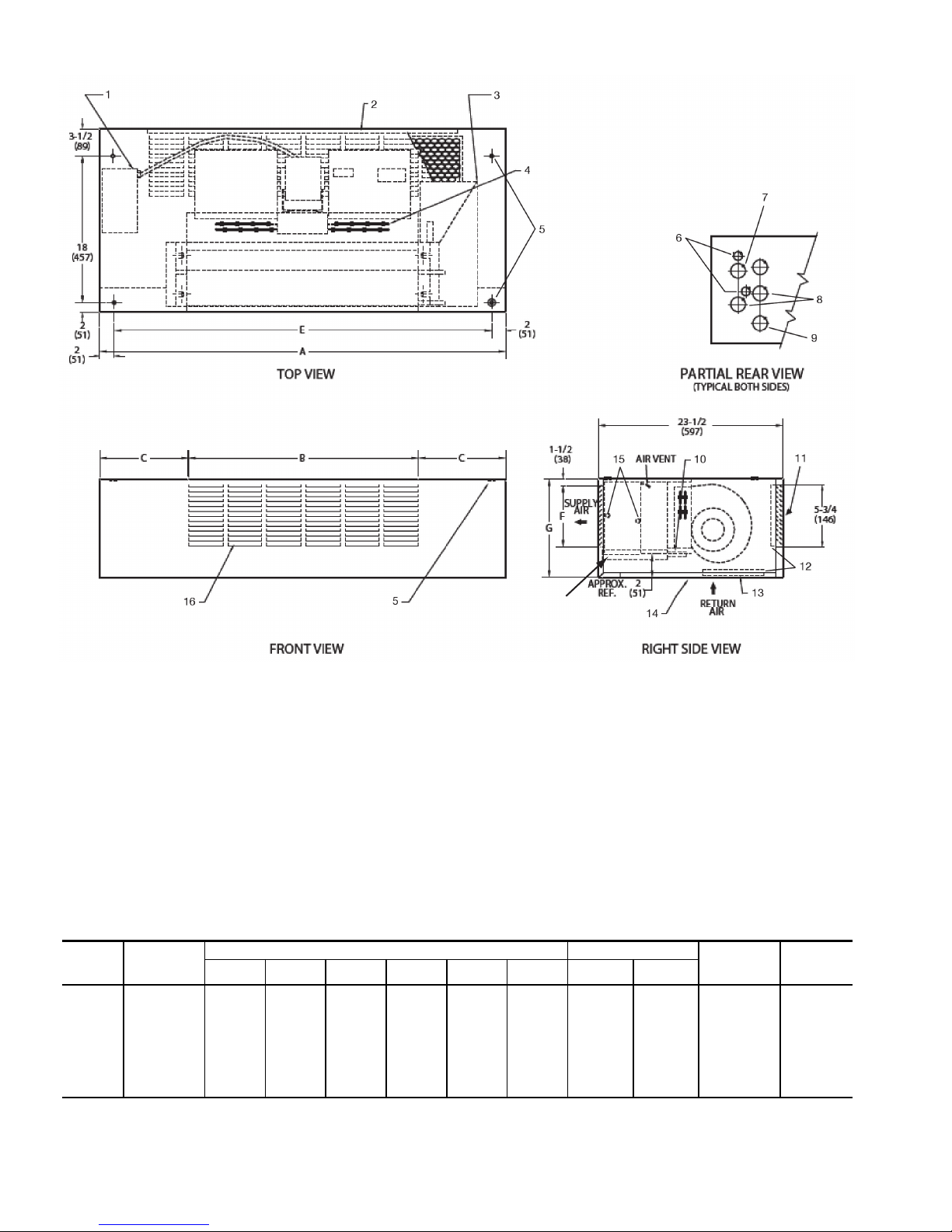
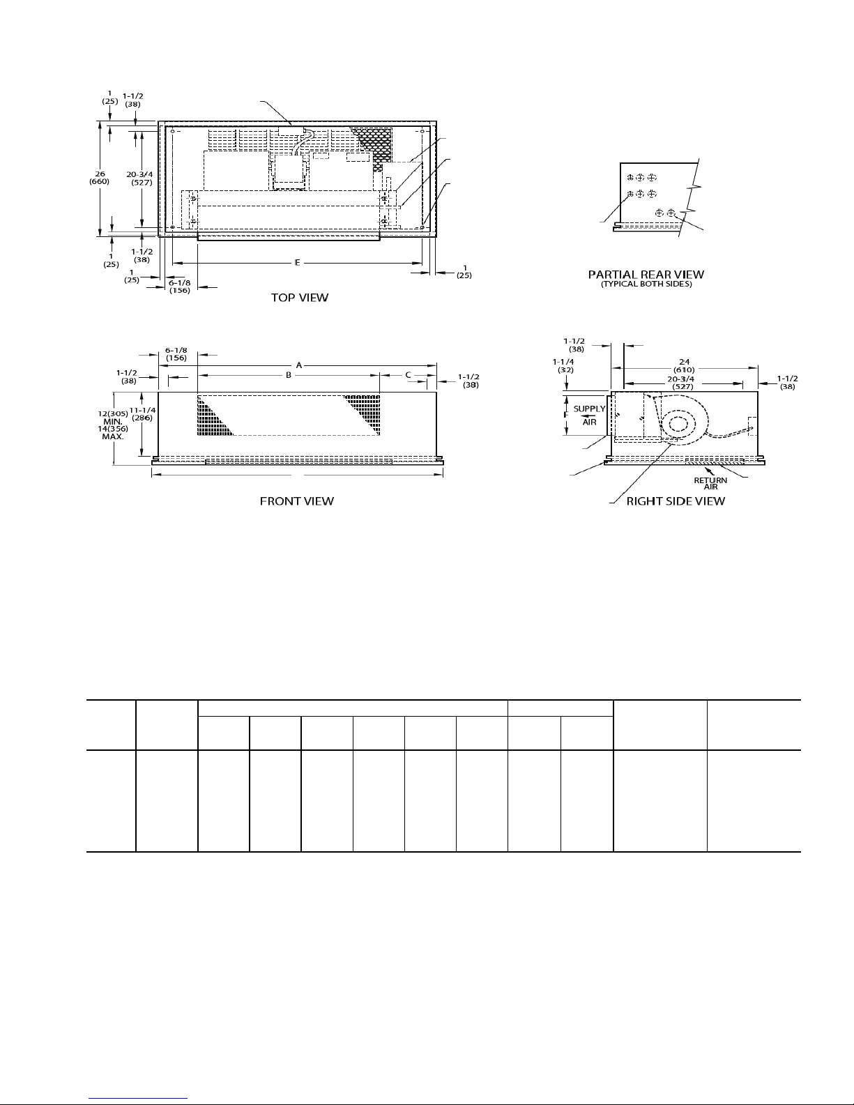
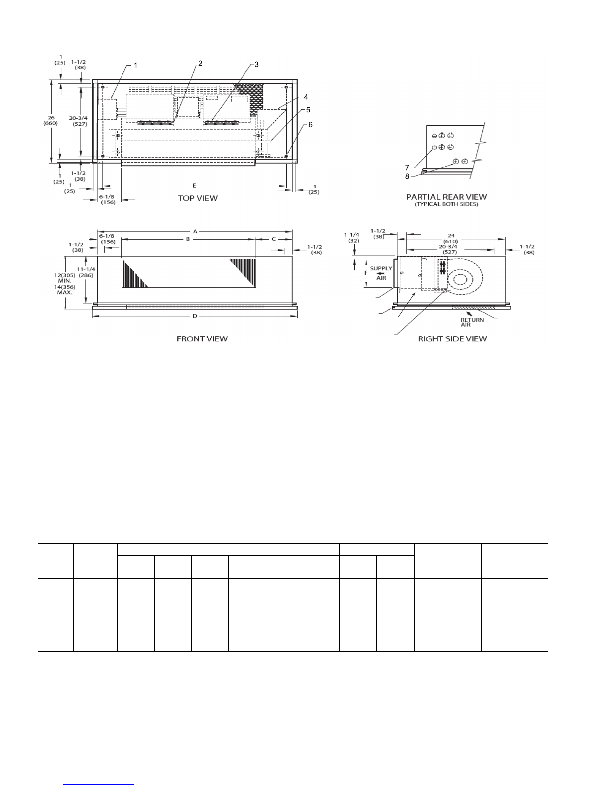
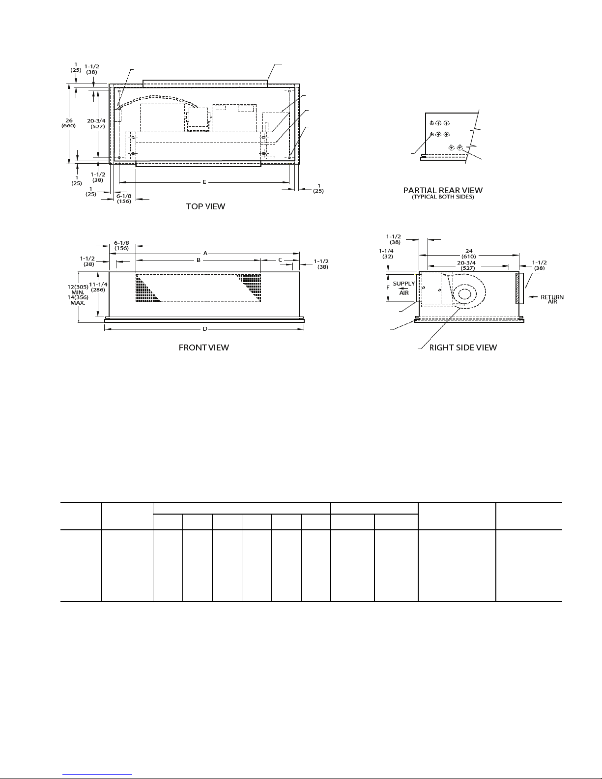
drawings as required (see Fig. 1-28). Instruct all trades in their
part of the installation.
Identify and Prepare Units — Be sure power require-
ments match available power source. Refer to unit nameplate
and wiring diagram.
1. Check all tags on unit to determine if shipping screws are
to be removed. Remove screws as directed.
2. Rotate the fan wheel by hand to ensure that the fan is
unrestricted and can rotate freely. Check for shipping
damage and fan obstructions. Adjust blower motor as
required.
3. Perform "Dry Fit" of valve assembly that may be shipped
unattached to unit coil assembly. Should any questions
arise on fit up please contact your local representative.
4. Horizontal plenum type 42CE units may be shipped with
a bottom return-air inlet. These units may be converted to
rear return as outlined in Appendix C.
5. Hi-Performance plenum-type 42DC units may be
shipped with a bottom return-air inlet. These units may
be converted to rear return as outlined in Appendix C.
4
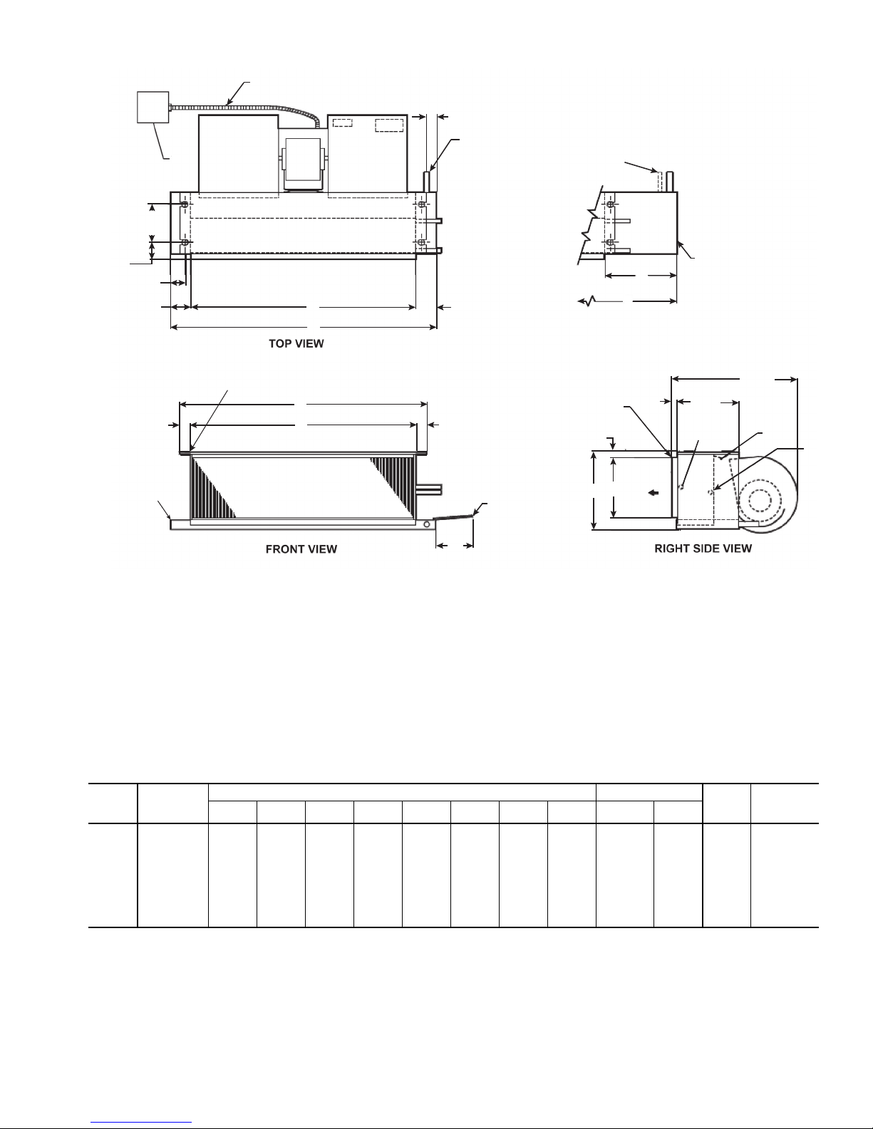
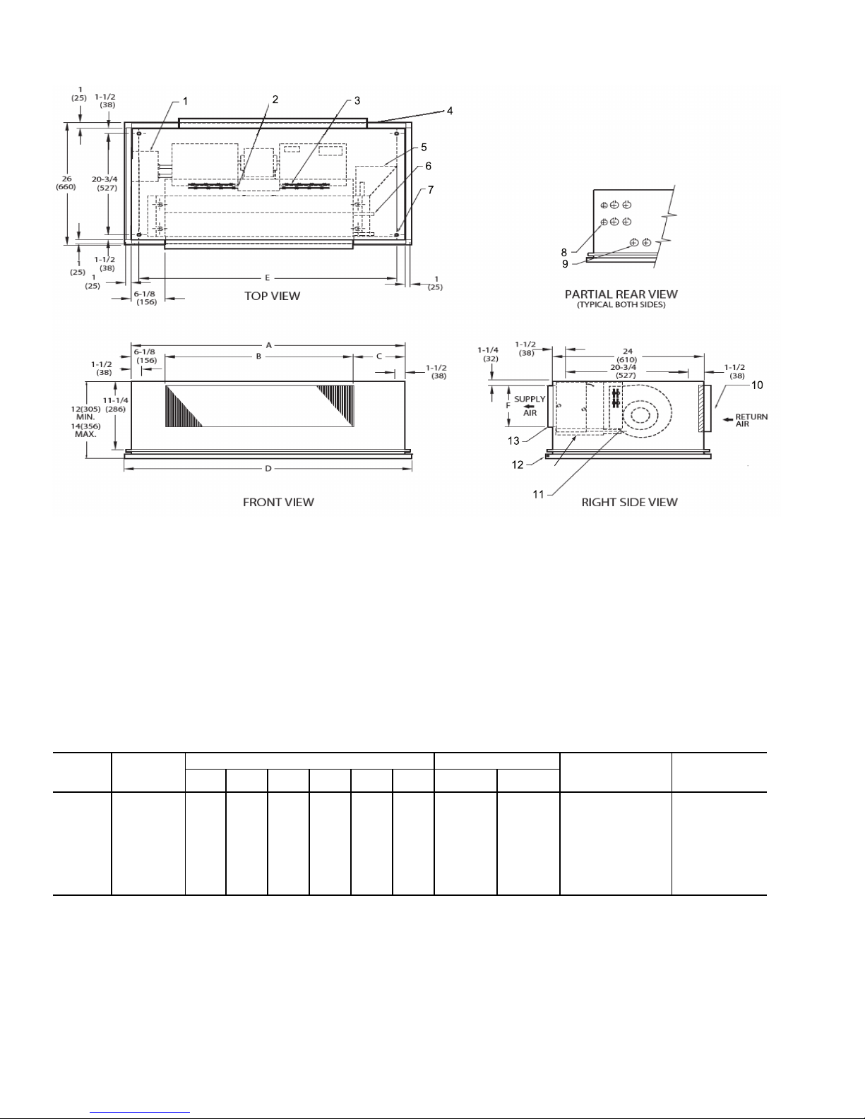
1
2
3
1
(25)
3
(76)
B
A
2-1/4
(64)
1-1/8
(29)
6
(152)
1-1/2
(38)
D’
A’
5
4
E
MTG. HOLES
H
6
3/4
(19)
3/4
(19)
11
5
16
(406)
SUPPLY
AIR
F
G
7/8
(22)
7
10
8
9
17-1/2
(445)
8-3/8
(213)
1
(25)
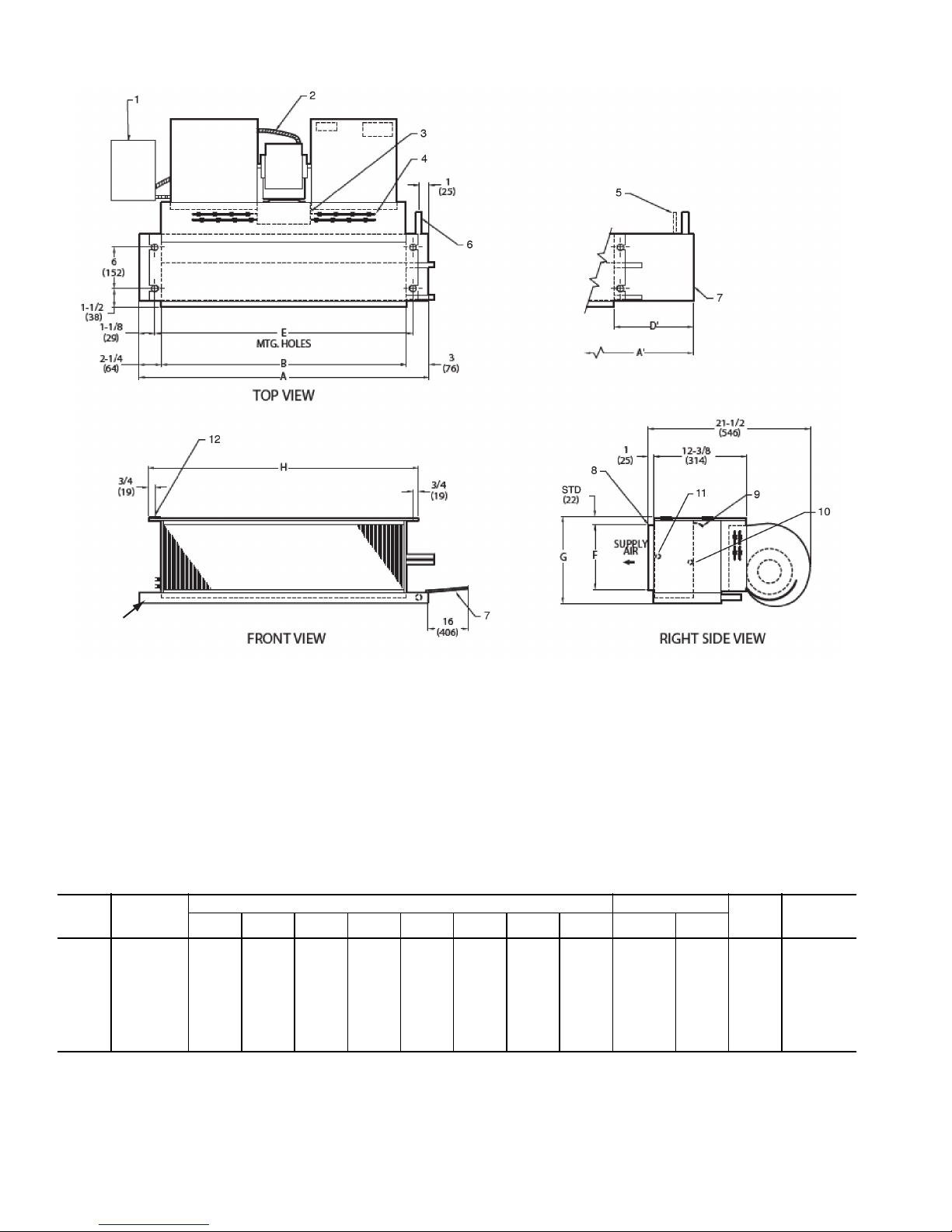
LEGEND
1—Junction Box (remote mount)
2—Flexible Metal Conduit
3—Drain Conn,
7
/8-in. OD
4 — Tell-Tale Drain Conn, 5/8-in. OD (optional)
5—Drip Lip (optional, shipped loose)
6—Hanger Slots (4), Rubber Grommet
has
3
/8-in. Diameter Hole
7—Supply Duct Collar, 1-in.
8—Air Vent,
1
/8-in. MPT
9—Return Conn,
5
/8-in. OD
10 — Supply Conn,
5
/8-in. OD
11 — Drain Pan
*Unit weights are based on dry coils and minimum rows. Weights exclude packaging, valves, and other components.
UNIT
SIZE
NOM
AIRFLOW
(Cfm)
DIMENSIONS (in.) QTY/UNIT FACE
AREA
(sq ft)
UNIT
WEIGHT*
(lb)
AA’BD’E F G H
Blower Motor
02 200 21
1
/4311/
4
16 13 181/
4
61/
4
83/
4
193/
4
1 1 0.83 36
03 300 25
1
/4361/
4
20 14 221/
4
61/
4
83/
4
233/
4
1 1 1.08 39
04 400 31
1
/4431/
4
26 15 281/
4
61/
4
83/
4
293/
4
2 1 1.35 49
06 600 36
1
/4431/
4
31 10 331/
4
71/
2
10 343/
4
2 1 1.88 59
08 800 43
1
/4571/
4
38 17 401/
4
71/
2
10 413/
4
2 1 2.31 64
10 1000 57
1
/4651/
4
52 11 541/
4
71/
2
10 553/
4
4 2 3.16 95
12 1200 65
1
/4751/
4
60 13 621/
4
71/
2
10 633/
4
4 2 3.65 107
NOTES:
1. Right hand unit shown; left hand unit opposite. Coil connection
locations are ±5/8-inch.
2. Unit sizes 02 and 03 have one motor, one blower; sizes 04
through 08 have one motor, 2 blowers; sizes 10 and 12 have
2 motors, 4 blowers.
3. Standard 3-row coil shown.
4. Overall unit dimension increases by 4 in. with optional electric
heat.
5. Not shown: 3-speed fan switch; wall plate; closed cell foam on
main drain pan.
6. Units have galvanized finish.
7. For optional coil connections, view 42CA-203-1 using the Fan Coil
Builder.
8. Dimensions shown in inches (mm).
a42-4099.eps
Fig. 1 — 42CA Furred-In Horizontal Unit Dimensions
5
13
LEGEND
1—Junction Box (remote mount)
2—Flexible Metal Conduit
3 — Strip Heater High Limit
4 — Electric Strip Heater Element
5 — Tell-Tale Drain Conn,
5
/8-in. OD (optional)
6—Drain Conn, 7/8-in. OD
7—Drip Lip (optional, shipped loose)
8—Supply Duct Collar, 1-in.
9—Air Vent,
1
/8-in. MPT
10 — Return Conn, 5/8-in. OD
11 — Supply Conn,
5
/8-in. OD
12 — Hanger Slots (4), Rubber Grommet
has
3
/8-in. Diameter Hole
13 — Drain Pan
NOTES:
1. Right hand unit shown; left hand unit opposite. Coil connection
locations are ±
5
/8-inch.
2. Unit sizes 02 and 03 have one motor, one blower; sizes 04
through 08 have one motor, 2 blowers; sizes 10 and 12 have
2 motors, 4 blowers.
3. Standard 3-row coil shown.
4. Overall unit dimension increases by 4 in. with optional electric
heat.
5. Not shown: 3-speed fan switch; wall plate; closed cell foam on
main drain pan.
6. Units have galvanized finish.
7. For optional coil connections, view 42CA-203-1 using the Fan Coil
Builder.
8. Dimensions shown in inches (mm).
*Unit weights are based on dry coils and minimum rows. Weights exclude packaging, valves, and other components.
UNIT
SIZE
NOM
AIRFLOW
(Cfm)
DIMENSIONS (in.) QTY/UNIT FACE
AREA
(sq ft)
UNIT
WEIGHT*
(lb)
AA’BD’E F G H
Blower Motor
02 200 21
1
/4311/
4
16 13 181/
4
61/
4
83/
4
193/
4
1 1 0.83 38
03 300 25
1
/4361/
4
20 14 221/
4
61/
4
83/
4
233/
4
1 1 1.08 41
04 400 31
1
/4431/
4
26 15 281/
4
61/
4
83/
4
293/
4
2 1 1.35 51
06 600 36
1
/4431/
4
31 10 331/
4
71/
2
10 343/
4
2 1 1.88 61
08 800 43
1
/4571/
4
38 17 401/
4
71/
2
10 413/
4
2 1 2.31 66
10 1000 57
1
/4651/
4
52 11 541/
4
71/
2
10 553/
4
4 2 3.16 97
12 1200 65
1
/4751/
4
60 13 621/
4
71/
2
10 633/
4
4 2 3.65 109
a42-4100.eps
Fig. 2 — 42CA Furred-In Horizontal Unit with Electric Heat Dimensions
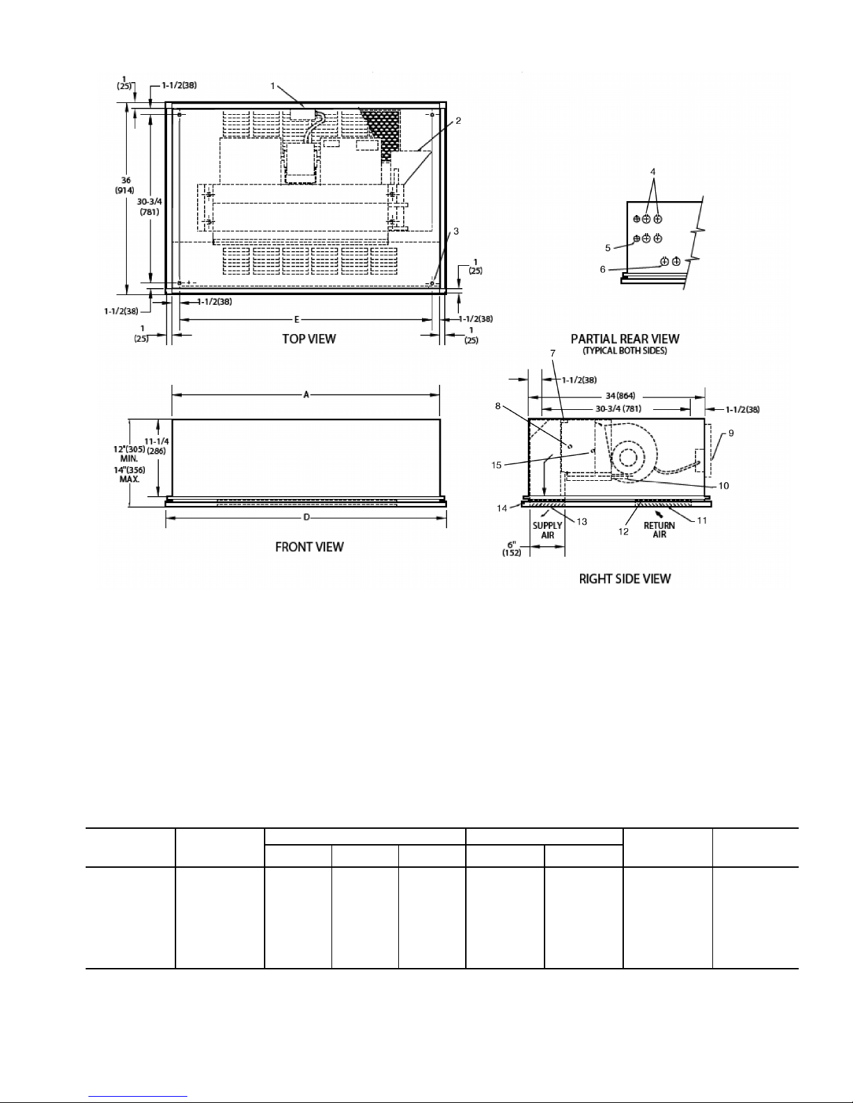
6
16
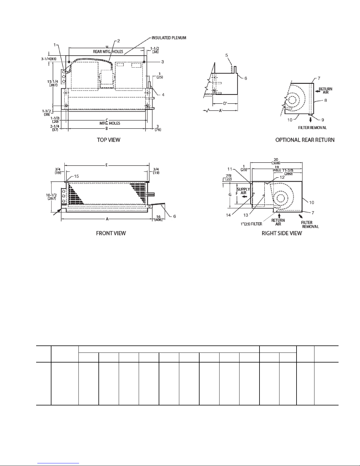
NOTES:
1. Right hand unit with standard 3-row coil shown; left hand unit opposite. Coil
connection locations are ±
5
/8-inch.
2. Unit sizes 02 and 03 have one motor, one blower; sizes 04 through 08 have
one motor, 2 blowers; sizes 10 and 12 have 2 motors, 4 blowers.
3. Standard 3-row coil shown.
4. Unit available with bottom or rear return air.
5. Overall dimension increases by 4 in. with optional electric heat.
6. Not shown: 3-speed fan switch; wall plate;
1
/2-in. fiberglass insulation on
inside of plenum, closed cell foam on main drain pan.
7. Units have galvanized finish.
8. For optional coil connections, view 42CA-203-1 using the Fan Coil Builder.
9. Dimensions shown in inches (mm).
LEGEND
1— Junction Box, 4 in. x 4 in.
2— Flexible Metal Conduit
3— Mounting Bracket
4— Drain Conn,
7
/8-in. OD
5— Tell-Tale Drain Conn,
5
/8-in. OD (optional)
6— Drip Lip (optional, shipped loose)
7— Filter
8— Return Duct Collar, 1-in.
9— Filter Access Panel
10 — Access Panel
11 — Supply Duct Collar, 1-in.
12 — Air Vent,
1
/8-in. MPT
13 — Return Conn,
5
/8-in. OD
14 — Supply Conn, 5/8-in. OD
15 — Hanger Slots (4), Rubber Grommet has
3
/8-in. Diameter Hole
16 — Drain Pan
*Unit weights are based on dry coils and minimum rows. Weights exclude packaging, valves, and other components.
UNIT
SIZE
NOM
AIRFLOW
(Cfm)
DIMENSIONS (in.) QTY/UNIT FACE
AREA
(sq ft)
UNIT
WEIGHT*
(lb)
AA’BCD’E F G H
Blower Motor
02 200 21
1
/4311/
4
16 181/
4
13 193/
4
61/
4
83/
4
153/
8
1 1 0.83 55
03 300 25
1
/4361/
4
20 221/
4
14 233/
4
61/
4
83/
4
193/
8
1 1 1.08 60
04 400 31
1
/4431/
4
26 281/
4
15 293/
4
61/
4
83/
4
253/
8
2 1 1.35 70
06 600 36
1
/4431/
4
31 331/
4
10 343/
4
71/
2
10 303/
8
2 1 1.88 82
08 800 43
1
/4571/
4
38 401/
4
17 413/
4
71/
2
10 373/
8
2 1 2.31 95
10 1000 57
1
/4651/
4
52 541/
4
11 553/
4
71/
2
10 513/
8
4 2 3.16 135
12 1200 65
1
/4751/
4
60 621/
4
13 633/
4
71/
2
10 593/
8
4 2 3.65 154
a42-4101
Fig. 3 — 42CE Furred-In Horizontal Unit with Plenum Dimensions
7
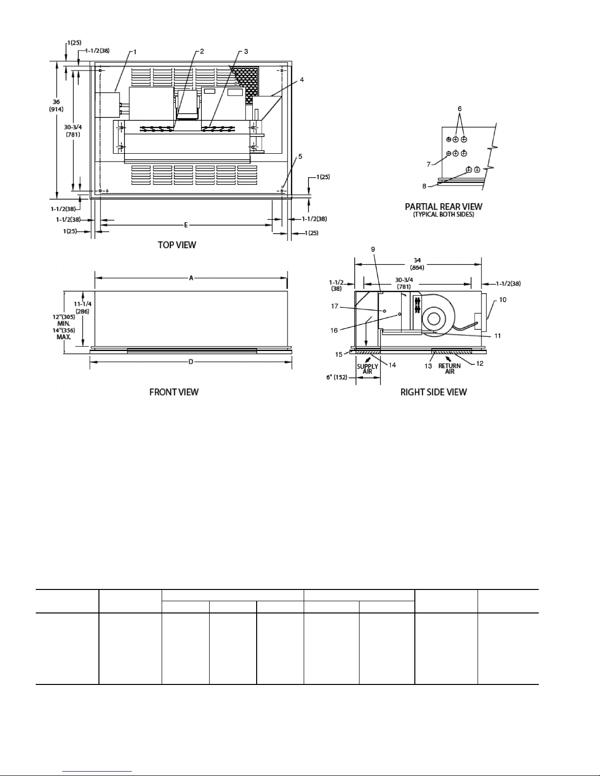
18
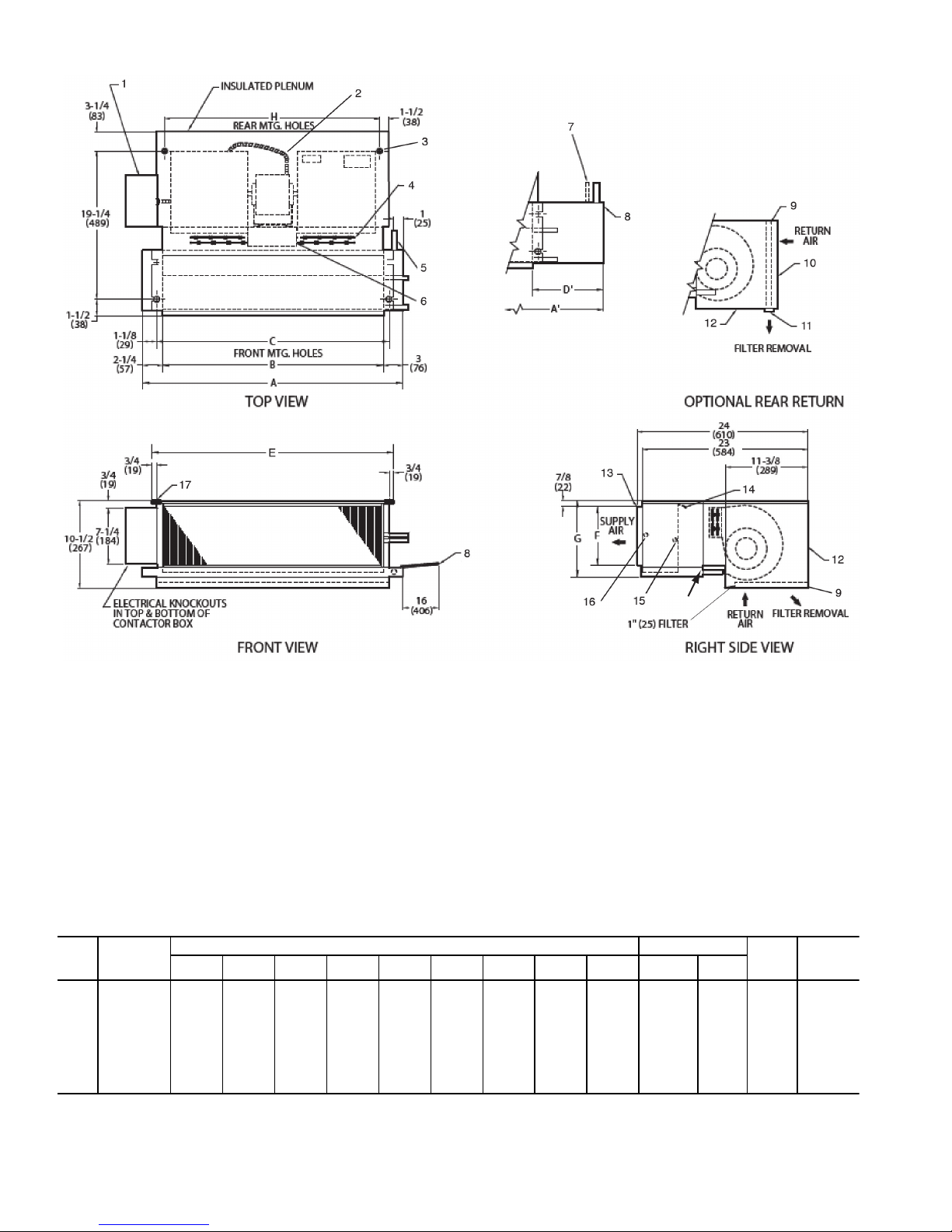
NOTES:
1. Right hand unit with standard 3-row coil shown; left hand unit opposite. Coil
connection locations are ±
5
/8-inch.
2. Unit sizes 02 and 03 have one motor, one blower; sizes 04 through 08 have
one motor, 2 blowers; sizes 10 and 12 have 2 motors, 4 blowers.
3. Standard 3-row coil shown.
4. Unit available with bottom or rear return air.
5. Overall dimension increases by 4 in. with optional electric heat.
6. Not shown: 3-speed fan switch; wall plate;
1
/2-in. fiberglass insulation on
inside of plenum, closed cell foam on main drain pan.
7. Units have galvanized finish.
8. For optional coil connections, view 42CA-203-1 using the Fan Coil Builder.
9. Dimensions shown in inches (mm).
LEGEND
1— Junction Box, 4 in. x 4 in.
2— Flexible Metal Conduit
3— Mounting Bracket
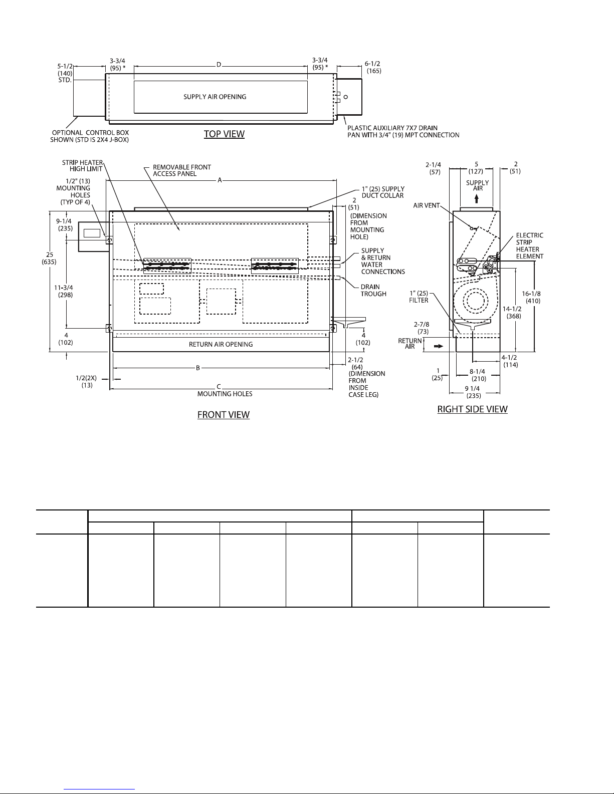
4— Electric Strip Heater Element
5— Drain Conn,
7
/8-in. OD
6— Strip Heater High Limit
7— Tell-Tale Drain Conn,
5
/8-in. OD (optional)
8— Drip Lip (optional, shipped loose)
9— Filter
10 — Return Duct Collar, 1-in.
11 — Filter Access Panel
12 — Access Panel
13 — Supply Duct Collar, 1-in.
14 — Air Vent,
1
/8-in. MPT
15 — Return Conn, 5/8-in. OD
16 — Supply Conn,
5
/8-in. OD
17 — Hanger Slots (4), Rubber Grommet has
3
/8-in. Diameter Hole
18 — Drain Pan
*Unit weights are based on dry coils and minimum rows. Weights exclude packaging, valves, and other components.
UNIT
SIZE
NOM
AIRFLOW
(Cfm)
DIMENSIONS (in.) QTY/UNIT FACE
AREA
(sq ft)
UNIT
WEIGHT*
(lb)
AA’B CD’E F G H
Blower Motor
02 200 21
1
/4311/
4
16 181/
4
13 193/
4
61/
4
83/
4
153/
8
1 1 0.83 57
03 300 25
1
/4361/
4
20 221/
4
14 233/
4
61/
4
83/
4
193/
8
1 1 1.08 62
04 400 31
1
/4431/
4
26 281/
4
15 293/
4
61/
4
83/
4
253/
8
2 1 1.35 72
06 600 36
1
/4431/
4
31 331/
4
10 343/
4
71/
2
10 303/
8
2 1 1.88 84
08 800 43
1
/4571/
4
38 401/
4
17 413/
4
71/
2
10 373/
8
2 1 2.31 97
10 1000 57
1
/4651/
4
52 541/
4
11 553/
4
71/
2
10 513/
8
4 2 3.16 137
12 1200 65
1
/4751/
4
60 621/
4
13 633/
4
71/
2
10 593/
8
4 2 3.65 156
A42-4102
Fig. 4 — 42CE Furred-In Horizontal Unit with Plenum and Electric Heat Dimensions
8
16
LEGEND
1— Junction Box, 4 in. x 4 in.
2— Optional Return Air Location
3— Drip Lip (optional, shipped loose)
4— Mounting Holes (4), Rubber Grommets
have
3
/8-in. Diameter Hole
5— Electrical Knockout,
7
/8-in. Diameter
6— Return Knockout, 1-in. Diameter
7— Supply Knockout, 11/2-in. Diameter
8— Drain Knockout, 1
1
/2-in. Diameter
9— Supply, Return Connections,
5
/8-in. OD
10 — Drain Connection,
7
/8-in. OD
11 — Optional Valve Package (inside cabinet)
12 — Filter
13 — Standard Stamped-Return Air Grille
14 — Removable Hinged Access Panel
15 — Supply Grille, Stamped, Standard
16 — Drain Pan
*Unit weights are based on dry coils and minimum rows. Weights exclude packaging, valves, and other components.
UNIT
SIZE
NOM
AIRFLOW
(Cfm)
DIMENSIONS (in.) QTY/UNIT FACE
AREA
(sq ft)
UNIT
WEIGHT*
(lb)
ABCEFG
Blower Motor
02 200 38 17
1
/
8
107/
16
34 53/
4
11 1 1 0.83 98
03 300 42 21
1
/
2
101/
4
38 53/
4
11 1 1 1.08 118
04 400 48 25
7
/
8
111/
16
44 53/
4
11 2 1 1.35 126
06 600 53 34
5
/
8
93/
16
49 63/
4
12 2 1 1.88 168
08 800 60 39 10
1
/
2
56 63/
4
12 2 1 2.31 176
10 1000 74 52
1
/
8
1015/
16
70 63/
4
12 4 2 3.16 215
12 1200 82 60
7
/
8
109/
16
78 63/
4
12 4 2 3.65 245
NOTES:
1. Right hand unit shown; left hand unit opposite. Coil connection locations
are ±
5
/8-inch.
2. Unit sizes 02 and 03 have one motor, one blower; sizes 04 through 08
have one motor, 2 blowers; sizes 10 and 12 have 2 motors, 4 blowers.
3. Cabinet has an Arctic White baked finish.
4. Refer to supply and return connections above for coil stub-out locations.
5. Not shown: optional drip lip, 3-speed fan switch; wall plate;
1
/2-in. fiber-
glass insulation on inside of casing, closed cell foam on main drain pan.
6. For optional coil connections, view 42CA-203-1 using the Fan Coil
Builder.
7. Valve package is factory-installed inside the cabinet when ordered with
the unit (based on component size).
8. Dimensions shown in inches (mm).
A42-4105
Fig. 5 — 42CG Horizontal Cabinet Unit Dimensions
9
17
LEGEND
1— Junction Box, 4 in. x 4 in.
2— Optional Stamped Rear Return Grille
3— Drip Lip (optional, shipped loose)
4— Electric Strip Heater Element
5— Mounting Holes (4), Rubber Grommets
have
3
/8-in. Diameter Hole
6— Electrical Knockout, 7/8-in. Diameter
7— Return Knockout, 1-in. Diameter
8— Supply Knockout, 1
1
/2-in. Diameter
9— Drain Knockout, 1
1
/2-in. Diameter
10 — Drain Connection,
7
/8-in. OD
11 — Valve Package (optional, inside cabinet)
12 — Filter
13 — Standard Stamped-Return Air Grille
14 — Removable Hinged Access Panel
15 — Supply, Return Connections,
5
/8-in. OD
16 — Supply Grille, Stamped, Standard
17 — Drain Pan
NOTES:
1. Right hand unit shown; left hand unit opposite. Coil connection
locations are ±
5
/8-inch.
2. Unit sizes 02 and 03 have one motor, one blower; sizes 04
through 08 have one motor, 2 blowers; sizes 10 and 12 have
2 motors, 4 blowers.
3. Cabinet has an Arctic White baked finish.
4. Refer to supply and return connections above for coil stub-out
locations.
5. Not shown: 3-speed fan switch; wall plate;
1
/2-in. fiberglass
insulation on inside of casing, closed cell foam on main drain
pan.
6. For optional coil connections, view 42CA-203-1 using the Fan
Coil Builder.
7. Valve package is factory-installed inside the cabinet when
ordered with the unit (based on component size).
8. Dimensions shown in inches (mm).
*Unit weights are based on dry coils and minimum rows. Weights exclude packaging, valves, and other components.
UNIT
SIZE
NOM
AIRFLOW
(Cfm)
DIMENSIONS (in.) QTY/UNIT FACE
AREA
(sq ft)
UNIT
WEIGHT*
(lb)
ABCEFG
Blower Motor
02 200 38 17
1
/
8
107/
16
34 53/
4
11 1 1 0.83 98
03 300 42 21
1
/
2
101/
4
38 53/
4
11 1 1 1.08 118
04 400 48 25
7
/
8
111/
16
44 53/
4
11 2 1 1.35 126
06 600 53 34
5
/
8
93/
16
49 63/
4
12 2 1 1.88 168
08 800 60 39 10
1
/
2
56 63/
4
12 2 1 2.31 176
10 1000 74 52
1
/
8
1015/
16
70 63/
4
12 4 2 3.16 215
12 1200 82 60
7
/
8
109/
16
78 63/
4
12 4 2 3.65 245
A42-4106
Fig. 6 — 42CG Horizontal Cabinet with Electric Heat Dimensions
10
*Unit weights are based on dry coils and minimum rows. Weights exclude packaging, valves, and other components.
UNIT
SIZE
NOM
AIRFLOW
(Cfm)
DIMENSIONS (in.) QTY/UNIT BOTTOM
RETURN
FILTER SIZE
(in.)
UNIT WEIGHT*
(lb)
ABCDEFBlowerMotor
02 200 35 16 12
3
/
4
37 32 6 1 1 10 x 231/
2
115
03 300 35 20 8
3
/
4
37 32 6 1 1 10 x 28 120
04 400 41 26 8
3
/
4
43 38 6 2 1 10 x 321/
2
135
06 600 53 31 15
3
/
4
55 50 7 2 1 10 x 37 150
08 800 53 38 8
3
/
4
55 50 7 2 1 10 x 41 155
10 1000 75 52 16
3
/
4
77 72 7 4 2 10 x 541/
2
227
12 1200 75 60 8
3
/
4
77 72 7 4 2 10 x 63 241
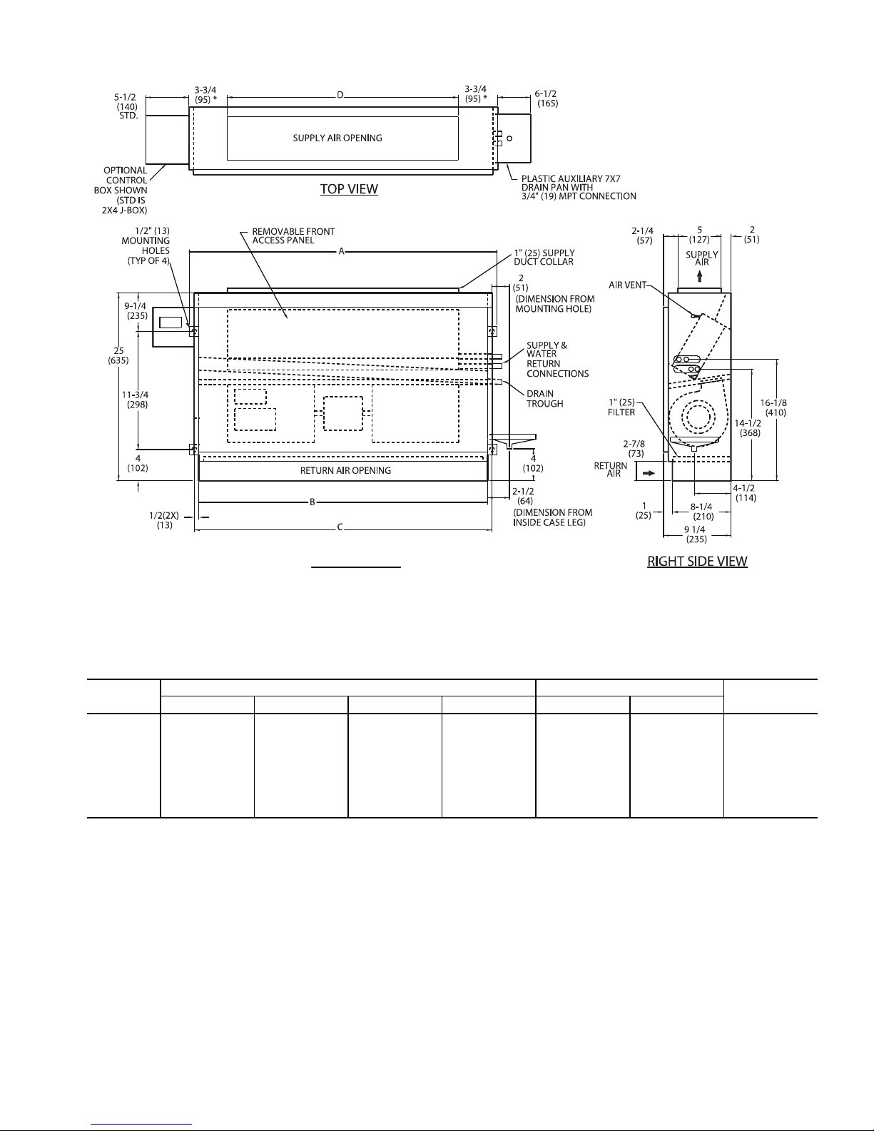
LEGEND
1 — Junction Box
2 — L-shape Drip Lip (optional, shipped loose)
3 — Chilled/Hot Water Supply and Return Connection
4 — Resilient Mounting Grommets with
3
/8-in. Diameter Hole
(typically 4)
5 — Electrical Knockout,
7
/8-in. Diameter
6 — Drain Knockout, 11/2-in. Diameter
7 — Stamped Return Air Grille and 1-in. Filter
8 — Condensate Drain Connection,
7
/8-in. OD
9 — Hinged Bottom Return Air Panel
10 — Supply Duct Collar, 1-in. OD
A42-4149
NOTES:
1. Right hand unit shown; left hand unit opposite.
2. Internal factory valve package and drains may not align with cabinet
knockouts.
3. Dimensions shown in inches (mm). All dimensions are ±
1
/4 inches.
4. Bottom panel is Arctic White polyester powder coat paint.
7
8
9
10
6
5
4
3
2
1
D
Fig. 7 — 42CK Horizontal Cabinet Unit with Telescopic Access Panel,
Front Supply, and Bottom Return Dimensions
11
12
11
10
9
13
NOTES:
1. Right hand unit shown; left hand unit opposite.
2. Internal factory valve package and drains may not align with
cabinet knockouts.
3. Dimensions shown in inches (mm). All dimensions are
±
1
/4 inches.
4. Bottom panel is Arctic White polyester powder coat paint.
*Unit weights are based on dry coils and minimum rows. Weights exclude packaging, valves, and other components.
UNIT
SIZE
NOM
AIRFLOW
(Cfm)
DIMENSIONS (in.) QTY/UNIT BOTTOM
RETURN
FILTER SIZE
(in.)
UNIT WEIGHT*
(lb)
ABCDEFBlowerMotor
02 200 35 16 12
3
/
4
37 32 6 1 1 10 x 231/
2
117
03 300 35 20 8
3
/
4
37 32 6 1 1 10 x 28 122
04 400 41 26 8
3
/
4
43 38 6 2 1 10 x 321/
2
137
06 600 53 31 15
3
/
4
55 50 7 2 1 10 x 37 152
08 800 53 38 8
3
/
4
55 50 7 2 1 10 x 41 157
10 1000 75 52 16
3
/
4
77 72 7 4 2 10 x 541/
2
229
12 1200 75 60 8
3
/
4
77 72 7 4 2 10 x 63 243
a42-4150
LEGEND
1 — Contactor Box
2 — Strip Heater High Limit
3 — Electric Strip Heater Element
4 — L-shape Drip Lip (optional, shipped loose)
5 — Chilled/Hot Water Supply and Return Connection
6 — Resilient Mounting Grommets with
3
/8-in. Diameter Hole
(typically 4)
7 — Electrical Knockout, 7/8-in. Diameter
8 — Drain Knockout, 1
1
/2-in. Diameter
9 — Stamped Return Air Grille and 1-in. Filter
10 — Condensate Drain Connection,
7
/8-in. OD
11 — Hinged Bottom Return Air Panel
12 — Supply Duct Collar, 1-in. OD
13 — Drain Pan
Fig. 8 — 42CK Horizontal Cabinet Unit with Telescopic Access Panel,
Front Supply, Bottom Return, and Heater Dimensions
12
*Unit weights are based on dry coils and minimum rows. Weights exclude packaging, valves, and other components.
UNIT
SIZE
NOM
AIRFLOW
(Cfm)
DIMENSIONS (in.) QTY/UNIT
REAR RETURN
FILTER SIZE (in.)
UNIT WEIGHT*
(lb)
ABCDEFBlowerMotor
02 200 35 16 12
3
/437 32 6 1 1 7 x 21 115
03 300 35 20 8
3
/437 32 6 1 1 7 x 21 120
04 400 41 26 8
3
/443 38 6 2 1 7 x 27 135
06 600 53 31 15
3
/455 50 7 2 1 7 x 38 150
08 800 53 38 8
3
/455 50 7 2 1 7 x 38 155
10 1000 75 52 16
3
/477 72 7 4 2 7 x 52 227
12 1200 75 60 8
3
/477 72 7 4 2 7 x 52 241
a42-4151
NOTES:
1. Right hand unit shown; left hand unit opposite.
2. Internal factory valve package and drains may not align with
cabinet knockouts.
3. Dimensions shown in inches (mm). All dimensions are
±
1
/4 inches.
4. Bottom panel is Arctic White polyester powder coat paint.
LEGEND
1 — Junction Box
2 — 1-in. Ducted Rear Return and 1-in. Filter
3 — L-shape Drip Lip (optional, shipped loose)
4 — Chilled/Hot Water Supply and Return Connection
5 — Resilient Mounting Grommets with
3
/8-in. Diameter Hole
(typically 4)
6 — Electrical Knockout, 7/8-in. Diameter
7 — Drain Knockout, 1
1
/2-in. Diameter
8 — 1-in. Ducted Rear Return and 1-in. Filter
9 — Condensate Drain Connection, 7/8-in. OD
10 — Hinged Bottom Return Air Panel
11 — Supply Duct Collar, 1-in. OD
8
9
10
11
7
6
5
4
3
2
1
Fig. 9 — 42CK Horizontal Cabinet Unit with Telescopic Access Panel,
Front Supply, and Rear Return Dimensions
13
NOTES:
1. Right hand unit shown; left hand unit opposite.
2. Internal factory valve package and drains may not align
with cabinet knockouts.
3. Dimensions shown in inches (mm). All dimensions are
±
1
/4 inches.
4. Bottom panel is Arctic White polyester powder coat paint.
*Unit weights are based on dry coils and minimum rows. Weights exclude packaging, valves, and other components.
UNIT
SIZE
NOM
AIRFLOW
(Cfm)
DIMENSIONS (in.) QTY/UNIT
REAR RETURN
FILTER SIZE (in.)
UNIT WEIGHT*
(lb)
ABCDEFBlowerMotor
02 200 35 16 12
3
/437 32 6 1 1 7 x 21 117
03 300 35 20 8
3
/
4
37 32 6 1 1 7 x 21 122
04 400 41 26 8
3
/
4
43 38 6 2 1 7 x 27 137
06 600 53 31 15
3
/
4
55 50 7 2 1 7 x 38 152
08 800 53 38 8
3
/
4
55 50 7 2 1 7 x 38 157
10 1000 75 52 16
3
/
4
77 72 7 4 2 7 x 52 229
12 1200 75 60 8
3
/
4
77 72 7 4 2 7 x 52 243
a42-4152
LEGEND
1 — Contactor Box
2 — Strip Heater High Limit
3 — Electric Strip Heater Element
4 — 1-in. Ducted Rear Return and 1-in. Filter
5 — L-shape Drip Lip (optional, shipped loose)
6 — Chilled/Hot Water Supply and Return Connection
7 — Resilient Mounting Grommets with
3
/8-in. Diameter Hole
(typically 4)
8 — Electrical Knockout,
7
/8-in. Diameter
9 — Drain Knockout,11/2-in. Diameter
10 — 1-in. Ducted Rear Return and 1-in. Filter
11 — Condensate Drain Connection,
7
/8-in. OD
12 — Hinged Bottom Return Air Panel
13 — Supply Duct Collar, 1-in. OD
14 — Drain Pan
14
Fig. 10 — 42CK Horizontal Cabinet Unit with Telescopic Access Panel,
Front Supply, Rear Return, and Heater Dimensions
14
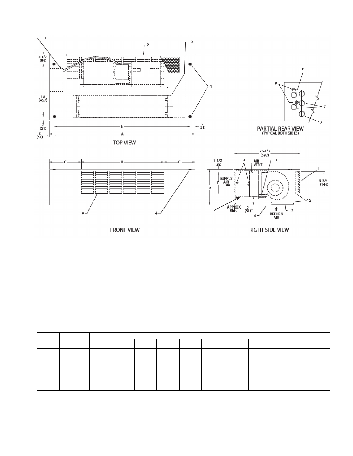
LEGEND
1— Junction Box, 4 in. x 4 in.
2— Drip Lip (optional, shipped loose)
3— Mounting Holes (4), Rubber Grommets
have
3
/8-in. Diameter Hole
4— Piping Knockout, 1
1
/2-in. Diameter
5— Electrical Knockout,
7
/8-in. Diameter
6— Drain Knockout, 1
1
/2-in. Diameter
7— Supply Duct Collar
8— Return Connection,
5
/8-in. OD
9— Optional Rear Return. Consult factory for
collar dimensions
10 — Drain,
7
/8-in. OD
11 — Stamped Bottom Return Air Grille
12 — Filter
13 — Stamped Air Supply Grille
14 — Hinged Bottom Access Panel
15 — Supply Connection,
5
/8-in. OD
*Unit weights are based on dry coils and minimum rows. Weights exclude packaging, valves, and other components.
UNIT
SIZE
NOM
AIRFLOW
(Cfm)
DIMENSIONS (in.) QTY/UNIT
FACE AREA
(sq ft)
UNIT WEIGHT*
(lb)
ADE
Blower Motor
02 200 35 37 32 1 1 0.83 115
03 300 35 37 32 1 1 1.08 120
04 400 41 43 38 2 1 1.35 135
06 600 53 55 50 2 1 1.88 150
08 800 53 55 50 2 1 2.31 155
10 1000 75 77 72 4 2 3.16 227
12 1200 75 77 72 4 2 3.65 241
NOTES:
1. Right hand unit shown; left hand unit opposite. Coil connection
locations are ±5/8-inch.
2. Unit sizes 02 and 03 have one motor, one blower; sizes 04
through 08 have one motor, 2 blowers; sizes 10 and 12 have
2 motors, 4 blowers.
3. Bottom access panel has an Arctic White baked finish.
4. Refer to supply and return connections above for coil stub-out
locations.
5. Not shown: 3-speed fan switch; wall plate;
1
/2-in. fiberglass
insulation on inside of casing, closed cell foam on main drain
pan.
6. For optional coil connections, view 42CA-203-1 using the Fan
Coil Builder.
7. Valve package is factory-installed inside the cabinet when
ordered with the unit (based on component size).
8. Bottom return or bottom supply is an ETO (engineering to order)
request.
9. Dimensions shown in inches (mm).
A42-4107
Fig. 11 — 42CK Horizontal Cabinet Unit with Bottom Supply and Return and Telescopic Access Panel
Dimensions
15
LEGEND
1— Junction Box, 4 in. x 4 in.
2— Strip Heater High Limit
3— Electric Strip Heater Element
4— Drip Lip (optional, shipped loose)
5— Mounting Holes (4), Rubber Grommets
have
3
/8-in. Diameter Hole
6— Piping Knockout, 1
1
/2-in. Diameter
7— Electrical Knockout,
7
/8-in. Diameter
8— Drain Knockout, 1
1
/2-in. Diameter
9— Supply Duct Collar
10 — Optional Rear Return. Consult factory for
collar dimensions.
11 — Drain,
7
/8-in. OD
12 — Stamped Bottom Return Air Grille
13 — Filter
14 — Stamped Air Supply Grille
15 — Hinged Bottom Access Panel
16 — Supply Connection,
5
/8-in. OD
17 — Return Connection,
5
/8-in. OD
NOTES:
1. Right hand unit shown; left hand unit opposite. Coil connection
locations are ±
5
/8-inch.
2. Unit sizes 02 and 03 have one motor, one blower; sizes 04
through 08 have one motor, 2 blowers; sizes 10 and 12 have
2 motors, 4 blowers.
3. Bottom access panel has an Arctic White baked finish.
4. Refer to supply and return connections above for coil stub-out
locations.
5. Not shown: 3-speed fan switch; wall plate;
1
/2-in. fiberglass
insulation on inside of casing; closed cell foam on main drain
pan.
6. For optional coil connections, view 42CA-203-1 using the Fan
Coil Builder.
7. Valve package is factory-installed inside the cabinet when
ordered with the unit (based on component size).
8. Bottom return or bottom supply is an ETO (engineering to order)
request.
9. Dimensions shown in inches (mm).
*Unit weights are based on dry coils and minimum rows. Weights exclude packaging, valves, and other components.
UNIT SIZE
NOM AIRFLOW
(Cfm)
DIMENSIONS (in.) QTY/UNIT
FACE AREA
(sq ft)
UNIT WEIGHT*
(lb)
ADEBlowerMotor
02 200 35 37 32 1 1 0.83 117
03 300 35 37 32 1 1 1.08 122
04 400 41 43 38 2 1 1.35 137
06 600 53 55 50 2 1 1.88 152
08 800 53 55 50 2 1 2.31 157
10 1000 75 77 72 4 2 3.16 229
12 1200 75 77 72 4 2 3.65 243
A42-4108
Fig. 12 — 42CK Horizontal Cabinet with Bottom Supply and Return and Telescopic Access Panel and Electric
Heat Dimensions
16
FRONT VIEW
*Unit weights are based on dry coils and minimum rows. Weights exclude packaging, valves, and other components.
UNIT
SIZE
DIMENSIONS (in.) QTY/UNIT
UNIT WEIGHT*
(lb)
ABCDBlowerMotor
02 24
3
/
16
22 23 16 1 1 42
03 24
3
/
16
22 23 18 1 1 47
04 34
3
/
16
32 33 26 2 1 57
06 44
3
/
16
42 43 36 2 1 77
08 46
3
/
16
44 45 38 2 1 79
10 60
3
/
16
58 59 52 4 2 108
12 68
3
/
16
66 67 60 4 2 127
NOTES:
1. Right hand unit shown; left hand unit opposite.
2. Dimensions shown in inches (mm). All dimensions are
±
1
/4 inches.
a42-4381
Fig. 13 — 42VA Furred-In Vertical Unit Dimensions
17
a42-4382
*Unit weights are based on dry coils and minimum rows. Weights exclude packaging, valves, and other components.
UNIT
SIZE
DIMENSIONS (in.) QTY/UNIT
UNIT WEIGHT*
(lb)
ABCDBlowerMotor
02 24
3
/
16
22 23 16 1 1 42
03 24
3
/
16
22 23 18 1 1 47
04 34
3
/
16
32 33 26 2 1 57
06 44
3
/
16
42 43 36 2 1 77
08 46
3
/
16
44 45 38 2 1 79
10 60
3
/
16
58 59 52 4 2 108
12 68
3
/
16
66 67 60 4 2 127
NOTES:
1. Right hand unit shown; left hand unit opposite.
2. Dimensions shown in inches (mm). All dimensions are
±
1
/4 inches.
Fig. 14 — 42VA Furred-In Unit with Electric Heat Dimensions
18
 Loading...