

Page 1

REVISION 0
QY8-31BF-000
JULY. 2002
COPYRIGHT © 2002 CANON INC. CANON S520X 0702 XX 0.00-0
7109A029AA 220V-240V(EUR)
Page 2

Application
This manual has been issued by Canon Inc. for qualified
person to learn technical theory, installation, maintenance,
and repair of products. This manual covers all localities
where the products are sold. For this reason, there may be
information in this manual that does not apply to your
locality.
Corrections
This manual could include technical inaccuracies or
typographical errors due to improvements or changes in the
products. When changes occur in applicable products or in
the content of this manual, Canon will release technical
information as the need arises. In the event of major
changes in the contents of this manual over a long or short
period. Canon will issue a new editions of this manual.
The following paragraph does not apply to any countries
where such provisions are inconsistent with local low.
Trademarks
The product names and company names described in this
manual are the registered trademarks of the individual
companies.
Copyright
This manual is copyrighted with all rights reserved. Under
the copyright laws, this manual may not be copied,
reproduced or translated into another language, in whole or
in part, without the written consent of Canon Inc.
Copyright © 2002 by Canon Inc.
CANON INC.
i Printer Technical Support Dept.11
16-1, Shimonoge 3-chome, Takatsu-ku, Kawasaki-shi,
Kanagawa 213-8512, Japan
DTP System
This manual was produced on an Apple
®
Power Macintosh
®
G3 personal computer and Canon LBP-2030PS laser beam
printer, final pages were printed on Valityper®4300J.
Parts layout illustrations and Logotypes were created using
MACROMEDIA®FreeHand®7J.
Pattern drawing were scaned by CanoScan 600 scanner with
Adobe®photoshop®.
Documents and page layouts were created using
QuarkXpress®3.3J.
Parts lists were created using Helix Tecnologies®Herix
Xpress®and converted to EPS files.
Page 3

I
I.
CONTENTS
A. ILLUSTRATION INDEX
B. PARTS LAYOUT & PARTS LIST
C. OPTIONS & CONSUMABLES
D. SCREWS & WASHERS LIST
E. TOOL
F. NUMERICAL INDEX
Page 4

II
II.
ABOUT THIS MANUAL
A. ILLUSTRATION INDEX
For illustration index, the parts layout
illustrations in this parts catalog are
listed in abbreviated form in order of
illustration number to identify the pages
they appear on. To find an illustration of
a part, see the ILLUSTRATION INDEX.
B. PARTS LAYOUT & PARTS LIST
Parts layout illustration
a) Parts search
Find a part from the parts layout
illustration and find its key number
from the parts list to identify the part
number and name. For screws, nuts,
washers, lock washers, pins, spacers,
see SCREWS &WASHERS LIST.
Note: If parts have the same or similar
shape but different specifications,
their key number is assigned to
several part numbers and names
in the parts list.
b) Parts replacement procedure
To replace parts, the parts layout
illustrations have figure numbers
according to the disassembly procedure
of the product. The parts that require
careful work are shown the illustration.
Parts list
a) FIGURE & KEY No.
The FIGURE & KEY No. column
corresponds to the key numbers
assigned to the parts in the parts
layout illustration.
It also corresponds to the part locations
printed on the PC board.
b) PART NUMBER
The PART NUMBER column gives the
part numbers corresponding to the key
numbers. To order a part, indicate the
part number clearly.
Note: Parts marked NPN are not
service parts.
c) RANK
The service parts with N in the RANK
column are order parts.
d) QTY
The QTY column gives the number of
parts in the corresponding components
layout illustration.
e) DESCRIPTION
The DESCRIPTION column gives the
part names in English.
To order a part, indicate the part
name, too.
C. OPTIONS & CONSUMABLES
These are illustrations and a list of units
that can be used as optional consumable
equipments.
D. SCREWS & WASHERS LIST
This is a list of screws, nuts, washers,
lock washers, pins, and spacers.
The QTY column does not give the
number of parts used.
E. TOOL LIST
This is a list of tools used for servicing
products.
F. NUMERICAL INDEX
All the parts listed in this parts catalog
are arranged in order of part number.
You can identify part locations and
names from the NUMERICAL INDEX.
Page 5

III
This page intentionally left blank
Page 6
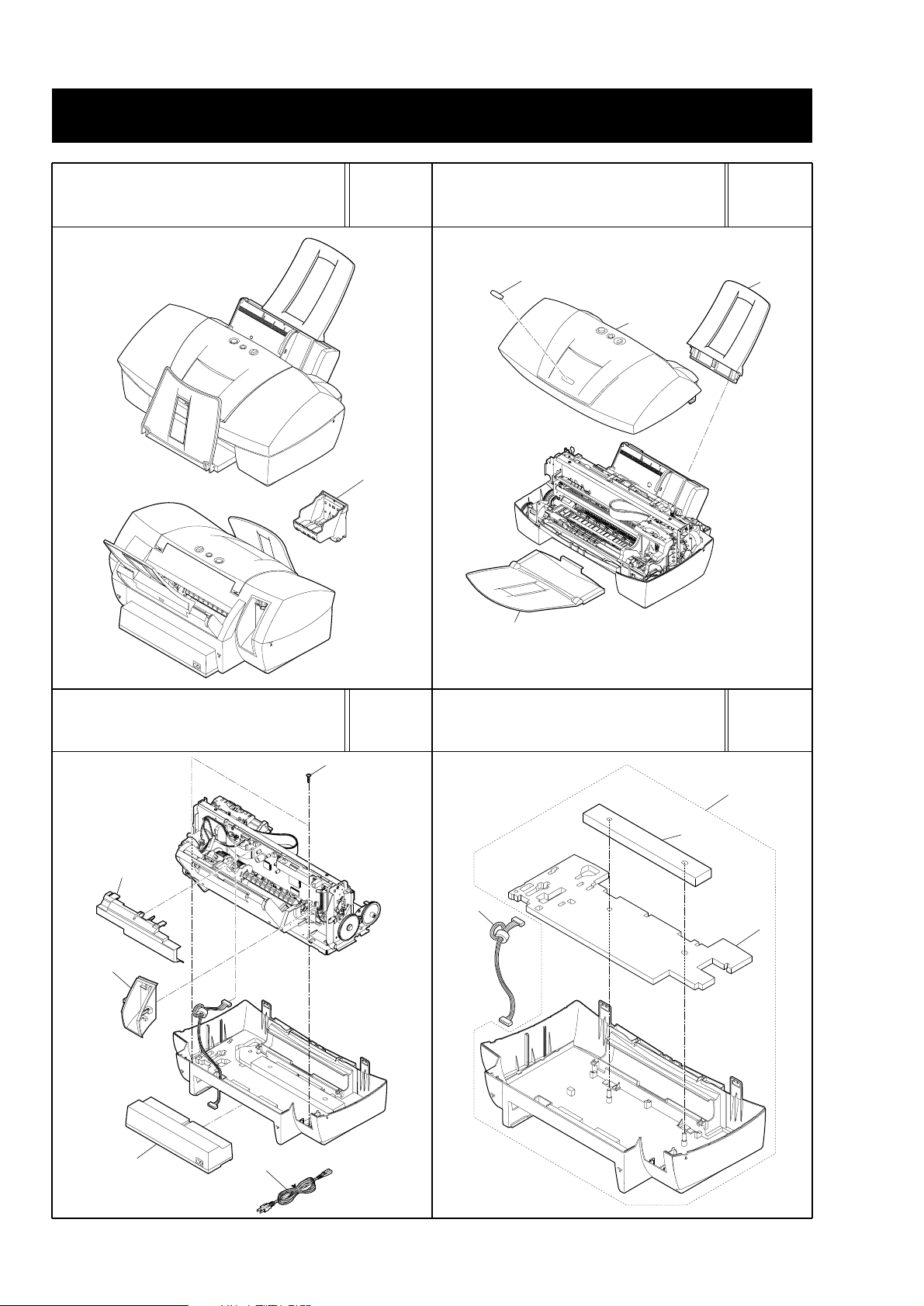
TRAY & COVER
PRINTER & PRINT HEAD
2
1
4
3
1
2
3
4
S1
1
2
4
1
3
See Page
B - 3
FIGURE 2
See Page
B - 5
AC ADAPTER
FIGURE 3
See Page
B - 7
FIGURE 1
See Page
B - 1
A.
ILLUSTRATION INDEX
A-1
FIGURE 4
WASTE INK ABSORBER
Page 7

LOGIC BOARD & ASF UNIT
CARRIAGE PARTCARRIAGE UNIT
1
3
2
S2
S2
S2
S3
S2
S2
1
3
9
4
2
5
8
S2
6
7
S2
4
1
2
3
5
S5
1
S2
S4
2
S2
FIGURE 7
See Page
B - 13
FIGURE 8
See Page
B - 15
See Page
B - 11
PURGE UNIT
FIGURE 6
See Page
B - 9
FIGURE 5
A-2
Page 8
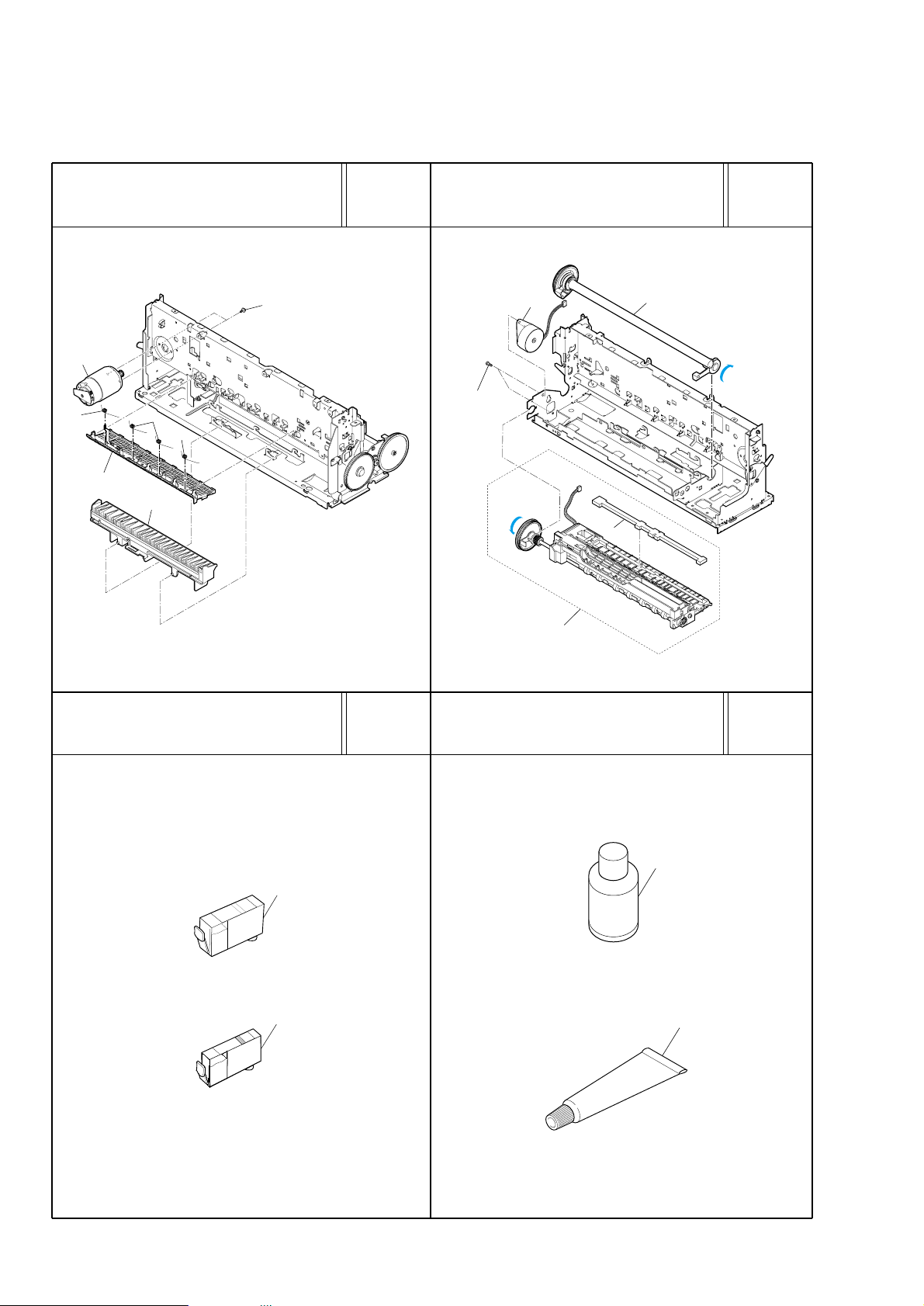
PRESSURE ROLLER ASS'Y
TOOLOPTION& CONSUMABLES
PAPER FEED UNIT
T2
T1
F
L
O
I
L
1
2
S6
1
2
3
4
4
2
1
1
1
3
S2
FIGURE 11
See Page
C - 1
FIGURE 12
See Page
E - 1
FIGURE 9
See Page
B - 17
FIGURE 10
See Page
B - 19
A-3
Page 9

A-4
This page intentionally left blank
Page 10
B-1
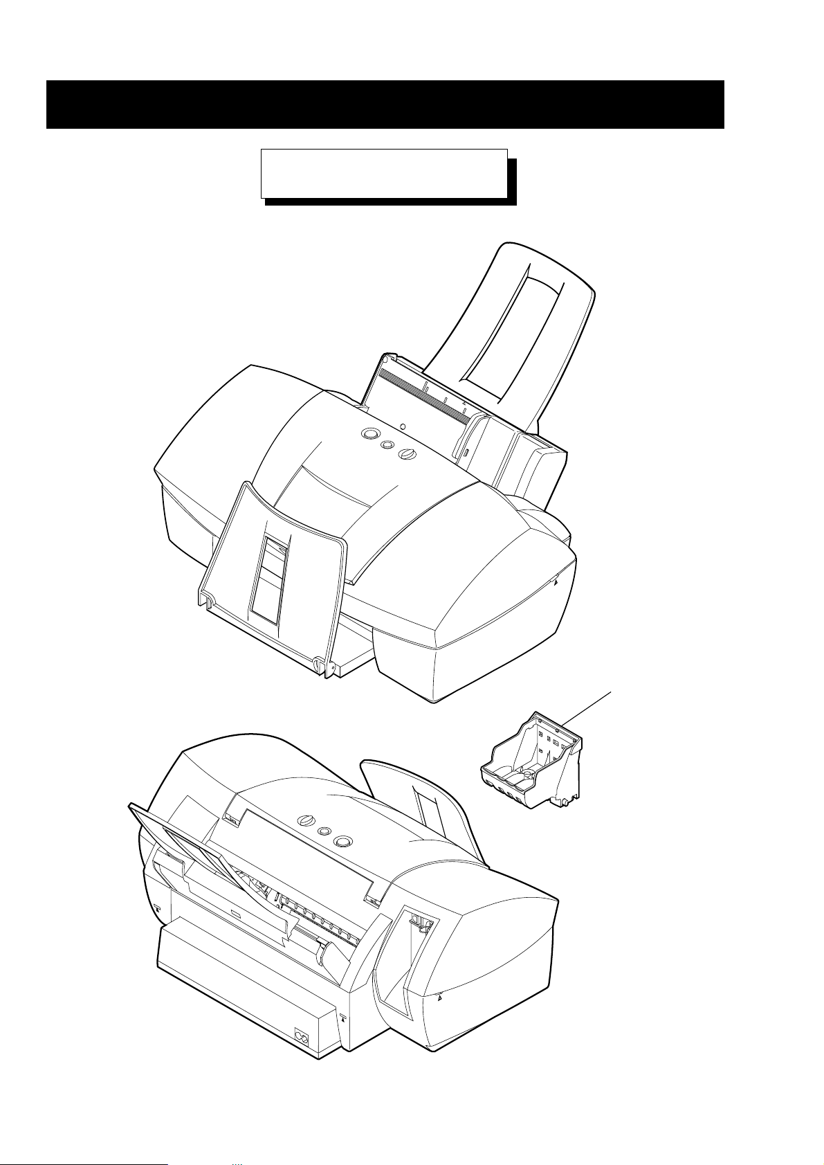
1
PRINTER & PRINT HEAD
FIGURE 1
B.
PARTS LAYOUT & PARTS LIST
Page 11

B-2
FIGURE
&
KEY NO.
1 - 1 QY6-0034-000 1 PRINT HEAD
PART NUMBER
R
Q
A
T
N
Y
K
DESCRIPTION REMARKS
Page 12

B-3
2
4
1
3
FIGURE 2
TRAY & COVER
Page 13

B-4
FIGURE
&
PART NUMBER
KEY NO.
2 - 1 QG4-0159-000 1 OUT PUT TRAY UNIT
2 QA4-0686-000 1 SUPPORT, PAPER
3 QG4-0161-000 1 UPPER COVER UNIT
4 QA4-0682-000 1 PLATE, MODEL NAME
R
Q
A
T
N
Y
K
DESCRIPTION REMARKS
Page 14

B-5
1
2
3
4
S1
FIGURE 3
AC ADAPTER
Page 15

B-6
FIGURE
&
PART NUMBER
KEY NO.
3 - 1 QA4-0109-000 1 COVER, LOGIC BOARD
2 QA4-0519-000 1 COVER, I/F
3 QH3-3558-000 1 AC ADAPTER: 220V-240V 50/60HZ
4 WT3-5132-000 1 CORD, POWER 220V-240V
R
Q
A
T
N
Y
K
DESCRIPTION REMARKS
Page 16

B-7
2
1
4
3
FIGURE 4
WASTE INK ABSORBER
Page 17

B-8
FIGURE
&
PART NUMBER
KEY NO.
4 - 1 QG2-3329-000 1 DC CONNECTOR ASS'Y (WITH CABLE)
2 QG4-0150-000 1 BOTTOM CASE UNIT
3 QA4-0006-000 1 ABSORBER, INK
4 QA4-0662-000 1 ABSORBER, INK
R
Q
A
T
N
Y
K
DESCRIPTION REMARKS
Page 18

B-9
1
3
2
S2
S2
S2
S3
S2
S2
FIGURE 5
LOGIC BOARD & ASF UNIT
Page 19

B-10
FIGURE
&
PART NUMBER
KEY NO.
5 - 1 QG4-0092-030 1 SHEET FEEDER UNIT
2 QA4-0168-000 1 PLATE, ROM COVER
3 QG2-3409-000 1 LOGIC BOARD ASS'Y
R
Q
A
T
N
Y
K
DESCRIPTION REMARKS
Page 20

B-11
1
S2
S4
2
S2
FIGURE 6
PURGE UNIT
Page 21

B-12
FIGURE
&
PART NUMBER
KEY NO.
6 - 1 QG4-0022-000 1 WIPER CLEANER ASS'Y
2 QG4-0257-000 1 PURGE UNIT
R
Q
A
T
N
Y
K
N
DESCRIPTION REMARKS
Page 22

B-13
1
3
9
4
2
5
8
S2
6
7
S2
FIGURE 7
CARRIAGE UNIT
Page 23

B-14
FIGURE
&
PART NUMBER
KEY NO.
7 - 1 QA4-0019-000 1 FRAME, CARRIAGE GUIDE
2 QA4-0782-000 1 CLIP, SHAFT
3 QA4-0633-000 1 CLIP, SHAFT
4 QA4-0011-000 1 FILM, TIMING SLIT STRIP
5 QA4-0627-000 1 SHAFT, CARRIAGE
6 QG4-0149-000 1 CARRIAGE UNIT
7 QS4-2082-000 1 SPRING, COIL
8 QF4-0004-000 1 IDLER, ROLLER ASS'Y
9 QA4-0631-000 1 SPRING, LEAF
R
Q
A
T
N
Y
K
N
N
DESCRIPTION REMARKS
Page 24

B-15
4
1
2
3
5
S5
FIGURE 8
CARRIAGE PART
Page 25

B-16
FIGURE
&
PART NUMBER
KEY NO.
8 - 1 QH2-2438-000 1 CARRIAGE RIBBON CABLE
2 QH2-2439-000 1 CARRIAGE RIBBON CABLE
3 QH2-2440-000 1 CARRIAGE RIBBON CABLE
4 QG2-3333-000 1 CARRIAGE BOARD ASS'Y
5 QA4-0636-000 1 PLATE, HEAD GUARD, R
R
Q
A
T
N
Y
K
DESCRIPTION REMARKS
Page 26

B-17
4
2
1
1
1
3
S2
FIGURE 9
PRESSURE ROLLER ASS'Y
Page 27

B-18
FIGURE
&
PART NUMBER
KEY NO.
9 - 1 QA4-0111-000 4 SPRING, TORSION
2 QG4-0131-000 1 PRESSURE ROLLER ASS'Y
3 QF4-0071-000 1 PAPER FEED ASS'Y
4 QH4-4431-000 1 MOTOR, CARRIAGE
R
Q
A
T
N
Y
K
N
DESCRIPTION REMARKS
Page 28

B-19
S6
1
2
3
4
FIGURE 10
PAPER FEED UNIT
Page 29

B-20
FIGURE
&
PART NUMBER
KEY NO.
10 - 1 QG4-0154-020 1 PLATEN UNIT
2 QA4-0612-000 1 ABSORBER, INK
3 QF4-0083-000 1 PAPER FEED MOTOR ASS'Y
4 QF4-0085-000 1 FEED ROLLER ASS'Y
R
Q
A
T
N
Y
K
N
DESCRIPTION REMARKS
Page 30

1
2
C-1
FIGURE 11
OPTION & CONSUMABLES
C.
OPTIONS & CONSUMABLES
Page 31

C-2
FIGURE
&
PART NUMBER
KEY NO.
11 - 1 NPN 1 BLACK INK TANK BCI-3eBK CONSUMABLES
2 NPN 1 CYAN INK TANK BCI-3eC CONSUMABLES
NPN 1 MAGENTA INK TANK BCI-3eM CONSUMABLES
NPN 1 YELLOW INK TANK BCI-3eY CONSUMABLES
R
Q
A
T
N
Y
K
DESCRIPTION REMARKS
Page 32

D-1
D.
SCREWS & WASHERS LIST
FIGURE
&
KEY NO.
S - 1 XA9-1258-000 SCREW, TAP, WASHER HEAD, M3X12
2 XB6-7300-607 SCREW, TP: M3 x 6 MM
3 XB1-2301-207 SCREW, M3x12
4 XB4-7300-809 SCREW, B-TIGHT: M3 X 8 MM
5 XB4-7301-009 SCREW, B-TIGHT: M3 X 10 MM
6 XB1-2300-407 SCREW, M3X4
PART NUMBER
R
Q
A
T
N
Y
K
DESCRIPTION REMARKS
Page 33

D-2
This page intentionally left blank
Page 34

T2
T1
F
L
O
I
L
E-1
FIGURE 12
TOOL
E.
TOOL
Page 35

E-2
FIGURE
&
KEY NO.
T - 1 QY9-0057-000 1 LUBE, FLOIL KG107A, OIL
2 CK-0562-000 1 GREASE, MOLYKOTE PG-641
PART NUMBER
R
Q
A
T
N
Y
K
DESCRIPTION REMARKS
Page 36

F-1
F.
NUMERICAL INDEX
PART
NUMBER
CK-0562-000 T - 2 GREASE, MOLYKOTE PG-641
QA4-0006-000 4 - 3 ABSORBER, INK
QA4-0011-000 7 - 4 FILM, TIMING SLIT STRIP
QA4-0019-000 7 - 1 FRAME, CARRIAGE GUIDE
QA4-0109-000 3 - 1 COVER, LOGIC BOARD
QA4-0111-000 9 - 1 SPRING, TORSION
QA4-0168-000 5 - 2 PLATE, ROM COVER
QA4-0519-000 3 - 2 COVER, I/F
QA4-0612-000 10 - 2 ABSORBER, INK
QA4-0627-000 7 - 5 SHAFT, CARRIAGE
QA4-0631-000 7 - 9 SPRING, LEAF
QA4-0633-000 7 - 3 CLIP, SHAFT
QA4-0636-000 8 - 5 PLATE, HEAD GUARD, R
QA4-0662-000 4 - 4 ABSORBER, INK
QA4-0682-000 2 - 4 PLATE, MODEL NAME
QA4-0686-000 2 - 2 SUPPORT, PAPER
QA4-0782-000 7 - 2 CLIP, SHAFT
QF4-0004-000 7 - 8 IDLER, ROLLER ASS'Y
QF4-0071-000 9 - 3 PAPER FEED ASS'Y
QF4-0083-000 10 - 3 PAPER FEED MOTOR ASS'Y
QF4-0085-000 10 - 4 FEED ROLLER ASS'Y
QG2-3329-000 4 - 1 DC CONNECTOR ASS'Y
QG2-3333-000 8 - 4 CARRIAGE BOARD ASS'Y
QG2-3409-000 5 - 3 LOGIC BOARD ASS'Y
QG4-0022-000 6 - 1 WIPER CLEANER ASS'Y
QG4-0092-030 5 - 1 SHEET FEEDER UNIT
QG4-0131-000 9 - 2 PRESSURE ROLLER ASS'Y
QG4-0149-000 7 - 6 CARRIAGE UNIT
QG4-0150-000 4 - 2 BOTTOM CASE UNIT
QG4-0154-020 10 - 1 PLATEN UNIT
QG4-0159-000 2 - 1 OUT PUT TRAY UNIT
QG4-0161-000 2 - 3 UPPER COVER UNIT
QG4-0257-000 6 - 2 PURGE UNIT
QH2-2438-000 8 - 1 CARRIAGE RIBBON CABLE
QH2-2439-000 8 - 2 CARRIAGE RIBBON CABLE
QH2-2440-000 8 - 3 CARRIAGE RIBBON CABLE
QH3-3558-000 3 - 3 AC ADAPTER: 220V-240V 50/60HZ
QH4-4431-000 9 - 4 MOTOR, CARRIAGE
QS4-2082-000 7 - 7 SPRING, COIL
QY6-0034-000 1 - 1 PRINT HEAD
QY9-0057-000 T - 1 LUBE, FLOIL KG107A, OIL
WT3-5132-000 3 - 4 CORD, POWER
XA9-1258-000 S - 1 SCREW, TAP, WASHER HEAD, M3X12
XB1-2300-407 S - 6 SCREW, M3X4
XB1-2301-207 S - 3 SCREW, M3x12
XB4-7300-809 S - 4 SCREW, B-TIGHT: M3 X 8 MM
XB4-7301-009 S - 5 SCREW, B-TIGHT: M3 X 10 MM
XB6-7300-607 S - 2 SCREW, TP: M3 x 6 MM
FIGURE &
KEY NO.
DESCRIPTION
Page 37

CANON INC.
 Loading...