

Canon S450 Parts Catalog
REVISION 0
QY8-31SG-000
JULY 2000
COPYRIGHT © 2000 CANON INC. CANON S450 0700 XX 0.00-0 PRINTED IN JAPAN (IMPRIME AU JAPON)
Q30-3400-720 120V(CCSI)
Q30-3400-721 120V(CAN)
Q30-3400-722 120V(LATIN LV)
Q30-3400-723 220V-240V(LATIN HV)
Q30-3400-724 120V(CCSI W/O HEAD)
Q30-3400-725 120V(CAN W/O HEAD)
Q30-3400-730 220V-240V(EUR)
Q30-3400-731 220V-240V(GER)
Q30-3400-732 220V-240V(FRN)
Q30-3400-733 220V-240V(ASIA HV)
Q30-3400-740 220V-240V(AUST)
Q30-3400-760 220V-240V(KRN)
Q30-3400-780 220V-240V(UK)
Q30-3402-723 120V(TWN)
Q30-3402-750 220V-240V(HK)

0700 XX 0.00-0


Application
This manual has been issued by Canon Inc. for qualified
person to learn technical theory, installation, maintenance,
and repair of products. This manual covers all localities
where the products are sold. For this reason, there may be
information in this manual that does not apply to your
locality.
Corrections
This manual could include technical inaccuracies or
typographical errors due to improvements or changes in the
products. When changes occur in applicable products or in
the content of this manual, Canon will release technical
information as the need arises. In the event of major
changes in the contents of this manual over a long or short
period. Canon will issue a new editions of this manual.
The following paragraph does not apply to any countries
where such provisions are inconsistent with local low.
Trademarks
The product names and company names described in this
manual are the registered trademarks of the individual
companies.
Copyright
This manual is copyrighted with all rights reserved. Under
the copyright laws, this manual may not be copied,
reproduced or translated into another language, in whole or
in part, without the written consent of Canon Inc.
Copyright © 2000 by Canon Inc.
CANON INC.
BJ Printer Technical Support Dept.11
16-1, Shimonoge 3-chome, Takatsu-ku, Kawasaki-shi,
Kanagawa 213-8512, Japan
DTP System
This manual was produced on an Apple®Power Macintosh
®
G3 personal computer and Canon LBP-2030PS laser beam
printer, final pages were printed on Valityper®4300J.
A Canon mo-5001S™Magneto-optical Storage Subsystem
with mo-502M™Magneto-Optical Storage Disk Cartridge
and mo-IF2™Machitosh®interface kit were used for storing
large volumes of page layout, graphic and parts list data for
this manual.
Parts layout illustrations and Logotypes were created using
MACROMEDIA®FreeHand®7J.
Pattern drawing were scanned by CanoScan 600 scanner
with Adobe®photoshop®.
Documents and page layouts were created using
QuarkXpress®3.3J.
Parts lists were created using Helix Tecnologies®Herix
Xpress®and converted to EPS files.

I
I.
CONTENTS
A. PARTS LAYOUT & PARTS LIST
B. OPTIONS & CONSUMABLES
C. SCREWS & WASHERS LIST
D. TOOL
E. NUMERICAL INDEX

II
II.
ABOUT THIS MANUAL
A. PARTS LAYOUT & PARTS LIST
Parts layout illustration
a) Parts search
Find a part from the parts layout
illustration and find its key number
from the parts list to identify the part
number and name. For screws, nuts,
washers, lock washers, pins, spacers,
see SCREWS &WASHERS LIST.
Note: If parts have the same or similar
shape but different specifications,
their key number is assigned to
several part numbers and names
in the parts list.
b) Parts replacement procedure
To replace parts, the parts layout
illustrations have figure numbers
according to the disassembly procedure
of the product. The parts that require
careful work are shown the illustration.
Parts list
a) FIGURE & KEY No.
The FIGURE & KEY No. column
corresponds to the key numbers
assigned to the parts in the parts
layout illustration.
It also corresponds to the part locations
printed on the PC board.
b) PART NUMBER
The PART NUMBER column gives the
part numbers corresponding to the key
numbers. To order a part, indicate the
part number clearly.
Note: Parts marked NPN are not
service parts.
c) RANK
The service parts with N in the RANK
column are order parts.
d) QTY
The QTY column gives the number of
parts in the corresponding components
layout illustration.
e) DESCRIPTION
The DESCRIPTION column gives the
part names in English.
To order a part, indicate the part name,
too.
B. OPTIONS & CONSUMABLES
These are illustrations and a list of units
that can be used as optional consumable
equipments.
C. SCREWS & WASHERS LIST
This is a list of screws, nuts, washers,
lock washers, pins, and spacers.
The QTY column does not give the
number of parts used.
D. TOOL LIST
This is a list of tools used for servicing
products.
E. NUMERICAL INDEX
All the parts listed in this parts catalog
are arranged in order of part number.
You can identify part locations and
names from the NUMERICAL INDEX.

III
A-1
4
5
6
3
1
2
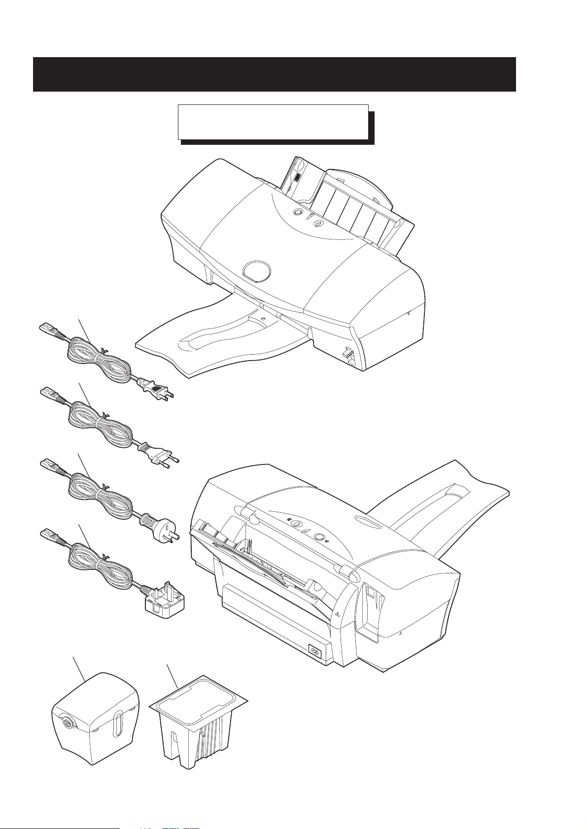
PRINTER & ACCESSORIES
FIGURE 1
A.
PARTS LAYOUT & PARTS LIST

A-2
FIGURE
&
KEY NO.
1 - 1
2
3
4
5
6
R
PART NUMBER
A
N
K
QG5-1290-000 1
NPN 1
WT3-5131-000 1
WT3-5132-000 1
WT3-5121-000 1
WT3-5133-000 1
N
Q
T
DESCRIPTION REMARKS
Y
BJ CARTRIDGE CONTAINER
COLOR BJ CARTRIDGE PACK CONSUMABLES
CORD, POWER 100V-120V
CORD, POWER 220V-240V
CORD, POWER 220V-240V(UK)
CORD, POWER 220V-240V(AUST)
A-3
1
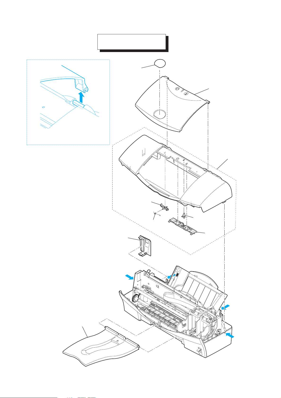
How to remove KEY No. 2
2
3
4
7
8
9
6
5
FIGURE 2
FRONT COVER

A-4
FIGURE
&
KEY NO.
2 - 1
2
3
4
5
6
7
8
9
R
PART NUMBER
A
N
K
QB1-4578-000 1
QB1-4645-000 1
QB1-4660-000 1
QG5-1516-000 1
QB1-4642-000 1
QB1-4664-000 1
QB1-4585-000 1
QB1-4584-000 1
QB1-4644-000 1
Q
T
DESCRIPTION REMARKS
Y
OUTPUT TRAY
COVER, FRONT
PLATE, MODEL NAME
UPPER COVER UNIT
BUTTON, PUSH
SPRING, BUTTON
GUIDE, INDICATOR
BUTTON, PUSH
COVER, I/F
A-5
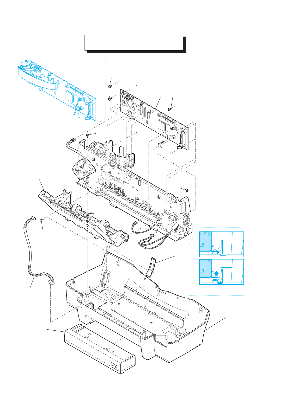
How to install KEY No. 5
3
4
S3
S2
S1
S2
How to remove Printer Unit
5
S2
S1
S2
1
2
6
FIGURE 3
ASF UNIT & LOGIC BOARD
 Loading...