

Page 1

PIXMA MP 780
PIXMA MP 750
SER VICE
MANUAL
Canon
Copyright 2004, Canon U.S.A. This technical publication is the proprietary and confidential information of Canon U.S.A. which
shall be retained for reference purposes by Authorized Service Facilities of Canon U.S.A. Its unauthorized use is prohibited.
Page 2

PIXMA MP750/780
SERVICE
MANUAL
REVISION 0
PIXMA MP750 H12-4562 120V USA
PIXMA MP750 H12-4563 230V EMB
PIXMA MP750 H12-4564 230V GB
PIXMA MP750 H12-4565 230V EUM
PIXMA MP750 H12-4566 120V CND
PIXMA MP750 H12-4568 230V AUS
PIXMA MP780 H12-4582 120V USA
PIXMA MP780 H12-4583 230V EE/NE
PIXMA MP780 H12-4584 230V GB/ME/NORD/ZA
PIXMA MP780 H12-4585 230V AT/CH/DE
PIXMA MP780 H12-4586 230V WEST
PIXMA MP780 H12-4587 120V CND/LTN
PIXMA MP780 H12-4588 230V AUS
PIXMA MP780 H12-4589 230V AE
PIXMA MP780 H12-4597 230V CHN
HY8-13A3-000
COPYRIGHT2004 CANON INC. CANON PIXMA MP750/780 NOV. 2004
Page 3

Scope
This manual has been issued by Canon Inc., to provide the service technicians of this product with the
information necessary for qualified persons to learn technical theory, installation, maintenance, and repair of
products. The manual covers information applicable in all regions where the product is sold. For this reason, it
may contain information that is not applicable to your region.
Revision
This manual could include technical inaccuracies or typographical errors due to improvements or changes made
to the product. When changes are made to the contents of the manual, Canon will release technical information
when necessary. When substantial changes are made to the contents of the manual, Canon will issue a revised
edition.
The following do not apply if they do not conform to the laws and regulations of the region where the manual or
product is used:
Trademarks
Product and brand names appearing in this manual are registered trademarks or trademarks of the respective
holders.
Copyright
All rights reserved. No parts of this manual may be reproduced in any form or by any means or translated into
another language without the written permission of Canon Inc., except in the case of internal business use.
Copyright © 2004 by Canon Inc.
CANON INC.
Inkjet MFP Quality Assurance Div.
5-1 Hakusan 7-Chome, Toride-city, Ibaraki 302-8501, Japan
Page 4

I. MANUAL OUTLINE
This manual consists of the following three parts to provide information necessary to service the PIXMA
MP750/MP780:
Part 1: Maintenance
Information on maintenance and troubleshooting of the PIXMA MP750/MP780
Part 2: Technical Reference
New technology and technical information such as FAQ's (Frequently Ask ed Questions) of th e PIXMA
MP750/MP780
Part 3: Appendix
Block diagrams and pin layouts of the PIXMA MP750/MP780
Reference:
This manual does not provide sufficient information for disassembly and reassembly procedures. Refer
to the graphics in the separate Parts Catalog.
Page 5

II. TABLE OF CONTENTS
Part 1: MAINTENANCE
1 - 1 1. MAINTENANCE
1 - 1 1-1. Adjustment, Periodic Maintenance, Periodic Replacement Parts, and Replacement
Consumables by Service Engineer
1 - 3 1-2. Customer Maintenance
1 - 4 1-3. Product Life
1 - 4 1-4. Special Tools
1 - 5 1-5. Serial Number Location
1 - 6 2. LIST OF ERROR DISPLAY / INDICATION
1 - 6 2-1. Users Error Messege
1 - 9 2-2. Users Error Code
1 - 9 2-3. Service Call Errors
1 - 14 2-4. New Error Codes and Recovery Methods
1 - 16 2-5. Warnings
1 - 17 2-6. Troubleshooting by Symptom
1 - 22 2-7 Processing Communication Problems (MP780 only)
1 - 22 2-7-1 Initial Identification of Problems
1 - 24 2-7-2 Procedures for Processing Communication Problems
1 - 25 2-7-3 Procedures for Processing Communication Problems with Canon Facsimile.
1 - 26 2-7-4 Procedures for Processing Communication Problems with other Manufacturer's
Facsimiles.
1 - 27 3. REPAIR
1 - 27 3-1. Notes on Service Part Replacement (and Disassembling / Reassembling)
1 - 30 3-2. Special Notes on Repair Servicing
1 - 30
3-2-1 Flexible Cable and Harness Wiring, Connection
1 - 33 3-3. Adjustment / Settings
1 - 33 3-3-1 Paper Feed Motor Adjustment
1 - 33 3-3-2 Gear Phase Adjustment
1 - 35 3-3-3 Lift Cam Shaft Ass’y Adjustment
1 - 36 3-3-4 Solenoid Cam Spring Location
1 - 36 3-3-5 Carriage Shaft Clip Location
1 - 37 3-3-6 White Sheet Location
1 - 39 3-3-7 Grease Application
1 - 41 3-3-8 Waste Ink Counter Setting
1 - 41 3-4. User Data Flow
1 - 46 3-5. Service Switches
1 - 46 3-5-1 Hardware Switches
1 - 46 3-5-2 Service Data Setting
1 - 47 3-5-3 Service Data Registration / Setting Method
1 - 48 3-5-4 Service Data Flowchart
1 - 54 3-5-5 Explanation of service data
1 - 55 3-5-6 New SSSWs / parameters added to this model
1 - 60 3-5-7 SSSW Default Setting
1 - 78 3-6. Test Mode / Factory Mode
1 - 78 3-6-1 Test Mode / Factory Mode Overview
Page 6

1 - 79 3-6-2 Test Mode Menu
1 - 80 3-6-3 Factory Mode
1 - 81 3-6-4 Operation Panel Test
1 - 83 3-6-5 Print Test
1 - 85 3-6-6 CD-R Calibration (230V only)
1 - 85 3-7. Upgrading the version of SPCNT Flash ROM
1 - 86 3-8. Verification Items
1 - 86 3-8-1 Users Report Service Test Print
1 - 87 3-8-2 Service EEPROM Information Print
1 - 88 3-8-3 System Data List (MP780 only)
1 - 95 3-8-4 System Dump List (MP780 only)
1 - 99 3-8-5 Service Activity Report (sending/receiving) (MP780only)
1 - 101 3-8-6 EEPROM Information Print
1 - 102 4. Cleaning Your Machine
1 - 102 4-1 Caution
1 - 102 4-2 Cleaning the Exterior
1 - 102 4-3 Cleaning the Scan Area
1 - 103 4-4 Cleaning the Interior
1 - 103 4-5 Cleaning the Feeder Cover
1 - 104 4-6 Cleaning the Rubber Sheet / Paper Feed Rollor / Separate Rollor
1 - 104 4-7 Cleaning the Paper Feed Rollor
1 - 105 4-8 Cleaning the Bottom Plate
1 - 106 5. Transportation
Part 2: TECHNICAL REFERENCE
2 - 1 1. New Technologies
2 - 3 2. Cleaning Mode and Amount of Ink Purged
2 - 5 3. Print Mode
2 - 9 4. FAQ (Problems Specific to the MP750/MP780 and C orrecti ve Ac ti ons)
Part 3: APPENDIX
3 - 1 1. Wiring Diagram
3 - 2 2. Circuit Diagram
3 - 3 2-1 NCU Circuit Diagram1
3 - 4 2-2 NCU Circuit Diagram2
3 - 5 2-3 Relay Circuit Diagram
3 - 6 3. Specification
Page 7

Part 1
Maintenance
Page 8

1. MAINTENANCE
1-1 Adjustment, Periodic Maintenance, Periodic Replacement Parts, and
Replacement Consumables by Service Engineer
(1) Adjustment
Adjustment Timing Purpose Tool
ALL CLEAR
(EEPROM
initialization)
*1
TYPE settings
(EEPROM
settings)
*1
Waste ink
counter resetting
(EEPROM
settings)
Waste ink
counter setting
(EEPROM
initialization)
CD-R sensor /
automatic print
head alignment
sensor correction
(EEPROM
settings)
(230V only)
At SPCNT BOARD ASS’Y
replacement
-At SPCNT BOARD ASS’Y
replacement
-At excecuting All clear
At bottom case unit
replacement
At ink absorber INK
ABSORBER
(HY7-2885/2886/2887/28
88/2889/2890/2891/2953)
At SPCNT BOARD ASS’Y
replacement
At SPCNT BOARD ASS’Y
replacement
At carriage unit
replacement
To initialize settings other
than the following
-1-touch speed dialing
(MP780 only)
-Service/User soft SW
(MP780 only)
-Tx/Rx infomation
(MP780 only)
-Various counters
-TYPE Setting
-To set the type
-To set the destination
To reset the waste ink
counter.
Waste ink counter setting None
To correct the CD-R and
automatic print head
alignment sensor.
None
To initialize
the settings,
select #8
CLEAR–ALL
in the service
mode
None
Select #5
TYPE in the
service mode
Power SW
OFF/ON*1
None
Select #7
PRINTER in
the service
mode, and
input “0” at #5
INK ABS
CAPA.
Print out the
EEPROM
information,
and select #7
PRINTER in
the service
mode.
Then, register
at #5 INK ABS
CAPA.
None.
(Correction
performed
through
FACTORY
MODE-[2]PRI
NTER-SHUK
KEN at the
same time as
printing.)
Approx
time
1 min
1 min
1min
1 imn
1 min
1 - 1
Page 9

Adjustment Timing Purpose Tool
Print head
alignment
Paper feed motor
position
adjustment*
*2
Grease
application
Note: DO NOT loosen the red screws on both sides of the main chassis, securing the carriage shaft
positioning.
*1: When SPCNT BOARD ASS’Y is replaced, be sure to select the settings of [#8CLEAR]-[ALL]
and [#5TYPE] in Service Mode, and turn the power OFF/ON with the Power button (Software
Power: OFF/ON). DO NOT turn the power OFF/ON by removing and inserting the power code
(Hardware Power: OFF/ON). In this case, data may not be written correctly.
*2: Red screws of paper feed motor
The red screws securing the paper feed motor may be loosened only at replacement of the paper
feed motor unit.
- At print head
replacement
- At SPCNT BOARD ASS’Y
replacement
-At paper feed motor unit
replacement
-At carriage unit
replacement
-At chassis' upper gear
replacement
-At LIFT CAM SHAFT
replacement
To ensure accurate dot
placement.
To adjust the belt tension.
(Position the paper
feed motor so that the belt
is stretched tight.)
-To maintain sliding
properties of the carriage,
carriage shaft, and shaft
lift.
-To protect the chassis'
upper gear.
-To LIFT CAM SHAFT
replacement
None.(Main
body
buttons)
Computer
(settings via
the printer
driver)
None
For the
adjustment,
refer to [3-3
Adjustment/Se
ttings
(1) PAPER
FEED
MOTOR
Installation
Adjustment.
-FLOIL
KG-107A
-MOLYKOTE
HP300
Approx
time
2 min
2 min
1 min
(2) Periodic maintenance
Adjustment Timing Purpose Tool Approx.
time
None
1 - 2
Page 10

(3) Periodic replacement parts
Adjustment Timing Purpose Tool Approx.
None
(4) Replacement consumables
Adjustment Timing Purpose Tool Approx.
None
1-2 Customer Maintenance
time
time
Adjustment Timing Purpose Tool
Print head
alignment
Print head cleaning When print quality is
Print head deep
cleaning
Ink tank
replacement
Paper feed roller
cleaning
CD-R print position
adjustment
(230V only)
Bottom plate
cleaning
At print head
replacement.
not satisfying.
When print quality is
not satisfying, and not
improved by print head
cleaning.
When an ink tank
becomes empty.(No ink
error)
When paper does not
feed properly.
At CD-R printing, when
necessary
When the back side of
the paper is smeared
To ensure accurate dot
placement.
To improve nozzle
conditions.
To improve nozzle
conditions.
- -
To clean the paper feed
rollers.
To correct CD-R print
position.
To clean the platen ribs. None
None
Main body
buttons
Computer
(automatic
settings
via the printer
driver)
None
Main body
buttons
Computer
(settings via the
printer driver)
None
Computer
(setting via the
printer driver)
.
None
Main body
buttons
None
Computer
(application
software)
Computer
(application
software)
Approx.
time
3min
1 min
2min
2min
2min
2min
1min
1 - 3
Page 11

1-3 Product Life
h
(1) Main body
Specified print volume (a), (b), or the years of use (c), whichever comes first.
(a) Scanning Section: 15,000 pages
(b) Printing Section: 18,000 pages
Copy Print FAX
Bk
1,500 character pattern + Post card
Address printing
1,500 character pattern - - 360 pages
Color
(c) Years of use
(2) Ink tank
BCI-3eBK: 900 pages (JEIDA ST D pat t e rnJ1 , pl ain paper standerd mode)
A4, 7.5% duty per color pattern 2,520 pages 2,880 pages A4, photo, borderless printing 180 pages 360 pages L, photo, borderless printing 1,080 pages 1,980 pages Postcard, photo, borderless printing 360 pages 1,260 pages -
5 years of use
3,240 pages
(MP780)
3,420 pages
(MP750)
3,780 pages
(MP780)
3,960 pages
(MP750)
-
(MP780)
740 pages (Black 1,500 character pattern, plain paper / standard mode)
1,300 pages (ISO JIS-SCID No. 5 / plain paper / standard mode)
BCI-6C: 550 pages (ISO JIS-SCID No. 5 / plain paper / standard mode)
BCI-6M: 430 pages (ISO JIS-SCID No. 5 / plain paper / standard mode)
BCI-6Y: 360 pages (ISO JIS-SCID No. 5 / plain paper / standard mode)
BCI-6BK: 2,000 pages (ISO JIS-SCID No. 5 / plain paper / standard mode)
1-4 Special Tools
Name Tool No. Application Remarks
MOLYKOTE
HP300
FLOIL KG-107A QY9-0057-000 To be applied to the sliding portion of the
CK-8012-000 To be applied to the chassis' upper gear,
and to the sliding portion of the shaft lift.
carriage and the bearing portion of the
carriage shaft.
New
In common wit
other models.
1 - 4
Page 12
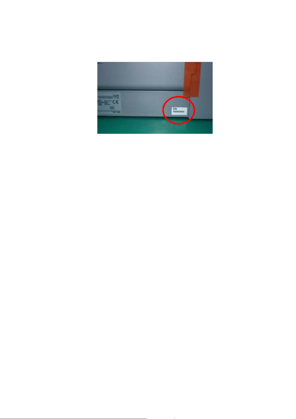
1-5 Serial Number Label Location
On the right side of the backside in the bottom case (close to the rating plate)
Figure1-1 Serial Number Label Location
1 - 5
Page 13

2. LIST OF ERROR DISPLAY / INDICATION
User error messages
Look for the applicable error message and execute the appropriate countermeasures.
Error Codes
As for the causes and countermeasures, only the error codes that are newly incorporated in the unit remedies
unique to the product are included in New Error Codes and Recovery Methods. For the causes and
countermeasures of other error codes, refer to the separate G3/G4 Facsimile Error Code List (Rev. 2).
Service error code output
When service data #1 SSSW SW01 Bit0 is set to “1”, the following service error codes are displayed when
an error occurs.
2-1 User’s error messege
"CARTRIDGE JAMMED"
Printing position correction failed
Cause: Carriage movement prevented by one of the following.
Damaged shaft.
Parts deformed. (Carriage or guide frame)
Insufficient grease.
Solution: Replace the shaft.
Replace the deformed parts.
Apply more grease.
Cause: Bi-directional print displacement correction failed because the carriage motor is
out of step, or some similar reason.
Solution: Replace the carriage motor.
Home position error
Cause1: Tried to stop the carriage unit that has been moving or to move the carriage unit at a pouse by
force.
Solution1: Do not touch the carriage unit other than cartridge replacement position.
Cause2: Foreign body in carriage section.
Solution2: Open flatbed ass’y and remove the foreign body .
Cause3: Loose carriage belt.
Solution3: Replace carriage unit
Cause4: Carriage motor does not work.
Solution4 (1) Switch power OFF/ON.
(2) Replace carriage motor.
Cause5: The position of the carriage cannot be detected (due to smears on the carriage
encoder film or SPCNT board failure).
Solution5: (1) Switch power off/on.
(2) Wipe the carriage encoder film with a cloth soaked with alcohol.
(3) Replace the carriage encoder film.
(4) Replace the SPCNT board.
1 - 6
Page 14

Note:
This error message means the same as service error codes ##338 and ##340. When this error occurs in
this model, it is not treated as a service error, but as a user error, and the error message is displayed.
“COVER OPEN”
Cause: You opened the scanning unit (printer cover) during an operation.
Solution: Close the scanning unit (printer cover).
Cause: Damaged scanner open arm ass’y, damaged scanner sensor arm, or SPCNT board ass’y failure.
Solution: Replace the scanner open arm ass’y, replace the scanner sensor arm, or replace the SPCNT board
ass’y.
“CHECK PRINTER (PRESS [OK])” (##334 - ##336, ##343, ##345, ##346, ##352, ##356 - ##362)
Cause: The carriage unit does not move due to a foreign body in the carriage section.
Solution: Open flatbed ass’y and remove the foreign body. If there is a paper jam, clear the paper jam.
Cause: The printer’s internal unit has malfunctioned.
Solution: Reinstall the BJ cartridge.
Turn the power off and on.
Check the service error code and refer to an appropriate solution.
Cause: The waste ink tank (absorber) is nearly full.
Solution: Replace the waste ink tank (absorber).
Note:
When replacing the waste ink absorber, you need to reset the waste ink volume counter. [Refer to 3-3
Adjustment/Settings (6) Service mode.]
“MEMORY FULL”
Cause: The machine’s memory is full because you tried to copy a very detailed document.
Solution: Divide the document and copy each part separately.
Cause: The machine’s memory is full because it has received too many documents in the memory
receiving mode. (MP780 only)
Solution: Print out any documents, which are stored in memory. Then start the operation again. If the
memory contains any documents yo u d o not need , del et e th em.
“MEMORY CLEARED (PRESS [OK])”
Cause: After receiving data in the memory receiving mode, the power is off due to a service interruption,
etc., and then the image data received in the memory receiving mode is cleared.
Solution: Press [OK] to go back to the standby status.
1 - 7
Page 15

Memo:
Until you press [OK] button, the machine displays this message continuously and you cannot perform any
operations. The memory clear list of the cleared image data is not displayed in this machine. For the
other party information, confirm in the communication management report.
1 - 8
Page 16
2-2 User error code
The error codes that have newly been added starting with the product are identified
by the notation “new” those error codes for which remedies unique to the product are
offered are identified by the notation “UNQ (UNIQUE).”
No. Tx or Rx Definition Remarks
#001 TX
#003 TX/RX
#005 TX/RX
#009 RX
Document has jammed
Document is too long, or page time-over
Initial identification (T0/T1) time-over
Recording paper has jammed or the recording
paper has run out
#011 RX
#012 TX
#018 TX/RX
#021 RX
Polling reception error
The other party has run out of recording paper
Auto dialing transmission error
The other party has rejected the machine
during polling reception
#022 TX
#037 RX
Call fails
Memory has overflowed when receiving
images
#085 TX
Other party does not support ITU-T Color
Faxing
#995 TX/RX
Memory Communication reservation
2-3 Service Call Errors
No. Tx or Rx Definition
##100 TX
##101 TX/RX
##102 TX
##103 RX
##104 TX
##106 RX
##107 RX
##109 TX
cancellation
The number allowed for retransmission of the procedure signal
was exceeded during transmission
The modem speed of the machine does not match that of the
other party
Fallback is not possible
EOL cannot be detected for 5 sec (15 sec if CBT)
RTN or PIN has been received
The procedure signal cannot be received for 6 sec while in wait
The transmitting machine cannot be use fallback
After transmitting DCS, a signal other than DIS, DTC, FTT,
CFR, and CRP was received, exceeding the permitted number
of transmissions of the procedure signal
1 - 9
Page 17

No. Tx or Rx Definition
##111 TX/RX
##114 RX
##200 RX
##201 TX/RX
##204 TX
##220 TX/RX
##224 TX/RX
##226 TX/RX
##229 RX
##232 TX
##237 RX
##238 RX
##261 TX/RX
Memory error
RTN was transmitted
During image reception, a carrier is not detected for 5 sec
DCN was received through a non-normal procedure
Receive DTC without Tx data
System error (e.g., main program may have gone away)
Fault occurred in the communication procedure signal
Stack Pointer Not within RAM Range
The recording system became locked for 1 min
The IC used to control the encoder malfunctioned
The IC used to control the decoder malfunctioned
The unit used to control recording malfunctioned
System error occurred between the modem and system control
board
##280 TX
The number of re-transmissions of the procedure signal has
been exceeded
##281 TX
The number of re-transmissions of the procedure signal has
been exceeded
##282 TX
The number of re-transmissions of the procedure signal has
been exceeded
##283 TX
The number of re-transmissions of the procedure signal has
been exceeded
##284 TX
##285 TX
##286 TX
##287 TX
##288 TX
DCN has been received after transmission of TCF
DCN has been received after transmitting EOP
DCN has been received after transmitting EOM
DCN has been received after transmitting MPS
After transmitting EOP, a signal other than PIN, PIP, MCF,
RTP, or RTN was received
##289 TX
After transmitting EOM, a signal other than PIN,PIP,MCF,
RTP, or RTN was received
##290 TX
After transmitting MPS, a signal other than PIN,PIP,MCF,
RTP, or RTN was received
##332 TX/RX
##333 TX/RX
##334 TX/RX
##335 TX/RX
Printer control DRAM check error
Printer control ROM check error
Printer control EEPROM check error
Data transmission error between the system control section and
printer control section
1 - 10
Page 18

No. Tx or Rx Definition
##336 TX/RX
##337 RX
UNQ ##341 TX/RX
UNQ ##342 TX/RX
UNQ ##343 TX/RX
##345 TX/RX
##346 TX/RX
NEW ##352 RX
NEW ##355 RX A motor to lift up for CD-R print is malfunctioned
NEW ##356 TX/RX ASF cam sensor error
NEW ##357 TX/RX ASF paper feed (AP) position error
NEW ##358 TX/RX USB Host VBUS overcurrent error
NEW ##359 TX/RX Paper feed position error
NEW ##360 TX/RX Paper feed cam sensor error
NEW ##361 TX/RX Valve sensor error
NEW ##362 TX/RX Motor driver malfunctioned error
BJ head abnormal temperature error
BJ head temperature sensor error
Maintenance Jet Waste Ink Tank Full
Cleaning absorption waste ink capacity full
Ink Detection Waste Ink Tank Full
BJ cartridge head cleaning error
Inside temperature error
Printer control EEPROM head information error
##670 TX
In V.8 late start, the V.8 ability was detected in DIS from the
other party and, in response, CI was transmitted; however, the
procedure failed to advance, causing a T1 time-over condition
##671 RX
In V.8 call arrives, the procedure fails to advance to phase 2
after CM detection, causing a T1 time-over condition
##672 TX
In V.34 transmission, the procedure fails to move from phase 2
to phase 3 and later, causing a T1 time-over condition
##673 RX
In V.34 reception, the procedure fails to move from phase 2 to
phase 3 and later, causing a T1 time-over condition
##674 TX
In V.34 transmission, the procedure fails to move from phase 3
or phase 4 to a control channel or later, causing a T1 time-over
condition
##675 RX
In V.34 reception, the procedure fails to move from phase 3 or
phase 4 to a control channel or later, causing a T1 time-over
condition
1 - 11
Page 19

No. Tx/Rx Definition
##750 TX
In ECM transmission, no significant signal can be received
after transmission of PPS-NULL, and the allowed number of
procedure signal re-transmissions was exceeded
##752 TX
In ECM transmission, DCN was received after transmission of
PPS-NULL
##753 TX
In ECM transmission, the allowed number of procedure signal
re-transmissions was exceeded or a T5 time-over (60 sec)
condition occurred after transmission of PPS-NULL
##754 TX
In ECM transmission, the allowed number of procedure signal
re-transmissions was exceeded after transmission of
PPS-NULL
##755 TX
In ECM transmission, no significant signal can be received
after transmission of PPS-MPS, and the allowed number of
procedure signal re-transmissions was exceeded
##757 TX
In ECM transmission, DCN was received after transmission of
PPS-MPS
##758 TX
##759 TX
##760 TX
##762 TX
##763 TX
##764 TX
##765 TX
In ECM transmission, the allowed number of procedure signal
re-transmissions was exceeded or a T5 time-over (60 sec)
condition occurred after transmission of PPS-MPS
In ECM transmission, the allowed number of procedure signal
re-transmissions was exceeded after transmission of PPS-MPS
In ECM transmission, no significant signal can be received
after transmission of PPS-EOM, and the allowed number of
procedure signal re-transmissions was exceeded
In ECM transmission, DCN was received after transmission of
PPS-EOM
In ECM transmission, the allowed number of procedure signal
re-transmissions was exceeded or a T1 time-over (60 sec)
condition occurred after transmission of PPS-EOM
In ECM transmission, the allowed number of procedure signal
re-transmissions was exceeded after transmission of PPS-EOM
In ECM transmission, no significant signal can be received
##767 TX
after transmission of PPS-EOM, and the allowed number of
procedure signal re-transmissions was exceeded
In ECM transmission, DCN was received after transmission of
PPS-EOM
1 - 12
Page 20

No. Tx or Rx Definition
##768 TX
##769 TX
##770 TX
##772 TX
##773 TX
##774 TX
##775 TX
In ECM transmission, the allowed number of procedure signal
re-transmissions was exceeded or a T5 time-over (60 sec)
condition occurred after transmission of PPS-EOM
In ECM transmission, the allowed number of procedure signal
re-transmissions was exceeded after transmission of PPS-EOM
In ECM transmission, no significant signal can be received
after transmission of EOR-NULL, and the allowed number of
procedure signal re-transmissions was exceeded
In ECM transmission, DCN was received after transmission of
EOR-NULL
In ECM transmission, the allowed number of procedure signal
re-transmissions was exceeded or a T5 time-over (60 sec)
condition occurred after transmission of EOR-NULL
In ECM transmission, ERR was received after transmission of
EOR-NULL
In ECM transmission, no significant signal can be received
##777 TX
##778 TX
##779 TX
##780 TX
##782 TX
##783 TX
after transmission of EOR-MPS, and the allowed number of
procedure signal re-transmissions was exceeded
In ECM transmission, DCN was received after transmission of
EOR-MPS
In ECM transmission, the allowed number of procedure signal
e-transmissions was exceeded or a T5 time-over (60 sec)
ondition occurred after transmission of EOR-MPS
In ECM transmission, ERR was received after transmission of
OR-MPS
In ECM transmission, no significant signal can be received
after transmission of EOR-EOM, and the allowed number of
rocedure signal re-transmissions was exceeded
In ECM transmission, DCN was received after transmission of
OR-EOM
In ECM transmission, the allowed number of procedure signal
re-transmissions was exceeded or a T5 time-over (60 sec)
##784 TX
condition occurred after transmission of EOR-EOM
In ECM transmission, ERR was received after transmission of
OR-EOM
1 - 13
Page 21

No. Tx/Rx Definition
##785 TX
In ECM transmission, no significant signal can be received
after transmission of EOR-EOP, and the allowed number of
procedure signal re-transmissions was exceeded
##787 TX
In ECM transmission, DCN was received after transmission of
OR-EOP
##788 TX
In ECM transmission, the allowed number of procedure signal
retransmissions was exceeded or a T5 time-over (60 sec)
condition occurred after transmission of EOR-EOP
##789 TX
In ECM transmission, ERR was received after transmission of
EOR-EOP
##790 RX
In ECM reception, ERR was transmitted after reception of
EOR-Q
##791 TX/RX
During an ECM mode procedure, a signal other than a
significant signal was received
##792 RX
In ECM reception, PPS-NULL between partial pages cannot be
detected
##793 RX
In ECM reception, no effective frame was detected while
signals were received at high speed, and a time-over condition
occurred
2-4 New Error Codes and Recovery Methods
Those error codes that have been added starting with the product and those error codes for
which remedies unique to the product are offered are shown together with causes and
remedies, where applicable.
##341 Maintenance jet waste ink capacity full
Solution: Replace the waste ink absorber as follows in the error occurs:
(1) Select [7] PRINTER TEST in the service mode and select [5] INK ABS CAPA under the [7], then
input “0”.
(2) Check to make sure that no image exist in memory; then, turn off the power, remove the appropriate
parts, and replace the waste ink absorber.
##342 Cleaning absorption waste ink capacity full
Solution: Replace the waste ink absorber as follows in the error occurs:
(1) Select [7] PRINTER TEST in the service mode and select [5] INK ABS CAPA under the [7], then
input “0”.
1 - 14
Page 22

(2) Check to make sure that no image exist in memory; then, turn off the power, remove the appropriate
parts, and replace the waste ink absorber.
##343 Ink detection waste ink capacity full
Solution: Replace the waste ink absorber as follows in the error occurs:
(1) Select [7] PRINTER TEST in the service mode and select [5] INK ABS CAPA under the [7], then
input “0”.
(2) Check to make sure that no image exist in memory; then, turn off the power, remove the appropriate
parts, and replace the waste ink absorber.
##352 Printer control EEPROM head information error
Cause: The EEPROM for printer control is faulty.
Solution: (1) Turn off and then on the power.
(2) Turn off the power, and replace the print head.
(3) Replace the SPCNT board.
NOTE:
In the presence of ##352, the carriage unit will not move to print head replacement position even when the
inner cover is opened. Moreover the carriage will not be locked in position even when the power is turned
off. When replacing the print head, be sure to turn off the power, and draw out the carriage before
replacement.
##355 Lit-up motor for CD-R print malfunctioned
Cause: In performing a CD-R print, the motor to lift up the carriage shaft is malfunctioned.
Solution: (1) Turn off and then on the power.
(2) Check the connection from the SHEET FEED unit to the SPCNT board ass’y (JPM1).
(3) Replace the SHEET FEED ASS’Y.
(4) Replace the SPCNT board.
##356 ASF cam sensor error
Cause: An error occurs at the ASF cam sensor in the ASF (Auto Sheet Feeder) unit.
Solution: (1) To reboot, press [OK] button or turn off and then on the power.
(2) Replace the SHEET FEED ASS’Y.
##357 ASF paper feed (AP) position error
Cause: An error occurs at the AP positioning in the ASF (Auto Sheet Feeder) unit.
Solution: (1) To reboot, press [OK] button or turn off and then on the power.
(2) Replace the SHEET FEED ASS’Y.
(3) Replace the SPCNT board.
1 - 15
Page 23

##358 USB Host VBUS overcurrent error
Cause: Overcurrent is applied to the VBUS signal of USB.
Solution: (1) To reboot, press [OK] button or turn off and then on the power.
(2) Replace the SPCNT board.
##359 Paper feed position error
Cause: An error occurs at the paper feed positioning.
Solution: (1) To reboot, press [OK] button or turn off and then on the power.
(2) Replace the SHEET FEED ASS’Y.
(3) Replace the SPCNT board.
##360 Paper feed cam sensor error
Cause: An error occurs at the paper feed cam sensor.
Solution: (1) To reboot, press [OK] button or turn off and then on the power.
(2) Replace the SHEET FEED ASS’Y
(3)
Replace the SPCNT board.
##361 Valve sensor error
Cause: An error occurs at the valve sensor in the Purge unit.
Solution: (1) To reboot, press [OK] button or turn off and then on the power.
Replace the SPCNT board.
(2)
##362 Motor driver malfunctioned error
Cause: The motor driver is malfunctioned due to heating, etc.
Solution: (1) To reboot, press [OK] button or turn off and then on the power.
(2)
Replace the SPCNT board.
2-5 Wa rnings
Main body (no LCD indications)
Displayed warning Remarks
None None
1 - 16
Page 24

2-6 Troubleshooting by symptom
Symptom Solution Remarks
General
errors
The unit does not power on.
Nothing is displayed.
(1) Check the power cord
connection.
(2) Check the connection between
the SPCNT board (JPSU1) and
power supply unit.
(3) Replace the power supply unit.
(1) Check the connection
between the Operation panel
unit and SPCNT board
(JPANEL1).
(2) Replace the SCANNER
unit.
(3) Replace the SPCNT board.
Part of the LCD panel does
not display anything.
(1) If the test mode can be
used, check for faulty dot in
LCD display.
(2) Check the connection
between the Operation panel
unit and SPCNT board
(JPNL1).
(3) Replace the SCANNER
UNIT.
(4) Replace the SPCNT board
ass’y
.
The keys do not work.
(1) Check the connection
between the SCANNER UNIT
and SPCNT board (JPNL1).
(2) Replace the SCANNER
UNIT.
(3) Replace the SPCNT board.
No sound from the speaker
(MP780 only)
(1) Check the connection of
the speaker and SPCNT board
(JSPK1).
(2) Replace the speaker.
Printing
problems
The paper is not feed
properly.
(The Paper feed motor does
not run.)
(3) Replace the SPCNT board.
(1) Check the connection from
the sheet feed unit to the
SPCNT board assy (JPM1).
(2) Replace the sheet feed unit.
(3) Replace the SPCNT board
ass’y.
1 - 17
Page 25

Printing
problems
The paper is not picked up
from the auto sheet feeder.
Symptom Solution Remarks
(1) Check the foreign matter in
the paper feed section.
(2) Check the connection
SHEET FEED UNIT to the
SPCNT board ass’y (JPM1).
(3) Replace the SHEET FEED
UNIT.
(4) Replace SPCNT board
ass’y.
The carriage motor does not
run.
(1) Check the connection from
the SHEET FEED unit to the
SPCNT board ass’y (JPM1).
(2) Replace the SHEET FEED
unit.
(3) Replace the SPCNT board
ass’y.
Carriage error
(The carriage comes into
contact with the push-on
plates at the left and right
sides, resulting in noise.)
(1) Check if grease adheres to
the carriage encoder film.
(2) Using lint-free paper
impregnated with alcohol,
wipe the carriage encoder film
with care so as not to scratch
the film.
(3) If a lot of grease adheres to
the carriage, replace the
carriage board because grease
might be spread to the sensor
on the carriage board.
(4) Replace the carriage
encoder film.
Printing
Quality
error
• The printer does not at all.
• Printing stops midway.
• Certain colors are not
printed.
(1) Remove the print head and
re-install it.
(2) Carry out nozzle cleaning
on the print head five times
with the cleaning operation,
than visually cheek the test
print for non-discharge of ink
from nozzle. (Fig. 1-2)
(3) Remove and reinstall the
print head.
(4) Replace the appropriate ink
tank.
(5) Replace the print head.
(6) Replace the SPCNT board
ass’y.
(7) Replace the purge unit.
1 - 18
Page 26

Symptom Solution Remarks
Printing
Quality
error
Blotches appear
Blank ink appear
(1) Remove and reinstall the
print head.
(2) Carry out nozzle cleaning
on the print head five times
with the cleaning operation,
than visually cheek the test
print for non-discharge of ink
from nozzle. (Fig. 1-1)
(3) Perform print head
refreshing, and print out
Nozzle check pattern.
Visually check the test print
for non-discharge of ink from
nozzle. (Fig. 1-1)
(4) Replace the appropriate ink
tank.
(5) Replace the print head.
(6) Check the connection of
the carriage ribbon cable and
the SPCNT board.
(JHD1, JHD2)
(7) Replace the carriage unit.
(8) Replace the SPCNT board.
(9) Replace the purge unit.
Scanning
problems
The document is not fed.
(The document feed motor
does not run.)
1) Check the connection from
the document feed motor to
the ADF board ass’y..
(2) Check the connection from
the ADF board ass’y and
SPCNT board ass’y (JADF1).
(3) Replace the document feed
motor.
(4) Replace the ADF board
ass’y.
(5) Replace the SPCNT board.
The document slips against
the rollers. (Evaluation
criteria: Check it visually.
Stretched copy image.)
(1) Cleaning the ADF
section’s parts. See this
Chapter 4. Cleaning Your
Machine
(2) Replace the ADF section's
rollers.
1 - 19
Page 27

Symptom Solution Remarks
Scanning
problems
The
Scanning
Image
Is
Abnormal
The document does not
separate.
Faulty scanner unit's
sensors (The placed
document or
transported document is
not detected.)
Nothing is printed.
1) Check whether the
document feed motor is
driving all the rollers. (Check
for any damaged gears or
foreign matter stuck inside.)
(2) ) Cleaning the Separate
Rollor and RubberSheet. See
Chapter 4. Cleaning your
Machine.
(3) Replace the separation
roller ass’y and Upper guide
ass’y.
1) Check for any faulty
sensors while executing the
copying operation and test
mode.
(2) Check the connection from
Document sensor and
Document edge sensor to the
ADF board.
(3) Check the connection from
the ADF board to the sensor
board sub PCB (JADF1).
(4) Check the connection from
the sensor board (JADF1) and
SPCNT board.
(5) Replace the Document
sensor.
(6) Replace the ADF board
ass’y.
(7) Replace the SPCNT board
ass’y.
(1) Check the connection
between the contact sensor
and SPCNT board (JCCD1).
(2) Replace the SCANNER
unit.
(3) Replace the SPCNT board
ass’y.
1 - 20
Page 28
Symptom Solution Remarks
The
Scanning
Image
Is
Abnormal
Faulty
CD-R
(MP780
only)
Other
The image has vertical
stripes.
The halftone image
contains black dots.
The CD-R Tray is not
recognized.
(As-received failure)
The display appers in
English.
(1) Clean the Document glass.
(2) Check the connection
between the contact sensor
and SPCNT board (JCCD1).
(3) Replace the SCANNER
unit.
(4) Replace the SPCNT board
ass’y.
(1) Clean the Document glass.
(2) Check whether the
document is not skewed.
(3) Check the connection
between the SCANNER unit
and SPCNT board (JCCD1).
(4) Replace the SCANNER
unit.
(5) Replace the SPCNT board
ass’y.
(1) Remove the CD-R Tray,
and place the CD-R Tray
again.
(2) Check the connection
between the CARRIAGE
UNIT and SPCNT board
ASS’Y (JHD1, JHD2).
(3) Replace the CARRIAGE
UNIT.
(4) Replace the SPCNT
BOARD ASS’Y.
Select the settings of
[#8CLEAR]-[ALL] and
[#5TYPE] (Type setting) in
Service Mode, and turn the
power OFF/ON with the
power button (Software
Power: OFF/ON).
Missing dots
Unstable printing Splashed dots
Figure1-2 Defective Pattern (Sample)
1 - 21
Page 29
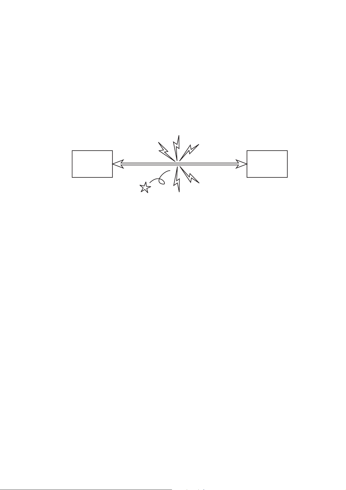
2-7 Processing Communication Problems (MP780 only)
2-7-1 Initial identification of problems
Since the facsimile must transmit picture information, a transmitter, a receiver and telephone lines
are required for this purpose. Transmissions may cause problems if one or more of the there is
poor.
Communication
trouble
FAX FAX
Your
customer's
machine
Figure1-3 Communication Trouble
Communication
companion
machine
1 - 22
Page 30
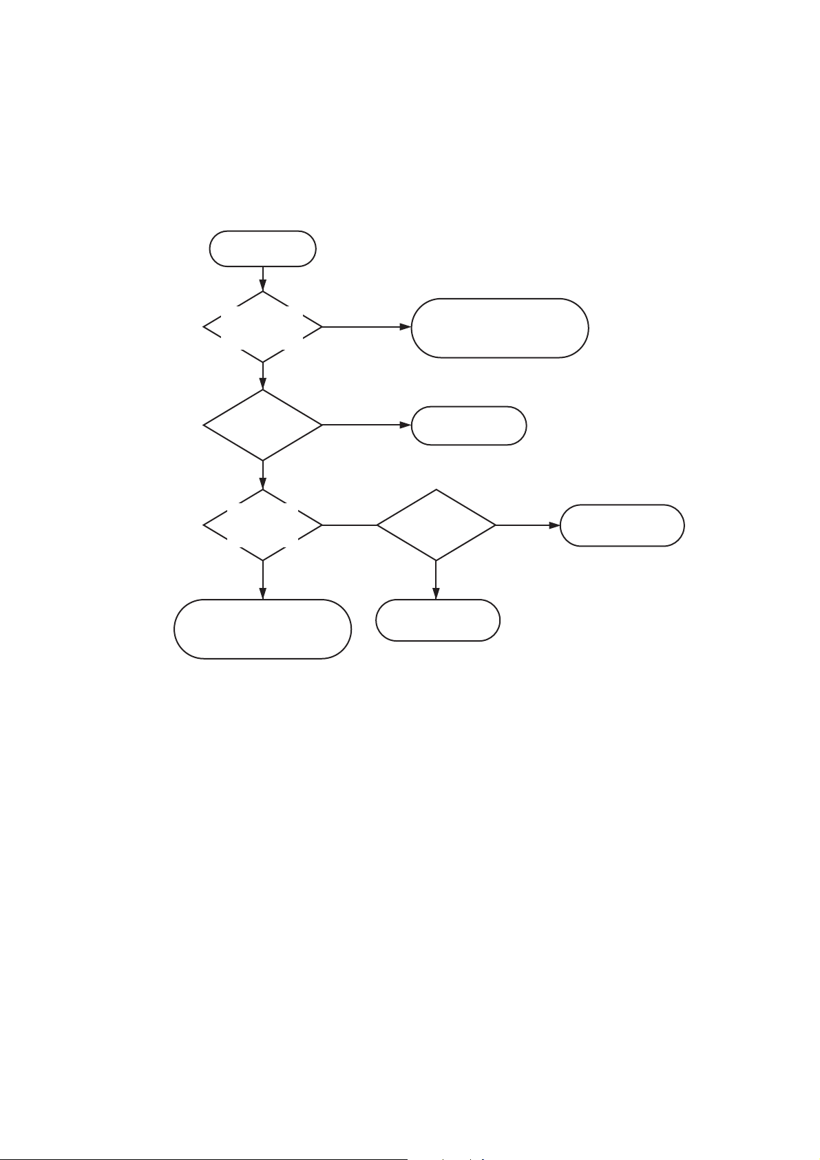
To process communication problems, first of all, it is necessary to narrow down the cause of the problem. Thus,
the procedures appearing below must be checked accordingly.
Start
Does an error
appear on the
display?
NO
Is copying
being done?
OK
Do copying
Is copy
picture OK?
OK
Communication problems
exist. Carry out the procedures
on the next page.
YES
NG
NG
Errors show on the display.
error massage page 1-6
error code page 1-9
General error
Page 1-17
Test print
OK
Scanning problem
Page 1-19
NG
Printing problem
Page 1-17
Figure 1-4 Procedures for Initial Identification of Trouble
1 - 23
Page 31

2-7-2 Procedures for processing communication problems
If the problem proves to be communication trouble, deal with it according to the following procedures.
(1) Study the conditions at the time of trouble as closely as possible. Record or keep the items listed
below.
a) Operations at the time of trouble.
Document number, transmission mode, error occurrence timing call set-up method (auto dialing etc.)
b) Sample of defective picture (When receiving)
c) LCD display at the time of trouble.
d) Communication management report at the time of trouble.
e) User's name, telephone number (to contact), Fax number, model name.
f) User's name, of the other party, telephone number (to contact), Fax number, model name, name of
servicemen in charge.
g) Frequency of trouble and error code (##100 etc.).
h) Condition of the other party's facsimile:
Transmitted/received page number? Automatic or manual?
Error occurred? The receive condition? etc.
NOTE:
When visiting a user with a trouble report, a) can be known by outputting the error protocol data (or
error dump), and g) can be known by outputting the total transaction report (or the system error data
list).
(2) Test communication according to flowchart procedures appearing on the next page.
* Carry out the tests with the actual lines on each item, verify the symptoms and record it.
* In the case of trouble with another manufacturer's facsimile, refer to the flowchart for troubles with
other manufacture's.
(3) Finally, process over by judging systematically all the data.
NOTE:
If the other party's facsimile is that of another manufacturer and there is nothing wrong with your
customer's machine, it is recommended that you ask your customer to contact the facsimile user of
the other party, so that the other party's facsimile is checked by the dealer. "Call the service station"
in the flowchart means that problems may occur with regard to the communication compatibility of
facsimile, consult the matter with the staff in charge at the service station. To quicken the resolving of
the problem, report the information listed in (1) above.
1 - 24
Page 32

2-7-3 Procedures for processing communication problems with Canon facsimile.
The process for carrying out communications at three points as shown in the figure.
Trouble
Start
Transmission
or reception?
Reception
C A
NG
Check A.
Transmission
OK
B C
Chec
NG
k B.
FAX:A
FAX:B
FAX:C
A: Your customer's facsimile
B: Facsimile of other communication party
C: Facsimile for check in the same region. (C should
be the same model of facsimile as A.)
OK
A C C B
NG
Check A. Check B.
OK
NG
OK
Check the
line.
Figure 1-5 Flowchart for Processing Communication Troubles
with Canon Facsimile
1 - 25
Page 33

2-7-4 Procedures for processing communication problems with other manufacturer's facsimiles.
When problems occur with other manufacturer's facsimiles, make the user of the other party's
facsimile call the serviceman in charge. Perform communication at the four points listed in the
figure.
Start
FAX:A
Trouble
FAX:B
Is the group
the same?
(G1/G2/G3)
No
Unable to
receive
Yes
FAX:C FAX:D
Is there the
similar
trouble case?
Yes
Process according
to the case
Transmitter
or receiver?
receiver
OK OK
C A A C
NG
Check A. Check A.
No
A: Your customer's facsimile
B: Facsimile of other communication
party
C: Facsimile for check in the same
region. (C should be the same mode
of facsimile as A.)
D: Other manufacturer's facsimile for
check that is in the same region.
Transmitter
NG
D A
NG
OK
Call the service
station.
OK NG
OK
OK
B D
NG
Check B.
B C C B
NG
D C C D
NG NG
Call the service
station.
OK
OK
Check B.
OK
D B
NG
Check B.
Figure 1-6 Flowchart for Processing Communication Troubles with
other manufacturer’s facsimile
1 - 26
Page 34

3. REPAIR
3-1 Notes on Service Part Replacement (and Disassembling / Reassembling)
Service part Notes on replacement*1
SPCNT BOARD ASS’Y
(MP750: HY7-2931
MP780: HY7-3082)
INK ABSOBER
(HY7-2885/2886/2887/
2888/2889/2890/2891/
2953)
CARRIAGE UNIT
(HY7-2862)
P APER FEED MOT OR
(HY7-2912)
- Before removal of the
SPCNT board ass'y, remove
the power cord, and allow for
approx. 1 minute (for
discharge of capacitor's
accumulated charges), to
prevent damages to the
SPCNT board ass'y.
- Before replacement, check
the waste ink amount (by
service test print or EEPROM
information print).
-SYSTEM DA T A LIST
- The JP2 short plug (for
voltage drop protection) is
half connected. Remove the
plug once, and insert it again
for short-circuiting status.
(MP780 only)
[See Fig1-7]
Apply grease to the sliding
portions.
[See 3-3. Adjustment /
Settings, 3-3-7 Grease
application.]
-The red screws securing the
paper feed motor are allowed
to be loosened. (DO NOT
loosen any other red screws.)
Adjustment / settings Operation check
After replacement:
1.Clear ALL *2
(Initialize the EEPROM.)
2.TYPE setting *2
Power SW OFF/ON
3. Reset the waste ink counter.
4. Service data setting
5. CD-R sensor calibration
[See 3-6 Test mode 3-6-5 CD-R
Calibration]
[See 3-6. Service SW, for details
of 1 to 4]
6. Perform the print head
alignment in the user mode.
- EEPROM information
print
- Service test print
- SYSTEM DATA LIST
- Copy
- Sending and Receiving
(MP780 only)
- Printing via parallel or
USB connection
- Direct printing from a
digital camera
After replacement:
1. Reset the waste ink counter.
[See 3.3. Adjustment / Settings,
3-3-8 Waste ink counter setting]
- EEPROM information
print
1. CD-R sensor calibration
[See 3-6-5. CDR Calibration]
2. Perform the print head
alignment in the user mode.
-Service test print (Confirm
CD-R and automatic print
head alignment sensor
correction.)
1. Adjust the paper feed motor.
[See 3-3. Adjustment / Settings,
3-3-1 Paper feed motor
adjustment.]
1 - 27
Page 35

Service part Notes on replacement*1 Adjustment / settings*2 Operation check
LIFT CAM SHAFT
(HY7-2902)
TIMING SLIT STRIP
FILM
(HY7-2863)
TIMING SLIT DISK
FILM
(HY7-3083)
- Grease application to the
sliding portions
[See 3-3. Adjustment /
Settings, 3-3-7 Grease
application.]
-
Upon contact with the film,
wipe the film with ethanol.
- Confirm no grease is on the
film. (Wipe off any grease
thoroughly with ethanol.)
- Do not bend the film
After replacement:
1. LIFT CAM SHAFT phase
adjustment
See 3-3. Adjustment / Settings,
3-3-3 LIFT CAM SHAFT.]
After replacement:
1. Perform the print head
alignment in the user mode.
Service test print
-
-Service test print
PRINT HEAD
(QY6-0049)
After replacement:
1. Perform the print head
alignment in the user mode.
-Service test print
PAPER EXIT TRAY
UNIT
(HY7-2907)
LEFT COVER
(MP750: HY7-3079
MP780: HY7-2893)
RIGHT COVER
Align the three claws of the
(HY7-2923)
Align the left side of the tray
with the T-part’ angle of
Solenoid Cam Gear to insert
(after removing the tray, the
angle returns to almost
vertical by the force exerted
by the spring). Then pull the
tray open a little (approx. 30 –
60 degrees) and move it
toward the left side to insert
the other side of the shaft (see
the photo in Figure 1-7).
Align the two claws of the
bottom frame with the claws
of the left cover (see the photo
in Figure 1-8).
bottom frame with the claws
of the right cover (see the
photo in Figure 1-9).
*1: General notes:
- Make sure that the flexible cables and wires in the harness are in the proper position and connected correctly.
[See 3-2. Special Notes on Repair Servicing, 3-3-1 Flexible cable and harness wiring, connection, for details.]
- Do not drop the ferrite core, which may cause damage.
- Protect electrical parts from damage due to static electricity.
- Before removing a unit, after removing the power cord, allow the printer to sit for approx. 1 minute (for capacitor dischar ging
to protect the logic board ass'y from damages).
- Do not touch the timing slit strip film and timing slit disk film. No grease or abrasion is allowed.
- Protect the units from soiled with ink.
- Protect the housing from scratches.
- Exercise caution with the red screws, as follows:
i. The red screws of the paper feed motor may be loosened only at replacement of the paper feed motor unit (DO NOT
loosen them in other cases).
ii. DO NOT loosen the red screws on both sides of the main chassis, securing the carriage shaft positioning (they are not
*2: When SPCNT BOARD ASS’Y is replaced, be sure to select the settings of [#8CLEAR]-[ALL] and [#5TYPE] in Service Mode,
adjustable in servicing).
and turn the power OFF/ON with the Power button (Software Power: OFF/ON). DO NOT turn the power OFF/ON by removing
and inserting the power code (Hardware Power: OFF/ON). In this case, data may not be written correctly.
1 - 28
Page 36

Figure1-7 Solenoid Cam Gear
d
r
Y
p
r
n
t
To attach the PAPER EXIT TRA
UNIT, align the tray with the
T-
art of the Solenoid Cam Gea
to insert. Then pull the tray ope
a little and move it toward the lef
side to insert the other side of the
shaft.
The following photos show the left and the right cover claws. Align them for assembling.
Figure1-8 LEFT COVER Figure1-9 RIGHT COVER
Battery
Short plug
As shown in
Figure 1-10,
remove an
connect the
short plug fo
the
short-circuiting
status.
(Open) (Short)
Figure 1-10 SPCNT Short Plug location
(MP780 only)
1 - 29
Page 37

3-2 Special Notes on Repair Servicing
N
N
N
3-2-1 Flexible cable and harness wiring, connection
Be careful of wiring of the flexible cables and harness. Improper wiring or connection may cause
breakage of a line, leading to ignition or emission of smoke.
(1)
(2)
(3)
(4)
(1) Cable guide wiring
CU BOARD - POWER
SUPPLY UNIT
CU BOARD - RELAY
BOARD
CU BOARD
CAMERA DIRECT
BOARD
SPCNT BOARD
Figure 1-11 Flexible cable and harness wiring, connection
RELAY BOARD A
SPCNT BOARD
(JPSU1) POWER SUPPLY
UNIT
SPCNT BOARD
(JCCD1)SCANNER UNIT
Figure 1-12 Cable Guide wiring
1 - 30
Page 38

(2) SPCNT BOARD ASS’Y wiring
SPCNT BOARD (JPSU1) POWER SUPPLY UNIT
SPCNT BOARD (JHD1/JHD2) - CARRIAGE UNIT
SPCNT BOARD
(JADF1) ADF BOARD ASS’Y
SPCNT BOARD (JSOL1) SOLENOID
SPCNT BOARD (JPSC1)CAMERA DIRECT BOARD
SPCNT BOARD (JSPK1) SPEAKER UNIT
SPCNT BOARD
(JEXT1) RELEY BOARD ASS’Y
SPCNT BOARD
(JPM1) CARRIAGE/
LF/AP/PAPER FEED
MOTOR
SPCNT BOARD
(JMC1) PURGE UNIT
SPCNT BOARD
(JINK1) PLATEN UNIT
SPCNT BOARD
Figure 1-13 SPCNT BOARD ASS’Y wiring
(JVLV1) PURGE UNIT
1 - 31
Page 39

N
N
N
(3) RELAY BOARD ASS’Y wiring
RELAY BOARD (JSNS2) LF Encoder / PE Sensor
POWER SUPPLY (CN3) -
CU BOARD
SPCNT BOARD (JEXT1) RELAY BOARD (JREL)
(4) POWER SUPPLY UNIT wiring
Figure 1-14 RELAY BOARD ASS’Y wiring
POWER SUPPLY (CN4) SPCNT BOARD (JPSU1)
POWER SUPPLY (CN3) -
CU BOARD
RELAY BOARD
(JSNS1) -
PF Encoder /
PF PE Encoder /
AP Encoder
RELAY BOARD
(JNCU) -
CU BOARD
REGULATOR POWER SUPPLY
(CN6)
Figure 1-15 POWER SUPPLY UNIT wiring
1 - 32
Page 40

3-3 Adjustment / Settings
3-3-1 PAPER FEED MOTOR Adjustment
Perform the following adjustments when the paper feed motor unit is replaced:
1) When attaching the motor, fasten the screws so that the belt is properly stretched (in the
direction indicated by the blue arrow in the figure below).
2) After replacement, be sure to perform the service test print, and confirm that no strange noise or
faulty print operation (due to dislocation of the belt or gear, or out-of-phase motor, etc.) occurs.
Red screws securing the
PAPER FEED MOTOR
Figure 1-16 PAPER FEED MOTOR Adjustment
Note:
The red screws securing the paper feed motor may be loosened only at replacement of the paper
feed motor unit. DO NOT loosen them in other cases.
3-3-2 CARRIAGE SHAFT Gear Adjustment
In installing a carriage shaft, the gear phase should be adjusted.
(1) Insert the metallic pin shown below to the hole in the PURGE UNIT (see the photo (a) below) (until
it reaches the end).
[Metallic pin]
- Diameter: 2.0 mm or less, and Length: 20.0 mm or more
(Use “CARRIAGE SHAFT L SPRING: HY7-2867”, or an unbended clip can be used in place of the
pin.)
(2) With the metallic pin inserted, turn the LIFT GEAR 2 clockwise (in the direction indicated by the
arrow in the photo (b) below) until it reaches the end. (Stop when it cannot turn farther any more.)
Under the conditions above, confirm that the ASF ARM LOCK LEVER is located upward (see Photo
(c)) and the capping section is located at the capping position (see Photo (d)).
2.0mm or less 20.0mm or more
1 - 33
Page 41

p
R
R
m
(a) (b)
CARRIAGE SHAFT
LEFT GEAR 2
(c) ASF ARM LOCK LEVER (d) CAPPING
(3) Install the LEFT GEAR 1 by aligning it on the cutout of the CR SHAFT CAM R.
Align the two parts
so that both surfaces
shown at the top are
horizontal.
Or, adjust so that the
art of the C
SHAFT CAM
shown at the botto
is just at the bottom.
LEFT GEAR 1
Figure 1-17 CARRIAGE SHAFT gear adjustment
1 - 34
Page 42

3-3-3 Positioning in LIFT CAM SHAFT ASS’Y adjustment
(1) Remove the PRESSURE ROLLER SPRING from the hook of the chassis, and apply it to the gash
of the LIFT CAM SHAFT ASS’Y.
Figure 1-18 Positioning in LIFT CAM SHAFT ASS’Y adjustment 1
PRESSURE ROLLER SPRING
LIFT CAM SHAFT ASS’Y
(2) Turn the gear of the LIFT CAM SHAFT ASS’Y in the direction indicated by the arrow “a” in the
photo (clockwise) until it reaches the end.
(3) Turn the gear of the LIFT CAM SHAFT ASS’Y in the direction indicated by the arrow “b” in the
photo below (counterclockwise) until it reaches the end.
a
b
Figure1-19 Positioning in LIFT CAM SHAFT ASS’Y adjustment 2
1 - 35
Page 43

3-3-4 SOLENOID CAM location
(1) Install the spring so that the Short end of the spring is at the top and the Long end of the spring is at
the bottom. (The part has a protection against reverse installation.)
SOLENOID
CAM
SPRING
Short
SOLENOID
Long
Figure 1-20 SOLENOID CAM spring location
3-3-5 CARRIAGE SHAFT CLIP location
(1) Adjust the ellipse area of CARRIAGE SHAFT CLIP and the edge of TIMING SLIT STRIP FILM
Red screws
Ellipse Area of
CARRIAGE SHAFT
CLIP
Figure 1-21 CARRIAGE SHAFT CLIP location
1 - 36
Page 44

3-3-6 Applying White Sheet
(1) Rib bumps are provided in the vertical and the horizontal directions (locatio n marks) on the back
side of the document cover. Temporally attach the white sheet to the top right corner (no mark),
which is the intersection point of the lines that link the marks.
(2) Attach the whole part of the white sheet, by align ing the top edge and the right edge of the white
sheet on the lines that link the location marks in the top side and the right side on the back side of
the document cover.
(2)
(1)
White sheet
(3) Confirm the location to apply the white sheet. For the confirmation, lift up the document cover
just a little, and look into to visually confirm that the edges of the white sheet are not placed on
the scanner top cover (molded part).
OK Example: The edges of the white sheet are not located on the scanner top cover.
(2)
Rib bumps (location marks)
Figure 1-22 Applying white Sheet
White Sheet Corners
Figure 1-23 Location confirmation to apply the white sheet (the rear side and the right side)
(OK example)
1 - 37
Page 45

NG Example: The edges of the white sheet are located on the scanner top cover.
Figure 1-24 Location confirmation to apply the white sheet (the rear side and the right side)
(NG example)
1 - 38
Page 46

3-3-7 Grease application
(2)
(2)
(3) (4)
(1)
(9)
(10)
(8)
Figure 1-25 Grease application1
1 - 39
Page 47

(5)
(7)
(6)
Figure 1-26 Grease application2
Part name Where to apply grease / oil Grease / oil name
Chassis
LIFT CAM SHAFT
CARRIAGE SHAFT 8 CARRAGE and CARRIAGE SHAFT
CARRIAGE SHAFT
SPRING L
CARRIAGE SHAFT
SPRING R
Note: 1 drop = 9 to 18 mg
1 Entire surface the CARRIAGE
SLIDER contacts
2 CARRIAGE SHAFT sliding portion FLOIL KG107A
3 CARRIAGE SHAFT CAM L sliding
portion
4 CARRIAGE SHAFT CAM R sliding
portion
5 LIFT CAM SHAFT sliding portion FLOIL KG107A
6 SPRING sliding portion (4 points) FLOIL KG107A
7 PRESSURE ROLLER ASS’Y sliding
portion (4 points)
sliding portion
9 CARRIAGE SHAFT sliding portion
(over the area more than 2/3 from the
top end of the spring)
10 CARRIAGE SHAFT sliding portion
(over the area more than 2/3 from the
top end of the spring)
FLOIL KG107A
MOLYKOTE
HP300
MOLYKOTE
HP300
FLOIL KG107A
FLOIL KG107A
FLOIL KG107A
FLOIL KG107A
Grease / oil
amount
3 drops
4 drops
2 drops
1 drop
1 drop
1 drop
x 4 points
1 drop
x 4 points
200 to 400mg
1 drop
1 drop
1 - 40
Page 48

3-3-8 Waste ink counter setting
When the SPCNT board ass'y is replaced, check the amount of the waste ink capacity before the
replacement. After the replacement, register the amount of the waste ink capacity on the new
SPCNT board ass’y that has been replaced.
To check the waste ink capacity, print out the EEPROM information print.
To register the waste ink capacity, select [7] PRINTER – [5] INK ABS CAPA in the service mode,
and input a value between 0 – 100 (%) with the numeric keys.
3-4 User data flow
Press the [ENLARGE/REDUCE] button PRESET RATIO 400% MAX. 400% MAX.
ZOOM 25 ~ 400 %
(USA) (EUROPE)
212% 4"x 6" -> LTR 141% A5 -> A4
170% 5"x 7" -> LTR 115% B5 -> A4
* 100% * 100%
95% A4 -> LTR 86% A4 -> B5
25% MIN. 70% A4 -> A5
25% MIN.
FIT-TO-PAGE
Press the [PAPER] button SIZE A4 * A4
TYPE * PLAIN CARD
Press the [DENSITY] button 9 STEP (- LIGHT + DARK)
Press the [IMAGE QUALITY] button NORMAL
FINE (PHOTO)
FAST
(USA) (EUROPE)
* LTR LTR
LGL LGL
4"x 6" B5
5"x 7" A5
CARD 4"x 6"
5"x 7"
GLOSSY
HIGH RES.
TRANS.
PHOTO PRO
PHOTO PLUS
OTHER
Figure 1-27 Use data flow (1/5)
1 - 41
Page 49

[COPY] button (*a)
[MENU]
1. SPECIAL COPY BORDERLESS COPY S IZE * A4
TYPE GLOSSY
IMAGE REPEAT MANUAL VERTICAL 4
HORIZONAL 4
(MP780 only) * AUTO
2. FAX SETTING (*b)
(USA) (EUROPA)
1. RECIEVE MODE * FAX/TEL AUTO SW FAX/TEL AUTO SW
FAX ONLY MODE * FAX ONLY MODE
DRPD DRPD
MANUAL MODE MANUAL MODE
ANS. MACHINE MODE ANS. MACHINE MODE
2. MEMORY REFERENCE
3. REPORTS / LISTS ACTIVITY REPORT
SPEED DIAL LIST
USER DATA LIST
DOC. MEMORY LIST
LTR
4"x 6"
5"x 7"
CARD
*PHOTO PRO
PHOTO PLUS
OTHER
3
*2
1
3
*2
1
4. TEL# REGISTRATION
MEMO:
(*a)(*b): Press the [FAX] button and then the [MENU] button to display this setting at the beginning.
Figure 1-28 Use data flow (2/5)
1 - 42
Page 50

Y
Y
Y
Y
K
Y
5. USER SETTINGS DATE / TIME S ETTING
DATE SETUP YYYY/DD/MM YYYY/DD/MM
UNIT TEL NUMBER
UNIT NAME
TX TERMINAL ID * TTI POSITION * ON
OFFHOOK ALARM * ON
VOLUME CONTROL CALLING VOLUME 3
RX CALL LEVEL STANDARD
TEL LINE TYPE ROTARY PULSE
ACTIVI TY REPORT * AUTO PRINT ON
(USA) (EUROPE)
* MM/DD/YYY
DD/MM/YYY
(USA) (EUROPE)
TEL NUMBER MAR
OFF
LINE MONITOR VOL. 3
*HIGH
*TOUCH TONE
AUTO PRINT OFF
MM/DD/YYY
* DD/MM/YYY
OFF
*2
1
*2
1
0
6. TX SETTINGS ECM TX * ON
OFF
(EUROPE)
UN/LOCK PHONE LOCK PHONE * ON
PASSWORD OFF
PAUSE TIME * 2 SEC (1-15 SEC)
AUTO REDIAL * ON
OFF
TX START SPEED 14400 bps
9600 bps
7200 bps
4800 bps
2400 bps
* 33600 bps
COLOR DIRECT TX * OFF
ON
TX REPORT OUTPUT NO
* PRINT ERROR ONL
OUTPUT YES
Figure 1-29 Use data flow (3/5)
1 - 43
Page 51

K
7. RX SETTINGS ECM RX * ON
FAX/TEL AUTO SW RING START TIME * 8 SEC (0~30)
DRPD: SELECT FAX NORMAL RING
INCOMING RING * OFF
MAN/SUTO SWITCH * OFF
REMOTE RX * ON
RX REDUCTION * ON
RX START SPEED 14400 bps
RX REPORT * OUTPUT NO
3. MAINTENANCE NOZZLE CHEC
CLEANING
HEAD REFRESHING
ALIGN PRINT HEAD
AUTO HEAD ALIGN
ROLLER CLEANING
BOTTOM CLEANING
CALIBRATION
OFF
(USA)
F/T RING TIME * 15 SEC (10~45)
(EUROPE)
* 22 SEC (10~60)
F/T SWITCH ACTION * RECEIVE
DISCONNECT
DOUBLE RING
SHORT-SHORT-LONG
SHORT-LONG-SHORT
OTHER RING TYPE
ON
ON
OFF
OFF
9600 bps
7200 bps
4800 bps
2400 bps
* 33600 bps
PRONT ERROR ONLY
OUTPUT YES
Figure 1-30 Use data flow (4/5)
1 - 44
Page 52

K
4. SYSTEM SETTINGS QUIET PRINTING * OFF
ON
EXTENSION AMOUNT * SMALL
LARGE
AUDIBLE TONES KEYPAD VOLUME 0
ALARM VOLUME 0
DISPLAY LANGUAGE * ENGLISH
FRENCH
SPANISH
PORTUGUESE
(EUROPE)
COUNTRY SELECT UK BELGIUM
GERMANY SWITZERLAND
FRANCE PORTUGAL
ITALY IRELAND
SPAIN GREECE
HOLLAND LUXEMBOURG
DENMAR
NORWAY CZECH
SWEDEN RUSSIA
FINLAND SLOVENIA
AUSTRIA SOUTHAFRICA
SUMMER TIME OFF
*ON
1
*2
3
1
*2
3
HUNGARY
OTHERS
POWER SAVE TIMER 15 MINUTES
TWO-SIDED COPY * REAR PG. SAME DIR
THICK PAPER * OFF
AUTO FEED SWITCH * OFF
* 1 HOUR
4 HOURS
8 HOURS
ROTATE REAR PAGE
ON
ON
Figure 1-31 Use data flow (5/5)
1 - 45
Page 53

3-5. SERVICE SWITCHES
3-5-1 Hardware Switches
There is no service hardware switch on the Circuit board.
3-5-2 Service Data Setting
Service data can be checked and changed with items on display menus. The effective
SSSWs/ parameters and their default values in this machine are shown in Service menut
in this chapter. Detailed description of each SSSW/parameter is not given in this manual
except the new SSSWs/parameters added to this model. See G3 Facsimile SERVICE
DATA HANDBOOK (Rev. 1) (supplied separately) for details of them. The new switches
for this model are described in 5.6 New SSSWs/Parameters Added to this Model.
#1 SSSW (Service soft switch settings)
These setting items are for basic fax service functions such as error management, echo
countermeasures, and communication trouble countermeasures.
#2 MENU (MENU switch settings)
These setting items are for functions required during installation, such as NL equalizer
and transmission levels.
#3 NUMERIC Param. (NUMERIC parameter settings)
These setting items are for inputting numeric parameters such as the various conditions
for the FAX/TEL switching function.
#4 NCU (NCU settings)
These setting items are for telephone network control functions such as the selection
signal transmission conditions and the detection conditions, for the control signals sent
from the exchange.
#5 TYPE (TYPE setting)
The type setting makes the service data conform to a specific country communications
standards. There is only one setting item in this block.
#6 GENESIS (UHQ function setting)
These setting items are for scanned image processing such as edge enhancement and error
diffusion processing.
#7 PRINTER (PRINTER function settings)
These setting items are for basic printer service functions such as the reception picture
reduction conditions. Also there is an item for resetting the printer section without
switching the power off-on.
#8 CLEAR (Data initialization mode)
Various data are initialized by selecting one of these setting items. There is a setting item
for checking/inputting the total number of pages printed and total number of pages
scanned by this machine.
#9 ROM (ROM management)
ROM data such as the version number and checksum are displayed.
1 - 46
Page 54

3-5-3 Service Data Registration / Setting Method
Service data can be registered/set by the following operations:
100% LTR NORMAL
PLAIN
(1) User data mode selection
Press the Menu key.
1.SPECIAL COPY
BORDERLESS COPY
(2) Sevice data mode selection
Press the SCAN, COPY, and then SCAN key.
SERVICE MODE
#1 SSSW
(3) Menu item selection
Select the menu item by pressing the key.
SERVICE MODE
#3 NUMERIC Param.
Standby
Press the OK key.
#3 NUMERIC Param.
01: 0
(4) Data registration
Input the data and press the OK key.
Press the Stop/Reset key to return to standby.
Figure 1-32 Service Data Setting Method
1 - 47
Page 55

3-5-4 Service Data Flowchart
Service Data
#1 SSSW
(Service soft switch setting)
#+No.
Caution:
The switches marked “-” are not used. Do not change their settings.
Bit
SW01
SW02
SW03
SW04
SW05
SW06
SW07
SW08
SW09
SW10
SW11
SW12
SW13
SW14
SW15
SW16
SW17
SW18
SW19
SW20
SW21
SW22
SW23
SW24
SW25
SW26
SW27
SW28
SW29
SW30
SW50
76543210
–––1––00
–––––––0
0000––0–
10–000––
–––00–––
–––0–00–
––––––––
––––––––
––––––00
––––––––
––––––––
0–000010
––––––––
––––––––
–0––––––
––––––––
––––––––
––––––00
––––––––
––––––––
––––––––
––––––––
––––––––
––––––––
––––––00
00––0––0
––––––––
––000000
––––––0–
––––––––
SW31 to SW50
Figure 1-33 Service Data (1/6)
Error management (MP780 only)
NETWORK connection condition settings/
memory clear list setting (MP780 only)
Echo solution setting (MP780 only)
Communication trouble
solution settings (MP780 only)
Standard function (DIS signal)
setting (MP780 only)
Scan condition settings
Not used
Not used
Communications result display
function settings (MP780 only)
Not used
Not used
Page timer settings
Not used
Not used
Dial-in FAX/TEL switching function setting (MP780 only)
Not used
Not used
Communication trouble solutions settings (2) (MP780 only)
Not used
Not used
Not used
Not used
Not used
Not used
Report display function settings (MP780 only)
Transmission function settings (MP780 only)
Not used
V.8/V.34 protocol settings (MP780 only)
Flash ROM version up
Not used
Not used
1 - 48
Page 56

#2 MENU
(Menu switch settings)
(MP780 only)
01:
02:
03:
04:
05:
06:
07:
08:
ON
OFF
DIAL
SERVICEMAN
OFF
10 (-10dBm)
(8~15)
3429 (baud)
3200
3000
2800
2743
2400
Not used
Not used
Not used
Not used
NL equalizer setting
Line monitor setting
Transmission level setting
V.34 Baud rate
Caution:
09:
33.6
V.34 Transmission speed
(2.4 kbps - 33.6 kbps)
10:
50 Hz
25 Hz
17 Hz
Items 11 to 20
Not used
20:
Figures in boldface indicate the default setting.
Figure 1-34 Service Data (2/6)
No.01 to 04, 10 to 20 are not used. Do not change their settings.
1 - 49
Page 57

#3 NUMERICParam.
(Numeric parameter settings)
Default Range
0
01:
10 (10%)
02:
15 (15 lines)
03:
12 (12 times)
04:
4
05:
4
06:
350
07:
0
08:
6 (6 digits)
09:
5500 (55 seconds)
10:
3500 (35 seconds)
11:
0
12:
1300
13:
0
14:
120 (1200 ms)
15:
4 (4 seconds)
16:
100 (1000 ms)
17:
0 (0 ms)
18:
200 (2000 ms)
19:
100 (1000 ms)
20:
0 (0ms)
21:
200 (2000 ms)
22:
44
23:
15
24:
60 (600 ms)
25:
44
26:
0
27:
(MP780 only)
(1~ 99)
(2~ 99)
(1~ 99)
(1~ 20)
(0~ 9999)
(0~9999)
(0~ 999)
(0~ 9)
(0~ 999)
999)
(0~
(0~ 999)
(0~ 999)
(0~ 999)
(0~ 999)
(Do not change)
(0~ 20)
(0~ 999)
(Do not change)
Not used
RTN signal transmission condition (1)
RTN signal transmission condition (2)
RTN signal transmission condition (3)
Not used
Not used
Not used
Not used
The number of digits in telephone number
compared against TSI signal to be matched
for restricted receiving function
Line connection detection time (T0 timer)
T1 Timer (Rx)
Not used
Not used
Not used
Hooking detection time
Pseudo RBT transmission from CML on time
until start
Pseudo RBT signal pattern: On time
Pseudo RBT signal pattern: off time (short)
Pseudo RBT signal pattern: off time (long)
Pseudo ring pattern: On time setting
Pseudo ring pattern: Off time (short)
Pseudo ring pattern: Off time (long)
FAX/TEL switching function signal detection level
Pseudo-RBT signal transmission level
Answering machine connection function
signal detection time
Answering machine connection no-sound detection level
Not used
Figure 1-35 Service Data (3/6)
Caution:
No. 01, 05 to 08, 012 to 14, 27 to 30 are not used. Do not change their settings.
The relationship between the settings and the detection levels is as follows:
Parameter 24
0:
Not used, 1: Not used, 2: Not used, 3: Not used, 4: Not used
5: -8 dBm, 6: -9 dBm, 7:-10 dBm, 8:-11 dBm, 9:-12 dBm, 10:-13 dBm, 11:-14 dBm,
12:-15 dBm, 13:-16 dBm, 14:-17 dBm, 15:-18 dBm, 16:-19 dBm, 17:-20 dBm, 18:-21 dBm,
19:-22 dBm, 20:-23 dBm
1 - 50
Page 58

#4 NCU 1.TONE/PULSE
(NCU settings)
(MP780 only)
2.DIAL TONE
3.2nd DIAL TONE
4.BUSY TONE 0
5.BUSY TONE 1
6.REORDER TONE
7.MULTI
8.AUTO RX
9.CNG DETECT
10.SPECIAL
11.RKEY
12.PBX DIAL TONE
13.PBX BUSY TONE
#5 TYPE
(Type setting)
CYGNUS-1
CYGNUS-2
U.S.A.
EUROPE
U. K.
SWEDEN
SWISS
AUSTRIA
DENMARK
NORWAY
HOLLAND
BELGIUM
AUSTRALIA
FINLAND
N. Z.
ITALY
SPAIN
PORTUGAL
IRELAND
HONG KONG
HONG KONG
MALAYSIA
HUNGARY
SAF
KOREA
CHINA
GERMAN
FRANCE
SINGAPORE
CZECH
SLOVENIA
CANADA
JAPAN
RUSSIA
ASIA
POLAND
EUROPE2
STANDARD
Caution:
#4 NCU (NCU settings)
The values of these items are all set to match a specific nation’s communications standards by
the #5 TYPE setting. Do not change these setting.
#5 TYPE (TYPE Setting)
For the machine type settings, select according to the products as follows:
CYGNUS-1: MP750
CYGNUS-2: MP780
Figure 1-36 Service Data (4/6)
1 - 51
Page 59

#6 GENESIS (UHQ)
(Genesis function settings)
#7 PRINTER
(Printer function settings)
1.Bit SW
2.SLICE
3.GAMMA
#1 SSSW
Bit
SW01
SW06
SW20
#2 NUMERIC Param
#3 PRINT COUNT
#4 PRINTER RESET
76543210
––––––––
SW02~05:
–––––100
SW07~20:
Not used
Not used
01: 18 (mm)
02: 0
03: 0
04: 0
05: 5 (mm)
Item 06~30:
30:
XXX/YYY
Yes=(-)
No=(+)
Not used
Reduction settings
Not used
Not used
Not used
Leading edge margin
Trailing edge margin (Black printing)
Not used
Print counter check
Printer section reset function
#5 INK ABS CAPA
#6 CDR ADJUST
SUCTION
[0]:
CDR X SET
1
]:
CDR Y SET
[
Wasteinkcapacitycheck/entry
Figure 1-37 Service Data (5/6)
Caution: #6 GENESIS (UHQ function settings)
Tampering with this setting may cause the scanned image quality to deteriorate.
Do not change these settings.
Memo:
#7 PRINTER (Printer function settings)
1. At #5 INK ABS CAPA, you can check or register the capacity of waste ink ejected during the
cleaning operation. For the waste ink capacity registration, register a value between 0 – 100
(%) with the numeric keys.
The absorption amount of the waste ink absorber is set based upon the amount that the BJ
cartridge has ejected.
The settings of the waste ink capacity are stored in EEPROM of SPCNT BOARD.
When replacing the SPCNT BOARD, check the waste ink capacity before the replacement,
and register the waste ink capacity at the new SPCNT BOARD after the replacement.
2. At #6 CDR ADJUST (CD-R Print writing position adjustment), you can adjust the writing
position in X and Y directions within the following range.
+/-0.0mm, +/-0.1mm, +/-0.2mm, +/-0.4mm, +/-0.6mm, +/-0.8mm, +/-1.0mm
You can also perform this adjustment from “CD-LabelPrint” or “Easy-PhotoPrint”.
1 - 52
Page 60

#8 CLEAR
(Data initialization mode
settings)
#9 ROM
(ROM management)
#10 CS SET
#11 DATE / TIME
TEL
USER SW
SERVICE SW
NCU
SERVICE DATA
REPORT
COUNTER
ALL
MAIN:V0.20
040806 0000 FA00
USB :00.00
CPU :DD-01-01-QUAD
981111 0000 FFFF
1.DISPLAY
2.SETTING
Dialling data initialization
User data and service data #1 to #3
initialization
User data and service data #1 to #3 and
#6 to #7 initialization
#4 NCU setting data initialization
Data on system dump list initialization
Data on activity report initialization
Total number of pages printed/scanned
All user data, service data, activity
management data, and image data
initialization (except COUNTER)
Version No. and Checksum display
Not used
Date and time display
Date and time setting
SERVICE REPORT
TEST MODE
1.SERVICE & SYSTEM
2.SERVICE DATA
3.SYSTEM DUNP
Figure 1-38 Service Data (6/6)
Caution:
If USER SW of #8 CLEAR is selected, communication management data of user data is not deleted.
However, if TEL or SERVICE SW is selected, the communication management data of user data is
deleted.
If ALL of #8 CLEAR is performed, be sure to set #5 TYPE and turn the power OFF/ON with the
Power button (Software Power: OFF/ON). DO NOT turn the power OFF/ON by removing and
inserting the power code (Hardware Power: OFF/ON). In this case, data may not be written
correctly.
Memo:
The date/time settings at #11 DATE/TIME is equivalent to the settings at [FAX SETTINGS] – [USER
SETTINGS] – [DATE&TIME]. Neither has priority.
1 - 53
Page 61

3-5-5 Explanation of service data
a) SSSW (Service Soft Switch settings)
The items registered and set by each of these switches comprise 8-bit switches. The figure below shows
which numbers are assigned to which bits. Each bit has a value of either 0 or 1.
SW01
Bit 7
Bit 6
Bit 5
Bit 4
00000000
Bit 3
Bit 2
Bit 1
Bit 0
Figure 1-39
See the chart in the service data shown in this Chapter, 5.2.3 Service data setting to see effective
bits and their default values. The meanings (functions) of the bits are not described in this manual
except the new switches added to this model. See the G3 Facsimile Service Data Handbook
(supplied separately) for details of the switches.
Below are examples s howing how to read bit switch tables.
Indicates that the
setting is "1".
Function
Bit 1 0
Service error code
0
Error dump list
1
Not used
2
Not used
3
##300 series service error code
4
Not used
5
Not used
6
Not used
7
Figure 1-40 How to Read Bit Switch Tables
Bit Switch Display
Output
Output
Output
Not Output
Not Output
Not Output
Indicates that the
setting is "0".
Figures in boldface
are default settings.
1 - 54
Page 62

3-5-6 New SSSWs/parameters added to this model
#1 SSSW (service soft switch setting)
SW01 (service soft switch 01: error management)
Bit Function 1 0
0 Service error code Output Not output
1 Error dump list Output Not output
2 Not used
3 Not used
4 (New) ##300 series service error code Output Not output
5 Not used
6 Not used
7 Not used
[Bit 4]
Even when Bit0 is set to "Not output", you can select whether or not to output ##300 series Service
Error Codes, caused by hardware malfunction.
When "Output" is selected, ##300 series Service Error Codes are displayed and in reports.
When "Not Output" is selected, no Service Error Codes are displayed.
#1 SSSW (service soft switch setting)
SW15 (service soft switch 15: Dial-in FAX/TEL switching function setting)
Bit Function 1 0
0 Not used
1 Not used
2 Not used
3 Not used
4 Not used
5 Not used
6 (New) Detect continuous signal at Yes No
FAX/TEL switching
7 Not used
[Bit 6]
You may enable or disable detection of ROT continuous signal for FAX/TEL switching.
Normally, only ROT intermittent signals are detected for FAX/TEL switching. If you need to
detect both in view of exchange specifications, select to enable detection.
1 - 55
Page 63

#1 SSSW (service soft switch setting)
SW18 bit Communication trouble solutions settings
Bit Function 1 0
0 Carrier break detection between
DCS and TCF
1 Waiting time for carrier break
2 Not used
3 Not used
4 Not used
5 Not used
6 Not used
7 Not used
[Bit 0]
Enable the carrier break detection between DCS and TCF.
[Bit 1]
Switch the waiting time for carrier break detection between DCS and TCF.
detection between DCS and TCF
(Valid only when bit0 of SW18 is 1)
Yes No
SW26 (service soft switch 26: Transmission function setting)
600[ms] 300[ms]
Bit Function 1 0
0 Compulsory direct transmission Set Not set
1 Not used
2 Not used
3 (New) Prohibit broadcast Yes No
4 Not used
5 Not used
6 When STOP key is pressed Only cancel Cancel all
during a sequential broadcasting communication communication
7 Error transmission report when Not output Output
transmission is stopped
[Bit 3]
You may disable selection of multiple addresses to prevent broadcasting by mistake (on the part of
the user); however, this setting will not affect broadcasting by group dialing.
1 - 56
Page 64

SW28 (service soft switch 28: V.8/V.34 protocol settings)
Bit Function 1 0
0 (New) Caller V.8 protocol NO YES
1 (New) Called party V.8 protocol NO YES
2 (New) Caller V.8 protocol late start NO YES
3 (New) Called party V.8 protocol late start NO YES
4 (New) V.34 reception fallback Prohibited Not prohibited
5 (New) V.34 transmission fallback Prohibited Not prohibited
6 Not used
7 Not used
[Bit 0]
Select whether to use the V.8 protocol when calling. If N O i s selected, t he V. 8 pr ot ocol is inhibited
at calling and the V.21 protocol is used.
[Bit 1]
Select whether to use the V.8 protocol when called. If NO is selected, the V8 protocol is inhibited
when called and the V.21 protocol is used.
[Bit 2]
If ANSam signal is not received during transmission (mainly manual transmission), select whether
to use the V.8 protocol when the other fax machine declares the V.8 protocol in DIS signal. If NO
is selected, the CI signal is not transmitted and the V.8 protocol is not used even if the DIS that
specifies the V.8 protocol is received.
[Bit 3]
Select whether to declare the V.8 protocol in DIS signal for reception (mainly caller manual
transmission). If NO is selected, the V.8 protocol cannot be used because it is not declared in DIS
signal.
[Bit 4]
Select whether the receiver falls back during V.34 reception. If OFF is selected, the receiver does
not fall back.
[Bit 5]
Select whether the transmitter falls back during V.34 transit. If OFF is selected, the transmitter does not
fall back.
1 - 57
Page 65

SW29 Flash ROM version up
Bit Function 1 0
0 Not used
1 (New) Flash ROM version up YES NO
2 Not used
3 Not used
4 Not used
5 Not used
6 Not used
7 Not used
[Bit 1]
If YES is selected, the version of Update flash ROM can be upgraded.
#2 MENU
No. Function Selection range Default setting
08 V.34 max. baud rate 2400~3429 3429 (3429 baud)
09 V.34 max. transmission speed 2400~33600 33600 (33600 bps)
[No. 08]
Select the maximum baud rate for V.34 transmission: 3429, 3200, 3000, 2800, 2743, and 2400.
NOTE
This model cannot use 2743 baud due to its modem specification. If it is set to 2743 baud,
the maximum baud rate is 2400 baud.
[No.09]
Select the maximum transmission speed for V.34 transmission: 2400 to 33600 bps (2400 × n: 1 ≤
n ≤ 14).
#3 NUMERIC PARAM (numeric parameter settings)
No. Function Selecting range Default setting
10 T0 Timer 0~9999 5500 (55 second)
11 T1 Timer (Rx) 0~9999 3500 (35 second)
[Parameter 10]
The "wait time after transmission of a dialing signal ends until a significant signal is detected in
transmission" was set as T1 timer with parameter 10.
However, ITU-T recommends that it should be set as T0 timer, so parameter 10 has been renamed
to T0 timer and the default time-out time has been changed from 35 to 55 seconds.
1 - 58
Page 66

NOTE:
The T1 timer for the transmitter (wait time after a CED, V21 flag, or ANSam significant
signal is detected until the next significant signal is detected) is fixed at 35 seconds.
[Parameter 11]
Set the T1 timer for the receiver (wait time after DIS transmission starts until a significant signal is
received).
If frequent errors occur during reception (2 instances) because of line connection conditions, raise
the value of this parameter.
#7 PRINTER (printer function settings)
2. NUMERIC PARAM.
No. Function Selecting range Default setting
05 Trailing edge margin 0 ~ 9999 5 ( 5 mm)
[Parameter 05]
Sets the print image trailing edge margin.
5. INK ABS CAPA
This switch allows the waste ink capacity stored in the PCNT board to be checked or entered.
[SUCTION]
At #5 INK ABS CAPA, you can check or register the capacity of waste ink ejected during the
cleaning operation. For the waste ink capacity registration, register a value be tween 0 – 100
(%) with the numeric keys.
The absorption amount of the waste ink absorber is set based upon the amount that the BJ
cartridge has ejected.
The settings of the waste ink capacity are stored in EEPROM of SPCNT BOARD.
When replacing the SPCNT BOARD, check the waste ink capacity before the replacement, and
register the waste ink capacity at the new SPCNT BOARD after the replacement.
6.CDR ADJUST
At #6 CDR ADJUST (CD-R Print writing position adjustment), you can adjust the writing
position in X and Y directions within the following range.
+/-0.0mm, +/-0.1mm, +/-0.2mm, +/-0.4mm, +/-0.6mm, +/-0.8mm, +/-1.0mm
You can also perform this adjustment from “CD-LabelPrint” or “Easy-PhotoPrint”.
1 - 59
Page 67

3-5-7 SSSW Default Setting
TYPE U.S.A. EUROPE U.K. SWEDEN SWISS AUSTRIA
#1 SSSW
SW01 00000000 00010000 00010000 00010000 00010000 00010000
SW02 00000000 00000000 00000000 00000000 00000000 00000000
SW03 00000000 00000000 00000000 00000000 00000000 00000000
SW04 10000000 10000000 10000000 10000000 10000010 10000010
SW05 00000000 00000000 00000000 00000000 00000000 00000000
SW06 10010000 10000000 10000000 10000000 10000000 10000000
SW07 00000000 00000000 00000000 00000000 00000000 00000000
SW08 00000000 00000000 00000000 00000000 00000000 00000000
SW09 00000000 00000000 00000000 00000000 00000000 00000000
SW10 00000000 00000000 00000000 00000000 00000000 00000000
SW11 00000000 00000000 00000000 00000000 00000000 00000000
SW12 00000010 00000010 00000010 00000010 00000010 00000010
SW13 00000000 00000000 00000000 00000000 00000000 00000000
SW14 00000000 00000000 00000000 00000000 00000000 00000000
SW15 00000000 00000000 01000000 00000000 00000000 00000000
SW16 00000011 00000011 00000011 00000011 00000011 00000011
SW17 00000000 00000000 00000000 00000000 00000000 00000000
SW18 00000000 00000000 00000000 00000000 00000000 00000000
SW19 00000000 00000000 00000000 00000000 00000000 00000000
SW20 10000000 10000000 10000000 10000000 10000000 10000000
SW21 00000000 00000000 00000000 00000000 00000000 00000000
SW22 00000000 00000000 00000000 00000000 00000000 00000000
SW23 00000000 00000000 00000000 00000000 00000000 00000000
SW24 00000000 00000000 00000000 00000000 00000000 00000000
SW25 00001000 00001000 00001000 00001000 00001000 00001001
SW26 00000000 00000000 00000000 00000000 00000000 00000000
SW27 00000000 00000000 00000000 00000000 00000000 00000000
SW28 00000000 00000000 00000000 00000000 00000000 00000000
SW29 00000000 00000000 00000000 00000000 00000000 00000000
SW30 00000000 00000000 00000000 00000000 00000000 00000000
1 - 60
Page 68

TYPE U.S.A. EUROPE U.K. SWEDEN SWISS AUSTRIA
SW31 00000000 00000000 00000000 00000000 00000000 00000000
SW32 00000000 00000000 00000000 00000000 00000000 00000000
SW33 00000000 00000000 00000000 00000000 00000000 00000000
SW34 00000000 00000000 00000000 00000000 00000000 00000000
SW35 00000000 00000000 00000000 00000000 00000000 00000000
SW36 00000000 00000000 00000000 00000000 00000000 00000000
SW37 00000000 00000000 00000000 00000000 00000000 00000000
SW38 00000000 00000000 00000000 00000000 00000000 00000000
SW39 00000000 00000000 00000000 00000000 00000000 00000000
SW40 00000000 00000000 00000000 00000000 00000000 00000000
SW41 00000000 00000000 00000000 00000000 00000000 00000000
SW42 00000000 00000000 00000000 00000000 00000000 00000000
SW43 00000000 00000000 00000000 00000000 00000000 00000000
SW44 00000000 00000000 00000000 00000000 00000000 00000000
SW45 00000000 00000000 00000000 00000000 00000000 00000000
SW46 00000000 00000000 00000000 00000000 00000000 00000000
SW47 00000000 00000000 00000000 00000000 00000000 00000000
SW48 00000000 00000000 00000000 00000000 00000000 00000000
SW49 00000000 00000000 00000000 00000000 00000000 00000000
SW50 00000000 00000000 00000000 00000000 00000000 00000000
#2 MENU
05: OFF OFF OFF OFF OFF OFF
06: DIAL DIAL DIAL DIAL DIAL DIAL
07: 10 10 10 10 10 10
08: 3429 3429 3429 3429 3429 3429
09: 33.6 33.6 33.6 33.6 33.6 33.6
10: 25 Hz 25 Hz 25 Hz 25 Hz 25 Hz 25 Hz
1 - 61
Page 69

TYPE
DENMARK NORWAY HOLLAND BELGIUM AUSTRALIA
FINLAND
#1 SSSW
SW01 00010000 00010000 00010000 00010000 00010000 00010001
SW02 00000000 00000000 00000000 00000000 00000000 00000000
SW03 00000000 00000000 00000000 00000000 00000000 00000000
SW04 10000000 10000010 10000010 10000000 10000000 10000000
SW05 00000000 00000000 00000000 00000000 00000000 00000000
SW06 10000000 10000000 10000000 10000000 10000000 10000000
SW07 00000000 00000000 00000000 00000000 00000000 00000000
SW08 00000000 00000000 00000000 00000000 00000000 00000000
SW09 00000000 00000000 00000000 00000000 00000000 00000000
SW10 00000000 00000000 00000000 00000000 00000000 00000000
SW11 00000000 00000000 00000000 00000000 00000000 00000000
SW12 00000010 00000010 00000010 00000010 00000010 00000010
SW13 00000000 00000000 00000000 00000000 00000000 00000000
SW14 00000000 00000000 00000000 00000000 00000000 00000000
SW15 00000000 00000000 00000000 00000000 00000000 00000000
SW16 00000011 00000011 00000011 00000011 00000011 00000011
SW17 00000000 00000000 00000000 00000000 00000000 00000000
SW18 00000000 00000000 00000000 00000000 00000000 00000000
SW19 00000000 00000000 00000000 00000000 00000000 00000000
SW20 10000000 10000000 10000000 10000000 10000000 10000000
SW21 00000000 00000000 00000000 00000000 00000000 00000000
SW22 00000000 00000000 00000000 00000000 00000000 00000000
SW23 00000000 00000000 00000000 00000000 00000000 00000000
SW24 00000000 00000000 00000000 00000000 00000000 00000000
SW25 00001000 00001000 00001000 00001000 00001000 00001000
SW26 00000000 00000000 00000000 00000000 00000000 00000000
SW27 00000000 00000000 00000000 00000000 00000000 00000000
SW28 00000000 00000000 00000000 00000000 00000000 00000000
SW29 00000000 00000000 00000000 00000000 00000000 00000000
SW30 00000000 00000000 00000000 00000000 00000000 00000000
1 - 62
Page 70

TYPE
DENMARK NORWAY HOLLAND BELGIUM AUSTRALIA FINLAND
SW31 00000000 00000000 00000000 00000000 00000000 00000000
SW32 00000000 00000000 00000000 00000000 00000000 00000000
SW33 00000000 00000000 00000000 00000000 00000000 00000000
SW34 00000000 00000000 00000000 00000000 00000000 00000000
SW35 00000000 00000000 00000000 00000000 00000000 00000000
SW36 00000000 00000000 00000000 00000000 00000000 00000000
SW37 00000000 00000000 00000000 00000000 00000000 00000000
SW38 00000000 00000000 00000000 00000000 00000000 00000000
SW39 00000000 00000000 00000000 00000000 00000000 00000000
SW40 00000000 00000000 00000000 00000000 00000000 00000000
SW41 00000000 00000000 00000000 00000000 00000000 00000000
SW42 00000000 00000000 00000000 00000000 00000000 00000000
SW43 00000000 00000000 00000000 00000000 00000000 00000000
SW44 00000000 00000000 00000000 00000000 00000000 00000000
SW45 00000000 00000000 00000000 00000000 00000000 00000000
SW46 00000000 00000000 00000000 00000000 00000000 00000000
SW47 00000000 00000000 00000000 00000000 00000000 00000000
SW48 00000000 00000000 00000000 00000000 00000000 00000000
SW49 00000000 00000000 00000000 00000000 00000000 00000000
SW50 00000000 00000000 00000000 00000000 00000000 00000000
#2 MENU
05: OFF OFF OFF OFF OFF OFF
06: DIAL DIAL DIAL DIAL DIAL DIAL
07: 10 10 10 10 10 10
08: 3429 3429 3429 3429 3429 3429
09: 33.6 33.6 33.6 33.6 33.6 33.6
10: 25 Hz 25 Hz 25 Hz 25 Hz 25 Hz 25 Hz
1 - 63
Page 71

TYPE
N.Z ITALY SPAIN PORTUGAL IRELAND
HONG KONG
#1 SSSW
SW01 00010000 00010000 00010000 00010000 00010000 00010000
SW02 00000000 00000000 00000000 00000000 00000000 00000000
SW03 00000000 00000000 00000000 00000000 00000000 00000000
SW04 10000000 10000010 10000010 10000010 10000000 10000000
SW05 00000000 00000000 00000000 00000000 00000000 00000000
SW06 10000000 10000000 10000000 10000000 10000000 10000000
SW07 00000000 00000000 00000000 00000000 00000000 00000000
SW08 00000000 00000000 00000000 00000000 00000000 00000000
SW09 00000000 00000000 00000000 00000000 00000000 01000000
SW10 00000000 00000000 00000000 00000000 00000000 00000000
SW11 00000000 00000000 00000000 00000000 00000000 00000000
SW12 00000010 00000010 00000010 00000010 00000010 00000010
SW13 00000000 00000000 00000000 00000000 00000000 00000000
SW14 00000000 00000000 00000000 00000000 00000000 00000000
SW15 00000000 00000000 00000000 00000000 00000000 00000000
SW16 00000011 00000011 00000011 00000011 00000011 00000011
SW17 00000000 00000000 00000000 00000000 00000000 00000000
SW18 00000000 00000000 00000000 00000000 00000000 00000000
SW19 00000000 00000000 00000000 00000000 00000000 00000000
SW20 10000000 10000000 10000000 10000000 10000000 10000000
SW21 00000000 00000000 00000000 00000000 00000000 00000000
SW22 00000000 00000000 00000000 00000000 00000000 00000000
SW23 00000000 00000000 00000000 00000000 00000000 00000000
SW24 00000000 00000000 00000000 00000000 00000000 00000000
SW25 00001000 00001000 00001001 00001000 00001000 00001000
SW26 00000000 10000000 00000000 00000000 00000000 00000000
SW27 00000000 00000000 00000000 00000000 00000000 00000000
SW28 00000000 00000000 00000000 00000000 00000000 00000000
SW29 00000000 00000000 00000000 00000000 00000000 00000000
SW30 00000000 00000000 00000000 00000000 00000000 00000000
1 - 64
Page 72

TYPE
N.Z ITALY SPAIN PORTUGAL IRELAND
HONG KONG
SW31 00000000 00000000 00000000 00000000 00000000 00000000
SW32 00000000 00000000 00000000 00000000 00000000 00000000
SW33 00000000 00000000 00000000 00000000 00000000 00000000
SW34 00000000 00000000 00000000 00000000 00000000 00000000
SW35 00000000 00000000 00000000 00000000 00000000 00000000
SW36 00000000 00000000 00000000 00000000 00000000 00000000
SW37 00000000 00000000 00000000 00000000 00000000 00000000
SW38 00000000 00000000 00000000 00000000 00000000 00000000
SW39 00000000 00000000 00000000 00000000 00000000 00000000
SW40 00000000 00000000 00000000 00000000 00000000 00000000
SW41 00000000 00000000 00000000 00000000 00000000 00000000
SW42 00000000 00000000 00000000 00000000 00000000 00000000
SW43 00000000 00000000 00000000 00000000 00000000 00000000
SW44 00000000 00000000 00000000 00000000 00000000 00000000
SW45 00000000 00000000 00000000 00000000 00000000 00000000
SW46 00000000 00000000 00000000 00000000 00000000 00000000
SW47 00000000 00000000 00000000 00000000 00000000 00000000
SW48 00000000 00000000 00000000 00000000 00000000 00000000
SW49 00000000 00000000 00000000 00000000 00000000 00000000
SW50 00000000 00000000 00000000 00000000 00000000 00000000
#2 MENU
05: OFF OFF OFF OFF OFF OFF
06: DIAL DIAL DIAL DIAL DIAL DIAL
07: 10 10 10 10 10 10
08: 3429 3429 3429 3429 3429 3429
09: 33.6 33.6 33.6 33.6 33.6 33.6
10: 25 Hz 25 Hz 25 Hz 25 Hz 25 Hz 25 Hz
1 - 65
Page 73

TYPE
MALAYSIA HUNGARY SAF KOREA CHINA GERMAN
#1 SSSW
SW01 00010000 00010000 00010000 00010000 00010000 00010000
SW02 00000000 00000000 00000000 00000000 00000000 00000000
SW03 00000000 00000000 00000000 00000000 00000001 00000000
SW04 10000000 10000000 10000000 10000000 10000000 00000010
SW05 00000000 00000000 00000000 00000000 00000000 00000000
SW06 10000000 10000000 10000000 10000000 10000000 10000000
SW07 00000000 00000000 00000000 00000000 00000000 00000000
SW08 00000000 00000000 00000000 00000000 00000000 00000000
SW09 01000000 00000000 01000000 01000000 01000000 00000000
SW10 00000000 00000000 00000000 00000000 00000000 00000000
SW11 00000000 00000000 00000000 00000000 00000000 00000000
SW12 00000010 00000010 00000010 00000010 00000010 00000010
SW13 00000000 00000000 00000000 00000000 00000000 00000000
SW14 00000000 00000000 00000000 00000000 00000000 00000000
SW15 00000000 00000000 00000000 00000000 00000000 00000000
SW16 00000011 00000011 00000011 00000011 00000011 00000011
SW17 00000000 00000000 00000000 00000000 00000000 00000000
SW18 00000000 00000000 00000000 00000000 00000000 00000000
SW19 00000000 00000000 00000000 00000000 00000000 00000000
SW20 10000000 10000000 10000000 10000000 10000000 10000000
SW21 00000000 00000000 00000000 00000000 00000000 00000000
SW22 00000000 00000000 00000000 00000000 00000000 00001000
SW23 00000000 00000000 00000000 00000000 00000000 00000000
SW24 00000000 00000000 00000000 00000000 00000000 00000000
SW25 00001000 00001000 00001000 00001000 00001000 00001101
SW26 00000000 00000000 00000000 00000000 00000000 00010000
SW27 00000000 00000000 00000000 00000000 00000000 00000000
SW28 00000000 00000000 00000000 00000000 00000000 00000000
SW29 00000000 00000000 00000000 00000000 00000000 00000000
SW30 00000000 00000000 00000000 00000000 00000000 00000000
1 - 66
Page 74

TYPE
MALAYSIA HUNGARY SAF KOREA CHINA GERMAN
SW31 00000000 00000000 00000000 00000000 00000000 00000000
SW32 00000000 00000000 00000000 00000000 00000000 00000000
SW33 00000000 00000000 00000000 00000000 00000000 00000000
SW34 00000000 00000000 00000000 00000000 00000000 00000000
SW35 00000000 00000000 00000000 00000000 00000000 00000000
SW36 00000000 00000000 00000000 00000000 00000000 00000000
SW37 00000000 00000000 00000000 00000000 00000000 00000000
SW38 00000000 00000000 00000000 00000000 00000000 00000000
SW39 00000000 00000000 00000000 00000000 00000000 00000000
SW40 00000000 00000000 00000000 00000000 00000000 00000000
SW41 00000000 00000000 00000000 00000000 00000000 00000000
SW42 00000000 00000000 00000000 00000000 00000000 00000000
SW43 00000000 00000000 00000000 00000000 00000000 00000000
SW44 00000000 00000000 00000000 00000000 00000000 00000000
SW45 00000000 00000000 00000000 00000000 00000000 00000000
SW46 00000000 00000000 00000000 00000000 00000000 00000000
SW47 00000000 00000000 00000000 00000000 00000000 00000000
SW48 00000000 00000000 00000000 00000000 00000000 00000000
SW49 00000000 00000000 00000000 00000000 00000000 00000000
SW50 00000000 00000000 00000000 00000000 00000000 00000000
#2 MENU
05: OFF OFF OFF OFF OFF OFF
06: DIAL DIAL DIAL DIAL DIAL DIAL
07: 10 10 10 11 13 10
08: 3429 3429 3429 3429 3429 3429
09: 33.6 33.6 33.6 33.6 33.6 33.6
10: 25 Hz 25 Hz 25 Hz 25 Hz 25 Hz 25 Hz
1 - 67
Page 75

TYPE
FRANCE SINGAPORE CZECH SLOVENIA CANADA JAPAN
#1 SSSW
SW01 00010000 00010000 00010000 00010000 00000000 00010000
SW02 00000000 00000000 00000000 00000000 00000000 00000000
SW03 00000000 00000000 00000000 00000000 00000000 00000000
SW04 00000010 10000000 10000000 10000000 10000000 10000000
SW05 00000000 00000000 00000000 00000000 00000000 00000000
SW06 10000000 10000000 10000000 10000000 10010000 10000000
SW07 00000000 00000000 00000000 00000000 00000000 00000000
SW08 00000000 00000000 00000000 00000000 00000000 00000000
SW09 00000000 01000000 00000000 00000000 00000000 01000000
SW10 00000000 00000000 00000000 00000000 00000000 00000000
SW11 00000000 00000000 00000000 00000000 00000000 00000000
SW12 00000010 00000010 00000010 00000010 00000010 00000010
SW13 00000000 00000000 00000000 00000000 00000000 00000000
SW14 00000000 00000000 00000000 00000000 00000000 00000000
SW15 00000000 00000000 00000000 00000000 00000000 00000000
SW16 00000011 00000011 00000011 00000011 00000011 00000011
SW17 00000000 00000000 00000000 00000000 00000000 00000000
SW18 00000000 00000000 00000000 00000000 00000000 00000000
SW19 00000000 00000000 00000000 00000000 00000000 00000000
SW20 10000000 10000000 10000000 10000000 10000000 10000000
SW21 00000000 00000000 00000000 00000000 00000000 00000000
SW22 00000000 00000000 00000000 00000000 00000000 00000000
SW23 00000000 00000000 00000000 00000000 00000000 00000000
SW24 00000000 00000000 00000000 00000000 00000000 00000000
SW25 00001001 00001000 00001000 00001000 00001000 00000000
SW26 00000000 00000000 00000000 00000000 00000000 00000000
SW27 00000000 00000000 00000000 00000000 00000000 00000000
SW28 00000000 00000000 00000000 00000000 00000000 00000000
SW29 00000000 00000000 00000000 00000000 00000000 00000000
SW30 00000000 00000000 00000000 00000000 00000000 00000000
1 - 68
Page 76

TYPE
FRANCE SINGAPORE CZECH SLOVENIA CANADA JAPAN
SW31 00000000 00000000 00000000 00000000 00000000 00000000
SW32 00000000 00000000 00000000 00000000 00000000 00000001
SW33 00000000 00000000 00000000 00000000 00000000 00000000
SW34 00000000 00000000 00000000 00000000 00000000 00000000
SW35 00000000 00000000 00000000 00000000 00000000 00000000
SW36 00000000 00000000 00000000 00000000 00000000 00000000
SW37 00000000 00000000 00000000 00000000 00000000 00000000
SW38 00000000 00000000 00000000 00000000 00000000 00000000
SW39 00000000 00000000 00000000 00000000 00000000 00000000
SW40 00000000 00000000 00000000 00000000 00000000 00000000
SW41 00000000 00000000 00000000 00000000 00000000 00000000
SW42 00000000 00000000 00000000 00000000 00000000 00000000
SW43 00000000 00000000 00000000 00000000 00000000 00000000
SW44 00000000 00000000 00000000 00000000 00000000 00000000
SW45 00000000 00000000 00000000 00000000 00000000 00000000
SW46 00000000 00000000 00000000 00000000 00000000 00000000
SW47 00000000 00000000 00000000 00000000 00000000 00000000
SW48 00000000 00000000 00000000 00000000 00000000 00000000
SW49 00000000 00000000 00000000 00000000 00000000 00000000
SW50 00000000 00000000 00000000 00000000 00000000 00000000
#1 MENU
05: OFF OFF OFF OFF OFF OFF
06: DIAL DIAL DIAL DIAL DIAL DIAL
07: 10 10 10 10 10 10
08: 3429 3429 3429 3429 3429 3429
09: 33.6 33.6 33.6 33.6 33.6 33.6
10: 50 Hz 25 Hz 25 Hz 25 Hz 25 Hz 25 Hz
1 - 69
Page 77

TYPE
RUSSIA ASIA POLAND EUROPE2 STANDARD
#1 SSSW
SW01 00010000 00010000 00010000 00010000 00010000
SW02 00000000 00000000 00000000 00000000 00000000
SW03 00000000 00000000 00000000 00000000 00000000
SW04 10000000 10000000 10000000 10000000 10000000
SW05 00000000 00000000 00000000 00000000 00000000
SW06 10000000 10000000 10000000 10000000 10000000
SW07 00000000 00000000 00000000 00000000 00000000
SW08 00000000 00000000 00000000 00000000 00000000
SW09 00000000 00000000 00000000 00000000 00000000
SW10 00000000 00000000 00000000 00000000 00000000
SW11 00000000 00000000 00000000 00000000 00000000
SW12 00000010 00000010 00000010 00000010 00000010
SW13 00000000 00000000 00000000 00000000 00000000
SW14 00000000 00000000 00000000 00000000 00000000
SW15 00000000 00000000 00000000 00000000 00000000
SW16 00000011 00000011 00000011 00000011 00000011
SW17 00000000 00000000 00000000 00000000 00000000
SW18 00000000 00000000 00000000 00000000 00000000
SW19 00000000 00000000 00000000 00000000 00000000
SW20 10000000 10000000 10000000 10000000 10000000
SW21 00000000 00000000 00000000 00000000 00000000
SW22 00000000 00000000 00000000 00000000 00000000
SW23 00000000 00000000 00000000 00000000 00000000
SW24 00000000 00000000 00000000 00000000 00000000
SW25 00001000 00001000 00001000 00001000 00001000
SW26 00000000 00000000 00000000 00000000 00000000
SW27 00000000 00000000 00000000 00000000 00000000
SW28 00000000 00000000 00000000 00000000 00000000
SW29 00000000 00000000 00000000 00000000 00000000
SW30 00000000 00000000 00000000 00000000 00000000
1 - 70
Page 78

TYPE
RUSSIA ASIA POLAND EUROPE2 STANDARD
SW31 00000000 00000000 00000000 00000000 00000000
SW32 00000000 00000000 00000000 00000000 00000000
SW33 00000000 00000000 00000000 00000000 00000000
SW34 00000000 00000000 00000000 00000000 00000000
SW35 00000000 00000000 00000000 00000000 00000000
SW36 00000000 00000000 00000000 00000000 00000000
SW37 00000000 00000000 00000000 00000000 00000000
SW38 00000000 00000000 00000000 00000000 00000000
SW39 00000000 00000000 00000000 00000000 00000000
SW40 00000000 00000000 00000000 00000000 00000000
SW41 00000000 00000000 00000000 00000000 00000000
SW42 00000000 00000000 00000000 00000000 00000000
SW43 00000000 00000000 00000000 00000000 00000000
SW44 00000000 00000000 00000000 00000000 00000000
SW45 00000000 00000000 00000000 00000000 00000000
SW46 00000000 00000000 00000000 00000000 00000000
SW47 00000000 00000000 00000000 00000000 00000000
SW48 00000000 00000000 00000000 00000000 00000000
SW49 00000000 00000000 00000000 00000000 00000000
SW50 00000000 00000000 00000000 00000000 00000000
#1 MENU
05: OFF OFF OFF OFF OFF
06: DIAL DIAL DIAL DIAL DIAL
07: 10 10 10 10 10
08: 3429 3429 3429 3429 3429
09: 33.6 33.6 33.6 33.6 33.6
10: 25 Hz 25 Hz 25 Hz 25 Hz 25 Hz
1 - 71
Page 79

TYPE
U.S.A. EUROPE U.K. SWEDEN SWISS AUSTRIA
#3
NUMERIC
Param
01: 0 0 0 0 0 0
02: 10 10 10 10 10 10
03: 15 15 15 15 15 15
04: 12 12 12 12 12 12
05: 4 4 4 4 4 4
06: 4 4 1 4 4 4
07: 350 350 350 350 350 350
08: 0 0 0 0 0 0
09: 6 6 6 6 6 6
10: 5500 5500 5500 5500 5500 5500
11: 3500 3500 3500 3500 3500 3500
12: 0 0 0 0 0 0
13: 1300 1300 1300 1300 1300 1300
14: 0 0 0 0 0 0
15: 120 120 120 120 120 120
16: 4 2 2 2 2 2
17: 100 100 100 100 100 100
18: 0 0 0 0 0 0
19: 200 400 400 400 400 400
20: 100 100 100 100 100 100
21 0 0 0 0 0 0
22: 200 400 400 400 400 400
23: 44 44 44 44 44 44
24: 20 10 10 10 10 10
25: 60 60 60 60 60 60
26: 44 44 44 44 44 44
27: 0 0 0 0 0 0
1 - 72
Page 80

TYPE
DENMARK NORWAY HOLLAND BELGIUM AUSTRALIA FINLAND
#3
NUMERIC
Param
01: 0 0 0 0 0 0
02: 10 10 10 10 10 10
03: 15 15 15 15 15 15
04: 12 12 12 12 12 12
05: 4 4 4 4 4 4
06: 4 4 4 4 4 4
07: 350 350 350 350 350 350
08: 0 0 0 0 0 0
09: 6 6 6 6 6 6
10: 5500 5500 5500 5500 5500 5500
11: 3500 3500 3500 3500 3500 3500
12: 0 0 0 0 0 0
13: 1300 1300 1300 1300 1300 1300
14: 0 0 0 0 0 0
15: 120 120 120 120 120 120
16: 2 2 2 2 2 2
17: 100 100 100 100 100 100
18: 0 0 0 0 0 0
19: 400 400 400 400 400 400
20: 100 100 100 100 100 100
21 0 0 0 0 0 0
22: 400 400 400 400 400 400
23: 44 44 44 44 44 44
24: 10 10 10 10 10 12
25: 60 60 60 60 60 60
26: 44 44 44 44 44 44
27: 0 0 0 0 0 0
1 - 73
Page 81

TYPE
N.Z ITALY SPAIN PORTUGAL IRELAND
HONG KONG
#3
NUMERIC
Param
01: 0 0 0 0 0 0
02: 10 10 10 10 10 10
03: 15 15 15 15 15 15
04: 12 12 12 12 12 12
05: 4 4 15 4 4 4
06: 4 4 3 4 4 1
07: 350 350 350 350 350 350
08: 0 0 0 0 0 0
09: 6 6 6 6 6 6
10: 5500 5500 5500 5500 5500 5500
11: 3500 3500 3500 3500 3500 3500
12: 0 0 0 0 0 0
13: 1300 1300 1300 1300 1300 1300
14: 0 0 0 0 0 0
15: 120 120 120 120 120 120
16: 2 2 2 2 2 2
17: 100 100 100 100 100 100
18: 0 0 0 0 0 0
19: 400 400 400 400 400 400
20: 100 100 100 100 100 100
21 0 0 0 0 0 0
22: 400 400 400 400 400 400
23: 44 44 44 44 44 44
24: 10 10 10 10 10 10
25: 60 60 60 60 60 60
26: 44 44 44 44 44 44
27: 0 0 0 0 0 0
1 - 74
Page 82

TYPE
MALAYSIA HUNGARY SAF KOREA CHINA GERMAN
#3
NUMERIC
Param
01: 0 0 0 0 0 0
02: 10 10 10 10 10 8
03: 15 15 15 15 15 15
04: 12 12 12 12 12 6
05: 4 4 4 4 4 4
06: 4 4 4 4 4 4
07: 350 350 350 350 350 350
08: 0 0 0 0 0 0
09: 6 6 6 6 6 6
10: 5500 5500 5500 5500 4300 9000
11: 3500 3500 3500 3500 3500 3500
12: 0 0 0 0 0 0
13: 1300 1300 1300 1300 1200 1300
14: 0 0 0 0 0 0
15: 120 120 120 120 120 120
16: 2 2 2 2 2 2
17: 100 100 100 100 100 100
18: 0 0 0 0 0 0
19: 400 400 400 400 400 400
20: 100 100 100 100 100 100
21 0 0 0 0 0 0
22: 400 400 400 400 400 400
23: 44 44 44 44 44 44
24: 10 10 10 10 10 10
25: 60 60 60 60 60 60
26: 44 44 44 44 44 44
27: 0 0 0 0 0 0
1 - 75
Page 83

TYPE
FRANCE SINGAPORE CZECH SLOVENIA CANADA JAPAN
#3
NUMERIC
Param
01: 0 0 0 0 0 0
02: 8 10 10 10 10 10
03: 15 15 15 15 15 15
04: 12 12 12 12 12 12
05: 4 4 4 4 4 4
06: 4 4 4 4 4 4
07: 350 350 350 350 350 350
08: 0 0 0 0 0 0
09: 6 6 6 6 6 6
10: 5500 5500 5500 5500 5500 5500
11: 3800 3500 3500 3500 3500 3500
12: 0 0 0 0 0 0
13: 1300 1300 1300 1300 1300 1300
14: 0 0 0 0 0 0
15: 120 120 120 120 120 120
16: 2 2 2 2 4 4
17: 100 100 100 100 100 100
18: 0 0 0 0 0 0
19: 400 400 400 400 200 200
20: 100 100 100 100 100 100
21 0 0 0 0 0 0
22: 400 400 400 400 200 200
23: 44 44 44 44 44 44
24: 10 10 10 10 20 15
25: 60 60 60 60 60 60
26: 44 44 44 44 44 44
27: 0 0 0 0 0 0
1 - 76
Page 84

TYPE
RUSSIA ASIA POLAND EUROPE2 STANDARD
#3
NUMERIC
Param
01: 0 0 0 0 0
02: 10 10 10 10 10
03: 15 15 15 15 15
04: 12 12 12 12 12
05: 4 4 4 4 4
06: 4 4 4 4 4
07: 350 350 350 350 350
08: 0 0 0 0 0
09: 6 6 6 6 6
10: 5500 5500 5500 5500 5500
11: 3500 3500 3500 3500 3500
12: 0 0 0 0 0
13: 1300 1300 1300 1300 1300
14: 0 0 0 0 0
15: 120 120 120 120 120
16: 2 2 2 2 2
17: 100 100 100 100 100
18: 0 0 0 0 0
19: 400 400 400 400 400
20: 100 100 100 100 100
21 0 0 0 0 0
22: 400 400 400 400 400
23: 44 44 44 44 44
24: 10 10 10 10 10
25: 60 60 60 60 60
26: 44 44 44 44 44
27: 0 0 0 0 0
1 - 77
Page 85

3-6 Test Mode / Factory Mode
This machine is equipped with the test mode to check operations of various functions listed below. To
enter into the test mode, select TEST MODE in the menu items of the service data and press the OK button.
To enter into the FACTORY MODE, press the Menu button after entering into the TEST MODE.
To end the TEST MODE and the FACTORY MODE, press the Stop/Reset button. T hen turn the power
OFF/ON with the power button.
3-6-1 Test Mode / FACTORY Mode Overview
Test mode and FACTORY Mode can be executed by following the menu items from the display.
a) PRINT EEPROM (Test mode)
Can confirm EEPROM information in the printer. Select [3] PRINTER - [4] EEPROM from the
test mode menu, and press the OK button. For the details, please refer to [3-8 Confirmation/3-8-6
EEPROM information print].
b) CD-R calibration (Test mode)
Compensates for label recognition in printing a CD-R label.
c) PANEL (FACTORY MODE)
Tests the functions of operation panel.
d) PRINTER SHUKKEN (FACTORY MODE)
Prints test patterns within the print area.
1 - 78
Page 86

3-6-2 Test Mode Menu
TEST MODE
*[1] SYSTEM TEST
*[2] SCANNER
[3] PRINTER
*[4] MODEM
*[7] SENSOR
[Menu] button FACTORY MODE [Menu] button
[1] ROM SUM / CPU SUM
[2] SD RAM
[2] ADF READ
[3] BOOK READ
[4] SHADING TEST
[6] ENDURANCE
*[1] SHUKKEN PATTERN 1
*[2] SHUKKEN PATTERN 2
*[3] CD-R CHECK PATTERN
*[4] EEPROM
*[5] ENDURANCE
[6] CD-R CALIBRATION
[1] RELAY
[2] TONAL
[3] DTMF
[4] G3 FAX
[1] DS
[2] DES
[3] TRAY
[4] VALUE
[5] CD-R TRAY
[6] MAIN CAM
[7] PE
[8] U-TURN CAM
[9] ASF CAM
"*" indicates that these
are not used in the field.
*[8] ETC
[1] INTERFACE
[4] EEPROM CLEAR
[1] INK COUNT
[2] PURGE FLAG
Figure 1-41 Test Mode (1/2)
1 - 79
Page 87

3-6-3 FACTORY Mode Menu
FACTORY MODE
[1] PANEL
"*" indicates that these
are not used in the field.
[2] PRINTER
*[3] CCD SELF CHECK
*[4] SCAN
*[5] FILM SCAN
*[6] G3 TX
*[7] IRDA
*[8] CR GEAR ADJUST
*[9] CD-R (MANUAL)
SHUKKEN
*PURGE
*CD-R
Figure 1-42 Factory Mode
1 - 80
Page 88

3-6-4 Operation Panel Tests
If you select test menu in the FACTORY mode, [1] PANEL is displayed. To select the test menu, press the
OK button. In this test, check that the display, LED lamps, and keys on the control panel are operating
correctly.
(a) Display test
If you press Color Start key in the menu of the operation panel, 20 letters of “H” are displayed in two lines. If
you press Color Start key one more time, all the LCD dots are displayed. If you press Color Start key once
again, “_” is displayed. Verify that there are no LCD dots which fail to be displayed by performing this
operation.
(b) LED lamp test
The LED lamp test is selected by pressing the Color Start key after the display test.
When the Color Start key is pressed, all the lamps on the control panel light. Check for any LED that does not
light during the test.
(c) Operation key test
The Operation key test is selected by pressing the Color Start key after the LED lamp test.
In this test, you press the key corresponding to the displayed character to put it out. The table giving the
correspondence between the characters and the keys is below.
Character Operation key Character Operation key
1-# Numeric keys O ON/OFF
M Menu E OK button
- - button + + button
P Paper button L Collate button
N Enlarge/Reduce button P PHOTO button
S SCAN button X FAX button (MP780 only)
C COPY button F Feed Switch button
I Image Quality button O Exposure
T Two-Sided button A 2 on 1 button
H Hook button (MP780 only) D Coded button (MP780 only)
R Redial/Pause button (MP780 only) N Black button
C Color button S Stop/Reset button
a-h One-Touch Speed Dial Key (MP780 only)
(d) One-touch speed dial test (MP780 only)
When all the characters displayed have gone out, the system next starts the one-touch speed dialing key test. The
letters a-j are displayed on the display, corresponding to one-touch speed dialing keys 01-10. Each letter
displayed on the display goes out when its corresponding one-touch speed dialing key is pressed.
In this test, check for operation keys whose corresponding character or letter does not go out when the key is
pressed.
1 - 81
Page 89

(Omit the LCD character)
FACTORY MODE[1]-[9]
[1]PANEL
Press OK and color start key
HHHHHHHHHHHHHHHHHHHH
HHHHHHHHHHHHHHHHHHHH
Press color start key
Press color start key
____________________
____________________
Press color start key
[1]: PANEL
BACKLIGHT TEST
Press color start key
1]: PANEL
LCD PICTURE TEST
Press color start key
H pattern display
All LCD dots displayed
_ pattern display
BACKLIGHT OFF
LCD character light on
[1]: PANEL
LED TEST
Continue pressing color start key
until every LED lamp is tested.
123456789*0#
When the entire
display has gone out
RDHATOIFCXSPNLPM-+EW
SMC
When the entire
display has gone out
abcd
efgh
When the entire
display has gone out
O K
Press the Stop/Reset key to end the test.
Every time pressing color start key,
a LED lamp is turned on one by one.
When a key is preesed, the
corresponding character goes out.
When a key is preesed, the
corresponding character goes out.
When a one-touch speed dialing
key is pressed, the corresponding
letter goes out.
Figure 1-43 Panel test
1 - 82
Page 90

3-6-5 PRINT TEST
Select SHUKKEN of the PRINTER test from the FACTORY MODE menu to print out the print pattern.
The following items can be checked in the print pattern.
<EEPROM information contents>
On the service test print (sample below), confirm the EEPROM information as shown below. (The
information is given in the upper portion of the printout.)
Destination (model name)
ROM Version
USB serial number
Reserve for factory use
Ink absorber waste ink amount (%)
CDR sensor correction value
xxxx Vx.xx USB(xxxxxx) FA=xx xx xx D = xxx . x CDR(xxxxxx, xxxxxx)
<Print check items>
On the service test print (sample below), confirm the following items:
Check 1 nozzle check pattern: Ink shall be ejected from all nozzles
Check 2 top of form accuracy: The line shall not extend off the paper.
Check 3 vertical straight lines: The line shall not be broken.
Check 4 halftone: There shall be no remarkable streaks or unevenness.
1 - 83
Page 91

<Service test print sample>
N
Check 2 Top of from accuracy
Check 4 Halftone
Check 1
ozzle check pattern
Check 3
Straight line
Figure 1-44 Service test print
1 - 84
Page 92

3-6-6 CD-R Calibration
When SPCNT board ass’y, CD-R tray, or a unit or a part of printer (such as Carriage unit, Pump unit)
is replaced, perform the CD-R calibration as follows (registration of CDR sensor compensation value
data).
1. Place A4 plain paper on the Auto Sheet Feeder.
2. From the TEST MODE menu, perform [3] PRINTER - [6] CD-R CALIBRATION to print out a
blank paper.
3. From the TEST MODE menu, perform [3] PRINTER - [4] EEPROM to print out the information
and check the CDRS (XXX) item. If a numeric value appears, it means OK. If (000) appears, it
means NG. (Refer to 3-7-7 EEPROM Information Print.)
If it is NG, repeat the procedure of 1. to 3. shown above, or replace the unit.
3-7 Upgrading the version of SPCNT flash ROM
To upgrade the version of flash ROM, always down load via USB interface.
<Flash ROM upgrading file>
The flash ROM upgrading file will be distributed in SSIS at the timing of upgrading the version.
<Upgrading Procedure>
The detailed upgrading procedure will be introdu ced by a Service Information bulletin when the
version is upgraded.
[Prerequisite (reference)]
- Printer to Personal Computer:
Connect via USB cable. (Connect only one printer to the computer.)
- Environment to be used, OS:
Windows 2000/XP
- Printer driver:
Should be installed in advance.
- Main Unit Mode when down loading the upgrading file:
Set “1” at [#1 SSSW]-[SW29]-[Bit 1] of the service data for the flash ROM upgrading
mode.
1 - 85
Page 93

3-8 Verification Items
3-8-1 User report output functions (MP780 only)
The machine can output user reports manually by user operation, or automatically, according to user
data settings.
(1) Manual output of reports by user operation
Report type Operations
1-touch list
Coded dial list
Group dial list
User’s data list
Activity report
Document me mory list
(2) Reports output automatically by user data registration
Each report written below can be automatically output by specifying “REPORT SETTINGS” in
user data registration.
Transmission report
Reception report
Activity report
REFERENCE:
Press Fax key, press the Menu key select the
REPORTS/ LIST using the right/left cursor key.
Press the Set key. Using the right/left cursor key,
select the type of report to generate, and press the Set
key.
For samples of user reports, see the User’s Guide.
NOTE:
ROM Version display
The ROM version is printed on the top left hand side of the User's data list.
Please refer to this when troubleshooting.
example:
V0.20 MAIN-ROM-version
CAUTION:
Memory clear report
If this machine is powered off with image data remaining in the memory, the machine does not
output the memory clear list when it is powered on next time.
1 - 86
Page 94

3-8-2 Service report output functions (MP780 only)
This machine outputs the service data setting status, past communications history reports, detailed error
information reports, etc. by operating the service data.
(1) List of service reports
This machine outputs the service reports shown below.
Report type Operations
Service data list
System dump list
Transmission report (with service error code
and dump list)
Reception report (with service error code
and dump list)
In the service data, select SERVICE REPORTS using
the Right/Left cursor key, and press the OK key.
Then, select the type of list to generate using the
Right/Left cursor key, and press the OK key. The
service report will be output.
If you set bits 0 and 1 of #1 SSSW SW01 in the
servicemode, the service error code and dump list are
indicatedon the transmission report.
If you set bits 0 and 1 of #1 SSSW SW01 in the
servicemode, the service error code and dump list are
indicatedon the reception report.
1 - 87
Page 95

3-8-3 System data list (MP780 only)
This list shows service data #1~#5, #7, #9 setting statuses.The following is a sample list.
Figure 1-45 System Data List (1/7)
1 - 88
Page 96

Figure 1-46 System Data List (2/7)
1 - 89
Page 97

Figure 1-47 System Data List (3/7)
1 - 90
Page 98

Figure 1-48 System Data List (4/7)
1 - 91
Page 99

Figure 1-49 System Data List (5/7)
1 - 92
Page 100

Figure 1-50 System Data List (6/7)
1 - 93
 Loading...