

Page 1
Safety Instructions
MULTIMEDIA PROJECTOR
User’s Manual
Before Use
Installation Procedure
Basic Guide
Connection Procedure
Projection Procedure
Convenient Features
Using Menus
Advanced Guide
Menu Settings
Advanced Projection
Other Information
Maintenance
Product Specifications
Troubleshooting
ENG
Page 2
How to Use This Manual
Thank you for purchasing a Canon projector.
The 4K500ST Multimedia Projector (hereinafter referred to as “the projector”)
is a high-performance projector that is capable of projecting a highresolution computer screen and high-quality digital image on a large screen.
This Manual
This is the user’s manual for the 4K500ST Multimedia Projector. The “Basic Guide”
section describes installation and basic use of the projector. Descriptions of menus
and how to connect the projector to a network are given in the “Advanced Guide”
section. Read this manual thoroughly to make the most of your projector.
Installation of the projector should be performed by a qualified technician, if
possible. Contact the Canon Customer Support Center for further information.
Symbols of Button Operations
The projector can be operated using the buttons on the remote control or on the
side of the projector. The remote control allows you to operate all functions of the
projector.
In this document, the button’s operations are shown as below.
Operation of buttons
on side of projector
Remote control button
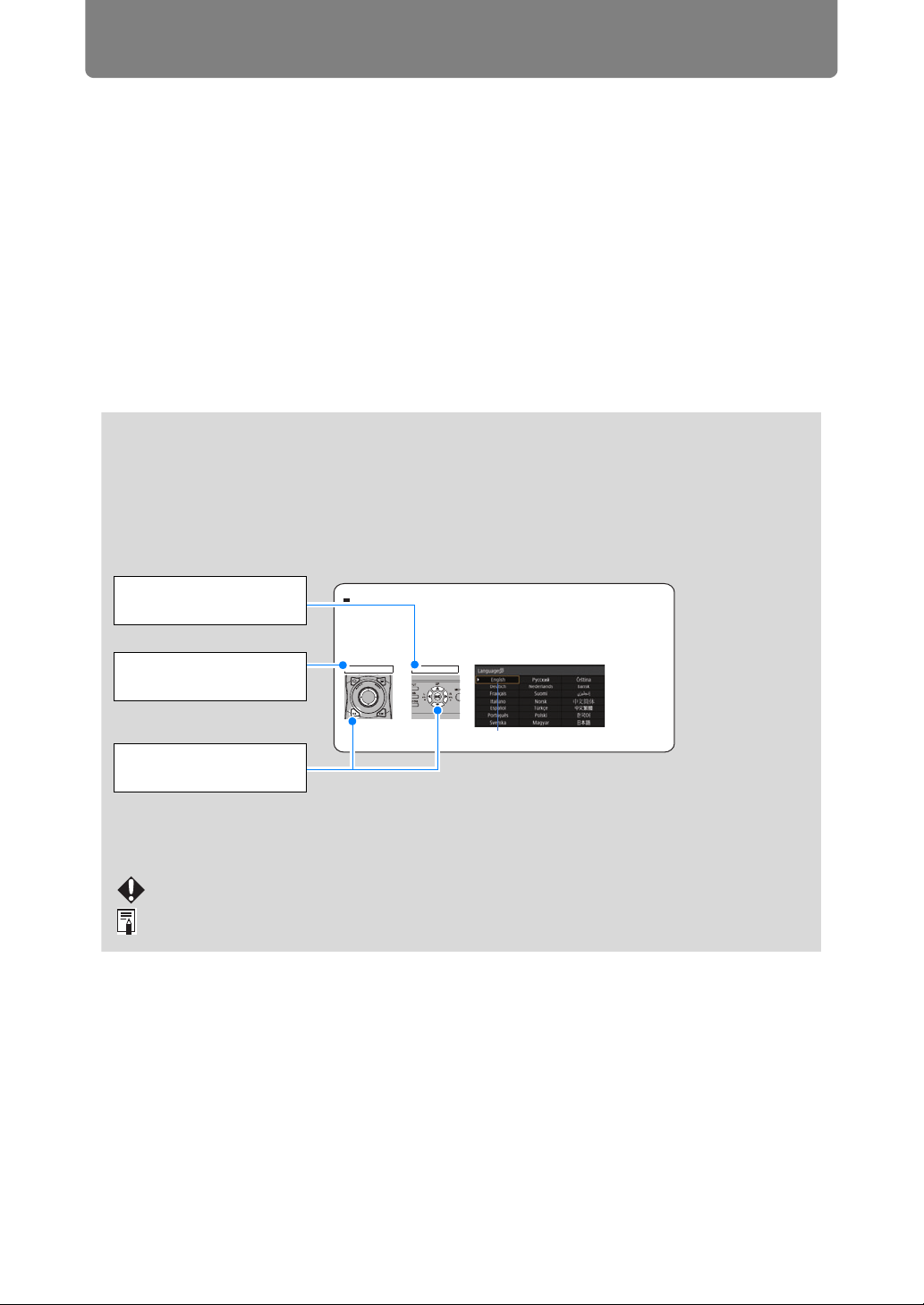
When the Language Selection Screen Appears
A screen appears when the projector is turned on for the first time. You can select a
language to be used by the projector for displaying menus and messages in the
window. Select the desired language with the pointer buttons and press the OK
button.
You can change the language from the menu at a later time. (P116)
If the language selection screen is out of focus, adjust the focus. (P67
Remote control Projector
)
operation
An item highlighted in orange will be selected.
Indicate the buttons to
be pressed
Symbols Used in This Manual
Sections labeled with these symbols give the following kinds of information.
A precaution about operation or restriction is given here.
Indicates supplemental information to note in use.
2
Page 3

Table of Contents
How to Use This Manual............... 2
Projector Highlights...................... 4
Safety Instructions........................ 5
Precautions for Use ............................. 12
Installation and Handling
Precautions .......................................... 13
Precautions on the Lamp .................... 14
Precautions for the Batteries of the
Remote Control .................................... 15
For Safe Use ................................ 17
Before Installation....................... 18
Precautions When Carrying/Shipping
the Projector......................................... 18
Precautions for Installation................. 18
Open Source Software ............... 23
Before Use ................................... 24
Included Accessories .......................... 24
Part Names ........................................... 25
Preparing the Remote Control............ 32
Basic Guide ............................35
Installation Procedure ................ 36
Setting Up the Projector...................... 36
Ceiling Mounting.................................. 38
Parts Lineup ......................................... 39
Mounting Position................................ 40
Assembly and Installation................... 42
Adjust the Projection Angle................ 48
Relationship between Projecting
Distance and Image Size ..................... 50
Lens Shift Function ............................. 51
Connection Procedure ............... 53
Connecting a Computer ...................... 53
Connecting AV Equipment.................. 54
Multi Input 4K Projection..................... 55
Plugging the Projector In .................... 59
Projection Procedure.................. 60
Step 1 Turn the Projector On .............. 60
Step 2 Select an Input Signal.............. 63
Step 3 Adjust the Image ...................... 65
Step 4 Select an Aspect Ratio (Screen
Aspect) Matching the Screen.............. 72
Step 5 Adjusting Keystone
Distortion .............................................. 73
Step 6 Select the Image Quality (Image
Mode) .................................................... 76
Step 7 Turn the Projector Off.............. 79
Convenient Features...................80
Advanced Guide ....................83
Using Menus ................................84
Menu Configuration ............................. 84
Basic Menu Operations ....................... 85
Menu Settings..............................87
Input settings ....................................... 87
Image adjustment ................................ 90
Install settings...................................... 97
System settings ................................. 108
Network settings ................................ 122
Completing Computer Settings for a
Network Connection .......................... 130
Checking Projector Information ....... 148
Advanced Projection.................149
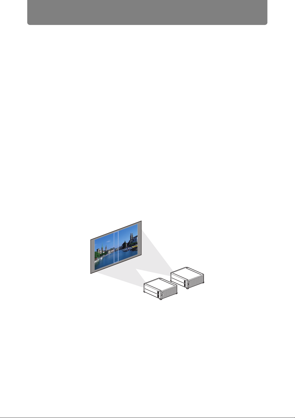
Projecting from Multiple Projectors at
Once (Edge Blending) ....................... 149
Advanced Registration to Adjust
Projected Images ............................... 153
Adjusting Peripheral Focus .............. 157
Other Information ................159
Maintenance...............................160
Cleaning the Projector....................... 160
Cleaning the Air Filter........................ 160
Replacing the Air Filter...................... 161
Replacing the Lamp........................... 163
Replacement Lamp ............................ 164
Lamp Replacement Procedure ......... 165
Product Specifications .............168
Displayed Test Patterns .................... 168
Supported Signal Types.................... 169
Specifications..................................... 174
Troubleshooting........................180
LED Indicator Details......................... 180
Symptoms and Solutions.................. 181
Index...........................................186
Option......................................... 188
3
Page 4
Projector Highlights
4K Projection Using 4096 x 2400 LCOS Panels
Outstanding projection resolution of up to 4096 x 2400 is possible, using three
0.76 inch liquid crystal on silicon (LCOS) panels in conjunction with dual highperformance image processors and a new 4K-compatible wide zoom lens.
Bright Yet Compact
Projects images at a bright 5,000 lumens but is also compact, at 470 x 533.5 x
175 mm (18.5 x 6.9 x 21.0 in., W x D x H). (P174)
Supports Fully Digital Input
Projects multiple sources of input in 4K, with two terminals for HDMI and four for
DVI input. A single HDMI terminal can be used for 3840 x 2160 (30 Hz) video
signals. (P55)
Peripheral Focus Adjustment
Image focus can be adjusted on the edges of the screen, enabling use in dome
projection. (P102, P157)
Edge Blending
Blend the overlapping edges of images from multiple projectors to make the overall
image more seamless. (P103)
High-Precision Image Registration
Precise correction of red, green, or blue misalignment in different areas of the
screen is possible by color and area. (P101)
Superior Video Viewing Experience
Refinements in motion blur reduction make video projection more enjoyable to
watch. (P115)
4
Page 5
Safety Instructions
Before installing and operating the projector, read this manual thoroughly.
This projector provides many convenient features and functions. Operating the
projector properly enables you to manage those features and maintain it in good
condition for many years to come.
Improper operation may result in not only shortening the product life, but also
malfunctions, fire hazards, or other accidents.
If your projector does not seem to be operating properly, read this manual again,
check operations and cable connections, and try the solutions in the
“Troubleshooting” section in the back of this manual. If the problem still persists,
contact the Canon Customer Support Center.
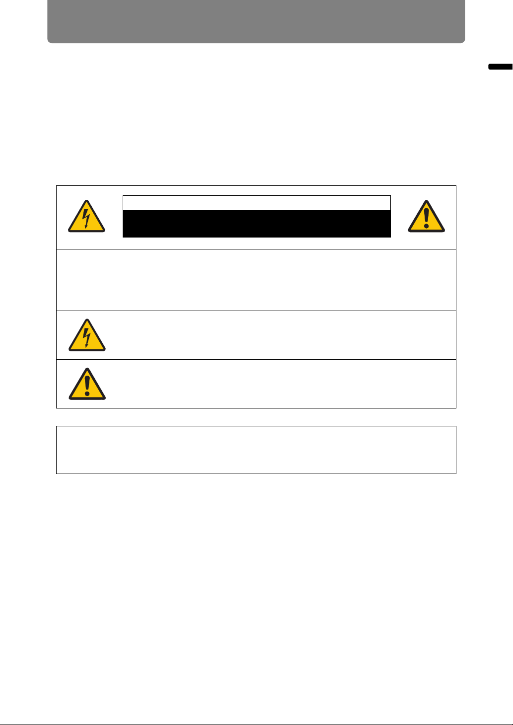
CAUTION
RISK OF ELECTRIC SHOCK
DO NOT OPEN
CAUTION: TO REDUCE THE RISK OF ELECTRIC SHOCK, DO NOT
REMOVE COVER (OR BACK). NO USER-SERVICEABLE PARTS
INSIDE EXCEPT LAMP REPLACEMENT. REFER SERVICING TO
QUALIFIED SERVICE PERSONNEL.
Safety Instructions
THIS SYMBOL INDICATES THAT DANGEROUS VOLTAGE
CONSTITUTING A RISK OF ELECTRIC SHOCK IS PRESENT
WITHIN THIS UNIT.
THIS SYMBOL INDICATES THAT THERE ARE IMPORTANT
OPERATING AND MAINTENANCE INSTRUCTIONS FOR THIS
UNIT IN THE OWNER’S MANUAL.
CAUTION
Not for use in a computer room as defined in the Standard for the Protection of
Electronic Computer / Data Processing Equipment, ANSI / NFPA 75.
5
Page 6
Safety Instructions
Safety Precautions
WARNING:
• THIS APPARATUS MUST BE GROUNDED.
• TO REDUCE THE RISK OF FIRE OR ELECTRIC SHOCK, DO NOT EXPOSE
THIS APPLIANCE TO RAIN OR MOISTURE.
• This projector produces intense light from the projection lens. Do not stare
directly into the lens, otherwise eye damage could result. Be especially careful
that children do not stare directly into the beam.
• Install the projector in a proper position. Otherwise it may result in a fire hazard.
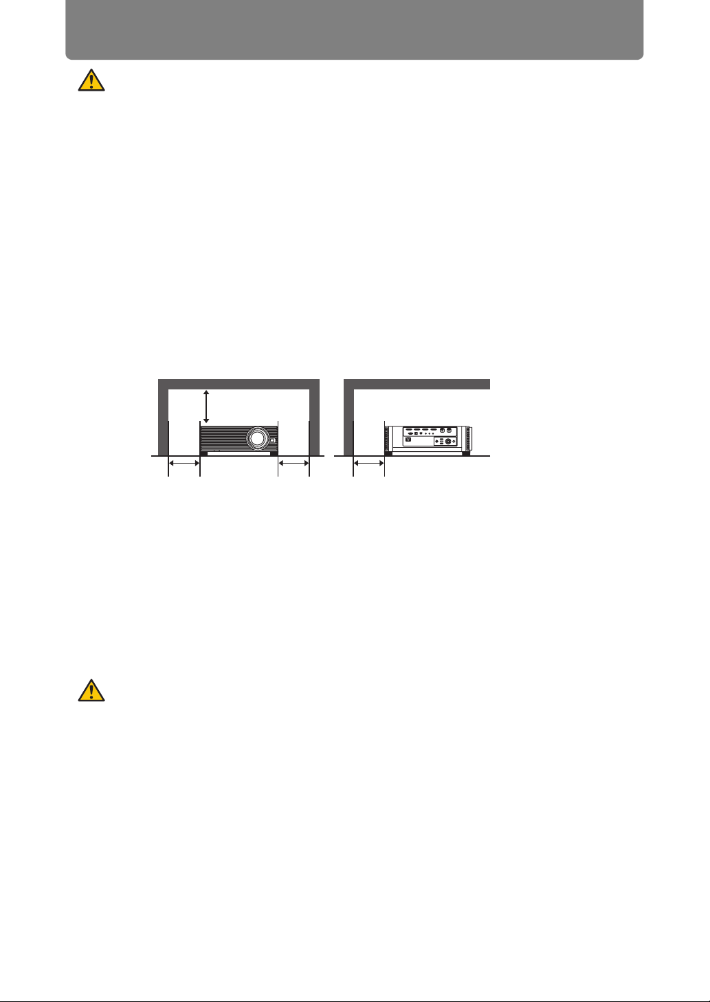
• Allowing the proper amount of space on the top, sides, and rear of the projector
cabinet is critical for proper air circulation and cooling of the unit. The diagrams
shown here indicates the minimum space required. If the projector is to be built
into a compartment or similarly enclosed, these minimum distances must be
maintained.
SIDE and TOP REAR
50 cm (1.6')
50 cm
(1.6')
• Do not cover the ventilation slots on the projector. Heat build-up can reduce the
service life of your projector, and can also be dangerous.
• If the projector is unused for an extended time, unplug the projector from the
power outlet.
• Do not project the same image for a long time.
An afterimage may remain on the LCD panels due to the characteristics of the
panels of the projector.
50 cm
(1.6')
50 cm
(1.6')
CAUTION ON HANGING FROM THE
CEILING
When hanging the projector from the ceiling, clean the air intake vents and top of
the projector periodically with a vacuum cleaner. If you leave the projector unclean
for a long time, the cooling fans can be clogged with dust, and it may cause a
breakdown or a disaster.
DO NOT SET THE PROJECTOR IN GREASY, WET, OR SMOKY CONDITIONS
SUCH AS IN A KITCHEN TO PREVENT A BREAKDOWN OR A DISASTER. IF
THE PROJECTOR COMES IN CONTACT WITH OIL OR CHEMICALS, IT MAY
BECOME DETERIORATED.
6
Page 7

Safety Instructions
■ READ AND KEEP THIS OWNER’S MANUAL FOR LATER
USE.
All the safety and operating instructions should be read before beginning to operate
the product.
Read all of the instructions given here and retain them for later use. Unplug this
projector from the AC power supply before cleaning. Do not use liquid or aerosol
cleaners on the projector. Use a damp cloth for cleaning.
Follow all warnings and instructions marked on the projector.
For added protection of the projector during a lightning storm, or when it is left
unattended or unused for long periods of time, unplug it from the wall outlet. This
will prevent damage due to lightning and power surges.
Do not expose this unit to rain or use near water... for example, in a wet basement,
near a swimming pool, etc...
Do not use attachments not recommended by the manufacturer as they may result
in hazards.
Safety Instructions
Do not place this projector on an unstable cart, stand, or table. The projector may
fall, causing serious injury to a child or adult, and serious damage to the projector.
Use only with a cart or stand recommended by the manufacturer, or sold with the
projector. Wall or shelf mounting should be carried out in accordance with the
manufacturer’s directions, and should use a mounting kit approved by the
manufacturers.
An appliance and cart combination should be moved with care.
Sudden stops, excessive force, and uneven surfaces may cause
the appliance and cart combination to overturn.
Slots and openings in the rear and front of the cabinet are provided
for ventilation, to insure reliable operation of the equipment and to protect it from
overheating.
The openings should never be covered with cloth or other materials, and the
bottom opening should not be blocked by placing the projector on a bed, sofa, rug,
or other similar surface. This projector should never be placed near or over a
radiator or heat register.
This projector should not be placed in a built-in installation such as a book case
unless proper ventilation is provided.
7
Page 8

Safety Instructions
Never push objects of any kind into this projector through cabinet slots as they may
touch dangerous voltage points or short out parts that could result in a fire or
electric shock. Never spill liquid of any kind onto the projector.
Do not install the projector near the ventilation duct of air-conditioning equipment.
This projector should be operated using only the type of power source indicated on
the marking label. If you are not sure of the type of power supplied, contact the
Canon Customer Support Center or local power company.
Do not overload wall outlets and extension cords as this can result in fire or electric
shock. Do not allow anything to rest on the power cord. Do not locate this projector
where the cord may be damaged by people walking on it.
Do not attempt to service this projector yourself as opening or removing covers
may expose you to dangerous voltages or other hazards. Refer all servicing to
qualified service personnel.
Unplug this projector from the wall outlet and refer servicing to qualified service
personnel under the following conditions:
a. When the power cord or plug is damaged or frayed.
b. If liquid has been spilled into the projector.
c. If the projector has been exposed to rain or water.
d. If the projector does not operate normally after following the operating
instructions. Adjust only those controls that are covered in the operating
instructions as improper adjustment of other controls may result in damage and
will often require extensive work by a qualified technician to restore the projector
to normal operating condition.
e. If the projector has been dropped or the cabinet has been damaged.
f. When the projector exhibits a distinct change in performance-this indicates a
need for servicing.
When replacement parts are required, be sure the service technician uses
replacement parts specified by the manufacturer that have the same characteristics
as the original parts. Unauthorized substitutions may result in fire, electric shock, or
injury.
Upon completion of any service or repairs to this projector, ask the service
technician to perform routine safety checks to determine that the projector is in safe
operating condition.
8
Page 9
Safety Instructions
AC Power Cord Requirement
The AC Power Cord supplied with this projector meets the requirements for use in
the country you purchased it.
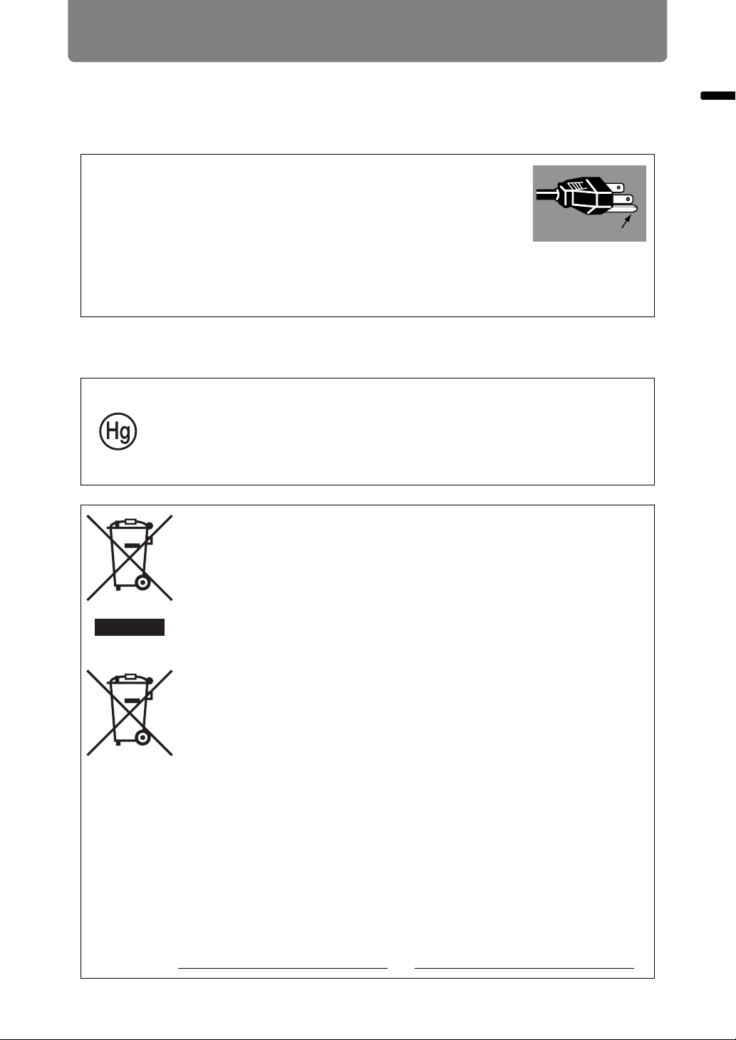
AC Power Cord for the United States and Canada:
The AC Power Cord used in the United States and Canada is
listed by the Underwriters Laboratories (UL) and certified by
the Canadian Standard Association (CSA).
The AC Power Cord has a grounding-type AC line plug. This is
a safety feature to ensure the plug fits into the power outlet. Do
not try to tamper with this safety feature. Should you be unable
to insert the plug into the outlet, contact your electrician.
THE SOCKET-OUTLET SHOULD BE INSTALLED NEAR THE EQUIPMENT AND
EASILY ACCESSIBLE.
For the U.S. and Canada, LAMP (S) INSIDE THIS PRODUCT CONTAIN
MERCURY AND MUST BE RECYCLED OR DISPOSED OF ACCORDING
TO LOCAL, MUNICIPAL, STATE, PROVINCIAL, OR FEDERAL LAWS.
For lamp recycling and disposal information please call 1-800-OK-CANON
for the U.S. and Canada.
Ground
Safety Instructions
Only for European Union and EEA (Norway, Iceland and
Liechtenstein)
These symbols indicate that this product is not to be disposed of
with your household waste, according to the WEEE Directive (2012/
19/EU), the Battery Directive (2006/66/EC) and/or national
legislation implementing those Directives.
If a chemical symbol is printed beneath the symbol shown above, in
accordance with the Battery Directive, this indicates that a heavy
metal (Hg = Mercury, Cd = Cadmium, Pb = Lead) is present in this
battery or accumulator at a concentration above an applicable
threshold specified in the Battery Directive.
This product should be handed over to a designated collection point,
e.g., on an authorized one-for-one basis when you buy a new similar
product or to an authorized collection site for recycling waste
electrical and electronic equipment (EEE) and batteries and
accumulators. Improper handling of this type of waste could have a
possible impact on the environment and human health due to
potentially hazardous substances that are generally associated with
EEE. Your cooperation in the correct disposal of this product will
contribute to the effective usage of natural resources.
For more information about the recycling of this product, please
contact your local city office, waste authority, approved scheme or
your household waste disposal service or visit
www.canon-europe.com/weee
, or www.canon-europe.com/battery.
9
Page 10

Safety Instructions
Federal Communication Commission Notice
Model: 4K500ST
This device complies with Part 15 of the FCC Rules. Operation is subject to the
following two conditions:
1. This device may not cause harmful interference, and
2. This device must accept any interference received, including interference that
may cause undesired operation.
Note: This equipment has been tested and found to comply with the limits for a
Class A digital device, pursuant to Part 15 of the FCC Rules. These limits are
designed to provide reasonable protection against harmful interference when the
equipment is operated in a commercial environment. This equipment generates,
uses, and can radiate radio frequency energy and, if not installed and used in
accordance with the instruction manual, may cause harmful interference to radio
communications. Operation of this equipment in a residential area is likely to
cause harmful interference in which case the user will be required to correct the
interference at his own expense. The cable with a ferrite core provided with the
projector must be used with this equipment in order to comply with Class A of the
FCC Rules. Use of a shielded cable is required to comply with Class A of FCC
Rules. Do not make any changes or modifications to the equipment unless
otherwise specified in the instructions. If such changes or modifications should be
made, you could be required to stop operation of the equipment.
Warning:
This is a class A product. In a domestic environment this product may cause radio
interference in which case the user may be required to take adequate measures.
The cable with a ferrite core provided with the projector must be used with this
equipment in order to comply with Class A .
Use of a shielded cable is required to comply with Class A .
10
Page 11
Safety Instructions
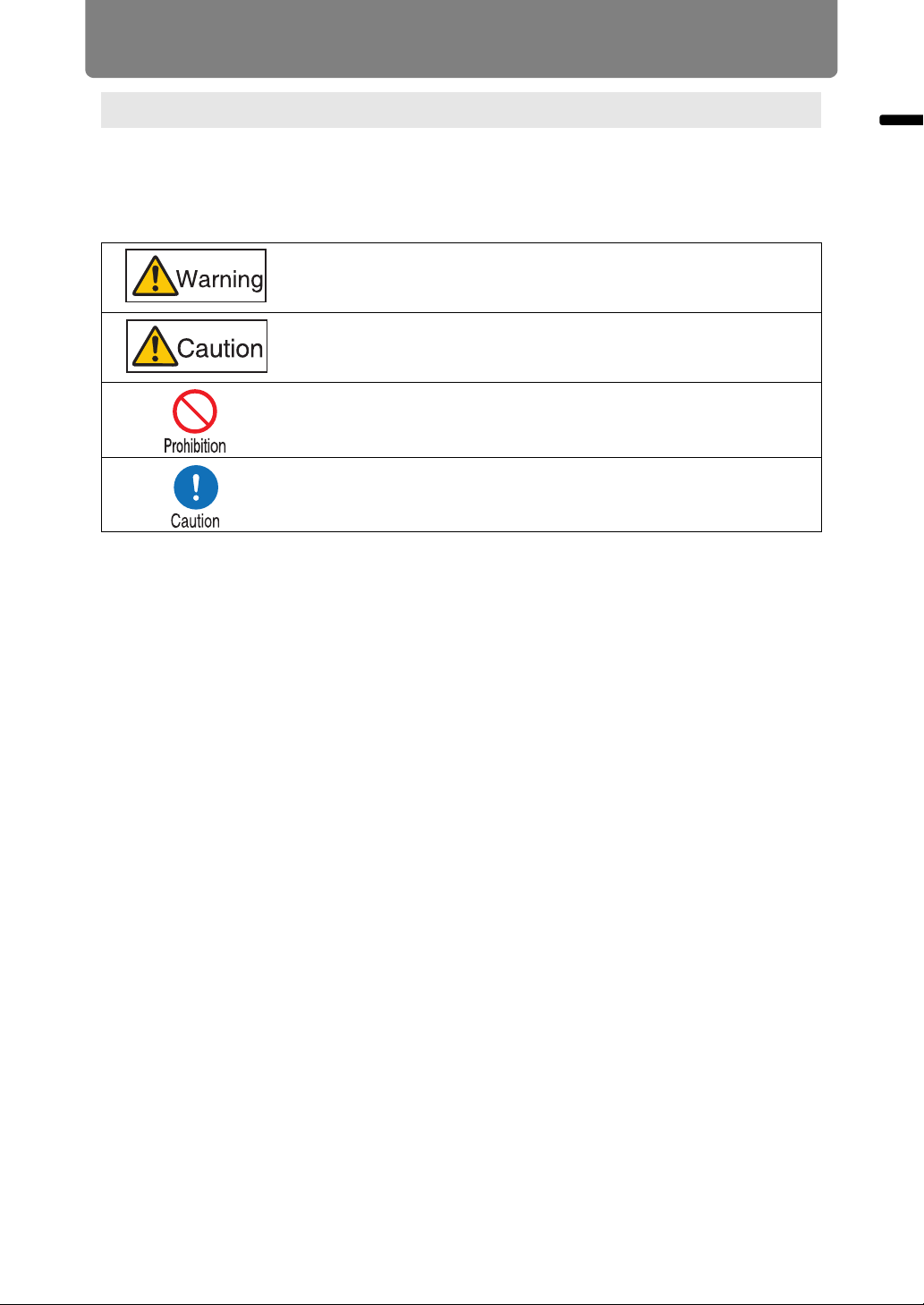
Safety Symbols in this Manual
This section describes the safety symbols used in this manual. Important projector
safety information is identified by the following symbols. Always observe the safety
information by these symbols.
Denotes the risk of death or serious injury from improper
handling if the information is not observed. To ensure safe use,
always observe this information.
Denotes the risk of injury from improper handling if the
information is not observed. To ensure safe use, always observe
this information.
Denotes prohibited actions.
Denotes required actions or information that must be observed.
Safety Instructions
11
Page 12
Safety Instructions
Precautions for Use
As this section contains important safety-related information, be sure to read the
following carefully beforehand in order to use your projector correctly and safely.
During installation, keep the projector plug easily accessible so that the projector can be
unplugged immediately if necessary, or keep a circuit breaker within reach.
If the following situations occur, turn the power off, remove the power plug from the
power outlet and contact the Canon Customer Support Center. Failure to do so could
cause a fire or result in an electric shock.
• If smoke is emitted
• If an unusual smell or noise is emitted
• If water or other liquid has entered the projector
• If metal or any other foreign material has entered the projector
• If the projector is knocked over or dropped and the cabinet is damaged
Pay attention to the following points for handling the power cord. Failure to do so may
cause a fire, electric shock or personal injury.
• Do not place any objects on the power cord and do not allow it to become
trapped under the projector.
• Do not cover the power cord with a carpet.
• Do not modify or excessively bend, twist, pull, wind, or bundle the power
cord.
• Keep the power cord away from heaters and other sources of heat.
• Do not use a damaged power cord. If the power cord is damaged, purchase
a replacement from your dealer.
• The power cord included with this projector is for use exclusively with this
product. Do not use this cord for other products.
• Be sure to connect the ground wire of the power cord to ground.
• Be sure to connect the ground wire before connecting the power plug to the
outlet. Also when you disconnect the ground wire, be sure to unplug the
power plug from the outlet beforehand.
12
Page 13
Safety Instructions
Pay attention to the following points regarding the power source, power plug and
handling of the connector. Failure to do so may cause a fire, electric shock or personal
injury.
•
Do not use any power source with a voltage other than the voltage indicated
(AC 100–240 V).
• Do not pull the power cord and be sure to hold the power plug or connector
when removing. Incorrect handling may damage the power cord.
• Do not insert any metal objects into the contact parts of the power plug or
connector.
• Do not remove the power plug or connector with wet hands.
• Insert the power plug and connector securely up to the base. Additionally, do
not use a damaged power plug or an outlet that is loose.
• When using an extension cord, do not exceed the cord’s rated capacity.
• Periodically inspect the power plug and outlet and remove any dust or dirt
from between the plug and the outlet.
Safety Instructions
Installation and Handling Precautions
Pay attention to the following points regarding installation and handling of the projector.
Failure to do so may cause a fire, electric shock or personal injury.
• Do not use the projector where it might get wet, such as outdoors or by
bathtubs or showers.
• Do not place containers containing a liquid on top of the projector.
• Do not touch the projector itself, the power cord, or the cable if lightening
strikes.
• Do not move the projector until you have switched off the power, removed
the power plug from the power outlet and unplugged any other cables.
• Unplug the projector before cleaning or maintenance.
13
Page 14
Safety Instructions
Pay attention to the following points regarding installation and handling of the projector.
Failure to do so may cause a fire, electric shock or personal injury.
• Do not remove the cabinet from the projector or disassemble it. The interior
of the projector contains high-voltage components as well as parts that are
hot. If inspection, maintenance or repair is required, contact the Canon
Customer Support Center.
• Do not disassemble or modify the projector (including consumable parts) or
the remote control.
• Do not look directly into the exhaust vents during use.
• Do not insert any object into vents in the projector, such as the air intake vent
or exhaust vents.
• Do not place a pressurized can in front of the exhaust vents. The pressure of
the contents of the can may increase due to heat from the exhaust vents and
this could result in an explosion.
• When cleaning off dust or dirt from the projector lens etc., do not use any
kind of spray that is flammable. As the temperature of the lamp inside the
projector is high, it could ignite, causing a fire.
• As strong light beams are emitted while the projector is in use, do not look
directly into the projector lens. Doing so could cause an eye injury. Pay
particular attention to prevent small children from doing so.
• When setting the projector on a high surface for projection, be sure the
surface is flat and stable.
• For ceiling mounting precautions, refer to the installation manual included
with the ceiling mount (sold separately).
Precautions on the Lamp
This projector uses a high-pressure mercury lamp, which must be handled
carefully and correctly as described below.
The mercury lamp has the following characteristics.
• The lamp will gradually become darker over time.
• Impact, abrasion, or use of worn-out lamps may cause lamps to rupture
(accompanied by a loud noise) or burn out.
• Lamps are more likely to rupture after the lamp replacement message is
displayed (see “Replacing the Lamp” (P163)). Replace the lamp with a new
one as soon as possible.
• Useful life of lamps varies widely from lamp to lamp and depending on the
environment of use. Some lamps may fail or rupture soon after they are first
used.
• Be prepared by keeping a spare lamp.
14
Page 15
Safety Instructions
Note the following precautions during lamp replacement or when a lamp has ruptured.
Failure to do so could result in an electric shock or personal injury.
• Before replacing the lamp, always unplug the projector and wait at least an
hour.
• Ruptured lamps may scatter shards of glass inside the projector. Contact the
Canon Customer Support Center for cleaning and inspection of the projector
interior and lamp replacement.
Precautions when replacing lamps that stop working
• If illumination suddenly stops, either when you turn the projector on or after it
has been on for a while, the lamp may have ruptured. In this case, never
attempt to replace the lamp by yourself. Always request service from the
Canon Customer Support Center.
• With ceiling-mounted projectors, the lamp may fall out when you open the
lamp cover, or during replacement. During replacement, stand to the side of
the lamp cover, not directly under it.
• If the lamp ruptures, dust and gas (containing mercury vapor) may come out
of the exhaust vents. If this happens, immediately open the windows and
doors to provide ventilation to the room.
• If you accidentally inhale gas from the lamp or get any pieces in your eyes or
mouth, consult a doctor immediately.
Safety Instructions
Precautions for the Batteries of the Remote Control
Pay attention to the following points regarding handling of batteries. Failing to do so
could result in a fire or personal injury.
•
Do not heat, short circuit or disassemble the batteries, or place them in a fire.
• Do not attempt to recharge the batteries that are included with the remote
control.
• Remove the batteries when they are flat or when the remote control will not
be used for a long period of time.
• When replacing the batteries, replace both at the same time. Also, do not
use two batteries of a different type at the same time.
• Insert the batteries with the + and - terminals in the correct directions.
• If any liquid from inside the batteries leaks out and contacts your skin, be
sure to wash the liquid off thoroughly.
15
Page 16
Safety Instructions
Pay attention to the following points regarding installation and handling of the projector.
• If the projector will not be used for a long period of time, be sure to remove
the power plug from the power outlet to ensure safety. Failure to do so
presents a risk of fire if dust accumulates on the plug or outlet.
• Parts of the cabinet around and above the exhaust vents may become hot
during projection. Touching these areas during operation could cause burns
to the hands. Pay particular attention in preventing young children from
touching these parts. Additionally, do not place any metal objects around or
above the exhaust vents. Due to the heat from the projector, doing so could
cause an accident or personal injury.
• Do not place the projector where it may be exposed to oily smoke or steam,
such as near kitchen counters or humidifiers. Doing so may cause fire or
electric shock.
• Do not place any heavy objects on top of the projector or sit / stand on it. Pay
particular attention to prevent small children from doing so. The projector
may be knocked over and this could result in damage or a personal injury.
• Do not place the projector on an unstable or slanted surface. Doing so may
cause the projector to fall or be knocked over and could result in a personal
injury.
• Do not place any objects in front of the lens during projection. Doing so could
cause a fire.
• Presenters in front of the projector should stand where the light does not
seem too bright, and where their shadow does not fall on the screen.
When handling the lamp, pay attention to the following points.
• Be sure not to handle the lamp immediately after it has been used. Be sure
to switch off the power and wait for approximately 1 hour for the lamp and
the projector to cool down sufficiently. Failure to do so could result in a burn
or personal injury due to heat from the lamp or projector.
16
Page 17
For Safe Use
Pay attention to the following points when carrying or transporting the projector.
• This projector is a precision instrument. Do not knock it over or subject it to
impacts. Doing so may cause a malfunction.
• Do not reuse any packaging or shock-absorbent materials that were
supplied with the projector at the time of purchase for transporting or
shipping the projector. Protection of the projector cannot be guaranteed if
used packaging or shock-absorbent materials are reused. Fragments from
shock-absorbent material may also enter the interior of the projector which
could cause a malfunction.
• Disconnect the cables connected to the projector. Carrying the projector
while the cables are attached may cause an accident.
• Retract the adjustable feet before moving the projector. Leaving the feet
extended may cause damage.
Pay attention to the following points when installing or using the projector.
• Do not touch the lens with bare hands. Doing so may result in deterioration
of image quality.
• If the projector is abruptly taken from a cool to a warm location,
condensation may form on the lens or mirrors, which may cause a blurred
image. Wait until the condensation has evaporated for the image projected
to return to normal.
• Do not install the projector in a location where the temperature is high or low.
Doing so may cause a malfunction. For guidelines on operating
temperatures, see “Product Specifications”.
• Do not place any objects on top of the projector that may change shape or
color due to heat.
• Projector settings must be adjusted when using the projector at high
altitudes or in upward or downward projection. Failure to adjust the settings
may shorten the lamp life or damage the lamp. For details, contact the
Canon Customer Support Center.
• Do not install the projector near high-voltage electrical power lines or an
electrical power source.
• Do not use the projector on a soft surface such as carpet or sponge mat, etc.
Doing so could cause heat to build up inside the projector and this could
result in a malfunction.
• Do not block the air intake or exhaust vents of the cooling fan. If the air
intake or exhaust vent is blocked, heat cannot be released from inside the
projector, which may shorten the useful life of the lamp or cause malfunction.
• Installing the projector in the wrong direction may cause a malfunction or
accident. Do not install the projector with one side raised, or with the
projector tilted toward the left or right.
• Install the projector with sufficient space between air intakes and exhaust
vents and walls. Failure to do so could cause a malfunction.
• Do not install the projector in a location that is damp, or where there is a lot
of dust, oily smoke or tobacco smoke. Doing so could cause contamination
of optical components such as the lens and the mirror and may result in
deterioration of image quality.
For Safe Use
17
Page 18
Before Installation
Precautions When Carrying/Shipping the Projector
Prepare the projector as described below before carrying it.
• Disconnect the cables connected to the projector. Carrying the
projector with the cables attached may cause an accident.
• Retract the adjustable feet before moving the projector. Leaving
the feet extended may cause damage.
• Do not carry or move the projector alone. Have at least one
assistant.
Precautions for Installation
Be sure to read “Safety Instructions” and “For Safe Use” (P5 – P17). Also
take the following precautions during installation.
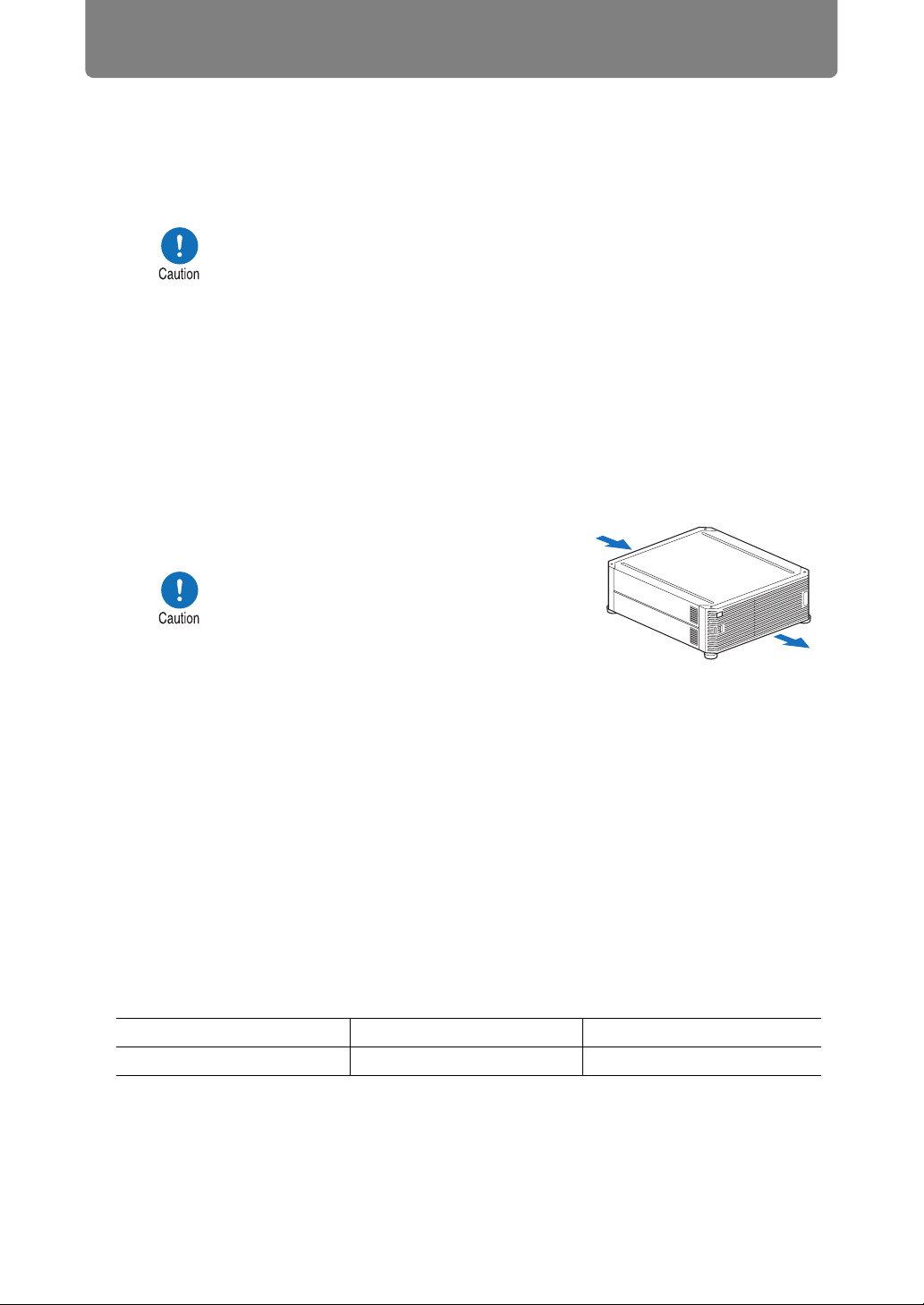
• Do not strike the projector or
subject it to impact. Doing so may
cause a malfunction.
• Do not install the projector so that it
is inclined or standing vertically. The
projector may be damaged if it tips
over.
• Do not block the air intake or
exhaust vents of the cooling fan.
Blocking the vents may trap heat inside the projector, which
may shorten the useful life of the lamp or damage the projector.
Air intake vent
Exhaust vent
■ Do Not Use in the Following Environments
• Locations with excessive humidity, dust, oily smoke or tobacco smoke
Adhesion to the lens, mirrors or other optical parts may reduce image quality.
• Near high-voltage power lines or sources of electrical power
This may cause malfunction.
• On soft surfaces such as carpets or cushioned mats
Heat may build up inside the projector and damage it.
• Locations with excessive temperature or humidity
This may damage the projector. Acceptable ranges for operating and storage
temperature and humidity are as follows.
Operating temperature Operating humidity Storage temperature
0°C (32°F) – 40°C (104°F)
Up to 85%
18
-20°C (-4°F) – 60°C (140°F)
Page 19
Before Installation
■ Do Not Touch the Lens with Bare Hands
Do not touch the lens with bare hands. Doing so may adversely affect picture
quality.
■ Allow a 30 Min. Warm Up before Focus Adjustment (P67), if Possible
The focus position may not stabilize immediately after startup, due to lamp heat.
When adjusting focus, it is also helpful to use the test pattern (10) (P107, P168).
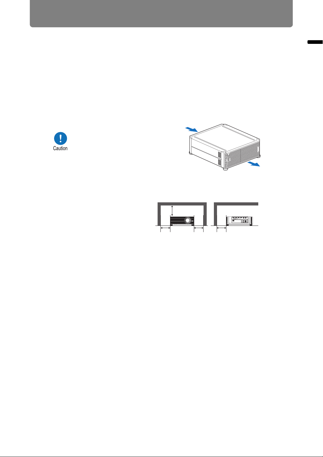
■ Install at a Sufficient Distance from Walls and Other Obstructions
Before Installation
If the air intake or exhaust vent
is blocked, heat will accumulate
inside the projector, possibly
resulting in a shortened
projector lifetime or a
malfunction. Do not install in a
closet, on a bookshelf, or in
other narrow spaces with poor
ventilation. Install in a wellventilated location. (Ensure a minimum clearance of 50 cm (1.6 ft.)
above, on both sides, and behind the projector, as shown below.)
50 cm
(1.6')
Air intake vent
50 cm (1.6')
50 cm
(1.6')
Exhaust vent
50 cm
(1.6')
■ Be Careful of Condensation
If the temperature of the room rises suddenly, moisture in the air may condense on
the projector lens and mirror, causing the image to become blurred. Wait until the
condensation has evaporated for the image projected to return to normal.
■ At Altitudes above 2,300 m (7,545.8'), Adjust the Settings
Projector settings must be adjusted when using the projector at altitudes of 2,300 m
(7,545.8') or higher. Specifically, refer to instructions for [High altitude] (P102) in the
[Install settings] menu.
19
Page 20
Before Installation
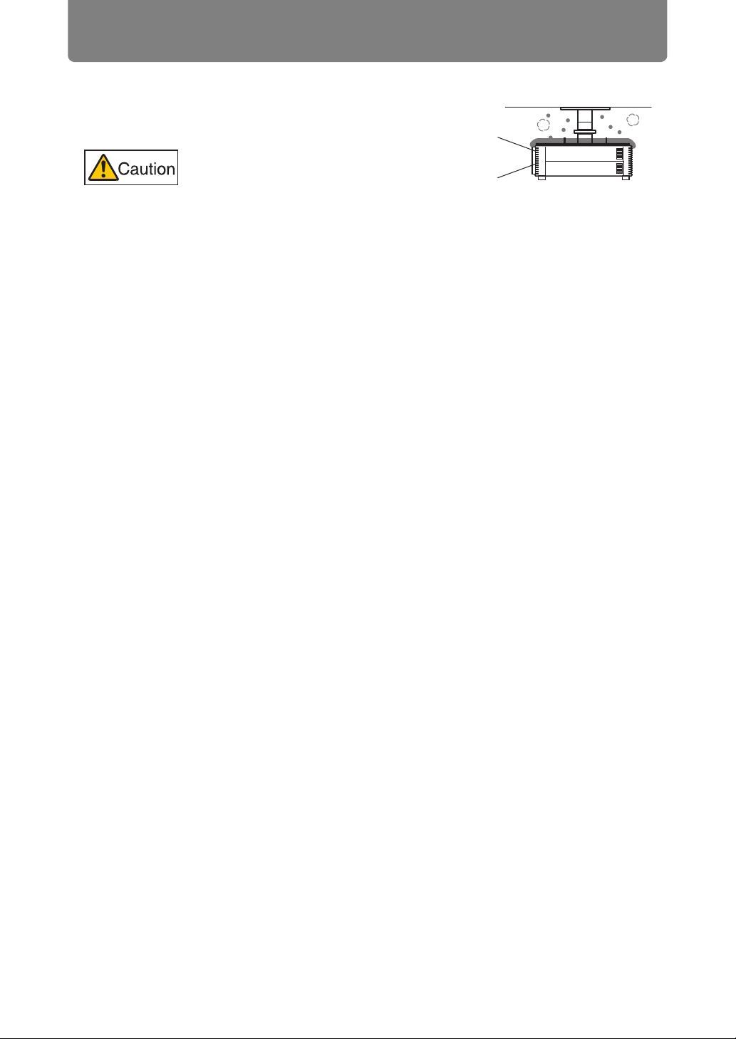
■ When Using Mounted on the Ceiling
When the projector is used mounted on the
ceiling or installed in a high location, it is
necessary to periodically clean the air
intake and exhaust vents, and the area
around the air filter. Dust that accumulates
in intake or exhaust vents may impair
ventilation, raising the temperature inside
and posing a risk of damage or fire. Use a
vacuum cleaner or similar means to
remove dust from the intake vent and
exhaust vent.
20
Page 21
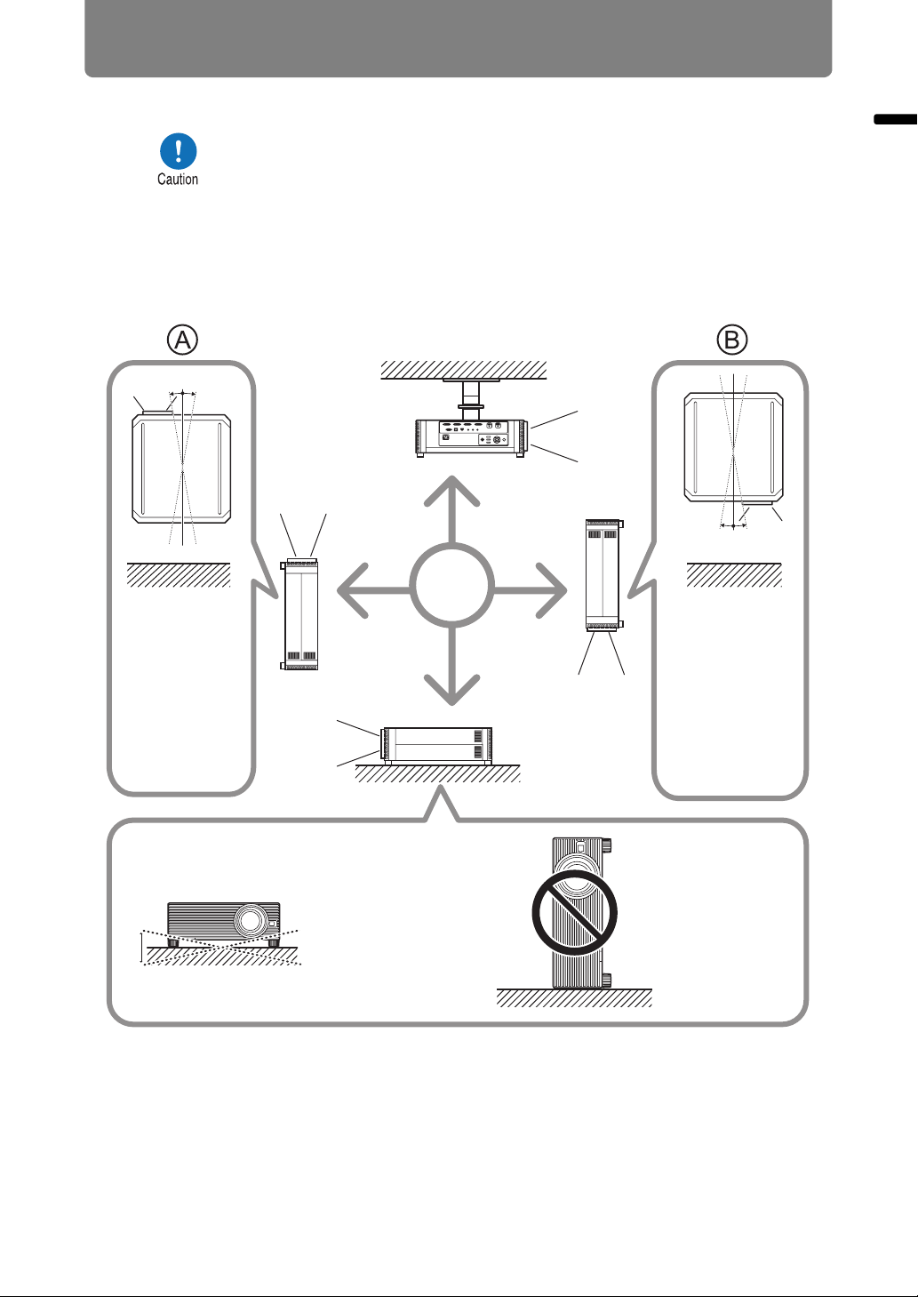
■ Install Facing in the Correct Direction
Before Installation
10° 10°
Upward
projection:
Inclination of the
projector should
be no more than
10° from the
vertical axis.*
2
• The projector can be installed facing any direction*1, as shown
below. However, projection upward or downward may shorten the
useful life of the lamp. [Install settings] of the projector must also
be adjusted. Specifically, for upward or downward projection, refer
to instructions for [Vertical projection] (P102) in the [Install
settings] menu.
• Do not attempt to install the projector for upward or downward
projection by yourself. Always request installation by a qualified
technician or the Canon Customer Support Center.
10° 10°
Downward
projection:
Inclination of the
projector should
be no more than
10° from the
vertical axis.
2
*
Before Installation
10°
10°
If installing the projector
on the floor or hanging
from the ceiling, the left /
right inclination of the
projector should be no
more than 10°.*
2
Do not use the
projector standing
on its side.
2
*
*1 No optional accessories are available for installing the projector in
ways other than ceiling installation (P37, P188).
*2 Failure to do so may damage the lamp.
21
Page 22
Before Installation
• When installing the projector facing upward or downward, specify which way the
projector is facing in [Install settings] > [Professional settings] > [Vertical projection].
(P102)
• When mounting the projector on the ceiling, it is more convenient to install the projector
right-side up, with the adjustable feet facing down.
Copyright Notice
Please note that enlarging or reducing the size of an image for commercial
purposes or public presentation may infringe on the legally protected copyright
or the copyright holder of the original material.
Ensure Network Security
Take measures to ensure network security. Note that Canon is not liable in any
way for direct or indirect loss from network security incidents, such as
unauthorized access.
Examples of Security Measures
• Use in an intranet environment.
• Assign a private IP address.
• Use behind a firewall.
• Change passwords regularly.
About Trademarks
• Ethernet is a registered trademark of Xerox Corporation.
• Microsoft, Windows, Windows Vista, Windows 7, Windows 8 and
Windows 8.1 are registered trademarks or trademarks of Microsoft
Corporation in the United States and / or other countries.
• Mac, Mac OS and Macintosh are trademarks of Apple Inc., registered in the
United States and / or other countries.
• HDMI, the HDMI logo and High-Definition Multimedia Interface are
trademarks or registered trademarks of HDMI Licensing, LLC.
• PJLink is a registered trademark of JBMIA and pending trademark in some
countries.
• PJLink is a registered trademark, or an application has been submitted for
trademark, in Japan, the United States and / or other countries or regions.
• AMX is a trademark of AMX Corporation.
• Crestron®, Crestron RoomView®, and Crestron Connected™ are registered
trademarks of Crestron Electronics, Inc.
• All other trademarks are the property of their respective owners.
22
Page 23

Open Source Software
The product contains Open Source Software modules. For details, see
“ThirdPartySoftware.pdf” (Third-Party Software License) in the
OpenSourceSoftware folder in the LICENSE folder on the Setup CD-ROM. Each
module’s license conditions are also available in the same folder.
■ Software under the GNU General Public License Version 2
Contained programs are free software; you can redistribute them and/or modify
them under the terms of the GNU General Public License attached to each copy of
the program.
Each program is distributed in the hope that it will be useful, but WITHOUT ANY
WARRANTY; without even the implied warranty of MERCHANTABILITY or
FITNESS FOR A PARTICULAR PURPOSE. Please see “NO WARRANTY” and
“NO SUPPORT” stated below. For more detail, please see full text of the GNU
General Public License.
NO WARRANTY
BECAUSE THE PROGRAM IS LICENSED FREE OF CHARGE, THERE IS NO
WARRANTY FOR THE PROGRAM, TO THE EXTENT PERMITTED BY
APPLICABLE LAW. EXCEPT WHEN OTHERWISE STATED IN WRITING THE
COPYRIGHT HOLDERS AND/OR OTHER PARTIES PROVIDE THE PROGRAM
“AS IS” WITHOUT WARRANTY OF ANY KIND, EITHER EXPRESSED OR
IMPLIED, INCLUDING, BUT NOT LIMITED TO, THE IMPLIED WARRANTIES OF
MERCHANTABILITY AND FITNESS FOR A PARTICULAR PURPOSE. THE
ENTIRE RISK AS TO THE QUALITY AND PERFORMANCE OF THE PROGRAM
IS WITH YOU. SHOULD THE PROGRAM PROVE DEFECTIVE, YOU ASSUME
THE COST OF ALL NECESSARY SERVICING, REPAIR OR CORRECTION.
Open Source Software
IN NO EVENT UNLESS REQUIRED BY APPLICABLE LAW OR AGREED TO IN
WRITING WILL ANY COPYRIGHT HOLDER, OR ANY OTHER PARTY WHO MAY
MODIFY AND/OR REDISTRIBUTE THE PROGRAM AS PERMITTED ABOVE, BE
LIABLE TO YOU FOR DAMAGES, INCLUDING ANY GENERAL, SPECIAL,
INCIDENTAL OR CONSEQUENTIAL DAMAGES ARISING OUT OF THE USE OR
INABILITY TO USE THE PROGRAM (INCLUDING BUT NOT LIMITED TO LOSS
OF DATA OR DATA BEING RENDERED INACCURATE OR LOSSES SUSTAINED
BY YOU OR THIRD PARTIES OR A FAILURE OF THE PROGRAM TO OPERATE
WITH ANY OTHER PROGRAMS), EVEN IF SUCH HOLDER OR OTHER PARTY
HAS BEEN ADVISED OF THE POSSIBILITY OF SUCH DAMAGES.
NO SUPPORT
Canon Inc., and all its subsidiaries or its dealers do not make any support service
regarding the source code. Canon Inc., and all its subsidiaries or its dealers shall
not respond to any questions or enquiries, from you or any other customers,
regarding the source code.
23
Page 24
Before Use
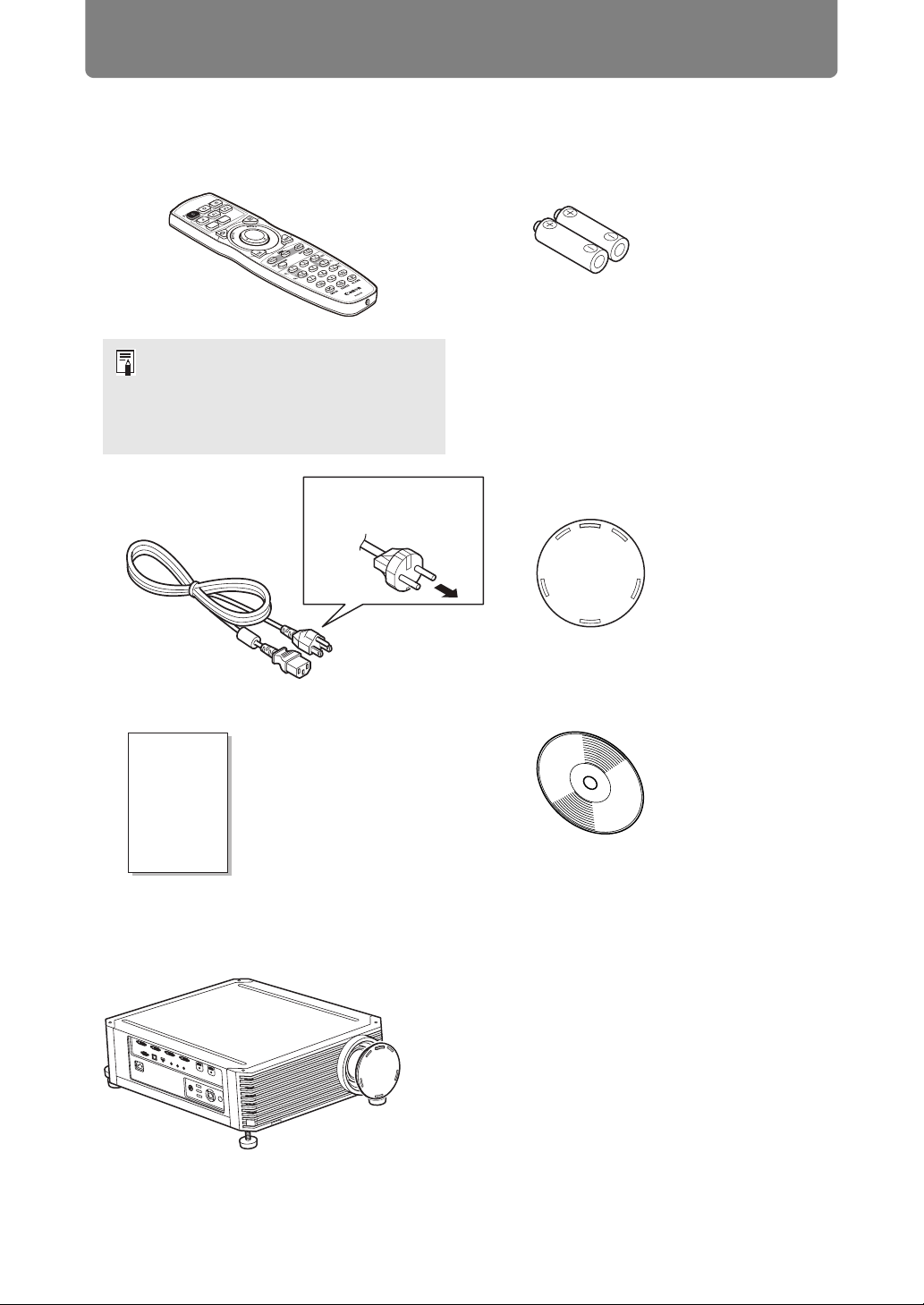
Included Accessories
Before use, make sure the following items are included in the package.
• Remote control • Batteries for the remote control
(AA size x2)
(part No.: RS-RC05)
Optional remote controls are also
available (RS-RC04). However, some
buttons are not supported with this
projector. The RS-RC05 can also be
used as a wired remote. (P33)
• Power cord
(1.8 m / 5.9')
For the U.S.A.
and Canada
• Important Information
• Warranty Card
For Continental
Europe
• Lens cap
• User’s Manual (CD-ROM)
■ Always remove the lens cap before projection.
24
Page 25
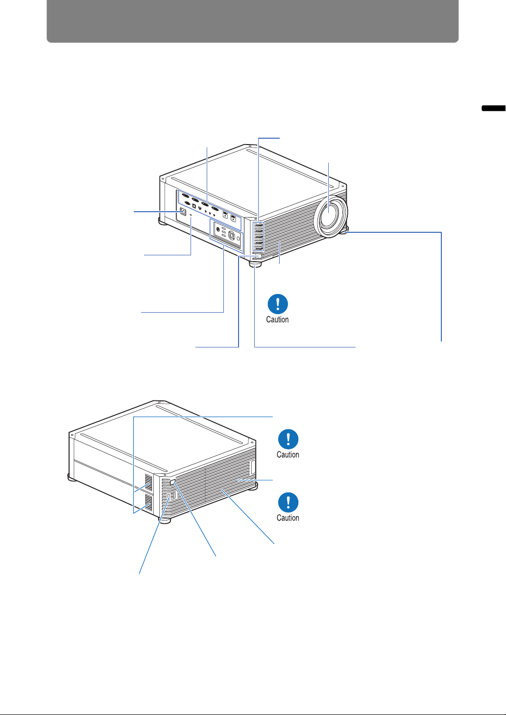
Part Names
Projector
Before Use
■ Front Side
Terminals and connectors (P29)
Power cord
connector (P59)
Anti-theft lock hole
An anti-theft wire
cable (not included)
can be connected.
Side control (P26)
Infrared remote receiver (P33)
■ Rear Side
Before Use
LED indicators (P27)
Projection lens
Air intake vent
Air filter (P161)
Do not block the air intake.
Doing so may cause a
malfunction.
Adjustable feet (P36)
Air intake vent
Do not block the air intake.
Doing so may cause a
malfunction.
Exhaust vent
Do not block the air exhaust.
Doing so may cause a
malfunction.
Lamp cover (P165)
Infrared remote receiver (P33)
Security bar
A wire or cable can be attached to deter theft.
25
Page 26
Before Use
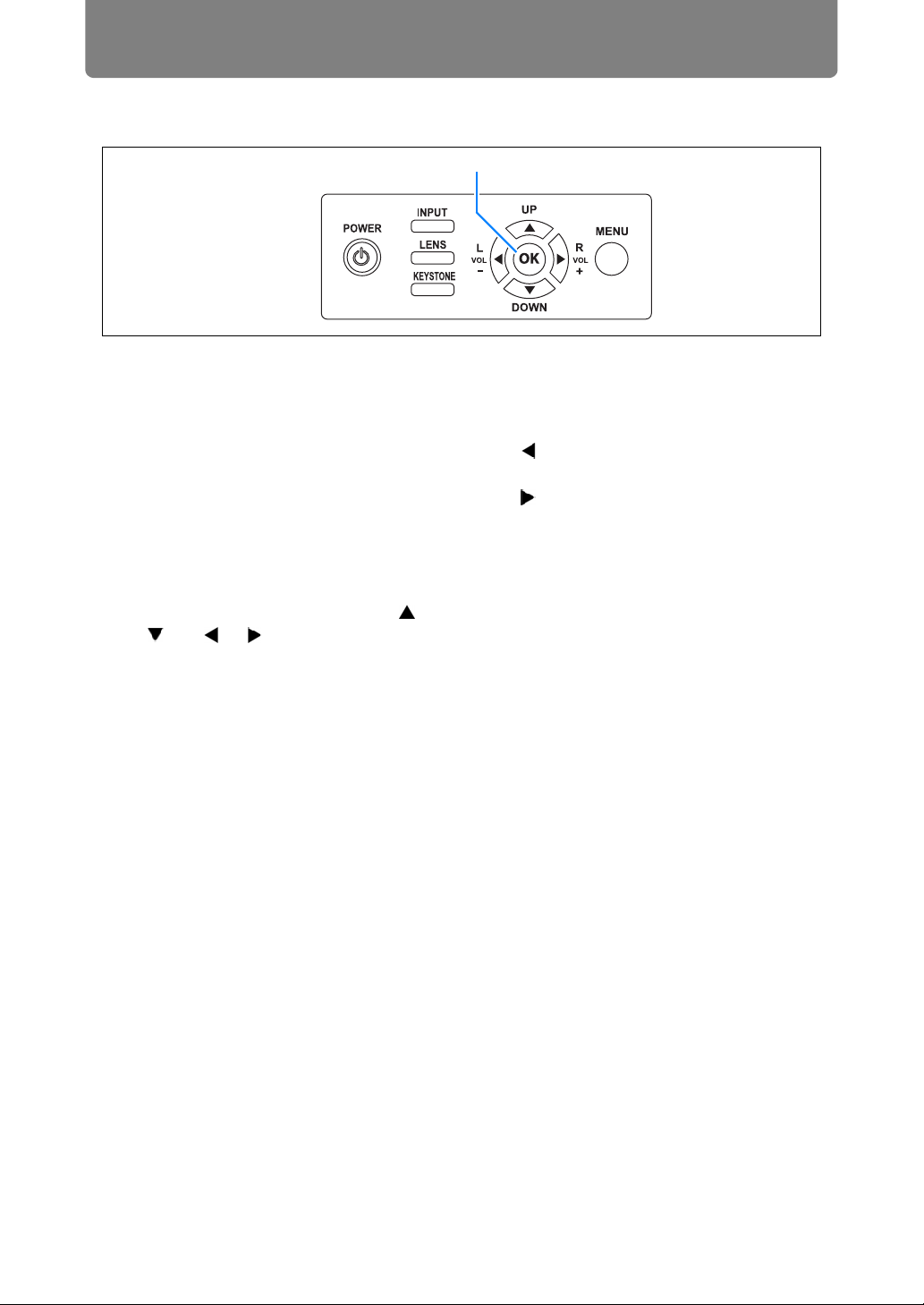
Side Control
(1)
(2)
(3)
(4)
(6)
(5)
(7)
(1) POWER button (P60, P79)
Turns the projector on or off.
(2) INPUT button (P63)
Switches the input signal.
(3) LENS button (P67)
Each time the button is pressed,
the adjustment window changes,
from focus (P67) to zoom (image
size) (P68) to lens shift (image
position) (P70).
To adjust the image, use the [ ] /
[ ] or [ ] / [ ] buttons.
After the focus adjustment window,
the marginal focus adjustment
window is also displayed for
adjusting focus of image edges
(P157), depending on the [Marginal
focus] setting (P102).
(4) KEYSTONE button (P73)
Corrects keystone distortion.
(5) Pointer / VOL buttons (P85)
Up, down, left, or right in menu
navigation or other operations.
Adjust the sound volume.
[ ] VOL– button: Decreases the
volume.
[ ] VOL+ button: Increases the
volume.
(6) OK button (P86)
Determines the item selected from
the menu.
(7) MENU button (P84)
Displays a menu on the screen.
26
Page 27
Before Use
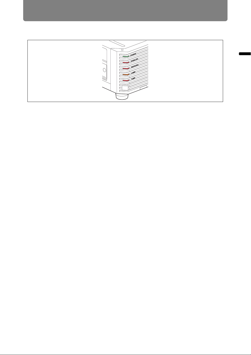
LED Indicators
The projector status is shown by the LED indicators (off / lit / flashing).
• POWER (green) : Lights up or flashes under normal conditions when the
power is on.
• STAND BY (red) : Lights up or flashes during standby or when the projector
is shutting down.
• WARNING (red) : Lights up or flashes when an error occurs.
• LAMP (orange) : Lights up or flashes when a problem occurs with the lamp
or lamp cover.
• TEMP (red) : Lights up or flashes when the internal temperature is
high.
Before Use
27
Page 28
Before Use
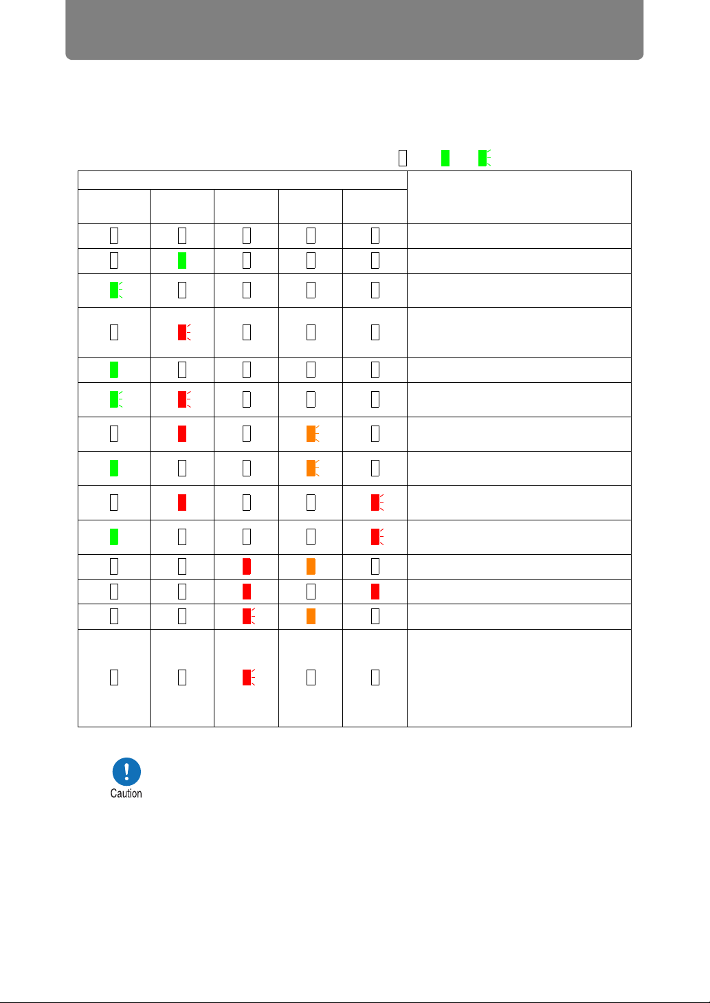
■ LED Indicator Displays
The LED indicators flash or illuminate to indicate the operating status of the
projector.
For details on warnings, see “LED Indicator Details” (P180).
Legend: Example of when the POWER indicator is on; : Off : Lit : Flashing
LED indicator
POWER
(green)
STAND BY
(red)
WARNI NG
(red)
LAMP
(orange)
TEMP
(red)
A projector is not plugged in.
In standby mode.
Resuming operation (projection) after
standby (flashes once).
Cooling down while entering standby
or power management mode from
power on.
Power is on. (Projecting.)
In power management mode, with the
lamp off.
The time for replacing the lamp is
near. (In standby mode.)
The time for replacing the lamp is
near. (During projection)
Internal temperature is high. (In
standby mode.)
Internal temperature is high. (During
projection)
A lamp error has occurred.
Operating status
A temperature error has occurred.
The lamp cover is open.
• An air filter error has occurred
(flashes 3 times).
• A fan error has occurred (flashes
4times).
• A power error has occurred (flashes
5 times).
• A flashing LAMP indicator means that it is almost time to replace
the lamp. Prepare a replacement lamp.
• Lamps that are still used after the timing for lamp replacement are
more likely to rupture. Replace the lamp with a new one as soon
as possible.
28
Page 29
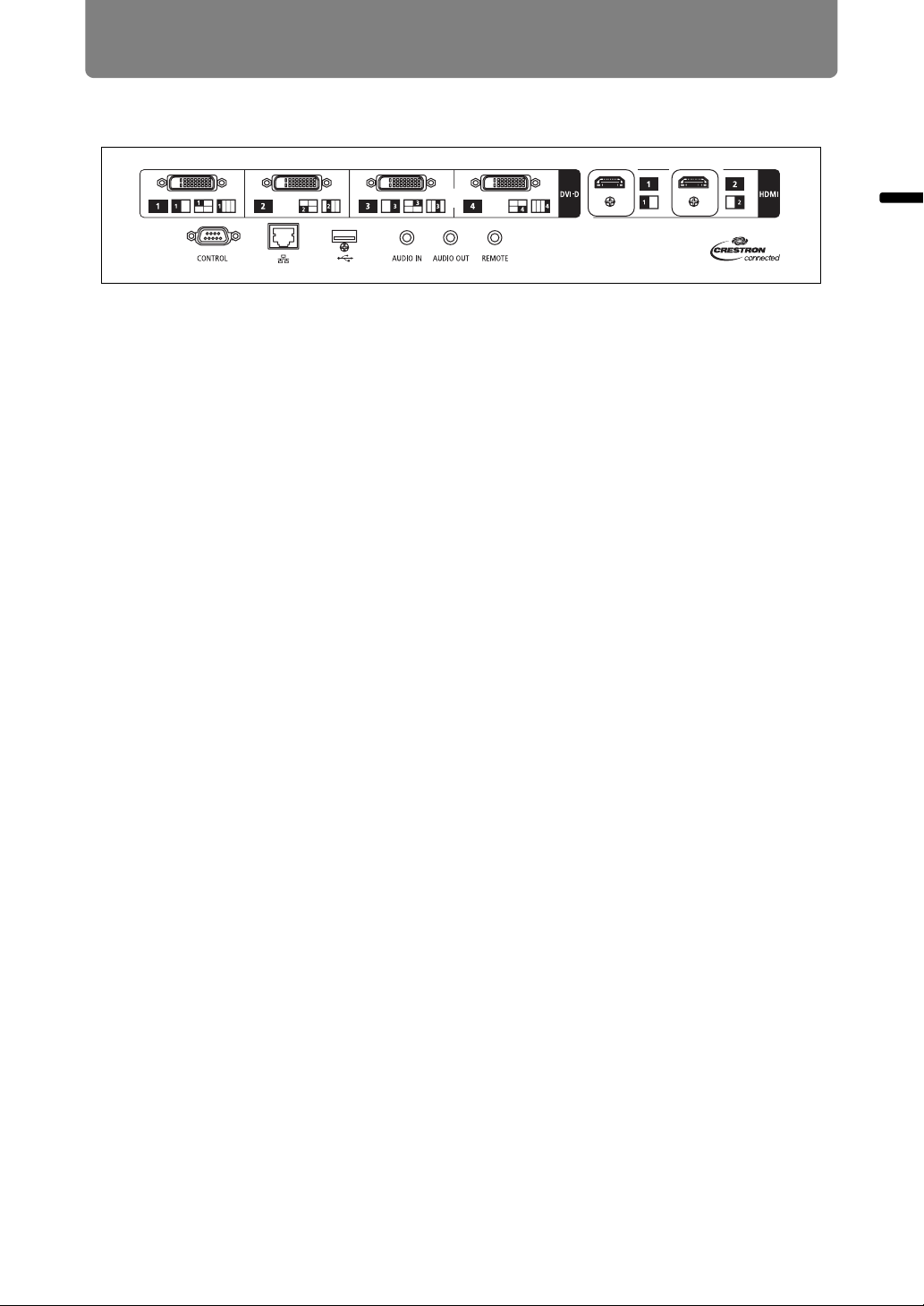
Input Terminal
Before Use
(1)
(3) (4)
(6) (7) (8)(5)
(1) Digital PC / DVI-D terminal (DVI-D) (P53)
Connects the external monitor output from a computer.
Receives digital PC signal (Digital PC).
(2) HDMI terminal (HDMI) (P53, P54)
Receives digital video signals (HDMI).
Carries both video and audio signals across a single cable.
(3) Service port (CONTROL) (P177)
Used for executing user commands (P178 – P179).
(4) LAN port (P122)
Connects the LAN cable (shielded twisted pair).
Used to connect the projector to a network.
(5) USB port (P119)
Connects a USB flash drive. Used for firmware updates.
(2)
Before Use
(6) AUDIO IN terminal (AUDIO IN) (P53, P54)
Receives audio input. Audio supplied to this terminal is played through the
internal speaker when you select [Audio in] as the source audio terminal for
the selected source video.
(7) AUDIO OUT terminal (AUDIO OUT) (P53, P54)
Outputs the audio to external AV equipment. This outputs the audio signal that
corresponds to the projected image signal.
(8) Terminal for wired remote control (REMOTE) (P33)
This terminal is used to connect the remote control using a cable.
29
Page 30
Before Use
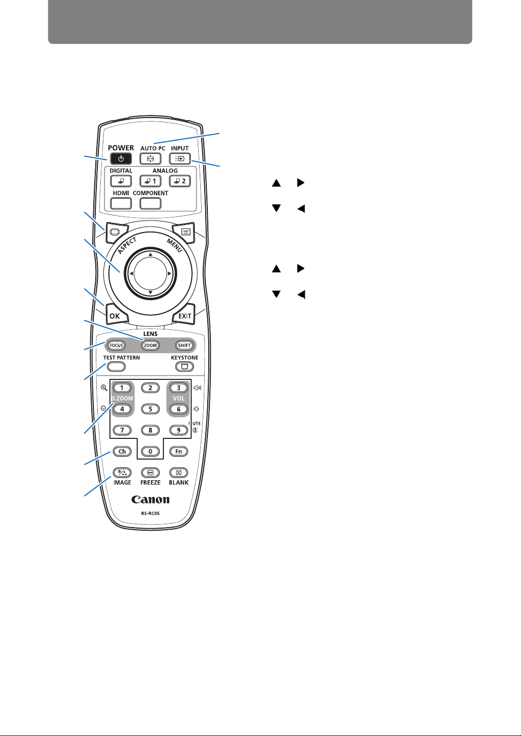
Remote Control
The remote control allows you to operate all functions of the projector.
(4) OK button (P86)
(11)
Determines the item selected from the
menu.
(1)
(12)
(2)
(3)
(4)
(5)
(6)
(7)
(8)
(9)
(10)
(1) POWER button (P60, P79)
Turns the projector on or off.
(2) ASPECT button (P72, P88)
Changes the aspect ratio mode.
(3) Pointer buttons (P85)
Selects the upper, lower, left or right
item in the menu. Also used to assign a
channel to the remote control.
(5) ZOOM button (P68)
Adjusts the image size.
[ ] / [ ] buttons:
Increase the image size.
[ ] / [ ] buttons:
Decrease the image size.
(6) FOCUS button (P67)
Adjusts focusing.
[ ] / [ ] buttons:
Moves the focus position further away.
[ ] / [ ] buttons:
Moves the focus position nearer.
By pressing the FOCUS button twice,
you can also adjust the focus at image
edges (P157), depending on the
[Marginal focus] setting (P102).
(7) TEST PATTERN button (P107)
Displays the test pattern.
(8) D.ZOOM button
Not used with this product.
(9) Ch button (P113)
Changes the remote control channel
when the remote control is used via the
infrared transmitter.
(10) IMAGE button (P76)
Switches the image mode (image
quality).
(11) AUTO PC button
Not used with this product.
(12) INPUT button (P63)
Switches the input signal.
30
Page 31

Before Use
(13) Change input buttons
Change the input signal between Digital
PC and HDMI.
ANALOG 1, ANALOG 2 and
COMPONENT are not used with this
product.
(14) MENU button (P84)
Displays a menu on the screen.
(15) EXIT button (P86)
Cancels functions such as menu
display or test pattern during operation
and returns to the image display.
(16) SHIFT button (P70)
Moves the lens up, down, left or right.
[ ] / [ ] / [ ] / [ ] buttons:
Move the lens.
(17) KEYSTONE button (P73)
Corrects keystone distortion.
The [Keystone] setting enables both
horizontal/vertical keystone correction
(by adjusting top/bottom/left/right
length) and corner correction.
(24) Terminal for wired remote
control (P33)
Connects a cable to the projector for
remote control operation.
Before Use
(13)
(14)
(15)
(16)
(17)
(18) VOL button
Adjusts the sound volume.
[ ] button, [3] button:
Increases the volume.
[ ] button, [6] button:
Decreases the volume.
(19) MUTE button
Mutes the sound.
(20) Numerical buttons (P118, P124,
P126)
Enter password and TCP/IP setting
values.
(21) Fn button
Not used with this product.
(22) BLANK button (P80)
Temporarily blacks out the image.
(23) FREEZE button (P80)
Freezes the projected image.
(18)
(19)
(20)
(21)
(22)
(23)
(24)
31
Page 32

Before Use
Preparing the Remote Control
■ Installing Remote Control Batteries
1 Open the battery
compartment lid.
Raise the battery
cover tab while
pushing it.
• If buttons on the remote control are inoperative when you attempt to operate the
projector, replace the batteries with new ones.
• Do not drop the remote control or subject it to impact.
• Do not spill any liquids on the remote control. Doing so may cause a malfunction.
Pay attention to the following points when handling the batteries.
Failing to do so could result in a fire or personal injury.
• Do not heat, short circuit or disassemble the batteries, or place
them in a fire.
• Do not attempt to recharge the batteries that are included with the
remote control.
2 Insert batteries.
Insert 2 new AA
batteries in the
compartment with the
+ and – terminals
positioned correctly.
3 Close the
compartment lid.
Insert the tab into the
remote control notch
(1) and push the
battery cover down
(2).
(1)
(2)
• Remove the batteries when they are flat or when the remote control
will not be used for a long period of time.
• When replacing the batteries, replace both at the same time. Also,
do not use two batteries of a different type at the same time.
• Insert the batteries with the + and - terminals in the correct
directions.
• If any liquid from inside the batteries leaks out and contacts your
skin, be sure to wash the liquid off thoroughly.
32
Page 33

Before Use
■ Remote Control Operating Range
The remote control is an infrared type. Point it at the infrared remote receiver on the
front or rear of the projector to operate it.
25°
8 m (26.3')
25°
8 m (26.3')
25°
25°
• Use the remote control within an angle of 25° in any direction from directly in front of the
infrared remote receiver.
• The remote control may be inoperative if there is an obstacle between the remote
control and the projector or the infrared remote receiver on the projector is exposed to
direct sunlight or strong light of lighting equipment.
• When you use 2 or more projectors at the same time, you can change the channel
settings to prevent the 2 remote controls from interfering with each other. (P113)
■ Using the Remote (RS-RC05) in a Wired Connection
The remote control can also be used in a wired connection with the projector.
Use a cable with a ø3.5 mm stereo mini jack (not included).
Before Use
Remote control
(RS-RC05)
Terminal for wired
remote control
ø3.5 mm stereo mini jack
cable (not included)
• Infrared operations cannot be performed if a cable is connected to the projector or the
remote control.
• Use a cable with a ø3.5 mm stereo mini jack (not included) with a length of 30 m (98.4')
or less.
33
Page 34

34
Page 35

Safety Instructions
Before Use
Basic Guide
Installation Procedure
Basic Guide
Connection Procedure
Projection Procedure
Convenient Features
Using Menus
Advanced Guide
Menu Settings
Advanced Projection
35
Other Information
Maintenance
Product Specifications
Troubleshooting
Page 36

Installation Procedure
Before setting up the projector, be sure to read “Before Installation” (P18).
Setting Up the Projector
■ Positioning the Projector in Front of the Screen
Place the projector in front of the screen.
• To avoid keystone distortion, install the
projector so that it is at right angles to the
screen.
• The screen must not be exposed to direct
sunlight or light from lighting equipment.
In a bright room, it is recommended that
lights be turned off, curtains be drawn,
and other steps taken to make the screen
easier to see.
Optical axis
Screen
■ Floor Installation
To adjust the projection position when the projector is installed on the floor, use the
lens shift function (P51, P70) to adjust up / down / left / right.
For information about the relationship between screen size and projection distance,
refer to page 50.
Lens shift
36
Page 37

Installation Procedure
■ Installation on High Surfaces
Using the lens shift function (P51), you can project images toward a lower level.
When setting the projector on a high surface for projection, make sure the surface
is flat and stable, and install the projector right-side up with the adjustable feet
facing down.
Failure to do so poses a risk of the
projector falling and causing
accidents or injury.
■ Ceiling Mounting or Rear Projection
You can mount the projector on the ceiling (ceiling mounting) or place it behind the
screen (rear projection) if you use a translucent screen.
Basic Guide Installation Procedure
Ceiling mounting
Remove the caps on top of the projector before installing a ceiling attachment.
When mounting the projector on the ceiling, it is more convenient to install the projector
right-side up, with the adjustable feet facing down.
37
Rear projection
Page 38

Installation Procedure
Ceiling Mounting
Ceiling Attachment Part No.: RS-CL15 (Option)
Make sure the followings when you install and handle the ceiling attachment. Otherwise, it
may result in fire, electric shock or injury.
• Make sure to prepare stable scaffolding when installing the ceiling
attachment.
• Make sure to fully insert the power plug and connectors when
connecting the projector. Never use a damaged plug or loosen
outlet.
• Make sure to tighten screws for the ceiling attachment securely
and never loosen or remove them.
• Never look into a lens when adjusting the projection because a
high-intensity light is projected from the projector. It may result in
eye damage.
• During projection, never put an object in front of the projector’s
lens.
Make sure the followings when you install and handle the ceiling attachment.
• Make sure to ask the Canon Customer Support Center if you want
to install the ceiling attachment. An inappropriate installation may
cause an accident.
38
Page 39

Parts Lineup
Installation Procedure
■ Parts Included with RS-CL15
Weight: RS-CL15 (6.9 kg/15.2 lbs)
• Ceiling-mount bracket and Joint fitting • Base bracket
Ceiling-mount
bracket
Joint fitting
The Ceiling-mount bracket must be
separated from the Joint fitting, before
installation.
• Template sheet for a ceiling-mount hole: 2 shts.
B 4K500STA
Basic Guide Installation Procedure
Use the template sheet (B) for
the projector.
• M6 screw (25 mm/1.0") : 4 pcs. • M4 screw (15 mm/0.6") : 10 pcs.
• Anti-fall wires: 2 pcs. • Washer (Toothed Lock Washer): 1 pc.
• M5 screw (12 mm/0.5") with washer: 4 pcs.
• Assembly/Installation Manual
(this manual): 1
39
Page 40

Installation Procedure
■ Extension pipe RS-CL08 / RS-CL09 (option)
Weight: RS-CL08 (2.2 kg/4.9 lbs)/RS-CL09 (3.4 kg/7.5 lbs)
Use an optional extension pipe (RS-CL08 / RS-CL09) according to the ceiling
height. For details, contact our local agent.
RS-CL08
Outer/inner pipes and outer/inner covers
M5 screw (12 mm/0.5") : 4 pcs.
M3 screw (10 mm/0.4") : 1 pc.
* The length is adjustable between 35 cm/1.1'
and 55 cm/1.9' in steps of 5 cm/0.2'.
RS-CL09
Outer/inner pipes and outer/inner covers
M5 screw (12 mm/0.5") : 4 pcs.
M3 screw (10 mm/0.4") : 1 pc.
* The length is adjustable between 55 cm/1.9'
and 95 cm/3.1' in steps of 5 cm/0.2'.
x 4
x 4
Mounting Position
Install the projector straight in front of the screen. You can adjust the screen
position using the lens shift feature.
• Before mounting the Ceiling Attachment, be sure to check the
strength of the ceiling. The ceiling should be strong enough to
support the projector and Ceiling Attachment (and optional
extension pipe). If the ceiling is not strong enough, be sure to
reinforce it. The projector may fall and you may get injured.
• Make sure to perform the installation operation by at least two
persons. Please be careful not to drop any object and pinch a
finger during the installation operation.
• To prevent falling caused by earthquake or vibration, take anti-fall
measures using tension wires or the like for installation. The
projector may fall and you may get injured.
• At least 50 cm (1.6') around the intake and 50 cm (1.6') around the
vent should be clear. Otherwise, it may damage the projector due
to bad exhaust ventilation.
40
Page 41

Installation Dimensions
Installation Procedure
Projection
Distance
Height
298 mm
(11.7")
534 mm (21.0")
236 mm
(9.3")
Side view
113 mm
(4.4")
279 mm
(11.0")
263 mm
(10.4")
236 mm
(9.3")
227 mm
(8.9")
Top view
Distance from ceiling to lens center ( )
RS-CL15 When RS-CL08 is used When RS-CL09 is used
22.9 cm (9.0")
57.9 cm (22.8") to
77.9 cm (30.7")
100 mm
230 mm
(9.1")
230 mm
(9.1")
(3.9")
113 mm
(4.4")
470 mm (18.5")
Front view
235 mm
(9.3")
235 mm
(9.3")
77.9 cm (30.7") to
117.9 cm (46.4")
Basic Guide Installation Procedure
Ceiling-mount bracket
100 mm
100 mm
(3.9")
(3.9")
(3.1")
80 mm
(3.1")
80 mm
80 mm
80 mm
(3.1")
(3.1")
(3.9")
100 mm
(3.9")
100 mm
41
Page 42

Installation Procedure
Assembly and Installation
■ Installation to flat and level Ceiling
Preparation: Separate the Joint
fitting from the Ceiling-mount
bracket temporarily
Remove four M5 screws to separate Joint
fitting from the Ceiling-mount bracket.
1 Make a hole in the ceiling
• Use the template sheet (B) to make
holes in the ceiling for securing the
Ceiling-mount bracket.
• Make holes to thread cables
through.
• Always use the included template sheet (B) to determine where to
make holes.
• The template sheet (B) is labeled with the direction to the screen, as
well as the optical axis (center of the lens).
Direction to the
screen
2 Secure the Ceiling-mount
bracket to the ceiling
Use four M13 screws, to secure the
Ceiling-mount bracket to the ceiling
with the arrow facing toward the
screen.
• Before securing the Ceiling-
mount bracket, be sure to remove
the template sheet (B).
• The M13 screws are not included
in the supplied parts. Prepare the
M13 screws suitable for the
ceiling structure.
Direction to the
screen
42
Page 43

Installation Procedure
3 Attach the Base bracket to the
projector
1 Remove the four screws at each
corner on top of the projector.
2 Install the attached M6 screws at
the four screw fastening
positions on the Base bracket.
Attach the included toothed lock
washer in the back-left position,
as shown at right.
4 Attach the anti-fall wire
Secure the terminal clamp with the
attached M4 screw at (A) on the
Base bracket.
• Make sure to fasten and tighten
the screw securely.
5 Pull cables out of the cable hole
in the ceiling
• As depicted in the diagram, let
cables pass through the hole on
ceiling-mount clamp.
• If cables are too thick, make a
hole at a different position than
the hole on the ceiling-mount
clamp, and let them pass through
the new hole.
Washer (Toothed Lock Washer)
Basic Guide Installation Procedure
A
6 Attach the Joint fitting to the
Ceiling-mount bracket
Secure the Ceiling-mount bracket
using the four M5 screws removed
during preparation.
Direction to the screen
43
Page 44

Installation Procedure
7 Hook the Base bracket to the
Joint fitting and secure it
temporarily
Hook the Base bracket on the
protrusion (A) of the Joint fitting,
and secure it temporarily using the
four supplied M5 screws (B).
• Pull out the cables.
• Be sure to secure screws (B)
tightly after making the
adjustment discussed in “Adjust
the Projection Angle” (P48).
B
A
8 Connect cables
Connect cables to the projector.
After completion of installation, adjust the projection angle (P48).
B
44
Page 45

Installation Procedure
■ Installation to a High Ceiling
Use optional extension pipe RS-CL08 or RS-CL09 for high ceiling.
Preparation: Adjust the pipe length
according to the ceiling height
1 Remove the covers of outer and inner pipes by
slightly sliding them and lift up as shown.
2 Remove four M5 screws from the sides of the
outer pipe, adjust the inner pipe length
according to the projector installation height,
and then secure the four M5 screws.
• When attaching screws in step 2, insert the
screws and leave an unused screw hole
between them. When the extension pipe is
stretched to its maximum length, insert the
screws in two adjacent screw holes.
Extended length when extension pipe is attached (when lens shift is 0%)
1
Basic Guide Installation Procedure
2
Mounting hole
position
a 57.9 cm (22.8") 77.9 cm (30.7")
b 62.9 cm (24.8") 82.9 cm (32.6")
c 67.9 cm (26.7") 87.9 cm (34.6")
d 72.9 cm (28.7") 92.9 cm (36.6")
e 77.9 cm (30.7") 97.9 cm (38.5")
f 102.9 cm (40.5")
g 107.9 cm (42.5")
h 112.9 cm (44.4")
i 117.9 cm (46.4")
Distance from ceiling to lens axis ( )
RS-CL08 RS-CL09
b
d
f
h
'
a
c
e
g
i
1 Separate the Joint fitting from the Ceiling-mount bracket temporarily
(Preparation on page 42)
2 Make a hole in the ceiling (Step 1 on page 42)
3 Secure the Ceiling-mount bracket to the ceiling (Step 2 on page 42)
4 Attach the Base bracket to the projector (Step 3 on page 43)
5 Attach the anti-fall wire (Step 4 on page 43)
45
Page 46

Installation Procedure
6 Attach the top of the extension
pipe to the Ceiling-mount
bracket
Secure to the extension pipe using
the four supplied M5 screws.
• The open end of the pipe should
face the open end of the Ceilingmount bracket as shown.
Direction to the
screen
7 Attach the Joint fitting to the
bottom of the extension pipe
Use the four M5 screws removed
from the Ceiling-mount bracket
during preparation.
Direction to the
screen
46
Direction to the screen
Page 47

Installation Procedure
8 Hook the Base bracket to the
Joint fitting and secure it
temporarily
Hook the Base bracket on the
protrusion (A) of the Joint fitting,
and secure it temporarily using the
four supplied M5 screws (B).
• Pull out the cables.
• Be sure to secure screws (B)
tightly after making the
adjustment discussed in “Adjust
the Projection Angle” (P48).
9 Put the cables in to the pipe and
attach the covers
Thread any cables that are too
thick for the ceiling-mount bracket
hole through a separate hole you
have opened.
1 Pull the cables out of the cable
hole in the ceiling.
2 Put the cables inside the pipe.
3 Close the inner cover of the pipe
and then close outer cover of the
pipe.
Secure to the extension pipe
using the supplied M3 screw.
4 Connect the cables to the
projector.
A
Basic Guide Installation Procedure
B
B
47
Page 48

Installation Procedure
Adjust the Projection Angle
Turn on the projector, project an image, and then adjust the projection angle and
screen slant angle.
• After completion of adjustment, tighten the screws and check that
every fitting is secured firmly.
• Be sure to hold the projector from falling until the Ceiling-mount
bracket and Base bracket are secured firmly.
Adjust the horizontal
projection angle.
A
Adjust the vertical
projection angle.
B
C
■ Adjust the horizontal projection angle
1 Loosen two wing screws (A). Move
the projector horizontally to adjust
the horizontal projection angle.
2 When the projector is correctly
positioned, tighten the wing screws.
■ Adjust the vertical projection angle
1 First loosen four screws (B) and then
loosen two wing screws (C). Move
the projector vertically to adjust the
vertical projection angle.
2 When the projector is correctly
positioned, first tighten the wing
screws (C) and next tighten the four
screws (B).
Adjust the screen
slant angle.
D
5q
5q
5°
20°
48
Page 49

■ Adjust the screen inclination
5°
5°
1 Loosen four screws (D), and then
adjust the slant angle of the
projector.
2 When the projector is correctly
positioned, tighten the four screws
(D).
Precautions when replacing lamps that stop working
• If illumination suddenly stops, either when you turn the projector
on or after it has been on for a while, the lamp may have ruptured.
In this case, never attempt to replace the lamp by yourself. Always
request service from the Canon Customer Support Center.
• With ceiling-mounted projectors, the lamp may fall out when you
open the lamp cover, or during replacement. During replacement,
stand to the side of the lamp cover, not directly under it.
• If the lamp ruptures, dust and gas (containing mercury vapor) may
come out of the exhaust vents. If this happens, immediately open
the windows and doors to provide ventilation to the room.
• If you accidentally inhale gas from the lamp or get any pieces in
your eyes or mouth, consult a doctor immediately.
Installation Procedure
5°
5°
Basic Guide Installation Procedure
49
Page 50

Installation Procedure
Relationship between Projecting Distance and Image Size
The projected image size is determined by the distance to the screen (projection
distance), the size of the image (P68), and the level of focus (P67). Refer to the
following table and decide the distance between the projector and screen.
Image Size (diagonal)
Height
Width
4K500ST
Image Size
(Dia.)
40 90 (35.4) 47 (18.5) 88 (34.6) 51 (20.1) 0.9 (3.0) 1.1 (3.6)
60 135 (53.1) 71 (28.0) 131 (51.6) 77 (30.3) 1.3 (4.3) 1.7 (5.6)
80 180 (70.9) 95 (37.4) 175 (68.9) 103 (40.6) 1.8 (5.9) 2.3 (7.5)
100 225 (88.6) 118 (46.5) 219 (86.2) 128 (50.4) 2.2 (7.2) 2.9 (9.5)
120 270 (106.3) 142 (55.9) 263 (103.5) 154 (60.6) 2.7 (8.9) 3.5 (11.5)
140 315 (124.0) 166 (65.4) 307 (120.9) 180 (70.9) 3.1 (10.2) 4.1 (13.5)
160 359 (141.3) 190 (74.8) 351 (138.2) 205 (80.7) 3.6 (11.8) 4.7 (15.4)
180 404 (159.1) 213 (83.9) 394 (155.1) 231 (90.9) 4.0 (13.1) 5.3 (17.4)
200 449 (176.8) 237 (93.3) 438 (172.4) 257 (101.2) 4.5 (14.7) 5.8 (19.0)
220 494 (194.5) 261 (102.8) 482 (189.8) 282 (111.0) 4.9 (16.1) 6.4 (21.0)
240 539 (212.2) 284 (111.8) 526 (207.1) 308 (121.3) 5.4 (17.7) 7.0 (23.0)
260 584 (229.9) 308 (121.3) 570 (224.4) 334 (131.5) 5.9 (19.4) 7.6 (24.9)
280 629 (247.6) 332 (130.7) 614 (241.7) 360 (141.7) 6.3 (20.7) 8.2 (26.9)
300 674 (265.4) 355 (139.8) 657 (258.7) 385 (151.9) 6.8 (22.3) 8.8 (28.9)
350 786 (309.4) 415 (163.4) 767 (302.0) 449 (176.8) 7.9 (25.9) 10.3 (33.8)
400 899 (353.9) 474 (186.6) 877 (345.3) 514 (202.4) 9.0 (29.5) 11.8 (38.7)
450 1011 (398.0) 533 (209.8) 986 (388.2) 578 (227.6) 10.2 (33.5) 13.2 (43.3)
500 1123 (442.1) 592 (233.1) 1096 (431.5) 642 (252.8) 11.3 (37.1) 14.7 (48.2)
550 1236 (497.2) 652 (256.7) 1205 (474.4) 706 (278.0) 12.4 (40.7) 16.2 (53.1)
600 1348 (530.7) 711 (279.9) 1315 (517.7) 770 (303.1) 13.6 (45.3) 17.7 (58.1)
4096 x 2160 4096 x 2400
Width
[cm (in)]
Height
[cm (in)]
Width
[cm (in)]
Height
[cm (in)]
Projection distance
[m (feet)]
Wide limit Tele limit
50
Page 51

Lens Shift Function
Installation Procedure
You can reposition the image in all directions by pressing the SHIFT button on the
remote control, which moves the lens up, down, left, or right. For instructions, refer
to “Adjusting the Image Position” (P70).
■ Amount of Lens Shift
The amount of lens shift is indicated as a percentage relative to the image height
and width. The lens shift ranges for the projector are as follows.
A (Amount of vertical shift) ±60%
B (Amount of horizontal shift) ±10%
The lens can be shifted up or down and to the left or right. Performance using lens
shift is ensured within the recommended range described below. However,
peripheral dimness or blurriness may occur in the corners outside the last 10% of
the horizontal lens shift range and outside the last 15% of the vertical lens shift
range. In this case, adjust lens shift to within the recommended range.
Recommended lens shift range
A
B
10%
15%
A
Basic Guide Installation Procedure
Recommended lens shift
range
A
Lens shift range
Amount of lens shift:
up/down 60%
51
A
Page 52

Installation Procedure
4K500ST
Maximum vertical (A) and horizontal (B) movement using lens shift
Image size (Dia.)
40 31 (12.2) 9 (3.5) 28 (11.0) 9 (3.5)
60 46 (18.1) 13 (5.1) 43 (16.9) 13 (5.1)
80 62 (24.4) 18 (7.1) 57 (22.4) 18 (7.1)
100 77 (30.3) 22 (8.7) 71 (28.0) 22 (8.7)
120 92 (36.2) 26 (10.2) 85 (33.5) 27 (10.6)
140 108 (42.5) 31 (12.2) 100 (39.4) 31 (12.2)
160 123 (48.4) 35 (13.8) 114 (44.9) 36 (14.2)
180 139 (54.7) 39 (15.4) 128 (50.4) 40 (15.7)
200 154 (60.6) 44 (17.3) 142 (55.9) 45 (17.7)
220 169 (66.5) 48 (18.9) 156 (116.9) 49 (19.3)
240 185 (72.8) 53 (20.9) 171 (67.3) 54 (21.3)
260 200 (78.7) 57 (22.4) 185 (72.4) 58 (22.8)
280 216 (85.0) 61 (24.0) 199 (78.3) 63 (24.8)
300 231 (90.9) 66 (26.0) 213 (83.9) 67 (26.4)
350 269 (105.9) 77 (30.3) 249 (98.0) 79 (31.1)
400 308 (121.3) 88 (34.7) 284 (111.8) 90 (35.4)
450 347 (136.6) 99 (39.0) 320 (126.0) 101 (39.8)
500 385 (151.6) 110 (43.3) 355 (139.8) 112 (44.1)
550 424 (166.9) 121 (47.6) 391 (153.9) 124 (48.8)
600 462 (181.9) 132 (52.0) 427 (168.1) 135 (53.1)
(reference values [cm (in)])
4096 x 2400 4096 x 2160
ABAB
• (A) values are the approximate vertical lens shift distance from the central image
position within the supported lens shift range.
• (B) values are the approximate horizontal lens shift distance from the central image
position within the supported lens shift range.
• Watch projected images as you perform lens shift adjustment.
• When the image no longer moves, you have reached the limit of the lens shift range.
52
Page 53

Connection Procedure
Before connecting the projector to other equipment, turn off both the projector
and the other equipment.
For instructions on connecting multiple sources of input for 4K projection, refer to “Multi
Input 4K Projection” (P55).
Connecting a Computer
Basic Guide Connection Procedure
Computer
AUDIO output
terminal
Audio cable
(not included)
DVI-D terminal
AUDIO IN terminal
Monitor output
(DVI-D terminal)
DVI-D cable
(not included)
terminal
HDMI cable
(not included)
AUDIO OUT
terminal
HDMI
terminal
HDMI
terminal
Audio cable
(not included)
Mini jack RCA terminal
Amplified
speakers
Audio cable
(not included)
53
Page 54

Connection Procedure
Connecting AV Equipment
Amplified
speakers
Mini jack RCA terminal
Audio cable
(not included)
HDMI cable
(not included)
Audio cable
(not included)
AUDIO OUT
terminal
HDMI
terminal
HDMI terminal
AV equipment
54
Page 55

Connection Procedure
Multi Input 4K Projection
■ Definition of 4K
4K refers to high-resolution video with a horizontal resolution of about 4,000 pixels,
which is four times the resolution of full HD (1920 x 1080).
Although 4K is a convenient description, it encompasses several different
resolutions, such as 3840 x 2160, 3840 x 2400, 4096 x 2160, and 4096 x 2400.
(4096 x 2160 is also referred to as Ultra HD, and 3840 x 2400 as WQUXGA.)
The projector supports resolutions up to 4096 x 2400. For details, check the table of
supported signals. (P169)
1920 x 1080
3840 x 2160
4096 x 2400
■ 4K Support Using Digital Signals and Multiple Inputs
The projector is equipped with DVI-D and HDMI (1.4) inputs for digital signals.
However, these signals cannot be used as-is for 4K projection.
DVI-D is classified as single-link or dual-link, depending on the dot clock. Projecting
resolutions with a dot clock higher than 165 MHz requires a dual-link plug and
cable.
The following resolutions are supported.
• 1920 x 1200 (single-link; vertical frequency: 60 Hz)
• 2560 x 1600 (dual-link; vertical frequency: 60 Hz)
• 4096 x 2160 (dual-link; vertical frequency: 24 Hz)
However, most current computers are limited to a
maximum DVI-D output resolution of 2560 x 1600.
For HDMI 1.4, the following resolutions are supported.
• 1920 x 1080 (vertical frequency: 60 Hz)
• 3840 x 2160 (vertical frequency: 24 Hz / 25 Hz / 30 Hz)
• 4096 x 2160 (vertical frequency: 24 Hz)
To avoid the limitation with DVI-D that a single signal line cannot carry video with a
resolution of 4096 x 2400 (vertical frequency: 60 Hz) even with a dual-link cable,
the projector enables you to project multiple lines of input at once. This feature is
called Multi Input mode.
Single-link plug
Dual-link plug
Basic Guide Connection Procedure
Number of dual-link cables 1 4
Compatible video signals
4096 x 2160
(vertical frequency: 24 Hz)
55
4096 x 2400
(vertical frequency: 60 Hz)
Page 56

Connection Procedure
■ Connections for Multi Input Mode
Multi Input mode requires that the computer’s video output (whether dual-link
compatible DVI-D or HDMI) support split-screen display or display in four
quadrants. To connect the projector to computers, use up to four DVI cables and
two HDMI cables.
Refer to the following figure.
Connect up to four dual-link DVI-D cables
Connect workstations by using four dual-link DVI cables
Connect up to two HDMI cables
Connect desktop computers by using two HDMI cables
Connect up to one HDMI cable
Connect notebook computers by using one HDMI cable
You cannot project on two or four screens when the projector is connected to multiple
computers or pieces of AV equipment.
56
Page 57

Connection Procedure
■ Settings for Multi Input Mode
Select how to combine four DVI inputs or two HDMI inputs to form an image. Check
computer video output settings in advance, because you must match the display
layout (whether split-screen display or display in four quadrants).
Multi Input Mode
Specify the type of image (including resolution) supplied to the terminals. Use [Normal] for
most signals. For specific signals, use [Single], [1x2], [2x2], or [1x4] as needed. For
details, check the table of supported signals. (P169)
• [Normal] setting
Supports many typical images, including [Single], [1x2], [2x2], and [1x4].
• [Single] setting
Supports many specialized signals from a single piece of connected equipment.
• [1x2] setting
Supports many specialized signals when two signals are supplied.
• [2x2] setting
Supports many specialized signals when four signals are supplied, for projection in a
2x2 layout.
• [1x4] setting
Supports many specialized signals when four signals are supplied, for projection side
by side.
Basic Guide Connection Procedure
1 In the [Install settings] menu, select [Professional settings] > [Multi input
mode select].
2 Select the input mode to use.
57
Page 58

Connection Procedure
DVI input mode
Specify the combination of DVI input. Choose from [Normal], [Single], or [1x2],
[2x2], or [1x4].
• Normal
• Single
• DVI 1x2
• DVI 2x2
• DVI 1x4
HDMI input mode
Specify the combination of HDMI input. Choose from [Normal], [Single], or
[1x2].
• Normal
• Single
• HDMI 1x2
These examples show projection in the case of [1x2], [2x2], and [1x4].
1x2 (HDMI)
1x2 (DVI)
1312
2x2 (DVI) 1x4 (DVI)
13
1234
24
When this setting is set to [Normal], the EDID (unique ID that conveys to computers
the model name and setting values of connected display devices) is a list that
consists of video signals used with one or multiple projector terminals. On the video
output equipment, you can specify video signals for use with a different number of
terminals.
[Multi input mode select] window is displayed automatically if the input terminals do not
match the settings configured by using the INPUT button.
58
Page 59

Connection Procedure
■ 4K Projection Notes
Colors may appear distorted when images are viewed from the side on some
screens, but this does not indicate a problem with the projector. For best results,
use a matte screen with a wide viewing angle.
Plugging the Projector In
Connect the power cord to the projector and plug it in.
• Be sure to connect the ground wire of the power cord to ground.
• Be sure to connect the ground wire before connecting the power plug
to the outlet. Also when you disconnect the ground wire, be sure to
unplug the power plug from the outlet beforehand.
Basic Guide Connection Procedure
• Fully insert the power cord plug into the socket.
• After turning off the projector, wait at least 5 minutes before turning it on again. Turning
the projector on immediately after turning it off may shorten the lamp life.
• Unplug the power cord when the projector is not in use.
59
Page 60

Projection Procedure
Step 1 Turn the Projector On
1 Check the connection between the projector and the computer or AV
equipment. (P53, P54)
For instructions on connecting the power cord, refer to “Plugging the Projector
In” (P59).
2 Press the POWER button.
The [POWER] indicator initially flashes green, after which it remains lit.
Remote control Projector
The countdown window is displayed for approximately 20 seconds, and then
the projection is started. Press the OK or EXIT button to hide the countdown
window.
• Network functions are not available until about 40 seconds after you plug the projector
in.
• Some noise may appear in the projected image during the first few minutes, until the
image stabilizes.
• A window appears when the projector is turned on for the first time. You can select a
language to be used by the projector for displaying menus and messages in the
window. Select the desired language with the pointer buttons and press the OK button.
(P61)
You can change the language from the menu at a later time. (P116)
3 Turn on the computer or AV equipment power.
Images from the computer or AV equipment are now projected.
Changing Operations When Projector is Turned On
You can change operations when the projector is turned on as follows.
• You can turn on the projector by connecting the power cord, without
pressing the POWER button. (P115)
• You can change the countdown window. (P109)
• You can skip the countdown window. (P109)
When the Projector Is Left Idle
If no signal is received, the power management feature automatically turns off
the projector after a certain period of inactivity (by default, 15 minutes). (P114)
60
Page 61

Projection Procedure
■ When the Language Selection Screen Appears
A screen appears when the projector is turned on for the first time. You can select a
language to be used by the projector for displaying menus and messages in the
window. Select the desired language with the pointer buttons and press the OK
button.
You can change the language from the menu at a later time. (P116)
If the language selection screen is out of focus, adjust the focus. (P67
Remote control Projector
An item highlighted in orange will be selected.
)
■ When the Password Input Screen Appears
If you have set a password, the password input screen appears. Enter your
password. (P117)
Basic Guide Projection Procedure
■ When “No signal” Appears
With a notebook computer, the user must turn on the external monitor output. (P62)
Press the INPUT button to select the input signal. (P63)
■ When Notebook Computer Screen Does Not Appear
Set your notebook computer to output signals to an external monitor. For more
details, refer to “Changing Notebook Computer Screen Output” (P62).
■ Adjusting Image
• Set the display resolution of the computer to the highest resolution or the
resolution closest to that setting. (P65)
• Use the ZOOM button on the remote control to resize the projected image. (P68)
• If the image is blurry, use the FOCUS button on the remote control to adjust focus.
(P67)
• Correct any keystone distortion by pressing the KEYSTONE button. (P73)
• Select a screen mode (aspect) according to the aspect ratio of the screen, type of
input image signal etc. (P72)
• Select an image mode depending on the projected image. (P76)
The image can also be adjusted by projecting a test pattern (P168).
61
Page 62

Projection Procedure
Changing Notebook Computer Screen Output
For projection from a notebook computer, the computer settings must be adjusted
to switch display output.
This operation is not required for a desktop computer.
■ Turning on External Monitor Output
You can turn on the external monitor output via keyboard operation.
To turn on the external monitor output with most computers, press the function key
([F1] to [F12]) which is marked with the external monitor icon while holding down
the [Fn] key.
While pressing key
• The function key you use and the method used to turn on the external monitor output
vary depending on the model. For details, see the manual for your notebook computer.
• With Windows 8.1, Windows 8 or Windows 7, you can turn on image output by holding
down the Windows logo key and pressing the [P] key.
press a key such as or .
62
Page 63

Projection Procedure
Step 2 Select an Input Signal
Select the input signal in the [Input] menu when you want to project a digital PC or
AV equipment signal, or to switch between inputs when multiple computers or
multiple sets of AV equipment are connected.
Skip this step if you have not changed the input signal since the last projection.
1 Press the INPUT button to display the window shown below.
Remote control Projector
Basic Guide Projection Procedure
The currently active input signal is marked with a green circle and enclosed by
a orange border.
Names of input signals available for projection are displayed in white, and
unavailable signal names are grayed out.
2 Press the [ ] / [ ] buttons to select the input signal.
You can also switch from one DVI-D input source to the next by pressing the
DIGITAL button, or from one HDMI input source to the next by pressing the
HDMI button.
3 Press the OK button to confirm the input signal type.
63
Page 64

Projection Procedure
• You can also switch to your preferred input signal for projection by pressing buttons on
the remote control to switch input signals (specifically, the DIGITAL or HDMI button).
• In multi input mode, the projector combines two or four sources of input for projection
together. As sources of input for projection at 4K or other resolutions, choose from [DVI
1x2], [DVI 2x2], [DVI 1x4], or [HDMI 1x2]. (P55)
• Signals you supply for Multi Input mode must meet certain conditions. If the signals do
not meet these requirements, a [ ! ] icon is displayed.
64
Page 65

Projection Procedure
Step 3 Adjust the Image
Setting the Display Resolution of the Computer
Based on the maximum resolution of the projector, set the display resolution of the
computer to the resolution closest to the output signal resolution of the projector.
(P169)
Maximum resolution
• 4096 x 2160: When [Panel drive mode] is set to [4096x2160].
• 4096 x 2400: When [Panel drive mode] is set to [4096x2400].
■ Windows 8.1 / Windows 8
1 Move the cursor toward the upper or lower right corner to access the
menu.
2 Click [Settings], and then click [Control Panel].
3 From [Control Panel Home] - [Appearance and Personalization], select
[Adjust screen resolution].
4 Click the [Resolution] tab, and move the slider to select the resolution
closest to the maximum output signal resolution of the projector.
5 Click the [OK] button.
■ Windows 7
1 Open the [Control Panel] from the start menu, then select [Appearance
and Personalization] - [Adjust screen resolution] in the [Control Panel
Home].
Basic Guide Projection Procedure
2 Click the [Resolution] tab, and move the slider to select the resolution
closest to the maximum output signal resolution of the projector.
3 Click the [OK] button.
65
Page 66

Projection Procedure
■ Windows Vista
1 Open the [Control Panel] from the start menu, then select [Appearance
and Personalization] - [Adjust screen resolution] in the [Control Panel
Home].
2 Select the resolution closest to the maximum output signal resolution of
the projector from the [Resolution] list.
3 Click the [OK] button.
■ Mac OS X
1 Open the Apple Menu and select [System Preferences].
2 In the [System Preferences] window, click the [Displays] icon to display
the Display window.
3 Select the [Display] tab and select the resolution closest to the maximum
output signal resolution of the projector from the [Resolutions] list.
4 Close the [System Preferences] window.
66
Page 67

Projection Procedure
Focusing, Resizing, or Moving the Image
■ Adjusting Image Focus
To adjust the focus, press the FOCUS button on the remote control or the LENS
button on the projector.
1 Press either the FOCUS button on the remote control or the LENS button
on the projector to display the focus adjustment window.
Remote control Projector
2 Press the pointer buttons to adjust the focus.
Remote control Projector
Basic Guide Projection Procedure
To adjust the focus, use the [ ] / [ ] button on the remote control or projector.
3 When the focus is adjusted optimally, press the OK button or the FOCUS
button.
If the screen is curved, you can adjust the focus of the image edges. Refer to “Marginal
focus” (P102) and “Adjusting Peripheral Focus” (P157).
67
Page 68

Projection Procedure
■ Adjusting Image Size
The size of the projected image can be adjusted by pressing the ZOOM button on
the remote control or the LENS button on the projector. Change the projector
installation position if your desired image is too large or too small to adjust it with
the zoom function. (P36)
1 Press the ZOOM button on the remote control to display the zoom
adjustment window.
Remote control
Press the LENS button on the projector repeatedly to switch between windows
for parameters adjusted by controlling the lens.
To access the zoom adjustment window, press the LENS button twice (or three
times if you have set [Marginal focus] to [On]).
Projector
Press twice.
When [Marginal focus]
is set to [On].
When [Marginal
focus] is set to [Off].
68
Page 69

Projection Procedure
2 Press the pointer buttons to adjust the image size.
Remote control
To enlarge the image, use the [ ] button on the remote control or projector.
To reduce the image, use the [ ] button on the remote control or projector.
Projector
Screen
3 When the desired image size is selected, press the OK button or the
ZOOM button.
Basic Guide Projection Procedure
69
Page 70

Projection Procedure
■ Adjusting the Image Position
To adjust the screen position up, down, left, or right, press the SHIFT button on the
remote control or the LENS button on the projector. It can change the projected
screen to the most suitable position by moving the position of the lens up/down/left/
right. (P51)
1 Press the SHIFT button on the remote control to display the lens shift
adjustment window.
Remote control
Press the LENS button on the projector repeatedly to switch between windows
for parameters adjusted by controlling the lens.
To access the lens shift adjustment window, press the LENS button three times
(or four times if you have set [Marginal focus] to [On]).
Projector
Press three times.
When [Marginal focus]
is set to [On].
When [Marginal
focus] is set to [Off].
70
Page 71

Projection Procedure
2 Press the pointer buttons to adjust.
Remote control Projector
Screen
To raise or lower the image, use the [ ] / [ ] buttons on the remote control or
projector.
To move the image left or right, use the [ ] / [ ] buttons on the remote control
or projector.
To continue moving the image in a specific direction, hold down the
corresponding button.
3 When the desired position is reached, press the OK button.
Resetting the Position
The lens position after movement with the lens shift function is not returned when
the power is turned off. To return it to its original position, perform reset.
During screen position adjustment, press and hold the SHIFT button on the remote
control or the LENS button on the projector to display the [Lens shift reset] window.
Two options are available: 50% (home position) or 0%. Use the pointer buttons to
select an option, and then press the OK button.
Basic Guide Projection Procedure
• The lens position may be reset slightly misaligned from the position you chose, whether
50% (home position) or 0%.
• For precise positioning, use the lens shift function to fine-tune the position.
71
Page 72

Projection Procedure
Step 4 Select an Aspect Ratio (Screen Aspect) Matching the Screen
Select an optimum screen mode (aspect) according to the aspect ratio of the
screen, type of input image signal and so on for the projection to make best use of
the screen size.
[Aspect]: In general, select [Auto].
You may need to change the setting depending on the resolution of the computer or
other AV equipment connected.
Select the Aspect
Select [Aspect] based on the input signal type, aspect ratio of the screen and
resolution.
Types of Aspect Ratios
■ Auto
An image is projected at the aspect ratio of the input signal. Select this mode for
normal image projection.
■ True size
The image is projected with the original resolution of the input signal. Screens of
computers with a lower display resolution than the projector are displayed smaller
but clearer than in other aspect ratios.
There may be some cases when this cannot be selected, depending on the input signal
and/or resolution.
Selecting an Aspect Ratio
Press the ASPECT button on the remote control and select an appropriate aspect
ratio. Press the ASPECT button to change the aspect ratio type.
Remote control
You can also select any aspect ratio from [Aspect] in the menu. (P88)
Example:
72
Page 73

Projection Procedure
Step 5 Adjusting Keystone Distortion
To correct keystone distortion, press the KEYSTONE button.
Two types of correction are available: horizontal/vertical correction and corner
correction.
Use horizontal/vertical keystone correction to adjust image width or height
distortion separately, and use corner correction to adjust the position of each corner
of the image.
For instructions on switching keystone correction, refer to “Keystone” (P98).
• Keystone correction may not be effective in some lens shift positions.
• If keystone distortion is excessive and cannot be fully corrected, straighten the
projector so that it faces the screen directly.
• Signals are processed digitally when keystone distortion is corrected. The image may
look different from the original one. In addition, the aspect ratio of the image may
change.
■ Horizontal/Vertical Keystone Correction
1 Press the KEYSTONE button on the remote control or projector to display
the horizontal-vertical keystone adjustment window. (When [Keystone] is
set to [Horizontal-vertical keystone].)
Remote control Projector
Basic Guide Projection Procedure
73
Page 74

Projection Procedure
2 Press the pointer buttons to adjust the dimensions.
Remote control Projector
To correct top distortion,
press the [ ] button.
Screen
To correct distortion on the left,
press the [ ] button.
To correct bottom distortion,
press the [ ] button.
To correct distortion on the
right, press the [ ] button.
3 When keystone distortion has been corrected, press the OK button.
■ Corner Adjustment
1 Press the KEYSTONE button on the remote control or projector to display
the corner adjustment window. (When [Keystone] is set to [Corner
adjustment].)
Remote control Projector
74
Page 75

Projection Procedure
2 Press the pointer button of the corner for correction, and then press the
OK button.
Remote control Projector
3 Press the pointer buttons to adjust the corner.
Remote control Projector
Basic Guide Projection Procedure
4 When you have finished correcting, press the OK button.
■ Resetting the Keystone Adjustment
Reset adjustment as follows.
First, press the KEYSTONE button on the remote control twice to display the
[Keystone reset] window.
Next, select [OK] with the [ ] button, and then press the OK button.
Your specified keystone adjustment is now reset.
75
Page 76

Projection Procedure
Step 6 Select the Image Quality (Image Mode)
You can select an image mode to suit the projected image.
In each image mode, you can further adjust the brightness (P92), contrast,
sharpness, gamma, color adjustment (P93), advanced adjustment (P93), and lamp
mode. (P96)
Image Modes
Available image modes vary depending on the selected input signal.
: Compatible : Not compatible
Functions
Image
mode
Standard
Presentation
Dynamic
Video
Photo/sRGB
DICOM SIM
User 1 – 3
Compatible input signals
Digital PC HDMI
(1) Ambient Light in Room
(2) Types of Images
(3) Good For
(1) Bright
(2) Computer screens, or media played with
video software
(3) Whites and natural colors
(1) Bright
(2) Images mainly consisting of text
(3) Keeps the screen bright
(1) Bright
(2) Media played with video software
(3) Keeps the screen bright
(1) Somewhat dark
(2) Video from camcorders
(3) Close to the color space of TVs
(1) Somewhat dark
(2) Digital photos from sRGB-compatible
cameras
(3) Conforms to the sRGB standard
(1) Adjust gamma to suit the surrounding
brightness.
(2) Monochrome (medical images, for
example)
(3) Adjusted to the GSDF curve specified in
DICOM Standard Part 14
Up to 3 user-selected combinations of image
quality settings can be stored in the memory
(P92). Stored settings can be selected as an
image mode.
76
Page 77

Projection Procedure
■ Selecting an Image Mode
Press the IMAGE button on the remote control to select.
The image mode changes each time the IMAGE button is pressed. (The displayed
image modes vary depending on the selected input signal.)
Remote control
You can also select any image mode from the [Image mode] menu. (P91)
• User settings 1 - 3 are displayed when the desired image settings have been
created and stored using the user memory function in the image adjustment
menu. (P91)
Projecting an Image in the DICOM SIM Mode
In the DICOM simulation mode (hereinafter referred to as “DICOM SIM”), this
projector can project a monochrome medical image such as an X ray radiography,
CT image, MRI image, etc. in the tone similar to the DICOM (Digital Imaging and
Communications in Medicine) standard. Typically, to project the image according to
the DICOM standard, it requires the grayscale tone correction using a luminance
meter according to the environment. In this projector, there are 21 types of tone
settings for various ambient lights. You can correct the tone in a simplified manner
by selecting the DICOM test pattern (P168).
It is suited to project an image in a medical lecture, academic conference, inhospital conference, etc.
Basic Guide Projection Procedure
This projector is not the display monitor for a medical image. It cannot be used for
the radiological image reading or medical examination.
• It is recommended to check the tone everytime when using this
projector since it does not have the tone correction and
calibration functions against the secular change.
• It may take approximately 30 minutes until the projection
brightness of this projector becomes stabled.
77
Page 78

Projection Procedure
■ Switching the mode to the DICOM SIM Mode
1 Press the IMAGE button on the remote control until [DICOM SIM] is
displayed or select [DICOM SIM] from [Image mode] in the [Image
adjustment] menu.
2 Press the TEST PATTERN button on the remote control until [DICOM] is
displayed or select [On] from [Test pattern] in the [Install settings] menu.
3 As you watch the test pattern, adjust the items in the following menus.
• Brightness
• Contrast
• Sharpness
• Gamma
4 Press the OK button after the setting.
Perform one of the followings to obtain an appropriate projection:
- Darken the ambient light
- Reduce the image size
- Reduce the projection distance
78
Page 79

Projection Procedure
Step 7 Turn the Projector Off
1 Press the POWER button to display the window shown below.
Remote control Projector
2 When this window is displayed, press the POWER button again to turn off
the power.
After you turn the projector off, the lamp goes off, the [STAND BY] indicator
flashes in red, and the projector starts cooling down. After cooling down, the
projector enters standby mode. In standby mode, the [STAND BY] indicator
remains lit instead of flashing.
If you want to continue projecting without turning off the power, press a button other than
POWER, or else wait until the confirmation message disappears.
Basic Guide Projection Procedure
• The projector cannot be turned on while the lamp is cooling down.
• After turning off the projector, wait at least 5 minutes before turning it on again. It may
shorten the lamp life if you turn on the projector immediately after turning it off.
• Using the projector for extended periods may shorten the life of the lamp and internal
optical components.
• Unplug the projector if it will not be used for an extended period.
79
Page 80

Convenient Features
This section describes features convenient during presentations and in other
situations.
Temporarily Blacking Out an Image
Projection can be temporarily blanked after a presentation, or to divert the
audience’s attention away from the screen.
Remote control
Press the BLANK button to black out the image.
Press the BLANK button again to show the image.
• You can set the screen state while blacking out the image in the menu.
(P109)
• The lamp remains illuminated while the image is blacked out.
Freezing the Picture
Projection can be temporarily frozen during computer operations that would be
distracting, or to pause playback of video or animation.
Remote control
Press the FREEZE button to freeze the moving image. The
projector shows the following icon.
Press the FREEZE button again to return to the original display.
Screen
• It is also cancelled when the input signal is terminated.
Projecting a Test Pattern from the Menu
Remote control
For details on projecting test patterns, see “Install settings” (P97) or “Displayed Test
Patterns” (P168).
Even without any input signals, the projector can project a test
pattern. Test patterns can be projected during installation to check
how the projector is installed.
To project a test pattern, press the TEST PATTERN button on the
remote control.
To stop test pattern projection, press the TEST PATTERN button
again.
80
Page 81

Convenient Features
Specifying Power-Saving Settings
Set power-saving settings as needed.
The following four settings are available. For details, refer to the page describing
each function.
• Lamp mode (P96)
Adjust lamp and fan power consumption in the image mode.
• Power management mode (P114)
Automatically turns off the lamp or the power after a certain period if the projector
is idle without an input signal.
• Power management duration (P114)
Specify the period after which the lamp or the projector should go off
automatically if left idle without an input signal when [Power management mode]
is set to [Lamp off] or [Standby].
• Network standby settings (P125)
Conserves energy in standby mode.
Basic Guide Convenient Features
81
Page 82

82
Page 83

Safety Instructions
Before Use
Advanced Guide
Installation Procedure
Basic Guide
Connection Procedure
Projection Procedure
Convenient Features
Using Menus
Advanced Guide
Menu Settings
Advanced Projection
83
Other Information
Maintenance
Product Specifications
Troubleshooting
Page 84

Using Menus
Use the menus to set the operation of the projector in detail.
Menu Configuration
The menu screen is divided into 6 tabs as shown below.
[Input settings] tab (P87)
You can set the type of signal or the method of
projection of the images input.
[Image adjustment] tab (P90)
You can adjust the image quality and colors
according to your preference.
[Install settings] tab (P97)
This setting is used when installing the projector.
[System settings] tab (P108)
You can set the operation of the projector.
[Network settings] tab (P123)
These settings are for when using the projector
from a PC via a network.
For the network settings, refer to “Network
settings” (P122).
[Information] tab (P148)
You can check information about the
signal types of the images projected and
other information.
Contents of menu Menu items
84
Page 85

Basic Menu Operations
1 Press the MENU button to display the menu window.
Remote control Projector
Using Menus
2 Press the [ ] / [ ] buttons to select a tab.
Remote control Projector
• If the tab position is not highlighted in orange, press the [ ] / [ ] buttons to
move the current selection to the top.
3 Press the [ ] / [ ] buttons to select an item.
Remote control Projector
Advanced Guide Using Menus
4 Select contents.
How to select the contents varies depending on the item.
85
Page 86

Using Menus
Selecting from a list Example: Aspect (P88)
1. Select [Aspect].
2. Press the OK button or [ ] button
to display a list of the contents.
3. Use the [ ] / [ ] buttons to select
the desired contents.
4. When you have found the
contents you desired, press the
OK button or [ ].
Adjusting with the [ ] / [ ] buttons Example: Contrast (P92)
1. Select [Contrast].
2. Use the [ ] / [ ] buttons to adjust
the setting.
Selecting from a different screen (1) Example: Register network
password (P124)
1. Select [Register network password].
A different screen is displayed.
2. Use the [ ] / [ ] / [ ] / [ ] buttons
or number buttons on the remote
control to enter the projector network
password.
Selecting from a different screen (2) Example: Random noise reduction
(P94)
1. Select [Advanced adjustment].
2. Press the OK button to display a
different screen.
3. Select [Random noise reduction].
4. Use the [ ] / [ ] buttons to select
the setting.
5. When you have completed the
settings, press the OK button.
5 Pressing the MENU button causes the menu screen to disappear.
The menu screen will also disappear if the EXIT button is pressed.
86
Page 87

Menu Settings
Input settings
This section describes settings for aspect ratio, etc.
(When the input signal is HDMI-1)
Menu Function Details
Aspect Select an image aspect ratio. P88
Input level Select the input level for HDMI signal. P88
Super white
Color space Select the color space for HDMI signal. P89
Progressive
Select super white mode compatibility for HDMI
signals.
Select progressive processing for still images in
cinematic content or moving images in videos.
P88
P89
Menus that are not available are grayed out or hidden.
Advanced Guide Menu Settings
87
Page 88

Menu Settings
Aspect
> [Input settings] > [Aspect]
Select a projection aspect ratio for images.
Option Function
Auto An image is projected at the aspect ratio of the input signal.
True size
The image is projected with the original resolution of the input
signal.
Menus that are not available are hidden.
The ASPECT button on the remote control can also be used to select the [Aspect]
settings.
Input level
> [Input settings] > [Input level]
Adjust the input level for content projected via HDMI.
Option Function
Auto Automatically switches the input level based on the input signal.
Normal Limits the input level to 16 - 235.
Expanded Enables a full input level of 0 - 255.
• This setting is only available with RGB HDMI signals.
• In [Auto] mode, the signal level is selected automatically. (Some equipment may not
support this.)
• If HDMI output can be set to [Normal] or [Expanded], we recommend [Expanded]. The
contrast of images will be improved and dark scenes will be rendered more realistically.
In this case, set [Input Level] to [Auto] or [Expanded].
For more detailed information, refer to the user’s manual for the AV equipment
connected to the projector.
Super white
> [Input settings] > [Super white]
Select to project white signals in HDMI input that are in a range of 16-235 at 100%109% brightness (235-255).
Option Function
Disable super white. Project white signals with an input level of 235 at
Off
On
• Super white has no effect when [Input level] is set to [Expanded].
• Switch this setting to [Off] if projection looks distorted or unnatural when it is [On].
• Setting this option to [On] will darken the overall image.
100% brightness. All white signals with an input value exceeding 235
are also projected at 100% brightness.
Convert input signals in a range of 16-235 so that an input level of 255
is projected as white 109% at 100% brightness.
88
Page 89

Menu Settings
Color space
> [Input settings] > [Color space]
Select the color space for HDMI signal.
Option Function
Auto Selects the optimal color format for input signals.
RGB Forces the projector to handle the input signal as an RGB signal.
YCbCr
Forces the projector to handle the input signal as a color difference
signal.
Progressive
> [Input settings] > [Progressive]
Performs progressive processing optimized for still images in cinematic content or
moving images in videos, when interlaced HDMI signals (1080i, 1035i, 576i, or
480i) are supplied.
Option Function
Off Does not perform progressive processing.
Film/auto
Video 1
Video 2
25p/30p (PsF)
Suitable for still images or typical moving images. Performs progressive
processing for video or cinematic content.
Suitable for projecting video with high image quality and relatively slow
movement. Performs progressive processing optimized for HD video.
Suitable for projecting video with faster movement. Performs
progressive processing optimized for fast-moving video.
Performs progressive processing optimized for 1080 Psf/25 or 1080
Psf/30 video (25 or 30 fps, respectively).
Advanced Guide Menu Settings
Select [Off] when flickers and horizontal lines are noticeable in media that has a lot of
fast-moving action.
89
Page 90

Menu Settings
Image adjustment
This section describes image quality settings such as brightness, contrast,
and sharpness.
(When the input signal is HDMI-1)
Menu Function Details
Image mode * Select overall image quality to suit the projected image. P91
Create profile Save desired image quality settings as profiles. P92
Baseline image mode Shows the image mode that is basis of the profile. P92
Brightness * Adjust image brightness. P92
Contrast * Adjust image contrast. P92
Sharpness * Adjust image sharpness. P92
Gamma * Correct loss of detail in shadows or highlights. P92
Color adjustment * Fine-tune image colors. P93
Advanced adjustment * Fine-tune noise reduction and color tone. P93
Lamp mode * Select the lamp brightness. P96
Reset Restore the current image quality settings to defaults. P96
Menus that are not available are grayed out or hidden.
* Adjustments are stored as modified settings for the current input signal and image
mode.
90
Page 91

Menu Settings
Image mode
> [Image adjustment] > [Image mode]
Select the overall image quality for projected images. Can also be selected by
pressing the IMAGE button on the remote control.
Function
Option
Standard Bright
Presentation Bright
Dynamic Bright Video content Keeps the screen bright
Video
Photo/sRGB
DICOM SIM
User 1 - 3
Room
Brightness
Somewhat
dark
Somewhat
dark
Adjust
gamma to
suit the
surrounding
brightness.
Up to 3 user profiles can be stored for your selected image quality
settings (P92). Stored profiles are available in this setting as an image
mode.
Types of Images Good For
Computer screens, or
media played with video
software
Images mainly
consisting of text
Video from camcorders
Digital photos from
sRGB-compatible
cameras
Medical or other
monochrome images
Whites and natural colors
Keeps the screen bright
Close to the color space of
TVs
Conforms to the sRGB
standard
Conforms to gamma values
used for medical images
* Conforms to DICOM
Standard Part 14.
However, the projector
cannot be used in
diagnosis or similar
applications.
Advanced Guide Menu Settings
Menus that are not available are grayed out or hidden.
• You can adjust the image quality by adjusting the following items in each image mode:
[Brightness], [Contrast], [Sharpness], [Gamma], [Color adjustment], [Advanced
adjustment], and [Lamp mode]
• If flickering occurs in Presentation mode, try switching to sRGB or Standard mode.
91
Page 92

Menu Settings
Create profile
> [Image adjustment] > [Create profile]
Save desired image quality settings in up to 3 user profiles.
• The saved settings consist of the brightness, contrast, sharpness, gamma, color
adjustment, advanced adjustment, and lamp mode.
• Although only 3 user profiles are displayed, separate profiles apply depending on
whether DVI-D or HDMI signals are supplied. As a result, it is possible to save up to
6 settings.
• The image mode name which was the basis for the settings change is also saved in the
user memory. When a user memory is selected as the image mode, the image mode
that was the base for that user memory is displayed in the menu as [Baseline image
mode].
Brightness
> [Image adjustment] > [Brightness]
Adjust image brightness.
Contrast
> [Image adjustment] > [Contrast]
Sharpen or soften image contrast.
Sharpness
> [Image adjustment] > [Sharpness]
Adjust image sharpness.
Gamma
> [Image adjustment] > [Gamma]
Correct image areas that are too dark or too bright to see clearly.
For more detailed adjustment, use Fine-Tune Gamma (P96).
92
Page 93

Menu Settings
Color adjustment
> [Image adjustment] > [Color adjustment]
Adjust color-related settings such as color level, color balance, and color
temperature.
(In image modes other than DICOM SIM.)
Submenu Function
Color level Adjusts the intensity of colors.
Color balance Adjusts the color balance of a purplish or greenish image.
Color temperature Adjusts the white color temperature.
R / G / B Gain Adjust the gain of each color.
R / G / B Offset Adjusts the color offset of each color.
In [DICOM SIM] image mode, [Color temperature] is not adjusted with numeric values but
set to one of the following five presets.
Preset 1: Adjust brightness relative to DICOM Standard Part 14.
Preset 2: Adjust color tone relative to DICOM Standard Part 14.
Preset 3: Adjust color to conform to DICOM Standard Part 14.
Preset 4 (Clear Base): Adjust color to suit the color of X-ray film.
Preset 5 (Blue Base): Adjust color to suit the color of X-ray film.
Advanced adjustment
> [Image adjustment] > [Advanced adjustment]
Fine-tune noise reduction and color tone.
Advanced Guide Menu Settings
93
Page 94

Menu Settings
Ambient light
Minimize the effect of ambient light on the screen.
Submenu Function
Off Projects an image with no correction.
Tungsten
Type
Adjust
Level
Fluorescent
L For an ordinary brightness of ambient light.
H For bright ambient light.
Examples of Ambient Light Level Settings
Level Example Location
L Projection room, sports bar, etc.
H Conference room, lecture room, etc.
The [Ambient light] setting is available in [Photo/sRGB] image mode.
For ambient light from conventional light bulbs
or fluorescent light of this color.
For ambient light from a “day white” fluorescent
source.
Random noise reduction
Reduce random image noise*.
* Effective on noise with an irregular frequency or amplitude.
Option Function
Off Disables random noise reduction.
Weak
Specify one of three levels of intensity of the random noise reduction.Middle
Strong
Select [Weak] for fast-moving images or [Strong] for slow-moving images.
MPEG noise reduction
Reduce MPEG image noise.
Option Function
Off Disables MPEG noise reduction.
Weak
Specify one of three levels of intensity of the MPEG noise reduction.Middle
Strong
94
Page 95

Menu Settings
Dynamic gamma
You can adjust the gradation representation of light and dark portions of an image
automatically.
Option Function
Off Disable dynamic gamma adjustment.
Weak
Specify one of three levels of dynamic gamma adjustment.Middle
Strong
Mem. color correct (Flesh/Sky/Green)
Enhances skin tones, blue skies, and greens, so that these colors are more consistent with
people’s remembered impressions.
Option Function
Off Disable correction.
Weak
Specify the level of correction.Middle
Strong
6-axis color adjust
Fine-tune RGB (red, green, blue) and CMY (cyan, magenta, yellow) hues in images.
Submenu Function
Off Disables 6-axis color adjustment.
Advanced Guide Menu Settings
Adjust
Use the [ ] / [ ] buttons to select [ Hue], [ Saturation], or
[ Brightness], and use the [ ] / [ ] buttons for adjustment.
Reset Returns all adjustment values to zero.
95
Page 96

Menu Settings
Fine-Tune Gamma
Adjust white, red, green, and blue gamma curves. Red, green, and blue can be adjusted
separately. Adjustments to white are also applied to the three other colors. Note that adjusting
any color will overwrite previous adjustments.
• [Fine-Tune Gamma] is available in image modes other than [DICOM SIM] (Optimal
image mode: [Photo/sRGB].).
• For details on gamma correction, see page 92.
• Use input signals or a test pattern for adjustment.
Image resolution may seem lower when [Random noise reduction] or [MPEG noise
reduction] is applied.
Lamp mode
> [Image adjustment] > [Lamp mode]
Reducing the lamp brightness reduces power consumption and cooling fan noise.
Option Function
Full power Projects images at full brightness.
Power saver Reduces lamp brightness to save energy.
Reset
> [Image adjustment] > [Reset]
Restore the current image quality settings to defaults.
Option Function
OK Resets the image adjustment settings.
Cancel Cancels resetting of the image adjustment settings.
• Performing reset when [Image mode] is set to a profile from [User 1] to [User 3] will
restore the settings originally saved for that user profile.
• Only the setting for the combination of input signal and image mode for the current
projection is reset.
96
Page 97

Menu Settings
Install settings
Adjust projection to suit the screen or the type of images, or how the
projector is installed.
(When the input signal is HDMI-1)
Menu Function Details
Positional lock
Image flip H/V
Keystone Set the type of keystone correction. P98
Professional settings Specify advanced installation settings. P99
Lens - Position
Screen color Adjust projection colors to suit the screen color. P106
Iris
Test pattern
Operation of installation related functions can be
prohibited.
Specify settings for projection from behind the screen,
from the ceiling, or both.
Store information about the lens position (including
focus, zoom, and lens shift settings), which can be
used to restore the lens to these positions.
Reduce the difference in brightness among models
when multiple projectors are used together, by
adjusting the lens aperture.
Project a test pattern to check the resolution and color
of projection during installation.
P98
P98
P106
P107
P107
Advanced Guide Menu Settings
97
Page 98

Menu Settings
Positional lock
> [Install settings] > [Positional lock]
Operation of installation-related functions can be prohibited.
• Image flip H/V • Keystone • Professional settings • Lens - Position (Save
position, Lens shift reset)
Option Function
Off The positional lock is not used.
On Prevents adjustment of installation-related functions.
Image flip H/V
> [Install settings] > [Image flip H/V]
Specify the orientation of how the projector is installed.
Option Function
None Select for normal projection, without inversion.
Ceiling mounted
Rear
Rear, Ceiling mounted
Select when the projector is installed upside-down on the ceiling.
The projected image is inverted in the vertical direction.
Select this to project an image from behind the screen.
The projected image is inverted in the horizontal direction.
Select when the projector is installed upside-down on the ceiling
and behind the screen.
The projected image is inverted in both vertical and horizontal
directions.
• To hang the projector from the ceiling, use the optional bracket. Contact the Canon
Customer Support Center for more detailed information.
• Image flipping will reset any adjustment for keystone distortion. In this case, redo the
adjustment.
• Adjusting the [Image flip H/V] setting does not alter button assignments in the
projector’s side controls.
Keystone
> [Install settings] > [Keystone]
Two types of keystone correction are available: horizontal/vertical keystone and
corner adjustment. Keystone correction can also be reset. Keystone correction can
also be applied by pressing the KEYSTONE button.
Option Function
Horizontal-vertical
keystone
Corner adjustment
Reset Resets the specified keystone value.
Apply horizontal-vertical keystone correction. Image height and
length is adjusted.
Apply corner adjustment. Each corner of the image can be
repositioned.
98
Page 99

Professional settings
> [Install settings] > [Professional settings]
Specify advanced installation settings.
Panel drive mode
Select the LCD panel vertical resolution to use.
Option Function
4096x2160 Use a resolution of 4096 x 2160 lines.
4096x2400
Use a resolution of 4096 x 2400 lines. Select this option only when a
signal with a resolution of 4096 x 2400 is supplied.
Menu Settings
Advanced Guide Menu Settings
• Changing the panel drive mode resets the following values.
- Horizontal-vertical keystone
- Corner adjustment
• Adjustment values stored for edge blending vary depending on the panel drive
mode.
Multi input mode select
Select how to combine four DVI inputs or two HDMI inputs to form an image.
Submenu Function
Normal
Single For use with one DVI input signal (one connection).
DVI input mode
HDMI input mode
Colors may appear distorted when images are viewed from the side on some screens
with [DVI 1x4] or [HDMI 1x2]. For best results, use a matte screen with a wide viewing
angle.
DVI 1x2 For use with two DVI input signals.
DVI 2x2
DVI 1x4
Normal For use with [Single] or [HDMI 1x2] HDMI input.
Single For use with one HDMI input signal (one connection).
HDMI 1x2 For use with two HDMI input signals.
For use with [Single], [DVI 1x2], [DVI 2x2], or [DVI 1x4]
DVI input.
For use with four DVI input signals projected in a 2x2
layout.
For use with four DVI input signals projected side by
side.
99
Page 100

Menu Settings
DVI optimizer
Optimizes images from DVI signals.
Submenu Function
Automatically determine whether DVI terminals are used
On
DVI dual link auto
setting
Off
DVI-1 equalizer
setting
DVI-2 equalizer
setting
DVI-3 equalizer
setting
DVI-4 equalizer
setting
• When a dual-link cable is used, any noise in the signal line may prevent normal
projection. If this occurs, set [DVI dual link auto setting] to [Off].
• In some cases when DVI terminals are used, the cable may not be a good match for
the projector, which may cause video noise or prevent the signal from being
detected. If this occurs, adjust values in each setting from [DVI-1 equalizer setting] to
[DVI-4 equalizer setting].
Adjust the equalizer value for DVI terminals.
Choose lower values for higher amplification, or higher values for lower
amplification.
Example of equalizer settings
• Decrease values to amplify signals that have been attenuated by a
long cable.
• Signals may be too strong if noise occurs when using a short cable, or
when using an active cable, signal corrector, or repeater. If so, increase
values to attenuate and correct the signals.
in single- or dual-link mode and switch settings
accordingly.
Disable automatic determination of single- or dual-link
mode from DVI terminals, and project images in singlelink mode.
100
 Loading...