

Canon LBP-860 Service Manual

LBP-860
SERVICE
MANUAL
Canon
PREFACE
This Service Manual contains basic information required for after-sales service of the LBP-860
laser beam printer
service trchnirian in maintaining the high print quality and performance of the printer.
The
rasselle
equipment, which rontenis are also described in this manual.
This manual consists of the following chapters:
lhereinafter referred to as the “printer”). This information is vital to the
paper feeder and envelope feeder are prepared for the printer as an optional
Chapter 1: General
Chapter 2: Operation
Chapter 3: The Mechanical System
Chapter 4:
Chapter 5:
Chapter 6: Troubleshooting
Appendix:
Information in this manual is subject to change as the product is improved or redesigned.
All relevant information in such cases will be supplied in Service Information Bulletins.
A thorough understanding of this printer. based on information in this Manual and Service
Information Bulletins, is required for maintaining its performance and for locating and
repairing the cause of malfunctions.
Desrriplion
Features. specifications. and operation
ancl
A description of the operating principles and timing sequences of the electrical and
mechanical
Explanation of mechanical operation, disassembly, reassembly, and adjustment
procedures
lnstallatlon
Kequirements
handling of EP-E cartridges
Mainlmanre and Servicing
Parts replacement schedule, tools, lubricants. and solvents
Heferenrr values and adjustments: troubleshooting procedures
General timing chart, general circuil diagram, PCB circuit diagrams, etc.
Timing
systems.
for a suitable location, installation procedures, plus the storage and
CONTENTS
CHAPTER 1 GENERAL DESCRIPTION
I.
FEATURES
SPECIFICATIONS . . . . . . . . . . . . . . . . . . . .
II.
III. A SAFETY INFORMATION..... 1-7
. . . . . . . . . . . . . . . . . . . . . . . . . . . . .
l-l
1-2
CHAPTER 2 OPERATION AND TIMING
IV. PARTS OF THE PRINTER . . . . . . . .
OPERATION . . . . . . . . . . . . . . . . . . . . . . . . . . . .
V.
l-8
1-12
I.
BASIC OPERATION
A.
Functions..
B. Outline of the Electrical
System
.............................. 2-2
C. DC Controller Input
Signals
..............................
D. DC Controller Input/
Output Signals
E. Basic Sequence of
Operations..
II.
LASER/SCANNER SYSTEM..
A.
Outline
.............................. 2-7
B.
Scanning Exposure
C.
Laser Control Circuit..
D.
Scanner Drive..
III. IMAGE FORMATION SYSTEM . 2-15
. Outline..
B.
Printing Process..
C. High-Voltage Power Supply 2-23
lV.
PICK-UP/FEED SYSTEM..
A.
Outline..
B.
Paper
Size
C.
Cassette Feed..
.................
........................
.................. 2-4
.......................
............
.......
..................
............................
..............
.......
............................
Detection
.........
..................
2-
1
2-l
2-3
2-6
...
2-7
2-S
2-10
2-13
2-15
2-17
2-27
2-27
2-28
2-29
CHAPTER 3 THE MECHANICAL SYSTEM
D. Fixing and Delivery Unit....2-30
E.
Paper Jam Detection..
V.
OVERALL CONTROL SYSTEM. 2-35
. Outline..
B.
Operation..
C.
Video Controller PCB..
D.
Control Panel..
E.
Self-test..
F.
Status/Error Message..
VI.
POWER SUPPLIES
. Outline..
B.
Protective System
VII. ENVELOPE FEEDER
A. Outline of the Electrical
System..
B. Pick-up/Feed System
C.
Paper Jam Detection..
VIII. PAPER FEEDER......................
A. Outline of the Electrical
System
B.
Pick-up/Feed System
C.
Paper Jam Detection..
............................ 2-35
........................
........................... 2-41
............................
............................
..............................
.......
.......
..................
......
..................
.............
...............
........
.......
........ 2-61
....... 2-61
2-33
2-36
2-37
2-40
2-42
2-55
2-56
2-55
2-56
2-56
2-57
2-59
2-60
2-60
I.
EXTERNAL8
A.
Covers and Panels
B.
Exhaust Fan..
C.
Control Panel Unit..
II.
DRIVE
A. Drive Unit.. ........................
B.
Main
........................... 3-1
....................
SYSTEM
Motor..
......................
......................
III. PAPER TRANSPORT SYSTEM..3-7
............. 3-1 A.
...........
3-4
3-5 C. MP Tray Pick-up Roller..
3-6 D. Separation Pad
3-6
3-6
B.
E.
IV.
EXPOSURE SYSTEM..
Paper Pick-up Unit..
Cassette Pick-up Roller..
Paper Delivery Unit
...........
..................
...........
............. 3-l 1
....
....
3-7
3-Q
3-Q
3-10
3-10
B.
A.
Laser/Scanner Unit . . . . . . . . . . .
V.
ELECTROSTATIC IMAGING/
DEVELOPING/CLEANING
SYSTEM . . . . . . . . . . . . . . . . . . . . . . . . . . . . . . . . .
A.
EP-E Cartridge . . . . . . . . . . . . . . . . . . .
B. Transfer Charging Roller.... 3-13
VI.
FIXING SYSTEM . . . . . . . . . . . . . . . . . . . . .
A.
Fixing Unit
VII. ELECTRONIC COMPONENTS . . 3-18
A.
Video Controller Unit . . . . . . . .
..,..
. . . . . . . . . . . . . . . . . .
3-11
3-12
3-12
3-14
.
3-14
3-18
Video Controller PCB..
C.
DC Controller
D. Pick-up Motor Driver PCB.. 3-21
E.
SensorPCB..
F.
Power Supply..
G. High-voltage Power
Supply
VIII. ENVELOPE FEEDER...............
IX.
PAPER FEEDER..
CHAPTER 4 INSTALLATION
I.
CHOOSING A LOCATION..
II.
UNPACKING AND Cartridges
INSTALLATION
111. STORAGE AND HANDLING OF
CARTRIDGES
.......................
.........................
.......4- 1
4-2 B. Storage of Unsealed
4-6
A. Storage of Sealed
Cartridges
C.
Handling Suggestions
CHAPTER 5 MAINTENANCE AND SERVICING
I.
PARTS REPLACEMENT A.Standard Tools
SCHEDULE..
II.
EXPECTED SERVICE LIVES
OF CONSUMABLES..
III. PERIODIC SERVICE
SCHEDULE..
IV.
LISTS OF TOOL6..
........................... 5-1 B.
V.
LIST OF LUBRICANTS.
............... 5-1
...........................
.................. 5-2
5-l
CLEANERS
VI.
SERVICE CHECKPOINTS
VII. MAINTENANCE BY
CUSTOMER..
Special Tools..
.......
PCB
.............
...................... 3-21
...................
PCB........................
....................
.........................
.........................
........
..................
...................
.............................
........
..........................
3-19
3-20
3-22
3-23
3-24
3-28
4-6
4-6
4-7
5-2
6-3
5-4
5-5
5-7
CHAPTER 6 TROUBLESHOOTING
INTRODUCTION . . . . . . . . . . . . . . . . . . . . . .
I.
A.
Initial Check . . . . . . . . . . . . . . . . . . . . .
B.
Basic Procedure . . . . . . . . . . . . . . . . .
C. How to Use the
Troubleshooting Tables...... 6-3
EXPLANATION FOR SPECIAL
II.
. . . . . . . . . . . . . . . . . . . . . . . . . . . . . . . . . . . . .
TOOL
A.
Printer Driver Tester . . . . . . . . .
III. MEASUREMENT AND
ADJUSTMENT
A.
Image Adjustment . . . . . . . . . . . . .
B.Mechanical Adjustment . . . . .
. . . . . . . . . . . . . . . . . . . . . . . .
6-l
6-l
6-2
6-4
6-4
6-7
6-7
6-7
C.
Electrical Adjustment . . . . . . . .
IV.
IMAGE DEFECTS . . . . . .
A. Examples of Image Defects 6-14
B. Troubleshooting Image
Defects . . . . . . . . . . . . . . . . . . . . . . . . . . . . . .
V.
TROUBLESHOOTING
MALFUNCTIONS
VI. PAPER TRANSPORT
TROUBLESHOOTING
A.
Print Paper Jams . . . . . . . . . . . . . . .
B.Incomplete Paper Feed . . . . . .
..,.
,...........a.
. . . . . . . . . . . .
1..
. . . . . . . . . . .
1.1..
6-9
6-14
6-15
6-28
6-42
6-42
6-45

VII. LOCATION OF ELECTRICAL VIILVARIABLE RESISTORS,
PARTS/FUNCTION.. . . . . . . . . . . . . . . . .
A.
Switches . . . . . . . . . . . . . . . . . . . . . . . . . . . .
B.Sensors and Solenoids . . . . . . .
C.
Motor and Others . . . . . . . . . . . . . .
D.
PC Boards . . . . . . . . . . . . . . . . . . . . . . . . . .
E.
Connectors . . . . . . . . . . . . . . . . . . . . . . . .
6-46 TEST PINS, JUMPERS, AND
6-46 SWITCHES ON PC BOARDS..... 6-56
6-48 A.
6-50 B. High-voltage Power
6-52
6-54
DC Controller PCB . . . . . . . . . . . . .
Supply PCB . . . . . . . . . . . . . . . . . . . . . . . .
C. Pick-up Motor Driver PCB..
D. Paper Feeder Driver PCB.... 6-58
APPENDIX
VI.
I.
GENERAL TIMING CHART . . . . . . A-l
II.
LIST OF SIGNAL6 . . . . . . . . . . . . . . . . . . .
HI.
GENERAL CIRCUIT . . . . . . . . . . . . . . . . .
Iv.
DC CONTROLLER . . . . . . . . . . . . . . . . . . .
V.
PICK-UP MOTOR DRIVER . . . . . . .
A-3
A-5
A-7
A-9
SENSOR CIRCUIT . . . . . . . . . . . . . . . . . . .
VII.
PAPER FEEDER DRIVER . . . . . . . . A-12
VIII. ENVELOPE FEEDER DFUVER . . A-13
IX.
VIDEO CONTROLLER . . . . . . . . . . . . .
X.
EXPANSION ROM CURCUIT . . . . A-19
LEDS,
6-56
6-57
6-58
A-l 1
A-14

CHAPTER 1
GENERAL DESCRIPTION
I.
FEATURE3
II.
SF’ECIFICATIONS . . . .
III.
ASAFETY
. . . . . . . . . . . . . . . . . . . . . . . . . . . . .
INFORMATION..... 1-7
a...
. . . . . . . . . . . .
l-l
l-2
IV.
PARTS OF THE PRINTER..
OPERATION.. .......................... 1-12
V.
...... 1-S
CHAPTER
1. Non-impact page printer
This non-impart (low-noise) printer
2.
High print quality through use of
Toner having a particle size half that of conventional Canon loner and higher resolution (600
dpi) produce clearer images.
3. Easy maintenance
The photosensitive drum. toner. primary charging roller, and drum cleaning unit are combined
into
one
replaceable assembly called the “EP-E Cartridge”. By the use of the customerreplaceable cartridge, high printing quality is maintained by replacing the cartridge and simple
cleaning in I hr
4. Roller charging/transfer system
Instead of the conventional corona system, a charging roller/transfer system is used for the
charging and
product-d by the charging system and the roller transfer system makes paper feeding more
slable.
5. Space-saving front loading for paper feed
Front loading is used to make it easier to load paper. This, along with the built-in, mulli-
purpose
6. Four paper feed methods with various options
Four-way paper
(simply
tray and cassette. By combining the standard cassette with the paper feeder, up to about 750
sheets of paper
printer.
transfer processw.
tray, reduces the size of the printer and the space it takes
f’eed~ng
wiled the paper
is made possible by installing the optional cassette paper feeder
feeder below) and envelope feeder, in addition to the multi-purpose
van
be
loaded in both the upper and lower cassettes for continuous printing.
USPS
clectrophotographic, electronic, and laser technology
fine
toner and high resolution
The charging roller system considerably reduces the ozone
I600 dpil
up.
1
7. Automatic interface change function
Thr prinlcr has a parallel interface (Cenlronirs) and a serial interface
the
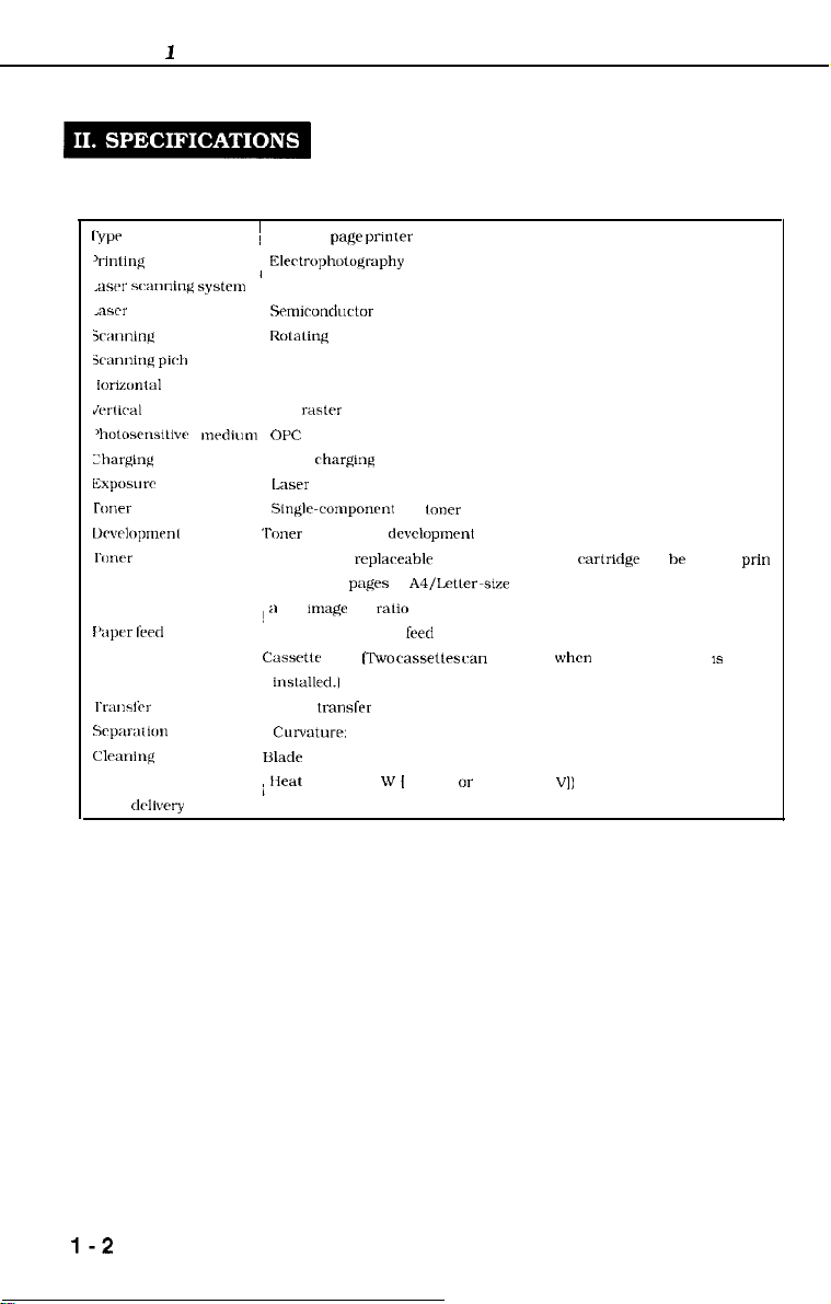
Lype
(parallel or serial) of data from the computer, and automatically l changes the
interface.
(Automatic interface function)
(RS-232C). It
recognizes
I-1
CHAPTER
A. Construction
1
l‘vw
‘I-intinil.
method
,awr
scanning syste”,
<ascr
icar,ninc
system
jczmning
piclr
l<~i?Z”~t~l
JwUral
‘hotosrns~llvr mrdium
L’hargint(
Exposurr
roner
l~rvclop”w”l
I‘1mrr
supply
I’apf,r
fwd
I‘I-~U~Sfil-
Srp~~r-;ltK,”
Clrxring
Fixing
Print delivery
I
~ Desktop
I
OPC
‘lbner
about 6,000
! II
Cassrtk
Blade
; Heat
pa@ printer
Elcctropholoqaphy
Srmicondurtor
Rotaling
600 dots/inch
600 rastc-r lines/inch
Roller
Laser scanning
Singlr-componrnt
projection
Included in
4%
Multi-purpose tray feed
insla1led.l
Roller
Curvature:
roller (500
Fare-down
laser
six-faced prism mirror (Scanning mirror)
rharging
replaceabk
purges
m~agc
dot
ralio
feed [Two
transfer
(small drum radius/paper stiffness)
dry
toner
dcvclopmrnt
EP-E cartridge [The
of
A4/Letler-sxe
with the print density setting in the middle.)
cassetles ran
w
[
115 VI UT 500 w (240
paper. The average print coverage is
be used
r&ridge
when
the paper feeder
VI)
ran be used to
prin
IS
l-2
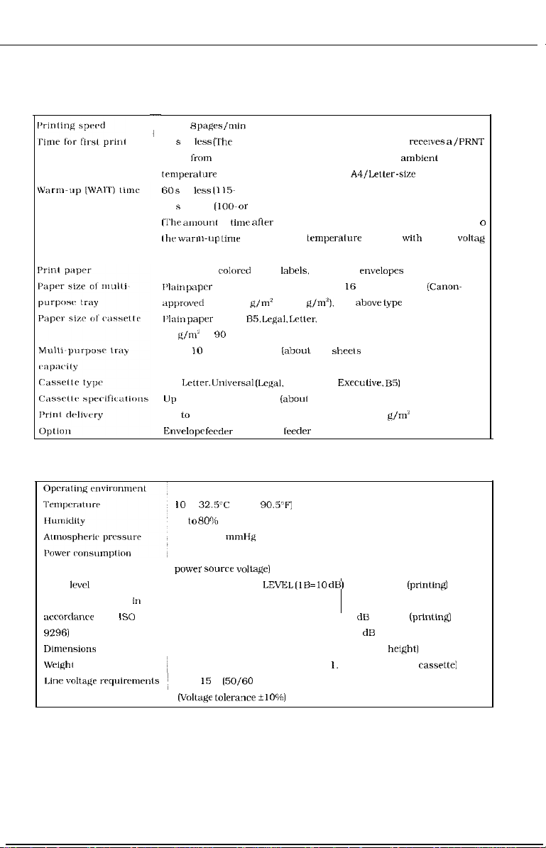
B. Performance
-
About 8
24 s or
pages/min
less (The
I
signal from the video controller when it is ready al an
temprralure
60 s or
less
75 s or less
(The ~~l~ount
the w;un-t~p
input.)
Plain paper,
l’lain
pap”’
approvrd
I’laitr paper
60
g/ml
to 90 g/m’)
Up lo 10 mm stack height
(A4 or Letter)
amount of time from when the printer
of 20°C until the deliver of an
A4/Letler-size
(115- or 2.40-v power source)
(loo- or
220-v power source)
of time
aflrr
the printer is turned ON until the completion
tinw at an ambient
colurcd
paprr. lahels. OHP film,
temperalure
of 20°C with a rated
rnvelopes
from 182 mm X 257 mm to 2 I6 mm X 356 mm (Canon-
paprr, 60
g/m’
to 128 g/m”), and
above type
of A4. B5, Legal. Letler, or Executive (Canon-approved paper
(about
100
shrels
of80 g/m’ paper)
CHAPTER 1
rer~wes a
amhienl
paper.)
of paper
/PRNT
o
voltag
C. Others
Noise levrl (DECLARED
NOISE EMISSIONS in
awordanrr
9296)
with
L)imrnsions
Wright
IS0
A4. Letter.
IJp
Up lo 25 mm stack height (about 250 sheets of 80
Enwlopr
liniwrsal (Lc@l,
to 25 mm stark height
ferdrr
and paper
IO
to
32.5’C
(50 to
90.5-F]
20 to
RO”/u
RH
570 to 760
mmHg
Letter. A4,
(aboul
Execuliw, B5)
250 sheets of 80 g/m’ paper)
leeder
g/m2
paper)
Max. about 660 W (at ambient temperature of 20°C and rated
power source Volta@)
SOUND POWER
LEVEL (lB=lO dB)
6.2 B or less (printin@
4.5 B or less (standby)
SOUND PRESSURE LEVEL 49 dB or less
(printi&
(Bystander positions) 33 dB or less (standby)
424 mm X 4 16 mm X 295 mm (width X depth X heIghtI
17.0 kg (printer). 1.5 kg (cartridge). 1. I kg (A4 or Letter
100-l I5 V
(50/60
Hz], 220-240 V (50 Hz)
(Voltage tolerance ilO%)
cassrttel
1-3
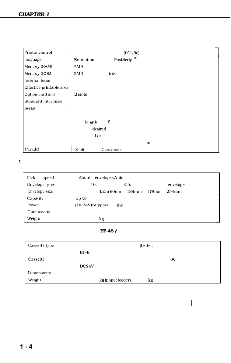
D. Video controller
Standard: Enhanced PCL
Emulahon:
2MB (Expandable to 66 Megabytes in total with optional RAM SIMM)
2MU (Expandable lo 8 Megabytes in total with optional ROM SIMM)
See table 1-I and 1-2.
See figure l-l.
2
KS-232C. asynchronous. 300, 600. 1200. 2400, 4800.9600. 19200. or
38400 baud
Data Icngth: 7 or 8 bits
Parity: 11
Slop bits:
Handshaking: XON-XOFF. ETX-ACK, or DTR
s-bit
1
E. Envelope feeder (Envelope Feeder EF-4)
[‘irk
up
spwd
Envrlolx typ’
~~~~v~~lol~~
size Envelopes from 90mm X 189mm to 178mm X 254mm
i:;lpx ilv
I’0wer supply ~
Dimensions
Wright About 2.6
Up to
Optional PoslScript’M
SlOlS
desired
I or
2
parallel
(Ccntronirs
Aboul
6
env&prs/min
COM-
10.
DL. Monarch. C5, B5 (recommended envelope)
55 mm stark height (about 75 envelopes)
DC24V
(SuppIled by the printer)
306.5 X 293 X 127.9 mm (width X depth X height)
kri
(PCL
5e)
standard) interface
1
F.
Paper feeder (Paper Feeder Unit PF-4s / PF-4L)
EP-E Cassette 500 Universal S
EI’-E
Cassette 500 Universal L (Legal, Letter, A4, Executive)
Casseile
specifications
Power supply
Dimensions
Wciehl
Specifications are subject to change with product improvement.
Up to 50 mm slack height (about 500 sheets of 80 g/m’ paper)
DC24V
(Supplied by the printer)
416 X 470 X 132 mm (width X depth X height) (including legal cover)
About 3.9 ke loauer feedert. about 2 kc (universal cassette1
l-4
[letter,
A4. Executive)
1
CHAPTER 1
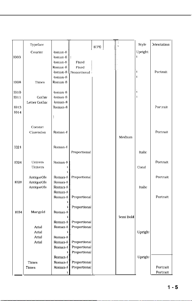
*Scalable Fonts
Font
1000
IO03
1004
1007
IO08
1010
IO11
1012
1013
1014
1015
1016
1017
1018
1019
102
1023
IO24
1025
1028
ID
I
Typefact-
C0llIier
Courier
Courier
Courier
CG Times
CG Times
CG
Time
CG Times
Letter Gothic
Letter GOthic
Letter
CG Omega
CG Omega
CG Omega
CG omega
COi-OlX9
ClX?lldOll
Univrrs
Univrrs
Univers
Univrrs
Univers
Univrrs
Univcrs
Univers
AnliqueOlv
AntiqueOh
AntiqueOh
Garmond
103 1
Garmond
Garmond
1033
1034
1035
1036
1037
1038
1039
1040
104 1
1042
1043
1044
1045
1046
-
Garmond
Marlgold
Aibertus
Aibertus
ArIai
A&l
Aria1
Ariai
Symbol
Times New
Times Bd
Times
Times
New Bdi
Wingdings
Golhir
New It
Symbol
I
ioman-
I
ioman-
I
ioman-
I
ioman-
I
<ornan-
1
ioman-
1
ioman-
I
7oman-8
I
ioman-
I
iOmaw8
I
ioman-
I
ROIIIX-8
I
Roman-8
I
Roman-8
Roman-8
Roman-8
ROKK3n-E
Roman-t
Roman-E
Roman-$
Roman-E
Roman-E
Koman-t
Roman-t
Roman-E
ROITIX-E
ROman-t
Roman-F
Roman-t
ROITXX-t
Roman-F
Roman-E
ROIIXXVE
Roman-E
Roman-E
Roman-E
Roman-E
ROIK%Vt
ROIIlan-E
ROlllan-E
Roman-E
ROman-E
ROllXUl-E
t
ROman-E
Roman-E
set
Table l-l
Spacing
Fixed
Proportional
Proportional
Proportional
Proportional
Fixed
Fixed
Fixed
Proportional
Proportional
Proportional
Proportional
Proportional
Proportional
Proportional
Proportional
Proportional
PrOpOrtiOIlal
Proportional
Proportional
Proportional
Proportional
Proporliondl
Proportional
Proportional
Proportional
ProportIonal
Proportional
ProportIonal
Proportional
Proportional
ProportIonal
ProportIonal
Proportional
Proportional
Proportionai
ProportIonal
Proportlonai
Proportional
PrOpOltIO~.3i
ProportIonal
Proportional
Pitch Point
ICPil Size
,.
‘L
Scalable
I
Stroke
Weight
Medium
Bold
Medium
Bold
Medium
Bold
Mrdium
Bold
Medium
Bold
Medium
Medium
Bold
Medium
Bold
Medium
Bold
Medium
Bold
Medium
Bold
Medium
Bold
Medium
Bold
Medium
Bold
Medium
Medium
Bold
Medium
Bold
Medium
3mlI BoIc
Ex Bold
Medium
Bold
Medium
Bold
Medium
Medium
Bold
Medium
Bold
Medium
I
Style
Lipright
Upright
Italic
Italic
Upright
Upright
Italic
Italic
Upright
Upright
Italic
Upright
Upright
Italic
Italic
Italic
Upright
Upright
Upright
italic
italic
Cond
Cond
Cond It
Cond It
Upright
Upright
Italic
Upright
Upright
Italic
Italic
Upright
Upright
Upright
Upright
UprIght
Italic
Italic
Upright
Upright
UprIght
Italic
Italic
Upright
1rIr‘ntation
Portrait
Portrait
Portrait
Portrait
Porlrait
Portrait
Portrait
Portrait
Portrait
Portrait
Portrait
Portrait
Portrait
Portrait
Portrait
Portrait
Portraii
Portrait
Portrait
Portrait
Portrait
Portrait
Portrait
Portrait
Pot-trait
POrtrait
Portrait
Portrait
Portrait
Portrait
Portrait
Portrait
Portrait
Portrait
Portrait
Portrait
Portrait
Portrait
Portrait
Portrait
Portrait
Portrait
Portrait
Portrait
Portrait
I
1-5
CHAPTER 1
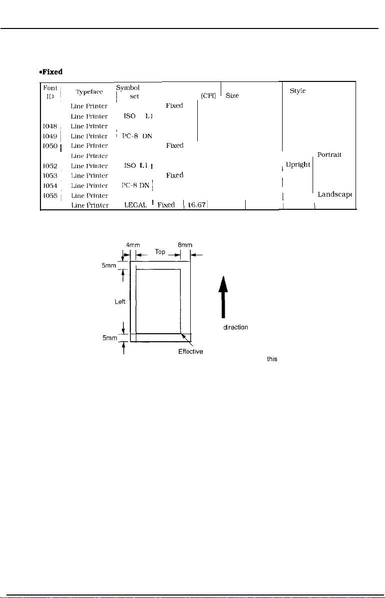
*Fixed
1002
1047
I050 i
1051
1052
1056
Fonts
Linr I’rintcr
Symbol
1
I
Roman-8
:
J’C-R
LEGAL
I
5mm
f
set
IS0
LJ
PC-8
DN
PC-850
IS0
LJ ~
PC-8
PC-R IIN
PC-850
I,EGAL
Table l-2
Sparing
FIxed
Fixed 16.67 8.5
Fixed
Fixed
Fixed
Fixed
Fixed 16.67 8.5
Fixr d
Fixed
I
Fixed
~
Fixed
Bottom
Pitch Point
(CPJJ
sixe
16.67 8.5
16.67: 8.5
16.67 8.5
16.67 8.5
16.67 8.5
16.67’ 8.5
16.67 8.5
16.67, 8.5
(
16.671
8.5
Right
t
Feed-out dIrection
~ff(
sctlve printing area
(Image quality is guaranteed in this area.)
Figure l-l
Stroke
Weight
Medium
Medium
Medium
Medium
Medium
Medium
Medium
Medium
Medium
Medium
Medium
T
Upright Landscape
Upright Portrait
Upright
I
I
I
I
Orientation
Style
Upright Portrait
Upright Portrait
Upright
Upright
Upright Landscape
Upright Landscape
Upright
Upright , Landscape
Portrait
Portrait
Landscape
Landscapc
1-6
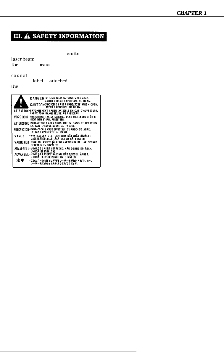
A. Handling the Laser/Scanner Unit
The laser/scanner unit
lasrr
beam.
lhc reflected
possibly damage your eyes. The unit
rannot
following
lhe unit:
Never disassemble the unit;
bram.
be adjusted in the field. The
label
is altached to the cover of
emits
invisible
although invisible. ran
Figure 1-2
1-7
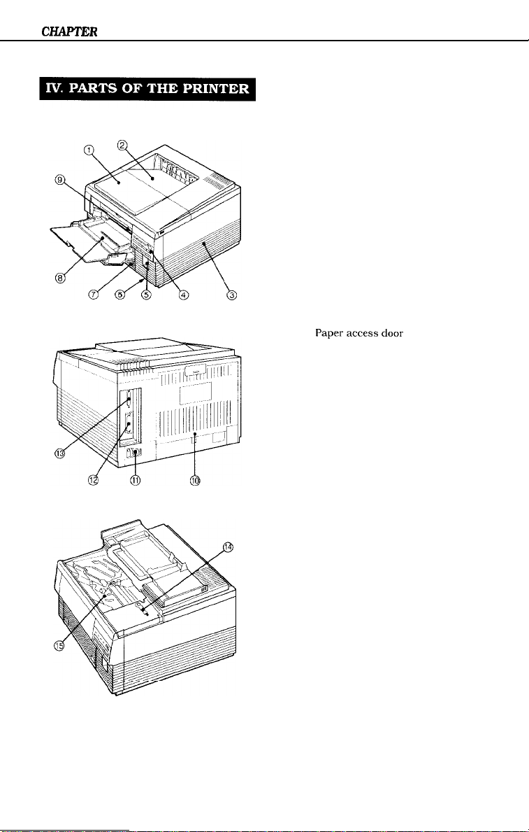
CHAPTER
A. External View
1. Printer
1
Figure l-3
I: Upper cover
2:
Face-down tray
3:
Right rover
4:
Control panel
5: Font card slot
6:
Power switch
7:
Cassette
8:
Multi-purpose tray
9: Test print switch
10:
Delivery cover
11:
Power receptacle
12: Parallel interface connector
13: Serial interface connector
14:
Cleaning brush
15:
Paperaccessdoor
1-8
Figure 1-4
Figure 1-5
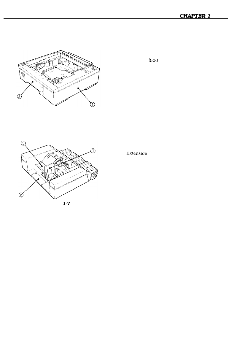
2. Paper feeder
Figure 1-6
3. Envelope feeder
Figure
l-7
1: Paper feeder
2: Cassette
1: Envelope side guide
2:
Exlension
3: Weight
(500
sheets can be placed)
tray
1-9
CHAPTER 1
B. Cross Sectional View
1. Printer
1:
Delivery rollers
2:
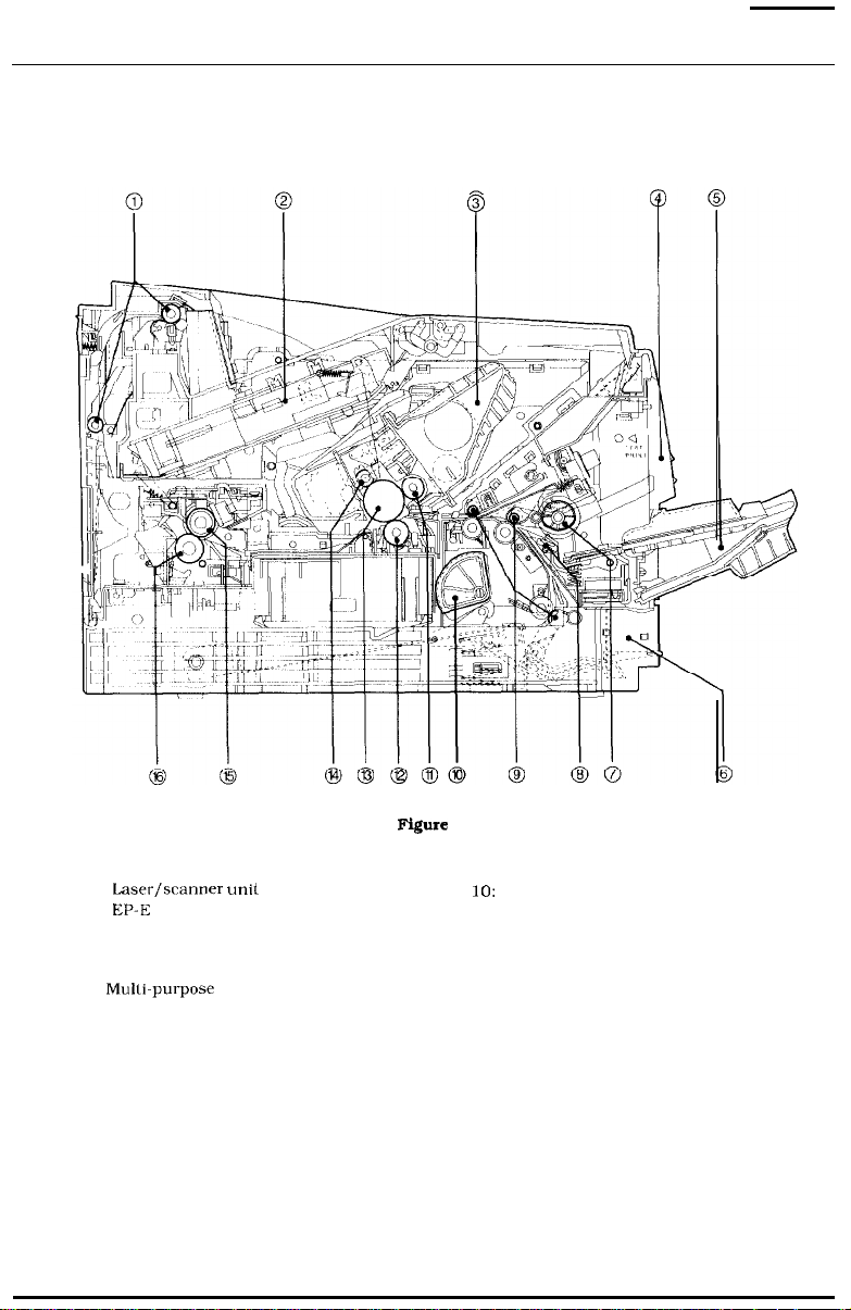
Lasw/scanner unit
3:
EP-E
cartridge
4:
Control
5:
6:
7: Mulli-purpose tray pick-up roller
8:
panel
Multi-purpose tray
Cassette
Separation pad
l-10
Figure
1-s
9:
Oblique rollers
10:
Cassette pick-up roller
11:
Developing cylinder
12: Transfer charging roller
13:
Photosensitive drum
14: Primary charging roller
15: Upper fixing roller
16: Lower fixing roller
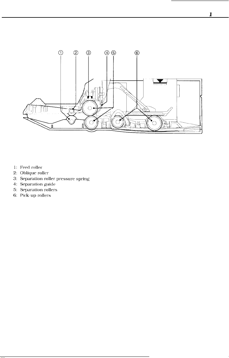
3. Envelope feeder
Figure 1-9
CHAPTER
1
l-11
CHAPTER 1
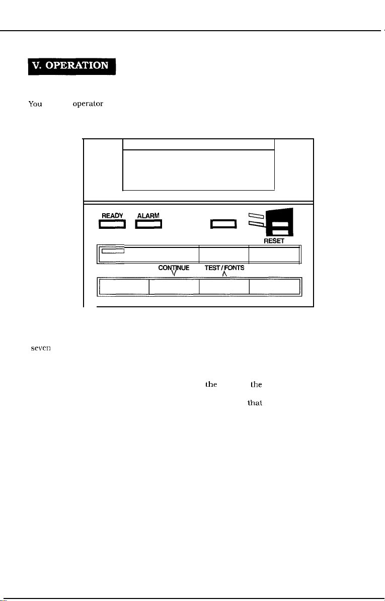
A. The Operator Panel
You
use the operalor panel to perform basic printer operations, make printer configuration
changes your software application cannot control, identify available typefaces, and check the
status of the printer.
READY
on
I-
ALARM
ON LINE
MENU COPQINUE
DATA
1
FORM FEED RESET
TEST/fONTS
a
4zl
ENTER
Figure l-10
The operator panel consists of the message/menu display window, eight indicator lights, and
sewn menu and operation keys.
1. Message/Menu Display Window
The message/menu display window can display as many as 16 characters. It displays menu
items you can select, and messages that describe
lhe
status of
lhe
printer and error conditions.
This chapter describes the menu items you can display in the window. See Chapter 6
‘Troubleshooting, for information about the types of messages that may appear in the window.
1-12
CHAPTER
2. Indicator Lights
The indicator lights provide status information about the printer. The lights have different
meanings depending on whether they are on, off, or flashing.
-_
-
Figure l-11
Indicator
light Mode
READY
ALARM
DATA
ON LINE
Off
Flashing
On
Off
On
Off
On
Off
Description
The printer is ready to print.
An error or attendance message appears in the display.
The printer is receiving data.
An error has occurred and printing is disabled. An error or
attendance message appears in the display.
No error has occurred.
Print data is currently stored in the printer’ s buffer.
No buffered data is in the printer.
The printer is ready to accept and print data from the computer
[on-line
status).
The printer cannot accept print data from the computer (off-line
status). When the printer is off-line.
1
1-13
CHAPTER 1
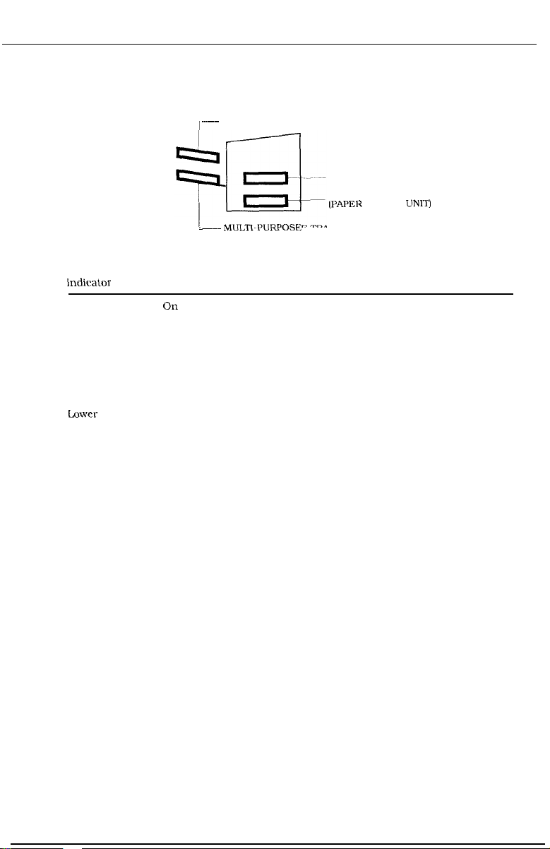
The paper input source indicators are:
~~~~
-~~ MUCKPURPOSE
ENVELOPE FEEDER
TRAY
Figure 1-12
STANDARD CASSETTE
LOWER CASSETTE
(PAPER
FEEDER UNIT)
indicator light
Envelope
Feeder
Multi-purpose
tray
Standard
cassette
Lower
cassette
Mode
On
Flashing
Description
The optional Envelope Feeder is the input source.
The optional Envelope Feeder is selected, but does not
contain envelopes.
On
Flashing
The multi-purpose tray is the input source.
The multi-purpose tray is selected, but does not contain
paper.
On
Flashing
The paper cassette tray is the input source.
The paper cassette tray is selected, but does not contain
paper.
On
The optional Paper Feeder Unit is the input source.
Flashing The optional Paper Feeder Unit is selected, but does not
contain paper.
1-14
CIIAPTER
3. Operation Keys
You
USC
the operation keys to control the basic functions of the printer.
.ON
LINE key
You use the ON LINE key to switch the printer between on-line and off-line. The printer must
be on-line to receive information from your computer. To use any of the other keys on the
operator panel, the printer must be off-line.
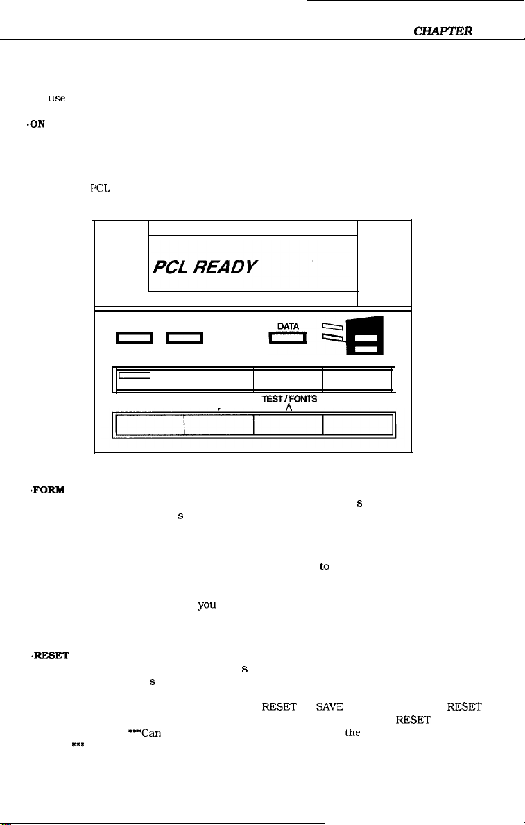
The message PCL READY appears in the display window when the printer is on-line and ready
to receive data.
1
READY
ALARM
III
ON LINE
I
MENU
.FORM
FEED key
You use the FORM FEED key to print the data stored in the printer’ s buffer. For example. if the
last page stored in the printer’ s memory is a full page but your software does not send a
command to print it, you can press ON LINE to set the printer off-line and then press FORM
FEED to print the last page.
Keep in mind that complex pages may take several minutes to process. Make sure the READY
indicator light has stopped flashing before you press FORM FEED lo print the last page.
The printer must be off-line before
Pressing the FORM FEED key does not force a blank sheet through the printer.
*RESET
key
You use the RESET key to clear the printer’ s buffer and remove all temporary typefaces and
macros from the printer’ s memory.
After you change a menu item, you may see the RESET TO SAVE message. If so, press RESKT
to make your menu selections the permanent default settings. The message RESET appears in
the display window.
appear?
***
***Can
CO NUE
V
yoou
press FORM FEED.
we be more specific here? When does lhe RESET TO SAVE message
FORM FEED RESET
TEsT/pNrs
Figure 1-13
ENTER
l-15
CHAPTER
.TEST/FONT key
You use the TEST/FONT key to print the Self Test or the Font List.
When lhe printer is off-line, press the TEST/FONT key once to start the Self Test. Press and
hold the TEST/FONT key to print the Font List. The Self Test and Font List are described later
in this chapter.
*CONTINUE key
You use the CONTINUE key to allow the printer to resume printing after it was placed off-line
by an operational condition. Most operational conditions are identified by a message, such as
PRINT OVERRUN. Before you continue printing, you need to press CONTINUE to clear the
message and
The CONTINUE key sets the printer on-line just like the ON LINE key, but you can also use it
in the following ways:
1
se1
the printer back on-line.
You can press CONTINUE to override the paper or envelope size
media loaded in the multi-purpose tray, lhe optional Envelope Feeder, or a paper cassette.
This means you could use it to print a letter-size page on legal-size paper if legal-size paper
is loaded in the multi-purpose tray
You ran press CONTINUE to override a request to manually feeder paper or an envelope.
When you do this. the printer selects paper from the next available source.
Menu Keys
You use the menu
section briefly describes each key. See the Operator Panel Menus section for information about
accessing and selecting menu items.
4XENU
key
The
MENlJ
The printer must be off-line when you press the MENU key.
You use the and keys to step through all available choices for a particular menu item. For
example. after you access the
display the
You can use the key to display the choices in reverse order. Lf you hold down either arrow key,
the system scrolls rapidly through all choices for the menu option.
.ENTER key
You use the ENTER key to save a selection in the printer’ s permanent memory. An asterisk
appears next to the selection in the menu display window indicating it is the current default
selection. This default selection remains in effect even when you turn off or reset the printer.
If you press ENTER when buffered or temporary data is present, the system only marks the
selections with an asterisk. When you press ON LINE or MENU, the system displays the RESET
TO SAVE message. At this point, you have three choices:
ke.vs
to access the various menus and select the available menu items. This
key cycles through the
LEXTER,
LEGAL, EXEC, A4, COMIO, MONARC. DL,
ME’T
PCI,
PRINT MENU and the PCL CONFIG MENU.
SIZE option from the PCL PRINT MENU, you press to
selecttons
B5.
and C5 choices.
regardless of the
[*I
n
Press RESET to clear the page buffers, remove temporary data, and return all items to their
permanent default setlings.
n
Press ON LINE to place the printer on-line without performing a reset. The selections you
1-16

mad?
in the menu are marked with an asterisk but do not become active until the printer
detects a job boundary or you reset the
W
Press
CONTINUE to set the printer off-line withoul performing a reset.
*** Need to verify all of this ***
CHAPTER 1
prinler.
1-17
CHAFTER
B. Operator Panel Menus
You
n PCL PRINT MENU
n
1
(‘LIT,
access the following menus though the operator panel:
PCL
CONFlG MENU
LIepending
1. Accessing and Selecting Menu Items
Follow these steps to access the menus and make selections:
1.
2. Press MENU once to display the PCL PRINT MENU. Press and hold MENU (for
3.
4.
5. When the selection appears in the display window, press ENTER to save it as the default
6.
2. Confirming Your Menu Selections
There are two ways you ran review the selections you made through the operator panel:
n
n
on the options installed in your
Press ON LINE to
approximately five seconds) to display the PCL CONFIG MENU.
Press MENU until you display the item you want to change.
When
the
the available choices.
setting. An asterisk appears next to your selection in the display window.
Press ON LINE to
You ran scroll through the menu ilems lo check all selections marked with an asterisk.
You
can
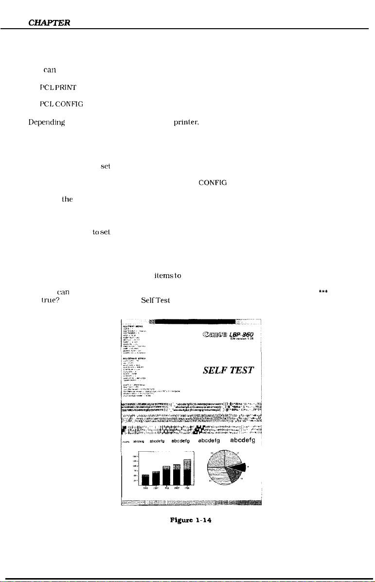
print a Self Test. The printed output lists all settings that are in effect.
Irue?
*** See the Printing the
se1
the printer off-line.
item you want Co change appears in the display window, press or to step through
se1
the printer on-line.
SelfTest
prinler,
other menus may display.
section for more information.
***
Is this
1-18

CHAPTER1
3. Restoring the Default Settings
There are several types of default settings:
n
Factory
default settings are those set for each menu item at the factory. The printer uses
these settings until you change them.
n
Temporary drfaull settings are those set by your application software for the current print
job.
n
Permanent default setlings are those you set through the operator panel. These selections
remain in effect even when you turn off the printer or send a different request through your
application.
You
can
restore the factory default settings by performing a cold reset. To perform a cold reset,
press and hold the ON LINE key while you turn on the printer.
The
printer
comes on-line, the factory default settings are restored.
displays the message COLD RESET followed by WARMING UP. When lhe printer
l-19
CHAPTER
C. PCL PRINT MENU Options
The PCL PKINT MENU contains the most commonly used options. You can override or change
all options in this menu through your software application. The changes you make through the
operator panel become the permanent default settings.
1
I’RlNT
MENU
option
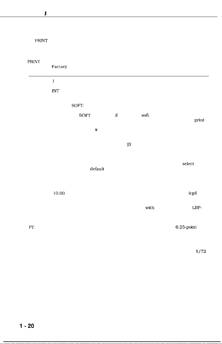
COPIES
FNT SRC
FNT
NUMBEK
PITCH
I-1‘.
SIZE
FX%Ory
default Description
I
IN?‘
0
10.00
Selects the number of copies [from 1 to 99) you want to print.
Selects the font source. You can select:
INT:
CART:
SOFl?:
You see the CART option only if a cartridge is installed, and you see
the
SO@T
If you do not know the font source and font number, you can print a
Font List. The letter you specify here must match the alpha portion
of the Font # on the Font List. For more information about printing
this list. see the Printing the Font List section.
Identifies the Font Number (0 through 999) as listed on the Font
List. Make sure you use the Font # not the Font ID.
If you have installed a font cartridge with a default mark, the
default-marked font overrides the factory default font. The cartridge
default font appears in the PCL PRINT MENU until you selecl a
different
application, you remove the cartridge. or insert a different cartridge
when the default number is 0. The symbol set for the PCL PRINT
MENU is not changed by the marked cartridge.
Selects pitch sizes from 0.44 to 99.99 characters per inch
scroll increments of 0.01. [Hold down the arrow key to increment
rapidly.) You can select a pitch if the font indicated by FNT SRC and
FNT NUMBER is a scalable typeface with fixed spacing. The
860 adjusts the height (point size) of the characters according to the
pitch you select.
12.00
Selects the point size from 4.00 to 999.75 points in 0.25.point
increments. The scroll increment is 0.25 or 1.00 (if you hold down
the arrow key). You can select the point size if the font indicated by
FNT SRC and FNT NUMBER is a scalable font with proportional
spacing.
Point size is a measure of the vertical height of a character in l/72
of an inch. The LBP-860 adjusts the character’s horizontal spacing
according to the point size you select.
Internal fonts
Cartridges
Permanent soft font
option only if permanent salt fonts are downloaded.
deCault
through the operator panel or your software
(cpi)
in
LBP-
l-20
PRINT
MENU
option
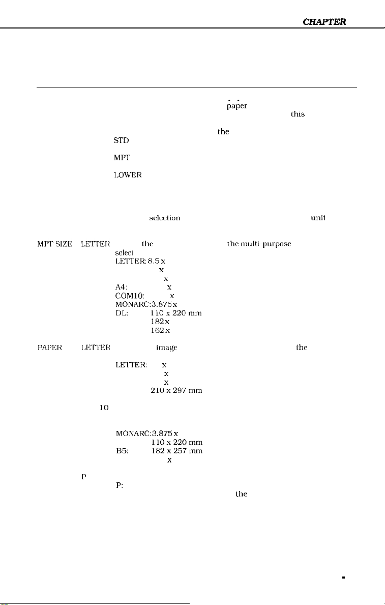
TRAY ALL
Factory
default Description
Selects how the printer will load paper. You can select:
ALL Loads paper from any
STD
MPT
1,OWER
ENV
Selects
selerl :
LEKITEK: 8.5 x
LEGAL 8.5 x 14 inches
EXEC:
A4: 2 10 x 297 mm
COMlO: 4.125 x 9.5 inches
MONARC:3.875 x 9.5 inches
r)k
H5: 182 x
C5:
Selects the
a software command overrides it. You ran select:
LMTER:
LEGAL:
EXEC:
A4:
loads from the standard cassette first: if
empty, it loads from the lower cassette (if the Paper Feeder
Unit is installed) or lhe multi-purpose tray.
Loads from the standard paper cassette only: if this
cassette is empty, you see an error message.
Loads from the multi-purpose tray only; if this tray is
empty, you see an error message.
Loads from the optional Paper Feeder Unit only; if this
cassette is empty, you see an error message. You see this
selection only if the optional Paper Feeder Unit is installed.
Loads from the optional Envelope Feeder unit only; if this
feeder is empty, you see an error message. You see this
sclcrtion only if the optional Envelope Feeder
installed.
the
paper size loaded in the
11 inrhrs
7.5 x 10.5 inches
llOx220mm
257 mm
162
x 219 mm
image
size al which the printer formats
8.5 x 11 inches
8.5 x 14 inches
7.5 x 10.5 inches
21Ox297mm
l&&r
input source. The printer
multi~purpose
tray. You can
Lhis
CZ-LAPTER
cassette is
unil
is
the
page unless
1
ENVELOPE COM
ORIENTATI
ON
E’
10
Selects the image sue at which the printer formats the envelope
unless a software command overrides it. You see this menu item
only if the optional Envelope Feeder is installed. You can select:
MONARCz3.875 x
DL:
B5:
c5:
Selects the direction of print on the page.
P:
L:
You can print in reverse portrait or reverse landscape orientations
by making selections through your software application or using
printer commands. The LBP-860 has a font rotation feature which
makes all fonts available in all orientations.
9.5 inches
llOx220mm
l82x257mm
162 x 219 mm
Portrait prints along the width of the page
Landscape prints along lhe length of the page
1 - 21
CHAPTER 1
I’RIN’I
MENU
option
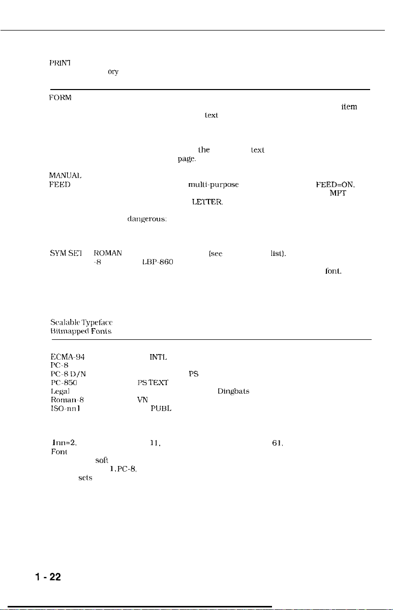
Fart
“l-y
default Description
FORM
MANIJAI,
FIXD
SYM SF1
Scalable ‘lypefkcc and
t%iLnlapprd Fonts
Roman-8
ECMA-94 Latin 1
X-8
PC-K D/N
PC850
Legal
Rornarl-8
ISO-nn
German
Spanish
60
LINES
OFF
I
Selects the number of lines to print on each page (5 through 128) as
well as the amount of space between lines. The FORM menu
places the first line of lext at the top margin, the last line of text at
the bottom margin. and spaces the remaining lines equally between
them. Make sure the text length setting in your software application
matches the value you use for this item. If it is set lo a greater value
in your application, lhe first line of texl may begin successively
lower on each
Turns the manual feed function ON or OFF. Manual feed is available
only through the mulli-purpose tray. When MANUAL FEED=ON. the
printer goes off-line when a print job is sent and displays MPT TRAY
followed by LOAD LELTER. Press the RESET key to manually feed
the media in the multi-purpose tray. *** Pressing the RESET key is
da~lgerous:
the buffer! *** To override a manual feed request, press the
CONTINUE key.
Selects the symbol set
The IBl’-860 provides 40 symbol sets you can choose. A symbol set
is a unique grouping of all the available characters in a
listing shows the internal symbol sets you can select from the
operator panel.
Scalable Typefaces Only
VN MATH WINDOWS
VN INTL DESKTOP
VN US
I’S MATH
I’S TFXT
MATH-8
VN
MS PUBL
page.
if the user presses the key loo long, it erases the data in
[see
VN DING
I
MATH WINDOWS
I’S DING
DING 1
DING 2
Dingbats
the following
lisl).
fonl.
item
This
1
nn=2.
4. 6 (US ASCII). 10.
Font
List printout shows all symbol sets for installed cartridges and permanent
downloaded soli fonts. Internal bitmapped font symbol sets are only shown in Roman-8,
ECMA-94, Latin I,
symbol srts appear on the PCL Font List printout only if selected as the default symbol set
from the operator panel.
PC-B,
1 I.
14, 15, 16. 17, 21, 25, 57, 60,
PC-8 D/N, PC-850, and Legal. The remaining selectable internal
61,
69, 84, or 85. The PCL
I-22
D. PCL CONFIG MENU Options
The PCL
CONFIG
override or change options in this menu through your software applicalion.
MENU controls certain
conflguration
settings for your LBP-860. You cannot
CHAPTER 1
The I/O oplion allows you to set up the communication parameters for
you
arc
using it).
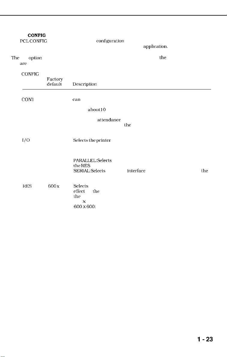
CONFIG
MENU Farto1y
option
AUTO ON
CON-1
I/O
RES
del%ult
AUTO
tiO0 x
Desrriplion
Determines how the printer reacts Lo data and printer errors. You
can
select:
Any non-critical error message appears on the display for
ON:
aboul 10 seconds: then the PCL READY message appears
and printing resumes.
OFF:
Any atlrndancc or error message remains in the display
until you correct lhe problem, tell the printer to continue.
or both.
Selecls
thr-
AUTO: Allows the printer to determine the interface port. which
PAKALLEL:Selects the parallel interface only. The printer skips to
the
SEKIAL:Selects the serial inlerfare only. The printer displays the
communications options described in the next section.
Sclwls
600
eff&l
the
300 x 300:
600 x 600:
prinlcr interface. You can select:
can lx either parallel or serial. The printer displays the
communications options described in the next section.
KES menu option.
300 or 600 dpi. When you change resolution, it lakes
for ihe next print job or when you reset the printer through
operator panel. You can select:
for graphics and fonts designed for 300 dpi.
for graphics and fonts designed for 600 dpi; use
when document contains a mix of 300 and 600 dpi
bitmaps.
the
serial interface (if
l-23
CHAPTER
1
CONFIG
MENU
option deSa&
PG I’ROT
FXtory
OFF
Description
Reserves additional memory for the page imaging process. This
allows the printer to create the complete page image in memory
before paper starts through the printer, which ensures the entire
page is printed. The value you set for page protection does not
lake effect until you reset the printer or it encounters a job
boundary. *** Is this true?
The complexity of a page may exceed the printer’s ability to
create
the image and keep pace with the printing process. If a
page is too complex. the page may print in parts. or only part of
the page may print. II data loss occurs, the PRINT OVERRUN
nwssage
appears in the display. If you often receive this message,
you may
page
The memory required for page protection is dependent on the
four times more memory than a page at 300 dpi. If you use page
you select. The figures shown here include 2MB of internal
wed
protection.
protcrtion. set it for
Makr sure you have sufficient memory installed for the option
memory. You can select:
OFF:
LTR:
124:
LGL:
t’rint
You ran experiment with different settings to find the best setting
lor
your print job. To make print darker, use a higher
make print tighter, use a lower setting. The selections are from 0
Io
15.
to install additional memory and set a value for
requires minimum inslalled memory of 2MH for 300 and
600
dpi.
requires 2MB for 300 dpi:
requires
requires 3MB for 300 dpi: 6MB for 600 dpi.
density is a measure of the darkness of print on the page.
***
A page at 600 dots per inch
the
paper size you expect to use most often.
2MB
for 300 dpi:
6MB
for 600 dpi.
6MB
for 600 dpi.
(dpi)
requires
selting:
to
NOTE: When you set lhe density to a higher level.
LANG
dhnmunications
Thhc
I/O option allows you lo set up the communication parameters for the serial interface (if
you arc {Ising it).
II you set I/O to AUTO or SERIAL. you see the
t
IANDSMK
ENGLISH
Menu
9600
ROBUST Selects the handshake method for controlling data transfer
The
LBP-860
supports the English language.
liillowing
menu options:
Determines the rate at which information is transferred between
the computer and printer. You can selecl300, 600. 1200, 2400.
4800, 9600. 19200. 38400, or 57600.
between the computer and printer. For RS-232C operation, you
can select ROBUST, XON, or N/W.
l-24
 Loading...