

LBP6670dn/6680x Series
Product Description
Technology
Disassembly/Assembly
Maintenance and Inspection
Trouble Shooting
Appendex
Service Manual
54321
F-0-1

0
0-2
Application
This manual has been issued by Canon Inc. for qualied persons to learn technical theory,
installation, maintenance, and repair
of products. This manual covers all localities where the products are sold. For this reason,
there may be information in this
manual that does not apply to your locality.
Corrections
This manual may contain technical inaccuracies or typographical errors due to improvements
or changes in products. When
changes occur in applicable products or in the contents of this manual, Canon will release
technical information as the need
arises. In the event of major changes in the contents of this manual over a long or short
period, Canon will issue a new edition
of this manual.
The following paragraph does not apply to any countries where such provisions are
inconsistent with local law.
Trademarks
The product names and company names used in this manual are the registered trademarks
of the individual companies.
Copyright
This manual is copyrighted with all rights reserved. Under the copyright laws, this manual
may not be copied, reproduced or
translated into another language, in whole or in part, without the written consent of Canon Inc.
0
(C) CANON INC. 2012
Caution
Use of this manual should be strictly supervised to avoid disclosure of condential
information.
0-2

0
0-3
Explanation of Symbols
The following symbols are used throughout this Service Manual.
Symbols Explanation Symbols Explanation
Used to show permission. Remove the screw.
Used to show prohibition. Tighten the screw.
Check. Remove the claw.
Check visually. Insert the claw.
Check the noise. Use the bundled part.
The following rules apply throughout this Service Manual:
1. Each chapter contains sections explaining the purpose of specic functions and the
relationship between electrical and mechanical systems with reference to the timing of
operation.
In the diagrams, represents the path of mechanical drive; where a signal name
accompanies the symbol, the arrow indicates the direction of the electric signal.
The expression "turn on the power" means ipping on the power switch, closing the front
door, and closing the delivery unit door, which results in supplying the machine with power.
2. In the digital circuits, '1' is used to indicate that the voltage level of a given signal is "High",
while '0' is used to indicate "Low". (The voltage value, however, differs from circuit to
circuit.) In addition, the asterisk (*) as in "DRMD*" indicates that the DRMD signal goes on
when '0'.
In practically all cases, the internal mechanisms of a microprocessor cannot be checked
in the eld. Therefore, the operations of the microprocessors used in the machines are not
discussed: they are explained in terms of from sensors to the input of the DC controller
PCB and from the output of the DC controller PCB to the loads.
The descriptions in this Service Manual are subject to change without notice for product
improvement or other purposes, and major changes will be communicated in the form of
Service Information bulletins.
All service persons are expected to have a good understanding of the contents of this Service
Manual and all relevant Service Information bulletins and be able to identify and isolate faults
in the machine.
0
Disconnect the connector. Push the part.
Connect the connector. Plug the power cable.
Remove the cable/wire
from the cable guide or wire
saddle.
Set the cable/wire to the
cable guide or wire saddle.
Turn on the power.
T-0-1
0-3

Contents
Safety Precautions
Safety Information ------------------------------------------------------------0-6
Laser Safety ------------------------------------------------------------------------- 0-6
CCDRH Regulation ---------------------------------------------------------------- 0-6
Toner Safety ------------------------------------------------------------------------- 0-6
About Toner ---------------------------------------------------------------------------------- 0-6
How to Handle Adhered Toner ---------------------------------------------------------- 0-6
Ozone Safety ----------------------------------------------------------------------- 0-6
How to Handle the Laser Scanner Unit -------------------------------------- 0-7
Points to Note when Replacing/Discarding a Lithium Battery ---------- 0-7
Points to Note when Performing Disassembly/Assembly---------------- 0-7
Product Description
Product Lineups ---------------------------------------------------------------1-2
Main unit ----------------------------------------------------------------------------- 1-2
Options ------------------------------------------------------------------------------- 1-2
Features -------------------------------------------------------------------------1-2
Specication --------------------------------------------------------------------1-3
Product Specications ------------------------------------------------------------ 1-3
Printing Speed --------------------------------------------------------------------- 1-3
List of Parts ---------------------------------------------------------------------1-4
External View ----------------------------------------------------------------------- 1-4
Cross Sectional View ------------------------------------------------------------- 1-4
Operation ------------------------------------------------------------------------1-5
Control panel ------------------------------------------------------------------------ 1-5
Technology
Basic Operation ---------------------------------------------------------------2-2
Function Structure ----------------------------------------------------------------- 2-2
Sequence of Operation ------------------------------------------------------2-2
Outline -------------------------------------------------------------------------------- 2-2
Laser Exposure System -----------------------------------------------------2-3
Outline -------------------------------------------------------------------------------- 2-3
Optical Unit Failure Detection --------------------------------------------------- 2-3
Image Formation System ---------------------------------------------------2-4
Outline -------------------------------------------------------------------------------- 2-4
Image Formation Process ------------------------------------------------------- 2-4
Outline ----------------------------------------------------------------------------------------- 2-4
Latent image formation block ------------------------------------------------------------ 2-5
Developing block---------------------------------------------------------------------------- 2-5
Transfer block ------------------------------------------------------------------------------- 2-6
Fixing block ----------------------------------------------------------------------------------- 2-6
Drum cleaning block ----------------------------------------------------------------------- 2-6
High-voltage Power Supply ----------------------------------------------------- 2-7
Outline ----------------------------------------------------------------------------------------- 2-7
Fixing System ------------------------------------------------------------------2-8
Outline -------------------------------------------------------------------------------- 2-8
Fixing control circuit --------------------------------------------------------------- 2-9
Small Size Paper Printing Speed Control (Throughput Reduction Control) - 2-9
Fixing temperature control---------------------------------------------------------------2-10
Protective function -------------------------------------------------------------------------2-10
Failure detection ---------------------------------------------------------------------------2-11
Pickup Feeding System --------------------------------------------------- 2-12
Outline -------------------------------------------------------------------------------2-12
Jam Detection ---------------------------------------------------------------------2-13
Outline ----------------------------------------------------------------------------------------2-13
Pickup Delay Jam -------------------------------------------------------------------------2-13
Pickup Stationary Jam--------------------------------------------------------------------2-13
Delivery Delay Jam ------------------------------------------------------------------------2-13
Fixing Paper Wrap Jam -----------------------------------------------------------------2-13
Delivery Stationary Jam ------------------------------------------------------------------2-13
Reverse Delay Jam -----------------------------------------------------------------------2-13
Reverse Stationary Jam -----------------------------------------------------------------2-14
Internal Residual Jam --------------------------------------------------------------------2-14
Door Open Jam ----------------------------------------------------------------------------2-14
Controller System ----------------------------------------------------------- 2-15
Outline -------------------------------------------------------------------------------2-15
DC Controller ----------------------------------------------------------------------2-15

Outline ----------------------------------------------------------------------------------------2-15
Motor control --------------------------------------------------------------------------------2-16
Fan control ----------------------------------------------------------------------------------2-17
Failure Detection ---------------------------------------------------------------------------2-17
Low-voltage Power Supply ----------------------------------------------------- 2-17
Outline ----------------------------------------------------------------------------------------2-17
Protective function -------------------------------------------------------------------------2-18
Safety -----------------------------------------------------------------------------------------2-18
Low-voltage power supply unit failure detection -----------------------------------2-18
Energy Saving Function ---------------------------------------------------------2-18
MEAP -------------------------------------------------------------------------- 2-19
Introduction -------------------------------------------------------------------------2-19
References by purpose ------------------------------------------------------------------2-19
About MEAP -----------------------------------------------------------------------2-19
Overview -------------------------------------------------------------------------------------2-19
About SMS -------------------------------------------------------------------------2-20
Overview -------------------------------------------------------------------------------------2-20
About the MEAP Application Management Screen -------------------------------2-20
About the MEAP Application Installation Screen ----------------------------------2-20
About System Management ------------------------------------------------------------2-21
Preparation for Using SMS -----------------------------------------------------2-21
Preparation of PC for Accessing SMS -----------------------------------------------2-21
Device Settings -----------------------------------------------------------------------------2-22
How to Check the Serial Number ------------------------------------------------------2-27
Login to SMS -----------------------------------------------------------------------2-28
Procedure to Log in -----------------------------------------------------------------------2-28
Installing an MEAP Application ------------------------------------------------2-31
Outline ----------------------------------------------------------------------------------------2-31
Procedure to install applications -------------------------------------------------------2-31
Resource Information ------------------------------------------------------------2-33
About MEAP Application Management Page ---------------------------------------2-33
MEAP Specications -------------------------------------------------------------2-34
What is MEAP Specications (MEAP Spec Version)? ---------------------------2-34
MEAP Application Management ----------------------------------------------2-36
Outline ----------------------------------------------------------------------------------------2-36
Starting, Stopping, or Uninstalling the MEAP Application -----------------------2-36
Managing the License File --------------------------------------------------------------2-38
Other License File Management Functions -----------------------------------------2-42
Enhanced System Application Management-------------------------------2-45
Outline ----------------------------------------------------------------------------------------2-45
About Login Service-----------------------------------------------------------------------2-45
Default Authentication overview--------------------------------------------------------2-45
Other Log in service-----------------------------------------------------------------------2-45
Procedure Changing Login Services -------------------------------------------------2-45
Procedure Installing Login Services --------------------------------------------------2-46
Procedure Uninstalling Login Services -----------------------------------------------2-47
System Application Management ---------------------------------------------2-47
Procedure to manage System Application ------------------------------------------2-47
System Information ---------------------------------------------------------------2-48
Outline ----------------------------------------------------------------------------------------2-48
Checking the System Information -----------------------------------------------------2-48
Display of System Information Details------------------------------------------------2-48
Printing the System Information of a MEAP Application -------------------------2-49
Content of MEAP system information ------------------------------------------------2-49
MEAP Application Information -------------------------------------------------2-50
Outline ----------------------------------------------------------------------------------------2-50
Procedure to Check MEAP Application Information ------------------------------2-50
Check License ---------------------------------------------------------------------2-51
Outline ----------------------------------------------------------------------------------------2-51
Procedure to Check the License File -------------------------------------------------2-51
Changing SMS Login Password ----------------------------------------------2-51
Outline ----------------------------------------------------------------------------------------2-51
Procedure to Change the SMS Login Password ----------------------------------2-51
MEAP Application Setting Information Management and Log
Management -----------------------------------------------------------------------2-52
Outline ----------------------------------------------------------------------------------------2-52
Advantages Obtained When Using the Services ----------------------------------2-52
MEAP Application Setting Information Management -----------------------------2-53
MEAP Application Log Management -------------------------------------------------2-53
Maintenance -----------------------------------------------------------------------2-54
When Replacing the PCB ---------------------------------------------------------------2-54
Actions to be taken when E616 is displayed. ---------------------------------------2-55
MEAP Safe Mode --------------------------------------------------------------------------2-56
Using USB Devices -----------------------------------------------------------------------2-57
Reference material ---------------------------------------------------------------2-58
Glossary --------------------------------------------------------------------------------------2-58

Embedded RDS ------------------------------------------------------------- 2-61
Product Overview -----------------------------------------------------------------2-61
Overview -------------------------------------------------------------------------------------2-61
Features and benets --------------------------------------------------------------------2-61
Service cautions -------------------------------------------------------------------2-62
E-RDS Setup -----------------------------------------------------------------------2-62
Conrmation and preparation in advance -------------------------------------------2-62
E-RDS setting items (service mode) --------------------------------------------------2-63
Steps to E-RDS settings -----------------------------------------------------------------2-63
Initializing E-RDS settings ---------------------------------------------------------------2-65
FAQ -----------------------------------------------------------------------------------2-66
Troubleshooting -------------------------------------------------------------------2-67
Error code and strings -----------------------------------------------------------2-69
Disassembly/Assembly
Preface --------------------------------------------------------------------------3-2
List Of Parts --------------------------------------------------------------------3-2
External View ----------------------------------------------------------------------- 3-2
List of Main Unit -------------------------------------------------------------------- 3-3
Motor ---------------------------------------------------------------------------------- 3-4
Solenoid ------------------------------------------------------------------------------ 3-5
Heater / Thermo Switch / Thermistor / Switch ------------------------------ 3-5
Sensor -------------------------------------------------------------------------------- 3-6
PCB ----------------------------------------------------------------------------------- 3-6
Connector Layout Drawing -------------------------------------------------3-7
Connector List ---------------------------------------------------------------------- 3-7
Main Controller PCB ----------------------------------------------------------------------- 3-7
Engin Controller PCB ---------------------------------------------------------------------- 3-7
Internal ---------------------------------------------------------------------------------------- 3-7
External Cover, Internal Cover ---------------------------------------------3-9
Removing the Left Cover -------------------------------------------------------- 3-9
Removing the Right Cover ------------------------------------------------------ 3-9
Removing the Rear Cover Unit / Duplex Feed Unit ---------------------- 3-10
Removing the Upper Cover Unit ---------------------------------------------- 3-11
Removing the Cartridge Cover Unit ------------------------------------------ 3-11
Controller System ----------------------------------------------------------- 3-12
Removing the Main Controller Board ---------------------------------------- 3-12
Actions before Replacement ------------------------------------------------------------3-12
Removing the Main Controller Board -------------------------------------------------3-12
Actions before Replacement (LBP6670 only) --------------------------------------3-13
Remove the Sleep Interface PCB --------------------------------------------3-14
Remove the Duplex Reverse Sensor Unit ----------------------------------3-14
Remove the All-Night Power Supply PCB ----------------------------------3-15
Remove the Power Supply PCB ---------------------------------------------- 3-15
Removing the Engine Controller Board -------------------------------------3-16
Removing the Control Panel Unit ---------------------------------------------3-18
Removing the Main Motor ------------------------------------------------------3-19
Removing the Main Fan ---------------------------------------------------------3-19
Removing the Main Drive Unit -------------------------------------------------3-20
Removing the Duplex Drive Unit ----------------------------------------------3-21
Removing the Cassette Pickup Solenoid ----------------------------------- 3-22
Removing the Multi-purpose Solenoid ---------------------------------------3-22
Removing the Duplex Reversal Solenoid -----------------------------------3-23
Laser Exposure System --------------------------------------------------- 3-24
Removing the Laser Scanner Unit --------------------------------------------3-24
Image Forming System ---------------------------------------------------- 3-25
Removing the Transfer Roller --------------------------------------------------3-25
Removing the Registration Unit ----------------------------------------------- 3-25
Fixing System ---------------------------------------------------------------- 3-27
Removing the Fixing Unit ------------------------------------------------------- 3-27
Paper Pickup/Transport/Output System ------------------------------- 3-29
Removing the Cassette Pickup Roller ---------------------------------------3-29
Removing the Cassette Separation Pad ------------------------------------3-30
Removing the Multi-purpose Pickup Roller ---------------------------------3-30
Removing the Multi-purpose Separation Pad------------------------------3-31
Maintenance and Inspection
Periodically Replaced Parts ------------------------------------------------4-2
Periodically Replaced Parts ----------------------------------------------------- 4-2
Consumable Parts ------------------------------------------------------------4-2
Durables Replaced by the Service Person ---------------------------------- 4-2
Periodical Service -------------------------------------------------------------4-2

Periodical Service ------------------------------------------------------------------ 4-2
Cleaning -------------------------------------------------------------------------4-2
Cleaning at Service Visit --------------------------------------------------------- 4-2
Trouble Shooting
Trouble Shooting --------------------------------------------------------------5-2
Test Pages --------------------------------------------------------------------------- 5-2
Engine-test page ---------------------------------------------------------------------------- 5-2
Controller-Test page ----------------------------------------------------------------------- 5-2
Device Log List --------------------------------------------------------------------- 5-3
Adjustment of Fixing System ---------------------------------------------------- 5-3
Nip-width specications ------------------------------------------------------------------- 5-3
Error Codes ---------------------------------------------------------------------5-4
Error Code Details ----------------------------------------------------------------- 5-4
Jam Codes -------------------------------------------------------------------------- 5-7
Service Mode ------------------------------------------------------------------5-8
ADJUST GR. --------------------------------------------------------------------------------- 5-8
OPTION GR. --------------------------------------------------------------------------------- 5-8
FUNCTION GR. ----------------------------------------------------------------------------- 5-8
LOG GR. -------------------------------------------------------------------------------------- 5-9
PANEL GR ------------------------------------------------------------------------------------ 5-9
F/W UPDATE GR. -------------------------------------------------------------------------- 5-9
NETWORK GR. ----------------------------------------------------------------------------- 5-9
SP.ADMIN.MODE ------------------------------------------------------------------------- 5-11
Version Upgrade ------------------------------------------------------------ 5-12
Overview ----------------------------------------------------------------------------5-12
Overview of Version Upgrade ----------------------------------------------------------5-12
Checking the Version ---------------------------------------------------------------------5-12
Version Upgrade Using UST ---------------------------------------------------5-13
Preparation ----------------------------------------------------------------------------------5-13
Downloading the Firmware --------------------------------------------------------------5-14
Updater ------------------------------------------------------------------------ 5-17
Overview ----------------------------------------------------------------------------5-17
Outline ----------------------------------------------------------------------------------------5-17
System Conguration ---------------------------------------------------------------------5-18
List of Functions ----------------------------------------------------------------------------5-18
Distribution Flow ---------------------------------------------------------------------------5-19
Limitations and Cautions-----------------------------------------------------------------5-20
Preparation ----------------------------------------------------------------------------------5-21
System Management Operations------------------------------------------------------5-27
a. UGW-linked Download and Update (Full-remote Update) -------------------5-30
b. UGW-linked Download (Remote Distribution Update) ------------------------5-30
Deleting the Scheduled Firmware Delivery -----------------------------------------5-31
Updating the Downloaded Firmware (Application of Firmware) ---------------5-31
Deleting the Downloaded Firmware --------------------------------------------------5-32
Maintenance --------------------------------------------------------------------------------5-33
FAQ -------------------------------------------------------------------------------------------5-34
Error Messages ----------------------------------------------------------------------------5-37
Error Codes ---------------------------------------------------------------------------------5-43
Debug log --------------------------------------------------------------------- 5-48
Sublog -------------------------------------------------------------------------------5-48
Function Overview ------------------------------------------------------------------------5-48
How the log is written ------------------------------------------------------------5-48
Collecting Sublog -----------------------------------------------------------------5-49
Flow of collecting Sublog ----------------------------------------------------------------5-49
Installing the Sublog Board--------------------------------------------------------------5-49
Generating the log -------------------------------------------------------------------------5-49
Collecting log -------------------------------------------------------------------------------5-50
Backup/Restoration by Expansion ROM for servicing and Sublog
Board --------------------------------------------------------------------------- 5-53
Function Overview ----------------------------------------------------------------5-53
What to Prepare ----------------------------------------------------------------------------5-53
Prerequisites --------------------------------------------------------------------------------5-53
Target Data for Backup -------------------------------------------------------------------5-53
Backup and Restoration (Export and Import) ------------------------------ 5-54
Flow of Export and Import ---------------------------------------------------------------5-54
Installing the Expansion ROM for servicing and Sublog Board ----------------5-54
Backup Procedure (Export) -------------------------------------------------------------5-55
Restoration Procedure (Import) --------------------------------------------------------5-55
Others -------------------------------------------------------------------------------- 5-56
Deletion (Erase) ----------------------------------------------------------------------------5-56
List of Error Messages -------------------------------------------------------------------5-57
Appendex
Service Tools --------------------------------------------------------------------- II

Special Tools --------------------------------------------------------------------------- II
Solvents and Oil List ----------------------------------------------------------------- II
General Timing Chart ----------------------------------------------------------III
General Timing Chart ------------------------------------------------------------------------ III
General Circuit Diagram ------------------------------------------------------ IV
General Circuit Diagram ----------------------------------------------------------- IV
Backup Data ---------------------------------------------------------------------- V

SafetyPrecautions
■LaserSafety
■CCDRHRegulation
■TonerSafety
■OzoneSafety
■HowtoHandletheLaserScannerUnit
■Points to Note when Replacing/Discarding a Lithium
Battery
■PointstoNotewhenPerformingDisassembly/Assembly

0
Safety Precautions > Safety Information > Ozone Safety
0-10
Safety Information
Laser Safety
Laser beam radiation sometimes causes a danger to human body. To prevent such a danger,
the optical laser system used in this machine is hermetically closed by the protection housing
and external cover so that a laser beam does not leak to outside. Therefore, a laser beam
does not leak out of this machine as long as a user operates the machine in an ordinary
manner.
CCDRH Regulation
CDRH (Center for Devices and Radiological Health), which belongs to Food and Drug
Administration in USA, put a regulation concerning laser products on August 2, 1976. This
regulation is applied to laser products manufactured on and after August 1, 1976, and sales
activities are prohibited in USA without receiving permission under the regulation.
The following gure shows the label indicating that permission has been received under the
CDRH regulation, and it is obliged to attach it on all products sold in USA.
Toner Safety
■About Toner
Toner is a nontoxic substance which consists of plastic, iron, and a small amount of pigment.
CAUTION:
Be sure not to throw toner into the re. Doing so may cause an explosion.
■How to Handle Adhered Toner
When toner adhered to skin or clothes, completely remove it with dried tissue and wash with
water.
If hot water is used, toner cannot be removed because it becomes gel and penetrates into
clothes permanently.
Do not make toner come into contact with vinyl because it easily reacts with a vinyl materia
Ozone Safety
An innitesimal amount of ozone gas (O3) is generated during corona discharge from the
charging roller
used in this printer. The ozone gas is emitted only during the printer operation.
The printer meets ozone emission reference value set by Underwriters Laboratory (UL) at the
time ofshipping from the manufacture.
CAUTION:
A part of the description may be different depending on the type of product model.
Safety Precautions > Safety Information > Ozone Safety
0
F-0-2
0-10
0
Safety Precautions > Safety Information > Points to Note when Performing Disassembly/Assembly
0-11
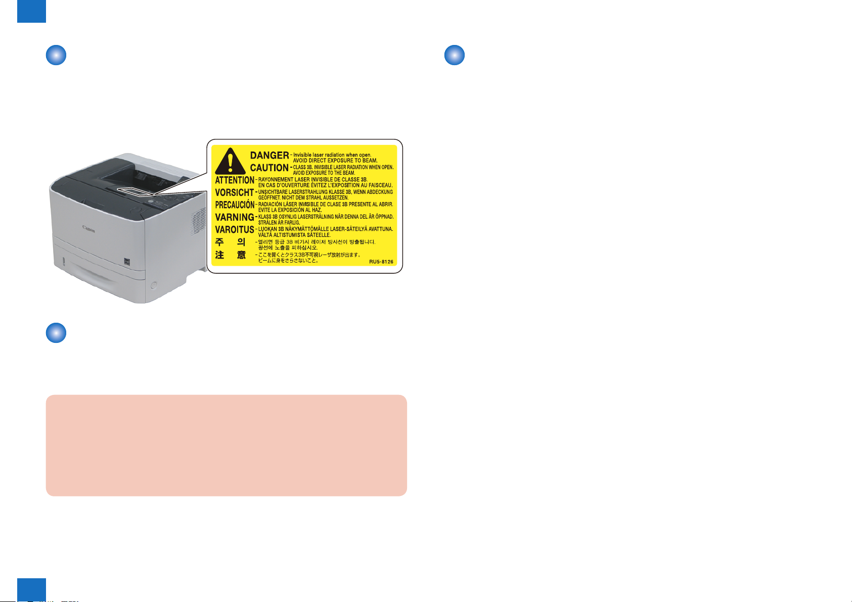
How to Handle the Laser Scanner Unit
An invisible laser beam is irradiated in the laser scanner unit.
If the laser beam enters an eye, it may cause damage to the eye. So, be sure not to
disassemble the laser scanner unit. No adjustment can be made to the laser scanner unit in
this machine in the eld.
The label shown in the following gure is attached to the bottom of the laser scanner unit.
F-0-3
Points to Note when Replacing/Discarding a Lithium
Points to Note when Performing Disassembly/Assembly
Be sure to follow the instruction shown below when performing disassembly/assembly.
1. Be sure to unplug the power plug for safety when performing disassembly/assembly.
2. If not otherwise specied, perform assembly in the procedure opposite to that of
disassembly.
3. Perform assembly using correct types of screws, etc. (length/diameter) at correct positions.
4. A washer screw is used as a screw to x a grounding wire and varistor, etc., to secure
electrical conduction. Be sure to use this screw when performing assembly.
5. In principle, do not operate the machine in the condition where parts are removed.
6. Do not remove a paint-locked screw when performing disassembly.
Battery
The main controller PCB in this machine contains a lithium battery as backup power supply
for various data just in the case when a blackout occurs or the power plug is removed.
CAUTION:
• The battery installed in this machine is xed and cannot be replaced.
• Do not replace the battery only.
• Replacing the battery with another type of battery can result in explosion.
• When disposing the old PCB with battery, remove the battery and follow the local
regulation.
Safety Precautions > Safety Information > Points to Note when Performing Disassembly/Assembly
0
0-11

Product
1
Description
Product Lineups
■
Features
■
List of Parts
■
Operation
■
Product Description
1
1
Product Description > Features
1-2
Product Lineups
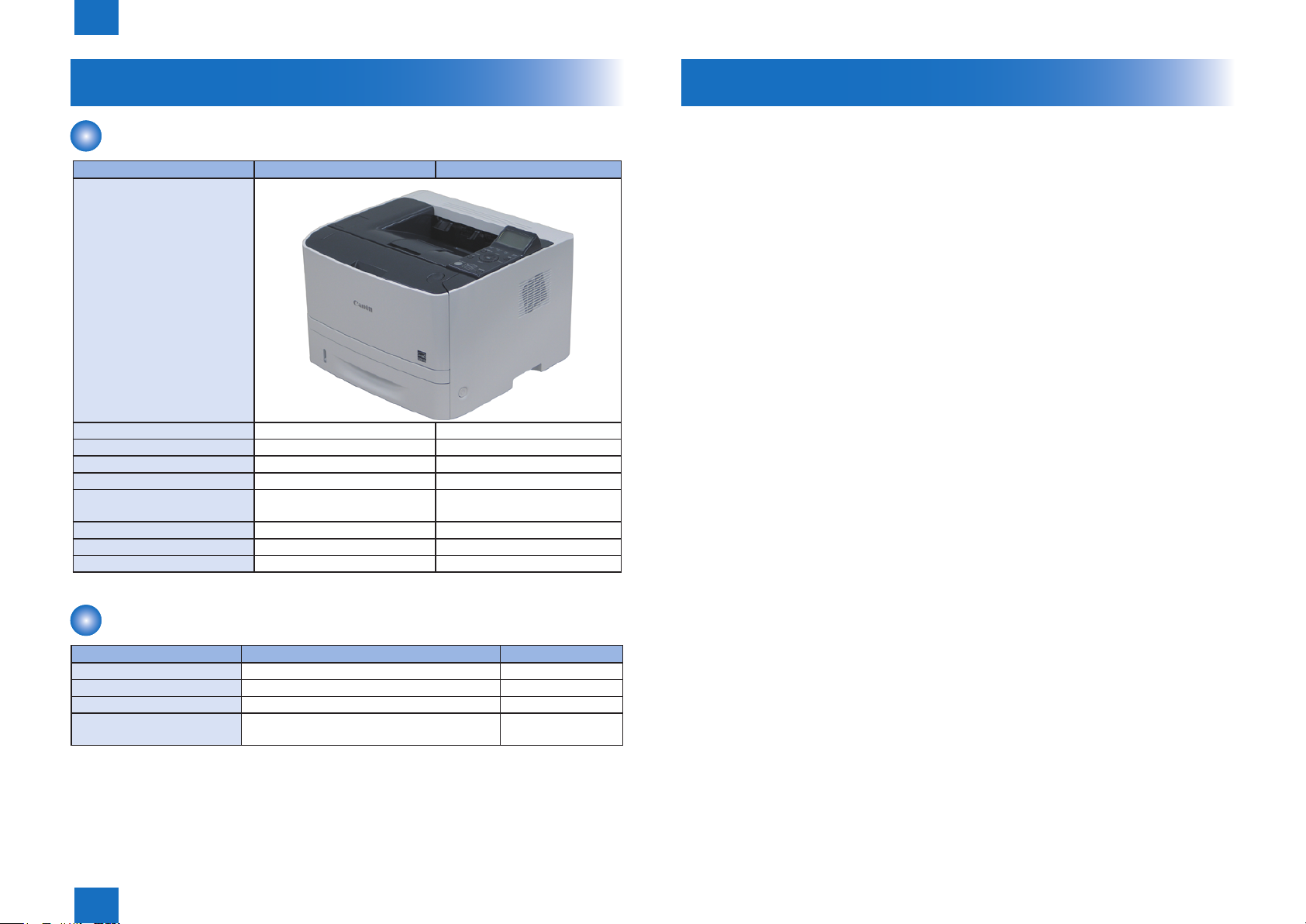
Main unit
Function LBP6670 LBP6680
Appearance
Copy x x
Print o o
FAX x x
Remote UI o o
Automatic 2-sided Print (60 to
120g / m2 paper)
MEAP x o
Network o o
WLAN x x
o o
Features
1. Small and high-speed printer
The printer is compact size that realizes print speed of approximately 35 pages per minute
on letter-size media and approximately 33 pages per minute on A4-size media by i-SENSYS
LBP6670dn/ imageCLASS LBP6670dn/ i-SENSYS LBP6680x/ imageCLASS LBP6680x, and
approximately 33 pages per minute on letter-size and A4-size media.
2. Automatic duplex print
Automatic two-sided printing is available with standard equipped duplex unit.
3. High-volume continuous printing
In addition to the standard equipped universal cassette (holds up to 250 sheets of 80g/m2
paper) and Multi-purpose tray (holds up to 50 sheets of 80g/m2 paper), the printer supports
optional paper feeder (holds up to 500 sheets of 80g/m2 paper) for a total capacity of 800
sheets. Thus high-volume continuous printing is available.
F-1-1
T-1-1
Options
Name Description Remarks
Paper FeederUnit PF-44 Approx. 500 Sheets (Plain paper 80g/ m2) PS Printer Kit-AQ1 EUR/CHN/KOR
Barcode Printing Kit-F1
SD CARD-B1 USA/ EUR/ AUS/
ASIA
Product Description > Features
1
T-1-2
1-2
1
Product Description > Specication > Printing Speed
1-3
Specication
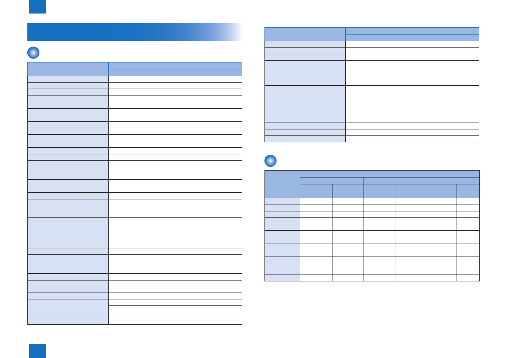
Product Specications
Item Specication/function
LBP6670 LBP6680
Installation Format Desktop type page printer
Photosensitive Element OPC drum
Exposure Principle Laser beam method
Development Principle Jumping development
Transfer Principle Roller transfer
Separation Principle Self stripping
Cassette Feed Principle Separate design
Multi Purpose Tray Principle Pad separation
Drum Cleaning Principle Rubber blade cleaning
Fixing Method On-demand
Paper Output Principle Face-down/Face-up
Toner Supply Principle Toner cartridgesNumber
Warm-up Time From power ON: max. 28 seconds
Recovery Time Approx. 10.0 seconds or less
Print Area Top 5.0 mm, Bottom 5.0 mm, Left/Right 5.0 mm
(Envelope: Top/Bottom/Left/Right 10.0 mm, Right 10.0 mm)
Printing Resolution 600 dpi
First Print Output Time Approx. 7.0 seconds or less
Printing Speed A4: 33 , LTR: 35 pages/minute
Cassette Paper Size Standard sizes: A4, B5, A5, A6, Legal, Letter, Executive
Custom size range (user-specied):
(Width 105.0 to 215.9 mm, Length 148.0 to 355.6 mm)
Multi Purpose Paper Size Standard sizes: A4, B5, A5, A6, Legal, Letter, Executive,
Postcard, Reply-paid Postcard, Four-side Postcard, Japanese
Western-style Envelope Size No. 3, Envelope Size No. 3
Custom size range (user-specied):
(Width 76.2 to 215.9 mm, Length 127.0 to 355.6 mm)
Cassette Paper Type Plain paper (60 to 90 g/m2), Heavy paper (91 to 120 g/m2),
Multi Purpose Paper Type Plain paper (60 to 90 g/m2), Heavy paper (91 to 163 g/m2),
OHP lm, label paper, postcard, envelope
Cassette Paper Capacity Approx. 250 sheets (Plain paper 80 g/m2)
Multi Purpose Paper Capacity Approx. 50 sheets (Plain paper 80 g/m2)
Output Tray Paper Capacity Face-down output: approx. 150 sheets (80 g/m2), face-up
output: 1 sheet
Duplex Printing Principle Auto Duplex
Interfaces USB: HI-Speed USB/USB2.0
Network: 10 Base-T/100BASE-T common (RJ-45)
Full duplex/half duplex
Memory Capacity Standard: 16 MB, Option: None
Item Specication/function
LBP6670 LBP6680
Hard Disk Capacity Standard: None, Option: None
Ambient Temperature Range for Use 10 to 30 degrees Celsius
Ambient Humidity Range for Use 20 to 80% RH
Operation Noise Level 53.5 dB or less (During printing: rated sound emission level
according to ISO9296)
Power Requirements 120 to 127V( +/- 10%), 50/60( +/- 2Hz)
220 to 240V( +/- 10%), 50/60( +/- 2Hz)
Max. Power Consumption 1060 W or less (120 V)
1140 W or less (230 V)
Power Consumption Average power consumption during operation: approx.
approx. 550 W (120 V), approx. 560 W (230 V)
Average power consumption during standby: approx. 13.2 W
(120 V), approx. 13.9 W (230 V)
Dimensions 400 (W) x 376 (D) x 289 (H) mm
Weight Printer main unit: approx. 11.6 kg (excl. toner cartridges)
Option Paper Feeder
Printing Speed
Face-down output
Cassette feed Manual tray feed OP cassette feed
Single-sided Duplex print Single-sided Duplex print Single-sided Duplex
print
A4 33 16.8 33 16.8 33 16.8
LTR 35 17 35 17 35 17
LGL 28.7 13.5 28.7 13.5 28.7 13.5
B5/EXE 13.7>12>8>6 16>12>8>6 10.7>8>6
A5 15.2>12>8>6 17>12>8>6 11.7>8>6
A6 17.3>12>8>6 17>12>8>6 13.2>12>8>6
16K 17>14 17>14
Strip (90 – 297
mm)
Envelope
(Japanese
Western-style)
Postcard 12>8>6>4
3
17>12>8>6
T-1-3
T-1-4
Product Description > Specication > Printing Speed
1
1-3
1
[3]
[4]
[5] [6]
[1]
[2]
[3]
[4]
[5]
[6]
[7]
[8]
[9]
Product Description > List of Parts > Cross Sectional View
1-4
List of Parts
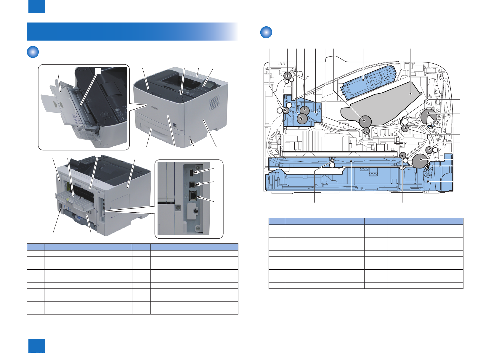
External View
[1]
[11] [13] [14]
[12]
[19]
No. Name No. Name
[1] Auxiliary Tray [11] Rear Cover
[2] Multi-purpose Tray [12] Face-up Output Tray
[3] Front Cover [13] Pressure Release Cover
[4] Open Button [14] Left Cover
[5] Upper Cover [15] USB Host
[6] Control Panel [16] USB Device
[7] Right Cover [17] LAN Port
[8] Power Switch [18] Duplex Unit Cover
[9] Face-down Output Tray Cover [19] Power Socket
[10] Paper Cassette
[18]
[2]
[10]
Cross Sectional View
[10]
[11]
[12]
[13]
[14]
[8][9]
[7]
[15]
[16]
[17]
T-1-5
[19][20]
No. Name No. Name
[1] Fixing Delivery Roller [11] Multi-purpose Tray Pickup Roller
[2] Face-down Delivery Roller [12] Multi-purpose Tray Separation Pad
[3] Pressure Roller [13] Registration Roller
[4] Fixing Film Unit [14] Feed Roller
[5] Fixing Unit [15] Cassette Pickup Roller
[6] Transfer Roller [16] Cassette Separation Pad
[7] Photosensitive Drum [17] Cassette
[8] Laser Scanner Unit [18] Duplex Re-pickup Roller
[9] Cartridge [19] Duplex Feed Unit
[10] Registration Shutter [20] Duplex Feed Roller
[18]
[15]
[16]
[17]
F-1-2
T-1-6
Product Description > List of Parts > Cross Sectional View
1
1-4
1
[1]
[2]
[3]
[4]
Product Description > Operation > Control panel
Operation
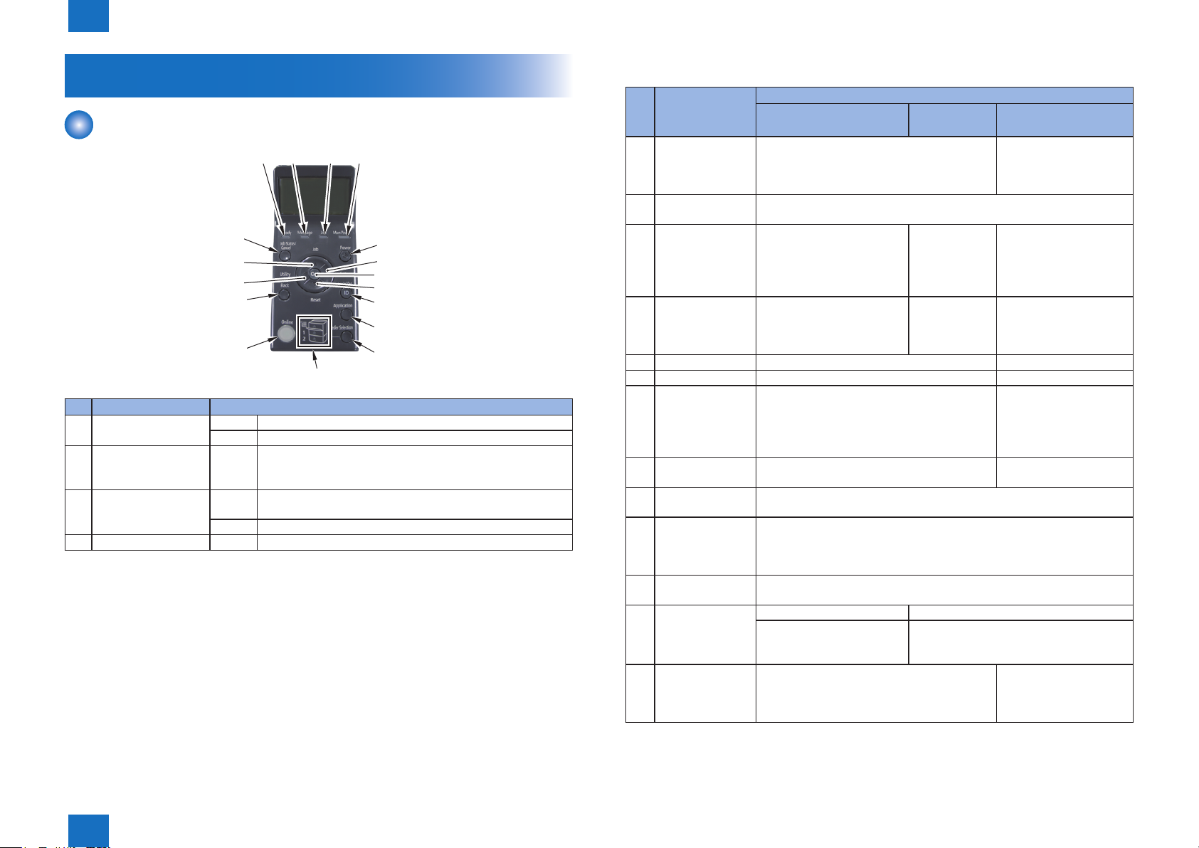
Control panel
[5]
[7]
[8]
[12]
[15]
[16]
No. Name Discription
[1] Ready Indicator On The printer is ready to print.
Blinking The printer is preparing to print.
[2] Message Indicator Blinking Aproblem has occurred and printing cannot be performed.
(If the printers Sleep Mode when it is ofine, the Message
indicator comes on even when no problem is occuring)
[3] Job Indicator On The printer is receiving data.
Data remains in the printer memory.
Blinking The printer is processing data.
[4] Main Power Indicator On The power of the printer is ON.
[6]
[9]
[10]
[11]
[13]
[14]
[17]
F-1-3
T-1-7
1-5
No. Name Function
When the printer is online When the
printer is ofine
[5] Status/Cancel Key If pressed when the Job indicator is on or
blinking (When data is being processed or
received), diaplay the job list. Select a job from
the list to cancel the job.
[6] Power Key If [Sleep Mode] is set to a setting other than [Off], the printer enters Sleep
Mode.
[7] Job Key Displays the [Job] menu. You
can print various log list.
[8] Utility Key Display the [Utility Menue]
menu. Prints information
about the printer settings
including the current settings.
[9] Settings Key Displays the [Setup] menu. Gose down the hierarchy
[10] OK Key Does not function. Gose down the hierarchy
[11] Reset Key Display the [Reset] menu. Performs the printer
reset operation, the print data output, and the
shutdown operation.
[12] Back Key Does not function. Goes back up the
[13] Log In/Out Key The log in screen for using MEAP functions is displayed. Enter the Dept.
ID/PIN and log in to the printer.
[14] Application Key It will transition to the Menu Screen. Whenever the key is pressed, the
Printing Screen switches to → MEAP Application 1 → MEAP Application
2.Meap Application 8 → USB Direct Print → Printing Screen → Menu
Screen
[15] Online Key Switches between online and ofine . The printer is online when the
indicator under the key is on and is ofine when the indicator is off.
[16] Paper Source
Indicator
[17] Feeder Selection
Key
On A paper source is selected.
Blinking Printing cannot be performed because no
Displays the [Select Feeder] menu. Specify
which paper source is used to print between
the paper drawer and multi-purpose tray and
the paper size.
Does not
function.
Does not
function.
paper is loaded.
The paper drawer is not installed.
When the menu is
displayed
Does not function.
Select the next upper item
in the same hierarchy.
When the setting value
is numeric, increase the
value.
Goes back up the
previous hierarchy.
Select the next lower item
in the same hierarchy.
When the setting value
is numeric, reduces the
value.
previous hierarchy.
Does not function.
T-1-8
Product Description > Operation > Control panel
1
1-5

Technology
2
Basic Operation
■
Sequence of Operation
■
Laser Exposure System
■
Image Formation System
■
Fixing System
■
Pickup Feeding System
■
Controller System
■
MEAP
■
Embedded RDS
■
2
Technology

2
Technology > Sequence of Operation > Outline
2-2
Basic Operation
Function Structure
The function structure of the printer contains the following ve systems:
• Engine control system
• Laser scanner system
• Image-formation system
• Media feed system
• Option
LASER SCANNER SYSTEM
IMAGE-FORMATION SYSTEM
ENGINE CONTROL
SYSTEM
MEDIA FEED SYSTEM
OPTION
F-2-1
Sequence of Operation
Outline
The operation sequence is controlled by the DC Controller in the engine control system.
Operations for each period of a print operation from the machine is turned on until the motor
stops rotating are described below.
Period Duration Operation
WAIT From the time power switch is
turned on or the dooe is closed
unitil the printer gets ready for a
print operation.
STBY
(Standby)
INTR
(Initial rotation)
PRINT From the end of INTR period unit
LSTR
(Last rotation)
From the end of WAIT or LSTR
period until either the print
command is received the main
controller or the power switch is
turned off.
From the time print command is
received from the main controller
unit the temperature of the
xing unit reaches its targeted
temperature.
the last media completes the xing
operation.
From the end of PRINT period unit
the motor stops rotationg.
Brings the printer to printable condition.
The rpinter performs the following during this
period:-Detects cartridge presence.
Maintains the printer in printable condition.
Starts up each high-voltage biases, laser
scanner and xing unit in preparing for print
operation.
Forme the image on the photosensitive drum
based on the VIDEO signals from the main
controlloer.
Transfers and fuses the toner image to the
print media.
Moves the last printed sheet out of the printer.
Stops laser scanner operation and highvoltage biases output.
The printer enters INTR period as the LSTR
period is completed if the main controller
sends another print command.
T-2-1
Technology > Sequence of Operation > Outline
2
2-2
2
Engine controller
Technology > Laser Exposure System > Optical Unit Failure Detection
2-3
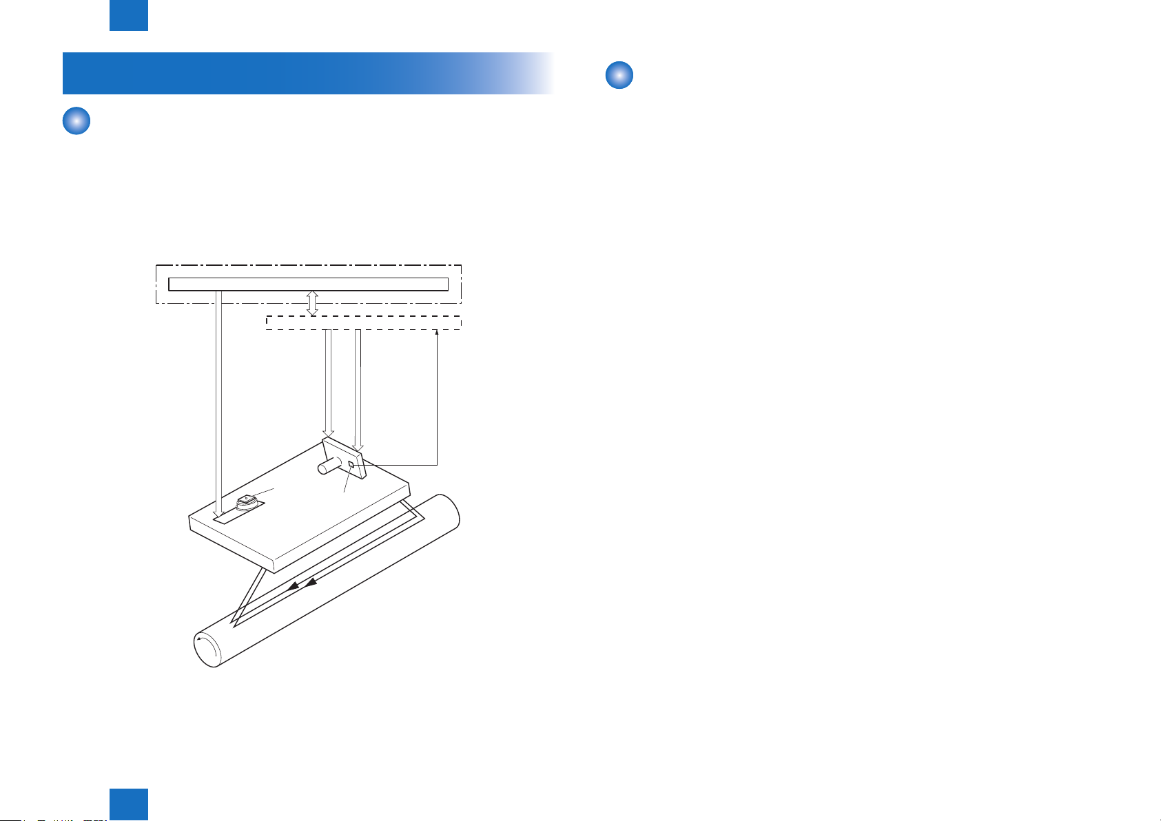
Laser Exposure System
The laser exposure system forms a latent image on the photosensitive drum according to the
VIDEO signalssent from the Main Controller.
The main components of the laser scanner are the laser unit and the scanner motor unit,
which arecontrolled by the signals sent from the DC controller.
Diagram of the Laser Scanner Unit is shown below.
Outline
DC controller
Main controller
VIDEO signal
LASER CONTROL signal
Laser unit
SCANNER MOT OR SPEED CONTROL signal
Scanner mirror
BD sensor
Optical Unit Failure Detection
The optical unit failure detection manages the laser scanner failure detection functions.
The DC controller determines an optical unit failure and noties E100 to the Main controller if
the laser scanner encounters the following conditions:
• If the scanner motor does not reach a specied rotation within a specied period of start-up.
• If the rotation of the scanner motor is out of specied range for a specied period during
drive.
• If an out of specied BD interval is detected during a print operation.
BD INPUT signal
Scanner motor unit
Photosensitive drum
Technology > Laser Exposure System > Optical Unit Failure Detection
2
F-2-2
2-3
2
Laser scanner
Media path
Technology > Image Formation System > Image Formation Process > Outline
2-4
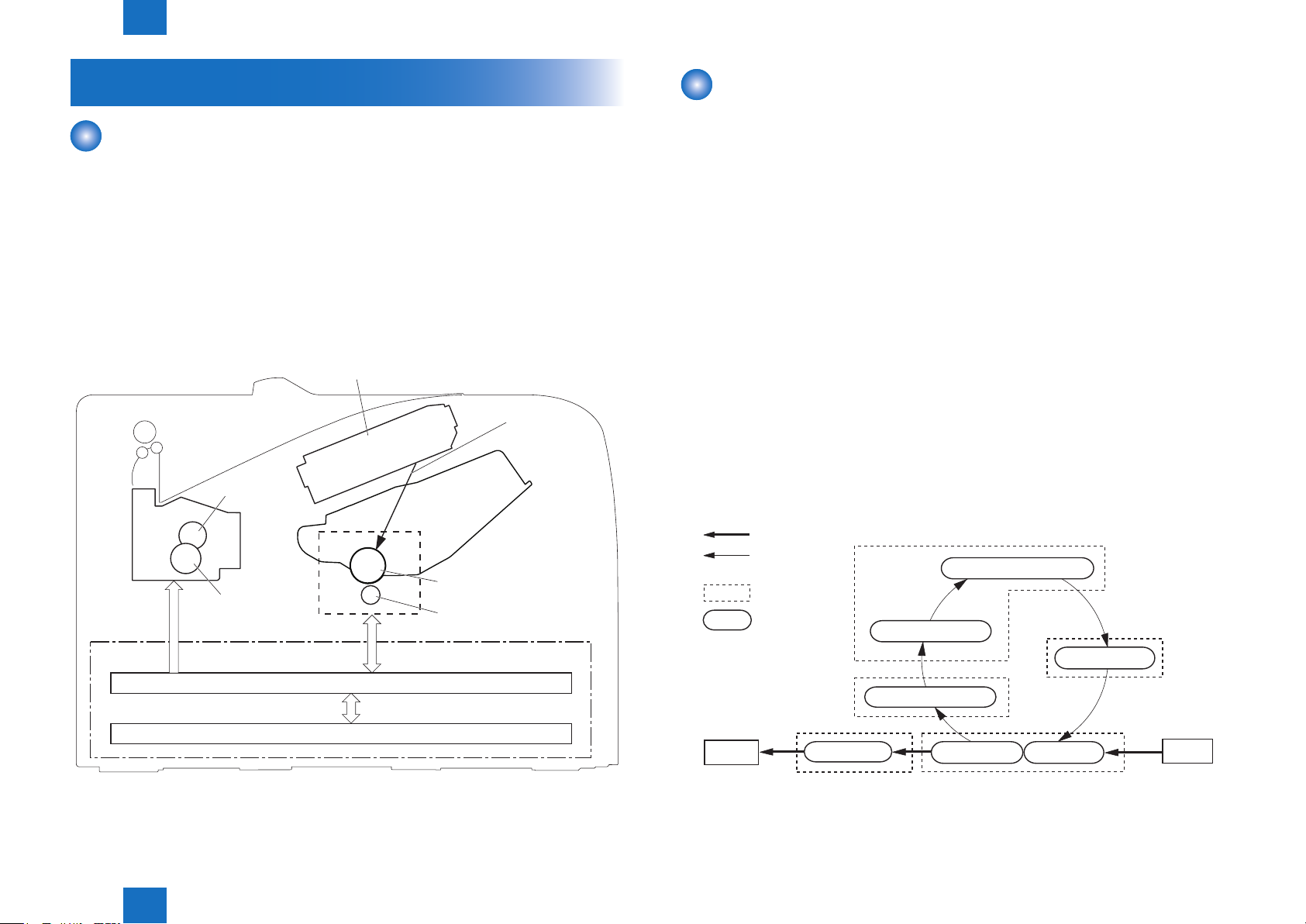
Image Formation System
Outline
The image formation system forms a toner image on print media.
The following are the main components of the image formation system:
• Cartridge
• Transfer roller
• Fixing unit
• Laser scanner\
The DC controller controls the laser scanner and high-voltage power supply to form the toner
imageon the photosensitive drum. The image is transferred to the print media and xed.
Diagram of the image formation system is shown below.
Laser beam
Cartridge
Photosensitive drum
Transfer roller
Engine controller
Fixing unit
Fixing film
Pressure roller
High-voltage power supply
Image Formation Process
■
Outline
The image formation process consists of the following seven steps divided among ve
functional blocks:
Latent image formation block
Step 1: Primary charging
Step 2: Laser-beam exposure
Developing block
Step 3: Developing
Transfer block
Step 4: Transfer
Step 5: Separation
Fixing block
Step 6: Fixing
Drum cleaning block
Step 7: Drum cleaning
Latent image formation
Direction of
the drum rotation
Block
Step
1. Primary charging
Drum cleaning
7. Drum cleaning
2. Laser-beam exposure
Developing
3. Developing
DC controller
Technology > Image Formation System > Image Formation Process > Outline
2
F-2-3
6. FixingDelivery
Fixing
Transfer
Pickup4.Transfer5. Separation
F-2-4
2-4

2
Primary charging roller
Laser beam
Technology > Image Formation System > Image Formation Process > Developing block
2-5
■Latent image formation block
During the two steps that comprise this block, an invisible latent image is formed on the
photosensitivedrum.
Step 1: Primary charging
To prepare for latent image formation, the surface of the photosensitive drum is charged
with a uniform negative potential. The primary charging bias is applied to the primary
charging roller and the roller charges the drum directly.
Photosensitive drum
Step 2: Laser-beam exposure
The laser beam scans the photosensitive drum to neutralize the negative charge on
portions of the drum surface. An electrostatic latent image forms where the negative charge
was neutralized.
Primary charging bias
F-2-5
■Developing block
Toner adheres to the electrostatic latent image on the photosensitive drum, which becomes
visible.
Step 3: Developing
Toner acquires a negative charge from the friction that occurs when the developing roller
rotates against the developing blade. The negatively charged toner is attracted to the
latent image on the photosensitive drum surface because the drum surface has a higher
potential. The developing bias is applied to the developing roller.
Blade
Developing rolle
Exposed
area
Unexposed
area
Photosensitive drum
Unexposed
area
Exposed
area
Developing bias
F-2-7
2
Unexposed area Exposed area
F-2-6
2-5
Technology > Image Formation System > Image Formation Process > Developing block
2
Fixing film
Fixing heater
Cleaning blade
Technology > Image Formation System > Image Formation Process > Drum cleaning block
2-6
■Transfer block
During the two steps that comprise this block, a toner image on the photosensitive drum is
transferred to the print media.
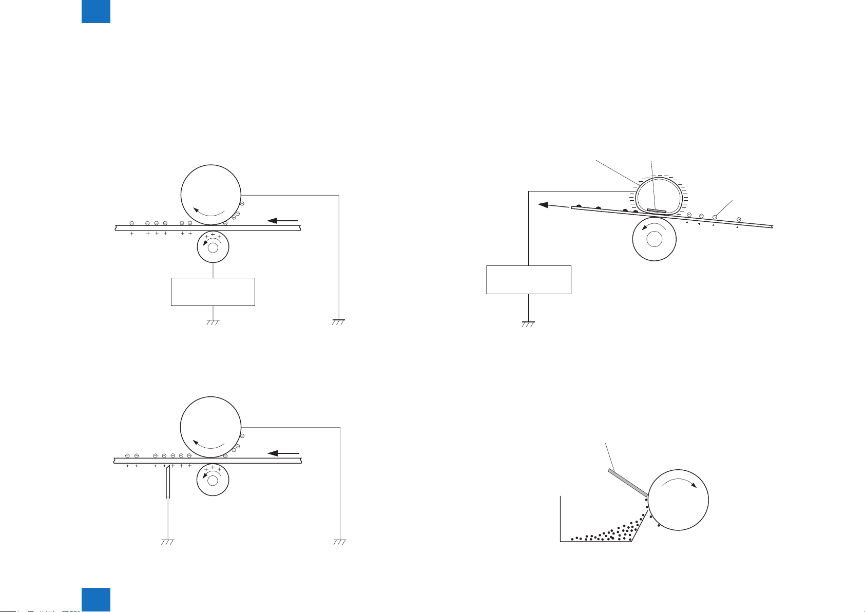
Step 4: Transfer
The transfer bias is applied to the transfer roller to charge the print media positive. The
positively charged media attracts the negatively charged toner from the photosensitive
drum surface.
Photosensitive
drum
Media
Transfer roller
Transfer bias
F-2-8
Step 5: Separation
The elasticity of the print media and the curvature of the photosensitive drum cause the
media to separate from the drum surface. The static charge eliminator reduces back side
static discharge of the media for stable media feed and image quality.
Photosensitive
drum
■Fixing block
The toner image is xed onto the print media.
Step 6: Fixing
The printer uses an on-demand xing method. The toner image is permanently afxed to
the print media by heat and pressure. The xing bias is applied to the xing lm to improve
image quality.
Toner
Media
Pressure roller
Fixing bias
F-2-10
■Drum cleaning block
The residual toner is cleared from the photosensitive drum surface.
Step 7: Drum cleaning
The cleaning blade scrapes the residual toner off the surface of the photosensitive drum.
The residual toner is deposited in the toner collection box.
Media
Static charge
eliminator
Technology > Image Formation System > Image Formation Process > Drum cleaning block
Transfer roller
F-2-9
2
Toner
collection box
Photosensitive
drum
F-2-11
2-6
2
Engine controller
Technology > Image Formation System > High-voltage Power Supply > Outline
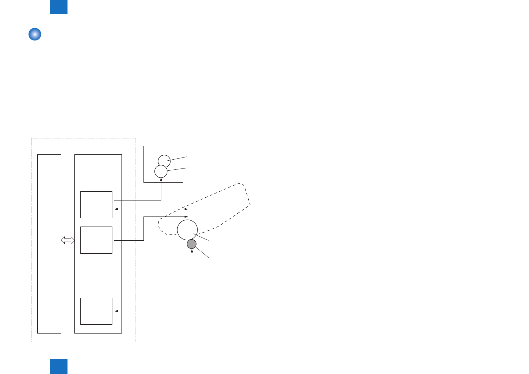
High-voltage Power Supply
■Outline
The high-voltage power supply applies biases to the following components:
• Primary charging roller
• Developing roller
• Transfer roller
• Fixing lm
The DC controller controls the high-voltage power supply to generate biases. See "IV.
IMAGE-FORMATION SYSTEM"(Refer to page 2-4)for detailed information.
The Figure below shows the conguration of the High-voltage Power Supply.
2-7
DC controller
High-voltage
power supply
Primary
charging
bias circuit
Developing
bias circuit
Transfer
bias circuit
FB
PR
DV
TR
Fixing unit
Fixing film
Pressure roller
Cartridge
Primary charging roller
Developing roller
Photosensitive
drum
Transfer roller
Technology > Image Formation System > High-voltage Power Supply > Outline
2
F-2-12
2-7
2
Technology > Fixing System > Outline
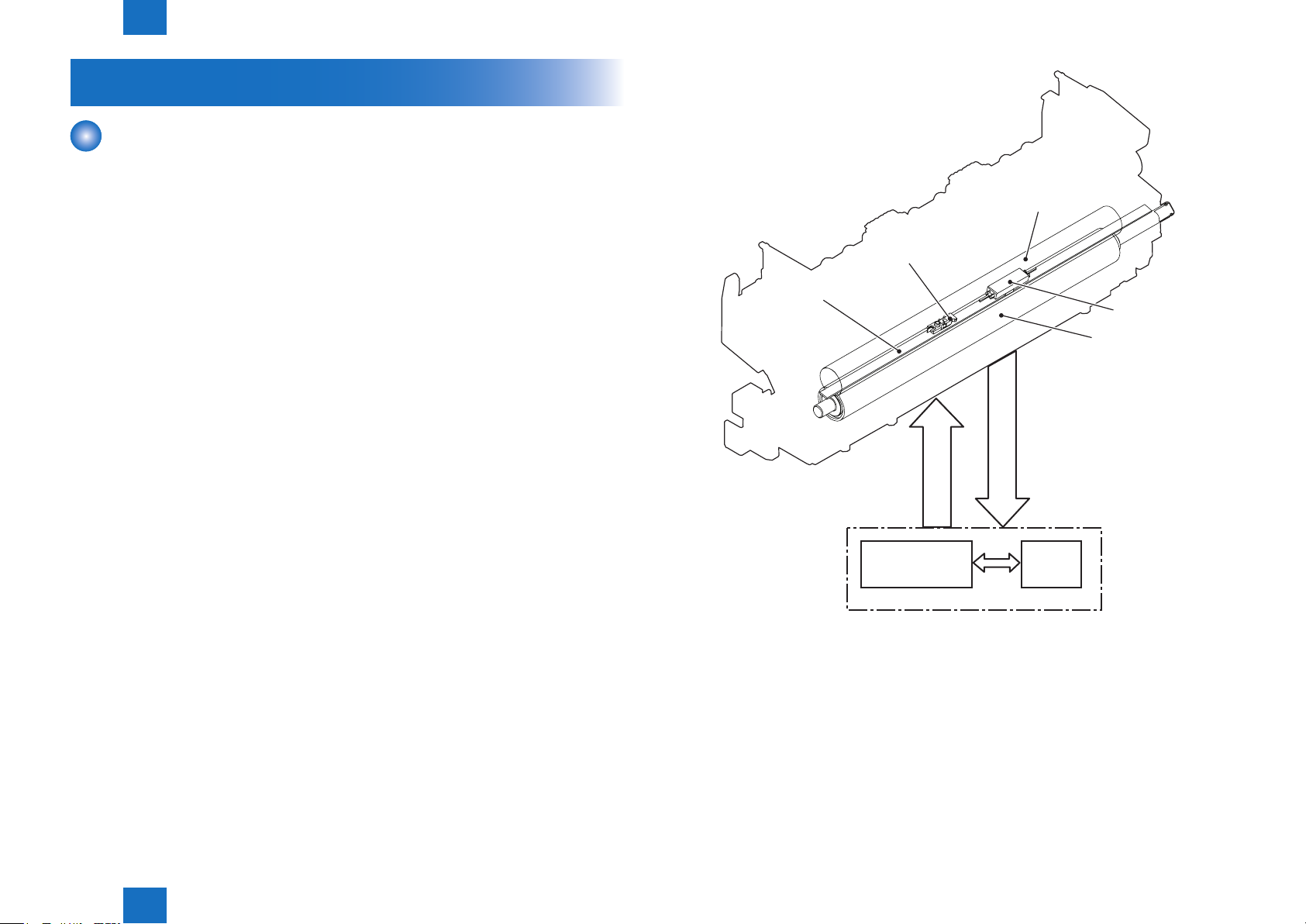
Fixing System
Outline
The xing/delivery unit xes the toner onto a print paper and delivers it to the delivery tray.
The operation of the xing/delivery unit is explained in the following.
1) The print paper fed from the pick-up/feed unit is fused the toner by the xing lm and the
pressure roller.
2-8
Fixing unit
Fixing film
2) The print paper delivered from the xing unit is delivered to the face-down delivery tray or
the face-up delivery slot. When the engine controller detects that the heater temperature
reaches 50 deg C after the last rotation is completed, it drives the main motor for 50 msec.
and dislocates the nip part. This prevents the toner adhering to the pressure roller.
The xing unit of this printer utilizes the on-demand xing method. It is structured as shown
below.
- Heater:
This xing unit incorporates one heater.
Fixing heater (H1): To heat the xing lm (ceramic heater)
- Thermistor:
This xing unit incorporates one thermistor.
Thermistor (TH1): Sit almost at the center of the xing lm. (contact type)
To control the temperature of the xing lm
- Thermal switch:
Thermoswitch (TP1): Sit almost at the center of the xing lm (contact type)
If the temperature of the heater rises abnormally high, the contact gets broken and
cuts off the AC voltage supply to the xing heater to interrupt the power supply to the
heater.
The temperature control of the xing unit incorporated as above is operated by the xing
temperature control circuit according to the command from the CPU (IC201) on the DC
controller.
The followings describe the each circuit and function of the temperature control of the xing
unit.
Fixing heater
Thermistor
Fixing heater
control circuit
FIXING TEMPERATURE
DETECTION signal
FIXNG HEATER
CONTROL signal
Engine controller PCB
Thermoswitch
Pressure roller
CPU
F-2-13
Technology > Fixing System > Outline
2
2-8
2
Technology > Fixing System > Fixing control circuit > Small Size Paper Printing Speed Control (Throughput Reduction Control)
2-9
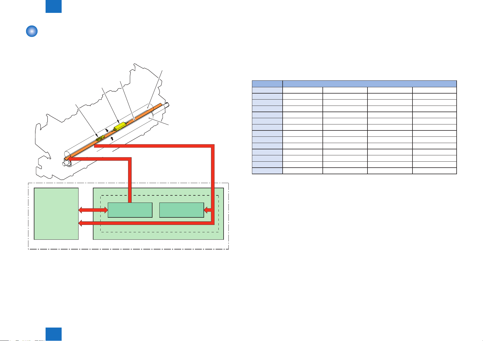
Fixing control circuit
The xing control circuit controls the temperature in the xing unit. The printer uses an ondemand xing method.
The Figure below shows the conguration of the xing control circuit.
Fixing film
H1
TP1
TH1
Pressure roller
FIXING TEMPERA TURE signal
FIXNG HEATER CONTROL signal
■Small Size Paper Printing Speed Control (Throughput
Reduction Control)
During continuous printing, the throughput is changed to reduce heat buildup on parts not in
contact with paper, to improve xing characteristics and reduce curling.
The throughput reduction is implemented according to the following conditions.
Fixing Mode Throughput
Envelope 1 – 23 imprints 23 – 39 imprints 40 – 47 imprints 48 imprints or more
17 ppm 12 ppm 8 ppm 6 ppm
Envelope 2 1 – 27 imprints 28 – 62 imprints 63 – 174 imprints 175 imprints or more
17 ppm 12 ppm 8 ppm 6 ppm
Envelope 3 1 – 31 imprints 32 – 47 imprints 48 – 79 imprints 80 imprints or more
12 ppm 8 ppm 6 ppm 4 ppm
Postcard 1 – 31 imprints 32 – 47 imprints 48 imprints or more
12 ppm 8 ppm 6 ppm
16K 1 – 89 imprints 90 imprints or more
16 ppm 14 ppm
16K Rough 1 – 34 imprints 35 imprints or more
16 ppm 8 ppm
Long Narrow 1 imprint or more
3 ppm
T-2-2
DC controller
• Fixing heater (H1): Heats the xing lm
• Thermistor (TH1): Detects xing temperature (Contact type)
• Thermoswitch (TP1):Prevents an abnormal temperature rise of the xing heater
(Contact type)
These temperature controls in the xing unit are performed by the xing heater control circuit
and the xing heater safety circuit according to the commands from the DC controller.
Technology > Fixing System > Fixing control circuit > Small Size Paper Printing Speed Control (Throughput Reduction Control)
Fixing heater
control circuit
Fixing control circuit
Low-voltage power supply unit
Engine controller
Fixing heater
safety circuit
F-2-14
2
2-9
2
Technology > Fixing System > Fixing control circuit > Protective function
2-10
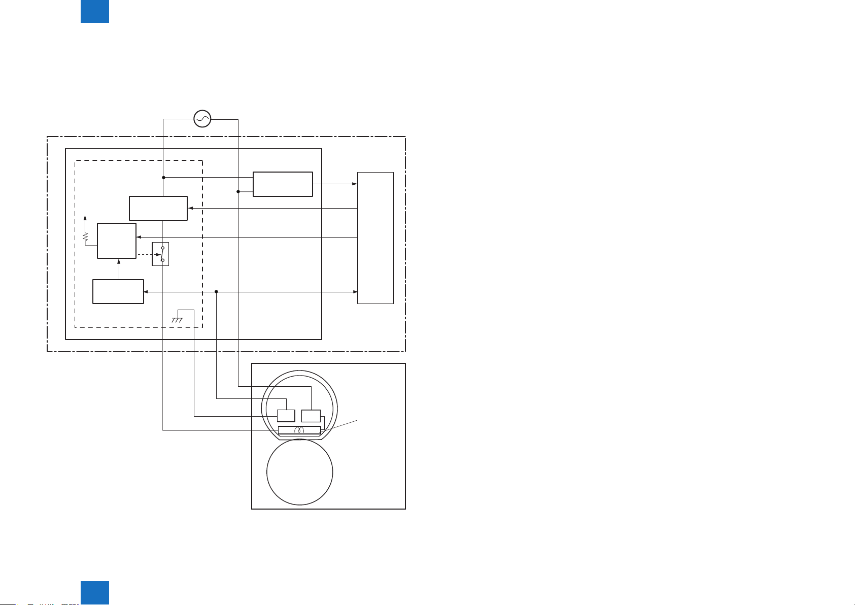
■Fixing temperature control
The xing temperature control maintains the temperature of the xing heater at its targeted
temperature.
Block diagram of this control is shown below.
Engine controller
Low-voltage power supply
Fixing control circuit
+24V
Fixing heater
safety circuit
Fixing heater
control circuit
Relay
control
circuit
Frequency
detection circuit
RL101
DC controller
FREQSNS
FSRD
RLYD
FSRTH
heater control circuit controls the xing heater depending on the signal so that the heater
remains at the targeted temperature.
■Protective function
The protective function detects an abnormal temperature rise in the xing unit and interrupts
power supply to the xing heater.
The following three protective components prevent an abnormal temperature rise of the xing
heater:
• DC controller
• Fixing heater safety circuit
• Thermoswitch
1) Thermoswitch
The contact of the thermoswitch is broken to interrupt power supply to the xing heater
under the following condition:
• Temperature fuse: 228°C (442.4°F) or higher
2) DC controller
The DC controller monitors the detected temperature of the thermistor. The DC controller
makes the FIXING HEATER CONTROL signal inactive and releases the relay to interrupt
power supply to the xing heater under the following condition:
• Thermistor: 240°C (464°F) or higher
Fixing film unit
TH1 TP1
Pressure roller
The DC controller monitors the FIXING TEMPERATURE (FSRTH) signal and sends the
FIXING HEATER CONTROL (FSRD) signal according to the detected temperature. The xing
Technology > Fixing System > Fixing control circuit > Protective function
H1: Fixing heater
TP1: Thermoswitch
TH1: Thermistor
Fixing unit
F-2-15
2
3) Fixing heater safety circuit
The xing heater safety circuit monitors the detected temperature of the thermistor.
The xing heater safety circuit releases the relay control circuit to interrupt power supply
to the xing heater under the following condition:
• Thermistor: 270°C (518°F) or higher
2-10

2
Technology > Fixing System > Fixing control circuit > Failure detection
■Failure detection
The DC controller determines a xing unit failure, makes the FIXING HEATER CONTROL
signal inactive, releases the relay to interrupt power supply to the xing heater and noties
the Main Controller of a failure state when it encounters the following conditions:
1) Start-up failure (E000)
• If the detected temperature of the thermistor is kept a specied degrees or higher for a
specied period of heater start-up during the wait period.
• If the detected temperature of the thermistor is kept a specied degrees or lower for a
specied period under the heater temperature control during the initial rotation period.
• If the detected temperature of the thermistor is kept a specied degrees or lower for a
specied period under the heater temperature control during the print period.
• If the detected temperature of the thermistor does not reach its targeted temperature within
a specied period under the heater temperature control during the initial rotation period.
2) Abnormal high temperature (E001)
• If the detected temperature of the main thermistor is kept a specied degrees or higher for
a specied period.
3) Abnormal low temperature (E003)
• If the detected temperature of the thermistor is kept a specied degrees or lower for a
specied period under the heater temperature control.
2-11
4) Drive circuit failure (E004)
• If a specied frequency of the FREQUENCY signal is not detected within a specied period
after the printer is turned on.
• If an out of specied frequency of the FREQUENCY signal is detected after the printer is
turned on and the signal is once detected.
Technology > Fixing System > Fixing control circuit > Failure detection
2
2-11
2
Technology > Pickup Feeding System > Outline
2-12
Pickup Feeding System
Outline
The pickup feeding system picks up, feeds and delivers the print media. It consists of several
types of rollers.
The duplex feed unit in the duplex model reverses and refeeds the print media to print on
both sides of media.
The media path is shown below.
Face-down delivery roller
Fixing film
Pressure
roller
Fixing delivery roller
: Simplex media path
: Duplex media path
Photosensitive drum
Duplex feed roller
Transfer roller
Duplex re-pickup roller
Cassette pickup roller
Registration roller
MP tray separattion roller
MP tray
separattion pad
Cassette
separation pad
F-2-16
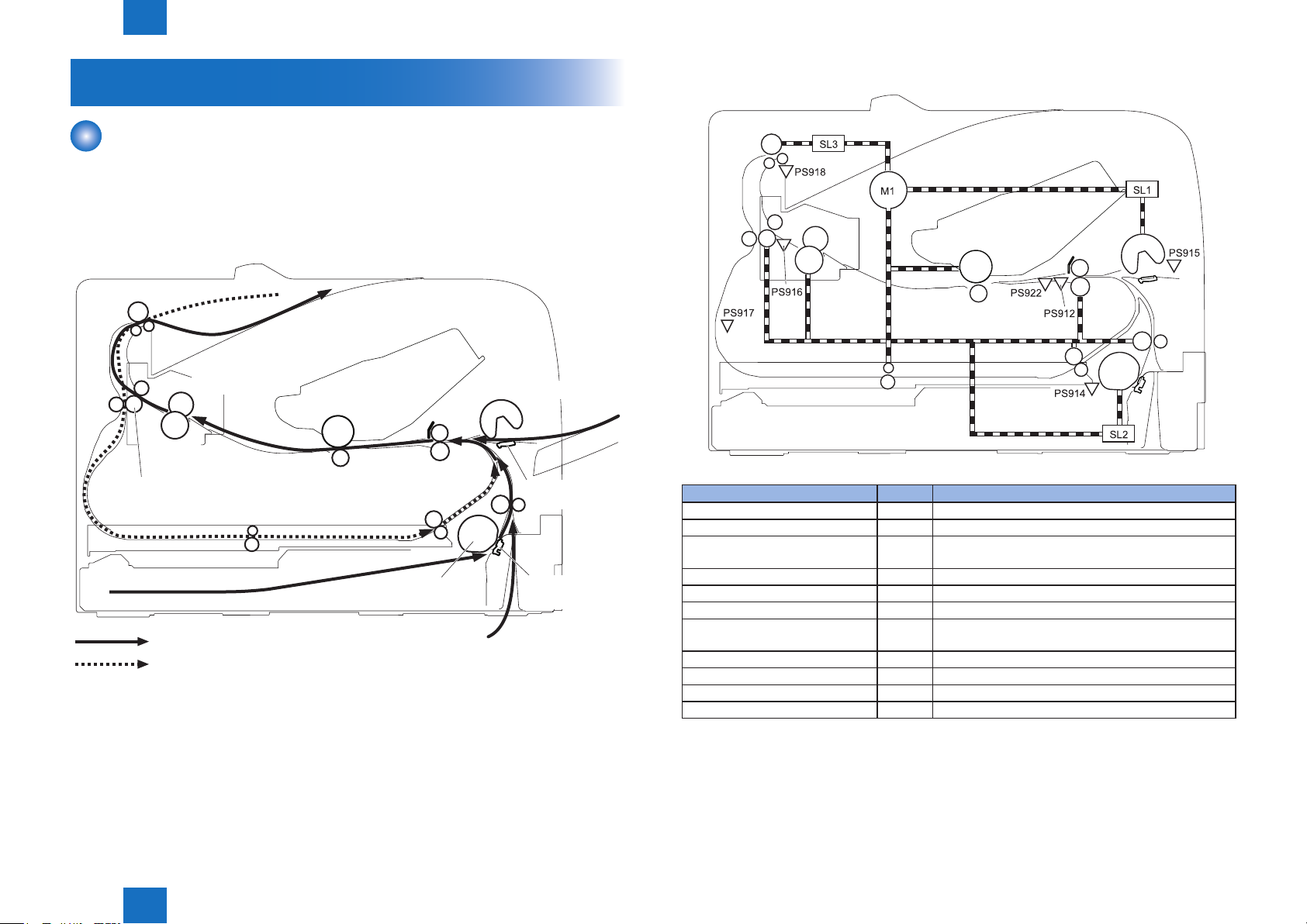
Diagram and table of the electrical components are shown below.
Electrical component Signal
Main Motor M1 Main Motor Control Signal
Cassette Pickup Solenoid SL1 Cassette Pickup Solenoid Control Signal
Multi-purpose Tray Pickup
Solenoid
Duplex Revrse Solenoid SL3 Duplex Reverse Solenoid Control Signal
TOP Sensor PS912 TOP Signal
Cassette Media Presence Sensor PS914 Cassette Media Presence Signal
Multi-purpose Tray Presence
Sensor
Fixing Delivery Sensor PS916 Fixing Delivery Signal
Duplex Reverse Sensor PS917 Duplex Reverse Signal
FD Tray Media Full Sensor PS918 FD Tray Media Full Signal
Media Width Sensor PS922 Media Width Signal
SL2 Multi-purpose Tray Pickup Solenoid Control Signal
PS915 Multi-purpose Tray Media Presence Signal
F-2-17
T-2-3
Technology > Pickup Feeding System > Outline
2
2-12

2
Technology > Pickup Feeding System > Jam Detection > Reverse Delay Jam
2-13
Jam Detection
■
Outline
The printer uses the following sensors to check whether media is being fed correctly or has
jammed:
• TOP sensor (PS912)
• Fixing delivery sensor (PS916)
• Duplex reverse sensor (PS917)
• Media width sensor (PS922)
PS916
PS917
PS922 PS912
■Pickup Delay Jam
When the TOP Sensor (PS912) cannot detect the leading edge of paper within the specied
time after starting pickup from a cassette, pickup retry is executed twice. After that, the sensor
still cannot detect the leading edge of paper within the specied time, it is judged as a pickup
jam.
■Pickup Stationary Jam
When the TOP Sensor (PS912) cannot detect the trailing edge of paper after the specied
time has passed since it detected the leading edge of paper, it is judged as a pickup
stationary jam.
■Delivery Delay Jam
When the Fixing Delivery Sensor (PS916) cannot detect the leading edge of paper after the
specied time has passed since the TOP Sensor (PS912) detected the leading edge of paper,
it is judged as a delivery delay jam.
■Fixing Paper Wrap Jam
After judging that it is not a delivery delay jam, execute the detection of xing paper wrap jam.
It is judged as a xing paper wrap jam when all of the following conditions are met: after the
specied time had passed since the Fixing Delivery Sensor (PS916) detected the leading
edge of paper, after the specied time had passed since the TOP Sensor (PS912) detected
the leading edge of paper, and the Fixing Delivery Sensor (PS916) detects no paper.
: Simplex media path
: Duplex media path
Technology > Pickup Feeding System > Jam Detection > Reverse Delay Jam
2
F-2-18
■Delivery Stationary Jam
After judging that it is not a xing paper wrap, execute the detection of delivery stationary jam.
When the Fixing Delivery Sensor (PS916) does not detect no paper within the specied time
since the TOP Sensor (PS912) detected the trailing edge of paper, it is judged as a delivery
stationary jam.
■Reverse Delay Jam
After judging that it is not a delivery stationary jam, execute the detection of reverse stationary
jam.
When the Duplex Reverse Sensor (PS917) does not detect paper after the specied time
has passed since the Fixing Delivery Sensor (PS916) detected the trailing edge of paper, it is
judged as a reverse delay jam.
2-13

2
Technology > Pickup Feeding System > Jam Detection > Door Open Jam
■Reverse Stationary Jam
When the Duplex Reverse Sensor (PS917) cannot detect the trailing edge of paper after the
specied time has passed since the sensor detected the leading edge of paper, it is judged
as a reverse stationary jam.
■Internal Residual Jam
When a paper is detected by the TOP Sensor (PS912), Fixing Delivery Sensor (PS916),
Paper Width Sensor (PS922), or Duplex Reverse Sensor (PS917) at the time of starting initial
rotation, it is judged as an internal residual jam.
■Door Open Jam
When a door-open is detected while feeding papers, it is judged as a door open jam.
2-14
Technology > Pickup Feeding System > Jam Detection > Door Open Jam
2
2-14
 Loading...