

Canon lbp2410 Service Manual

LBP-2410
REVISION 0
FEB.2003
COPYRIGHT© 2003 CANON INC. 2000 2000 20000 CANON LBP-2410 REV.0 FEB. 2003 PRINTED IN JAPAN (IMPRIME AU JAPON)
FY8-13HX-000

Application
This manual has been issued by Canon Inc. for qualified persons to learn technical
theory, installation, maintenance, and repair of products. This manual covers all
localities where the products are sold. For this reason, there may be information in this
manual that does not apply to your locality.
Corrections
This manual may contain technical inaccuracies or typographical errors due to
improvements or changes in products. When changes occur in applicable products or in
the contents of this manual, Canon will release technical information as the need arises.
In the event of major changes in the contents of this manual over a long or short period,
Canon will issue a new edition of this manual.
The following paragraph does not apply to any countries where such provisions are
inconsistent with local law.
Trademarks
The product names and company names used in this manual are the registered
trademarks of the individual companies.
Copyright
This manual is copyrighted with all rights reserved. Under the copyright laws, this
manual may not be copied, reproduced or translated into another language, in whole or
in part, without the written consent of Canon Inc.
COPYRIGHT © 2003 CANON INC.
Printed in Japan
Imprimé au Japon
Caution
Use of this manual should be strictly supervised to avoid disclosure of confidential information.
COPYRIGHT© 2003 CANON INC. 2000 2000 2000 CANON LBP-2410 REV.0 FEB. 2003 PRINTED IN JAPAN (IMPRIME AU JAPON)

INTRODUCTION
INTRODUCTION
This Service Manual provides basic facts and figures needed to service the Laser Beam
Printer LBP-2410 (hereafter, the machine or the printer) in the field. It also contains descriptions of the 250-sheet paper feeder available for the machine.
This Service Manual consists of the following chapters:
Chapter 1 Outline of the Product: features, specifications, installation, how to operate the
machine
Chapter 2 Outline of Operations: principles of mechanical/electrical operations according to
functions; timing of operations
Chapter 3 Mechanical System: mechanical construction, disassembly/assembly and adjust-
ments
Chapter 4 Troubleshooting: corrective measures; standards, adjustments, maintenance/in-
spection
Appendix: general timing chart, general circuit diagrams, list of signals
The descriptions herein are subject to change for product improvement or the like, and
major changes will be communicated in the form of Service Information bulletins.
All service persons are expected to go through the contents of this document and the applicable Service Information bulletins and be fully familiar with the machine, thereby equipping themselves with the knowledge and skill needed to maintain its quality and performance.
COPYRIGHT
©
2003 CANON INC. 2000 2000 2000 2000 CANON LBP-2410 REV.0 FEB. 2003
i

CONTENTS
Contents
CHAPTER 1 PRODUCT INFORMATION
1 FEATURES ...................................... 1-1
1.1.1 Compact color printer .......... 1-1
1.1.2 Reduced wait time and low
power consumption ............. 1-1
1.1.3 EP-87 DRUM
CARTRIDGE ...................... 1-1
1.1.4 Employment of Canon
Advanced Printing
Technology .......................... 1-1
2 SPECIFICATIONS .......................... 1-2
2.1 Printer......................................... 1-2
2.1.1 Printer engine ....................... 1-2
2.1.2 Interface controller .............. 1-3
2.2 Options ....................................... 1-4
2.2.1 Universal 250-sheet paper
feeder ................................... 1-4
3 SAFETY INFORMATION .............. 1-5
3.1 Laser Safety ............................... 1-5
3.2 Toner Safety ............................... 1-5
3.3 Ozone Safety .............................. 1-5
3.4 Power Supply Safety.................. 1-5
4 PARTS OF THE PRINTER ............. 1-6
4.1 External View ............................. 1-6
4.1.1 Printer .................................. 1-6
4.1.2 Universal 250-sheet paper
feeder ................................... 1-7
4.2 Cross Sectional View ................. 1-8
4.2.1 Printer .................................. 1-8
4.2.2 Universal 250-sheet paper
feeder ................................... 1-9
5 INSTALLATION............................ 1-10
5.1 Outline ..................................... 1-10
5.2 Selecting a location .................. 1-10
5.2.1 Power supply ..................... 1-10
5.2.2 Operating environment ...... 1-10
5.2.3 Space .................................. 1-11
5.3 Unpacking and Installation ....... 1-12
5.3.1 Printer ................................ 1-12
5.3.2 EP-87 Drum Cartridge ....... 1-12
5.3.3 EP-87 Toner cartridge ........ 1-14
5.3.4 Paper feeder ....................... 1-17
5.3.5 Confirming the
performance ....................... 1-17
5.4 Notes for Storing and Handling
the EP-87 Drum Cartridge and
EP-87 Toner Cartridge ............. 1-17
5.4.1 Storing the sealed
cartridges ............................ 1-17
5.4.2 Storing the unsealed
cartridges ............................ 1-18
6 MAINTENANCE AND SERVICING
BY THE CUSTOMER ................... 1-21
6.1.1 EP-87 Toner cartridge ........ 1-21
6.1.2 EP-87 Drum Cartridge ....... 1-21
6.1.3 Mylar sheet ........................ 1-21
6.1.4 Pressure Roller
(fixing assembly) ............... 1-22
6.1.5 Density sensor/ITB home
position sensor ................... 1-23
7 USING THE MACHINE ............... 1-24
7.1 Control Panel ........................... 1-24
7.2 Canon Advanced Printing
Technology (CAPT) ................. 1-25
7.3 Microsoft Windows 2000-/XP .. 1-26
7.3.1 Installing CAPT ................. 1-26
7.3.2 Operating Environment ..... 1-26
7.3.3 Installation ......................... 1-27
7.4 Microsoft Windows 98/Me ...... 1-28
7.4.1 Installing CAPT ................. 1-28
7.4.2 Operating Environment ..... 1-29
7.4.3 Installing CAPT ................. 1-29
ii
COPYRIGHT
©
2003 CANON INC. 2000 2000 2000 2000 CANON LBP-2410 REV.0 FEB. 2003

CHAPTER 2 OPERATION AND TIMING
CONTENTS
1 BASIC OPERATION ....................... 2-1
1.1 Outline ....................................... 2-1
1.2 Basic Operation Sequence ......... 2-2
1.3 Power-on sequence .................... 2-3
2 ENGINE CONTROL SYSTEM ...... 2-4
2.1 Outline ....................................... 2-4
2.2 DC controller ............................. 2-4
2.2.1 Outline ................................. 2-4
2.2.2 Operations ............................ 2-6
2.2.3 Motor/fan control ................. 2-7
2.3 High-voltage Power Supply
PCB .......................................... 2-13
2.3.1 Outline ............................... 2-13
2.3.2 Primary charging bias
generation .......................... 2-14
2.3.3 Developing bias
generation ........................... 2-14
2.3.4 Primary transfer bias
generation .......................... 2-14
2.3.5 Secondary transfer bias
generation .......................... 2-15
2.3.6 Auxiliary ITB cleaning bias
generation .......................... 2-15
2.3.7 ITB cleaning bias
generation .......................... 2-15
2.3.8 Fixing bias generation ....... 2-16
2.4 Power Supply Unit ................... 2-16
2.4.1 Outline ............................... 2-16
2.4.2 Fixing control circuit ......... 2-17
2.4.3 Low-voltage power supply
PCB.................................... 2-22
2.5 Video Interface Control ........... 2-24
2.5.1 Outline ............................... 2-24
2.5.2 Video interface signals....... 2-25
2.6 Interface Controller PCB ......... 2-26
2.6.1 Outline ............................... 2-26
2.6.2 Operation of the Blocks ..... 2-26
3 LASER/SCANNER SYSTEM ...... 2-29
3.1 Outline ..................................... 2-29
3.2 Laser Control ........................... 2-31
3.2.1 Outline ............................... 2-31
3.2.2 Laser emission control ....... 2-32
3.2.3 Automatic power control
(APC) ................................. 2-33
3.2.4 Horizontal synchronous
control ................................ 2-33
3.2.5 Image mask control ........... 2-34
3.2.6 Laser failure detection ....... 2-35
3.3 Scanner Motor Control ............ 2-35
3.3.1 Outline ............................... 2-35
3.3.2 Scanner motor speed
control ................................ 2-36
3.3.3 Scanner motor failure
detection ............................ 2-36
4 IMAGE FORMATION SYSTEM.. 2-37
4.1 Outline ..................................... 2-37
4.2 Image Formation Process......... 2-38
4.2.1 Electrostatic latent image
formation block ................. 2-38
4.2.2 Developing block ............... 2-38
4.2.3 Transfer block .................... 2-38
4.2.4 Fixing block ....................... 2-38
4.2.5 ITB cleaning block ............ 2-38
4.2.1 Electrostatic latent image
formation block ................. 2-40
4.2.2 Developing block ............... 2-42
4.2.3 Transfer block .................... 2-44
4.2.4 Fixing block ....................... 2-47
4.2.5 ITB cleaning block ............ 2-48
4.3 Developing rotary unit ............. 2-52
4.3.1 Outline ............................... 2-52
4.3.2 Developing rotary rotation
control ................................ 2-53
4.3.3 Developing rotary engaging
control ................................ 2-55
4.3.4 Developing rotary position
detection ............................ 2-57
4.4 Toner Cartridge ........................ 2-58
4.4.1 Outline ............................... 2-58
4.4.2 Memory tag ....................... 2-59
4.4.3 Memory tag contact engaging
control ................................ 2-60
4.4.4 Cartridge presence
detection ............................. 2-62
COPYRIGHT
©
2003 CANON INC. 2000 2000 2000 2000 CANON LBP-2410 REV.0 FEB. 2003
iii

CONTENTS
4.4.5 Toner cartridge life
detection ............................. 2-62
4.5 Drum cartridge ......................... 2-64
4.5.1 Outline ............................... 2-64
4.5.2 Cleaning roller engaging
control ................................ 2-65
4.5.3 Memory tag ....................... 2-67
4.5.4 Detecting the ITB Home
Position .............................. 2-68
4.5.5 Drum cartridge presence
detection ............................ 2-70
4.5.6 Checking the Life of the Drum
Cartridge ............................ 2-71
4.6 Transfer unit ............................. 2-73
4.6.1 Outline ............................... 2-73
4.6.2 Secondary transfer roller
engaging control ................ 2-74
4.6.3 Secondary roller position
detection ............................ 2-76
4.7 Image stabilization calibration
control ...................................... 2-78
4.7.1 Outline ............................... 2-78
4.7.2 Image density calibration
(D-max) control ................. 2-79
4.7.3 Image halftone calibration
(D-half) control .................. 2-79
5 PICK-UP/FEED SYSTEM ............ 2-80
5.1 Outline ...................................... 2-80
5.2 Pick-up/Feed Unit .................... 2-82
5.2.1 Outline ............................... 2-82
5.2.2 Multi-purpose tray
pick-up ............................... 2-83
5.2.3 Skew correction function ... 2-84
5.2.4 Feed speed control ............. 2-85
5.2.5 Internal temperature
detection ............................ 2-86
5.3 Fixing/Delivery Unit ................ 2-86
5.3.1 Outline ............................... 2-86
5.4 Jam Detection .......................... 2-87
5.4.1 Pick-up delay jam .............. 2-87
5.4.2 Pick-up stationary jam ....... 2-87
5.4.3 Fixing unit wrapping jam .. 2-87
5.4.4 Delivery delay jam ............. 2-87
5.4.5 Delivery stationary jam...... 2-87
5.4.6 Door open jam ................... 2-88
5.4.7 Residual paper jam ............ 2-88
6 PAPER FEEDER ............................ 2-89
6.1 Outline ..................................... 2-89
6.2 Pick-up and Feed Operations ... 2-90
6.2.1 250-sheet paper feeder ....... 2-90
6.3 Jam Detection .......................... 2-91
CHAPTER 3 THE MECHANICAL SYSTEM
1 PREFACE......................................... 3-1
1.1 Outline ....................................... 3-1
1.2 Cartridge Removal at Trouble
Eruption ..................................... 3-2
1.2.1 EP-87 toner cartridge
removal ................................ 3-2
1.2.2 EP-87 drum cartridge
removal ................................ 3-5
2 EXTERNALS .................................. 3-6
2.1 Locations .................................... 3-6
2.1.1 Left cover ............................. 3-7
2.1.2 Top cover unit ...................... 3-7
2.1.3 Right cover unit .................. 3-10
2.1.4 Front cover unit .................. 3-10
iv
COPYRIGHT
©
2003 CANON INC. 2000 2000 2000 2000 CANON LBP-2410 REV.0 FEB. 2003
2.1.5 Rear cover .......................... 3-11
2.1.6 Face-up cover ..................... 3-11
2.1.7 I/O cover ............................ 3-12
2.1.8 Control Panel ..................... 3-13
3 MAIN UNITS ................................ 3-14
3.1 Locations .................................. 3-14
3.2 Laser/Scanner Unit ................... 3-15
3.3 Main Drive Unit ....................... 3-16
3.4 Registration Shutter Unit .......... 3-20
3.5 Registration Roller Unit ............ 3-21
3.6 Rotary Drive Unit ..................... 3-22
3.7 Developing Rotary Unit ........... 3-24
3.8 Fixing Unit ............................... 3-28
4 MAIN PARTS ................................ 3-29

CONTENTS
4.1 Locations .................................. 3-29
4.2 Drum Cartridge Memory Tag
Contact ..................................... 3-30
4.3 Internal Temperature Detection
Thermistor ................................ 3-31
4.4 Multi-purpose Tray Pick-up
Roller ....................................... 3-31
4.5 Separation Pad ......................... 3-32
4.6 Registration Roller ................... 3-32
4.7 Toner Cartridge Memory Tag
Contact ..................................... 3-32
4.8 Secondary Transfer Roller ....... 3-33
4.9 Temperature Fuse/Main
Thermistor/Sub Thermistor...... 3-34
4.10 Fixing Film Unit ...................... 3-34
4.11 Pressure Roller ......................... 3-37
5 SENSORS/SWITCHES ................. 3-38
5.1 Locations .................................. 3-38
5.2 Multi-purpose Tray Paper
Sensor ...................................... 3-39
5.3 Fixing Delivery Paper Sensor .. 3-39
5.4 Developing Rotary Engaging
Sensor....................................... 3-39
5.5 Front fixing paper detection
sensor ....................................... 3-40
5.6 Roller Engaging Sensor ........... 3-41
5.7 Power Switch ........................... 3-41
5.8 Door Open Detection Switch ... 3-41
6 SOLENOIDS/CLUTCHES ............ 3-42
6.1 Locations .................................. 3-42
6.2 Developing Rotary Stopper
Solenoid ................................... 3-43
6.3 Multi-purpose Tray Pick-up
Solenoid ................................... 3-43
6.4 Roller Engaging Clutch ........... 3-44
6.5 Registration Clutch ................... 3-44
7 MOTORS/FAN .............................. 3-45
7.1 Locations .................................. 3-45
7.2 Engaging Motor ....................... 3-46
7.3 Developing Rotary Motor ........ 3-46
7.4 Toner Cartridge Motor .............. 3-46
7.5 Fixing Motor ............................ 3-47
7.6 Main Motor .............................. 3-47
7.7 Cooling Fan .............................. 3-48
8 PCBs .............................................. 3-49
8.1 Locations .................................. 3-49
8.2 Waste Toner Detection PCB ..... 3-50
8.3 Registration Detection PCB ...... 3-50
8.4 Density Detection PCB ............ 3-51
8.5 ITB Home Position Detection
PCB .......................................... 3-52
8.6 Developing Rotary/Toner Level
Detection PCB ......................... 3-52
8.7 High-voltage Power Supply
PCB .......................................... 3-53
8.8 Sub High-voltage Power Supply
PCB .......................................... 3-53
8.9 Power Supply Unit ................... 3-54
8.10 DC Controller PCB .................. 3-57
8.11 Interface Controller PCB .......... 3-57
9 250-SHEET PAPER FEEDER ....... 3-59
9.1 Main parts ................................ 3-59
9.1.1 Locations ........................... 3-59
9.1.2 Pick-up roller ..................... 3-60
9.1.3 Separation pad ................... 3-60
9.2 Sensors/Solenoid/PCB ............. 3-61
9.2.1 Locations ........................... 3-61
9.2.2 Pick-up solenoid ................ 3-62
9.2.3 Pick-up sensor ................... 3-63
9.2.4 Feed sensor ........................ 3-63
9.2.5 Paper feeder driver PCB .... 3-64
CHAPTER 4 TROUBLESHOOTING
1 PREFACE......................................... 4-1
1.1 Malfunction Diagnosis
Flowchart .................................... 4-1
1.2 Initial Check ............................... 4-3
COPYRIGHT
©
2003 CANON INC. 2000 2000 2000 2000 CANON LBP-2410 REV.0 FEB. 2003
1.2.1 Installation environment ....... 4-3
1.2.2 Paper checks ........................ 4-3
1.2.3 Paper sets ............................. 4-3
1.2.4 Cartridge sets ....................... 4-3
v

CONTENTS
1.2.5 Fixing unit sets ..................... 4-4
1.2.6 External cover sets ............... 4-4
1.2.7 Condensation ....................... 4-4
1.3 Test Print .................................... 4-5
2 IMAGE FORMATION
TROUBLESHOOTING ................... 4-6
3 PAPER JAM
TROUBLESHOOTING ................ 4-17
4 PAPER TRANSPORT
TROUBLESHOOTING ................. 4-22
5 MALFUNCTION
TROUBLESHOOTING ................. 4-24
6 MALFUNCTION STATUS
TROUBLESHOOTING ................. 4-25
7 MEASUREMENT AND
ADJUSTMENT ............................. 4-34
7.1 Mechanical Adjustment ........... 4-34
7.1.1 Checking the nip width of the
lower fixing roller .............. 4-34
7.2 Making Electrical
Adjustments ............................. 4-35
7.2.1 When Replacing the Laser/Scanner Assembly and
interface controller PCB .... 4-35
7.3 Variable Resistors (VR), Test Pins,
Jumpers, and Switches ............. 4-36
7.3.1 ITB home position detection
PCB.................................... 4-36
8 MAINTENANCE AND
SERVICING .................................. 4-37
8.1 Periodic Replacement Parts ...... 4-37
8.2 Expected Service Life of
Consumable Parts .................... 4-37
8.3 Periodic Service ....................... 4-37
8.4 Cleaning during a Service
Visit .......................................... 4-37
8.4.1 Pick-up roller ..................... 4-37
8.4.2 Separation pad .................... 4-37
8.4.3 Registration roller ............... 4-37
8.4.4 Registration shutter ............ 4-37
8.4.5 Secondary transfer roller .... 4-38
8.4.6 Feed belt ............................. 4-38
8.5 Standard Tools .......................... 4-39
8.6 Special Tools ............................ 4-40
8.7 Solvent/Oil List ........................ 4-40
9 SERVICE MODE .......................... 4-41
9.1 Outline ...................................... 4-41
9.2 Starting Service Mode .............. 4-42
10 LOCATION OF CONNECTORS . 4-43
10.1 Printer ....................................... 4-43
10.2 250 paper feeder ....................... 4-44
APPENDIX
1 GENERAL TIMING CHART ........ A-1
2 GENERAL CIRCUIT DIAGRAM .. A-7
3 LIST OF SIGNALS ........................ A-9
3.1 DC controller ............................ A-9
3.2 250-sheet Paper Feeder Drive
PCB ......................................... A-15
vi
COPYRIGHT
©
2003 CANON INC. 2000 2000 2000 2000 CANON LBP-2410 REV.0 FEB. 2003
4 STATUS AND ERROR
INDICATIONS ............................. A-16
4.1 Outline .................................... A-16
4.2 Service Messages .................... A-17

CHAPTER 1
PRODUCT INFORMATION
COPYRIGHT
©
2003 CANON INC. 2000 2000 2000 2000 CANON LBP-2410 REV.0 FEB. 2003


CHAPTER 1 PRODUCT INFORMATION
1 FEATURES
1.1.1 Compact color printer
The depth dimension of this printer is narrowed down by miniaturizing the image formation system units such as ITB unit, rotary, etc. The weight of it is reduced by adopting a
molded-plastic body frame, simplifying mechanical units, and making the multi-purpose
tray the only pick-up source in the printer.
1.1.2 Reduced wait time and low power consumption
This printer has realized wait time reduction and energy saving as compared to the models
using the roller fixing method by adopting the on-demand fixing method.
1.1.3 EP-87 DRUM CARTRIDGE
The drum cartridge, ITB unit, and ITB toner case are integrated into the EP-87 drum cartridge. This allows the burdensome replacement procedure of consumable parts to be minimized for users. It resulted in the enhancement of user maintenance.
1.1.4 Employment of Canon Advanced Printing Technology
With Canon Advanced Printing Technology, data can be processed within a host computer.
This frees the printer from the PDL conversion and image processing, increasing the
speed perforance and reducing the cost.
COPYRIGHT
©
2003 CANON INC. 2000 2000 2000 2000 CANON LBP-2410 REV.0 FEB. 2003
1-1

CHAPTER 1 PRODUCT INFORMATION
2 SPECIFICATIONS
2.1 Printer
2.1.1 Printer engine
1) Type Desktop page printer
2) Printing method Electrophotography
3) Print speed (Note 1) Approx. 4 pages/min. (A4/LTR in full-color)
Approx. 16 pages/min. (A4/LTR in mono-color)
4) First print time (Note 2) Approx. 27 seconds or less (A4/LTR in full-color)
Approx. 16 seconds or less (A4/LTR in mono-color)
5) Wait time Max. : 120 seconds or less (Note 3)
6) Resolution
Horizontal 600 DPI
Vertical 600 DPI
7) Image formation system
Laser Semiconductor laser (twin-beam laser) method
Scanning system Rotating four-sided prism mirror scanning method
Photosensitive drum OPC drum method
Charging Roller charging method
Exposure Laser scanning method
Toner (Note 4) Component: Non-magnetic single-component dry toner
Replenishment: Replaceable EP-87 toner cartridge
The Bk EP-87 toner cartridge can print about 5,000 pages on
A4 size paper.
The Y, M, and C EP-87 toner cartridges can print about 4,000
pages on A4 size paper.
Development Contact development method
Transfer Primary transfer: Transfer belt method
Secondary transfer: Transfer roller method
Separation Curvature
Cleaning Photosensitive drum: Rubber blade method
ITB: Cleaning roller method
Fixing On-demand fixing method
8) Paper pick-up Multi-purpose tray
Paper types Plain paper, thick paper, recycled paper, colored paper, labels,
OHP sheets (Note 5), envelopes, (COM10, Monerch B5, C5)
and postcards (index cards)
Paper size Plain paper (64 g/m
paper (106 g/m
listed above from 76.2 (W)
(L) mm
Capacity Stack height 15 mm (equivalent to approx. 125 sheets of 75 g/
2
m
paper or 10 envelopes)
2
- 105 g/m2 recommended paper), thick
2
- 135 g/m2 recommended paper), and paper
127 (L) mm to 216 (W) 356
1-2
COPYRIGHT
©
2003 CANON INC. 2000 2000 2000 2000 CANON LBP-2410 REV.0 FEB. 2003

CHAPTER 1 PRODUCT INFORMATION
9) Paper delivery (Note 6) Facedown/faceup
2
Facedown tray capacity Approx. 125 sheets (75 g/m
paper)
10) Operating environment
Temperature 10 - 30 °C
Humidity 10 - 80 %RH
Air pressure 810 - 1013 hPa (608 - 760 mmHg)
11) Maximum power
consumption (Note 7) Approx. 1102 W or less (20 °C room temperature with rated
power voltage input)
12) Noise level (officially announced level based on ISO 9296)
Sound power level (1 B = 10 dB) 5.3 B or less (print)
13) Dimensions 482 (W)
451 (D) 325 (H) mm
14) Weight Approx. 15 kg (printer)
Approx. 2.5 kg (EP-87 drum cartridge)
Approx. 0.8 kg (EP-87 toner cartridge)
4
15) Power supply 110 - 127 V (± 10 %), 50/60 Hz (± 2 Hz)
220 - 240 V (± 10 %), 50/60 Hz (± 2 Hz)
16) Option Universal 250-sheet paper feeder
Note 1. Print speed when room temperature is 20 °C and the rated power
voltage is input. The printing speed may progressively decrease according to the settings of paper size, paper type, number of prints
to make, and the selected fixing mode.
Note 2. Time after the printer receives a print command from the interface
controller when it is in ready status until it finishes printing A4 or
LTR size paper and delivers it out on the facedown tray.
Note 3. When cartridge is exchanged and a power is turn on, a wait time
serves as the maximum.
Note 4. When the average print coverage is a 4 % dot ratio (equivalent to
about 5 % image print ratio) with the print density setting at mid
point.
Note 5. OHP sheets cannot be printed in colors.
Note 6. Paper smaller than 140 mm in length cannot be delivered out faced
down due to the shortage of a distance between the delivery rollers.
Note 7. It includes a peak that lasts for longer than one second.
2.1.2 Interface controller
1) Printing System Canon Advanced Printing Technology
2) RAM capacity 8MB
3) Interface USB interface (Standard)
Expansion interface (Option)
REF.
COPYRIGHT
©
Specifications are subject to change with product improvement.
2003 CANON INC. 2000 2000 2000 2000 CANON LBP-2410 REV.0 FEB. 2003
1-3

CHAPTER 1 PRODUCT INFORMATION
2.2 Options
2.2.1 Universal 250-sheet paper feeder
1) Paper types Plain paper, thick paper, recycled paper, and colored paper
2) Paper size Plain paper (60 g/m
per listed above in letter, legal, A4, executive, A5, B5 size in
portrait orientation
3) Capacity Stack height 25 mm (equivalent to 250 sheets of 75 g/m
4) Dimensions 482 (W)
451 (D) 94 (H) mm
5) Weight Approx. 2.5 kg (including cassette)
6) Power supply DC 24 V (supplied through the printer)
Specifications are subject to change with product improvement.
REF.
2
- 105 g/m2 recommended paper) and pa-
2
paper)
1-4
COPYRIGHT
©
2003 CANON INC. 2000 2000 2000 2000 CANON LBP-2410 REV.0 FEB. 2003
CHAPTER 1 PRODUCT INFORMATION
3 SAFETY INFORMATION
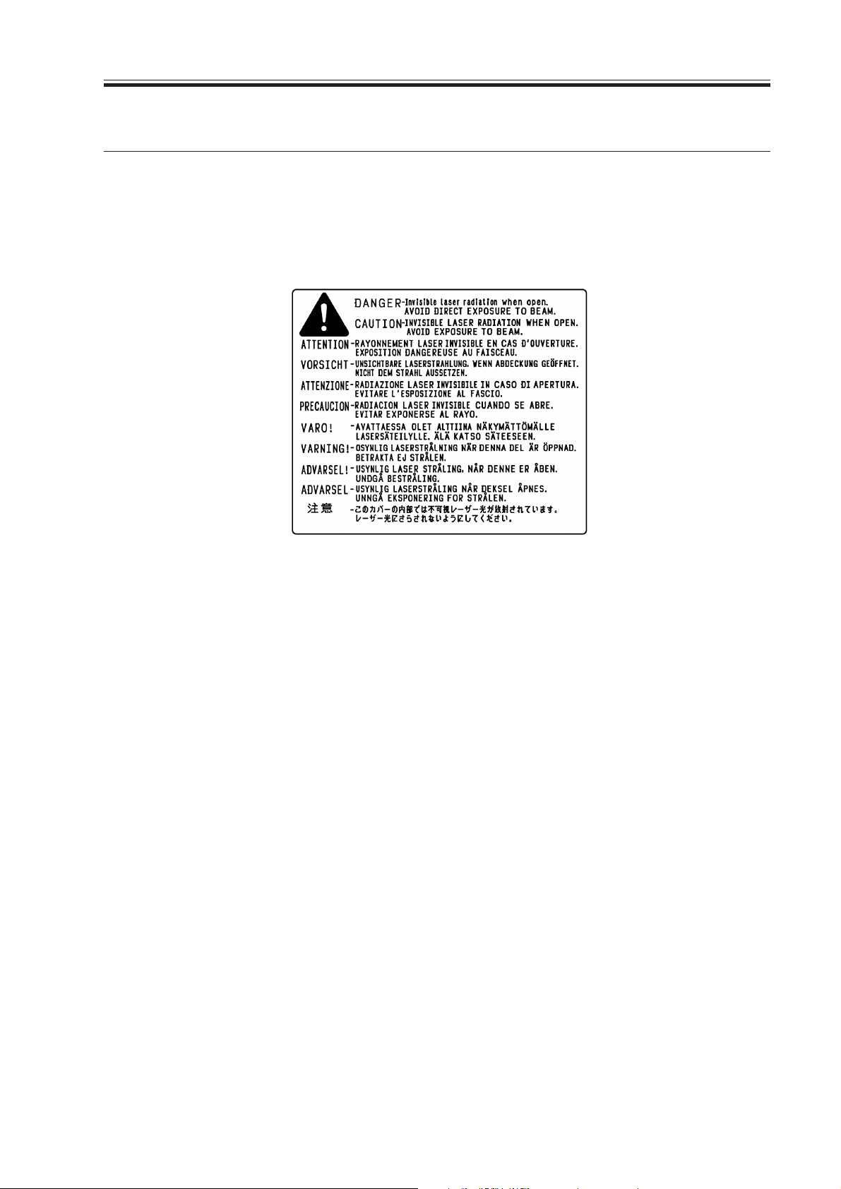
3.1 Laser Safety
The laser/scanner unit emits invisible laser beam. DO NOT disassemble the unit as the
laser beam can possibly damage your eyes. The unit cannot be adjusted in the field. The
following label is attached to the cover of the unit:
F01-301-01
3.2 Toner Safety
Toner is a harmless substance composed of plastics and a small amount of pigment.
If you get toner on your skin or clothes, remove as much as possible with dry tissue and
then wash it with cold water. If you wash in hot water, the toner gels and becomes hard to
remove. As toner easily decomposes vinyl material, do not let it come into contact with the
material.
3.3 Ozone Safety
An infinitesimal amount of ozone gas (O3) is generated during corona discharge from the
cleaning charging roller used in this printer. The ozone gas is emitted only when the printer
is operating.
The printer meets the ozone emission standard decided by the Underwriters Laboratories
Inc. (UL) when it is shipped from the factory.
3.4 Power Supply Safety
Note that even if the power switch is turned off, the current still flows to the primary side
of the power supply unit.
Unplug the power cord before disassembling and reassembling the printer.
COPYRIGHT
©
2003 CANON INC. 2000 2000 2000 2000 CANON LBP-2410 REV.0 FEB. 2003
1-5
CHAPTER 1 PRODUCT INFORMATION
4 PARTS OF THE PRINTER
4.1 External View
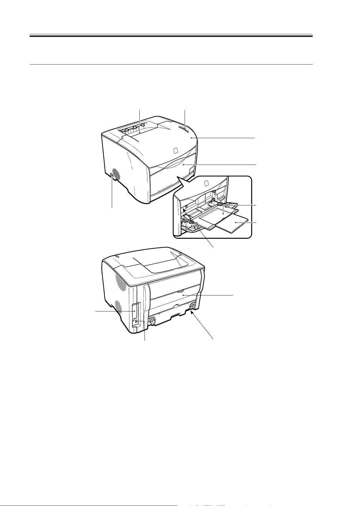
4.1.1 Printer
[1] [2]
[3]
[4]
[12]
[8]
[11]
F01-401-01
[5]
[6]
[7]
[9]
[10]
[1] Facedown tray
[2] Operation panel
[3] Top cover unit
[4] Front cover unit
[5] Multi-purpose tray
[6] Auxiliary tray
1-6
COPYRIGHT
©
[7] Test print switch
[8] Power switch
[9] Rear cover
[10]Power receptacle
[11]USB connector
[12]Expansion board slot
2003 CANON INC. 2000 2000 2000 2000 CANON LBP-2410 REV.0 FEB. 2003
CHAPTER 1 PRODUCT INFORMATION
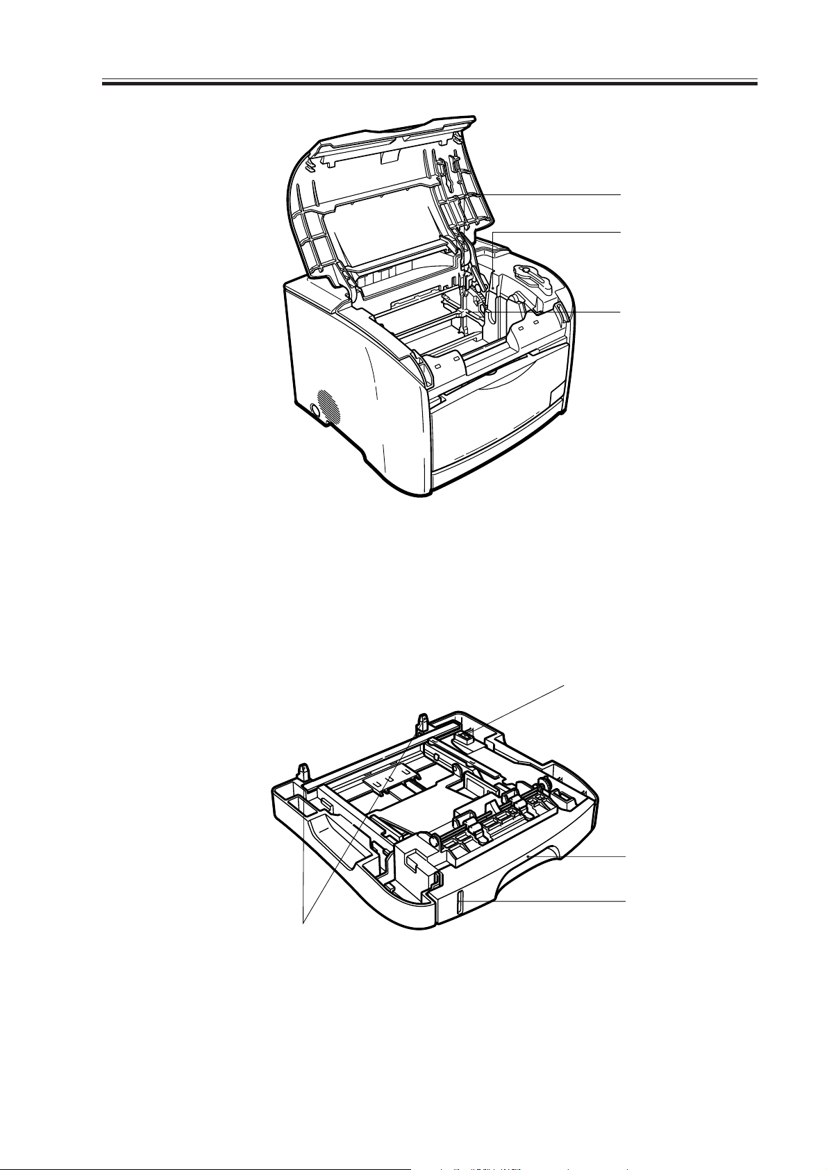
[13]
[14]
[15]
F01-401-02
[13]Toner cartridge slot
[14]Drum cartridge slot
4.1.2 Universal 250-sheet paper feeder
[4]
[15]Developing rotary
[1]
[2]
[3]
[1] Intermediate connector
[2] 250-sheet cassette
COPYRIGHT
©
2003 CANON INC. 2000 2000 2000 2000 CANON LBP-2410 REV.0 FEB. 2003
F01-401-03
[3] Paper level mark
[4] Positioning pins
1-7
CHAPTER 1 PRODUCT INFORMATION
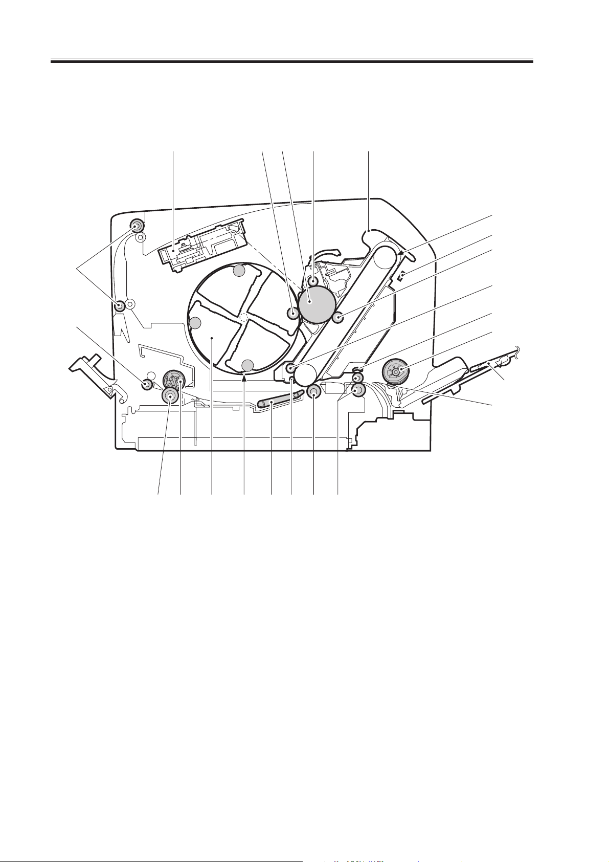
4.2 Cross Sectional View
4.2.1 Printer
[23]
[22]
[1]
[2] [3]
[4]
[5]
[6]
[7]
[8]
[9]
[10]
[11]
[12]
[13]
[20]
[21]
[1] Laser/scanner unit
[2] Developing cylinder
[3] Photosensitive drum
[4] Primary charging roller
[5] EP-87 drum cartridge
[6] ITB
[7] Density sensor
[8] Primary transfer roller
[9] ITB cleaning roller
[10]Registration shutter
[11]Pick-up roller
[12]Multi-purpose tray
[19]
[18]
F01-402-01
[16][17]
[15]
[14]
[13]Separation pad
[14]Registration roller unit
[15]Secondary transfer roller
[16]Auxiliary ITB cleaning roller
[17]Feed belt
[18]Developing rotary
[19]EP-87 Toner cartridge
[20]Fixing film unit
[21]Pressure roller
[22]Fixing delivery roller
[23]Facedown delivery roller
1-8
COPYRIGHT
©
2003 CANON INC. 2000 2000 2000 2000 CANON LBP-2410 REV.0 FEB. 2003

4.2.2 Universal 250-sheet paper feeder
F01-402-02
[1] Pick-up roller
[2] Feed roller
[3] Separation pad
CHAPTER 1 PRODUCT INFORMATION
[1]
[2]
[3]
COPYRIGHT
©
2003 CANON INC. 2000 2000 2000 2000 CANON LBP-2410 REV.0 FEB. 2003
1-9

CHAPTER 1 PRODUCT INFORMATION
5 INSTALLATION
5.1 Outline
This printer is packaged and shipped from the factory after careful adjustments and strict
inspections.
To ensure that it performs as intended, it is very important to install the printer properly.
The service engineer should have a complete knowledge of the printer, choose an appropriate location, install the printer according to the proper procedure, and conduct sufficient
checks of the printer.
5.2 Selecting a location
Place the printer in a location where the following conditions are met. The service engineer should inspect the customer's premises before installing the printer.
5.2.1 Power supply
Use the power supplies that satisfies the following conditions:
• Line voltage (AC): Within ± 10 % of rated voltage
• Power frequency: 50/60 Hz ± 2 Hz
5.2.2 Operating environment
Place the printer in a location where the following conditions are met:
• Level, flat surface
• Temperature, humidity within the following ranges:
Surrounding temperature:10 - 30 °C
Surrounding humidity: 20 - 80 %RH
• Cool, well-ventilated space
Avoid placing the printer in the following locations:
• Places exposed to direct sunlight
If unavoidable, hang heavy curtains to shut out direct sunlight.
• Near magnets or devices that emit magnetic field
• Subject to vibration
• Dusty places
• Near fire or water
1-10
COPYRIGHT
©
2003 CANON INC. 2000 2000 2000 2000 CANON LBP-2410 REV.0 FEB. 2003
CHAPTER 1 PRODUCT INFORMATION
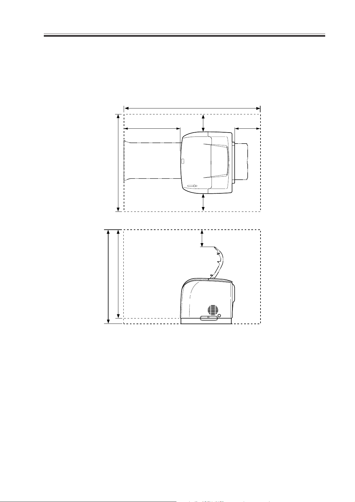
5.2.3 Space
Place the printer at a suitable distance from the walls, leaving enough room to operate it.
(See F01-502-01.) When placing the printer on a desk, be sure that it is large enough to accommodate the printer’s feet (rubber pads) and strong enough to stand printer's weight.
1175
758
682707
516
208
100100
100
COPYRIGHT
©
F01-502-01
2003 CANON INC. 2000 2000 2000 2000 CANON LBP-2410 REV.0 FEB. 2003
1-11
CHAPTER 1 PRODUCT INFORMATION
5.3 Unpacking and Installation
Condensation will form on metal surfaces in the printer when brought from a cold area to
a warm area. This can cause various troubles including print defects. In such a case, leave
it in the carton at room temperature for at least an hour before unpacking so that it is acclimatized to room temperature.
When installing optional units, be sure that the printer is turned off.
5.3.1 Printer
1) Remove the printer from the packaging.
2) Take out the accessories. Confirm that the power cord, four EP-87 toner cartridges, and
EP-87 drum cartridge are included.
3) Remove the plastic bag from the printer and peel off the tape securing components.
Confirm that none of the covers were scratched or deformed during shipment.
4) Open the top cover, peel off the tape, and remove the packaging. Close the top cover.
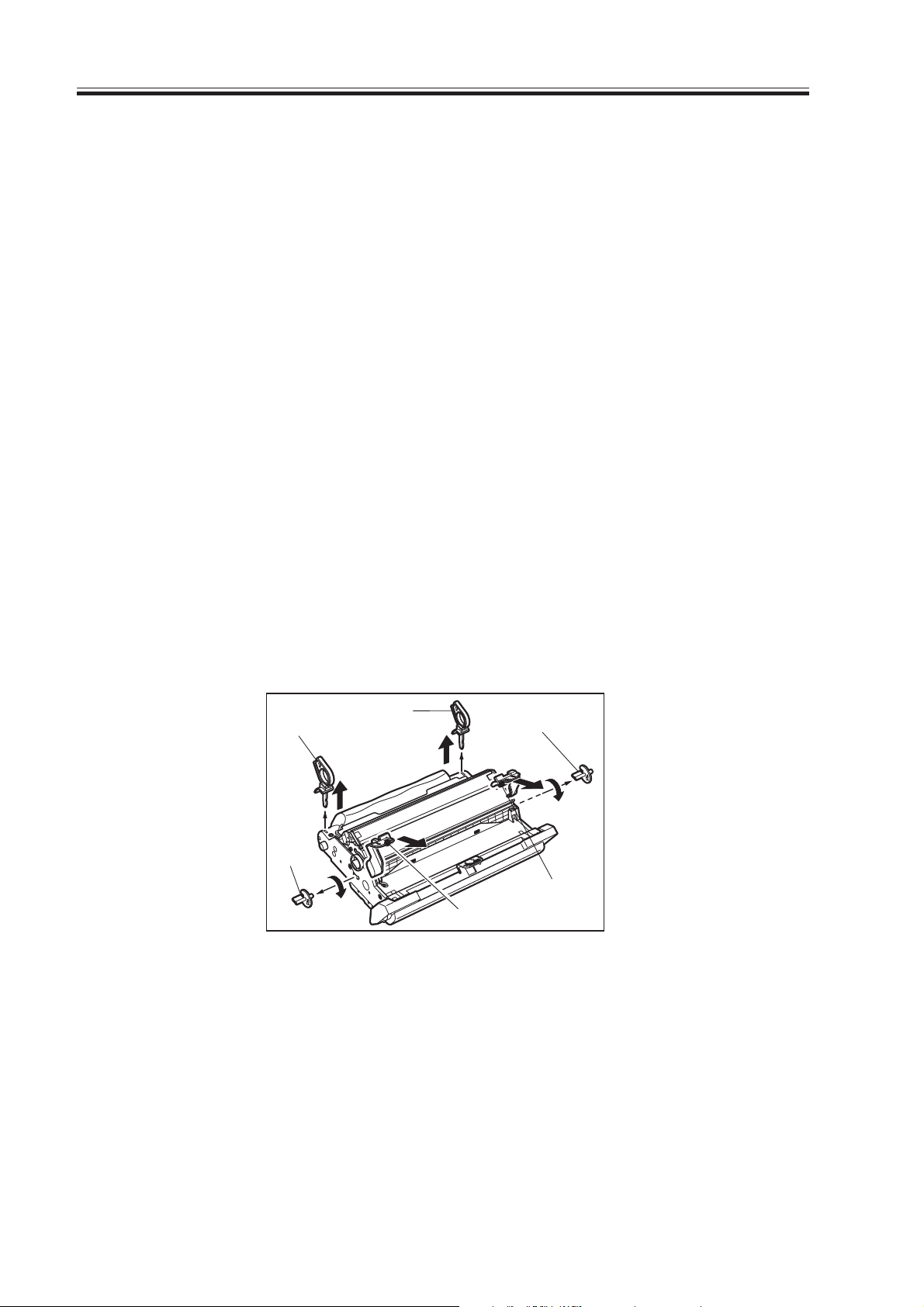
5.3.2 EP-87 Drum Cartridge
1) Lift up both ends of the top cover and open it.
2) Remove the EP-87 drum cartridge from the plastic bag.
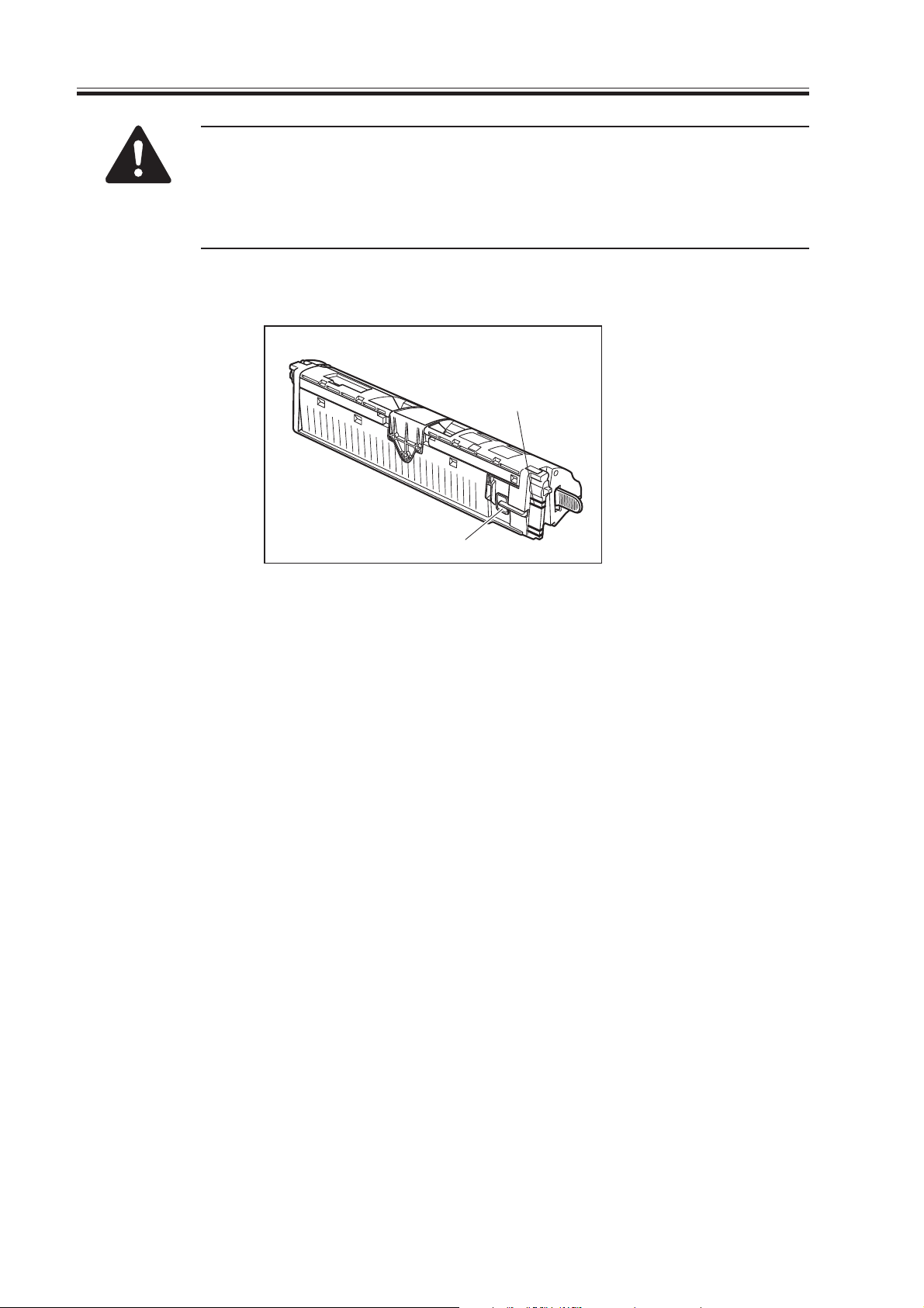
3) Pull up the stoppers 1 and 2 (see the figure below).
4) Turn the stoppers 3 and 4 90 degrees in the direction of the arrow and then pull them out
to the sides (see the figure below).
5) Pull up the stoppers 5 and 6 (see the figure below).
[1] Stopper 1
[2] Stopper 2
[3] Stopper 3
[1]
[3]
[2]
[4]
[6]
[5]
F01-503-01
[4] Stopper 4
[5] Stopper 5
[6] Stopper 6
1-12
COPYRIGHT
©
2003 CANON INC. 2000 2000 2000 2000 CANON LBP-2410 REV.0 FEB. 2003

6) Remove the protective cover.
[1] Protective cover
CHAPTER 1 PRODUCT INFORMATION
[1]
F01-503-02
7) Hold the EP-87 drum cartridge with both hands as shown below and insert it into the
printer firmly.
F01-503-03
8) Close the top cover firmly.
COPYRIGHT
©
2003 CANON INC. 2000 2000 2000 2000 CANON LBP-2410 REV.0 FEB. 2003
1-13
CHAPTER 1 PRODUCT INFORMATION
5.3.3 EP-87 Toner cartridge
Toner replacement mode
This printer utilizes toner replacement mode to make EP-87 toner cartridge
replacement smooth.
This function detects toner cartridge presence when the power is turned on
or the top cover is closed. If not all of the cartridges are installed, the developing rotary automatically rotates that the compartment of a missing
toner cartridge comes to the installation slot. If two or more cartridges are
not installed, close the top cover after each installation so that the rotary
will rotate for the next missing cartridge. Detection and installation of the
toner cartridges are conducted in order of Y, M, C, and Bk.
A message will be indicated to prompt replacement when the toner cartridge reaches the end of its life. Hold down the Replace Toner key found in
the machine's upper left for 1 sec or more to move the cartridge to its position of replacement.
1) Insert the power cord and grounding cord to the printer and outlet. Be sure to use the
supplied power cord.
2) Turn on the printer.
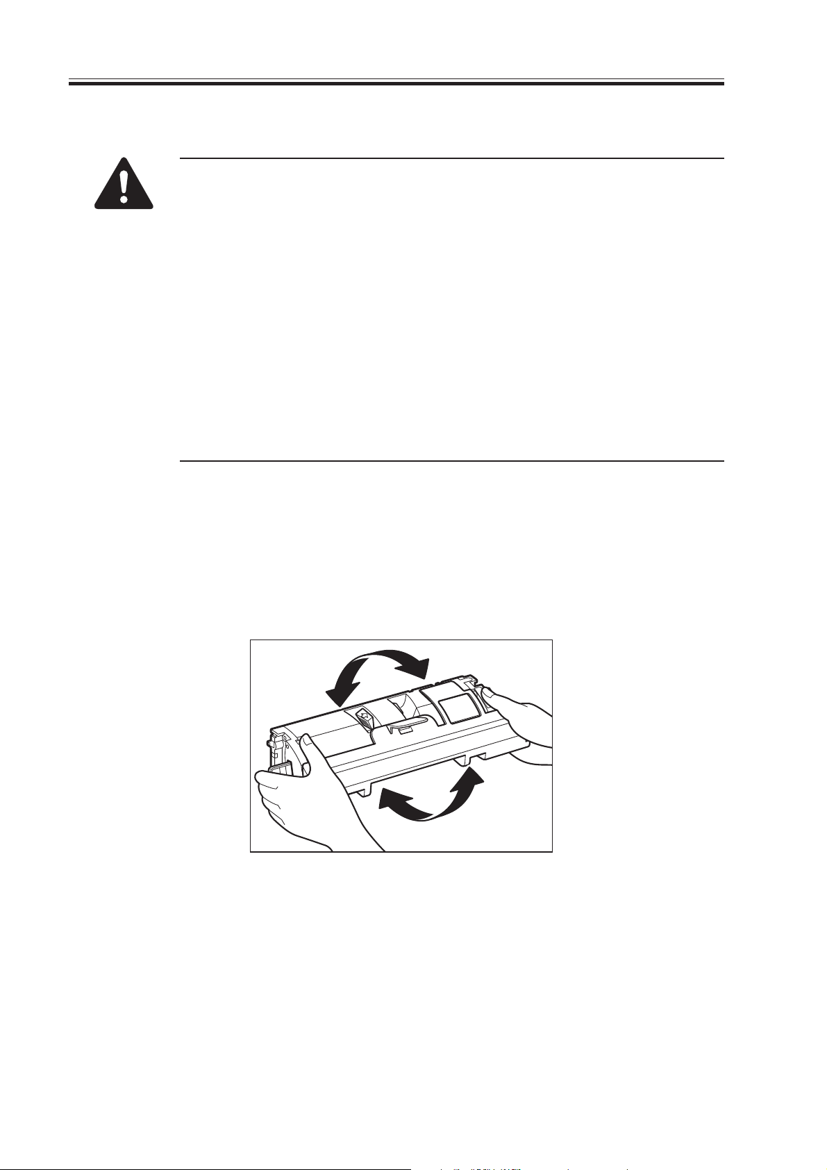
3) Remove the toner cartridge out of its protective bag.
4) Hold the cartridge as shown below and slowly rock it up and down five or six times to
distribute toner evenly.
F01-503-04
1-14
COPYRIGHT
©
2003 CANON INC. 2000 2000 2000 2000 CANON LBP-2410 REV.0 FEB. 2003
CHAPTER 1 PRODUCT INFORMATION
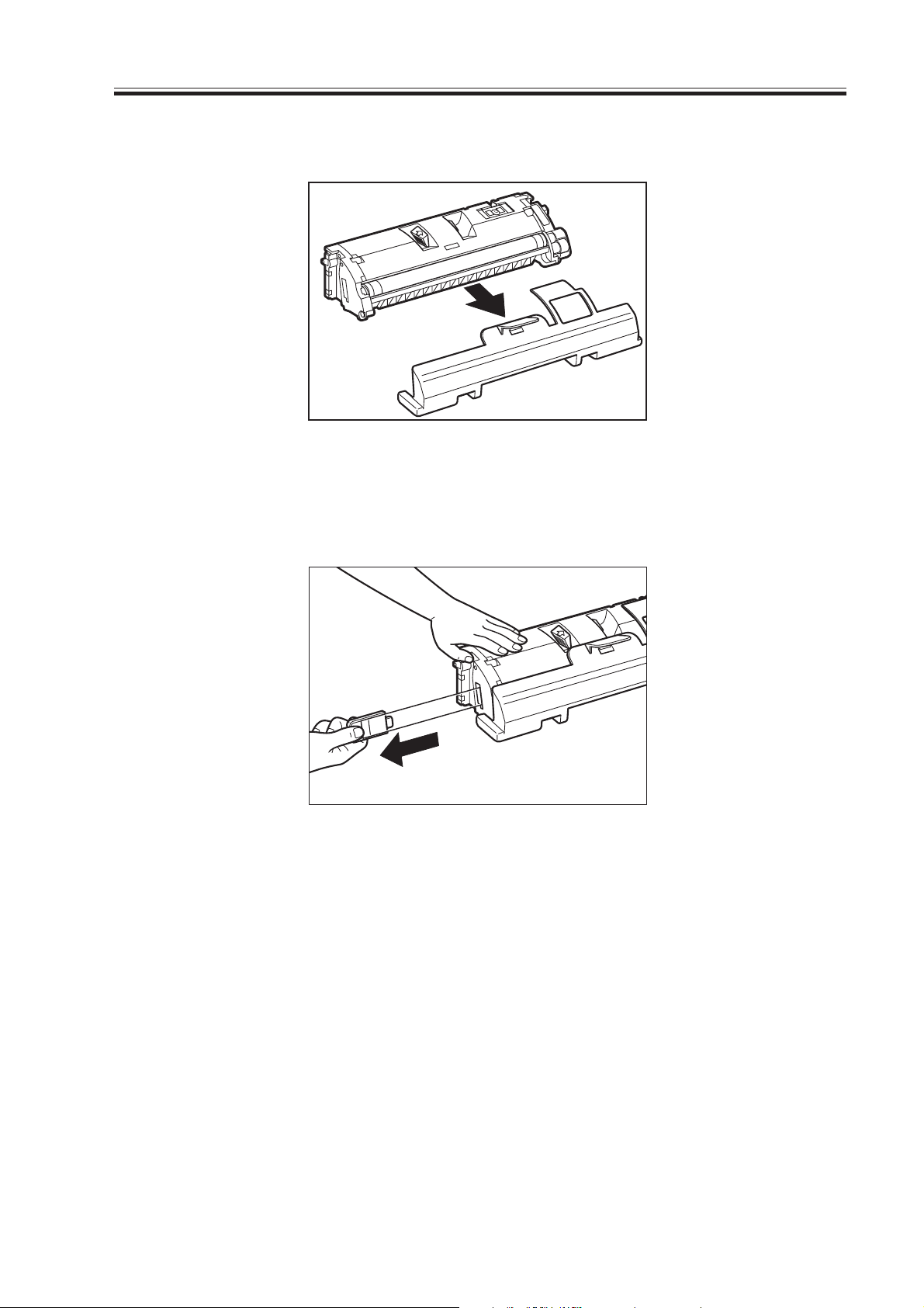
5) Remove the protective cover.
F01-503-05
6) Place the cartridge on a level surface and hold down the top of the cartridge with one
hand and pull out the tab gently with the other hand to remove the sealing tape.
F01-503-06
7) Open the top cover.
At this point, the toner cartridge Y compartment is at the installation slot as performed in
toner replacement mode (see note).
COPYRIGHT
©
2003 CANON INC. 2000 2000 2000 2000 CANON LBP-2410 REV.0 FEB. 2003
1-15

CHAPTER 1 PRODUCT INFORMATION
8) Check the seal and prepare the cartridge (Y) with the same color as the color seal.
Color seal
F01-503-07
9) Grasp the finger holding on the cartridge. Align the arrow mark on the toner cartridge
with the color mark on the printer and insert the cartridge into the printer.
F01-503-08
10) Close the top cover.
11) The printer will rotate the developing rotary so that the next compartment comes to the
replacement position for the next cartridge (M).
12) Repeat steps 3) to 12) in this procedure to install the remaining cartridges.
13) After inserting all the toner cartridges in the machine, close the upper cover and hold
down the Replace Toner key for 1 sec or more.
1-16
COPYRIGHT
©
2003 CANON INC. 2000 2000 2000 2000 CANON LBP-2410 REV.0 FEB. 2003

CHAPTER 1 PRODUCT INFORMATION
5.3.4 Paper feeder
1) Remove the paper feeder from the packaging.
2) Remove the plastic bag from the paper feeder and peel off the tapes securing the components. Confirm that none of the covers were scratched or deformed during shipment.
3) Take out the cassette from the paper feeder and remove the packaging and plastic materials (stoppers) holding the lifting plate.
4) Place the paper feeder on the level surface.
5) Lift up the printer. Align the positioning pins of the paper feeder and the positioning
holes of the printer. Install the printer on the top of the paper feeder.
When installing the paper feeder, be sure to turn off the printer and unplug
the power cord.
5.3.5 Confirming the performance
1) Open the multi-purpose tray.
2) Place paper on the tray.
3) Set the paper size guide at a specified position appropriate to the paper size.
4) Plug the “provided” power cord into the printer and outlet. Turn of the printer.
5) When the printer enters a standby status, press the test print switch (see F01-401-01.)
Check the output image for image defects.
6) Clean around the printer to allow the use of the printer at any time.
5.4 Notes for Storing and Handling the EP-87 Drum Cartridge
and EP-87 Toner Cartridge
The drum cartridge and toner cartridge scan be affected by the environment and change
over time whether they are still sealed in the box or installed in the printer, regardless of the
number of prints. Since the pace at which it changes depends on installation and storage environments, be very careful in storing and handling them.
5.4.1 Storing the sealed cartridges
When storing in a warehouse or workshop (service depot), store in a specified installation
environment. Note the following also:
1) Avoid areas exposed to sunlight.
2) Avoid areas that are subject to vibration.
3) Do not bump or drop it.
COPYRIGHT
©
2003 CANON INC. 2000 2000 2000 2000 CANON LBP-2410 REV.0 FEB. 2003
1-17

CHAPTER 1 PRODUCT INFORMATION
5.4.2 Storing the unsealed cartridges
A drum cartridge contains a photosensitive drum coated with an organic photoconductor
(OPC) that deteriorates when exposed to strong light. A toner cartridge contains toner. Advise the customer correct storing and handling of the cartridges.
a. Storage precautions
1) Store the cartridge always in its protection bag.
2) Avoid areas exposed to sunlight or near windows. Do not leave a cartridge in a car for a
long time, as the inside of the car can get extremely hot.
3) Avoid areas that get extremely hot and humid or extremely cold and dry. Also, avoid
areas where the temperature can change suddenly.
4) Avoid a salty air environment or areas exposed to corrosive gases, such as aerosols.
5) Store the cartridge in the temperature range 0 to 35 °C.
6) Keep cartridges away from computer CRT displays, disk drives, and floppy disks.
7) Keep the cartridge out of reach of children.
b. Handling precautions
1) Before installing a new toner cartridge in the printer, distribute the toner evenly as
shown in F01-503-04. Rocking it any other way may result in toner leaking from the
developing cylinder.
After installing a new cartridge, print three to five test patterns to check for toner leakage
to avoid image defects.
2) Before transporting the printer, remove all the cartridges.
Place the removed cartridges in their protection bag to avoid exposing them to light.
3) Do not expose all the cartridges to sunlight or strong light, since they are sensitive to
light. Otherwise, it may result in image defects.
4) Do not touch or scratch the surface of the photosensitive drum.
5) Do not stand all the cartridges on end or turn them upside down. Labeled side of the
cartridges should be facing up always.
6) Do not attempt to disassemble any cartridges.
7) Do not touch the waste toner detection window on the drum cartridge.
1-18
Waste toner
detection window
F01-504-01
COPYRIGHT
©
2003 CANON INC. 2000 2000 2000 2000 CANON LBP-2410 REV.0 FEB. 2003

CHAPTER 1 PRODUCT INFORMATION
8) Do not touch or open the protective shutter on the drum cartridge.
Protective shutter
Photosensitive drum
F01-504-02
9) Do not touch or scratch the surface of the ITB of the drum cartridge.
Imaging transfer belt
F01-504-03
10) Do not touch or scratch the surface of the electrical contact of the drum cartridge.
Electr ical
contacts
F01-504-04
COPYRIGHT
©
2003 CANON INC. 2000 2000 2000 2000 CANON LBP-2410 REV.0 FEB. 2003
1-19
CHAPTER 1 PRODUCT INFORMATION
The photosensitive drum is protected by the protective shutter as blank
spots or black lines may appear on the prints if the drum is exposed to
strong light. Therefore, avoid opening the shutter. (The protective shutter
opens automatically when the EP-87 drum cartridge is installed in the
printer.)
11) Do not touch the light guide and electrical contact of the toner cartridge.
Electrical contact
light guide
F01-504-05
1-20
COPYRIGHT
©
2003 CANON INC. 2000 2000 2000 2000 CANON LBP-2410 REV.0 FEB. 2003
 Loading...