


Canon J1 Service Manual
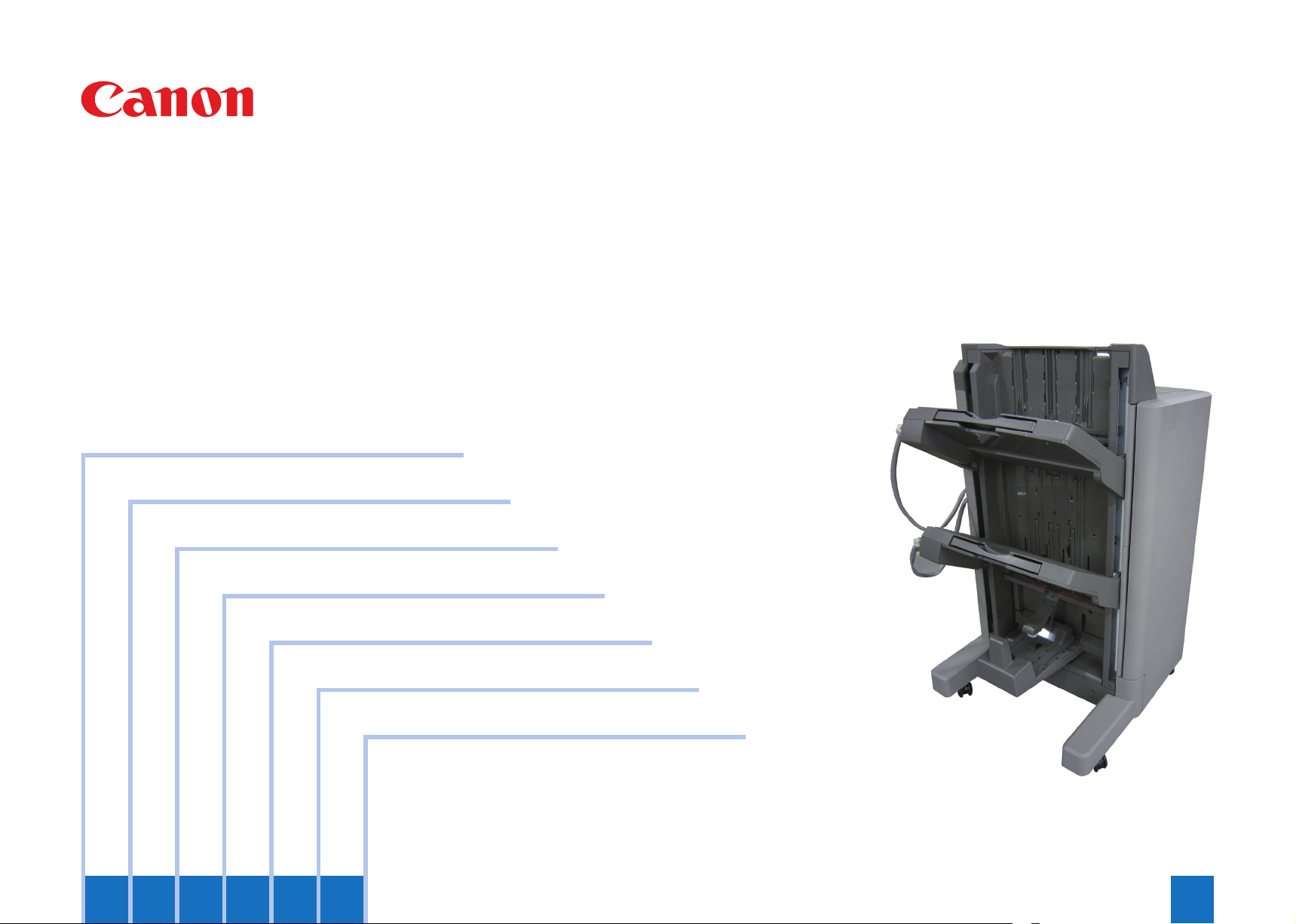
Staple Finisher-J1 / Booklet Finisher-J1
Product Outline
Technology
Periodic Servicing
Parts Replacement and Cleaning Procedure
Adjustment
Installation
Appendix
Service Manual Rev0
654321

0-2
Application
This manual has been issued by Canon Inc. for qualied persons to learn technical theory,
installation, maintenance, and repair of products. This manual covers all localities where
the products are sold. For this reason, there may be information in this manual that does
not apply to your locality.
Corrections
This manual may contain technical inaccuracies or typographical errors due to
improvements or changes in products. When changes occur in applicable products or in the
contents of this manual, Canon will release technical information as the need arises. In the
event of major changes in the contents of this manual over a long or short period, Canon
will issue a new edition of this manual.
The following paragraph does not apply to any countries where such provisions are
inconsistent with local law.
Trademarks
The product names and company names used in this manual are the registered trademarks
of the individual companies.
Copyright
This manual is copyrighted with all rights reserved. Under the copyright laws, this manual
may not be copied, reproduced or translated into another language, in whole or in part,
without the consent of Canon Inc.
© CANON INC. 2012
Caution
Use of this manual should be strictly supervised to avoid disclosure of condential
information.
0-2
0
0-3
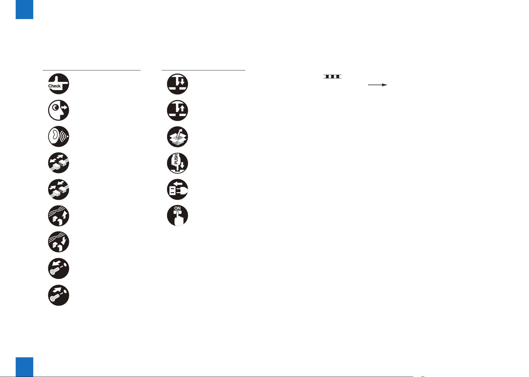
Explanation of Symbols
The following symbols are used throughout this Service Manual.
Symbols Explanation Symbols Explanation
Check. Remove the claw.
Check visually. Insert the claw.
Check the noise. Use the bundled part.
Disconnect the connector. Push the part.
Connect the connector. Plug the power cable.
Remove the cable/wire
from the cable guide or wire
saddle.
Turn on the power.
The following rules apply throughout this Service Manual:
1. Each chapter contains sections explaining the purpose of specic functions and the
relationship between electrical and mechanical systems with reference to the timing of
operation.
In the diagrams, represents the path of mechanical drive; where a signal name
accompanies the symbol, the arrow indicates the direction of the electric signal.
The expression "turn on the power" means ipping on the power switch, closing the front
door, and closing the delivery unit door, which results in supplying the machine with power.
2. In the digital circuits, '1' is used to indicate that the voltage level of a given signal is "High",
while '0' is used to indicate "Low". (The voltage value, however, differs from circuit to
circuit.) In addition, the asterisk (*) as in "DRMD*" indicates that the DRMD signal goes on
when '0'.
In practically all cases, the internal mechanisms of a microprocessor cannot be checked
in the eld. Therefore, the operations of the microprocessors used in the machines are not
discussed: they are explained in terms of from sensors to the input of the DC controller
PCB and from the output of the DC controller PCB to the loads.
The descriptions in this Service Manual are subject to change without notice for product
improvement or other purposes, and major changes will be communicated in the form of
Service Information bulletins.
All service persons are expected to have a good understanding of the contents of this Service
Manual and all relevant Service Information bulletins and be able to identify and isolate
faults in the machine.
0
Set the cable/wire to the
cable guide or wire saddle.
Remove the screw.
Tighten the
0-3

Blank Page

Contents
0
Safety Precautions
Notes Before it Works Serving ---------------------------------------------0-9
Points to Note at Cleaning --------------------------------------------------0-9
1
Product Outline
Features -------------------------------------------------------------------------1-2
Specications ------------------------------------------------------------------1-3
Saddle Stitcher Unit --------------------------------------------------------------- 1-4
Names of Parts ----------------------------------------------------------------1-6
External View ----------------------------------------------------------------------- 1-6
Finisher (Staple Finisher) ----------------------------------------------------------------- 1-6
Saddle Finisher (Booklet Finisher) ----------------------------------------------------- 1-6
Cross Section ----------------------------------------------------------------------- 1-7
Finisher Unit ---------------------------------------------------------------------------------- 1-7
Saddle Unit ----------------------------------------------------------------------------------- 1-7
Optional Construction --------------------------------------------------------1-8
2
Technology
Basic Constitution -------------------------------------------------------------2-2
Component Conguration ------------------------------------------------------- 2-2
Finisher (Staple Finisher) ----------------------------------------------------------------- 2-2
Saddle Finisher (Booklet Finisher) ----------------------------------------------------- 2-2
Overview of the Electrical Circuitry -------------------------------------------- 2-3
Overview of the Electrical Circuitry (Saddle Stitcher Unit)--------------- 2-3
Controls --------------------------------------------------------------------------2-4
Feeding Unit --------------------------------------------------------------------2-5
Overview ----------------------------------------------------------------------------- 2-5
Staple Finisher ------------------------------------------------------------------------------ 2-5
Booklet Finisher ----------------------------------------------------------------------------- 2-5
Construction of the Control System ------------------------------------------ 2-6
Staple Finisher ------------------------------------------------------------------------------ 2-6
0-5
Booklet Finisher ----------------------------------------------------------------------------- 2-8
Paper Delivery Path --------------------------------------------------------------- 2-9
Straight Ejection ----------------------------------------------------------------------------- 2-9
Processing Tray Path ---------------------------------------------------------------------2-10
Buffer/Processing Tray Path ------------------------------------------------------------2-10
Paper Delivery Path (Saddle Stitcher Unit) -----------------------------------------2-11
Stack Tray Unit -------------------------------------------------------------- 2-12
Tray Operation ---------------------------------------------------------------------2-12
Shutter Operation -----------------------------------------------------------------2-13
Processing Tray Unit ------------------------------------------------------- 2-14
Outline ------------------------------------------------------------------------------- 2-14
Basic Operation -------------------------------------------------------------------2-14
Processing Tray Paper Stacking Operation -----------------------------------------2-14
Stack Delivery Operation ----------------------------------------------------------------2-14
Stack Job Offset ---------------------------------------------------------------------------2-15
Staple Operation ---------------------------------------------------------------------------2-16
Swing Height Detection Control --------------------------------------------------------2-17
Saddle Stitcher Unit -------------------------------------------------------- 2-18
Basic Operation (Saddle Stitcher Unit) --------------------------------------2-18
Receiving Sheets --------------------------------------------------------------------------2-18
Aligning the Sheets------------------------------------------------------------------------2-18
Stitching --------------------------------------------------------------------------------------2-19
Feeding the Stack -------------------------------------------------------------------------2-19
Folding/Delivering the Stack ------------------------------------------------------------2-20
Controlling the Inlet Flappers --------------------------------------------------2-20
Overview -------------------------------------------------------------------------------------2-20
A3/A3/ 305mm x 457mm (12 x 18)/ 279mm x 432mm (11 x 17) Paper Path (3
sheets) ----------------------------------------------------------------------------------------2-21
B4/LGL Paper Path (3 sheets) ---------------------------------------------------------2-21
A4R/LTRR Paper Path (3 sheets) -----------------------------------------------------2-22
Controlling the Movement of Sheets -----------------------------------------2-22
Controlling the Aligning the Sheets -------------------------------------------2-23
Controlling the Phase of the Crescent Roller ------------------------------ 2-25
Overview of Folding Operation ------------------------------------------------ 2-26
Overview -------------------------------------------------------------------------------------2-26
Controlling the Movement of Stacks --------------------------------------------------2-26
Folding a Stack -----------------------------------------------------------------------------2-27
Double Folding a Stack ------------------------------------------------------------------2-28
0-5

0
0-6
Staple Operation ------------------------------------------------------------ 2-30
Overview ---------------------------------------------------------------------------- 2-30
Stapler Unit -------------------------------------------------------------------------2-30
Stapler --------------------------------------------------------------------------------------- 2-30
Shifting the Stapler Unit ------------------------------------------------------------------2-31
Stapling Operation-------------------------------------------------------------------------2-33
Stitcher Unit ------------------------------------------------------------------------2-36
Stitcher ---------------------------------------------------------------------------------------2-36
Stitching Operation ------------------------------------------------------------------------2-36
Detecting Jams -------------------------------------------------------------- 2-37
Detecting Jams (Finisher Unit) ------------------------------------------------2-37
Detecting Jams (Saddle Stitcher Unit) ---------------------------------------2-38
Power Supply ---------------------------------------------------------------- 2-39
Power Supply Route (Finisher Unit) ------------------------------------------2-39
Power Supply Route ----------------------------------------------------------------------2-39
Protection Function------------------------------------------------------------------------2-39
Power Supply Route (Saddle Stitcher Unit) --------------------------------2-39
Power Supply Route ----------------------------------------------------------------------2-39
Protection Function------------------------------------------------------------------------2-39
Work of Service -------------------------------------------------------------- 2-40
User Maintenance ----------------------------------------------------------------2-40
Maintenance and Inspection --------------------------------------------------- 2-40
Periodical Servicing -----------------------------------------------------------------------2-40
Periodically Replaced Parts -------------------------------------------------------------2-40
Durables -------------------------------------------------------------------------------------2-40
Measures at Time of Parts Replacement -----------------------------------2-40
Upgrading ---------------------------------------------------------------------------2-40
3
Periodic Servicing
List of Work for Scheduled Servicing ------------------------------------3-2
4
Parts Replacement and Cleaning Procedure
List of Parts ---------------------------------------------------------------------4-2
External Covers -------------------------------------------------------------------- 4-2
Staple Finisher ------------------------------------------------------------------------------ 4-2
Saddle Finisher (Booklet Finisher) ----------------------------------------------------- 4-3
Main Units --------------------------------------------------------------------------- 4-4
List of Consumable Parts and Cleaning Parts ------------------------------ 4-5
List of Sensors ---------------------------------------------------------------------- 4-6
Staple Finisher Unit ------------------------------------------------------------------------ 4-6
Saddle Finisher Unit ----------------------------------------------------------------------- 4-7
List of Switchs ---------------------------------------------------------------------- 4-8
Staple Finisher Unit ------------------------------------------------------------------------ 4-8
Saddle Finisher Unit ----------------------------------------------------------------------- 4-8
List of Solenoid --------------------------------------------------------------------- 4-9
Staple Finisher Unit ------------------------------------------------------------------------ 4-9
Saddle Finisher Unit ----------------------------------------------------------------------- 4-9
List of PCBs ------------------------------------------------------------------------ 4-10
Staple Finisher Unit -----------------------------------------------------------------------4-10
Saddle Finisher Unit ----------------------------------------------------------------------4-10
List of Motors ----------------------------------------------------------------------- 4-11
Staple Finisher Unit -----------------------------------------------------------------------4-11
Saddle Finisher Unit ----------------------------------------------------------------------4-12
List of Clutches -------------------------------------------------------------------- 4-13
Other ---------------------------------------------------------------------------------4-13
External Covers ------------------------------------------------------------- 4-14
Removing the Front Cover -----------------------------------------------------4-14
Removing the Rear Cover ------------------------------------------------------4-14
Removing the Left Upper Cover ----------------------------------------------4-15
Removing the Upper Cover ----------------------------------------------------4-15
Removing the Grate-shaped Upper Guide --------------------------------- 4-16
Removing the Grate-shaped Lower Guide --------------------------------- 4-16
Removing the Front Inside Upper Cover ------------------------------------4-17
Removing the Front Inside Lower Cover (Staple Finisher) -------------4-17
Removing the Front Inside Lower Cover (Saddle Finisher) ------------ 4-18
Removing the PCB Cover (Saddle Finisher) ------------------------------4-18
Main Units --------------------------------------------------------------------- 4-19
Removing the Swing Unit -------------------------------------------------------4-19
Removing the Processing Tray ------------------------------------------------4-21
Removing the Tray 1 -------------------------------------------------------------4-23
Removing the Tray 2 -------------------------------------------------------------4-24
Removing the Return Roller Unit ---------------------------------------------4-25
Removing the Saddle Unit ------------------------------------------------------4-26
Removing the Stitcher Mount Unit --------------------------------------------4-27
0
0-6

0
0-7
Removing the Positioning Plate Unit -----------------------------------------4-28
Removing the Saddle Delivery Tray Unit -----------------------------------4-28
Removing the Upper Delivery Guide -----------------------------------------4-29
Removing the Inlet Feed Unit --------------------------------------------------4-29
Consumable Parts and Cleaning Points ------------------------------ 4-31
Removing the Stapler ------------------------------------------------------------4-31
Removing the Buffer Roller -----------------------------------------------------4-32
Removing the Return Roller ----------------------------------------------------4-32
Removing the Swing Unit Static Charge Eliminator ----------------------4-33
Removing the Inlet Static Charge Eliminator ------------------------------4-34
Removing the Stitcher Unit -----------------------------------------------------4-35
PCB ----------------------------------------------------------------------------- 4-36
Removing the Finisher Controller PCB --------------------------------------4-36
Action on replacing the nisher controller PCB ---------------------------4-36
Removing the Saddle Stitcher Controller PCB ---------------------------- 4-36
Other Parts ------------------------------------------------------------------- 4-37
Removing the Paper Folding Roller ------------------------------------------4-37
Removing the No.1 Flappers and the No.2 Flappers -------------------- 4-39
5
Adjustment
Outline ---------------------------------------------------------------------------5-2
Main adjustment -------------------------------------------------------------------- 5-2
Adjustment item ----------------------------------------------------------------------------- 5-2
The setting of the function ---------------------------------------------------------------- 5-4
Basic Adjustment --------------------------------------------------------------5-7
Adjusting the Stacker Alignment Position ----------------------------------- 5-7
Adjusting the Staple Position --------------------------------------------------- 5-7
Adjusting the Height of the Swing Roller ------------------------------------ 5-8
Adjusting the Saddle Staple Position ----------------------------------------5-10
Adjusting the Saddle Alignment Position------------------------------------5-10
Adjusting the Processing Tray Return Amount --------------------------- 5-11
Adjusting the Processing Tray Return Speed. -----------------------------5-11
Initializing the RAM on Finisher -----------------------------------------------5-12
Adjusting the Bias Line of Saddle Delivery Paper -----------------------5-12
Overview -------------------------------------------------------------------------------------5-12
Adjustment ----------------------------------------------------------------------------------5-12
Function Setting Operation ---------------------------------------------------- 5-15
Adjustment at Time of Parts Replacement ---------------------------5-17
Action on replacing the nisher controller PCB ---------------------------5-17
Adjusting the Stitcher Unit ------------------------------------------------------ 5-18
6
Installation
How to Utilize This Installation Procedure ------------------------------6-2
When using the parts included in the package ----------------------------- 6-2
Symbols in the Illustration ------------------------------------------------------- 6-2
Product Name ------------------------------------------------------------------6-2
Checking Before Installation -----------------------------------------------6-3
Checking the Installation Site --------------------------------------------------- 6-3
Installing the Accessories -------------------------------------------------------- 6-3
Points to Note on installation ---------------------------------------------------- 6-4
Check Items when Turning OFF the Main Power-------------------------- 6-4
Checking the Contents ------------------------------------------------------6-5
Unpacking -----------------------------------------------------------------------6-6
Unpacking Procedure ------------------------------------------------------------- 6-6
Installation Procedure --------------------------------------------------------6-9
Preparing the Finisher for Installation ----------------------------------------- 6-9
Connecting to the Host Machine ----------------------------------------------6-10
Attaching the Labels etc --------------------------------------------------------- 6-11
Operation Check ------------------------------------------------------------ 6-13
Operation Check ------------------------------------------------------------------ 6-13
Adjusting the Tilt ------------------------------------------------------------- 6-14
Check the Tilt ----------------------------------------------------------------------6-14
Adjusting the Tilt -------------------------------------------------------------------6-15
Appendix
Service Tools ----------------------------------------------------------------------ii
Solvents and Oils --------------------------------------------------------------------- ii
Special Tools --------------------------------------------------------------------------- ii
General Circuit Diagram ------------------------------------------------------- iii
Staple Finisher-J1 --------------------------------------------------------------------iii
Booklet Finisher-J1 ------------------------------------------------------------------- v
0
0-7

Safety Precautions
Notes Before it Works Serving
■
Points to Note at Cleaning
■

Notes Before it Works Serving
CAUTION:
At servicing, be sure to turn off the power source according to the specied steps and
disconnect the power plug.
CAUTION:
Do not turn off the power switch when downloading is under way.
Turning off the main power switch while downloading is under way can disable the
machine.
Points to Note at Cleaning
CAUTION:
When performing cleaning using organic solvent such as alcohol, be sure to check that
the component of solvent is vaporized completely before assembling.
0-9
0-9
Product Outline
1
Features
■
Specications
■
Names of Parts
■
Optional Construction
■
Product Outline
1

1
Product Outline > Features
Features
Ofce environment improvement
• Operation sound reduction
Productivity improvement
• 51ppm→55ppm
Service improvement
• Downloading from host machine
• Adjustment of nisher in the service mode of host machine
1-2
Product Outline > Features
1
1-2
1
Product Outline > Specications
1-3
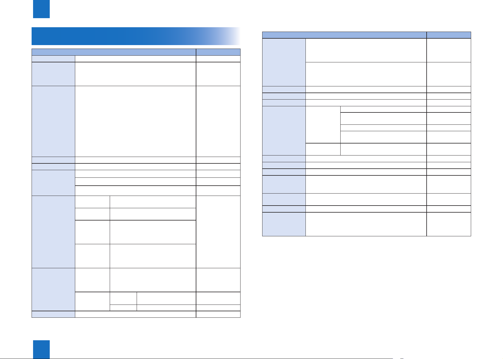
Specications
Item Specications Remarks
Stacking method
Stacking
orientation
Paper size
Paper weight
Bins
Modes
Stacking capacity
Mixed stacking
capacity
Tray 1 and 2: Independently move up and down
Face up, Face down Switching of the
stacking method is
done on the host
machine
A3, SRA3, A4, A4R, A5R, B4, B5, B5R, 305mm x 457mm
(12 x 18), 279mm x 432mm (11 x 17), LGL, LTR, LTRR,
STMT,STMTR, EXEC,8K,16K,others
52g/m2 to 256g/m2
2
Non sort: Tray 1 and 2
Sort: Tray 1 and 2
Staple: Tray 1 and 2
Tray 1: Non
staple sort
Tray 2: Non
staple sort
Tray 1: Staple
sort
Tray 2: Staple
sort
Mixed stacking
capacity Size
mixing
Large size: 96 mm high (650 sheets)
Small size: 188 mm high (1300 sheets)
Large size: 96 mm high (650 sheets)
Small size: 243 mm high (1700 sheets)
Large size: 96 mm high (650 sheets) or
30 sets
Small size: 188 mm high (1300 sheets)
or 30 sets
Large size: 96 mm high (650 sheets) or
30 sets
Small size: 243 mm high (1700 sheets)
or 30 sets
96 mm high Stacking capability
At the time of punch
connection
Feed direction:
139.7 to 483.0mm
Cross feed direction:
98.4 to 330.0mm
At the time of punch
non-connection
Feed direction: 148
to 483.0mm
Cross feed direction:
98.4 to 330.0mm
Equivalent of 81.4g/
m2 paper.
Alignment may not
be correct if 1700
or more small-size
sheets are stacked.
is not guaranteed for
mixed size stacking.
Item Specications Remarks
Stapling capacity
Staple supply
Staple detection
Manual stapling
Stapling size
Paper detection
Control panel
Display
Dimensions
Weight
Power supply
Maximum power
consumption
Small size:
Plain paper (52 to 81.4 g/m2): 50 sheets
Plain paper (81.4 to 105 g/m2):30 sheets
Thick paper (105 to 220 g/m2): 2 sheets
Large size:
Plain paper (52 to 81.4 g/m2): 30 sheets
Plain paper (81.4 to 105 g/m2):20 sheets
Thick paper (105 to 220 g/m2): 2 sheets
Special staple cartridge (5000 staples)
Provided (0 to 20 remaining staples)
Not provided
1-point stapling Front (30 deg.) : A4R, LGL, LTRR
Front (45 deg.) : A3, B4 ,A4, B5, 279mm
x 432mm(11 x 17), LTR, EXEC, 8K, 16K
Rear (30 deg.) : A4R, LGL, LTRR
Rear (45 deg.) : A3, B4 ,A4, B5, 279mm
x 432mm(11 x 17), LTR, EXEC, 8K, 16K
2-point stapling A3, A4, B4, B5, 279mm×432mm, 11×17,
LTR, LGL, EXEC, A4R, LTRR, 8K, 16K
Provided
Not provided
Not provided
W:559(677)×D:646×H:1097mm(Staple Finisher)
W:671(789)×D:646×H:1097mm(Booklet Finisher)
Staple Finisher: 46 kg
Booklet Finisher: 75 kg
From host machine (24VDC)
Staple Finisher:
10.5W or less during standby/ 100W or less operating
Booklet Finisher:
13.1W or less during standby/ 129W or less operating
Equivalent of 80g/
m2 paper.
The inside of () is
the size that the sub
tray was drawn.
• Paper Size Denition
Large size (feed length of 216 to 432 mm)
:A3, A4R, B4, B5R, 279mm x 432mm (11x 17), LGL,LTRR,8K
Small size (feed length of 216 mm or less):A4, A5R, B5, LTR, STMTR,18K,EXEC
T-1-1
Stapling
1
Stapling Small size 188mm high /30 sets
Large size 96 mm high /30 sets
By rotating cam
1-3
Product Outline > Specications
1
Product Outline > Specications > Saddle Stitcher Unit
1-4
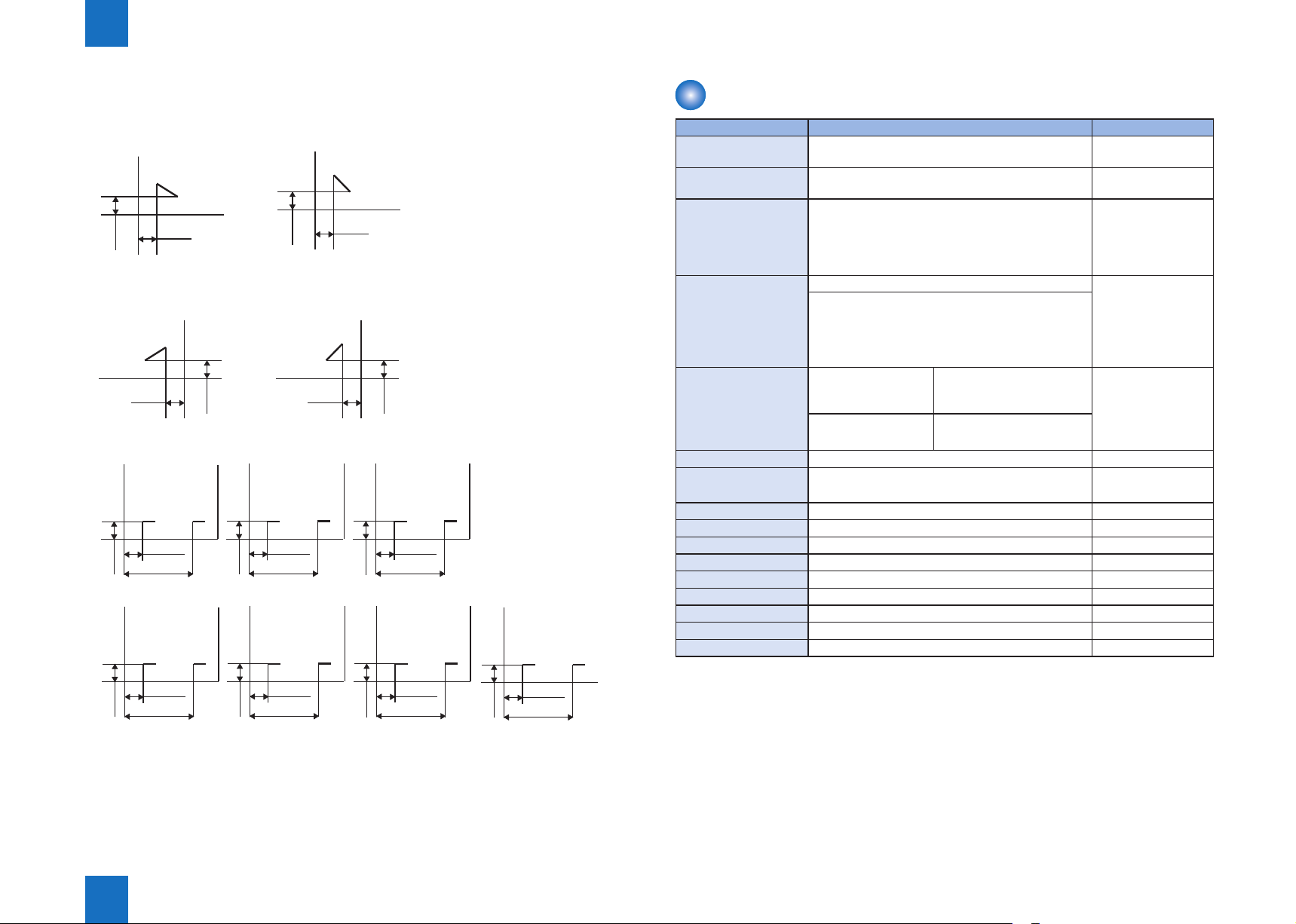
Stapling Positions
Front 1-point stapling (30deg.)
A4R, LGL and LTRR
5 -/+2 mm
5 -/+2 mm
Rear 1-point stapling (30deg.)
A4R, LGL and LTRR
5 -/+2 mm
5 -/+2 mm
2-point stapling
A3 and A4
83 -/+4 mm
203 -/+4 mm
5 -/+2 mm
A4R
39.5 -/+4 mm
159.5
-/+4 mm
5 -/+2 mm
279mm×432mm
(11×17)
74 -/+4 mm
194
5 -/+2 mm
LTRR and LGL
42.5 -/+4 mm
162.5
5 -/+2 mm
Front 1-point stapling (45deg.)
A3,A4,B4,B5,
279mm×432mm(11×17),LTR,EXEC,8K,16K
5 -/+2 mm
5 -/+2 mm
Rear 1-point stapling (45deg.)
A3,A4,B4,B5,
279mm×432mm(11×17),LTR,EXEC,8K,16K
5 -/+2 mm
5 -/+2 mm
B4 and B5
and LTR
63 -/+4 mm
183
-/+4
68.5 -/+4 mm
188.5
-/+4 mm
mm
EXEC
-/+4
-/+4 mm
mm
5 -/+2 mm
5 -/+2 mm
189.5
5 -/+2 mm
8K and 16K
69.5 -/+4 mm
-/+4 mm
F-1-1
Saddle Stitcher Unit
Item Specications Remarks
Stapling method
Paper size
Capacity
Paper weight
Stacking capacity
Stapling position
Staple
accommodation
Staple supply
Staples
Staple detection
Manual stapling
Folding method
Folding mode
Folding position
Position adjustment
Power supply
• Stacking capability is not guaranteed for mixed size stacking.
Vertically separated, round-clinch stapling at two
positions in the middle
A3, B4, A4R, 279mm x 432mm (11 x 17), LGL,
LTRR/ 305mm x 457mm (12 x 18)
52 to 81.4g/m2: 1 to 16 sheets
81.4 to 105g/m2: 1 to 10 sheets
105 to 150g/m2: 1 to 5 sheets
150 to 220g/m2: 1 to 4 sheets
209 to 220g/m2: 1 to 3 sheets
Plain paper: 52g/m2 to 220g/m2 Special paper,
Cover material: 52g/m2 to 256g/m2
52 to 81.4g/m2 1 to 5 sheets: 25 copies
6 to 10 sheets: 15 copies
11 to 16 sheets: 10 copies
81.4 to 105g/m2 1 to 5 sheets: 25 copies
6 to 10 sheets: 15 copies
2 points (center distribution; xed interval)
2000 staples
Special cartridge
Special staple (Staple-D3)
Provided
Not provided
Roller contact
Double folding
Paper center
Provided
From nisher unit (24VDC)
Including 1 cover
page.
postcards,
transparencies, or
elongation size can
not be
handled
Cover mode; up to 10
copies
T-1-2
Product Outline > Specications > Saddle Stitcher Unit
1
1-4
1
Product Outline > Specications > Saddle Stitcher Unit
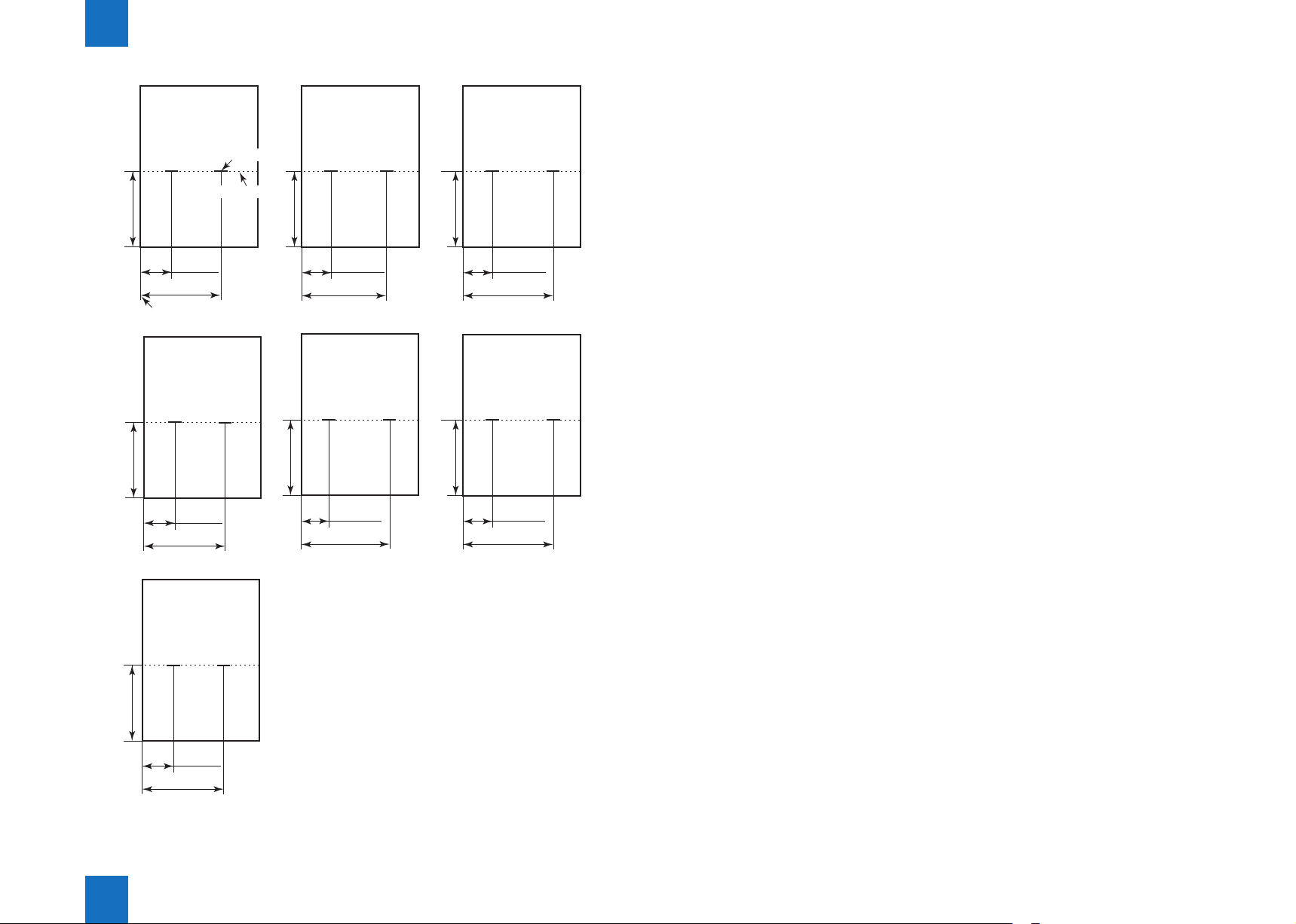
1-5
A3
Folding position
210 -/+1 mm
83
-/+2 mm
203 -/+2 mm
Stack front edge
279mm x 432mm
(11 x 17)
216 -/+1 mm
74
-/+2 mm
194 -/+2 mm
Staple position
B4
182 -/+1 mm
183 -/+2 mm
LGL
177.8 -/+1 mm
42 -/+2 mm
162 -/+2 mm
63 -/+2 mm
A4R
148.5 -/+1 mm
159.5
LTRR
139.7 -/+1 mm
42 -/+2 mm
162
39.5 -/+2 mm
-/+
2 mm
-/+
2 mm
305mm x 457mm
(12 x 18)
228.5 -/+1 mm
87.5
-/+2 mm
207.5 -/+2 mm
Product Outline > Specications > Saddle Stitcher Unit
1
F-1-2
1-5
1
Product Outline > Names of Parts > External View > Saddle Finisher (Booklet Finisher)
1-6
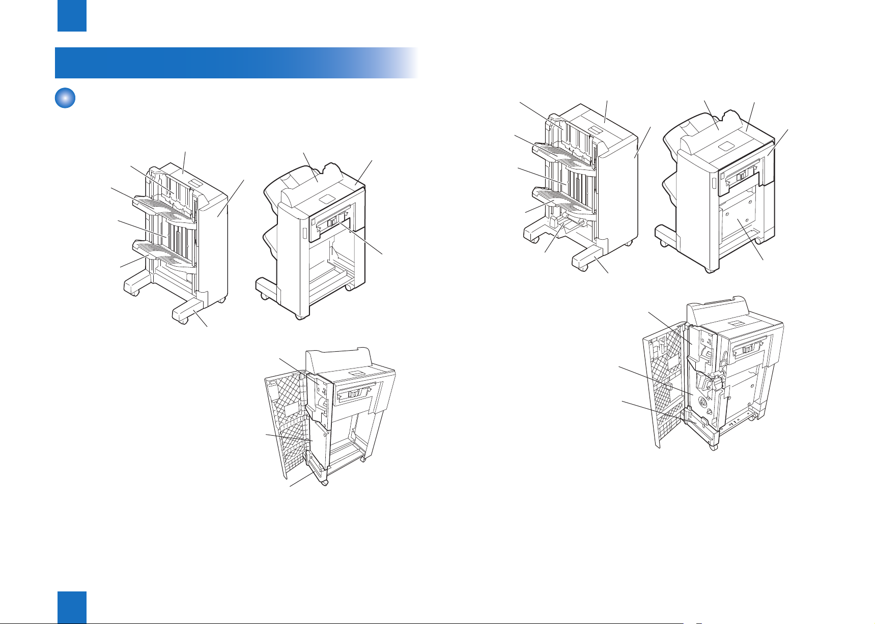
Names of Parts
External View
■Finisher (Staple Finisher)
Upper cover
Grate-shaped
upper guide
Tray 1
Grate-shaped
lower guide
Tray 2
Foot cover
Front cover
Front inside
upper cover
Left upper cover
Rear cover
latchunit
■Saddle Finisher (Booklet Finisher)
Grate-shaped
upper guide
Tray 1
Grate-shaped
lower guide
Tray 2
Saddle delivery tray
Upper cover
Front cover
Foot cover
Front inside
upper cover
Front inside
lower cover
Left upper cover
Rear cover
latchunit
PCB cover
Front inside
lower cover
Front foot
cover right
Product Outline > Names of Parts > External View > Saddle Finisher (Booklet Finisher)
1
Front foot
cover right
F-1-4
F-1-3
1-6
1
Product Outline > Names of Parts > Cross Section > Saddle Unit
1-7
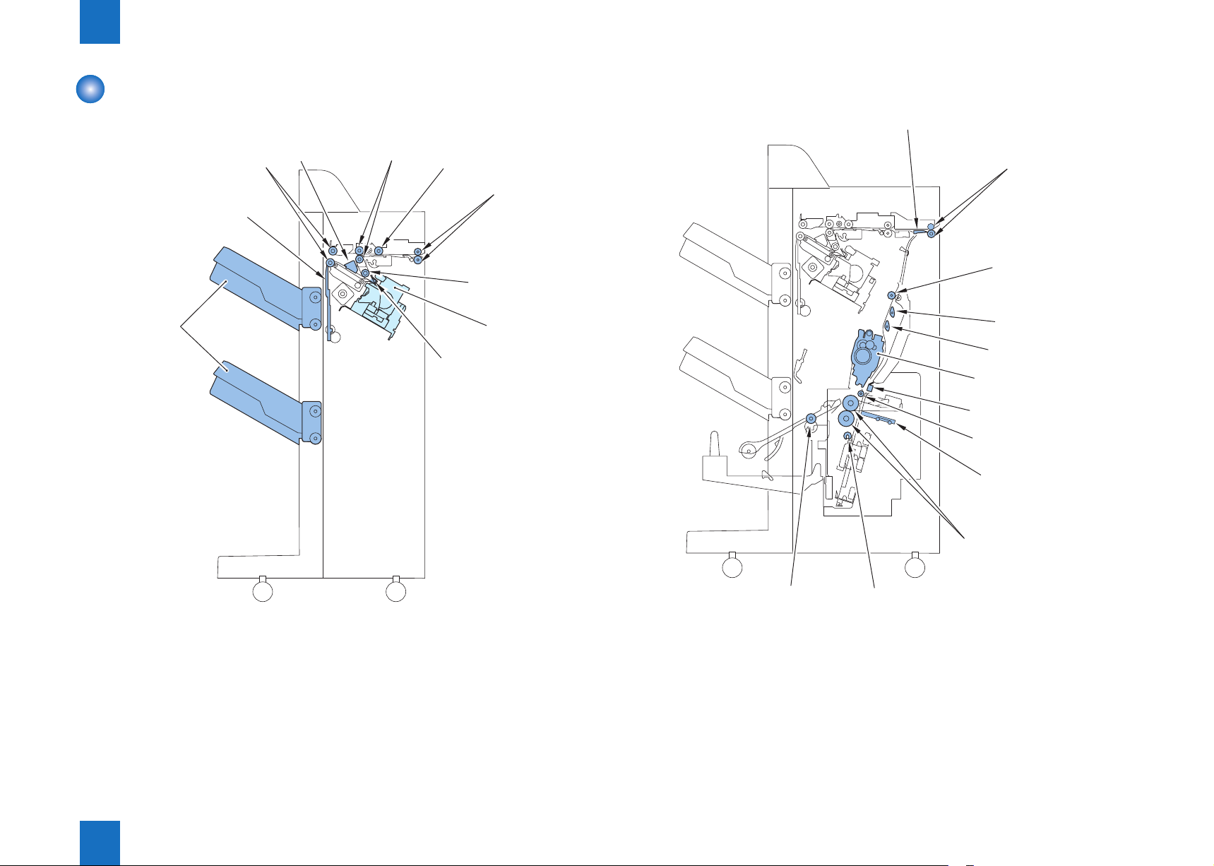
Cross Section
■Finisher Unit
Delivery tray
Stack delivery
roller
Shutter
Aligning plate 1st delivery roller
Buffer roller
Inlet roller
Return roller
Stapler
Rear end assist guide
■Saddle Unit
Saddle stitcher flapper
Inlet roller 1
Inlet roller 2
No.1 flapper
No.2 flapper
Stitcher (fromt,rear)
Stitcher mount
Holding roller
Paper pushing plate
Product Outline > Names of Parts > Cross Section > Saddle Unit
1
F-1-5
Saddle delivery roller
Paper folding roller
Crescent roller
F-1-6
1-7
1
Product Outline > Optional Construction
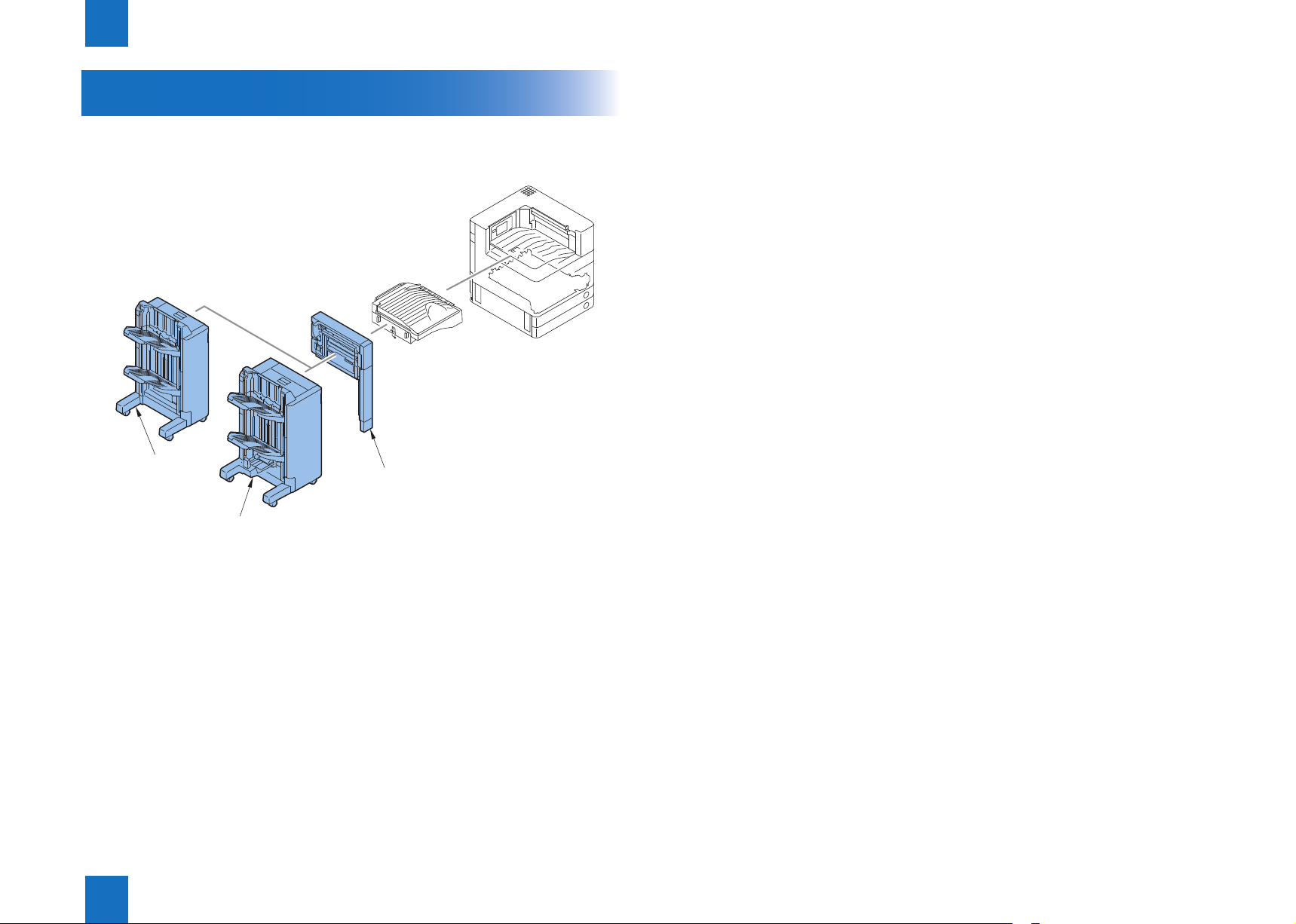
Optional Construction
The following optional machine can install to the nisher.
[1] External 2, 2/3, 2/4 , 4 Hole Puncher-B2
1-8
Staple finisher
Saddle finisher
Product Outline > Optional Construction
1
[1]
F-1-7
1-8
Technology
2
Basic Constitution
■
Controls
■
Feeding Unit
■
Processing Tray Unit
■
Stack Tray Unit
■
Saddle Stitcher Unit
■
Staple Operation
■
Detecting Jams
■
Power Supply
■
Work of Service
■
2
Technology
2
Technology > Basic Constitution > Component Conguration > Saddle Finisher (Booklet Finisher)
Basic Constitution
2-2
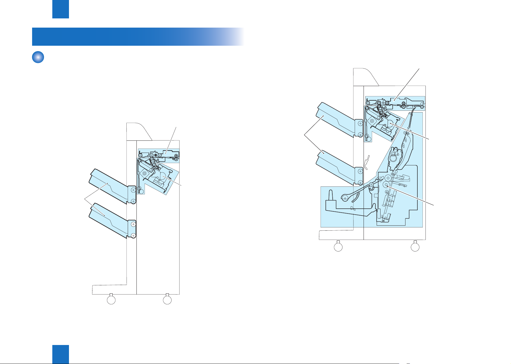
Component Conguration
The components of this saddle nisher are organized into 4 major blocks and this nisher are
organized into 3 major blocks; feed unit, processing unit, stack tray unit and saddle stitcher
unit.
■Finisher (Staple Finisher)
[Feed Unit]
[Processing Tray Unit]
[Stack Tray Unit]
■Saddle Finisher (Booklet Finisher)
[Stack Tray Unit]
[Feed Unit]
[Processing Tray Unit]
[Saddle Stitcher Unit]
F-2-1
Technology > Basic Constitution > Component Conguration > Saddle Finisher (Booklet Finisher)
2
F-2-2
2-2
2
Technology > Basic Constitution > Overview of the Electrical Circuitry (Saddle Stitcher Unit)
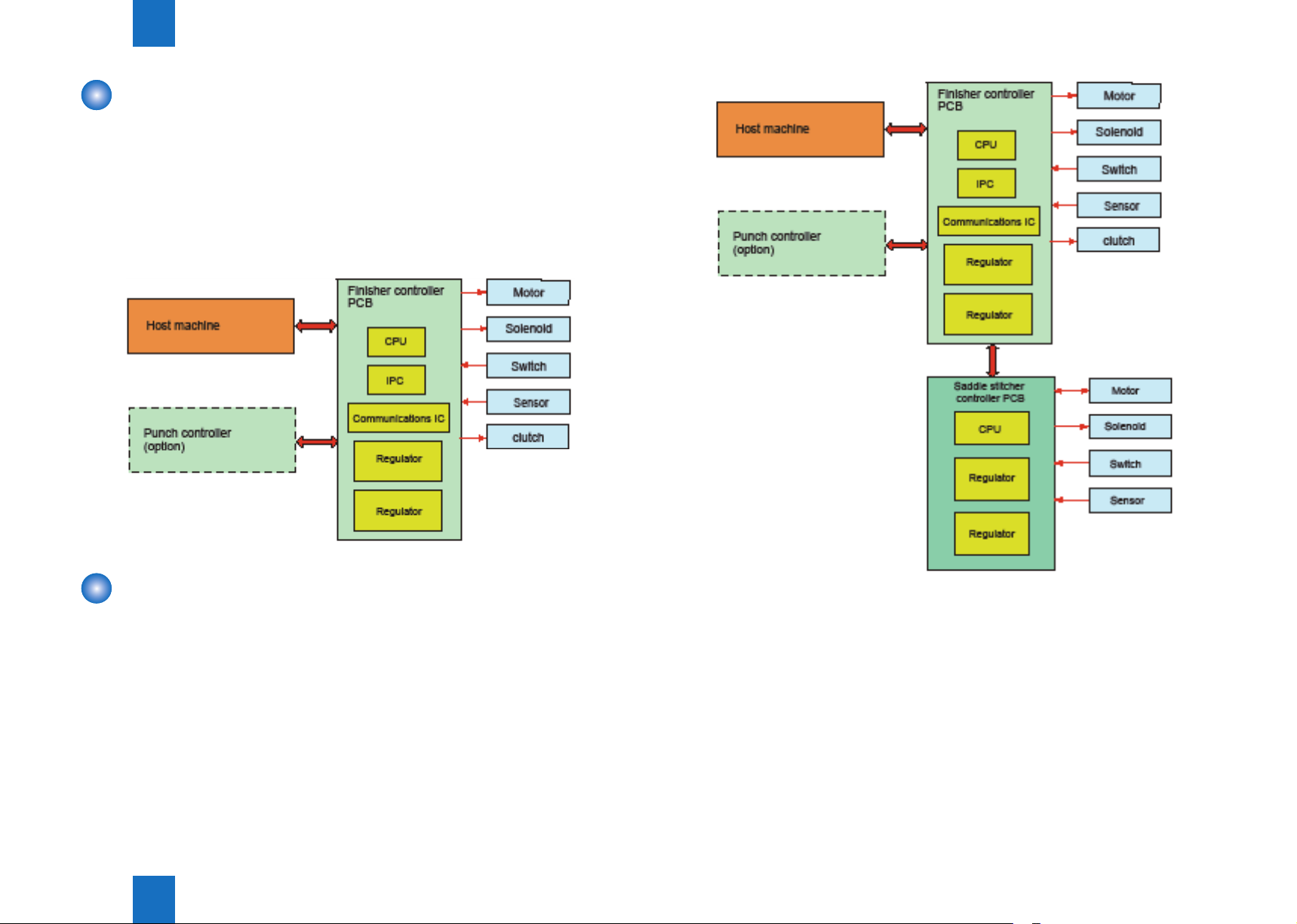
Overview of the Electrical Circuitry
The nisher’s sequence of operation is controlled by the nisher controller PCB. The nisher
controller PCB is a 16-bit microprocessor (CPU), and is used for communication with the host
machine (serial) in addition to controlling the nisher’s sequence of operations.
The nisher controller PCB responds to the various commands coming from the host machine
through a serial communications line to drive solenoids, motors, and other loads.
In addition, it communicates the nisher’s various states (information on sensors and
switches) to the host machine through a serial communications circuit.
2-3
F-2-3
Overview of the Electrical Circuitry (Saddle Stitcher Unit)
The sequence of operations used for the saddle stitcher is controlled by the saddle stitcher
controller PCB. The saddle stitcher controller PCB has a microprocessor.
This microprocessor is used to control the sequence of operations and to handle serial
communications with the nisher controller PCB, driving solenoids and motors
in response to the various commands from the nisher controller PCB.
The saddle stitcher controller PCB is also used to communicate the state of various sensors
and switches to the nisher controller PCB in serial.
Technology > Basic Constitution > Overview of the Electrical Circuitry (Saddle Stitcher Unit)
2
F-2-4
2-3

2
Controls
1.Feeding Unit
2.Stacking Trey
3. Process Tray
4.Saddle Stitcher
5.Staple
6.Detecting Jams
7.Power Supply
8.Work of service
Technology > Controls
2-4
Items Reference
Overview Refer to page 2-5
Construction Refer to page 2-6
Delivery path Refer to page 2-9
Tray operation Refer to page 2-12
Shutter operation Refer to page 2-13
Overview Refer to page 2-14
Basic operation Refer to page 2-14
Basic operation Refer to page 2-14
Controlling the Inlet Flappers Refer to page 2-20
Controlling the Movement of Sheets Refer to page 2-22
Controlling the Aligning the Sheets Refer to page 2-23
Controlling the Phase of the Crescent Roller Refer to page 2-25
Overview of Folding Operation Refer to page 2-26
Overview Refer to page 2-5
Stapler Unit Refer to page 2-30
Stitcher Unit Refer to page 2-36
Detecting Jams (Finisher Unit) Refer to page 2-37
Detecting Jams (Saddle Stitcher Unit) Refer to page 2-38
Power Supply Route (Finisher Unit) Refer to page 2-39
Power Supply Route (Saddle Stitcher Unit) Refer to page 2-39
User Maintenance Refer to page 2-40
Maintenance and Inspection Refer to page 2-40
Measures at Time of Parts Replacement. Refer to page 2-40
Upgrading Refer to page 2-40
T-2-1
Technology > Controls
2
2-4
2
Normal
Technology > Feeding Unit > Overview > Booklet Finisher
2-5
Feeding Unit
Overview
■Staple Finisher
The nisher is designed to operate according to the commands from its host machine to
deliver arriving copies to trays in the appropriate mode: simple stacking, job offset, stapling.
There are three delivery methods.
Method of delivery
Normal delivery tray
Normal
delivery
Simple stacking
Stack job offset
Staple
Front 1-point stapling
Rear 1-point stapling
2-point stapling
■Booklet Finisher
This product consists of the Finisher unit and the Saddle Stitcher unit.
The Finisher unit simply stacks sheets delivered from a host machine, offsets a stack job, or
staples and delivers the sheets to the trays according to commands delivered from a host
machine.
The Saddle Stitcher unit carries in, aligns, and stitches sheets delivered from the host
machine, and then feeds the resulting stack.
After these operations, it folds a stack of sheets and delivers it to the delivery trays of the
Saddle Stitcher unit.
There are four delivery methods.
Method of delivery
delivery
Saddle stitch delivery
Simple stacking
Stack job offset
Staple
Front 1-point stapling
Rear 1-point stapling
2-point stapling
Normal delivery tray
Technology > Feeding Unit > Overview > Booklet Finisher
2
F-2-5
2-5
2
Technology > Feeding Unit > Construction of the Control System > Staple Finisher
2-6
Construction of the Control System
■Staple Finisher
Normal delivery tray
Normal delivery tray
Saddle stitch
delivery tray
F-2-6
The copy sent from the host machine is delivered to the ejection tray or processing tray
according to the ejection type.
Job offset or stapling is performed, according to the instruction from the host machine, for
copy delivered to the staple tray.
When ejecting from the processing tray, rear end assist guide is used in addition to the stack
ejection roller to eject the stack.
The inlet motor (M101), stack ejection motor (M102), and rear end assist motor (M39) are
step motors.
These motors are rotated forward or backward by the microcomputer (CPU) in the nisher
controller PCB.
The following two sensors are provided in the copy delivery path to detect the arrival or
passing of copies.
-Inlet sensor (PI103)
-Delivery path sensor (PI104)
Also, each ejection tray has sensors to detect the presence of copy on the tray.
-First tray paper sensor (PI111)
-Second tray paper sensor (PI112)
If the copy does not reaches or passes each sensor within prescribed time, the nisher
controller PCB determines that the jam has occurred and stops the operation.
Then it noties the host machine that a jam has occurred.
When all of the doors are closed after xing the jam, the nisher checks whether copy is
detected by any of the above two sensors (inlet sensor, delivery path sensor).
If any of the sensors detects a copy, the nisher determines that the jam is not xed and
sends jam processing signal to the host machine once more.
Technology > Feeding Unit > Construction of the Control System > Staple Finisher
2
2-6
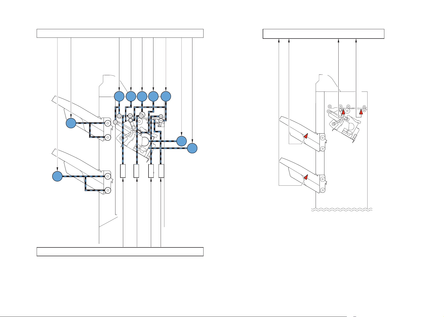
Finisher controller PCB (1/2)
Finisher controller PCB
First tray shift motor drive signal
Second tray shift motor drive signal
M107
M108
motor drive signal
Aligning plate front/rear
Stack ejection motor drive signal
M102 M101
SL103
Gear change motor drive signal
M103
M104
M110
SL102
M109
Inlet motor drive signal
Rear end assist motor drive signal
SL104
SL101
Stapler motor drive signal
Stapler drive motor drive signal
M105
M111
TRY2-P
TRY1-P
detection sensor
Delivery path paper
First tray paper detection sensor
Second tray paper detection sensor
TIMING
INLET
Inlet paper detection sensor
1st eject roller separation solenoid drive signal
DELIV-ROL-SL
Finisher controller PCB (2/2)
Inlet roller separation solenoid drive signal
Buffer roller separation solenoid drive signal
INLET-ROL-SL
BUFF-ROL-SL
Buffer rear end holding solenoid drive signal
BUFF-P-SL
F-2-8
F-2-7
2
Technology > Feeding Unit > Construction of the Control System > Booklet Finisher
2-8
■Booklet Finisher
The copy sent from the host machine is delivered to the ejection tray, processing tray, or
saddle stitcher according to the ejection type.
Job offset or stapling is performed, according to the instruction from the host machine, for
copy delivered to the staple tray.
When ejecting from the processing tray, rear end assist guide is used in addition to the stack
ejection roller to eject the stack.
The inlet motor (M101), stack ejection motor (M102), and rear end assist motor (M109) are
step motors.
These motors are rotated forward or backward by the microcomputer (CPU) in the nisher
controller PCB.
The following two sensors are provided in the copy delivery path to detect the arrival or
passing of copies.
-Inlet sensor (PI103)
-Delivery path sensor (PI104)
Also, each ejection tray has sensors to detect the presence of copy on the tray.
-First tray paper sensor (PI111)
-Second tray paper sensor (PI112)
If the copy does not reaches or passes each sensor within prescribed time, the nisher
controller PCB determines that the jam has occurred and stops the operation.
Then it noties the host machine that a jam has occurred.
When all of the doors are closed after xing the jam, the nisher checks whether copy is
detected by any of the above two sensors (inlet sensor, delivery path sensor).
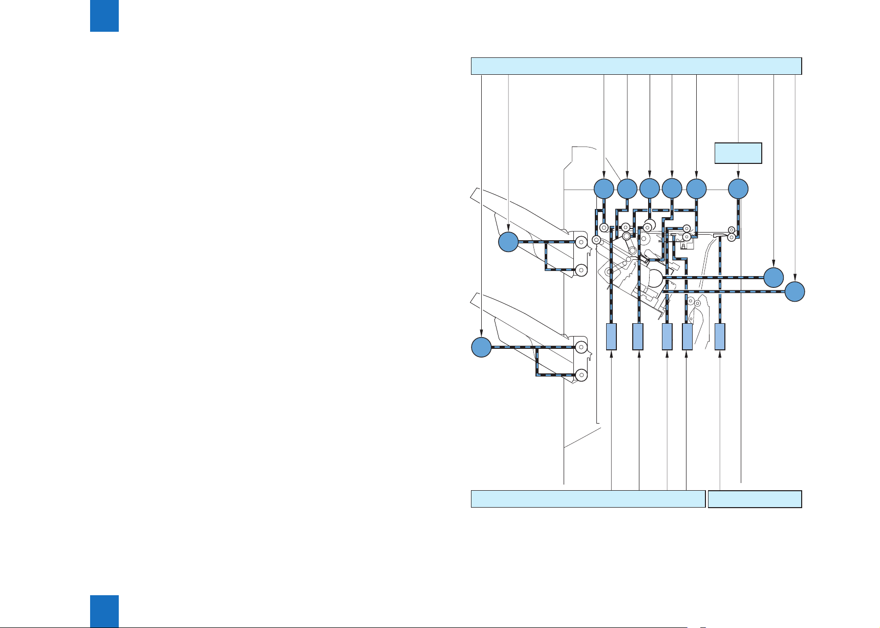
First tray shift motor drive signal
Second tray shift motor drive signal
M107
M108
Finisher controller PCB (1/2)
motor drive signal
Aligning plate front/rear
Stack ejection motor drive signal
M102 M101
SL103
Gear change motor drive signal
M103
M104
M110
M109
SL102
Rear end assist motor drive signal
SL101
Saddle inlet
motor drive signal
Inlet motor drive signal
Saddle driver
PCB
M9
SL104
SL5
Stapler motor drive signal
Stapler drive motor drive signal
M105
M111
Technology > Feeding Unit > Construction of the Control System > Booklet Finisher
2
1st eject roller separation solenoid drive signal
DELIV-ROL-SL
Finisher controller PCB (2/2)
Saddle inlet switching solenoid drive signal
Inlet roller separation solenoid drive signal
Buffer roller separation solenoid drive signal
INLET-ROL-SL
BUFF-ROL-SL
Buffer rear end holding solenoid drive signal
BUFF-P-SL
SDL-INLET-SL
Saddle stitcher
controller PCB
F-2-9
2-8
2
Technology > Feeding Unit > Paper Delivery Path > Straight Ejection
2-9
Second tray paper detection sensor TRY2-P
First tray paper detection sensor TRY1-P
Finisher controller PCB
TIMING
Delivery path paper detection sensor
Inlet paper detection sensor INLET
Paper Delivery Path
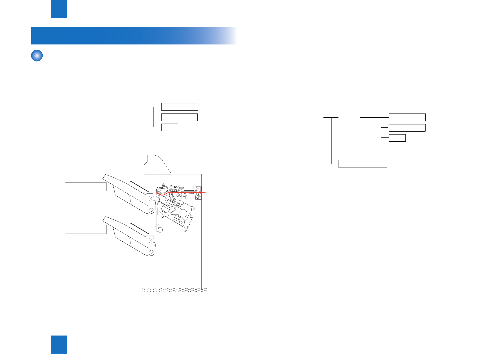
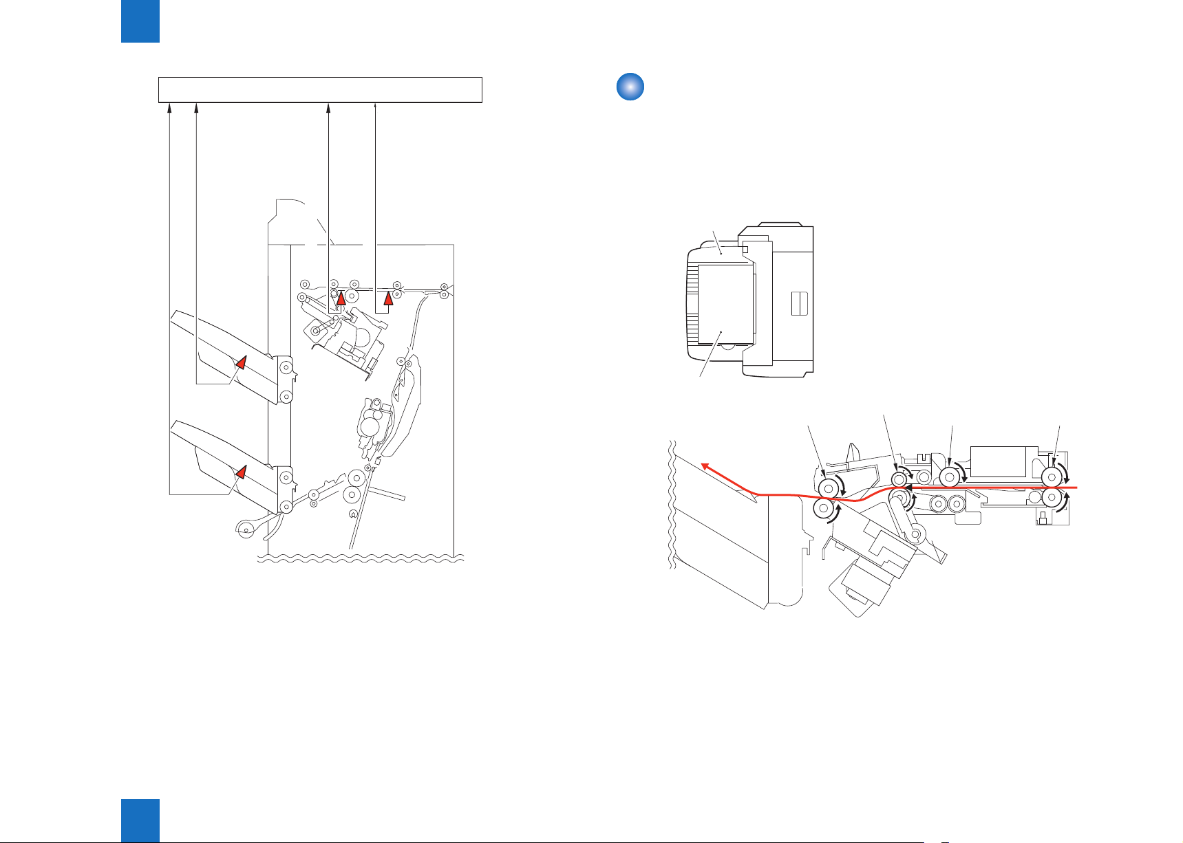
There are three ejection paths to tray 1 and 2 depending on the ejection processing.
Furthermore, Booklet Finisher has ejection paths for Saddle Stitcher Unit.
■Straight Ejection
When the equipment is set to non-sort, all copies are ejected through the following path.
Tray
Paper is stacked alternately
Stack ejection roller
1st delivery roller
Buffer roller
Inlet roller
Technology > Feeding Unit > Paper Delivery Path > Straight Ejection
2
F-2-10
F-2-11
2-9
2
Inlet roller
1st delivery
Technology > Feeding Unit > Paper Delivery Path > Buffer/Processing Tray Path
2-10
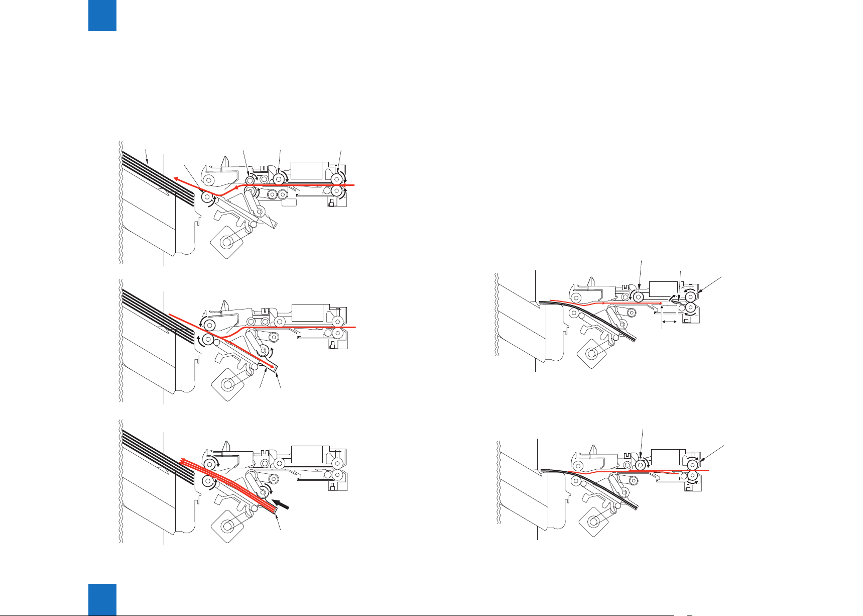
■Processing Tray Path
This is the copy ejection path when the equipment is set to sort for paper size other than A4,
B5, or LTR or when set to staple sort.
Copies are delivered to the processing tray for aligning and stapling. Then they are ejected
using the rear end assist.
Paper
Stack ejection
roller
roller
Buffer roller
■Buffer/Processing Tray Path
This is the copy ejection path when the equipment is set to sort for A4, B5, or LTR paper size.
Feed two sheets of paper to buffer (two or three sheets if 2-point stapling).
Then they are aligned and stapled in the processing tray and ejected.
Even while stapling or offset is being performed, simultaneous stack ejection, which
simultaneously ejects copies delivered to the buffer and post processed stack in the
processing tray, is performed because copies are received continuously from the host
machine.
The stack delivered from the buffer is ejected to the processing tray and the stack processed
in the processing tray is ejected to the tray.
Simultaneous stack ejection operation is described below for two A4 copies between stacks
when the equipment is set to sort.
1) When the 1st paper reaches the switchback point, it is sent to the buffer unit and the rear
end of the paper is held by the buffer guide.
Buffer roller
Buffer guide
20mm
Switch back
point
Inlet roller
Processing tray
Paper
Rear end assist
F-2-12
Technology > Feeding Unit > Paper Delivery Path > Buffer/Processing Tray Path
2
F-2-13
2) When the rst copy is delivered to the buffer, the second copy is delivered from the host
machine.
Buffer roller
Inlet roller
F-2-14
2-10
2
Technology > Feeding Unit > Paper Delivery Path > Paper Delivery Path (Saddle Stitcher Unit)
2-11
3) The rst delivery roller descends and works together with the stack delivery roller to deliver
the 1st and 2nd paper toward the processing tray.
At the same time,the stack in the processing tray is delivered toward the delivery tray by the
return roller and rear end assist guide.
Stack ejection roller
1st delivery roller
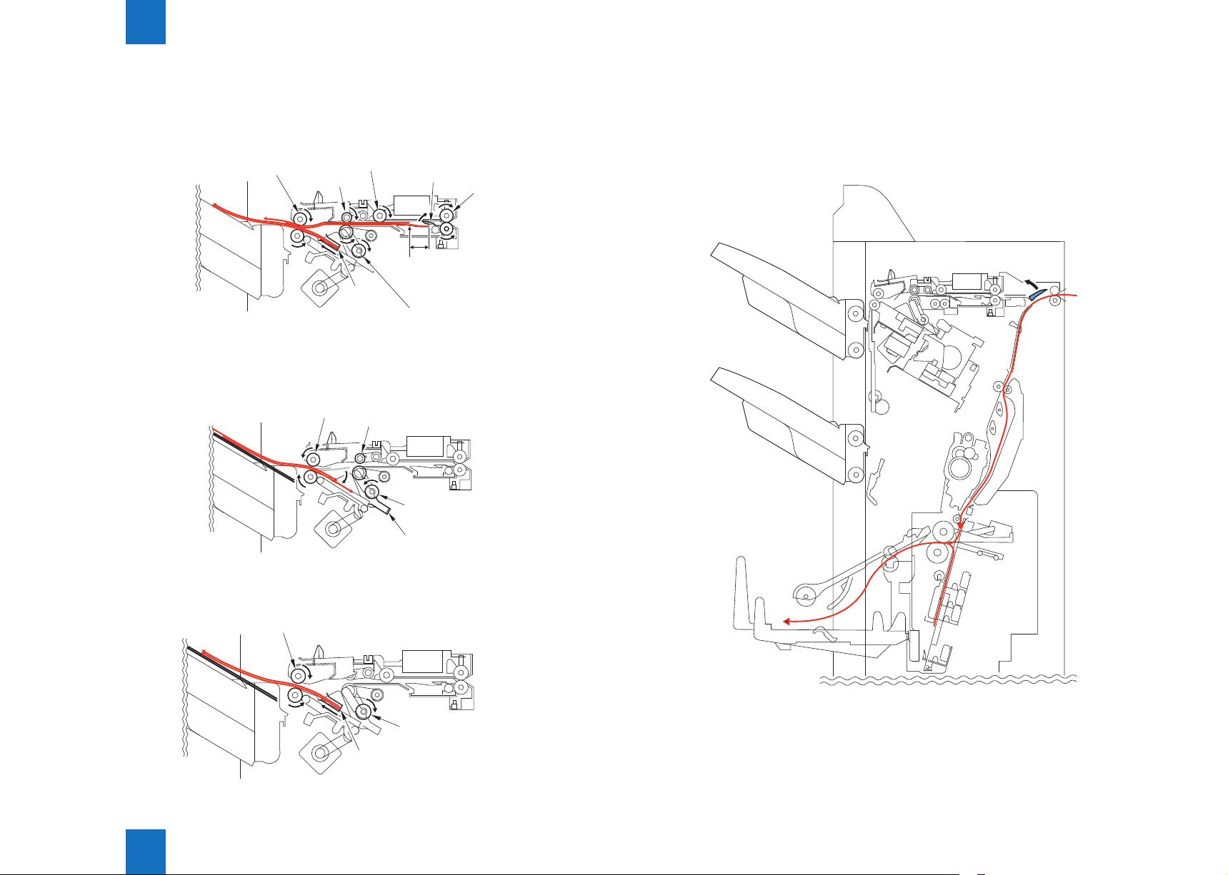
4) When the stack in the processing tray is delivered to the delivery tray and the rear end of
the 1st and 2nd paper exits the 1st delivery roller, the 1st and 2nd paper are delivered toward
the processing tray by the stack delivery roller and return roller.
Stack ejection roller
Buffer roller
Rear end
assist guide
1st delivery roller
Buffer guide
20mm
Switch back
point
Inlet roller
Return roller
F-2-15
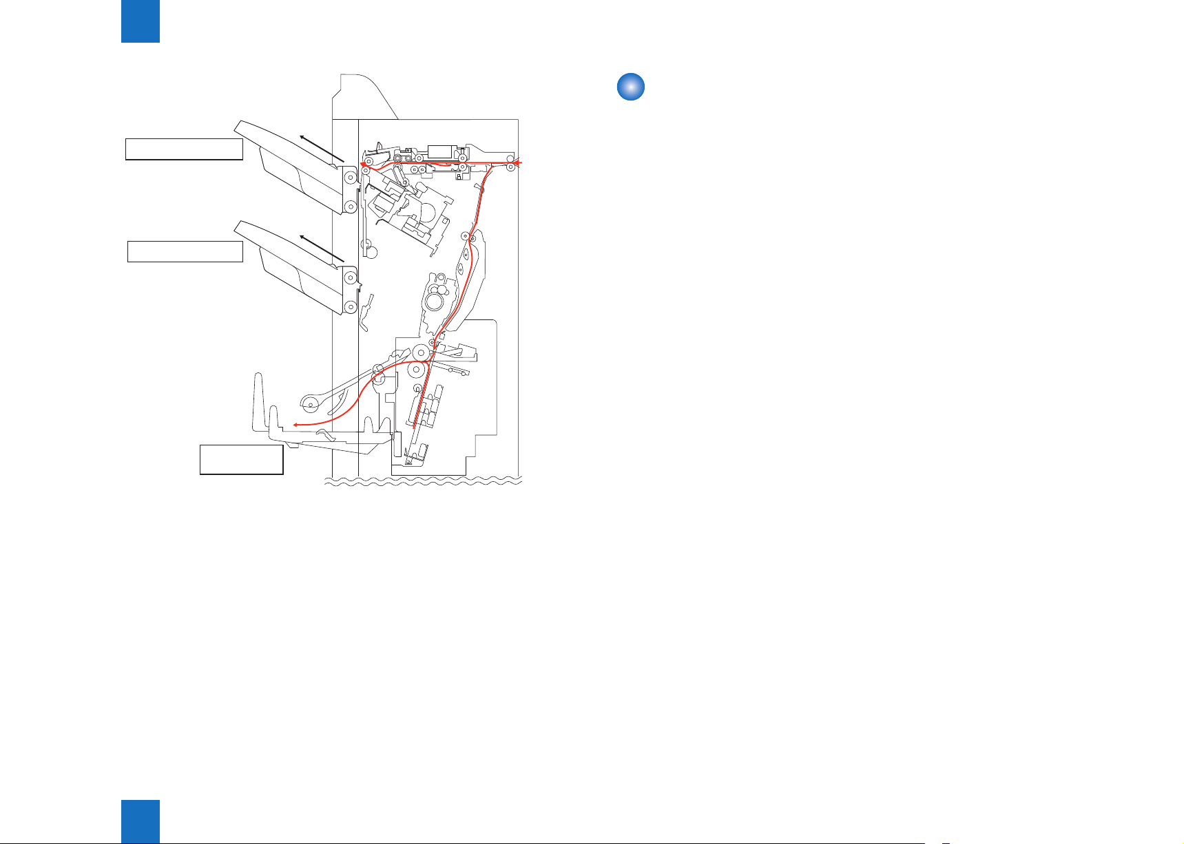
■Paper Delivery Path (Saddle Stitcher Unit)
A copy arriving in the nisher from the host machine is routed to the saddle stitcher by the
saddle stitcher apper.
The saddle stitcher executes stitching and saddling operations on the copy and then delivers
it to the saddle stitcher tray.
Return roller
Processing tray
F-2-16
5) The 1st and 2nd paper delivered to the processing tray are aligned and then delivered to
the delivery tray.
Stack ejection roller
Return roller
Rear end
assist guide
F-2-17
Technology > Feeding Unit > Paper Delivery Path > Paper Delivery Path (Saddle Stitcher Unit)
2
F-2-18
2-11
2
Technology > Stack Tray Unit > Tray Operation
2-12
Stack Tray Unit
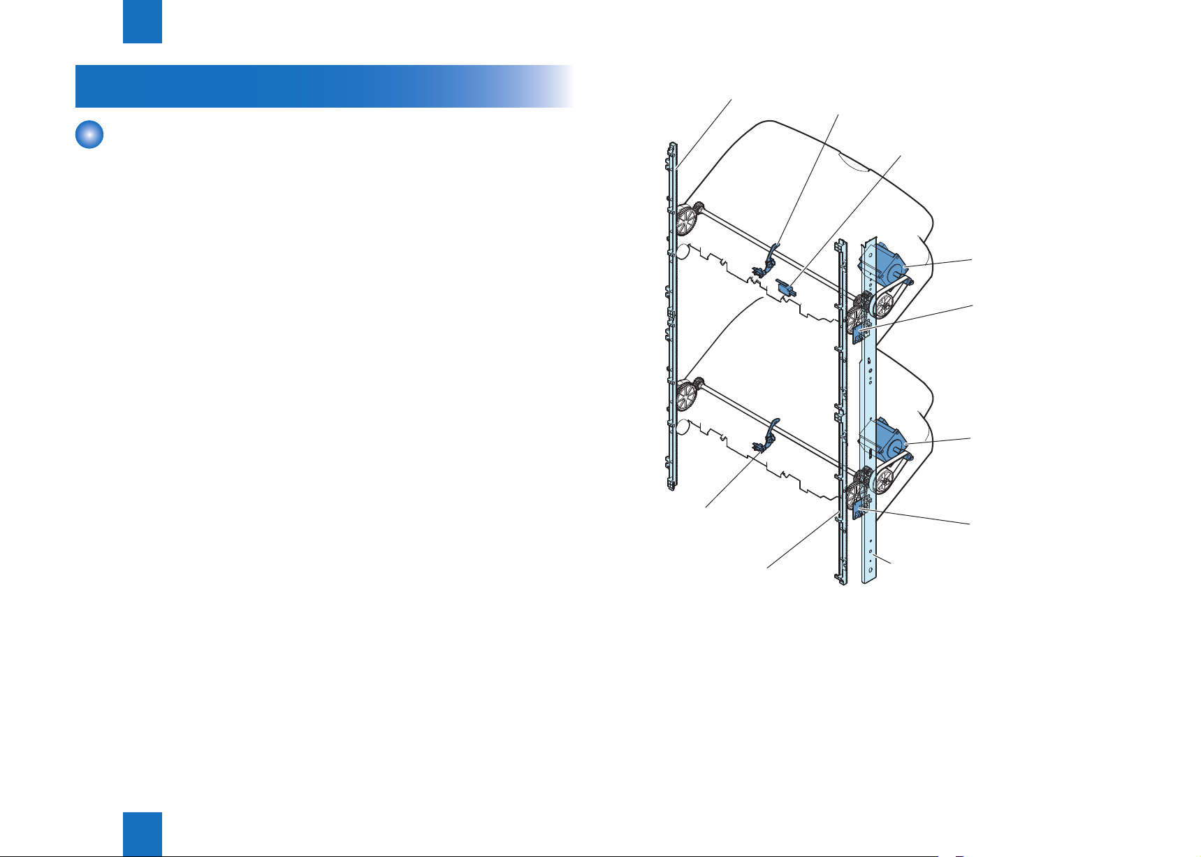
Tray Operation
This equipment has two delivery trays.
The upper tray is called tray 1 and the lower tray is called tray 2. The upper and lower tray
can move up and down independently.
The trays are moved up and down by the tray 1 shift motor (M107) and tray 2 shift
motor(M38).
Tray 1 paper sensor (PI111) and tray 2 paper sensor (PI112) are provided to detect the
presence of the paper stacked on the tray.
The home position of tray 1 is detected by the paper surface sensor (PI114) and the home
position of tray 2 is detected by the tray 2 paper surface sensor (PI115).
The home position is the top surface of the paper if papers are already stacked on the tray, or
the position where the edge of the tray is detected if no paper is stacked.
When the power is turned on, the nisher controller PCB drives the tray 1 shift motor (M107)
and tray 2 shift motor (M108) to return the tray to home position.
If the tray is already at home position, it is moved out of the home position once and then
returned to the home position once more.
If both tray 1 and tray 2 are at home position, this is performed for tray 1 and then for tray 2.
If the tray specied by the host machine is tray 2, the nisher controller PCB shifts the tray so
that
Tray 2 is at delivery port.
When paper is stacked on the tray, a prescribed number of pulses drive tray 1 shift motor
(M107) or tray 2 shift motor (M108) and the tray is lowered.
Then the tray returns to home position to prepare for the next stack.
The upper and lower limits of the tray are detected by three area sensors on tray 1 and tray 2
shift area sensor PCB.
The nisher controller PCB stops driving the tray 1 shift motor (M107) and tray 2 shift motor
(M108) when it detects the upper or lower limit of the tray.
Also, the ON/OFF combinations of the area sensors are used to detect over-stacking
according to the stack height for large size and mixed stacking.
The following gure shows the items detected with the ON/OFF combinations of the area
sensors.
The nisher controller PCB stops supplying +24V to the tray 1 shift motor (M37) and stops
the nisher operation when tray 1 switch (MSW103) turns ON.
Rack
Tray 2 paper surface
sensor (PI112)
Rack
Tray 1 paper surface sensor (PI111)
Tray 1 switch (MSW103)
Tray 1 shift motor(M107)
Tray 1 shift area
sensor PCB
Tray 2 shift motor
(M108)
Tray 2 shift area
sensor PCB
Light-shielding plate
F-2-19
Technology > Stack Tray Unit > Tray Operation
2
2-12
2
Technology > Stack Tray Unit > Shutter Operation
2-13
Paper surface sensor (PI114)
Tray 2 paper surface
sensor (PI115)
Detected items Tray 1 shift area sensor PCB
Tray 1 upper limit
Stack count 500 sheet limit exceeded
Stack count 1000 sheet limit
exceeded
Tray 1 lower limit
Paper surface sensor flag
Edge
Tray 1
Paper surface
sensor flag
Edge
Tray 2
Area sensor 1 Area sensor 2 Area sensor 3
(PCB4) (PCB4) (PCB4)
OFF OFF OFF
ON ON OFF
ON OFF OFF
ON OFF ON
Shutter Operation
When tray 1 passes the delivery section with paper already stacked, the stacked paper may
get caught by the delivery section.
A shutter is provided at the delivery section to prevent this.
The shutter closes when tray 1 passes the delivery section.
This is performed even when no paper is stacked.
When the shutter clutch (CL101) and stack ejection lower roller clutch (CL102) are ON, the
shutter moves up (close) when the stack ejection motor (M102) turns forward and moves
down (open, delivery enabled) when the motor turns backward.
The open/close of the shutter is detected by the shutter home position sensor (PI113).
Stack ejection lower roller clutch (CL102)
Stack ejection
roller (lower)
F-2-20
Stack ejection motor (M102)
Shutter home position
sensor (PI113)
T-2-2
Detected items Tray 2 shift area sensor PCB
Area sensor 1 Area sensor 2 Area sensor 3
(PCB5) (PCB5) (PCB5)
Tray 2 upper limit
Stack count 500 sheet limit
exceeded
Stack count 1000 sheet limit
exceeded
Tray 2 lower limit (nisher)
Tray 2 lower limit (saddle nisher)
* The symbol for the area sensor of each PCB is same because tray 1/tray 2 shift area sensor
PCBs are the same board.
Technology > Stack Tray Unit > Shutter Operation
OFF ON OFF
ON ON OFF
ON OFF OFF
OFF OFF OFF
OFF OFF ON
T-2-3
2
Shutter
Shutter clutch (CL101)
F-2-21
2-13
 Loading...