

Canon iR2200, iR2800, iR3300 Service Handbook

iR2200/iR2800/
iR3300
SERVICE
HANDBOOK
REVISION 0
MAY 2001
COPYRIGHT© 2001 CANON INC. CANON iR2200/iR2800/iR3300 REV.0 MAY 2001 PRINTED IN JAPAN (IMPRIME AU JAPON)
FY8-23BD-000

Application
This manual has been issued by Canon Inc. for qualified persons to learn technical theory, installation,
maintenance, and repair of products. This manual covers all localities where the products are sold. For
this reason, there may be information in this manual that does not apply to your locality.
Corrections
This manual may contain technical inaccuracies or typographical errors due to improvements or
changes in products. When changes occur in applicable products or in the contents of this manual,
Canon will release technical information as the need arises. In the event of major changes in the contents
of this manual over a long or short period, Canon will issue a new edition of this manual.
The following paragraph does not apply to any countries where such provisions are inconsistent with
local law.
Trademarks
The product names and company names used in this manual are the registered trademarks of the
individual companies.
Copyright
This manual is copyrighted with all rights reserved. Under the copyright laws, this manual may not be
copied, reproduced or translated into another language, in whole or in part, without the written consent
of Canon Inc.
COPYRIGHT © 2001 CANON INC.
Printed in Japan
Imprimé au Japon
Caution
Use of this manual should be strictly supervised to avoid disclosure of
confidential information.
COPYRIGHT© 2001 CANON INC. CANON iR2200/iR2800/iR3300 REV.0 MAY 2001 PRINTED IN JAPAN (IMPRIME AU JAPON)

CONTENTS
Contents
CHAPTER 1 MAINTENANCE AND INSPECTION
1 Periodically Replaced Parts.............. 1-1
1.1 Reader Unit ................................ 1-1
1.2 Printer Unit ................................ 1-1
1.3 Side Paper Deck.........................1-1
1.4 Cassette Feeding unit ................. 1-1
1.5 Inner 2-Way Tray ....................... 1-1
2 Consumables and Durables .............. 1-2
2.1 Checking the Time of Replacement
................................................... 1-2
2.2 Reader Unit ................................ 1-2
2.3 Printer Unit ................................ 1-2
2.4 Side Paper Deck.........................1-3
CHAPTER 2
1 Making lnitial Checks ...................... 2-1
2 Checking the Scanner Side............... 2-1
3 Checking the Printer Side (1/3)........2-2
IMAGE ADJUSTMENT BASIC PROCEDURE
2.5 Cassette Feeding Unit ................ 1-3
2.6 Inner 2-Way Tray-A1.................1-3
3 Periodical Servicing Procedure ........ 1-4
4 Scheduled Servicing Chart ............... 1-6
4.1 Reader Unit ................................ 1-6
4.2 Printer Unit ................................ 1-7
5 Points to Note for Scheduled Servicing
.......................................................... 1-8
6 Cleaning the Bottom of the Developing
Assembly..........................................1-9
6.1 Cleaning the Bottom of the Devel-
oping Assembly.......................... 1-9
4 Checking the Printer Side (2/3)........2-2
5 Checking the Printer Side (3/3)........2-2
CHAPTER 3 STANDARDS AND ADJUSTMENTS
1 Image Adjustments........................... 3-1
1.1 Standards of Image Position ...... 3-1
1.2 Checking the Image Position ..... 3-2
1.3 Adjusting Left/Right lamge Margin
................................................... 3-3
1.3.1 Adjusting the Registration for
the Cassette Rear Front........ 3-3
1.3.2 Adjusting the Registration for
the Multifeeder Rear Front
............................................. 3-4
1.3.3 Adjusting the Registration for
the Deck ............................... 3-4
1.3.4 Duplex Feeding Unit ........... 3-5
1.4 Adjusting the Image Leading Edge
Margin........................................ 3-5
1.5 Adjusting the Left/Right Non-Image
Width.......................................... 3-5
1.6 Adjusting the Leading Edge Non-
Image Width............................... 3-6
2 Scanning System .............................. 3-6
2.1 After Replacing the Scanning Lamp
................................................... 3-6
2.2 Mounting the Motor Unit........... 3-7
2.3 Routing the Scanner Drive Cable
................................................... 3-8
2.4 Adjusting the Position of the No. 1/
No. 2 Mirror Base ...................... 3-9
2.5 Mounting the Copyboard Glass
................................................. 3-11
2.6 Mounting the Reader Upper Frame
................................................. 3-12

CONTENTS
2.7 Points to Note When Replacing the
CCD Unit ................................. 3-12
2.8 When Replacing the Reader Con-
troller PCB ............................... 3-12
3 Image Formation System ............... 3-13
3.1 Positioning the Developing Assem-
bly Magnetic Seal .................... 3-13
3.2 Mounting the Developing Assembly
Blade ........................................ 3-13
3.3 Removing the Paper Lint ......... 3-14
3.4 Cleaning the Waste Toner Case
................................................. 3-15
4 Fixing System................................. 3-16
4.1 Mounting the Locking Cam Unit
................................................. 3-16
5 Paper Deck ..................................... 3-17
5.1 Mounting the Front Cover ....... 3-17
5.2 Adjusting the Paper Level Indicator
................................................. 3-18
5.3 Adjusting the Position of the Sup-
port Member ............................ 3-18
5.4 Mounting the Deck Pickup Roller
................................................. 3-19
5.5 Removing the Deck Pickup/Feeding
Roller ....................................... 3-19
5.6 Orientation of the Deck Pickup/
Feeding Roller.......................... 3-20
5.7 Adjusting the Deck Separation
Roller Pressure ......................... 3-20
5.8 Position of the Deck Pickup Roller
Releasing Solenoid (SL1D) ..... 3-21
5.9 Adjusting the Height of the Side
Member .................................... 3-22
5.9.1 Before Making Adjustments
........................................... 3-22
5.9.2 Making Adjustments.......... 3-22
6 Cassette Feeding Unit-W1 ............. 3-23
6.1 Mounting the Pedestal Main Motor
................................................. 3-23
7 Envelope Feeder Attachment.......... 3-24
7.1 Envelopes and Type of Spring
................................................. 3-24
7.2 Replacing the Spring................ 3-24
7.2.1 Replacing the Spring ......... 3-24
7.3 Changing the Size .................... 3-25
7.3.1 Changing the Size .............. 3-25
CHAPTER 4 TROUBLESHOOTING IMAGE FAULTS/
MALFUNCTIONS
1 Making Initial Checks ...................... 4-1
1.1 Checking the Site of Installation
................................................... 4-1
1.2 Checking the Originals .............. 4-1
1.3 Checking the ADF Platen,
Copyboard cover, and Copyboard
glass (standard white plate)........ 4-1
1.4 Charging Roller and Static Elimina-
tor ............................................... 4-2
1.5 Checking the Developing Assembly
................................................... 4-2
1.6 Checking the Paper .................... 4-2
1.7 Checking the Periodically Replaced
Parts............................................ 4-2
1.8 Image Adjustment Basic Procedure
................................................... 4-2
1.9 Others .........................................4-3
2 Samples of Image Faults .................. 4-6
3 Troubleshooting Image Faults.......... 4-7
3.1 The copy is too light (halftone area
only) ........................................... 4-7
3.2 The copy is too light (including
solid black)................................. 4-8
3.3 The copy is too light (entire face,
considerable) ............................ 4-10
3.4 The copy has uneven density
(darker at front) ........................ 4-12
3.5 The copy has uneven density
(lighter at front)........................ 4-12

CONTENTS
3.6 The copy is foggy (entire face)
................................................. 4-13
3.7 The copy is foggy (vertical).....4-14
3.8 The copy has a black line (vertical,
fuzzy, thick) ............................. 4-14
3.9 The copy has a black line (vertical,
fine) .......................................... 4-15
3.10 The copy has a white spot (vertical)
................................................. 4-16
3.11 The copy has a white line (vertical)
................................................. 4-16
3.12 The copy has a white spot (horizon-
tal) ............................................ 4-17
3.13 The back of the copy is soiled/
Soiled edge............................... 4-18
3.14 The copy has a fixing fault....... 4-19
3.15 The copy has a displaced leading
edge .......................................... 4-20
3.16 The copy has a displaced leading
edge (large margin) .................. 4-20
3.17 The copy has a displaced margin
(no margin)............................... 4-20
3.18 The copy is blurred .................. 4-21
3.19 The copy is foggy (horizontal)
................................................. 4-22
3.20 The copy has inadequate sharpness
................................................. 4-23
3.21 The copy is completely blank
................................................. 4-24
3.22 The copy is completely black
................................................. 4-26
3.23 The copy has a block/white dot after
replacement of the drum unit
................................................. 4-27
3.24 The copy has a black line (stream
reading) .................................... 4-27
4 Troubleshooting Malfunctions ....... 4-28
4.1 Power Supply System .............. 4-28
4.1.1 The AC power is absent ..... 4-28
4.1.2 The DC power is absent
........................................... 4-29
4.2 Printer Unit .............................. 4-30
4.2.1 Pickup fails ........................ 4-30
4.2.2 The lifter fails to move up
(pickup from the cassette)
........................................... 4-31
4.2.3 The vertical path roller fails to
rotate .................................. 4-32
4.2.4 The registration roller fails to
rotate .................................. 4-32
4.2.5 Pickup from the multifeeder
tray fails (i.e., the pickup roller
fails to rotate)..................... 4-33
4.2.6 Pickup from the multifeeder
tray fails (i.e., the multifeeder
holding plate fails to move up)
........................................... 4-33
4.2.7 The photosensitive drum fails to
rotate .................................. 4-34
4.2.8 The pre-exposure lamp fails to
go ON ................................ 4-34
4.3 Reader Unit .............................. 4-35
4.3.1 The No. 1 mirror base fails to
move .................................. 4-35
4.3.2 The scanning lamp fails to go
ON ..................................... 4-36
4.4 Message Indication .................. 4-37
4.4.1 The “Add Toner” message fails
to go OFF........................... 4-37
4.4.2 The “Control Card Set” message fails to go OFF (when no
card reader is installed)...... 4-37
4.4.3 The “Add Paper” message fails
to go OFF........................... 4-37
4.4.4 The “Close the Front Cover”
massage fails to go OFF ..... 4-38
4.5 Paper Deck ............................... 4-39
4.5.1 Pickup fails ........................ 4-39
4.5.2 The deck lifter fails to move up
........................................... 4-40
5 Troubleshooting Feeding Faults ...... 4-41
5.1 Paper Jams ............................... 4-41
5.1.1 Pickup Assembly ............... 4-42
5.1.2 Separation/Feeding Assembly
........................................... 4-43
5.1.3 Fixing/Delivery Assembly, Duplex Reversing Assembly
........................................... 4-43

CONTENTS
5.1.4 Duplex Feeding Assembly
........................................... 4-44
5.2 Faulty Feeding ......................... 4-45
5.2.1 Double Feeding ................. 4-45
5.2.2 Wrinkles ............................ 4-45
6 Outline of Electrical Components
........................................................ 4-46
6.1 Introduction.............................. 4-46
6.1.1 Guide to the List ................ 4-46
6.1.2 Checking the Photointerrupters
........................................... 4-47
6.2 E201 (reader unit/printer unit) . 4-48
6.2.1 Clutches ............................. 4-48
6.2.2 Solenoids, Switches ........... 4-48
6.2.3 Motors (1/2) ....................... 4-50
6.2.3 Motors (2/2) ....................... 4-52
6.2.4 Fans.................................... 4-54
6.2.5 Sensors (1/3) ...................... 4-56
6.2.5 Sensors (2/3) ...................... 4-58
6.2.5 Sensors (3/3) ...................... 4-60
6.2.6 Lamps, Heaters, and Others
........................................... 4-62
6.2.7 PCBs .................................. 4-64
6.3 Side Paper Deck-L1 ................. 4-66
6.3.1 Clutches ............................. 4-66
6.3.2 Solenoids, and Switches ..... 4-66
6.3.3 Motors................................ 4-66
6.3.4 Sensors............................... 4-68
6.3.5 PCBs .................................. 4-68
6.4 2-Cassette Feeding Unit-W1
................................................. 4-70
6.4.1 Clutches ............................. 4-70
6.4.2 Solenoids and Switches ..... 4-70
6.4.3 Motors................................ 4-70
6.4.4 Sensors............................... 4-72
6.4.5 PCBs .................................. 4-72
6.5 Inner 2-Way Tray-A1...............4-74
6.5.1 Solenoids ........................... 4-74
6.5.2 Motors................................ 4-74
6.5.3 Sensors............................... 4-74
6.6 Super G3 FAX Board-J1 .......... 4-76
6.6.1 Others ................................ 4-76
6.6.2 PCBs .................................. 4-76
6.7 Variable Resistors (VR), Light-
Emitting Diodes, and Check Pins by
PCB .......................................... 4-78
6.7.1 Main Controller PCB......... 4-79
6.7.2 DC Controller PCB............ 4-80
6.7.3 Reader Controller PCB ...... 4-80
6.7.4 Composite Power Supply PCB
........................................... 4-81
6.7.5 Fixing Film Sensor PCB
........................................... 4-81
CHAPTER 5 SERVICE MODE
1 Outline of Service Mode .................. 5-1
1.1 Outline ....................................... 5-1
1.2 Starting Service Mode and Making
Selections ................................... 5-2
1.3 Ending Service Mode................. 5-3
1.4 Backing Up Service Mode ......... 5-3
1.5 Using Service Mode................... 5-4
1.5.1 Initial Screen........................ 5-4
1.5.2 Level 1/Level 2 Item Screen
............................................. 5-4
1.5.3 Level 3 Item Screen ............. 5-5
2 DISPLAY Control Display Mode...... 5-6
2.1 COPIER ..................................... 5-6
2.2 FEEDER .................................. 5-19
3 I/O, I/O Display mode....................5-20
3.1 DC-CON .................................. 5-21
3.2 R-CON ..................................... 5-28
3.3 MN-CON ................................. 5-31
3.4 FEEDER .................................. 5-33
3.5 SORTER .................................. 5-35
4 ADJUST Adjustment Mode ........... 5-44
4.1 COPIER ................................... 5-44
4.2 FEEDER .................................. 5-58
4.3 SOR TER .................................. 5-59
5 FUNCTION Operation/Inspection
3.5.1 Finisher-J1 ......................... 5-35
3.5.2 Saddle Finisher-G1 ............ 5-38
3.5.3 Puncher Unit (Saddle Finisher-
G1) ..................................... 5-41
Mode .............................................. 5-61

CONTENTS
5.1 COPIER ................................... 5-61
6 OPTION Machine Settings Mode
........................................................ 5-81
6.1 COPIER ................................... 5-81
6.2 FEEDER .................................. 5-94
6.3 SORTER .................................. 5-94
6.4 BOARD.................................... 5-95
7 TEST Test Print Mode ................... 5-98
8 COUNTER Counter Mode........... 5-100
CHAPTER 6 SELF DIAGNOSIS
1 Self Diagnosis .................................. 6-1
1.1 Detail Codes (copier) ................. 6-3
1.2 ADF Error Codes ..................... 6-37
1.3 Saddle Finisher-G1 Error Codes
................................................. 6-38
1.3.1 Error Code of the Finisher Unit
1.4 Finisher-J1 Error Codes ........... 6-43
CHAPTER 7 UPGRADING
1 Upgrading......................................... 7-1
1.1 Outline ....................................... 7-1
1.1.1 Download Mode .................. 7-1
1.1.2 Making Pre-Checks ............. 7-2
1.2 Data Control............................... 7-5
1.3 Downloading the System Software,
RUI, and Language Module....... 7-8
1.3.1 Making Connections............ 7-8
1.3.2 Downloading ....................... 7-8
1.3.3 After Downloading ............ 7-14
1.4 Upgr ading the BOOT ROM...... 7-14
1.4.1 Making Preparations.......... 7-14
1.4.2 Connection......................... 7-15
1.4.3 Preparing BOOT ROM ......7-15
1.4.4 After Downloading ............ 7-19
1.5 Formatting the HDD ................ 7-20
1.5.1 Making Connections.......... 7-20
1.5.2 Starting Formatting............ 7-20
1.5.3 Points to Note When Formatting
1.6 Downloader PCB ..................... 7-27
1.6.1 Purpose .............................. 7-27
1.6.2 Downloader PCB Components
1.6.3 Download Procedure ......... 7-28
1.6.4 Disconnecting .................... 7-32
1.7 Upgrading by Replacing the
2 Backing Up Data ............................ 7-34
2.1 Outline ..................................... 7-34
2.2 Backing Up Data...................... 7-35
2.2.1 Making Preparations.......... 7-35
2.2.2 Making Connections.......... 7-35
2.2.3 Backing Up Data ............... 7-36
2.2.4 Downloading Backup Data
2.2.5 Managing Backup Data ..... 7-45
................................................. 6-38
the Hard Disk..................... 7-26
........................................... 7-27
DIMM/ROM ............................ 7-33
........................................... 7-41
APPENDIX
A. General Timing Chart...................... A-1
B. General Circuit Diagram ................. A-3
C. Side Paper Deck-L1 General Circuit
Diagram........................................... A-5
D. 2-Cassette Feeding Unit-W1 General
Circuit Diagram............................... A-6
E. Inner 2-Way Tray-A1 General Circuit
Diagram........................................... A-7
F. Specifications .................................. A-8
1 Main Body ................................ A-8
1.1 Type .................................... A-8
1.2 Systems ............................... A-8

CONTENTS
1.3 Functions ............................ A-9
1.4 Others ............................... A-12
2 Side Paper Deck-L1 ................ A-15
2.1 Systems ............................. A-15
3 Cassette Feeding Unit-W1 ...... A-16
3.1 Systems ............................. A-16
4 Inner 2way Tray-A1 ................ A-17
4.1 Type .................................. A-17
5 Envelope Feeder Attachment-B1
................................................ A-18
5.1 Systems ............................. A-18
5.2 Envelopes.......................... A-19
5.3 Guaranteed Image Area .... A-20
G. List of Special Tools ...................... A-21
H. List of Solvents/Oils...................... A-23

CHAPTER 1 MAINTENANCE AND INSPECTION
CHAPTER 1 MAINTENACE AND INSPECTION
1 Periodically Replaced Parts
Some of the parts used in the machine must be replaced on a periodical basis to ensure a
specific level of product performance; be sure to replace them as indicated, as they will affect the machine functions appreciably once they fail.
If possible, plan the replacement to coincide with a scheduled visit to the user’s.
The estimates are subject to change depending on the conditions of the site
of installation or how the machine is used.
1.1 Reader Unit
The reader unit does not have parts that require periodical replacement.
1
1.2 Printer Unit
The printer unit does not have parts that require periodical replacement.
1.3 Side Paper Deck
The side paper deck does not have parts that require periodical replacement.
1.4 Cassette Feeding unit
The cassette feeding unit does not have parts that require periodical replacement.
1.5 Inner 2-Way Tray
The inner 2-way tray does not have parts that require periodical replacement.
1-1

CHAPTER 1 MAINTENANCE AND INSPECTION
2 Consumables and Durables
Some parts of the machine may require replacement over the period of product warranty
because of wear or damage. Replace them as needed.
2.1 Checking the Time of Replacement
Use service mode to find out when to replace a specific part:
COPIER>COUNTER>DRBL-2.
2.2 Reader Unit
The reader unit does not have parts designated as a durable.
2.3 Printer Unit
As of March 2001
No. Part name Part No. Q’ty Life (prints) Remarks
1 Transfer roller FF6-0104 1 240,000
2 Transfer static eliminator FF5-7246 1 240,000
3 Developing cylinder FG6-5714 1 480,000
4 Fixing cleaning roller FG6-5709 1 150,000
5 Pre-exposure lamp FG5-6297 1 240,000
6 Pickup roller FF5-4552-020 2 120,000 Actual prints made
7 Feeding roller FF5-4552-020 2 120,000 Actual prints made
8 Separation roller FF5-4634-020 2 120,000 Actual prints made
9 Pickup roller FB1-8581 1 240,000 Actual prints made
(multifeeder)
10 Separation pad FE5-4132 1 240,000 Actual prints made
(multifeeder)
11 Fixing film unit (100V) FG6-5712 1 150,000
12 Fixing film unit (115V) FG6-6039 1 150,000
13 Fixing film unit (230V) FG6-6041 1 150,000
1-2
T01-203-01

CHAPTER 1 MAINTENANCE AND INSPECTION
2.4 Side Paper Deck
As of March 2001
No. Part name Part No. Q’ty Life (prints) Remarks
1 Pickup roller (front) FF5-7830 1 240,000 Actual prints made
2 Pickup roller (rear) FF5-7829 1 240,000 Actual prints made
3 Feeding roller FF5-7541 1 240,000 Actual prints made
4 Separation roller FB2-7777-020 1 240,000 Actual prints made
T01-204-01
2.5 Cassette Feeding Unit
As of March 2001
No. Part name Part No. Q’ty Life (prints) Remarks
1 Pickup roller FF5-4552-020 2 120,000 Actual prints
2 Feeding roller FF5-4552-020 2 120,000 Actual prints
3 Separation roller FF5-4634-020 2 120,000 Actual prints
T01-205-01
2.6 Inner 2-Way Tray-A1
The inner 2-way tray-A1 does not have parts that are designated as a durable.
1-3

CHAPTER 1 MAINTENANCE AND INSPECTION
3 Periodical Ser vicing Procedure
1. As a rule, provide periodical servicing every 120,000 prints.
2. Before setting out on a scheduled visit, check the Service Book, and
take any parts that may require replacement.
As of June 2001
Work Procedure
1. Report to the person in charge, and check the general condition.
2. Record the counter reading, and check the faulty prints.
3. Make test prints, and check them for the following: (1) image density, (2) w hite background for soiling, (3) characters for clarity, (4) margin, (5) fixing, registration, and back
for soiling.
The margin must meet the following standards:
Leading edge: 2.5 ± 1.5 mm
Left edge: 2.5 ± 1.5 mm
Right edge: 0.5 mm or more
Trailing edge: 2.5 +1.1, -1.7 mm (smaller than B4) <2.5 ± 2.0 mm>
3.5 +0.6, -2.8 mm (B4 or larger) <3.5 ± 2.0 mm>
5.5 +1.5, -5.0 mm (free size)
< >: when the DADF-H1 picks up an original
(in stream readig mode).
4. Optical Unit
Clean the following using a blower brush to clean; if the dirt is excessive, use alcohol:
(1) No. 1/2/3 mirror, (2) original illuminating reflecting plate, (3) lens, (4) original size
sensor.
5. Scanner Drive System
(1) Scanner cable; check the tension, and adjust as necessary. Inspect and adjust the scan-
ner cable only when the machine has made the first 250,000 prints.
(2) Scanner rail; clean the slide area, and apply silicone oil (FY9-6011).
1-4

CHAPTER 1 MAINTENANCE AND INSPECTION
6. Feeding System
Clean the following: (1) feeding assembly base, (2) fixing inlet guide (upper, lower), (3)
transfer guide, (4) pre-registration assembly (paper lint).
7. Image Formation System
Clean the following: developing member, (2) developing assembly bottom.
8. Optical Unit
Clean the following with a special tool: (1) bending mirror.
9. Image Formation System
Inspect and, as necessary, remove the waste toner and then clean the waste toner case;
or, replace the waste toner case if any:
1. Be sure to dispose of the water toner according to the standards imposed by the government concerned.
2. Do not dispose of waste toner into fire (to avoid explosion).
10. Make test copies.
11. Make sample copies.
12. Check the operation of the leakage breaker.
While the power switch is ON, press the test switch of the leakage breaker to make sure
that it operates normally (i.e., the lever goes OFF to cut the power).
If the leakage breaker fails to operate normally, replace it and make a check once again.
To reset,
After making a check, turn off the main power switch (the lever should go ON), and then
turn on the main power switch.
13. Put the sample copies into order, and clean up the area around the machine.
14. Fill out the Service Book, and report to the person in charge; put a description of the
check made on the operation of the leakage breaker in the Service Book.
1-5
CHAPTER 1 MAINTENANCE AND INSPECTION
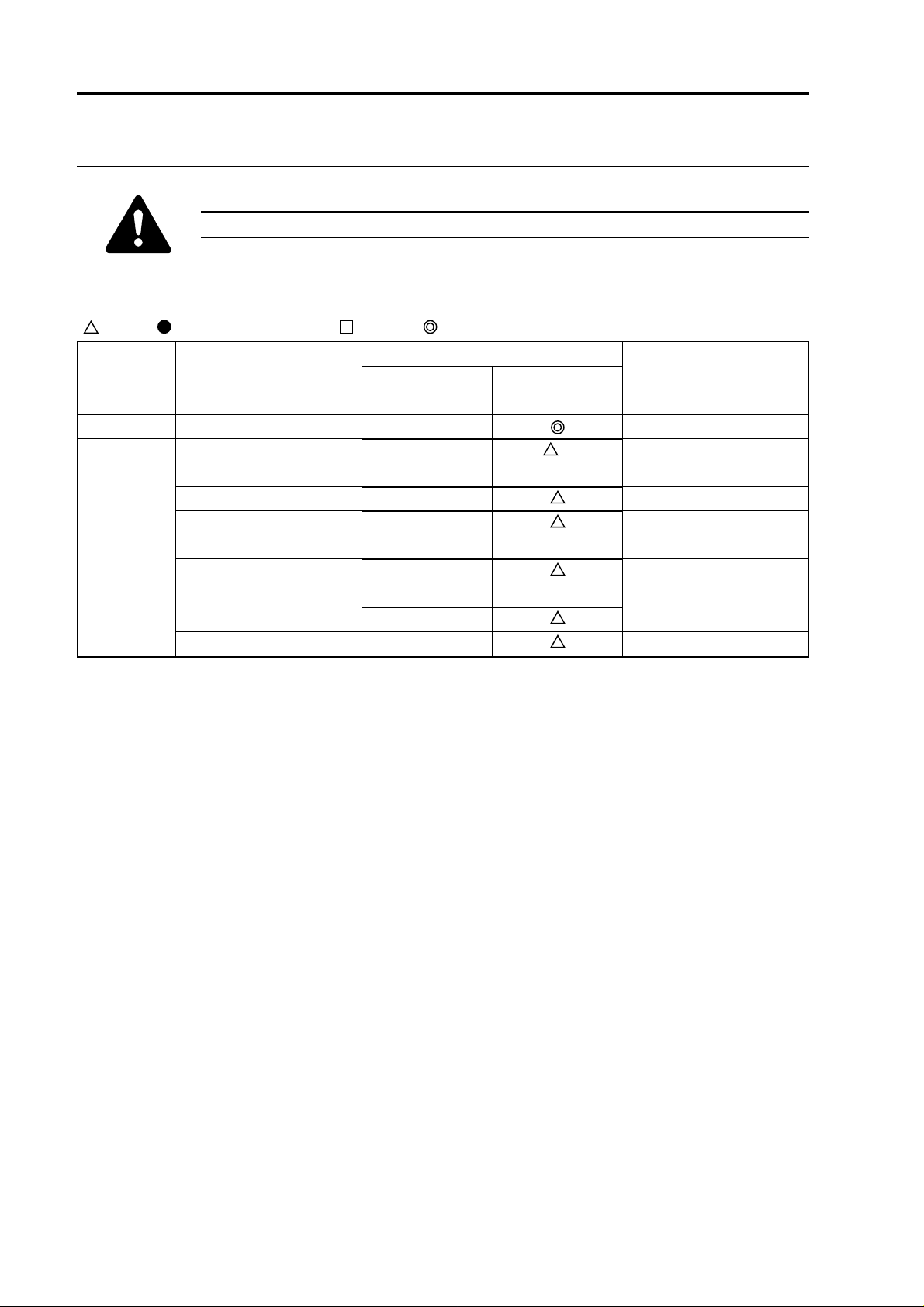
4 Scheduled Servicing Char t
Do not use solvents or oils not indicated herein.
4.1 Reader Unit
: Clean : Replace ×: Lubricate : Adjust : Inspect
Maintenance intervals
Unit
Scanner
Optical unit
Scanner cable
Scanner rail
Copyboard glass
No. 1 through No. 3
mirror
Original illumination
reflecting plate
Original size sensor
Lens
Part
Upon
installation
every 120,000
×
Remarks
Silicone oil
(S20; FY9-6011)
T01-401-01
1-6
CHAPTER 1 MAINTENANCE AND INSPECTION
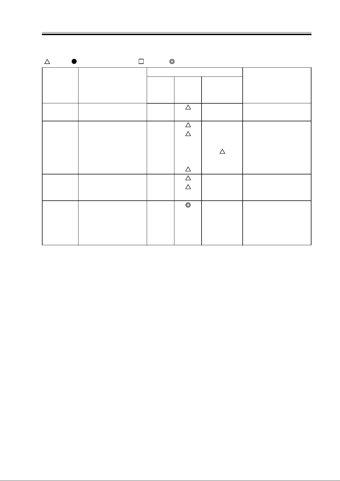
4.2 Printer Unit
: Clean : Replace ×: Lubricate : Adjust : Inspect
Maintenance intervals
Unit
Laser optical unit
Pickup/
feeding assembly
Developing
assembly
Waste toner
collection
assembly
Folding mirror
Feeding assembly base
Fixing inlet guide, upper/lower
Pre-registration (paper
lint)
Transfer guide
Developing member
Base (developing assembly)
Waste toner case
Part
Upon installation
every
120,000
Upon replacement of drum
cartridge
Remarks
Use special tool.
Inspect/remove.
(Remove the contents
and clean with alcohol.
Replace the bottle if
necessary.)
1-7
CHAPTER 1 MAINTENANCE AND INSPECTION
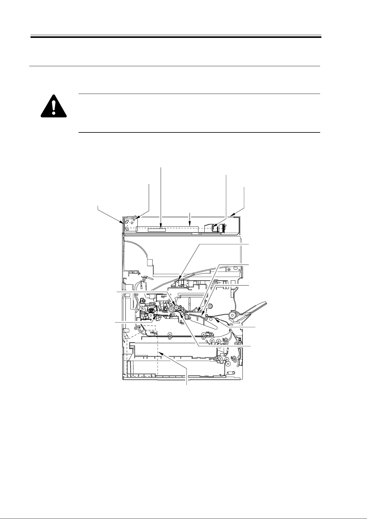
5 Points to Note for Scheduled Servicing
Unless otherwise indicated, use lint-free paper and alcohol.
• If you used solvent, check to make sure that the solvent has dried before
mounting the component back into the machine.
• Unless otherwise specified, do not use a moist cloth for cleaning.
• Provide scheduled servicing at the specified intervals.
Original size sensor
Lens
Cleaning (blower brush)
Copyboard glass
Reflecting shade
Cleaning (blower brush)
No. 1 through No. 3 mirrors
Cleaning (blower brush)
Cleaning (blower brush)
Scanner rail
Lubricating
Scanner cable
Check
Cleaning
Developing assembly bottom
Cleaning
Inlet guide (upper/lower)
Cleaning (solvent)
Bending mirror
Cleaning (special tool)
Developing assembly base
Dry wiping
Feeding assembly base
Cleaning
Pre-registration guide
Cleaning (paper lint)
Transfer guide
Cleaning
Waste toner case
Checking, disposing
(Remove waste toner, and then clean the
toner case, Replace the toner case, if any.)
1-8
F01-500-01
CHAPTER 1 MAINTENANCE AND INSPECTION
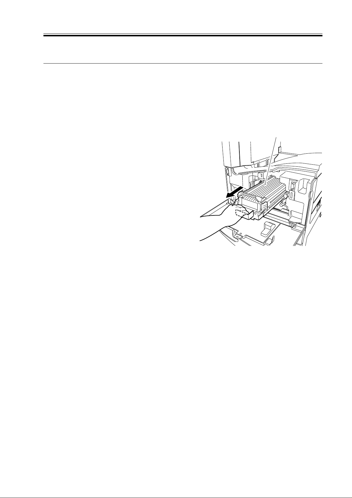
6 Cleaning the Bottom of the Developing Assembly
If the bottom of the developing assembly is not cleaned thoroughly, the residual toner can
soil the back and the leading edge or left/right edges of prints. If soiling is noted, clean also
the transfer guide and the static eliminator at the same time as the bottom of the developing
assembly.
6.1 Cleaning the Bottom of the Developing Assembly
1) Open the front door.
2) Slide out the developing assembly [1].
3) Dry wipe the bottom of the developing
assembly.
4) Slide in the developing assembly.
5) Close the front door.
[1]
F01-601-01
1-9

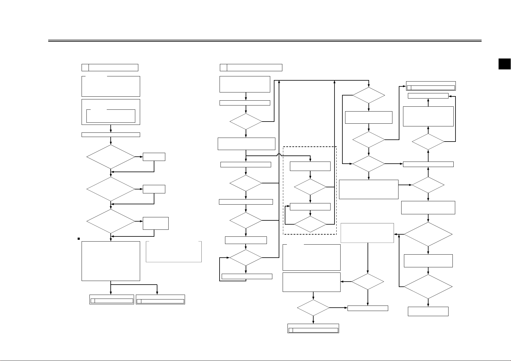
CHAPTER 2 IMAGE ADJUSTMENT BASIC PROCEDURE
CHAPTER 2 IMAGE ADJUSTMENT BASIC PROCEDURE
1
Making Initial Checks
Requirements:
1. Use paper fresh out of package.
(Moist paper will not allow correct
evaluation of images.)
2. Use paper with the highest degree of
"whiteness," of all available papers.
3. Use A3 paper (11x17), if possible.
Execute 'roller clean' in user mode
('adjust/clean').
Reference:
The following will be cleaned:
[1]Primary charging roller
[2]Transfer charging roller
Clean the separation static eliminator.
Is the setting of
'exposure recalibration'
under 'adjust/clean' in user
mode the middle
setting?
YES
Is '5' indicated for
ADJUST>DENS>DENS-ADJ
in user mode?
YES
Does the five
items on the right in
service mode match the settings
indicated on the
service label?
Output Condition
F value=5
Using the NA3 Test Chart, make 2 copies
in the following:
[1] Te xt mode
Reference: At optimum density, the copy
Generate 2 test prints each of the following in
COPIER>TEST>PG:
[1] TYPE4 (blank)
[2] TYPE5 (halftone)
[3] TYPE6 (solid black)
YES
image should barely show
gray scale No. 0.
If the copy image has a fault,
Go to Go to
2 Checking the Scanner Side.
NO
Set it to the
middle setting.
NO
Set it to '5'.
NO
Enter the settings
indicated on the
service label.
In service mode COPIER>ADJUST,
1. AE>AE-TBL
2. DEVELOP>DE-DC
3. DEVELOP>DE-OFST
4. HV-PRI>P-DC
5. HV-PRI>OFST1-DC
If the test print has a fault,
3 Checking the Printer Side (1/3).
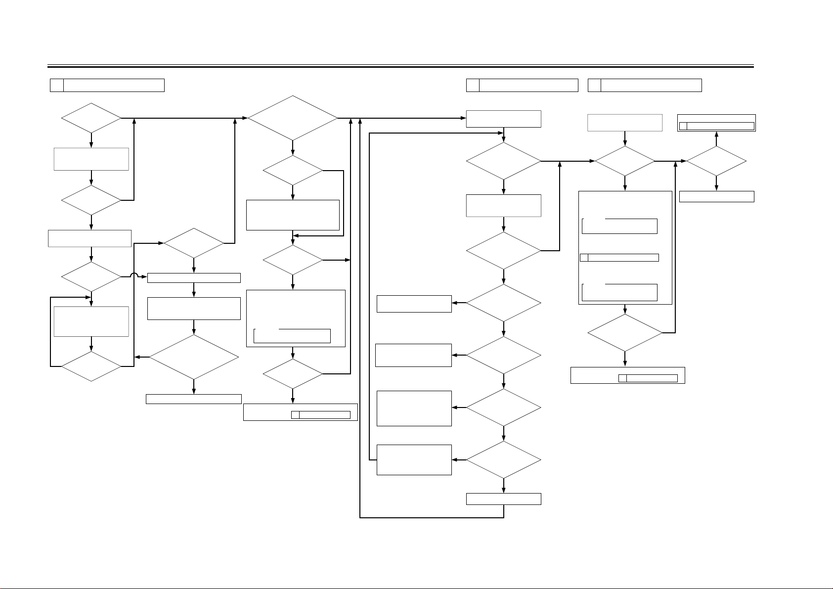
2 Checking the Scanner Side
Check/clean the following:
[1] Mirrors [2] Lens
[3]
Standard white plate
[5] Scanning lamp [6]
Make a copy in text mode.
Execute the following in service mode:
COPIER>FUNCTION>CCD>CCD-ADJ.
Change the shading position. (Note 1)
Clean the copyboard glass.
(white plate position)
Change the shading position.
Note 1: In units of 8s, increase or decrease
[4]
Copyboard glass
Reflecting plate
Is there a
vertical line in the
image?
YES
Make a copy in text mode.
Is there a
vertical line in
the image?
YES
Is there a
vertical line in
the image?
YES
Is there a
vertical line in
the image?
YES
the setting of FUNCTION>CCD
>SHDG-POS. Then, execute
FUNCTION>CCD>SH-PS-ST to see
that 'OK!' is indicated.
NO
NO
NO
NO
If a line occurs only
when the ADF is used,
Make a copy in text mode.
Is there a
vertical line in
the image?
YES
Clean the original reading
face of the ADF.
Is there a
YES
vertical line in
the image?
Reference:
Varying the setting of DENS-ADJ
affects the density of all following
copying modes:
• Auto
• Te xt
• Te xt/photo
• Photo (print photo/film photo)
Vary the setting in service mode:
COPIER>ADJUST>DENS>DENS-ADJ.
•
If the image is dark, decrease the setting.
•
If the image is light, increase the setting.
Is the copy
image density
normal?
NO
Go to
3 Checking the Printer Side (1/3).
NO
NO
YES
Is the white
NO
background of the
copy foggy?
YES
Execute shading in service mode:
FUNCTION>CCD>CCD-ADJ.
Is the image foggy?
NO
Is the density
of the copy image
normal?
NO
Vary the setting in service mode:
COPIER>ADJUST>DENS>DENS-ADJ.
• If the image is dark, decrease the setting.
• If the image is light, increase the setting.
Execute the following in service mode:
COPIER>FUNCTION>DENS.
1. WHITE-ME
2. PD-DENS
3. PD-ME
Is the copy
NO
image density in text
mode normal?
YES
End.
YES
YES
Go to
5 Checking the Printer Side (3/3).
End.
Vary the setting in service mode:
COPIER>ADJUST>AE-AE-TBL.
• If the image is dark, decrease
the setting.
• If the image is light, increase
the setting.
NO
Is the copy
density normal?
Make a copy in AE mode.
YES
Is the copy
image density
normal?
NO
Set '5' to the following in service mode:
COPIER>ADJUST>DENS>DENS-ADJ.
Is the setting of the
NO
following in service mode
485 µA or higher:
DISPLAY>HV-STS>
PRIMARY?
YES
Replace the drum unit;
then, execute the following in
service mode: COPIER>
FUNCTION>DPC>D-GAMMA.
NO
Is the setting of
the following in service mode
485 µA or higher:
DISPLAY>HV-STS>
PRIMARY?
YES
Replace the composite
power supply PCB.
2
YES
2-1
CHAPTER 2 IMAGE ADJUSTMENT BASIC PROCEDURE
3 Checking the Printer Side (1/3) 4 Checking the Printer Side (2/3) 5 Checking the Printer Side (3/3)
Is there a
vertical line in
the image?
YES
Clean the following:
[1] Laser mirror
[2] No. 1 mirror
Is there a
vertical line in
the image?
YES
Check the surface of the
developing sleeve by the naked eye.
Is there a
vertical line on the
surface of the
sleeve?
YES
Generate 10 test prints of the
following in service mode:
COPIER>TEST>PG.
TYPE6 (solid black)
Is there a
YES
line on the surface
of the sleeve?
NO
NO
Is there ea
vertical line in the
YES
NO
NO
NO
Replace the drum unit.
Execute the following service mode:
COPIER>FUNCTION>DPC>D-GAMMA.
(initialization)
Is the setting of the
following in service mode 485 µA:
DISPLAY>HV-STS>
PRIMARY?
YES
Replace the composite power supply PCB.
image?
Is the image of TYPE6
(solid black) on test prints correct in
density and free
of fuzziness?
NO
Is the image fuzzy?
YES
Check the following,
and correct any fault:
[1] Feeding assembly for locking
[2] Transfer charging roller electrode
NO
Is the image
density appropriate?
NO
Adjust the setting of the following in
service mode:
COPIER>ADJUST>DEVELOP>DE-DC.
• If the image is light, decrease the setting.
• If the image is dark, increase the setting.
Caution:
Be sure to vary the setting in
equal amounts.
Is the image
density appropriate?
NO
Replace the developing assembly, and make image
adjustments under
1 Making Initial Checks.
NO
YES
YES
YES
Replace the pre-exposure
lamp unit.
Lock it securely. If the locking
mechanism has a fault, replace it.
Generate 10 test prints (TYPE6);
then, if the coating of toner on
the developing sleeve is uneven,
replace the developing assembly.
Check the image density by
generating test prints (TYPE5).
Is there an
appreciable difference
in density between left
and right of the
image?
YES
Clean the following:
[1] Laser mirror:
[2] No. 1 mirror
Is there a difference
in density between left and
right of the image?
YES
Are both rear and
NO
front of the pre-exposure
lamp ON?
YES
Is the developing
NO
assembly securely locked
in place?
YES
Is the coating of toner
YES
on the developing
sleeve uneven?
NO
Check the image density by
generating test prints (TYPE4).
NO NO
Are the printouts
foggy?
YES
Increase the setting of the following in
service mode:
COPIER>ADJUST>DEVELOP>DE-DC.
Caution:
Be sure to vary the setting in
equal amounts.
NO
However, if the setting has already been
changed under
3 Checking the Printer Side (1/3),
decrease the following in service mode:
COPIER>ADJUST>HV-PRI>P-DC.
Caution:
Be sure to vary the setting in
equal amounts.
Is the image density
of the tense prints (TYPE6)
appropriate?
NO
Replace the developing assembly, and make image
adjustments under
1 Making Initial Checks.
Go to
2 Checking the Scanner Side.
YES
Is there a fault in
the copy image?
NO
YES
End.
2-2
Lock the feeding assembly
(transfer charging roller)
securely; if the locking
mechanism is faulty, replace the
transfer charging roller unit.
Is the
feeding assembly
NO
(transfer charging roller) locked
securely in place?
YES
Replace the laser scanner unit.
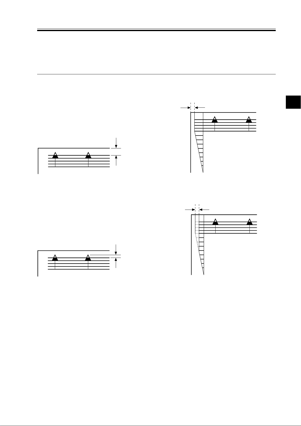
CHAPTER 3 STANDARDS AND ADJUSTMENTS
CHAPTER 3 STANDARDS AND ADJUSTMENTS
1 Image Adjustments
1.1 Standards of Image Position
The image margin/non-image width of a print made in Direct must be as follows:
2.5±1.5mm
0
2
2.5±1.5mm
4
6
8
10
F03-101-01 Image Leading Edge Margin F03-101-02 Left/Right Image Margin
2.5±1.5mm<2.5±2.0mm>
0
2.5±1.5mm
2
4
3
F03-101-03 Leading Edge Non-Image
Width
6
8
10
F03-101-04 Left Non-Image Width
< >: when the DADF-H1 picks up an
original
(in stream readig mode).
3-1

CHAPTER 3 STANDARDS AND ADJUSTMENTS
1.2 Checking the Image Position
Make prints using the following as the source of paper (10 prints each), and check to see
that the image margin and the non-image width are as indicated:
• Each cassette
• Manual feed tray
• Duplex feeding unit
• Side paper deck
If not as indicated, adjust the image position in the following order:
1. Adjusting the left/right image margin (registration)
2. Adjusting the image leading edge margin (registration)
3. Adjusting the left/right non-image width (CCD read start position)
4. Leading edge non-image width (scanner image leading edge position)
3-2
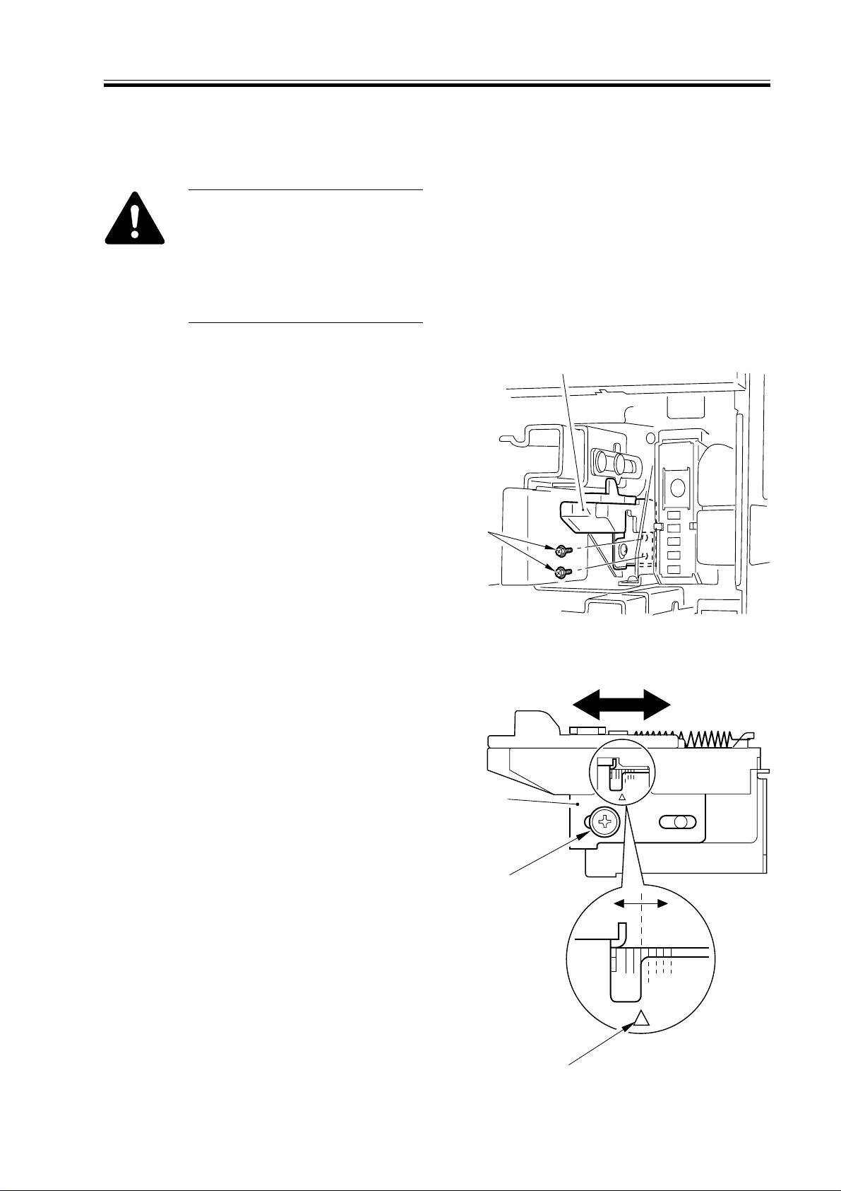
CHAPTER 3 STANDARDS AND ADJUSTMENTS
[1]
[2]
[2]
[1]
[3]
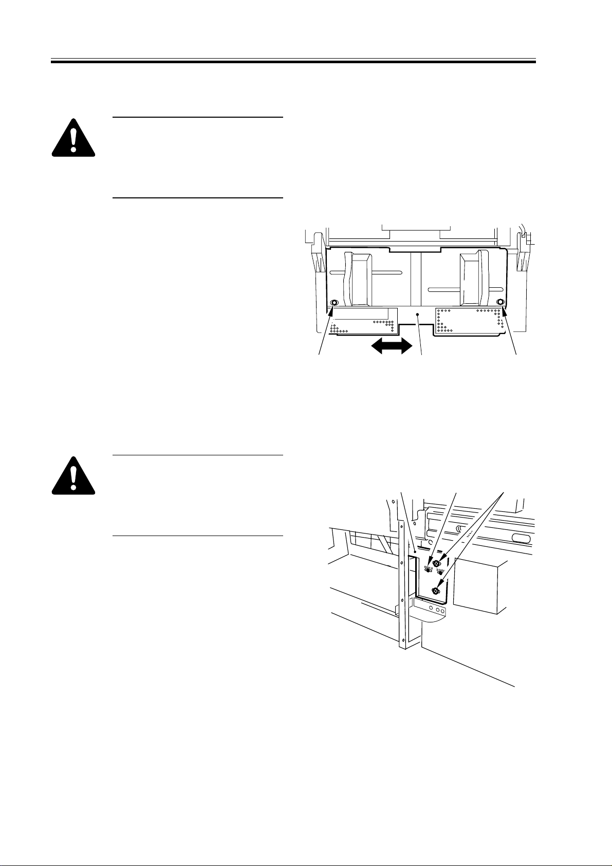
1.3 Adjusting Left/Right lamge Margin
1.3.1 Adjusting the Registration for the Cassette Rear Front
Try the following service mode
first; if not corrected, perform
the adjustments that follow:
COPIER>FUNCTION>MISCP>CI-ADJ-Y/C2-ADJ-Y/C3ADJ-Y/C4-ADJ-Y
1) Remove the cassette.
2) Remove the two screws [1], and detach
the horizontal registration base assembly [2].
F03-103-01
3) Loosen the screw [1], and adjust the
horizontal registration plate [2].
When making adjustments, try to match
the arrow [3] against the index (each
graduation being about 1 mm).
F03-103-02
3-3
CHAPTER 3 STANDARDS AND ADJUSTMENTS
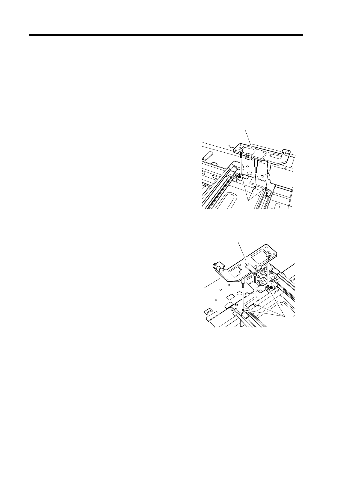
1.3.2 Adjusting the Registration for the Multifeeder Rear Front
Try the following service mode
first; if not corrected, perform
the adjustments that follow:
COPIER>FUNCTION>MISCP>MF-ADJ
1) Open the multifeeder tray.
2) Loosen the two screws [1], and move
the side guide plate unit [2] back and
forth to adjust.
1.3.3
Adjusting the Registration for the Deck
Try the following service mode
first; if not corrected, perform
the adjustments that follow:
COPIER>FUNCTION>MISCP>DK-ADJ-Y
1) Slide out the compartment.
2) Using the two screws [2], change the
position of the latch plate [1] of the
deck open solenoid (SL2D) found at the
left rear. (At this time, use the index [3]
on the latch plate as a reference.)
[2]
F03-103-03
[1] [3] [2]
[1][1]
3) Close the compartment, and check to
make sure that the gap of the front cover
is 3 ±1 mm.
4) If the gap is not 3 ±1 mm, adjust the
front cover.
3-4
F03-103-04
CHAPTER 3 STANDARDS AND ADJUSTMENTS
1.3.4 Duplex Feeding Unit
1) Adjust the image margin as indicated using service mode: COPIER>ADJUST>FEEDADJ>ADJ-REFE.
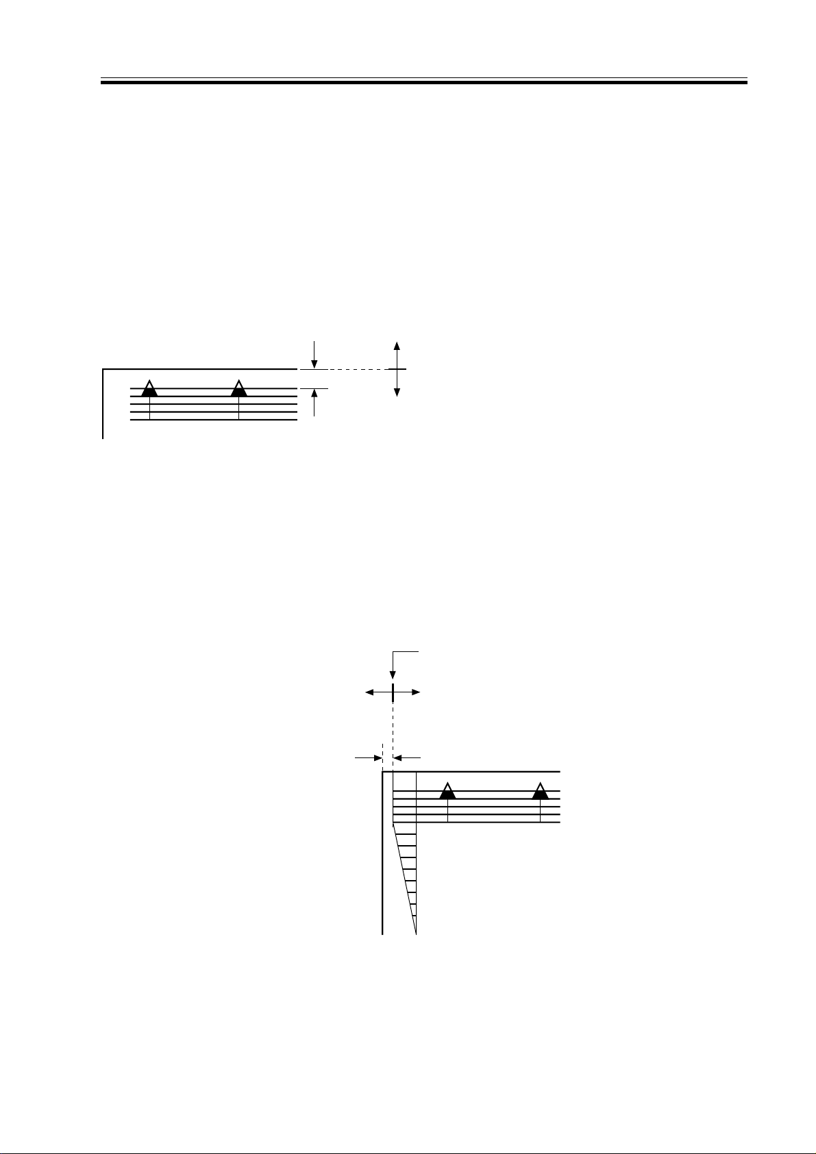
1.4 Adjusting the Image Leading Edge Margin
1) Adjust the image margin in service mode so that it is as indicated:
COPIER>ADJUST>FEED-ADJ>REGIST.
Decreasing the REGIST setting
(A decrease by ‘10’ will increase the margin by 1 mm.)
Edge of paper
Increasing the REGIST setting
(An increase by ‘10’ will decrease the margin by 1 mm.)
F03-104-01
1.5 Adjusting the Left/Right Non-Image Width
1) Adjust the non-image width in service mode so that it is as indicated:
COPIER>ADJUST>ADJ-XY>ADJ-Y.
Edge of image
Decreasing the ADJ-Y setting
(A decrease by ‘10’ will
decrease the margin by 1 mm.)
Increasing the ADJ-Y setting
(An increase by ‘10’ will increase
the non-image width by 1 mm.)
2.5mm±1.5 <2.5 ± 2.0 mm>
0
2
4
6
8
10
F03-105-01
< >: when the DADF-H1 picks up
an original (in stream readig
mode).
3-5

CHAPTER 3 STANDARDS AND ADJUSTMENTS
1.6 Adjusting the Leading Edge Non-Image Width
1) Adjust the non-image width in service mode so that it is as indicated:
COPIER>ADJUST>ADJ-XY>ADJ-X.
Decreasing the ADJ-X setting
(A decrease by '10' will decrease the width by 1 mm.)
Image leading edge
Increasing the ADJ-X setting
(An increase by '10' will increase the width by 1 mm.)
F03-106-01
2 Scanning System
2.1 After Replacing the Scanning Lamp
Run CCD auto adjustment in Service
Mode. This updates the CCD adjustment
data. Print out a new service label.
1. CCD Auto Adjust
COPIER>FUNCTION>CCD>
CCD-ADJ
2. CCD Adjustment Data
All items under
COPIER>ADJUST>CCD.
3-6
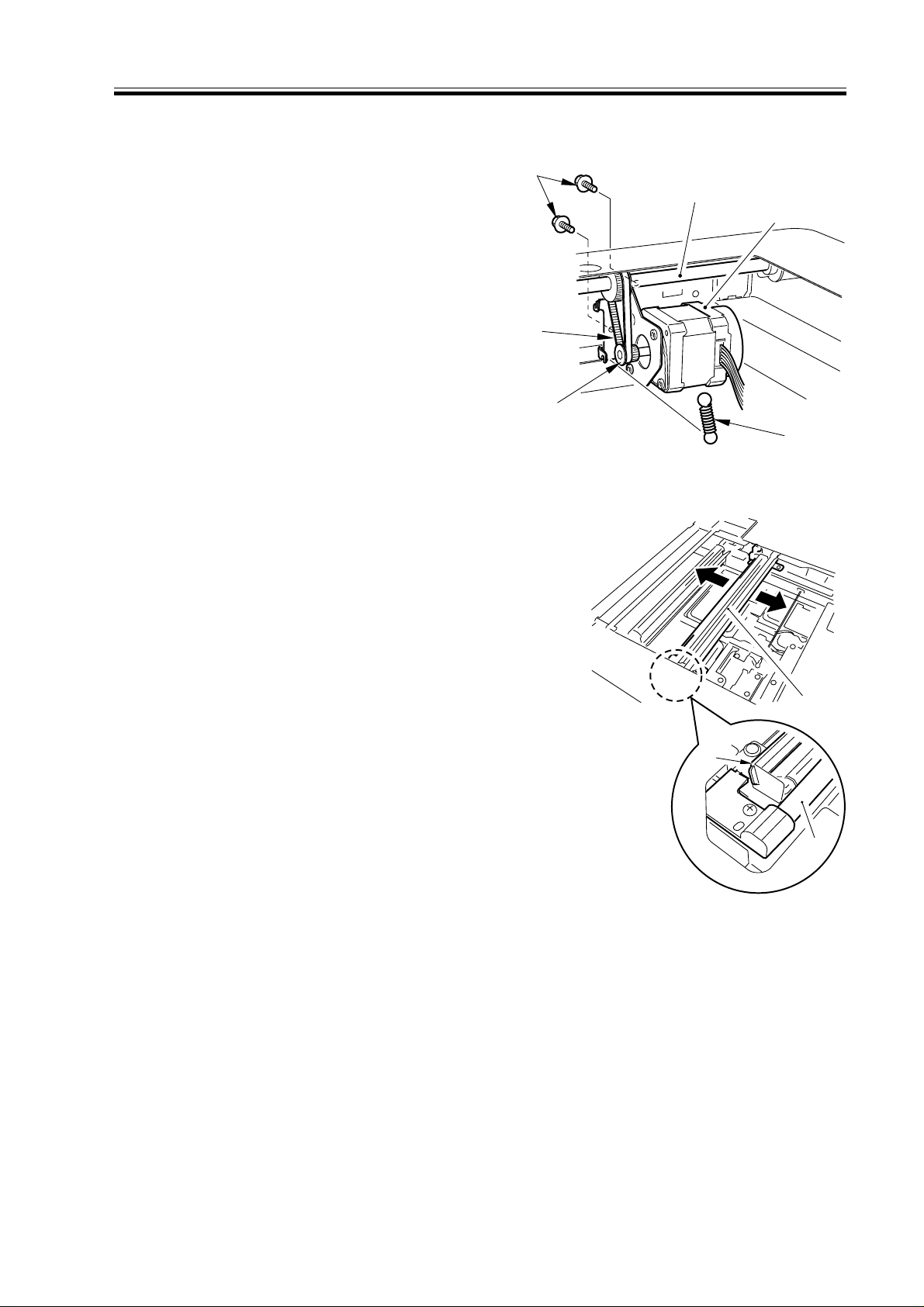
2.2 Mounting the Motor Unit
[3]
[1]
[2]
CHAPTER 3 STANDARDS AND ADJUSTMENTS
1) Engage the pulley [2] of the motor unit
[1] with the belt [3].
2) Using two screws [4], mount the motor
unit [1] temporarily.
3) Fit the spring [5] to apply tension to the
belt [3].
4) Check to make sure that the belt [3] is
vertical.
5) While taking care not to hold the scanning lamp [1] or the reflecting shade
[2], move the No. 1 mirror base [3] back
and forth two to three times to make a
check once again.
[4]
[6]
[1]
[3]
[2]
[5]
F03-202-01
6) Tighten the two screws to secure the
motor unit in place.
F03-202-02
3-7
CHAPTER 3 STANDARDS AND ADJUSTMENTS
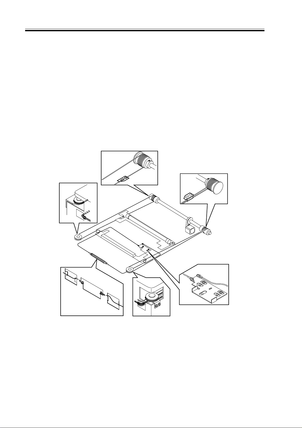
2.3 Routing the Scanner Drive Cable
Route the scanner cable as follows to the pulleys and the hook mirror base:
1) Loosen the screw on the cable fixing plate.
2) Put the ball of the cable into the hole in the drive pulley, and wind the cable firmly so
that it will not turn idly (4 runs inside, 5 runs outside); then, tape it in place. At this time,
check to make sure that the cable fixing is on the inside.
3) Engage the cable with each pulley, and temporarily fix one of its ends to the cable fixing
plate and the other to the hook on the reader frame.
4) Temporarily secure the cable fixing in place to the No. 1 mirror base. (Do not tighten the
screw fully.)
5) Fit the reader upper frame.
6) Adjust the position of the No. 1 and No. 2 mirror bases.
3-8
F02-203-01

CHAPTER 3 STANDARDS AND ADJUSTMENTS
2.4 Adjusting the Position of the No. 1/No. 2 Mirror Base
1) Set the pins of the mirror positioning
tool as indicated:
• For the Front (F marking)
[C]
[B]
[A]
(initial; FY9-3009) (set for the machine)
• For the Rear (R marking)
[C]
[B]
(initial; FY9-3009) (set for the machine)
[A]
[A]
[C]
[B]
F03-204-01
[A]
[C]
[B]
F03-204-02
3-9
CHAPTER 3 STANDARDS AND ADJUSTMENTS
2) Fit the pins of the mirror positioning
tool (front [2], rear [3]) into the holes
[1] of the rail and the No. 1/No. 2 mirror base. The No. 2 mirror base is adjusted in keeping with the back-andfroth movement of the cable fixing
plate.
Front Side (F marking)
Rear Side (R marking)
[2]
[1]
F03-204-03
[3]
3) Fix the end of the cable (which is temporarily secured on the hook of the
reader frame) in place using the spring.
4) Fully tighten the screw on the cable fixing plate.
5) Fully tighten the screw on the cable fixing so that it is secured on the No. 1
mirror base.
6) Detach the mirror positioning tool (2
pc.).
3-10
[1]
F03-204-04
 Loading...