

New Product Information
iR2200/2800/3300
Date : January 25, 2001
File No. : C-17-01-001
Confidential
Released by : Canon Inc.
OIP QA Center
OIP TS Division
This document precedes the Service Manual for the product in question and
serves as a reference, thereby providing the Sales Companies with a good
understanding of the product in advance.
Most of the contents of this document are not official and, therefore, are subject to change before the product is brought into being, making it important to
bear in mind that the descriptions are true only as of the date indicated on the
cover.
Yoshiaki Takase, General Manager
OIP QA Division
(TS001102)

New Product Information
Introduction to New Product Information
The document “New Product Information” replaces the Trainer’s Manual (TR) most of
you are familiar with, and is the result of our efforts to provide information useful to all
departments concerned in each Sales Company.
Most of the contents of this document are not official and, therefore, are subject to
change before the product is brought into being, making it important to bear in mind that
the descriptions are true only as of the date indicated on the cover.
The Service Manual for the product will have descriptions updated to reflect the changes
that may have occurred. Kindly make arrangements so that this document is properly
disposed of as soon as the Service Manual is released.
January,25, 2001
Canon Inc.
OIP QA Center
OIP QA Division

CHAPTER 1
GENERAL DESCRIPTION
COPYRIGHT
©
2001 CANON INC. 2000 2000 2000 2000 CANON iR3300/2800/2200 REV.0 JAN. 2001

CHAPTER 1 GENERAL DESCRIPTION
1 Specifications
1.1 Main Body
1.1.1 Type
Item Description
Body Desktop
Copyboard Fixed
Light source Xenon lamp
Lens Lens array
Photosensitive medium OPC drum (30-mm dia.)
T01-101-01
1.1.2 Systems
Item Description
Reproduction Indirect electrostatic
Charging AC roller
Exposure Laser
Copy density adjustment Auto or manual
Development Single-component toner projection
Pickup Auto Front cassette (2 cassettes)
Retard method (about 500 sheets of 80 g/m2 paper, about 550
sheets of 64 g/m2 paper)
Manual Multifeeder
Dual process method (about 50 sheets of 80 g/m2 paper)
Transfer Roller
Separation Static eliminator (static separation) + curvature
Cleaning Blade
Fixing SURF method (plane heater and fixing film)
COPYRIGHT
©
T01-101-02
2001 CANON INC. 2000 2000 2000 2000 CANON iR3300/2800/2200 REV.0 JAN. 2001
1-1

CHAPTER 1 GENERAL DESCRIPTION
1.1.3 Functions
Item Description
Resolution Reading 600dpi×600dpi
Copying 1200dpi×600dpi
Printer output 2400dpi×600dpi
Original type Sheet, book 3-D object (2 kg max.)
Maximum original size A3/279.4×431.8mm (11"×17")
Reproduction ratio Direct (1:1), Reduce I (1:0.250), Reduce II (1:0.500),
Reduce III (1:0.611), Reduce IV (1:0.707), Reduce III (1:1.414),
Enlarge IV (1:2.000), Enlarge V (1:4.000), Enlarge VI (1:8.000),
Zoom (1:0.250 to 8.000 in 1% increments)
Wait time 10 sec or less (at 20°C)
First copy time 5.4 sec (book mode, cassette 1, Direct, A4/LTR, text mode)
Continuous copying 999 copies max.
Copy size
Cassette A/B A3 max., A5 (vertical feed) min.
Inch 279.4×431.8 mm (11"×17") max., STMT (vertical feed) min.
Manual feed AB A3 max., postcard (vertical feed) min.
Inch 279.4×431.8 mm (11"×17") max., STMT (vertical feed) min.
Cassette 1/2 • Plain paper (64 to 80 g/m2):A3, B4, A4, B5, A5R, A4R, B5R,
279.4×431.8mm (11"×17"), LGL, LTR, LTRR, STMT, STMTR
• Tracing paper (SM-1):A3, B4, A4, B5, A4R, B5R
• Colored paper (Canon-recommended):B4, A4, A4R
Multifeeder • Plain paper (64 to 80 g/m2):A3, B4, A4, B5, A5R, A4R, B5R,
279.4×431.8mm (11"×17"), LGL, LTR, LTRR, STMT, STMTR
• Tracing paper (SM-1, GSN-75):A3, B4, A4, B5, A4R, B5R
• Transparency (Canon-recommended):A4, A4R, LTR, LTRR
• Colored paper (Canon-recommended):B4, A4, A4R
• Postcard: Jpn (vertical feed), double-card, 4-sheet card
• Label sheet (Canon-recommended):B4, A4, A4R, LTR, LTRR
• Thick paper (90 to 128 g/m2):A3, B4, A4, B5, A4R, B5R, LTR,
LTRR
• Envelope
T01-101-03
1-2
COPYRIGHT
©
2001 CANON INC. 2000 2000 2000 2000 CANON iR3300/2800/2200 REV.0 JAN. 2001

CHAPTER 1 GENERAL DESCRIPTION
Item Description
Single-sided copying mode • Plain paper (64 to 80 g/m2):A3, B4, A4, B5, A5R, A4R, B5R,
279.4×431.5mm (11"×17"), LGL, LTR, LTRR, STMT, STMTR
• Tracing paper (SM-1, GSN-75):A3, B4, A4, B5, A4R, B5R
• Transparency (Canon-recommended)A4, A4R, LTR, LTRR
• Colored paper (Canon-recommended):B4, A4, A4R
• Postcard: Jpn postcard (vertical feed), double-card, 4-sheet card
• Label sheet (Canon-recommended):B4, A4, A4R, LTR, LTRR
• Thick paper (90 to 128 g/m2):A3, B4, A4, B5, A4R, B5R, LTR,
LTRR
• Envelope
Double-sided copying mode (automatic)
• Plain paper (64 to 80 g/m2):A3, B4, A4, B5, A5R, A4R, B5R,
279.4×431.8mm (11"×17"), LGL, LTR, LTRR, STMT, STMTR
• Colored paper (Canon-recommended):B4, A4, A4R
• Thick paper (90 to 128 g/m2):A3, B4, A4, B5, A4R, B5R, LTR,
LTRR
Double-sided copying mode (multifeeder)
• Plain paper (64 to 80 g/m2):A3, B4, A4, B5, A5R, A4R, B5R,
279.4×431.8mm (11"×17"), LGL, LTR, LTRR, STMT, STMTR
• Colored paper (Canon-recommended):B4, A4, A4R
• Postcard: Jpn (vertical feed), double-card, 4-sheet card
• Thick paper (90 to 128 g/m2):A3, B4, A4, B5, A4R, B5R, LTR,
LTRR
COPYRIGHT
©
T01-101-04
2001 CANON INC. 2000 2000 2000 2000 CANON iR3300/2800/2200 REV.0 JAN. 2001
1-3

CHAPTER 1 GENERAL DESCRIPTION
Item Description
Cassette Claw None
Capacity 55 mm deep (approx.; about 500 sheets of 80 g/m2 paper)
Hard disk 6.4GB (*1)
Non-image width Leading edge Direct, Enlarge/Reduce:4.0±1.5/-1.0mm <4.5±1.8mm>*2
Trailing edge Direct, Enlarge/Reduce:2.0±1.5mm <2.0±1.8mm>*2
Left/right (1st side) Direct, Enlarge/Reduce:2.5±1.5mm <2.5±2.0mm>*2
Auto clear Yes (2 min standard; may be changed in 1-min increments
between 0 and 9 min)
Auto power-off Yes
Low-power mode Yes (15 min standard; may be changed in user mode to
10, 15, 20, 30, 40, 50, 60, 90 min, 2, 3, or 4 hr)
Sleep mode Yes (60 min standard; may be changed in user mode to
10, 15, 20, 30, 40, 50, 60, 90 min, 2, 3, or 4 hr)
Yes (-10% standard; may be changed in user mode to -
10%, -25%, -50%, or no return (0%))
Accessory • DADF-H1
• Copyboard Cover Type-E
• Copyboard-D1
• Copy Tray-F1
• Saddle Finisher-G1
• Puncher Unit-G1
• Finisher-J1
• Inner 2-Way Tray-A1
• Side Paper Deck-L1
• 2-cassette Pedestal-W1
• Options Power Supply-B1 (required for SF, PD)
• Cassette Heater Kit-16N
• Control Card-IV
• Network LIPS Printer Kit-A1 (100V model only)
• Network Multi-PDL Printer Kit-A1 (120/230V model
only)
*1:The HDD that comes with the machine and the HDD that is made available as a service part may
have different memory sizes; however, the area of the HDD used by the machine will be the same,
and either may be used without a problem.
*2:The values within parentheses indicate when the DADF is used.
T01-101-05
The above specifications are subject to change for product improvement.
1-4
COPYRIGHT
©
2001 CANON INC. 2000 2000 2000 2000 CANON iR3300/2800/2200 REV.0 JAN. 2001

CHAPTER 1 GENERAL DESCRIPTION
1.1.4 Others
Item Description
Operating environment Temperature range 15° to 30°C
Humidity range 5 to 80%
Atmospheric pressure 810.6 to 1013.3 hpa (0.8 to 1.0 atm)
Power supply E201
LQHxxxxx
100V (50/60Hz) LQJxxxxx
NRFxxxxx
120V (50/60Hz) NRGxxxxx
PKMxxxxx
220V/60Hz PKKxxxxx
230V (50/60Hz) PKLxxxxx
QCWxxxxx
RBZxxxxx
SCKxxxxx
TBZxxxxx
UFMxxxxx
Power consumption Maximum E201: 1.5 kW or less
Standby E201: 282 W (approx.; reference only)
Continuous E201: 995 W (approx.; reference only)
Noise Sound power level (Impulse mode)
Copying E201: 66 dB or less, E202: 71 dB or less
Standby E201: 40 dB or less, E202: 50 dB or less
Ozone 0.01 ppm or less avg., 0.02 ppm or less max.
Dimensions (mm) (iP-Lite) 565 (W) × 678 (D) × 1020 (H)
(iP-Std) 565 (W) × 678 (D) × 1040 (H)
Weight 80 kg (approx.)
Consumables Copy paper Keep wrapped to protect against humidity.
Toner Keep away from direct sunshine, and keep at
40°C/85% or less.
T01-101-06
COPYRIGHT
©
2001 CANON INC. 2000 2000 2000 2000 CANON iR3300/2800/2200 REV.0 JAN. 2001
1-5

CHAPTER 1 GENERAL DESCRIPTION
Reproduction mode Side Paper size copies /min (1-to-N)
E201 E202
Direct A3 (297×420mm) A3 - 16
A4 (210×297mm) A5 - A5 (149×210mm) A4 22 33
B4 (257×364mm) B4 - 14
B5 (182×257mm) B5 - 28
A4R (297×210mm) A4R - B5R (257×182mm) B5R - A5R (210×149mm) A5R - -
Reduce II
(50.0%) A3 → A5R A5R - III
(61.1%) A3 → B5R B5R - IV
(70.7%) B4 → B5R B5R - V A3 → A4R A4R - (81.6%) B4 → A4R A4R - VI B5R → A5R A5R - (86.5%) A4 → B5 B5 - -
A3 → B4 B4 - -
Enlarge IV
(200.0%) A5R → A3 A3 - III
(141.4%) A4R → A3 A3 - II B5R → B4 B4 - (122.4%) A4R → B4 B4 - I A5 → B5 B5 - (115.4%) B4 → A3 A3 - -
B5 → A4 A4 - -
Delivery by copier, Auto paper select ON, Auto density, Non-sort, Deck/Cassette
T01-101-07 Copying Speeds (copier only)
1-6
COPYRIGHT
©
2001 CANON INC. 2000 2000 2000 2000 CANON iR3300/2800/2200 REV.0 JAN. 2001

CHAPTER 1 GENERAL DESCRIPTION
Reproduction mode Size (1toN)
E201 E202
Direct 279.4×431.8mm 279.4×431.8mm - 16
(11"×17") (11"×17")
LTR LTR 22 33
LGL LGL - 14
LTRR LTRR - -
STMTR STMTR - -
Reduce II 279.4×431.8mm STMTR - -
(50.0%) (11"×17") → STMTR
III 279.4×431.8mm LTRR - (64.7%) (11"×17") → LTRR
IV 279.4×431.8mm LGL - (73.3%) (11"×17") → LGL
V LGL → LT RR L TRR - (78.6%)
Enlarge IV STMTR* → 279.4×431.8mm - -
(200.0%) 279.4×431.8mm (11"×17")
(11"×17")
III LTRR → 279.4×431.8mm - (129.4%) 279.4×431.8mm (11"×17")
(11"×17")
II LGL → 279.4×431.8mm - (121.4%) 279.4×431.8mm (11"×17")
(11"×17") copies/min
Paper size
*STMTR cannot be used as an original.
Delivery by copier, Auto paper select ON, Auto density, Non-sort, Deck/Cassette
T01-101-08 Copying Speeds (copier only)
The above specifications are subject to change for product improvement.
COPYRIGHT
©
2001 CANON INC. 2000 2000 2000 2000 CANON iR3300/2800/2200 REV.0 JAN. 2001
1-7

CHAPTER 1 GENERAL DESCRIPTION
1.2 Side Paper Deck-L1
Item Description
Pickup method Retard
Paper accommodation Front loading
Paper type (horizontal feed only) Plain paper (65 to 80 g/m2): A4, B5, LT R
Colored paper (Canon-recommended): A4
Capacity 2,500 sheets (approx.; 80 g/m2 paper)
Serial number A4 type:XCQxxxxx LTR type: XCRxxxxx
Paper size switch By size guide plate/in service mode
Dimensions 324 (W) × 591 (D) × 432 (H) mm
Weight 30 kg (approx.)
Power supply None (DC power supplied by accessories power supply of
host machine)
Operating conditions Same as host machine
T01-200-01
The above specifications are subject to change for product improvement.
1-8
COPYRIGHT
©
2001 CANON INC. 2000 2000 2000 2000 CANON iR3300/2800/2200 REV.0 JAN. 2001
2 Names of Parts
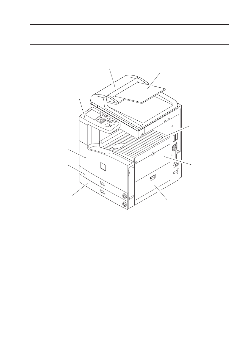
2.1 External View
CHAPTER 1 GENERAL DESCRIPTION
[4]
[5]
[1] ADF
[2] Original tray
[3] Control panel
[4] Front cover
[5] Cassette 1
[6] Cassette 2
[7] Delivery tray
[8] Multifeeder
[6]
[3]
[1]
[2]
[7]
[8]
[9]
[9] Right lower cover
[10] DIMM ROM replacement cover
[11] Network card slot
[12] Parallel connector
[13] Extension board slot
[14] Main power switch
[15] Cassette heater switch
COPYRIGHT
©
F01-201-01 External View 1
2001 CANON INC. 2000 2000 2000 2000 CANON iR3300/2800/2200 REV.0 JAN. 2001
1-9
CHAPTER 1 GENERAL DESCRIPTION
[1]
[2]
[3]
[4]
[6]
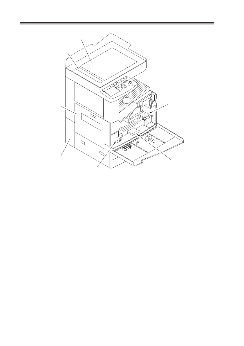
[1] Copyboard glass
[2] DADF reading glass
[3] Left cover
[4] Left lower rear cover (waste toner
case cover)
F01-201-02 External View 2
[5]
[7]
[5] Developing assembly releasing
lever
[6] Feeding assembly releasing lever
[7] Duplex feeding assembly releas-
ing lever
1-10
COPYRIGHT
©
2001 CANON INC. 2000 2000 2000 2000 CANON iR3300/2800/2200 REV.0 JAN. 2001
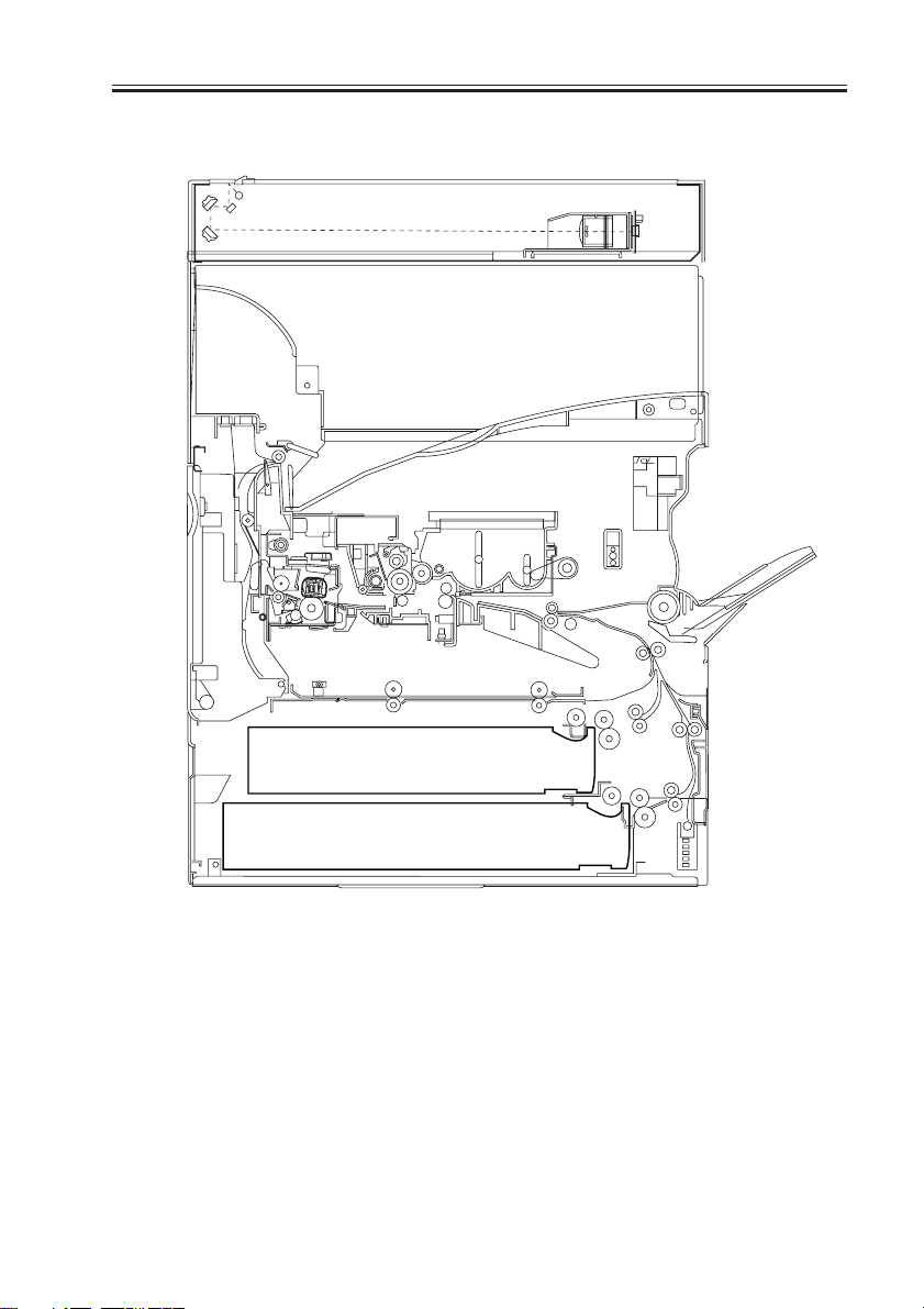
2.2 Cross Section
CHAPTER 1 GENERAL DESCRIPTION
COPYRIGHT
©
F01-202-01 Cross Section
2001 CANON INC. 2000 2000 2000 2000 CANON iR3300/2800/2200 REV.0 JAN. 2001
1-11

CHAPTER 1 GENERAL DESCRIPTION
[1] DADF reading glass
[2] No. 1 mirror
[3] Scanning lamp
[4] Copyboard glass
[5] Fixing assembly
[6] Feeding assembly
[7] Laser mirror 3
[8] Laser mirror 2
[9] Laser mirror 1
[10] Drum cleaner assembly
[11] Primary charging assembly
[12] Photosensitive drum
[13] Laser mirror 4
[14] CCD unit
[15] Laser unit
[16] Dust-proofing glass
[17] Developing cylinder
[18] Pre-transfer charging assembly
[19] Multifeeder pickup roller
[20] Multifeeder separation roller
[21] Registration roller
[22] Transfer roller
[23] Static eliminator
[24] Cassette 1 pickup roller
[25] Cassette 1 feeding roller
[26] Cassette 1 separation roller
[27] Cassette 2 pickup roller
[28] Cassette 2 feeding roller
[29] Cassette 2 separation roller
[30] Cassette 1
[31] Cassette 2
[32] Lower fixing roller
[33] Inside delivery roller
[34] Outside delivery roller
[35] Upper fixing roller
[36] No. 3 mirror
[37] No. 2 mirror
T01-202-01
1-12
COPYRIGHT
©
2001 CANON INC. 2000 2000 2000 2000 CANON iR3300/2800/2200 REV.0 JAN. 2001
CHAPTER 1 GENERAL DESCRIPTION
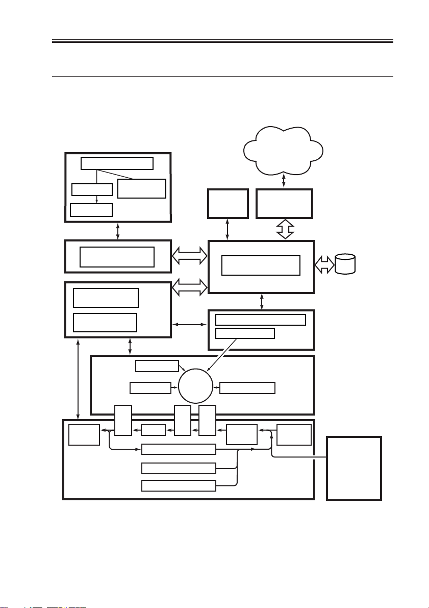
3. System Configuration
3.1 Functional Construction
The machine may be broadly divided into the following six functional blocks:
Various
networks or public
Original
telephone
network
Optical path
CCD PCB
Reader controller
DC controller
PCB
DC power
supply PCB
Delivery
tray
Original
illumination
Original
Exposure Block
PCB
Control
Block
Charging
Cleaning
Feeding
Fixing
Photo-
sensitive
drum
Separation
Lower feeding assembly
Cassette 1
Cassette 2
Control
panel
Main controller PCB
Image Processing Block
Laser driver PCB
Laser scanner
Development
Image Formation Block
Pickup
Transfer
control
Pickup/Feeding Block
Various
accessory
boards
Exposure Block
Laser
Multi-
feeder
HDD
Side paper
deck
(accessory)
COPYRIGHT
©
F01-301-01
2001 CANON INC. 2000 2000 2000 2000 CANON iR3300/2800/2200 REV.0 JAN. 2001
1-13
CHAPTER 1 GENERAL DESCRIPTION
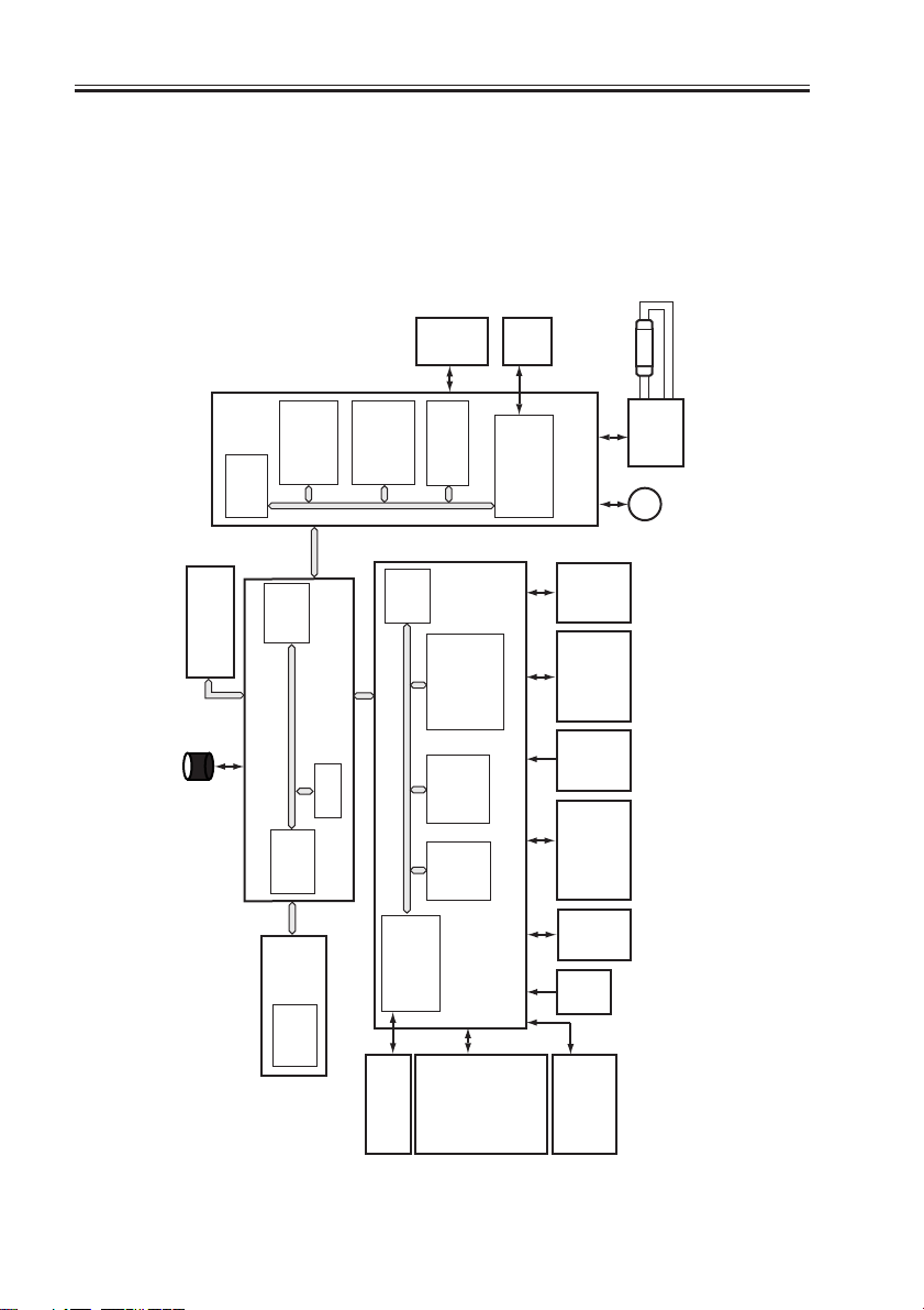
3.2 Outline of the Electrical Circuitry
3.2.1 Construction of the Electrical Circuit
The major electrical mechanisms of the machine are controlled by the following PCBs:
[1] Man controller PCB; controls the system as a whole, processes images
[2] DC controller PCB; controls the printer unit, controls the finisher communication
[3] Reader controller PCB; controls the reader unit, controls the DADF communication
IC5025
boards
Accessory
drive
(HDD)
Hard disk
(CPU)
IC1010
(DIMM-
Control
(ROM)
IC5008
IC5016
(CPU)
ROM)
panel
PCB
IC5009
Main controller PCB
(RAM)
CCD
(RAM)
IC5027
IC125
(CPU)
IC104,105
DIMM/
IC121
IC120
unication 2)
(IPC comm-
PCB
(EEPROM)
IC109,110
ROM
IC122
ADF
IC5021
(IPC comm-
IC127,130
(EEPROM)
(IC117)
(RAM)
DC controller PCB
unication 2)
Reader
controller PCB
Main
power
supply
power
supply
Composite
PCB
Drum
sensor
power
supply
Accessories
PCB
drive
Laser
BD
PCB
LA2
PCB
PCB
PCB
Inverter
M3
PCB
motor
Scanner
1-14
(CPU)
IC6501
COPYRIGHT
PCB
• Finisher
(accessory)
DC loads
• Clutch
• Solenoid
• Motor
• Sensor
• Fan
• Etc.
Pickup
F01-302-01
©
2001 CANON INC. 2000 2000 2000 2000 CANON iR3300/2800/2200 REV.0 JAN. 2001
CHAPTER 1 GENERAL DESCRIPTION
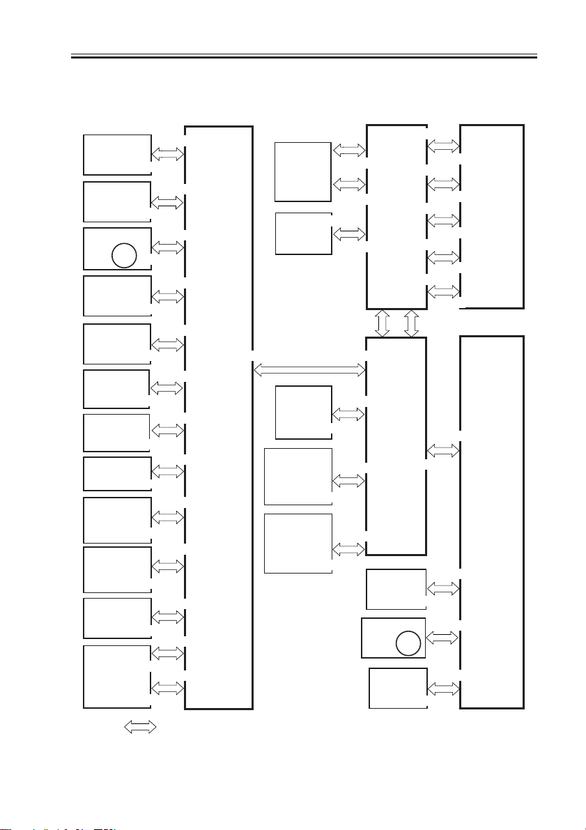
3.3 Inputs to and Outputs from the Major PCBs
3.3.1 Wiring Diagram of the Major PCBs
Potential
control
PCB
Duplex
driver
J2302
PCB
Laser scanner
motor
M15
J2511
Laser drive
PCB
J2501
BD PCB
DC power
supply PCB
J2701
J4003
HVT PCB
J4502
Environment
sensor PCB
Cassette 3
paper level
detection
Cassette 4
paper level
detection
AC driver
PCB
PCB
PCB
Motor
driver
PCB
J806
J810
J2052
J2101
J2108
J3
J8492
J103
J107
J116
J121
J120
J101
J102
J113
J113
J113
J102
J104
J105
DC
controller
PCB
LCD panel
(LCD)
Inverter
PCB
Hard disk
Control
Card-IV
(accessory)
Copy Data
Controller
(accessory)
J956
J1551
J1532
J1530
J6503
J6507
J6506
J6505
J1012
J1015J122
J1017
J1060
J1022
Control
panel
CPU PCB
Controller
assembly
CCD/AP
PCB
Scanner
motor
Inverter
PCB
M3
J6604
J6509
J6504
J6501
J6508
J6801
J1018
J1014
J6002
J5101
J6502
J6601
J6602
J6603
J6605
J5004
J5003
J5011
J5007
Keypad
PCB
Reader
controller
PCB
Note: The in the diagram indicates connection between PCBs, NOT the flow of signals.
F01-303-01
COPYRIGHT
©
2001 CANON INC. 2000 2000 2000 2000 CANON iR3300/2800/2200 REV.0 JAN. 2001
1-15
CHAPTER 1 GENERAL DESCRIPTION
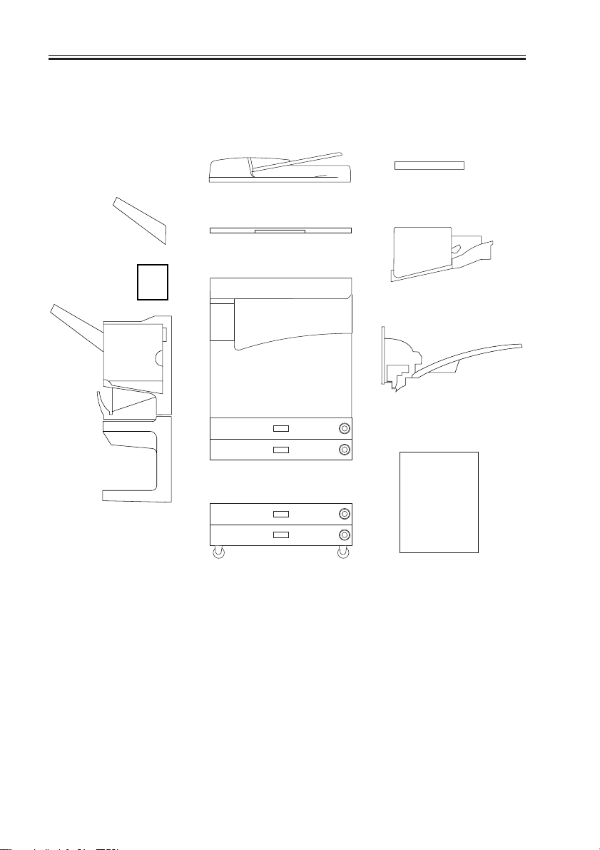
3.4 Configuration with Accessories
3.4.1 Accessories for Original/Paper Feeding
[5]
[4]
[6]
[1]
[2]
[10]
[3]
[7]
[8]
[9]
[1] DADF-H1
[2] Copyboard Cover Type-E
[3] Copyboard-D1
[4] Copy Tray-F1
[5] Saddle Finisher-G1
[6] Puncher Unit-E1
1-16
COPYRIGHT
[7] Finisher-J1
[8] Inner 2-Way Tray-A1
[9] Side Paper Deck-L1
[10] 2-Cassette Pedestal-W1
[11] Options Power supply-N1
(required when [5] or [9] is used)
F01-304-01
©
2001 CANON INC. 2000 2000 2000 2000 CANON iR3300/2800/2200 REV.0 JAN. 2001
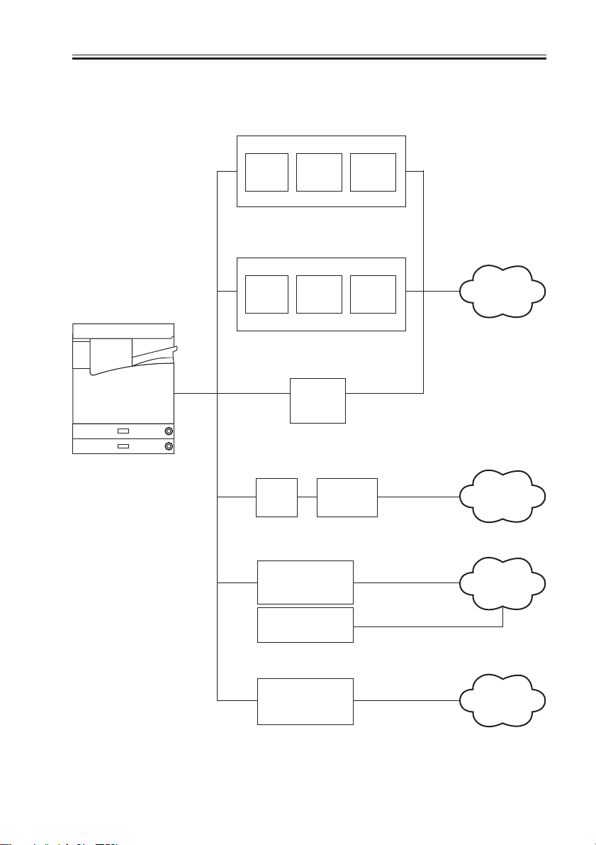
3.4.2 Accessory Boards
CHAPTER 1 GENERAL DESCRIPTION
LIPS Printer Kit-B1
LPS
PCB
Network Multi-PDL
Printer Kit-B1
RIP1
PCB
Relay PCB
Relay
PCB
Relay
PCB
Network
Network
PCB
Relay
PCB
Super G3 FAX
Board-J1
Token Ring
TokenRing
PCB
Network
PCB
Network
PCB
Ethernet
network
TokenRing
network
Public
telephone
network
COPYRIGHT
©
Multiport Kit-B1
G4 FAX Board-B1
F01-304-02
2001 CANON INC. 2000 2000 2000 2000 CANON iR3300/2800/2200 REV.0 JAN. 2001
ISDN network
1-17

CHAPTER 2
ORIGINAL EXPOSURE SYSTEM
COPYRIGHT
©
2001 CANON INC. 2000 2000 2000 2000 CANON iR3300/2800/2200 REV.0 JAN. 2001

CHAPTER 2 ORIGINAL EXPOSURE SYSTEM
1. Outline of Operations
1.1 Outline
The original exposure system has the following major functions:
Item Description
Original illumination Xenon tube
Original scanning In Book mode: by moving scanner
With ADF in use: by fixed No. 1 mirror base at stream reading po-
sition
scanner position detection Scanner HP sensor (PS400)
Reproduction ratio (zoom) [1] Copyboard Mode (25% to 800%)
Main scanning direction: image processing by controller assembly
Sub scanning direction: for a ratio of 50% or higher, changing
scanning speed of No. 1 mirror; for a
ratio of lower than 50% and 400% or
higher, chaining scanning speed and im-
age processing
[2] ADF Mode (25% to 400%)
Main scanning direction: image processing by controller assembly
Sub scanning direction: for a ratio of 50% or higher, changing
original feeding speed; for a ratio of
lower than 50% and 200% or higher,
Scanner drive control No. 1/No. 2 mirror base: control by stepping motor (M400)
Lens Lens array, fixed type
Scanning lamp control [1] Control of activation by inverter circuit
[2] Control for error detection
Original size detection [1] In Book Mode
Sub scanning direction: by reflection type sensor
Main scanning direction: by CCD
[2] With ADF in Use
By ADF
COPYRIGHT
©
2001 CANON INC. 2000 2000 2000 2000 CANON iR3300/2800/2200 REV.0 JAN. 2001
2-1
CHAPTER 2 ORIGINAL EXPOSURE SYSTEM
1.2 Changing the Reproduction Ratio (Zoom)
[1] In Copyboard Mode
If for a reproduction ratio of 25% to 800%, the speed of the scanner is changed.
[2] With ADF in Use
If for a reproduction ratio of 25% to 400%, the speed of the movement of the original is
changed.
1.2.1 Changing the Reproduction Ratio in Main Scanning Direction
For scanning direction, reading is always at 100% in both copyboard and ADF modes; the
ratio is changed in the course of data processing in the main controller assembly.
To reduce, data units are skipped.
To enlarge, data units are repeated.
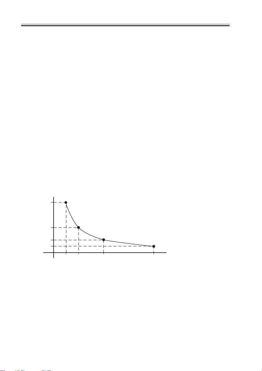
1.2.2 Changing the Reproduction Ratio in Sub Scanning Direction
For sub scanning direction, the speed of the scanner/movement of the original is changed.
However, for a reduction between 25% and 49% and enlargement between 401% and 800%,
data processing in the main controller assembly is also used in combination.
[1] For enlargement, the speed of the mirror/original is reduced from that used in Direct:
e.g., at 200%, the speed is 1/2 of the speed used in Direct.
[2] For reduction between 50% and 99%, the speed of the mirror/original is increased;
e.g., at 50%, the speed is twice as high as that used in Direct.
(speed ratio)
2
1
1/2
1/4
50%
(reproduction ratio)
400%200%100%
F02-102-01
[3] For a reduction between 25% and 49%, image data read at 50% to 98% is subjected to
skipping (1/2) in the main controller assembly.
[4] For an enlargement between 401% and 800%, image data read at 200% to 400% is sub-
jected to repeating (doubling) in the main controller assembly.
2-2
COPYRIGHT
©
2001 CANON INC. 2000 2000 2000 2000 CANON iR3300/2800/2200 REV.0 JAN. 2001

CHAPTER 3
LASER EXPOSURE SYSTEM
COPYRIGHT
©
2001 CANON INC. 2000 2000 2000 2000 CANON iR3300/2800/2200 REV.0 JAN. 2001

CHAPTER 3 LASER EXPOSURE SYSTEM
1 Outline of Operations
1.1 Outline
Part 2>Chapter 4>1.1 “Outline of Laser Exposure”
The reader controller PCB serves to read image signals from the CCD and send image
signals to the main controller assembly. The video signals from the main controller assembly are converted by the DC controller PCB into laser drive signals, and are turned into laser
intensity signals to suit signal levels by the laser driver PCB.
The laser intensity signals are used to cause the laser unit to generate a laser beam, which
is directed to the photosensitive drum for the formation of latent static images.
The laser beam is also used for blank exposure to create non-image areas.
Item Description
Laser intensity control Laser power auto control (APC control)
Laser scanning By semiconductor laser
Synchronization control Main scanning direction: control by BD signal
Sub scanning direction: control by image leading edge signal
Laser scanner motor control Constant speed rotation control
T03-101-01
COPYRIGHT
©
2001 CANON INC. 2000 2000 2000 2000 CANON iR3300/2800/2200 REV.0 JAN. 2001
3-1
CHAPTER 3 LASER EXPOSURE SYSTEM
F03-101-01 shows the major components for the laser exposure system; the machine’s la-
ser scanning is performed by means of a 6-facet polygon mirror and a single-beam laser unit:
Laser unit
BD mirror
Photosensitive drum
Cylindrical lens
Polygon mirror
(6-faceted)
Laser scanner motor
Collimating lens
BD PCB
Laser mirror
F03-101-01 External View
Component Description
Laser semiconductor Visible laser light (about 6760 nm), single-beam
Laser scanner motor (M10) DC brush-less motor, constant speed control
Polygon mirror 6-faceted
BD mirror/BD PCB Laser beam detection
Laser driver PCB Laser activation control
DC controller PCB Laser scanner motor rotation control
3-2
T03-101-02 List of Components
COPYRIGHT
©
2001 CANON INC. 2000 2000 2000 2000 CANON iR3300/2800/2200 REV.0 JAN. 2001
CHAPTER 3 LASER EXPOSURE SYSTEM
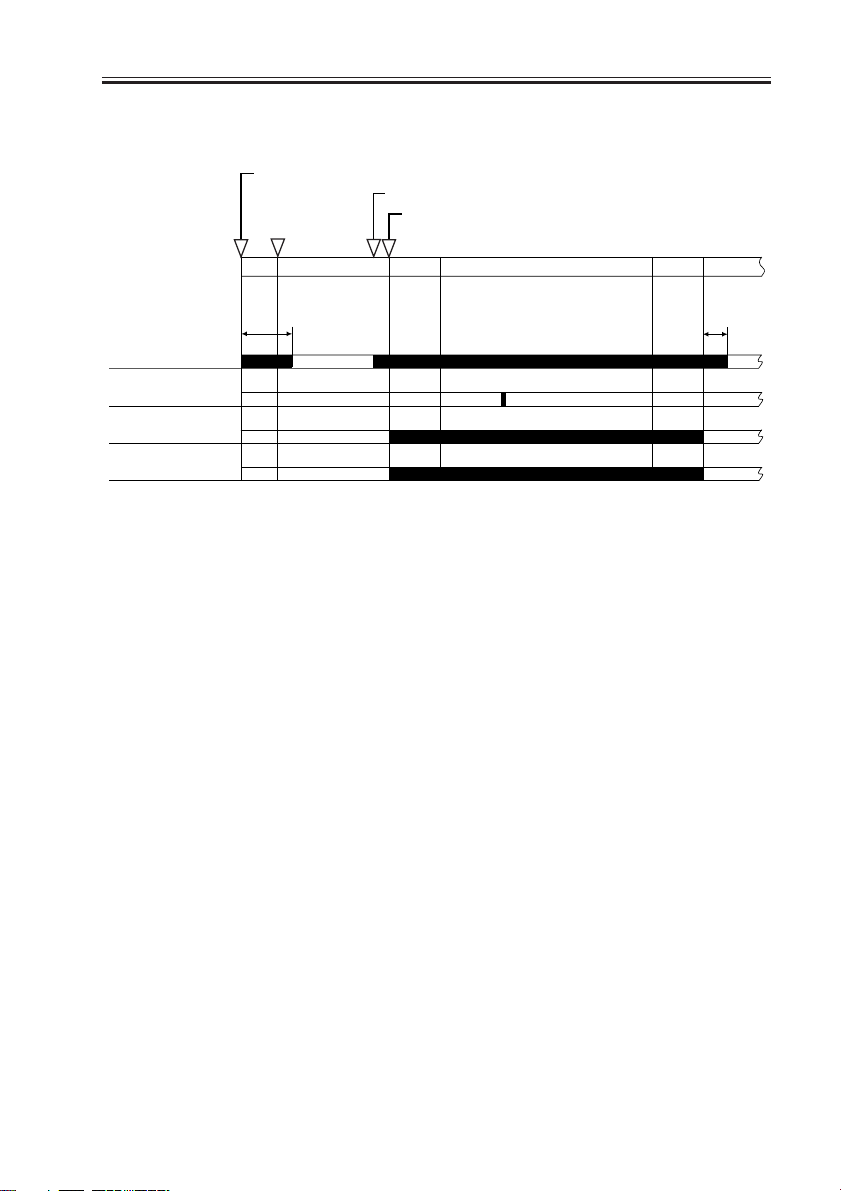
1.2 Sequence of Operations (laser exposure system)
Main power switch ON/sleep mode OFF
Original set/ADF opened
180˚C
Start key ON
Laser scanner
motor
Image leading
edge signal
Laser
BD signal
AINTR
8 sec
*: If silent mode (in user mode) is selected, the motor stops after a
specific period of time.
STBY
INTR
PRINT
LSTR
F03-102-01 Basic Sequence of Operations
STBY
*
COPYRIGHT
©
2001 CANON INC. 2000 2000 2000 2000 CANON iR3300/2800/2200 REV.0 JAN. 2001
3-3
CHAPTER 3 LASER EXPOSURE SYSTEM
2 Generating Sync Signals
2.1 Outline
Part 2>Chapter 4>2 “Generating BD Signals”
The BD signal used to synchronize the video signals in laser scanning direction is generated by the BD PCB with reference to the laser beam reflected by the BD mirror mounted in
the path of the laser beam.
The edge of paper re-picked in double-sided mode is detected by the horizontal registration sensor to measure the displacement to the rear/front. Based on the measurement, the
timing of laser activation is changed with reference to the BD signal so that the image will
be placed at a specific position on the paper without fail.
Laser unit
Polygon mirror (6-faceted)
BD mirror
3-4
Photosensitive drum
F03-201-01 Construction of the Control System
COPYRIGHT
©
2001 CANON INC. 2000 2000 2000 2000 CANON iR3300/2800/2200 REV.0 JAN. 2001
BD PCB
CHAPTER 3 LASER EXPOSURE SYSTEM
2.2 Flow of Sync signals
[1] The BD signal goes ‘0’ when laser light is detected.
[2] The phase is matched with the phase of the printer, and a sync signal is generated.
[3] Based on the printer sync signal, image data is read from the image memory.
[4] Video signal
[5] The 2-pixel parallel signal is converted into a single-pixel serial signal.
[6] The laser drive signal is used to drive the laser unit to suit the video signal.
J3129 J312
GND
BD PCB
Laser driver
PCB
4
3
2
1
J500
GND
[6]
[1]
5V
J307
B11
B12
B13
B14
Sync signal
generation
[2]
Parallel/
serial
conversion
[5]
A18
J122
J122
[3]
[4]
J1015
A18
Memory
control
J1015
COPYRIGHT
©
DC controller
PCB
Controller assembly
F03-202-01 Flow of Signals
E100
Indicates that the BD signal cannot be detected within a specific period of
time after the laser has been turned on.
2001 CANON INC. 2000 2000 2000 2000 CANON iR3300/2800/2200 REV.0 JAN. 2001
3-5

CHAPTER 3 LASER EXPOSURE SYSTEM
3 Laser Driver Circuit
3.1 Controlling the Laser Unit
The laser driver circuit is used to drive the semiconductor laser according to the laser
drive signal from the DC controller PCB.
The laser driver circuit performs the following:
1. Turning on/off the laser.
2. Controlling the light intensity of the laser (APC control).
The signals have the following meanings and functions:
[1] Laser drive signal; used to drive the semiconductor laser.
[2] Sample laser activation signal; used to turn on the laser for intensity sampling (the result
is used for activation for imaging).
[3] Laser enable signal; goes ‘0’ when the laser is ready after the Start key is pressed.
[4] Image leading edge signal; used to start laser writing when paper reaches the image
leading edge sensor (PSS12) mounted in front of the photosensitive drum.
[5] Used to monitor the laser intensity when the laser is turned on for sampling, and feeds
back the level appropriate to the intensity to the laser driver circuit.
[6] Used to control the output so that the feedback level and the reference level from the DC
controller will be identical.
[7] Laser intensity reference signal; used as the laser activation reference level determined
by the DC controller.
[8] Horizontal registration paper detection signal; used to adjust the image position by
changing the timing of laser activation with reference to the result of detection of the
edge of paper re-picked in double-sided mode by the horizontal registration sensor
(PS11).
3-6
COPYRIGHT
©
2001 CANON INC. 2000 2000 2000 2000 CANON iR3300/2800/2200 REV.0 JAN. 2001

CHAPTER 3 LASER EXPOSURE SYSTEM
DC controller
PCB
REF.
J307
1
2
3
4
1
2
3
4
5
J310
GND
DATA(+) [1]
DATA(-) [1]
GND
GND
+5V
DAOUT [7]
S/H [2]
LDE [3]
J500
4
3
3
2
2
1
1
J501
5
4
3
2
1
Laser
drive
circuit
Laser assembly
[6]
Laser
Intensity
monitor [5]
Laser driver PCB
Laser unit
J312
INT_TOPO_PD [4]
A14
Image leading edge
(PS12)
J304
A8
Y_REG_PD [8]
sensor
Horizontal registration
paper sensor
(PS11)
F03-301-01
1. The laser power of the laser unit is adjusted when the unit is shipped out
of the factory.
COPYRIGHT
©
2001 CANON INC. 2000 2000 2000 2000 CANON iR3300/2800/2200 REV.0 JAN. 2001
3-7

CHAPTER 3 LASER EXPOSURE SYSTEM
DISPLAY>DPOT>LLMT-P
Use it to indicate the laser power voltage control for printer (PDL) images.
DISPLAY>DPOT>LLMT
Use it to indicate the laser power voltage control for the copier.
DISPLAY>DPOT>LPOWER-P
Use it to indicate the result of potential control for the laser intensity during
output of printer (PDL) images.
DISPLAY>DPOT>LPOWER-C
Use it to indicate the result of potential control for laser intensity during
output of copier images.
ADJUST>LASER>PVE-OFST
Use it to adjust the position of laser illumination.
ADJUST>LASER>LA-OFF
Use it to adjust the timing of laser trailing edge de-activation for non-default size papers.
3-8
COPYRIGHT
©
2001 CANON INC. 2000 2000 2000 2000 CANON iR3300/2800/2200 REV.0 JAN. 2001

CHAPTER 3 LASER EXPOSURE SYSTEM
4 Controlling the Laser Scanner Motor
4.1 Outline
Part 2> Chapter 4> 4.1 “Outline”
The following items are related to laser scanner motor control:
[1] Laser scanner motor drive signal; when ‘1’, the laser scanner motor goes ON (turning
on/off the motor).
[2] Laser scanner motor ready signal; when ‘0’, the laser scanner motor rotates at a specific
speed (constant speed rotation control).
DC controller
PCB
Main power
supply PCB
[1]
[2]
J3128
4
3
2
1
Speed
control
circuit
Reference
pulse
generation
circuit
Motor
driver
B10
J312
B9
GND
+24V
2
1
J204
F03-401-01 Functional Block Diagram
E110
Indicates the presence of an error in the laser scanner motor.
M10
Laser scanner
motor
COPYRIGHT
©
2001 CANON INC. 2000 2000 2000 2000 CANON iR3300/2800/2200 REV.0 JAN. 2001
3-9

CHAPTER 3 LASER EXPOSURE SYSTEM
5.1 Laser Scanner Assembly
5.1.1 Removing the Laser Unit
1) Remove the delivery tray. (See p. ?.)
2) Open the harness guide [1], and disconnect the two connectors [2].
3) Disconnect the connector [3] of the BD
PCB, and disconnect the two connectors
[4] of the laser PCB.
4) Remove the two springs [1] and the two
stepped screws [2] on the left side, and
remove the two screws [3] (w/washer)
on the right; then, detach the laser unit.
[3]
[2]
[1]
[1]
F03-501-01
[2]
F03-501-02
[1]
[4]
[3]
3-10
When mounting, be sure to do
so while butting it against the
two leaf springs [1] at the front.
COPYRIGHT
©
2001 CANON INC. 2000 2000 2000 2000 CANON iR3300/2800/2200 REV.0 JAN. 2001
[1]
[1]
F03-501-03

CHAPTER 3 LASER EXPOSURE SYSTEM
When installing the Finisher-J1
(Chapter 10), be sure to attach
the protective sheet [2] along
the line marking [1] on the laser
unit.
[1]
[2]
F03-501-04
COPYRIGHT
©
2001 CANON INC. 2000 2000 2000 2000 CANON iR3300/2800/2200 REV.0 JAN. 2001
3-11

CHAPTER 4
IMAGE FORMATION SYSTEM
COPYRIGHT
©
2001 CANON INC. 2000 2000 2000 2000 CANON iR3300/2800/2200 REV.0 JAN. 2001

CHAPTER 4 IMAGE FORMATION SYSTEM
1 Outline of Processes
1.1 Outline
T04-101-01 shows the functions of and the methods used in the image formation system:
Item Description
Photosensitive drum OPC (30-mm dia.)
drum cleaning cleaning blade
Developing assembly Developing cylinder (20-mm dia.)
Development method:dry, 1-component, toner projection
Toner:magnetic, negative
Pre-exposure (LAMP2) Fuse lamp (8 pc.)
ON/OFF control (activated in sync with main motor)
Drum sensor (U701) Primary charging roller DC bias corrected to temperature around
photosensitive drum
Environment sensor (S3) Primary charging roller AC bias corrected to suit humidity reading
Primary charging roller auto Pad push-on type
cleaning
Primary charging roller bias DC constant voltage control (-500 to -850 V)
control AC constant current control (2000 to 2300 µA; about 1800 Hz)
Developing bias control DC constant voltage control (0 to -650 V)
AC constant voltage control (810 Vp-p; about 1800 Hz)
Transfer charging roller bias Transfer bias:DC constant current control (switching
control among +15 µA, +10 µA, +7 µA) + DC constant voltage
control (up to 7 kVmax)
Cleaning bias: DC constant voltage control (-2.6 kV)
Transfer guide bias control DC constant voltage (-600 v)
Separation static eliminating DC constant voltage (switching between -2.3 KV and -3.0 KV)
bias control
COPYRIGHT
©
T04-101-01
2001 CANON INC. 2000 2000 2000 2000 CANON iR3300/2800/2200 REV.0 JAN. 2001
4-1

CHAPTER 4 IMAGE FORMATION SYSTEM
F04-101-01 shows the major components of the image formation system:
Primary charging roller
Pre-exposure lamp
Developing assembly
Cleaner unit
Photosensitive
drum
Separation static eliminator
Transfer guide
Transfer charging roller
F04-101-01
4-2
COPYRIGHT
©
2001 CANON INC. 2000 2000 2000 2000 CANON iR3300/2800/2200 REV.0 JAN. 2001

CHAPTER 4 IMAGE FORMATION SYSTEM
1.2 Basic Sequence of Operations (image formation system)
• 1 Original, 2 Prints
Control panel
Main power
supply switch ON
AINRT
Main motor
Pre-exposure
lamp
Laser activation
Primary charging
bias
Primary charging
bias
Transfer charging
bias
Image leading
edge sensor
Developing bias
Developing bias
Transfer guide
bias
Separation static
eliminating bias
power switch
ON
STBY
SLEEP
[2]
Start key ON
INRT
[3][1] [3]
[2]
PRINT LSTR
[2]
STBY
COPYRIGHT
©
[1] transfer charging reference bias
[2] transfer charging cleaning bias
[3] transfer sheet-to-sheet interval bias
F04-102-01
2001 CANON INC. 2000 2000 2000 2000 CANON iR3300/2800/2200 REV.0 JAN. 2001
4-3

CHAPTER 4 IMAGE FORMATION SYSTEM
2 Controlling the Primar y Charging Roller Bias
2.1 Outline
Part 2>Chapter 5>4.4 “Controlling the Primary Charging Roller Bias”
The machine’s primary charging is a direct charging method that uses a charging roller. In
addition to a DC bias, the charging roller is subjected to an AC bias to ensure stable charging.
The following items relate to the control of primary charging:
[1] Turning on/off the bias.
[2] Controlling the DC bias to a specific level of voltage.
[3] Controlling the AC bias to a specific level of current.
[4] Controlling the photosensitive drum resistance detection mechanism (APVC control).
[5] Controlling the AC bias based on the readings of the environment sensor (humidity) and
the soft counters.
[6] Controlling the DC bias based on the reading of the drum sensor (temperature).
Composite power supply PCB
+24V
signal
J135
J136
-B9
-A10
-A12
Transformer
drive signal
DC bias
output ON
signal
DC bias
output
control signal
Current level
(APVC measure ment)
PW-CPU
Voltage level
Transformer
drive signal
AC bias output
control signal
Primary DC
charging high-
voltage
transformer
(T502)
Output
control
Current
control
charging high-
voltage trans
Drive
control
Primary AC
former
Voltage
detection
Current
detection
DC bias
output
AC bias
output
Primary
charging roller
J130-4
Photosensitive
Drum sensor
(temperature)
drum
24 VDC input
Primary charging
J301
output enable
-B4
Serial communication
Print/standby mode signal
AC bias level signal
DC bias level signal
APVC measurement data
-A3
DC controller PCB
-A1
4-4
J311-A2
J302-B14
Memo
Environment
sensor
Measurement result
Measurement result
(humidity)
F04-201-01
The primary charging output enable signal is used as the AC pulse ON signal when the developing bias is being controlled.
COPYRIGHT
©
2001 CANON INC. 2000 2000 2000 2000 CANON iR3300/2800/2200 REV.0 JAN. 2001

CHAPTER 4 IMAGE FORMATION SYSTEM
2.2 Turning On/Off the Bias
The primary charging roller bias is turned on/off as follows:
2.2.1 DC Bias
[1] When the primary charging output enable signal from the DC controller PCB goes ‘0’,
the DC bias output control signal (pulse signal) is generated.
[2] The DC bias is sent to the primary charging roller.
2.2.2 AC Bias
[1] When the primary charging output enable signal from the DC controller PCB goes ‘0’,
the AC bias output control signal is generated.
[2] The AC bias is generated to the primary charging roller.
2.3 Controlling the Current Voltage/Current to a Specific Level
The output level of the DC/AC bias applied to the primary charging roller is controlled by
the DC/AC bias output control signal from the PW-CPU.
2.3.1 Controlling the DC Bias to a Specific Level
[1] The output voltage level of the DC bias is fed back to the PW-CPU, and the DC bias
output control signal is varied as needed to suit the level when driving the transformer.
[2] The DC bias is made to assume a specific voltage level.
2.3.2 Controlling the AC Bias to a Specific Current Level
[1] The output current level of the AC bias is communicated to the drive control circuit and
is compared against the reference current level; the result is used to vary the AC bias
output control signal as needed to drive the transformer.
[2] The AC bias is made to assume a specific current level.
COPYRIGHT
©
2001 CANON INC. 2000 2000 2000 2000 CANON iR3300/2800/2200 REV.0 JAN. 2001
4-5

CHAPTER 4 IMAGE FORMATION SYSTEM
2.4 Temperature Correction of the DC Bias
When the temperature inside the machine increases, the resistance of the photosensitive
drum will decrease, thereby lowering the charging characteristics. To ensure a stable potential level, the drum sensor (U701) mounted to the rear side plate is used to check the temperature inside the machine; when the temperature increases, the absolute value of the DC
bias level is increased.
-800V
-750V
Primary DC bias
(reference
value)
Low
23˚C 40˚C
Machine inside temperature
High
F04-204-01
2.5 Humidity Correction of the AC Bias
The current level of the AC bias needs to be kept on the higher side to prevent uneven
charging because of a lower changing efficiency occurring in a low-humidity environment.
The AC bias, therefore, is varied as shown in F04-205-01 to suit the readings of the environment sensor (humidity). When the resistance of the drum surface decreases because of advancing wear, the current level is decreased to facilitate the flow of current.
Counter reading: 0 to 10,000 sheets Counter reading: 10,001 or higher
2300µA
2150µA
2000µA
Primary AC bias
Low
35%
Humidity
High
F04-205-01
Low
35%
Humidity
High
4-6
COPYRIGHT
©
2001 CANON INC. 2000 2000 2000 2000 CANON iR3300/2800/2200 REV.0 JAN. 2001

CHAPTER 4 IMAGE FORMATION SYSTEM
2.6 Controlling the Detection of the Photosensitive Drum Resistance (APVC control)
The primary charging efficiency changes because of changes in the site environment (temperature, humidity), deterioration of the charging roller, and wear of the photosensitive
drum. The reference voltage is applied to the charging roller when the main power switch is
turned on, and the resulting output current level is measured for correction.
[1] When the main power switch is turned on, the reference voltage is applied to the charg-
ing roller, and the output is measured as the current level for use as feedback to the PWCPU.
[2] The photosensitive drum is charged (primary charging) using the voltage level deter-
mined by the PW-CPU.
COPYRIGHT
©
2001 CANON INC. 2000 2000 2000 2000 CANON iR3300/2800/2200 REV.0 JAN. 2001
4-7

CHAPTER 4 IMAGE FORMATION SYSTEM
2.7 Controlling the Output Mode
In continuous print mode, the outputs of both AC bias and DC bias are varied between
image areas and non-image areas to prevent stray toner in the non-image areas.
E064
Indicates the presence of a high-voltage (primary charging, transfer charging, developing) output fault.
COPIER>DISPLAY>HV-STS>PRIMARY
Use it to indicate the current level of primary charging.
COPIER>ADJUST>HV-PRI>P-DC
Use it to enter the adjustment value of the primary charging DC component
for the image area.
COPIER>ADJUST>HV-PRI>P-AC
Use it to enter the adjustment value of the primary charging AC component
for the image area.
COPIER>ADJUST>HV-PRI>AGS-GAIN
Use it to enter the gain adjustment value of the application voltage level
correction for the primary charging bias.
CCOPIER>ADJUST>HV-PRI>AGS-OFST
Use it to enter the offset adjustment value of the application voltage level
correction for the primary charging bias.
CCOPIER>ADJUST>HV-PRI>OFST1-DC
Use it to enter the adjustment value of offset 1 for the primary charging DC
component.
CCOPIER>ADJUST>HV-PRI>OFST1-AC
Use it to enter the adjustment value of offset 1 for the primary charging AC
component.
CCOPIER>ADJUST>HV-PRI>P-AC2
Use it to enter the adjustment value of primary charging AC component 2 of
the image area.
CCOPIER>ADJUST>HV-PRI>P-AC3
Use it to enter the adjustment value of primary charging AC component for
the image area.
4-8
COPYRIGHT
©
2001 CANON INC. 2000 2000 2000 2000 CANON iR3300/2800/2200 REV.0 JAN. 2001

CHAPTER 4 IMAGE FORMATION SYSTEM
3 Controlling the Transfer Charging Roller Bias
3.1 Outline
Part 2>Chapter 5>7.8.3 “Controlling the Transfer Roller”
The machine’s transfer charging is a direct charging method that uses a transfer charging
roller. A DC bias is applied to the transfer charging roller.
The following relate to the transfer charging system:
[1] Turning on/off the bias.
[2] Controlling the DC bias to a specific voltage/current level.
[3] Controlling the detection of transfer charging roller resistance (ATVC control)
[4] Controlling the output by operation mode
[5] Controlling the output by the environment sensor (humidity)
Composite power supply PCB
+24V
24 VDC input
Transfer
charging
J301
output enable
-B9
Transfer output
mode signal 4
-B8
communication
Print/standby mode signal
Transfer bias output data
ATVC measurement data
-A3
-A1
Transfer output
DC controller PCB
mode signal 1
-B5
Transfer output
mode signal 2
-B6
Transfer output
mode signal 3
-B7
signal
Serial
J135
J136
-B4
-B5
-A10
-A12
-B8
-B7
Transfer bias output
current switching signal
-B6
Transformer drive
signal
Cleaning bias output
ON signal
Voltage level
(ATVC measurement result)
Voltage
detection
Transformer drive
signal
PW-CPU
Transfer bias output
ON signal
Transfer bias
output control
signal
Drive
control
Transfer cleaning
bias high-voltage
transformer
(T506)
Transfer bias
high-voltage
transformer
(T133)
Current
level
Cleaning
Transfer
output
Current
detection
bias out
bias
Photosensitive
T133
Transfer
charging roller
Environment
(humidity)
drum
sensor
COPYRIGHT
©
Measurement resultJ302-B14
F04-301-01
2001 CANON INC. 2000 2000 2000 2000 CANON iR3300/2800/2200 REV.0 JAN. 2001
4-9

CHAPTER 4 IMAGE FORMATION SYSTEM
3.2 Turning On/Off the Bias
The transfer charging roller bias is turned on/off as follows:
[1] When the transfer charging output enable signal from the DC controller PCB goes ‘0’,
the transfer bias output signal (serial communication) is generated.
[2] The transfer bias output control signal (pulse) is generated, and the DC bias is sent to
the transfer charging roller.
3.3 Controlling the Detection of the Transfer Charging Roller
Resistance (ATVC control)
The transfer charging efficiency changes because of changes in humidity and deterioration in the transfer charging roller. The reference current is applied to the transfer charging
roller during initial multiple rotation after the main power switch is turned on, and the resulting output voltage is measured for correction.
[1] The reference current is applied to the transfer charging roller, and the output is checked
as a voltage level for use as feedback to the PW-CPU.
[2] The transfer charging mechanism operate using the voltage level determined by the PW-
CPU.
4-10
COPYRIGHT
©
2001 CANON INC. 2000 2000 2000 2000 CANON iR3300/2800/2200 REV.0 JAN. 2001

CHAPTER 4 IMAGE FORMATION SYSTEM
3.4 Controlling the Output by Operating Mode
3.4.1 Types of Modes
The transfer charging output may be any of the following output modes, and the output is
varied to suit each mode. The switch-over among these is based on the combination of transfer output mode signals from the DC controller PCB.
a. Image Transfer Bias
This bias is used to transfer toner from the photosensitive drum to paper, and is a positive
voltage.
b. Cleaning Bias
This bias is used to return toner sticking to the transfer charging roller to the photosensitive drum, and applies a negative voltage.
• During initial rotation after the Start key is pressed
• During last rotation
• During initial rotation after jam removal or error resetting
• During execution of roller cleaning in user mode (‘adjust/clean’; in this case, the pri-
mary charging roller is also cleaned)
• During multiple rotation after the main power switch is turned on
c. Reference Bias
This bias is used to control the detection of the photosensitive drum, and is applied during
multiple initial rotation after the main power switch is turned on.
d. Sheet-to-Sheet Interval Bias
This bias is used in a non-image area (between sheets) in continuous print mode; the bias
level is reduced to prevent adhesion of toner to the transfer charging roller.
E064
Indicates the presence of a high-voltage (primary charging, transfer charging, development) output fault.
COPYRIGHT
©
2001 CANON INC. 2000 2000 2000 2000 CANON iR3300/2800/2200 REV.0 JAN. 2001
4-11

CHAPTER 4 IMAGE FORMATION SYSTEM
Control panel
Main power
switch ON
AINTR
Main motor (M1)
Cleaning bias
Reference bias
Sheet-to-sheet
bias
Image transfer
bias
power switch
ON
STBY
SLEEP
Start key ON
INTR
PRINT
LSTR STBY
F04-304-01
3.4.2 Turning On/Off the Cleaning Bias
When the cleaning bias output ON signal (composite power supply PCB) goes ‘1’, the
output of the transfer cleaning bias transformer is applied to the transfer charging roller.
4-12
COPYRIGHT
©
2001 CANON INC. 2000 2000 2000 2000 CANON iR3300/2800/2200 REV.0 JAN. 2001

CHAPTER 4 IMAGE FORMATION SYSTEM
3.5 Controlling the Output
The output of the DC bias applied to the transfer charging roller is controlled as follows:
The optimum transfer charging roller bias differs depending on paper size and site environment; as such, the DC controller is designed to automatically control the output level to suit
the paper size and the site environment in question.
COPIER>DIPLAY>HV-STS>TR
Use it to indicate the current level of transfer charging.
COPIER>DIPLAY>HV-STS>TR-V
Use it to indicate the voltage level of the transfer charging roller resistance
detection.
COPIER>ADJUST>HV-TR>TR-N1
Use it to enter the output adjustment value for transfer charging (plain paper; single-sided print or 1st side of double-sided print).
COPIER>ADJUST>HV-TR>TR-N2
Use it to enter the output adjustment value for transfer charging (plain paper; 2nd side of double-sided print)
COPIER>ADJUST>HV-TR>TR-OFST
Use it to enter the offset output adjustment value for transfer charging roller
resistance detection.
COPIER>ADJUST>HV-TR>TR-SPP
Use it to enter the output adjustment value for transfer charging (special paper; single-sided print and double-sided print)
COPIER>OPTION>BODY>TRANS-SW
Use it to set the transfer charging roller bias output control method for
large-size paper.
COPYRIGHT
©
2001 CANON INC. 2000 2000 2000 2000 CANON iR3300/2800/2200 REV.0 JAN. 2001
4-13

CHAPTER 4 IMAGE FORMATION SYSTEM
4 Controlling the Separation Static Eliminator Bias
4.1 Outline
Part 2>Chapter 5>8.3 “Separation by the Static Eliminator”
The machine uses a static eliminator for separation. A DC bias is applied to the static
eliminator; the following are items of control:
[1] Turning on/off the bias
[2] Controlling the bias to a specific voltage level
[3] Controlling the output to suit paper type and reading by the environment sensor (humid-
ity)
Composite power supply PCB
+24V
Static
J135
J136
-B10
Transformer
drive signal
Static
eliminator bias
output ON signal
PW-CPU
Static eliminator bias
mode signal
High-voltage
main
transformer
(T504)
Output
control
Voltage
level
Voltage
detection
Static
eliminator
bias output
Photosensitive
drum
J132
Separation
static eliminator
24 VDC input
J301
eliminator bias
-B3
enable signal
Serial communication
Print/standby mode signal
Static eliminator bias
DC controller PCB
mode signal
4-14
-A3
-A1
-A10
-A12
COPYRIGHT
F04-401-01
©
2001 CANON INC. 2000 2000 2000 2000 CANON iR3300/2800/2200 REV.0 JAN. 2001

CHAPTER 4 IMAGE FORMATION SYSTEM
4.2 Turning On/Off the Bias
The separation static eliminator bias is turned on/off as follows:
[1] When the static eliminator bias enable signal from the DC controller PCB goes ‘0’, the
static eliminator bias output ON signal is generated.
[2] A DC bias is sent to the separation static eliminator.
4.3 Controlling the Bias to a Specific Voltage Level
The bias output is fed back to the output control circuit, thereby ensuring a specific level
of voltage.
4.4 Controlling the Output by Paper Type and Environment
Sensor (humidity)
In a low-humidity environment, separation can fail when thin paper is used or when the
second side of a double-sided sheet is hadled. To ensure good separation, the voltage applied is increased between -2.3 and -3.0 KV with reference to the type of paper and the
reading of the environment sensor (humidity).
The selection of an application voltage is done in response to the static eliminator bias
mode signal (serial communication) from the DC controller PCB.
COPYRIGHT
©
2001 CANON INC. 2000 2000 2000 2000 CANON iR3300/2800/2200 REV.0 JAN. 2001
4-15

CHAPTER 4 IMAGE FORMATION SYSTEM
5 Controlling the Transfer Guide Bias
5.1 Transfer Guide Bias
Part 2>Chapter 5>7.2 “Transfer Guide Method”
The transfer guide bias is used to prevent adhesion of toner to the transfer guide, and is a
negative component (-600 VDC), which is of the same polarity as the toner.
The transfer guide bias is continuously applied as long as printing is under way.
Composite power supply PCB
+24V
24 VDC input
J135
Serial communication
Print/standby mode signal
DC controller PCB
J301
-A3
-A1
J136
-A10
-A12
Transformer
drive signal
PW-CPU
High-voltage
main transformer
F04-501-01
(T504)
Transfer
guide output
Photosensitive
drum
J131-3
Transfer
guide
4-16
COPYRIGHT
©
2001 CANON INC. 2000 2000 2000 2000 CANON iR3300/2800/2200 REV.0 JAN. 2001

CHAPTER 4 IMAGE FORMATION SYSTEM
6 Primar y Charging Roller Cleaning Mechanism
6.1 Outline
Part 2>Chapter 5>10.1.5 “Primary Charging Roller Cleaning Mechanism”
The machine’s primary charging roller is cleaned by turning on the primary charging
roller cleaning solenoid (SL6) while the primary charging roller is rotating, thereby butting
the cleaning pad against the primary charging roller. At the same time, the cleaning pad is
moved back and forth in the axial direction of the primary charging roller.
Cleaning is executed under the following conditions:
• During last rotation after the cumulative count reaches 500 sheets
• During execution of roller cleaning in user mode (‘adjust/clean’; in this case, the clean-
ing bias is applied to the transfer charging roller pad for cleaning)
SL6 (ON)
Back-and-forth
movement
COPYRIGHT
©
Cleaning pad
Primary charging roller
Photosensitive drum
F04-601-01
2001 CANON INC. 2000 2000 2000 2000 CANON iR3300/2800/2200 REV.0 JAN. 2001
4-17

CHAPTER 4 IMAGE FORMATION SYSTEM
7 Developing Assembly
7.1 Outline
The developing assembly consists of the developing cylinder, toner sensor (S1), and toner
stirring rod; its is locked manually together with the developing rail using the locking lever.
The developing cylinder and the toner stirring rod are rotated by the drive of the main mo-
tor (M1) transmitted by way of the developing clutch (CL3).
Developing bias
control signal
J301 J136
DC controller PCB
Main motor drive signal
J308
J302-5
Developing bias
J130-1
PW-CPU
supply PCB
Composite power
Photosensitive
Main
motor
M1
F04-701-01
Developing cylinder
drum
Toner sensor(S1)
Developing
clutch
CL3
Toner detention signal
Toner stirring rods
4-18
COPYRIGHT
©
2001 CANON INC. 2000 2000 2000 2000 CANON iR3300/2800/2200 REV.0 JAN. 2001

CHAPTER 4 IMAGE FORMATION SYSTEM
7.2 Controlling the Developing Bias
7.2.1 Outline
Both DC bias and AC bias are applied to the developing cylinder. The output is controlled
by the composite power supply PCB based on the control signal from the DC controller
PCB.
The following relate to the developing bias control system:
[1] Controlling the DC developing bias to a specific voltage level
[2] Controlling the AC developing bias to a specific voltage level
Composite power supply PCB
Photosensitive
drum
Developing
24 VDC input
DC bias
J301
ON signal
-B1
AC pulse
ON signal
-B4
communication
DC bias level signal
-A3
-A1
DC controller PCB
Serial
J135
J136
-B12
-A10
-A12
-B9
+24V
Transformer
drive signal
PW-CPU
Transformer
drive signal
High-voltage
main
transformer
(for DC)
DC bias control signal
Voltage level
Developing
high-voltage
transformer
(for AC)
Output
control
AC bias
Voltage
detection
J130-1
cylinder
-B2 -B11
Memo
COPYRIGHT
©
AC bias
ON signal
F04-702-01
The AC pulse ON signal is used as the primary charging output enable signal when controlling primary charging.
2001 CANON INC. 2000 2000 2000 2000 CANON iR3300/2800/2200 REV.0 JAN. 2001
4-19

CHAPTER 4 IMAGE FORMATION SYSTEM
7.2.2 Controlling the DC Developing Bias
[1] When the DC bias ON signal from the DC controller PCB goes ‘0’, the bias control sig-
nals (pulse signals) are generated by the PW-CPU of the high-vole power supply PCB.
[2] The DC bias from the high-voltage main transformer is applied to the developing cylin-
der.
[3] The output voltage level of the DC bias is fed back to the HV-CPU.
[4] The pulse width of the DC control signal is varied to suit the return voltage, thereby
maintaining the DC bias to a specific level.
7.2.3 Controlling the AC Dev eloping Bias
[1] When the AC bias ON signal and the AC pulse ON signal from the DC controller PCB
goes ‘0’, the AC transformer is driven.
[2] An AC bias is added to the DC bias and applied to the developing cylinder.
7.2.4 Controlling the Level of the DC Developing Bias
the level of the DC developing bias is varied between image area and non-image area to
prevent stray toner inside the machine.
In memory copy mode, the laser is driven based on binary image data which lacks density
information, not enabling adjustment using a density correction curve for the density of the
image being generated. To make up for the lack, the DC developing bias is varied for density adjustment.
E064
Indicates the presence of a high-voltage (primary charging, transfer charging, development) output fault.
4-20
COPIER>ADJUST>DEVELOP>DE-DC
Use it to enter the adjustment value of the developing bias DC component
for the image area.
COPIER>ADJUST>DEVELOP>DE-OFST
Use it to enter the offset value for the developing bias DC component.
COPYRIGHT
©
2001 CANON INC. 2000 2000 2000 2000 CANON iR3300/2800/2200 REV.0 JAN. 2001

CHAPTER 4 IMAGE FORMATION SYSTEM
7.3 Detecting the Level of Toner
Part 2>Chapter 5>6.2.2 “Piezoelectric Sensor”
A toner sensor (S1) of a piezoelectric oscillation type is mounted inside the developing
assembly for detection of the level of toner. The DC-CPU on the DC controller PCB reads
the output of the toner sensor as long as the developing clutch (CL3) remains on; it keeps
track of the ‘0’ state of the toner sensor (most recent two readings), and indicates the Add
Toner message as needed.
toner absent level 2
Toner absent level 1
The cumulative period of
absence of toner fro the
most recent two readings
is 7 sec or more,
Copying
FAX reception
FAX transmission
Printer output
enabled
enabled
enabled
enabled
The cumulative period of
absence of toner for the
most recent two readings
is 20 sec or more,
Copying
FAX reception
FAX output
Printer output
disabled
enabled
disabled
disabled
Check point
Developing clutch
(CL3)
Toner sensor(S1)
2 sec
OK
(6 sec in total)
4 sec
When the power switch is
turned off and then on,
recovery occurs after
stirring the toner for 6 sec.
NG
(8 sec in total)
4 sec
(5 sec in total)
F04-703-01
OK
22 sec
1 sec
When the power switch is turned
off and then on, the presence of
toner is detected; recovery occurs
after stirring the toner for 30 sec.
NG
(22 sec)
COPYRIGHT
©
2001 CANON INC. 2000 2000 2000 2000 CANON iR3300/2800/2200 REV.0 JAN. 2001
4-21

CHAPTER 4 IMAGE FORMATION SYSTEM
8 Drum Cleaner
8.1 Outline
The drum cleaner assembly is rotated by the drive of the main motor (M1) transmitted
through drive gears; the waste toner is colleted by the cleaning blade, and is sent to the
waste toner case using the waste toner feedscrew.
The amount of waste toner inside the waste toner case is monitored by the waste toner
case full sensor (S2); when the amount exceeds a specific level, the Waste Toner Full message will be indicated on the control panel.
Waste toner
feedscrew
Waste toner case full
sensor (S2)
S2
4-22
Waste toner box
COPYRIGHT
Main motor
M1
Waste toner case full signal
J311-B9
DC controller PCB
J308
F04-801-01
©
2001 CANON INC. 2000 2000 2000 2000 CANON iR3300/2800/2200 REV.0 JAN. 2001

Main motor
M1
CHAPTER 4 IMAGE FORMATION SYSTEM
Waste toner case
full sensor
(S2; light-receiving)
Cleaning blade
Photosensitive drum
Waste toner case
full sensor
(S2; light-emitting)
Waste toner feedscrew
Waste toner case
F04-801-02
COPYRIGHT
©
2001 CANON INC. 2000 2000 2000 2000 CANON iR3300/2800/2200 REV.0 JAN. 2001
4-23

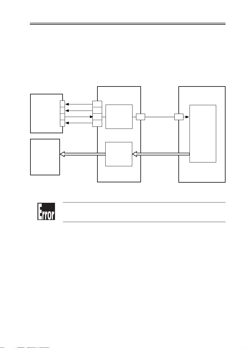
CHAPTER 4 IMAGE FORMATION SYSTEM
8.2 Monitoring the Waste Toner Case
The machine checks the waste toner case in reference to two levels.
The amount of waste toner inside the waste toner case is monitored by the waste toner
case full sensor (S2); the sensor is a pair of photosensors (light-emitting unit piece and
light-receiving piece). The machine will assume that the waste toner case has become full
when waste toner blocks the light between the two photosensors.
The DC controller PCB checks the waste toner case full sensor when the power is tuned
on and at time of delivery; it will assume a “waste toner full warning” after making a total of
100 prints (A4/LTR) after the waste toner case has become full, thereby indicating the Waste
Toner Case Full message on the control panel.
Thereafter, if the waste toner case is not replaced after making a total of about 2000 prints
(A4/LTR), the machine will indicate ‘E019’ on the control panel; the error code can be reset
by replacing the waste toner case and then turning off and then on the power switch.
If the waste toner case is not set, the light-blocking plate will block the light between the
photosensors, causing the Waste Toner Case Full message to appear.
The light between the photosensors is not visible to the eye.
Memo
DC controller PCB
Waste toner case
full sensor
(light-receiving)
4-24
Waste toner case
COPYRIGHT
©
2001 CANON INC. 2000 2000 2000 2000 CANON iR3300/2800/2200 REV.0 JAN. 2001
Waste toner case full signal
Waste toner case
full sensor
(light-emitting)
F04-802-01
+5V
J311-B7
-B9
a-B8

CHAPTER 4 IMAGE FORMATION SYSTEM
8.3 Locking of the Waste Toner Feedscrew
The waste toner feedscrew is rotated by the drive of the main motor transmitted by the
coupling built into the main motor drive assembly. The coupling is butted against the gear
used to rotate the screw by the work of a spring.
If the drum cleaning assembly is clogged with waste toner, the coupling will start to move
back and forth in the axial direction, causing a clicking sound.
The machine is not equipped with a sensor to detect the locking of the
Memo
Main motor
M1
waste toner feedscrew.
Photosensitive drum
Spring
Memo
COPYRIGHT
©
Coupling
Waste toner feedscrew
F04-803-01
E019
Indicates that the waste toner case is full.
The waste toner case can hold waste toner equivalent of about 200,000
prints.
2001 CANON INC. 2000 2000 2000 2000 CANON iR3300/2800/2200 REV.0 JAN. 2001
4-25

CHAPTER 4 IMAGE FORMATION SYSTEM
9.1 Pre-Exposure Lamp Unit
9.1.1 Handling of the Pre-Exposure Lamp Unit
1) Remove the drum unit. (See p. $.)
2) Remove the inside cover. (See p. $.)
3) Disconnect the connector [1], and remove the screw [2].
4) Take out the pre-exposure lamp unit [3].
[1]
[3]
F04-901-01
[2]
4-26
COPYRIGHT
©
2001 CANON INC. 2000 2000 2000 2000 CANON iR3300/2800/2200 REV.0 JAN. 2001

9.2 Photosensitive Drum
9.2.1 Removing the Drum Unit
1) Open the front cover.
2) Release the feeding assembly.
3) Release the developing assembly.
4) Remove the fixing screw [1].
5) Slide out the drum unit [2] slowly to the
front.
Take care not to damage or soil
the photosensitive drum.
Further, be sure to protect the
photosensitive drum against
light once it is outside the machine; it is highly susceptible to
light.
As many as 19 stirrups [1] (4
types) are attached to the bottom of the drum unit. Take care
not to crush them.
Further, be sure to place the
drum unit on a flat surface once
it has been removed out of the
machine.
CHAPTER 4 IMAGE FORMATION SYSTEM
[2]
[1]
F04-902-01
[1]
COPYRIGHT
©
F04-902-02
2001 CANON INC. 2000 2000 2000 2000 CANON iR3300/2800/2200 REV.0 JAN. 2001
4-27

CHAPTER 4 IMAGE FORMATION SYSTEM
9.2.2 Cleaning the Photosensitive Drum
If the surface of the photosensitive drum
has become soiled, wipe it with a flannel
cloth coated with toner. (Do not use paper,
lint-free or otherwise.)
Never dry-wipe the photosensitive drum or use solvent.
9.2.3 When Replacing the Drum Unit
Be sure to record the date of replacement
and the latest counter reading to the label
[1], and attach it to the front cover of the
drum unit; then, make adjustments according to the Image Adjustment Basic Procedure (p. $).
After replacing the drum unit,
be sure to perform the work under 7.7 “Removing Paper Lint.”
[1]
F04-902-03
4-28
COPYRIGHT
©
2001 CANON INC. 2000 2000 2000 2000 CANON iR3300/2800/2200 REV.0 JAN. 2001

CHAPTER 4 IMAGE FORMATION SYSTEM
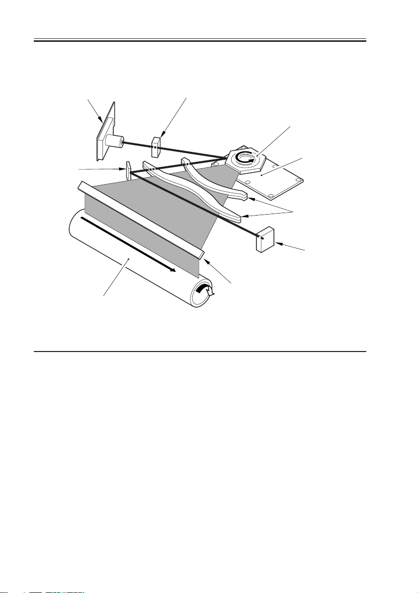
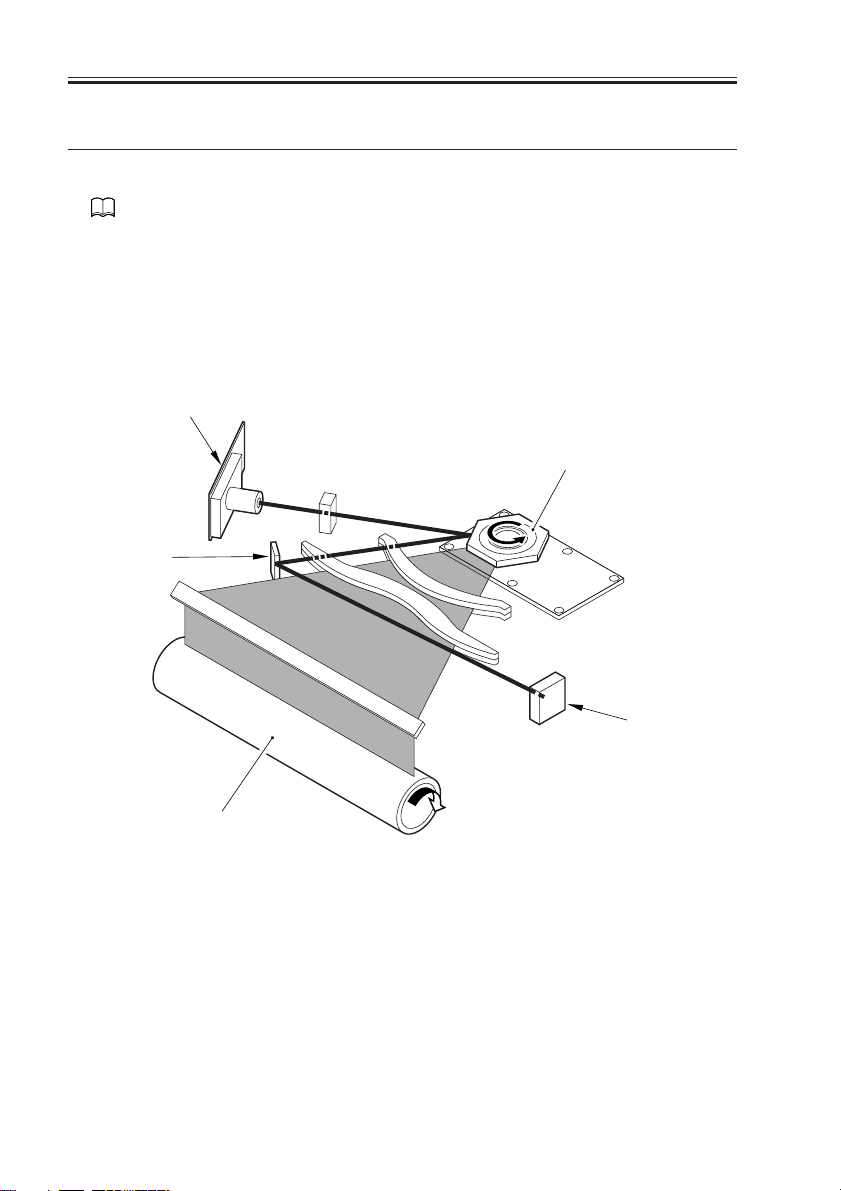
9.3 Transfer Charging Roller
9.3.1 Removing the Transfer Charging Roller
Do not touch the surface of the
transfer charging roller when
removing it. Otherwise, image
faults can occur.
1) Remove the feeding assembly. (See p.
$.)
2) Pull off the static eliminator [1].
3) Remove the screw [2], and detach the
hinge bin [3].
[3]
[2]
[1]
F04-903-01
4) Remove the transfer arm [1] equipped
with a spring to the left together with
the transfer charging roller [2].
5) Pull it off to the front.
COPYRIGHT
©
2001 CANON INC. 2000 2000 2000 2000 CANON iR3300/2800/2200 REV.0 JAN. 2001
[3]
[1]
F04-903-02
[2]
(1)
(2)
[4]
4-29

CHAPTER 4 IMAGE FORMATION SYSTEM
9.4 Charging Roller Solenoid
9.4.1 Removing the Charging
Roller Solenoid (SL6)
1) Remove the photosensitive drum. (See
p. $.)
2) Open the rear cover. (7 screws)
3) Remove the DC controller PCB. (see p.
$.)
4) Remove the four screws [1], and detach
the DC controller base [2].
[1]
[1]
[2]
5) Disconnect that two connectors [1] of
the harness.
6) Remove the three screws [2], and pull
out the duct unit [3] to the front.
7) Remove the claw, and detach the two
relay PCBs [1].
[1]
[2]
F04-904-01
[1]
[2]
F04-904-02
[1]
[1]
[3]
4-30
COPYRIGHT
F04-904-03
©
2001 CANON INC. 2000 2000 2000 2000 CANON iR3300/2800/2200 REV.0 JAN. 2001

8) Remove the faston [1] of the harness,
and detach the duct unit [2].
CHAPTER 4 IMAGE FORMATION SYSTEM
[1]
[2]
F04-904-04
9) Remove the two screws [1], and disconnect the connector [2]; then, detach the
charging roller solenoid [3].
[1]
[2]
[3]
F04-904-05
COPYRIGHT
©
2001 CANON INC. 2000 2000 2000 2000 CANON iR3300/2800/2200 REV.0 JAN. 2001
4-31

CHAPTER 4 IMAGE FORMATION SYSTEM
9.5 Developing Assembly
Keep the following in mind
when disassembling/assembling
the developing assembly:
1. When holding the developing
assembly, avoid touching the
developing cylinder.
2. After mounting the developing assembly, be sure to
mount the developing assembly stopper.
3. The blade and the blade base
of the blade base unit are adjusted at the factory to a high
accuracy; do not separate
them.
9.5.1 Removing the Developing Assembly
1) Open the front cover.
2) Shift down the developing assembly releasing lever [1] to free the developing
assembly [2].
3) Remove the screw [3], and lift the bottom of the developing assembly stopper
[4] to the front to remove it to the bottom.
4) Holding the grip of the developing assembly with one hand and supporting it
on its bottom with the other, pull it to
the front.
[3]
[2]
4-32
COPYRIGHT
[4]
(1)
[4]
(2)
[1]
F04-905-01
©
2001 CANON INC. 2000 2000 2000 2000 CANON iR3300/2800/2200 REV.0 JAN. 2001

9.5.2 Removing the Grip Assembly
1) Remove the developing assembly. (See
p. $.)
2) Remove the screw [1] and the three
claws [23], and detach the grip assembly [3].
CHAPTER 4 IMAGE FORMATION SYSTEM
[3]
[1]
F04-905-02
9.5.3 Removing the Tone Sensor
[3]
1) Remove the grip assembly. (See 7.6.2.)
2) Remove the two screws [1], and disconnect the connector [2].
3) Detach the toner sensor [3].
F04-905-03
9.5.4 Removing the Developing Assembly Upper Cover
1) Remove the grip assembly. (See 7.6.2.)
2) Remove the two screws [1] and the
three claws [2].
3) Remove the developing assembly upper
cover [3].
[2]
[2]
[1]
[2]
COPYRIGHT
©
[1]
F04-905-04
2001 CANON INC. 2000 2000 2000 2000 CANON iR3300/2800/2200 REV.0 JAN. 2001
[3]
4-33

CHAPTER 4 IMAGE FORMATION SYSTEM
9.5.5 Removing the Developing Cylinder
1) Remove the developing assembly upper
cover. (See p. $.)
2) Remove the two screws [1], and detach
the blade base unit [2].
[2]
The blade [1] and the blade base
[2] of the blade base unit are assembled to a high accuracy at
the factory. Do not separate
them.
9.5.6 Developing Assembly Cylinder
1) Remove the developing assembly upper
cover. (See p. $.)
2) Remove the E-ring [1], bearing [2], and
gear [3].
[1]
F04-905-05
[2]
[1]
F04-905-06
4-34
COPYRIGHT
[1]
[2]
[3]
F04-905-07
©
2001 CANON INC. 2000 2000 2000 2000 CANON iR3300/2800/2200 REV.0 JAN. 2001

3) Remove the two screws [1], and detach
the gear cover [2].
4) Remove the two gears [3].
CHAPTER 4 IMAGE FORMATION SYSTEM
[2]
[1]
[3]
F04-905-08
5) Put copy paper [3] between the developing cylinder [1] and the blade [2].
6) Remove the screw [1] and the grounding plate [2].
7) Remove the grip ring [3].
[1]
F04-905-09
[3]
[2]
[3]
[1]
[2]
COPYRIGHT
©
F04-905-10
2001 CANON INC. 2000 2000 2000 2000 CANON iR3300/2800/2200 REV.0 JAN. 2001
4-35

CHAPTER 4 IMAGE FORMATION SYSTEM
8) Remove the two screws [1], and detach
the member [2] and the front sleeve
holder [3].
9) Remove the two screws [1], and detach
the member [2] and the rear sleeve
holder [3].
10) Detach the developing cylinder [2] together with the two bearings [1].
[1]
[3]
F04-905-11
[2]
F04-905-12
[1]
F04-905-13
[1]
[3]
[1]
[2]
[1]
[1]
[2]
4-36
COPYRIGHT
©
2001 CANON INC. 2000 2000 2000 2000 CANON iR3300/2800/2200 REV.0 JAN. 2001

CHAPTER 4 IMAGE FORMATION SYSTEM
A
A
[1]
[2]
[3]
[1]([2])
9.5.7 Position of the Developing Assembly Magnetic Seal
1) Mount the front magnetic seal [1] and
the rear magnetic seal [2] while butting
them against the opening [3] (reference).
Check to be sure that the magnetic seal is in firm contact with
the housing.
9.5.8 Mounting the Developing Assembly Blade
F04-905-14
The blade [1] and the blade base
[2] of the blade base unit are assembled to high accuracy at the
factory. Do not separate them.
If you happened to have removed the
blade by mistake, be sure to adjust the position of the blade using a gap gauge (CK0057-000) so that the gap between the blade
and the developing cylinder [3] is 0.21±0.3
mm.
The surface of the developing
cylinder is susceptible to dam-
COPYRIGHT
age. Be sure to limit the gap
gauge to both sides of the developing cylinder.
©
2001 CANON INC. 2000 2000 2000 2000 CANON iR3300/2800/2200 REV.0 JAN. 2001
[2]
[1]
[3]
F04-905-15
4-37

CHAPTER 4 IMAGE FORMATION SYSTEM
9.6 Removing Paper Lint
9.6.1 Removing Paper Lint
1) Open the front cover.
2) Remove the lever cover [1].
3) Slide out the paper lint cleaning lever
[1], and move it back and forth.
[1]
F04-906-01
4-38
COPYRIGHT
[1]
F04-906-02
©
2001 CANON INC. 2000 2000 2000 2000 CANON iR3300/2800/2200 REV.0 JAN. 2001

9.7 Waste Toner Case
9.7.1 Replacing the W aste Toner Bottle
When the control panel indicates the Waste Toner Case Full
message, be sure to replace the
waste toner case.
Never use the waste toner case
for a second time. Otherwise,
the sensor will malfunction.
1) Remove the screw [1], and detach the
waste toner cover [2].
2) Remove the waste toner case [3].
CHAPTER 4 IMAGE FORMATION SYSTEM
[1]
[2]
[3]
F04-907-01
3) Remove the case cap [1] taped to the
waste toner case, and close the case.
4) Fit the new waste toner case [1], and
secure the waste toner cover [2] in place
with a screw [3].
[1]
[1]
F04-907-02
[3]
[2]
[1]
F04-907-03
COPYRIGHT
©
2001 CANON INC. 2000 2000 2000 2000 CANON iR3300/2800/2200 REV.0 JAN. 2001
4-39

CHAPTER 5
PICK-UP/FEEDING SYSTEM
COPYRIGHT
©
2001 CANON INC. 2000 2000 2000 2000 CANON iR3300/2800/2200 REV.0 JAN. 2001

CHAPTER 5 PICK-UP/FEEDING SYSTEM
1 Outline
1.1 Specifications and Construction
T05-101-01 shows the major functions and the construction of the pickup/feeding system:
Item Description
Paper feed reference Center
Paper stack Cassette (1, 2):500 sheets each (980 g/m2)
Multifeeder:50 sheets (80 g/m2)
Paper size switching Cassette 1:by user
Cassette 2 (100V model): by user
Cassette 2 (120/230V model):by service person
Multifeeder:by user
Duplex copying Through path
Related user mode Cassette auto selection (enabled/disabled)
Paper icon
Related mechanical adjustments Cassette horizontal registration adjustment
Multifeeder horizontal adjustment
T05-101-01
COPYRIGHT
©
2001 CANON INC. 2000 2000 2000 2000 CANON iR3300/2800/2200 REV.0 JAN. 2001
5-1

CHAPTER 5 PICK-UP/FEEDING SYSTEM
1.2 Arrangement of Rollers and Sensors
[12]
[11]
[10]
[8]
[7]
[9]
[13] [13]
F05-101-01
The following rollers are mainly used to move paper:
Ref. Name
[1] Pre-registration roller
[2] Registration roller
[3] Photosensitive drum
[4] Duplex roller
[5] Duplex roller
[6] Multifeeder pickup roller
[7] Pickup roller
[8] Feeding roller
[9] Separation roller
[6]
[1]
[2]
[1]
[5]
[3]
[4]
[2]
[14]
[4]
[3]
5-2
COPYRIGHT
©
2001 CANON INC. 2000 2000 2000 2000 CANON iR3300/2800/2200 REV.0 JAN. 2001

CHAPTER 5 PICK-UP/FEEDING SYSTEM
The following sensors are used to monitor the movement of paper:
Notation Name Delay jam Stationary jam Power-on
stationary jam
PS1 Cassette 1 paper sensor No No N o
PS2 Cassette 2 paper sensor No No N o
PS7 Cassette 1 retry paper sensor Yes No No
PS8 Cassette 2 retry paper sensor Yes No No
PS9 Pre-registration paper sensor Yes No No
PS10 Registration paper sensor Yes Yes No
PS11 Horizontal registration paper sensor Yes No No
PS12 Image leading edge paper sensor Yes No No
PS13 fixing feeding sensor Yes Yes No
PS15 No. 1 delivery paper sensor Yes Yes No
PS16 No. 1 delivery full sensor No No N o
PS17 Duplex inlet paper sensor Yes N o No
PS18 Duplex outlet paper sensor Yes No No
PS22 Multifeeder paper sensor N o No No
T05-102-01
COPYRIGHT
©
2001 CANON INC. 2000 2000 2000 2000 CANON iR3300/2800/2200 REV.0 JAN. 2001
5-3

CHAPTER 5 PICK-UP/FEEDING SYSTEM
1.3 Arrangement of Motors, Clutches, and Solenoids
M1M5
M9
M6
CL2
SL1
F05-103-01
The following motors, clutches, and solenoids are used to move paper:
Notation Name
M1 Main motor
M2 Pickup motor
M5 Delivery motor
M6 Duplex motor
M9 Registration motor
CL1 Vertical path clutch
CL2 Multifeeder clutch
SL1 Pickup DOWN solenoid
SL5 Multifeeder rely releasing solenoid
SL5
CL1
M2
5-4
COPYRIGHT
©
2001 CANON INC. 2000 2000 2000 2000 CANON iR3300/2800/2200 REV.0 JAN. 2001

CHAPTER 5 PICK-UP/FEEDING SYSTEM
2 Detecting Jams
2.1 Sequence of Operations (jam detection)
2.1.1 Delay Jam
a. Cassette Pickup Assembly (cassette 1, 2)
The leading edge of paper does not reach the sensor within a specific period of time after
the motor has gone ON.
Start key ON
or
PRINT setting ON
INTR / PRINT
Motor N-1
Jam check
Sensor N
[1]
Normal
[1]:specific feed period.
[1]
Error
F05-201-01
Pickup assembly Motor Sensor
Cassette 1 Pickup motor (M2) Cassette 1 retry sensor (PS7)
Cassette 2 Pickup motor (M2) Cassette 2 retry sensor (PS8)
T05-201-01
COPYRIGHT
©
2001 CANON INC. 2000 2000 2000 2000 CANON iR3300/2800/2200 REV.0 JAN. 2001
5-5

CHAPTER 5 PICK-UP/FEEDING SYSTEM
b. Other Delay Jams
Other than pickup sensor delay jams, jams are found by other sensors at the following
timing of detection.
The period of time for travel between sensor N-1 and delay jam sensor N are monitored
with reference to the clock pulses from the main motor; a delay jam will be identified if the
leading edge of paper does not reach the delay jam sensor N in question within a specific
period of time after the sensor N-1 goes ON.
Start key ON
PRINT settings ON
or
INTR / PRINT
Sensor N-1
Jam check
Sensor N
[1] [1]
Normal
[1]:specific feed period.
F05-201-02
Notation Name Delay jam
PS9 Pre-registration paper sensor Yes
PS10 Registration paper sensor Yes
PS11 Horizontal registration paper sensor Yes
PS12 Image leading edge sensor Yes
PS13 Fixing feeding sensor Yes
PS15 No. 1 delivery paper sensor Yes
PS17 Duplex inlet paper sensor Yes
PS18 Duplex outlet paper sensor Yes
PS22 Multifeeder paper No
T05-201-02
Error
5-6
COPYRIGHT
©
2001 CANON INC. 2000 2000 2000 2000 CANON iR3300/2800/2200 REV.0 JAN. 2001

CHAPTER 5 PICK-UP/FEEDING SYSTEM
2.1.2 Stationary Jam
a. Common Stationary Jam
Registration paper sensor (PS10), Fixing feeding sensor (PS13), No. 1 delivery paper sen-
sor (PS15)
Start key ON
or
PRINT setting ON
INTR / PRINT
Jam check
Sensor N
L + A
Normal
(L: paper length; A: specific feed distance)
L + A
Error
F05-201-03
b. Power-On Stationary Jam
A stationary jam at power on is identified based on the presence/absence of paper over a
specific sensor about 1 sec after the control panel power switch is turned on.
2.1.3 Jam History
The host machine maintains a history of jams that occur inside it, and the history may be
checked in service mode.
COPIER>DIPLAY>JAM
Use it to indicate jam data.
COPIER>FUNCTION>JAM-HIST
Use it to clear the jam history.
The following are retained in response to a jam, and brought back to use after the jam has
been removed.
• Remaining number of copies to make
• Selected copying mode
COPYRIGHT
©
2001 CANON INC. 2000 2000 2000 2000 CANON iR3300/2800/2200 REV.0 JAN. 2001
5-7

CHAPTER 5 PICK-UP/FEEDING SYSTEM
3 Pickup Assembly
3.1 Pickup Control System
[10]
M9
[11]
M2
Notation Name
[1] Gear
[2] Pickup roller
[3] Feeding roller
[4] Separation roller
[5] Lifter
[6] Vertical path roller
[7] Ca m
[8] Registration roller
[1]
[2]
[5]
[8]
[3]
[2]
[5]
F05-301-01
[11]
[9]
CL1
[4]
[6]
[3]
[4]
Notation Name
[9] Pre-registration roller
[10] DC controller PCB
[11] Cassette pickup PCB
M1 Main motor
M2 Pickup motor
M5 Registration motor
CL1 Vertical path clutch
SL1 Pickup DOWN solenoid
SL1
M1
[7]
5-8
COPYRIGHT
©
2001 CANON INC. 2000 2000 2000 2000 CANON iR3300/2800/2200 REV.0 JAN. 2001

CHAPTER 5 PICK-UP/FEEDING SYSTEM
3.2 Outline
The paper inside the cassette is held up by the lifter, and remains in contact with the
pickup roller when pickup takes place:
(1) The pickup motor (M2) is used to drive the pickup roller. The pickup roller is moved
down in relation to the feeding roller, and is brought into contact with paper only when
pickup takes place.
(2) The pickup roller is moved down when the cam released by the DOWN solenoid
(SL1) rotates by the drive of the main motor (M1).
The feeding roller and the separation roller serve to make sure that only one sheet of paper from the pickup roller is sent to the feeding path; the No. 2 registration roller and the
vertical path roller then forwards the paper as far as the registration roller.
The drive for the vertical path roller and the No. 2 registration roller is provided by the
pickup motor (M2) through the vertical path clutch (CL1).
The registration roller is driven by the registration motor (M9).
COPYRIGHT
©
2001 CANON INC. 2000 2000 2000 2000 CANON iR3300/2800/2200 REV.0 JAN. 2001
5-9

CHAPTER 5 PICK-UP/FEEDING SYSTEM
3.3 Sequence of Operations (pickup)
a. Cassette 1
• A4, 2 Copies, Continuous
Start key ON
INTR LSTR
Cassette 1 pickup
solenoid
Pickup motor
Retry sensor
Vertical path roller
clutch
Pre-registration
paper sensor
Registration paper
sensor
Registration motor
F05-303-01 Sequence of Operations (cassette)
PRINT
5-10
COPYRIGHT
©
2001 CANON INC. 2000 2000 2000 2000 CANON iR3300/2800/2200 REV.0 JAN. 2001

CHAPTER 5 PICK-UP/FEEDING SYSTEM
3.4 Operation of the Cassette Lifter
The lifter is operated as necessary in the course of printing to maintain the stack of sheets
to a specific height.
3.4.1 Operation of the Lifter During Printing
The lifter is controlled by the movement of the pickup roller shaft. When the pickup roller
shaft pushes the lifter trigger lever, the cam is released, and the lifter starts to move up until
the lifter trigger lever stops the cam.
1) Each time the pickup roller DOWN so-
lenoid (SL1) goes ON, the pickup roller
shaft [2] moves down to initiate pickup
operation.
2) When the sheets decrease and, as a re-
sult, the descent distance [3] of the
pickup roller increases, the pickup roller
shift pushes down the lifter trigger lever
[4].
3) When the lever is pushed down, the cam
[5] is released, causing it to rotate.
4) The rotation of the cam turns the eccen-
tric cam [3] mounted to the same shaft.
The eccentric cam operates the lifter UP
lever [2] to move up the lifter gear [1].
5) The lifter moves up and, as a result, the
paper stack moves up; when the pickup
roller shaft reaches a specific height, the
lifter trigger lever is drawn back by the
work of a spring, thereby stopping the
cam.
SL1
[7]
[1]
[2]
[3]
[4]
[6]
[5]
The foregoing series of operation is repeated to maintain the height of the paper
stack to a specific level. The cassette pickup
operation ends when paper runs out and the
cassette paper sensor detects the absence of
paper.
F05-304-01 Cassette Lifter Operation
COPYRIGHT
©
2001 CANON INC. 2000 2000 2000 2000 CANON iR3300/2800/2200 REV.0 JAN. 2001
[1]
[2]
[3]
5-11

CHAPTER 5 PICK-UP/FEEDING SYSTEM
3.4.2 Releasing the Lifter
The lifter is released mechanically when the cassette is slid out. When the machine is in
standby state, the lifter gear is held in place by the lifter gear retaining lever. When the cassette is slid out, the lifter gear retaining lever is freed, thereby allowing the lifter to move
down.
If the main power is cut while the lifter is moving up, the lifter is held up
with the claw used to move up the lifter remaining in contact with the lifter
gear; the lifter will not be fully released in this condition, and damage can
occur if the cassette is forced out. Be sure to turn off and then on the main
power so that the machine will be in standby state whenever the cassette
must be slid out.
5-12
COPYRIGHT
©
2001 CANON INC. 2000 2000 2000 2000 CANON iR3300/2800/2200 REV.0 JAN. 2001

CHAPTER 5 PICK-UP/FEEDING SYSTEM
3.5 Cassette Pickup Operation
3.5.1 Rotating the Pickup Roller
The drive used to rotate the pickup roller is transmitted through gears. The cassette motor
rotates clockwise and counterclockwise to initiate pickup operation of the cassette 1/2.
3.5.2 Switching the Pickup Roller Drive
When the pickup roller rotates clockwise, the gear 1 moves up to drive the pickup roller
of the upper cassette holder; when the motor rotates counterclockwise, on the other hand,
the gear 1 moves down to drive the pickup roller of the lower cassette holder. The figure below shows how the drive of the pickup roller is controlled.
3.5.3 Pickup Roller Shaft Reference
The up and down movement of the pickup roller when the cassette is set in the machine is
driven with reference to the position of the pickup roller shaft.
[1]
[2]
COPYRIGHT
©
F05-305-01
2001 CANON INC. 2000 2000 2000 2000 CANON iR3300/2800/2200 REV.0 JAN. 2001
5-13

CHAPTER 5 PICK-UP/FEEDING SYSTEM
Cassette pickup motor (M5)
Gear 1
Feeding roller
Pickup roller
Separation roller
F05-305-02
F05-305-03
Pickup Drive for the Upper Cassette Holder (pickup motor in CW rotation)
Feeding roller
Cassette pickup motor (M5)
Pickup roller
Separation roller
Gear 1
Pickup Drive for the Lower Cassette Holder (pickup motor CCW rotation)
5-14
COPYRIGHT
©
2001 CANON INC. 2000 2000 2000 2000 CANON iR3300/2800/2200 REV.0 JAN. 2001

CHAPTER 5 PICK-UP/FEEDING SYSTEM
3.6 Moving Up/Down the Pickup Roller
The pickup roller and the feeding roller are supported by a roller holder, and the pickup
roller is moved up and down in relation to the feeding roller. In standby state, the pickup
roller is at the uppermost position; during pickup operation, on the other hand, it moves
down to reach the paper surface. It operates as follows to pick up a single sheet of paper:
1) When the pickup solenoid (SL1) goes ON, the drive of the main motor (M1) causes the
cam 1 to rotate.
2) The rotation of the cam 1 causes the pickup lever to swing.
3) The swing of the lever causes the pickup roller to move down to come into contact with
the paper, and the pickup motor (M2) starts pickup operation.
4) The rotation of the cam 1 moves up the pickup roller shaft.
Roller holder
Pickup roller
shaft
COPYRIGHT
©
F05-306-01 Arrangement of the Pickup Roller
Feeding roller
Feeding roller shaft
Pickup roller shaft
Pickup lever
Pickup solenoid
(SL1)
Roller holder
Cam 1
ON
(rotates when SL1 goes ON)
ON
Pickup roller
F05-306-02 Up/Down Movement of the Pickup Roller Shaft
2001 CANON INC. 2000 2000 2000 2000 CANON iR3300/2800/2200 REV.0 JAN. 2001
5-15

CHAPTER 5 PICK-UP/FEEDING SYSTEM
3.7
Detecting the Presence/Absence of Paper Inside the Cassette
When the cassette runs out of paper, the paper detecting lever falls through the detecting
hole of the cassette, causing the light-blocking plate linked to the lever to block the light of
the photointerrupter (Q1604 for cassette 1; Q1605 for cassette 2).
Q1604: cassette 1.
Q1605: cassette 2.
Paper detecting lever
F05-307-01 Arrangement of the Paper Detecting Lever
5-16
COPYRIGHT
©
2001 CANON INC. 2000 2000 2000 2000 CANON iR3300/2800/2200 REV.0 JAN. 2001

CHAPTER 5 PICK-UP/FEEDING SYSTEM
3.8 Pickup Retry Operation
When a delay is detected by a pickup sensor because of wear on the pick roller, pickup
retry operation is executed. If a delay is still detected after a retry, the control panel indicates
the Jam message.
3.8.1 Conditions for Detecting a Delay
Paper does not reach the retry sensor when it has been moved over a specific distance after the pickup DOWN solenoid (SL1) has gone ON.
Start key ON
Pick DOWN solenoid
Pickup motor
Retry paper sensor
Vertical path sensor
*1:retry operation is executed if paper does not arrive after moving it over ‘distance to the retry sen-
sor + 100 mm’.
Retry operation started
*1
Hereafter, the same
sequence as common
pickup sequence.
F05-308-01 Retry Operation
COPYRIGHT
©
2001 CANON INC. 2000 2000 2000 2000 CANON iR3300/2800/2200 REV.0 JAN. 2001
5-17

CHAPTER 5 PICK-UP/FEEDING SYSTEM
3.8.2 Paper Retraction
If a delay is detected once again after a retry and the jam must be removed, the paper can
become torn if an attempt is made form the cassette side. To enable removal from the right
cover side, the following operation takes plate:
1) After detecting the jam, the retracting roller is driven for a period equivalent to a dis-
tance over which paper may be moved 10 cm. The paper will be moved to a point where
it is in view when the right cover is opened.
2) The control panel indicates an instruction to the effect that the jam may be removed
from the right cover side.
3) The right cover may be opened to remove the jam. If the jam is not in view when the
right cover is opened, it may be removed from the cassette side.
Jam indicator
Start key ON Retry started
Pickup roller DOWN
solenoid
Pickup motor
Pickup sensor
*1:paper does not arrive about 1 sec after detection.
*2:paper moved by the retracting roller for a equivalent of a distance over which paper may be
moved 10 cm.
*1
(removal from right cover side)
*2
*1
5-18
COPYRIGHT
F05-308-02
©
2001 CANON INC. 2000 2000 2000 2000 CANON iR3300/2800/2200 REV.0 JAN. 2001

CHAPTER 5 PICK-UP/FEEDING SYSTEM
3.9 Operation Other Than Cassette Pickup (standby)
When the cassette is slid into or out of the machine, the following takes place:
3.9.1
Moving Up the Lifter/Moving Down the Pickup Roller Shaft (cassette slid in)
1) Moving Down the Pickup Roller Shaft
With the power on, when the cassette is slid into the machine, the pickup roller moves
down until it comes into contact with the paper surface as follows:
• The cassette rear end pushes in the lever 1 of the pickup unit.
• When the cassette size detection mechanism goes ON, the main motor (M1) and the
pickup solenoid (SL1) go ON to swing the pickup lever.
■ The pickup roller shaft is subject to the moment of the lever 1 and the pickup lever.
Pickup roller shaft
Feeding roller
Lever 1
Cassette
Pickup roller
F05-309-01 Movement of the Lever 1 When the Cassette Is Slid In
2) Moving Up the Lifter
When the main power is turned on with the cassette set in the machine or the cassette is
slid in while the machine is in standby state, the pickup roller shaft moves down to push
down the lifter trigger lever.
The cam is released when the pickup roller shaft pushes one side of the lifter trigger lever,
and the drive from the main motor (M1) move sup the lifter.
When the pickup roller remaining in contact with the paper surface moves up to a specific
height, the movement of the levers cause the pickup roller shaft to return to the uppermost
position to end the upward movement of the lifter.
COPYRIGHT
©
2001 CANON INC. 2000 2000 2000 2000 CANON iR3300/2800/2200 REV.0 JAN. 2001
5-19

CHAPTER 5 PICK-UP/FEEDING SYSTEM
Pickup roller shaft
Lifter trigger lever
Cam
M1
F05-309-02 Moving Up the Lifter
3.9.2 Moving Up the Pickup Roller Shaft and Releasing the Separation
Roller Pressure (cassette slid out)
When the cassette is slid out of the machine, the pickup roller shaft is mechanically
moved up and the separation roller pressure is also released.
1) Moving Up the Pickup Roller Shaft and Releasing the Separation Roller Pressure
When the cassette is slid out, the lever 1 rotates by the work of a spring. When the lever 1
rotates, the pickup roller shaft moves so that the pickup roller and the cassette will not interfere with each other.
Pickup roller shaft
Spring
Lever 1
Cassette
Feeding roller
Pickup roller
F05-309-03 Moving Up the Pickup Roller Shaft
2) Releasing the Separation Roller Pressure
The lever 1 is provided with a protrusion used to push down the separation roller assembly. When the cassette is slid out, the lever 1 rotates causing the separation roller to move
down, thereby removing the pressure between the separation roller and the feeding roller.
5-20
COPYRIGHT
©
2001 CANON INC. 2000 2000 2000 2000 CANON iR3300/2800/2200 REV.0 JAN. 2001

CHAPTER 5 PICK-UP/FEEDING SYSTEM
Protrusion of lever 1
Separation roller
Cassette
F05-309-04 Releasing the Separation Roller
b. Releasing the Lifter
The lifter is released when the cassette is slid out while the machine is in standby state.
3.10 Detecting the Level of Paper
The level of paper inside the cassette is detected by the light-blocking plate of the lifter
gear and a sensor in relation to the distance over which the lifter moves up. When paper
starts to run out, the lifter gradually moves up; when paper fully runs out, the cassette paper
sensor (Q1604 for cassette 1) identifies the condition as indicating the absence of paper.
COPYRIGHT
©
Lifter
Light-blocking plate
F05-310-01
2001 CANON INC. 2000 2000 2000 2000 CANON iR3300/2800/2200 REV.0 JAN. 2001
5-21

CHAPTER 5 PICK-UP/FEEDING SYSTEM
If the cassette is full of paper If the cassette is empty of paper
Pickup roller
Paper
Sensor 2
Sensor 1
Lifter
Note: The diagram is a view from the rear of the copying machine.
Light-blocking plate
F05-310-02 Detecting the Level of Paper in the Cassette (upper cassette holder)
The amount of paper inside the cassette is indicated on the control panel in terms of four
levels (including the absence of paper).
Indication Level Sensor 1 Sensor 2
3 bars 100% to about 50% of capacity 0 0
2 bars 50% to about 10% of capacity 1 0
1 bar about 10% or less of capacity 1 1
no bar No paper - -
0: light-blocking plate over the sensor.
1: light-blocking plate not over the sensor.
T05-310-01
5-22
COPYRIGHT
©
2001 CANON INC. 2000 2000 2000 2000 CANON iR3300/2800/2200 REV.0 JAN. 2001

CHAPTER 5 PICK-UP/FEEDING SYSTEM
4 Identifying the Size of Paper
The size of paper inside the cassette may be set using the dial on the cassette. The ABsetting and the Inch-setting are switched over using the switch found next to the dial.
4.1 Identifying the Size
The dial on the cassette may be set to any of 16 stops.
When the dial is set to an appropriate paper size and the cassette is slid into the machine,
the four cassette size detecting switches recognize the size of the paper based on the resulting combination of indentations and protrusions of the size detecting cam.
4.2 AB-/Inch-Setting Switch
The AB-setting and the Inch-setting is switched over using the switch found next to the
dial.
When the cassette is slid into the machine, the cassette side detecting switch recognizes
the paper configuration (AB or Inch)
[1]
Ref. Name
[1] Dial
[2] AB-/Inch-setting switch
[3] Size detecting cam
COPYRIGHT
©
2001 CANON INC. 2000 2000 2000 2000 CANON iR3300/2800/2200 REV.0 JAN. 2001
[3]
[2]
F05-402-01
5-23

CHAPTER 5 PICK-UP/FEEDING SYSTEM
4.3 Paper Size
The width and the length of paper are identified by the CPU of the machine with reference to how the dial mounted to the cassette is set. The following diagram shows the rotary
label attached to the dial, and the following table shows the paper sizes that are recognized
by the machine:
A5R
B4
U1
A5
U2
SP-2
SP-1
3
U
A4
A4R
A3
B5
B5R
A/B-setting rotary label Inch-setting rotary label
F05-403-01 Rotary Label
Note 1: U Cassette
The following are special types of paper:
U1...FOOLSCAP U2...FOLIO
U8...K-LGL(R)
OFFICIO U3...A-FLS
A-OFFICIO U4...G-LTR
LGL
11×17
LTR
LTR-R
U4
STMT-R
U5
U6
STMT
8
U7
SP-4
SP-3
U
E-OFFICIO U5...G-LTR(R)
B-OFFICIO U6...G-LGL
A-LGL U7...X-LGL
Note 2:SP-1, -2 (SPECIAL 1, 2)
A default size paper that suits t the needs of the user may be registered in user mode. A
SPECIAL cassette icon may be indicated on the control panel for immediate access. For details, see the User’s Manual.
5-24
COPYRIGHT
©
2001 CANON INC. 2000 2000 2000 2000 CANON iR3300/2800/2200 REV.0 JAN. 2001
 Loading...