

iR2200/iR2800/
iR3300
REVISION 0
MAR. 2001
COPYRIGHT© 2001 CANON INC. CANON iR2200/iR2800/iR3300 REV.0 MAR. 2001 PRINTED IN U.S.A.
FY8-13H8-000

Application
This manual has been issued by Canon Inc. for qualified persons to learn technical
theory, installation, maintenance, and repair of products. This manual covers all
localities where the products are sold. For this reason, there may be information in this
manual that does not apply to your locality.
Corrections
This manual may contain technical inaccuracies or typographical errors due to
improvements or changes in products. When changes occur in applicable products or in
the contents of this manual, Canon will release technical information as the need arises.
In the event of major changes in the contents of this manual over a long or short period,
Canon will issue a new edition of this manual.
The following paragraph does not apply to any countries where such provisions are
inconsistent with local law.
Trademarks
The product names and company names used in this manual are the registered
trademarks of the individual companies.
Copyright
This manual is copyrighted with all rights reserved. Under the copyright laws, this
manual may not be copied, reproduced or translated into another language, in whole or
in part, without the written consent of Canon Inc.
COPYRIGHT © 2001 CANON INC.
Printed in U.S.A.
Imprimé au U.S.A.
Caution
Use of this manual should be strictly supervised to avoid disclosure of confidential information.
COPYRIGHT© 2001 CANON INC. CANON iR2200/iR2800/iR3300 REV.0 MAR. 2001 PRINTED IN U.S.A.
INTRODUCTION
1 Symbols Used
This documentation uses the following symbols to indicate special information:
Symbol Description
Indicates an item of a non-specific nature, possibly classified as Note, Caution,
or Warning.
Indicates an item requiring care to avoid electric shocks.
Indicates an item requiring care to avoid combustion (fire).
Indicates an item prohibiting disassembly to avoid electric shocks or problems.
Indicates an item requiring disconnection of the power plug from the electric
outlet.
Indicates an item intended to provide notes assisting the understanding of the
Memo
topic in question.
REF.
COPYRIGHT
©
Indicates an item of reference assisting the understanding of the topic in question.
Provides a description of a service mode.
Provides a description of the nature of an error indication.
Refers to the Copier Basics Series for a better understanding of the contents.
2001 CANON INC. 2000 2000 2000 2000 CANON iR2200/iR2800/iR3300 REV.0 MAR. 2001
i

INTRODUCTION
2 Outline of the Manual
This Service Manual contains basic information needed to service the iR2200/iR2800/
iR3300 and its accessories (i.e., side paper deck, shift tray) in the field, conducted for the
purpose of maintaining its product quality and a specific level of performance. A separate
Service Manual is made available for each of its accessories (except for the side paper deck
and shift tray); for details, refer to the appropriate manual.
This Service Manual consists of the following chapters:
1. System Unit
Chapter 1 General Description: features, specifications, names of parts, func-
tions, operation, system configuration, routine maintenance by the user
Chapter 2 Main Controller: functional construction, outline of electrical
circuitry, principles of operation of the image
processing system, power supply
Chapter 3 Installation: site conditions and installation procedure,
relocation of the machine, installation of accessories
2. Reader Unit
Chapter 1 Basic Operation: functional construction, outline of electrical
circuitry, basic sequence of operations
Chapter 2 Original Exposure System: principles of operation of the exposure sys-
tem, timing of operation, disassembly/assembly and adjustment
Chapter 3 Image Processing System: principles of operation of the image process-
ing system, timing of operation, disassembly/
assembly and adjustment
3. Printer Unit
Chapter 1 Introduction: safety of the laser, image formation, auxiliary
processes
Chapter 2 Sequence of Operations: basic operations, outline of electrical cir-
cuitry, basic sequence of operations
Chapter 3 Laser Exposure System: principles of operation of the laser exposure
system, timing of operation, disassembly/
assembly and adjustment
Chapter 4 Image Formation System: principles of operation of the image forma-
tion system, timing of operation, disassembly/assembly and adjustment
Chapter 5 Pickup/Feeding System: principles of operation of the pickup/feeding
system, timing of operation, disassembly/
assembly and adjustment
ii
COPYRIGHT
©
2001 CANON INC. 2000 2000 2000 2000 CANON iR2200/iR2800/iR3300 REV.0 MAR. 2001

INTRODUCTION
Chapter 6 Fixing System: principles of operation of the fixing system,
timing of operation, and disassembly/assembly and adjustment
Chapter 7 Externals and Controls: principles of operation of the externals/con-
trols, timing of operation, disassembly/assembly and adjustment
Chapter 8 Paper Deck-L1: principles of operation, timing of operation,
disassembly/assembly and adjustment
Chapter 9 Casstte Feeding Unit-W1: principles of operation, timing of operation,
disassembly/assembly adjustment
Chapter 10 Inner 2Way Tray-A1: principles of operation, timing of operation,
disassembly/assembly adjustment
Chapter 11 Envelope Feeder Attachment-B1:
principles of operation, timing of
operation,disassembly/assembly adjustment
4. Troubleshooting
Chapter 1 Maintenance and Inspection: table of periodically replaced parts, table of
consumables/durables, scheduled servicing
chart
Chapter 2 Image Adjustment Basic Procedure:
basic procedure for image adjustment
Chapter 3 Standards and Adjustments: standards and adjustments
Chapter 4 Troubleshooting Image Faults/Malfunctions:
troubleshooting image faults/malfunctions
Chapter 5 Service Mode: how to use service mode, list of service
modes
Chapter 6 Self Diagnosis: codes, causes of errors
Chapter 7 Upgrading: how to upgrade
Appendix: general timing chart, general circuit diagrams
The descriptions are updated from time to time to reflect product improvements, and ma-
jor changes are communicated in the form of Service Information bulletins.
All service persons are expected to familiarize themselves with the contents of this Ser-
vice Manual and Service Information bulletins and acquire a level of knowledge and skill
required to promptly respond to the needs of the field.
COPYRIGHT
©
2001 CANON INC. 2000 2000 2000 2000 CANON iR2200/iR2800/iR3300 REV.0 MAR. 2001
iii

INTRODUCTION
The following rules apply throughout this Service Manual:
1. Each chapter contains sections explaining the purpose of specific functions and the relationship between electrical and mechanical systems with reference to the timing of
operation.
In the diagrams, represents the path of mechanical drive; where a signal name
accompanies the symbol , the arrow indicates the direction of the electric signal.
The expression “turn on the power” means flipping on the power switch, closing the
front door, and closing the delivery unit door, which results in supplying the machine
with power.
2. In the digital circuits, ‘1’ is used to indicate that the voltage level of a given signal is
“High,” while ‘0’ is used to indica te “Low.” (The voltage value, however, differs from
circuit to circuit.) In addition, the asterisk (*) as in “DRMD*” indicates that the
DRMD signal goes on when ‘0’.
In practically all cases, the internal mechanisms of a microprocessor cannot be
checked in the field. Therefore, the operations of the microprocessors used in the machines are not discussed: they are explained in terms of from sensors to the input of the
DC controller PCB and from the output of the DC controller PCB to the loads.
The descriptions in this Service Manual are subject to change without notice for product
improvement or other purposes, and major changes will be communicated in the form of
Service Information bulletins.
All service persons are expected to have a good understanding of the contents of this Service Manual and all relevant Service Information bulletins and be able to identify and isolate
faults in the machine.
iv
COPYRIGHT
©
2001 CANON INC. 2000 2000 2000 2000 CANON iR2200/iR2800/iR3300 REV.0 MAR. 2001
SYSTEM UNIT
COPYRIGHT
©
2001 CANON INC. 2000 2000 2000 2000 CANON iR2200/iR2800/iR3300 REV.0 MAR. 2001

Contents
CHAPTER 1 GENERAL DESCRIPTION
1 Specifications .................................1-1S
1.1 Main Body ...............................1-1S
1.1.1 Type ...................................1-1S
1.1.2 Systems..............................1-1S
1.1.3 Functions ...........................1-2S
1.1.4 Others ................................1-5S
1.2 Side Paper Deck-L1 .................1-8S
2 Names of Parts ...............................1-9S
2.1 External Vie w...........................1-9S
2.2 Cross Section .........................1-11S
3 System Configuration .................. 1-1 3S
3.1 Functional Construction ........ 1- 13S
CHAPTER 2 MAIN CONTROLLER
1 Basic Construction .........................2-1S
1.1 Functional Construction .......... 2-1S
1.2 Outline of the Electrical Circuitry
.................................................2-2S
1.2.1 Outline ...............................2-2S
1.2.2 Main Controller PCB ......... 2-2S
1.2.3 HDD ..................................2-2S
1.3 Start-Up Sequence ...................2-4S
1.3.1 Outline ...............................2-4S
1.3.2 Start-Up Sequence ............. 2-5S
2 Digital Image Processing ...............2-7S
2.1 Outline ..................................... 2-7S
2.2 Input Image Processing............2-8S
2.2.1 Image Data from the Reader
Unit ....................................2-8S
2.2.2 Enlargement/Reduction (main
scanning direction) ............2-8S
2.2.3 Edge Emphasis .................. 2-8S
2.2.4 Editing ...............................2-8S
2.2.5 Density Conversion (LUT)
...........................................2-8S
3.2 Outline of the Electrical Circuitry
...............................................1-14S
3.2.1 Construction of the Electrical
Circuit ..............................1-14S
3.3 Inputs to and Outputs from the Ma-
jor PCBs ................................. 1-15S
3.3.1 Wiring Diagram of the Major
PCBs ................................1-15S
3.4 Configuration with Accessories
...............................................1-16S
3.4.1 Accessories for Original/Paper
Feeding ............................ 1-16S
3.4.2 Accessory Boards ............1-17S
2.2.6 Binary Processing (error diffu-
sion method T-BIC) ........... 2-9S
2.2.7 Binary (dither screen method)
...........................................2-9S
2.3 Image Memory Control ...........2-9S
2.3.1 Compression/De-Compression,
Rotation, and Enlargement/Re-
duction ...............................2-9S
2.3.2 SDRAM.............................2-9S
2.3.3 HDD ..................................2-9S
2.4 Output Image Processing .......2-10S
2.4.1 Smoothing .......................2-10S
2.4.2 Binary-Binary Density Conversion (read image output only)
.........................................2-10S
3 Soft Counters................................2-11S
4 Controlling the Power Supply......2-15S
4.1 Outline ................................... 2-15S
4.2 Power Supply Modes .............2-15S
4.3 Standby Mode (normal operation)
...............................................2-15S
4.4 Sleep Mode 1 ......................... 2 -15S
CONTENTS
COPYRIGHT
©
2001 CANON INC. 2000 2000 2000 2000 CANON iR2200/iR2800/iR3300 REV.0 MAR. 2001
S1

CONTENTS
4.4.1 Shift from Standby Mode to
Sleep Mode 1 ................... 2-16 S
4.4.2 Shift from Sleep Mode 1 to
Standby Mode.................. 2- 16S
4.5 Sleep Mode 2 ......................... 2 -17S
4.5.1 Shift from Standby Mode to
Sleep Mode 2 ................... 2-17 S
4.5.2 Shift from Sleep Mode 2 to
Standby Mode.................. 2- 17S
CHAPTER 3 INSTALLATION
1 Selecting the Site of Installation ....3-1S
2 Unpacking and Installation ............3-3S
2.1 Before Starting the Work .........3-3S
2.2 Unpacking and Removing the Fix-
ing Materials ............................ 3-4S
2.3 Mounting the Scanner .............. 3-6S
2.4 Removing the Dummy Drum....3-6S
2.5 Supplying the Toner .................3-7S
2.6 Mounting the Drum Unit .......3-10S
2.7 Stirring the Toner ...................3-12S
2.8 Setting the Cassette ................3-13S
2.9 Checking the Images/Operations
...............................................3-16S
2.10 Connecting to the Network .... 3-18S
2.11 Checking the Network Connection
...............................................3-18S
2.11.1 Using the PING Function
.........................................3-18S
4.5.3 Shift from Sleep Mode 2 to
Sleep Mode 1 ................... 2-17 S
4.6 Turning Off the Power ........... 2-17 S
5 New Functions .............................2-18S
5.1 Hard Disk Spool .................... 2-18S
5.2 SMB Printing .........................2-19S
5.3 LPD Banner ...........................2-20S
2.11.2 Making a Check Using a Re-
mote Host Address...........3-19S
2.12 Troubleshooting the Network
...............................................3-19S
2.12.1 Checking the Connection of the
Network Cable ................. 3- 19S
2.12.2 Making a Check Using a Loop-
Back Address ...................3-20S
2.12.3 Making a Check Using a Local
Host Address....................3-20S
3 Relocating the Machine ...............3-21S
3.1 Preparing for Relocation ........ 3 -21S
3.2 Lifting the Machine Off the Pedes-
tal ...........................................3-22S
4 Installing the Card Reader-C1......3-23S
5 Installing the Document Tray-D2
......................................................3-26S
6 Replacing the Drum Unit .............3-27S
S2
COPYRIGHT
©
2001 CANON INC. 2000 2000 2000 2000 CANON iR2200/iR2800/iR3300 REV.0 MAR. 2001

CHAPTER 1
GENERAL DESCRIPTION
COPYRIGHT
©
2001 CANON INC. 2000 2000 2000 2000 CANON iR2200/iR2800/iR3300 REV.0 MAR. 2001

CHAPTER 1 GENERAL DESCRIPTION
1 Specifications
1.1 Main Body
1.1.1 Type
Item Description
Body Desktop
Copyboard Fixed
Light source Xenon lamp
Lens Lens array
Photosensitive medium OPC drum (30-mm dia.)
T01-101-01
1.1.2 Systems
Item Description
Reproduction Indirect electrostatic
Charging AC roller
Exposure Laser
Copy density adjustment Auto or manual
Development Single-component toner projection
Pickup Auto Front cassette (2 cassettes)
Retard method (about 500 sheets of 80 g/m2 paper, about 550
sheets of 64 g/m2 paper)
Manual Multifeeder
Dual process method (about 50 sheets of 80 g/m2 paper)
Transfer Roller
Separation Static eliminator (static separation) + curvature
Cleaning Blade
Fixing SURF method (plane heater and fixing film)
COPYRIGHT
©
T01-101-02
2001 CANON INC. 2000 2000 2000 2000 CANON iR2200/iR2800/iR3300 REV.0 MAR. 2001
1-1 S

CHAPTER 1 GENERAL DESCRIPTION
1.1.3 Functions
Item Description
Resolution Reading 600dpi×600dpi
Copying 1200dpi×600dpi
Printer output 2400dpi×600dpi
Original type Sheet, book 3-D object (2 kg max.)
Maximum original size A3/279.4×431.8mm (11"×17")
Reproduction ratio Direct (1:1), Reduce I (1:0.250), Reduce II (1:0.500),
Reduce III (1:0.611), Reduce IV (1:0.707), Reduce III (1:1.414),
Enlarge IV (1:2.000), Enlarge V (1:4.000), Enlarge VI (1:8.000),
Zoom (1:0.250 to 8.000 ; 25% to 800% in 1% increments)
Wait time 10 sec or less (at 20°C/168°F)
First copy time 5.8 sec (book mode, cassette 1, Direct, A4/LTR, text mode)
Continuous copying 999 copies max.
Copy size
Cassette A/B A3 max., A5 (vertical feed) min.
Inch 279.4×431.8 mm (11"×17") max., STMT (vertical feed) min.
Manual feed AB A3 max., postcard (vertical feed) min.
Inch 279.4×431.8 mm (11"×17") max., STMT (vertical feed) min.
Cassette 1/2 • Plain paper (64 to 80 g/m2):A3, B4, A4, B5, A5R, A4R, B5R,
279.4×431.8mm (11"×17"), LGL, LTR, LTRR, STMT, STMTR
• Tracing paper (SM-1):A3, B4, A4, B5, A4R, B5R
• Colored paper (Canon-recommended):B4, A4, A4R
Multifeeder • Plain paper (64 to 80 g/m2):A3, B4, A4, B5, A5R, A4R, B5R,
279.4×431.8mm (11"×17"), LGL, LTR, LTRR, STMT, STMTR
• Tracing paper (SM-1, GSN-75):A3, B4, A4, B5, A4R, B5R
• Transparency (Canon-recommended):A4, A4R, LTR, LTRR
• Colored paper (Canon-recommended):B4, A4, A4R
• Postcard: Jpn (vertical feed), double-card, 4-sheet card
• Label sheet (Canon-recommended):B4, A4, A4R, LTR, LTRR
• Thick paper (90 to 128 g/m2):A3, B4, A4, B5, A4R, B5R, LTR,
LTRR
• Envelope
T01-101-03
1-2 S
COPYRIGHT
©
2001 CANON INC. 2000 2000 2000 2000 CANON iR2200/iR2800/iR3300 REV.0 MAR. 2001

CHAPTER 1 GENERAL DESCRIPTION
Item Description
Single-sided copying mode • Plain paper (64 to 80 g/m2):A3, B4, A4, B5, A5R, A4R, B5R, A5,
279.4×431.5mm (11"×17"), LGL, LTR, LTRR, STMT, STMTR
• Tracing paper (SM-1, GSN-75):A3, B4, A4, B5, A4R, B5R
• Transparency (Canon-recommended)A4, A4R, LTR, LTRR
• Colored paper (Canon-recommended):B4, A4, A4R
• Postcard: Jpn postcard (vertical feed), double-card, 4-sheet card
• Label sheet (Canon-recommended):B4, A4, A4R, LTR, LTRR
• Thick paper (90 to 128 g/m2):A3, B4, A4, B5, A4R, B5R, LTR,
LTRR
• Envelope
Double-sided copying mode (automatic)
• Plain paper (64 to 80 g/m2):A3, B4, A4, B5, A5R, A4R, B5R,
279.4×431.8mm (11"×17"), LGL, LTR, LTRR, STMT, STMTR
• Colored paper (Canon-recommended):B4, A4, A4R
Double-sided copying mode (multifeeder)
• Plain paper (64 to 80 g/m2):A3, B4, A4, B5, A5R, A4R, B5R,
279.4×431.8mm (11"×17"), LGL, LTR, LTRR, STMT, STMTR
• Colored paper (Canon-recommended):B4, A4, A4R
• Postcard: Jpn (vertical feed), double-card, 4-sheet card
• Thick paper (90 to 128 g/m2):A3, B4, A4, B5, A4R, B5R, LTR,
LTRR
COPYRIGHT
©
T01-101-04
2001 CANON INC. 2000 2000 2000 2000 CANON iR2200/iR2800/iR3300 REV.0 MAR. 2001
1-3 S

CHAPTER 1 GENERAL DESCRIPTION
Item Description
Cassette Capacity 55 mm deep (approx.; about 500 sheets of 80 g/m2 paper)
Hard disk 6GB
Non-image width Leading edge Direct, Enlarge/Reduce:4.0±1.5/-1.0mm <4.5±1.8mm>*1
Trailing edge Direct, Enlarge/Reduce:2.0±1.5mm <2.0±1.8mm>*1
Left/right (1st side) Direct, Enlarge/Reduce:2.5±1.5mm <2.5±2.0mm>*1
Auto clear Yes (2 min standard; may be changed in 1-min increments
between 0 and 9 min)
Sleep mode Yes (2 min standard; may be changed in user mode to
10sec, 1, 2, 10, 15, 20, 30, 40, 50, 60, 90 min, 2, 3, or 4
hr)
Accessory • DADF-H1
• Platen Cover TypeE
• Document Tray-D2
• Copy Tray-F1
• Saddle Finisher-G1
• Puncher Unit-K1 (2/3holes), G1/H1 (4holes)
• Finisher-J1
• Inner 2Way Tray-A1
• Paper Deck-L1
• Cassette Feeding Unit-W1
• Card Reader-C1
• Network Multi-PDL Printer Kit-C1
• Token Ring Network Interface Adapter iN-TR2
*1:The values within parentheses indicate when the DADF is used.
T01-101-05
The above specifications are subject to change for product improvement.
1-4 S
COPYRIGHT
©
2001 CANON INC. 2000 2000 2000 2000 CANON iR2200/iR2800/iR3300 REV.0 MAR. 2001

CHAPTER 1 GENERAL DESCRIPTION
1.1.4 Others
Item Description
Operating environment Temperature range 15° to 30°C/59 to 86°F
Humidity range 5 to 80%
Atmospheric pressure 810.6 to 1013.3 hpa (0.8 to 1.0 atm)
Power consumption Maximum 1350W or less
Standby 48 W (approx.; reference only)
Continuous 720 W (approx.; reference only)
Noise Sound power level (Impulse mode)
Copying iR2200: 66 dB or less, iR3300: 71 dB or less
Standby iR2200: 40 dB or less, iR3300: 50 dB or less
Ozone 0.01 ppm or less avg., 0.02 ppm or less max.
Dimensions 565 (W) × 678 (D) × 1020 (H) mm
22.2 (W) ×26.7 (D) × 40.2 (H) in
(With Cassette Feeding Unit-W1)
Weight 80 kg (approx.)/176.3 lb (approx.)
Consumables Copy paper Keep wrapped to protect against humidity.
Toner Keep away from direct sunshine, and keep at
40°C/85% or less.
T01-101-06
COPYRIGHT
©
2001 CANON INC. 2000 2000 2000 2000 CANON iR2200/iR2800/iR3300 REV.0 MAR. 2001
1-5 S

CHAPTER 1 GENERAL DESCRIPTION
Reproduction mode Side Paper size copies /min (1-to-N)
iR2200 iR2800 iR3300
Direct A3 (297×420mm) A3 16 16 1 6
A4 (210×297mm) A4 22 2 8 33
A5 (149×210mm) A5 18 1 8 18
B4 (257×364mm) B 4 14 14 14
B5 (182×257mm) B 5 28 28 28
A4R (297×210mm) A4R 1 8 18 18
B5R (257×182mm) B5R 18 18 1 8
A5R (210×149mm) A5R 1 8 18 18
Reduce II (50.0%) A3 → A5R A5R 18 18 18
III (61.1%) A3 → B5R B5R 18 18 18
IV (70.7%) B4 → B5R B5R 18 18 18
V (81.6%) A3 → A4R A4R 18 18 18
B4 → A4R A4R 18 18 18
VI (86.5%) B5R → A5R A5R 18 18 18
A4 → B5 B5 28 28 28
A3 → B4 B4 14 14 14
Enlarge IV (200.0%) A5R → A3 A3 16 16 16
III (141.4%) A4R → A3 A3 16 16 16
II (122.4%) B5R → B4 B4 14 14 14
A4R → B4 B4 14 14 14
I (115.4%) A5 → B5 B5 28 28 28
B4 → A3 A3 16 16 16
B5 → A4 A4 22 28 33
Delivery by copier, Auto paper select ON, Auto density, Non-sort, Cassette
T01-101-07
1-6 S
COPYRIGHT
©
2001 CANON INC. 2000 2000 2000 2000 CANON iR2200/iR2800/iR3300 REV.0 MAR. 2001

CHAPTER 1 GENERAL DESCRIPTION
Reproduction mode Size (1toN)
iR2200 iR2800 iR3300
Direct 279.4×431.8mm 279.4×431.8mm 16 16 16
(11"×17") (11"×17")
LTR LTR 22 28 33
LGL LGL 14 14 14
LTRR LTRR 18 18 18
STMTR STMTR 18 18 18
Reduce II 279.4×431.8mm STMTR 18 18 18
(50.0%) (11"×17") → STMTR
III 279.4×431.8mm LTRR 18 18 18
(64.7%) (11"×17") → LTRR
IV 279.4×431.8mm LGL 14 14 14
(73.3%) (11"×17") → LGL
V LGL → LTRR LTRR 18 18 18
(78.6%)
Enlarge IV STMTR* → 279.4×431.8mm 16 16 16
(200.0%) 279.4×431.8mm (11"×17")
(11"×17")
III LTRR → 279.4×431.8mm 16 16 16
(129.4%) 279.4×431.8mm (11"×17")
(11"×17")
II LGL → 279.4×431.8mm 16 16 16
(121.4%) 279.4×431.8mm (11"×17")
(11"×17") copies/min
Paper size
*STMTR cannot be used as an original.
Delivery by copier, Auto paper select ON, Auto density, Non-sort, Cassette
T01-101-08
The above specifications are subject to change for product improvement.
COPYRIGHT
©
2001 CANON INC. 2000 2000 2000 2000 CANON iR2200/iR2800/iR3300 REV.0 MAR. 2001
1-7 S

CHAPTER 1 GENERAL DESCRIPTION
1.2 Side Paper Deck-L1
Item Description
Pickup method Retard
Paper accommodation Front loading
Paper type (horizontal feed only) Plain paper (65 to 80 g/m2): A4, B5, LTR
Colored paper (Canon-recommended): A4
Capacity 2,500 sheets (approx.; 80 g/m2 paper)
Paper size switch By size guide plate/in service mode
Dimensions 324 (W) × 591 (D) × 432 (H) mm
12.8 (W) × 23.3 (D) × 17.0 (H) in
Weight 30 kg (approx.)/66.1 lb (approx.)
Power supply None (DC power supplied by accessories power supply of
host machine)
Operating conditions Same as host machine
T01-102-01
The above specifications are subject to change for product improvement.
1-8 S
COPYRIGHT
©
2001 CANON INC. 2000 2000 2000 2000 CANON iR2200/iR2800/iR3300 REV.0 MAR. 2001
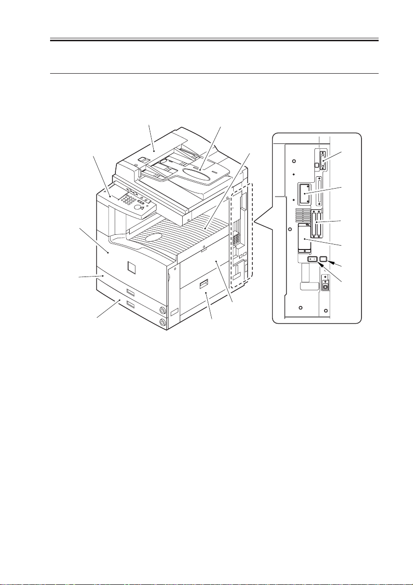
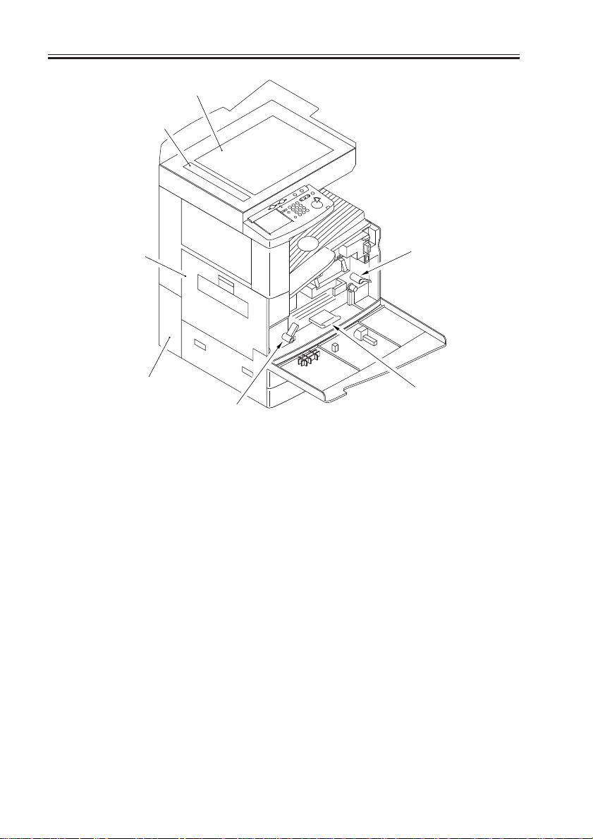
2 Names of Parts
2.1 External View
CHAPTER 1 GENERAL DESCRIPTION
[3]
[4]
[5]
[6]
[1] ADF
[2] Original tray
[3] Control panel
[4] Front cover
[5] Cassette 1
[6] Cassette 2
[7] Delivery tray
[8] Multifeeder
[1]
[2]
[7]
[8]
[9]
[9] Right lower cover
[10] DIMM ROM replacement cover
[11] Network card slot
[12] Parallel connector
[13] Extension board slot
[14] Main power switch
[15] Cassette heater switch
[12]
[11]
[13]
[10]
[15]
[14]
COPYRIGHT
©
F01-201-01
2001 CANON INC. 2000 2000 2000 2000 CANON iR2200/iR2800/iR3300 REV.0 MAR. 2001
1-9 S
CHAPTER 1 GENERAL DESCRIPTION
[1]
[2]
[3]
[4]
[6]
[1] Copyboard glass
[2] DADF reading glass
[3] Left cover
[4] Left lower rear cover (waste toner
case cover)
[5]
[7]
[5] Developing assembly releasing
lever
[6] Feeding assembly releasing lever
[7] Duplex feeding assembly releas-
ing lever
F01-201-02
1-10 S
COPYRIGHT
©
2001 CANON INC. 2000 2000 2000 2000 CANON iR2200/iR2800/iR3300 REV.0 MAR. 2001
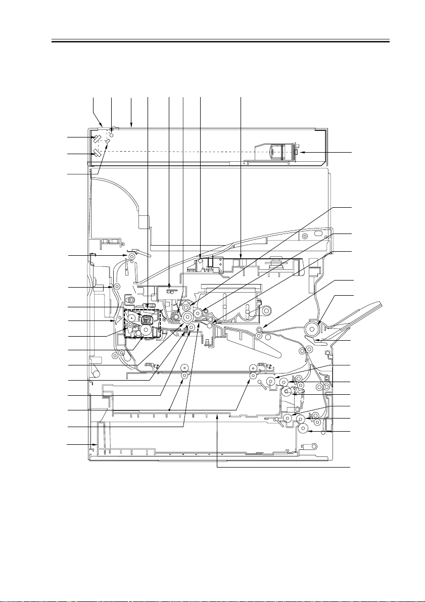
2.2 Cross Section
[1] [5] [7] [9] [11][12][8] [10]
[3]
[4]
[2]
CHAPTER 1 GENERAL DESCRIPTION
[6]
[13]
[15]
[35]
[34]
[30]
[37]
[33]
[31]
[14]
[21]
[20]
[36]
[16]
[23]
[32]
[19]
[17]
[18]
[24]
[25]
[26]
[27]
[28]
[29]
[22]
F01-202-01
COPYRIGHT
©
2001 CANON INC. 2000 2000 2000 2000 CANON iR2200/iR2800/iR3300 REV.0 MAR. 2001
1-11 S

CHAPTER 1 GENERAL DESCRIPTION
[1] DADF reading glass
[2] No. 1 mirror
[3] No. 2 mirror
[4] No. 3 mirror
[5] Scanning lamp
[6] CCD unit
[7] Copyboard glass
[8] Fixing assembly
[9] Pre-exporsure lump
[10] Laser unit
[11] Laser mirror
[12] Drum cleaner assembly
[13] Primary charging assembly
[14] Photosensitive drum
[15] Developing cylinder
[16] Transfer guide
[17] Multifeeder pickup roller
[18] Multifeeder separation pad
[19] Registration roller
[20] Transfer roller
[21] Static eliminator
[22] Cassette 1
[23] Cassette 2
[24] Cassette 1 pickup roller
[25] Cassette 1 feeding roller
[26] Cassette 1 separation roller
[27] Cassette 2 pickup roller
[28] Cassette 2 feeding roller
[29] Cassette 2 separation roller
[30] Fixing film
[31] Lower fixing roller
[32] Pre-transfer roller
[33] Fixing delivery roller
[34] Outside delivery roller
[35] Delivery roller
[36] Duplexing roller
[37] Reversing frapper
T01-202-01
1-12 S
COPYRIGHT
©
2001 CANON INC. 2000 2000 2000 2000 CANON iR2200/iR2800/iR3300 REV.0 MAR. 2001
CHAPTER 1 GENERAL DESCRIPTION
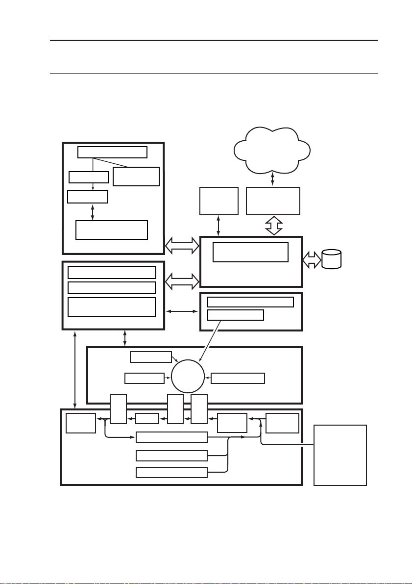
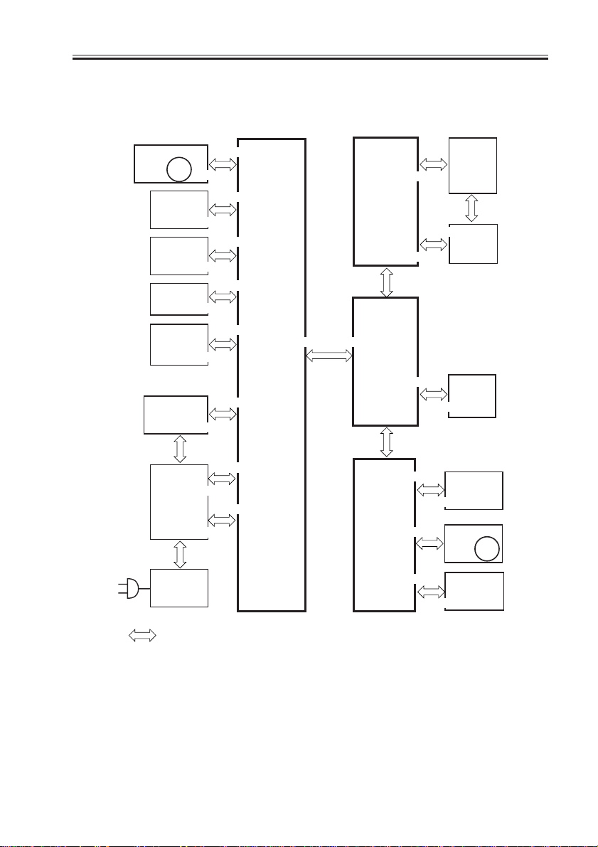
3 System Configuration
3.1 Functional Constr uction
The machine may be broadly divided into the following six functional blocks:
Various
Original
Optical path
CCD PCB
Reader controller
Original Exposure Block
DC controller PCB
Main power supply PCB
Conposit power supply
Original
illumination
PCB
PCB
Control Block
Control
panel
Laser scanner
networks or public
telephone
network
Various
accessory
boards
Main controller PCB
System control/
Image Processing Block
Laser driver PCB
Exposure Block
Laser
HDD
Delivery
tray
COPYRIGHT
©
Charging
Photo-
Cleaning
Feeding
Fixing
Duplexing assembly
sensitive
drum
Separation
Cassette 1
Cassette 2
Development
Image Formation Block
Pickup
Transfer
control
Pickup/Feeding Block
Multi-
feeder
F01-301-01
2001 CANON INC. 2000 2000 2000 2000 CANON iR2200/iR2800/iR3300 REV.0 MAR. 2001
Side paper
deck
(accessory)
1-13 S
CHAPTER 1 GENERAL DESCRIPTION
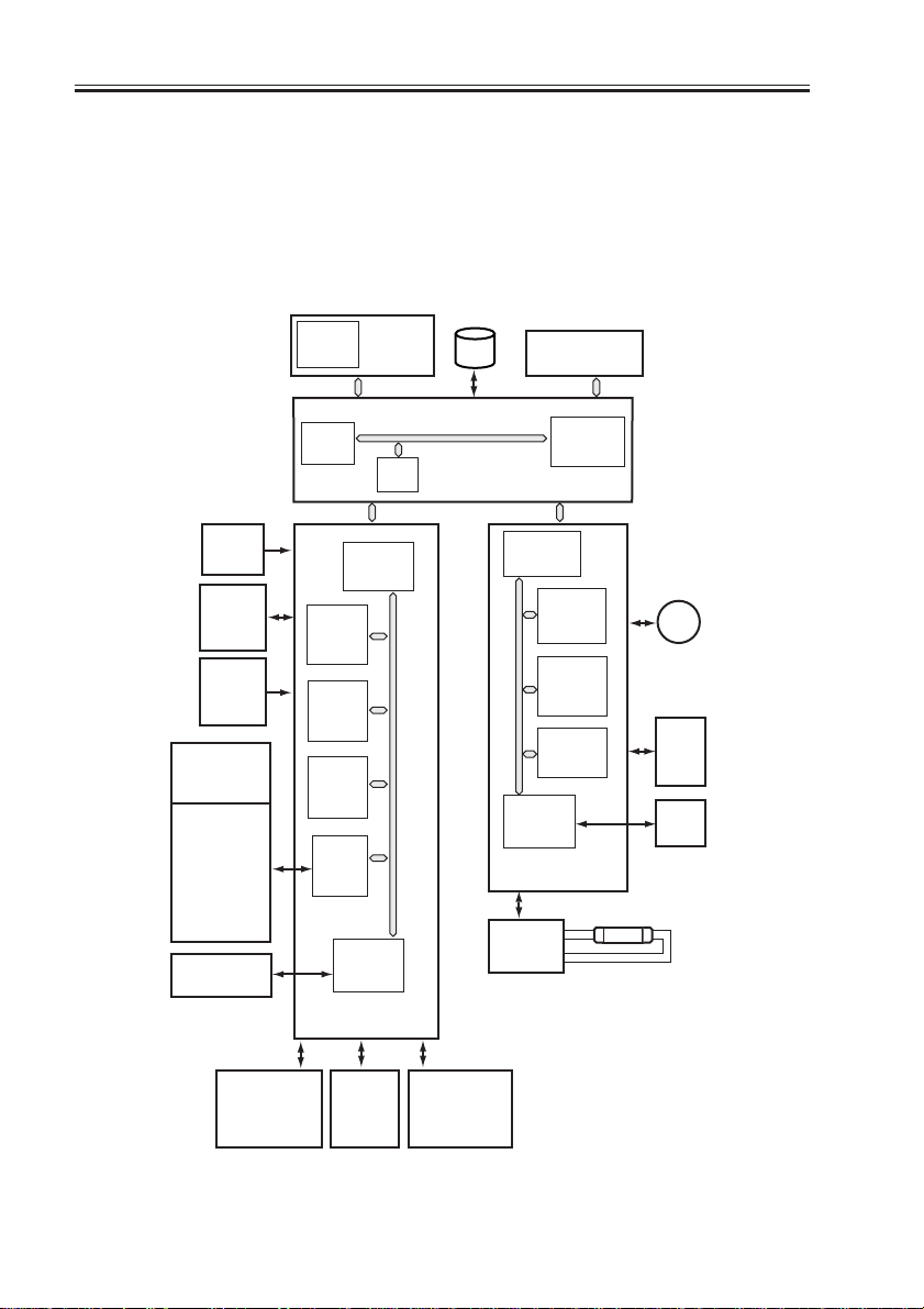
3.2 Outline of the Electr ical Circuitr y
3.2.1 Construction of the Electrical Circuit
The major electrical mechanisms of the machine are controlled by the following PCBs:
[1] Man controller PCB; controls the system as a whole, processes images
[2] DC controller PCB; controls the printer unit, controls the finisher communication
[3] Reader controller PCB; controls the reader unit, controls the DADF communication
BD
PCB
Laser
drive
PCB
Drum
sensor
PCB
Pickup
PCB
DC loads
• Clutch
• Solenoid
• Motor
• Sensor
• Fan
• Etc.
Finisher
(accessory)
CPU
(IC6501)
DIMM
ROM
CPU
(IC300)
SRAM
(IC302)
ROM
(IC301)
GATE
ARRAY
(IC334)
PIO
(IC303)
IPC
(IC309)
DC controller
PCB
Control
panel
PCB
RAM
HDD
Accessory
boards
CPU
(IC1010)
Main controller PCB
CPU
(IC400)
ROM
(IC401)
RAM
(IC402)
EEPROM
(IC403)
IPC
(IC404)
Reader
controller PCB
Inverter
PCB
M400
Scanner
motor
CCD
PCB
ADF
LAMP1
1-14 S
Accessories
power
supply
PCB
COPYRIGHT
©
Main
power
supply
PCB
Composite
power
supply
PCB
F01-302-01
2001 CANON INC. 2000 2000 2000 2000 CANON iR2200/iR2800/iR3300 REV.0 MAR. 2001
CHAPTER 1 GENERAL DESCRIPTION
3.3 Inputs to and Outputs from the Major PCBs
3.3.1 Wiring Diagram of the Major PCBs
Laser scanner
motor
M10
Laser
driver
PCB
BD
PCB
Feed
PCB
Drum
sensor
PCB
Conposit
power supply
PCB
J111
J201
Main
power
supply
PCB
J3128
J500/501
J3129
J1601
J3114
J136
J205
J204
J6
J312
J307/310
J312
J302
J311
J301
J308
J300
DC
controller
PCB
J1015J316
Control
panel
CPU PCB
Main
controller
PCB
J403/407/408
Reader
controller
PCB
J3
J803
J801
J1012
J1025
J1014
J409
J401
LCD
panel
(LCD)
J24
Inverter
HDD
J2005
CCD PCB
J600/601/602
Scanner
motor
J25
PCB
M400
Switch
PCB
J402
J4021
Inverter
PCB
Note: The in the diagram indicates connection between PCBs, NOT the flow of signals.
F01-303-01
COPYRIGHT
©
2001 CANON INC. 2000 2000 2000 2000 CANON iR2200/iR2800/iR3300 REV.0 MAR. 2001
1-15 S
CHAPTER 1 GENERAL DESCRIPTION
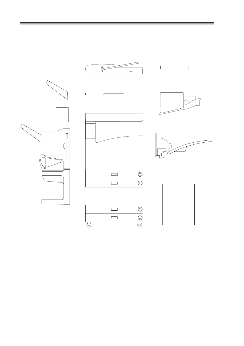
3.4 Configuration with Accessor ies
3.4.1 Accessories for Original/Paper Feeding
[5]
[4]
[6]
[1]
[2]
[10]
[3]
[7]
[8]
[9]
[1] DADF-H1
[2] Platen Cover TypeE
[3] Document Tray-D2
[4] Copy Tray-F1
[5] Saddle Finisher-G1
1-16 S
COPYRIGHT
[6] Puncher Unit-K1/G1/H1
[7] Finisher-J1
[8] Inner 2way Tray-A1
[9] Paper Deck-L1
[10] Cassette Feeding Unit-W1
F01-304-01
©
2001 CANON INC. 2000 2000 2000 2000 CANON iR2200/iR2800/iR3300 REV.0 MAR. 2001
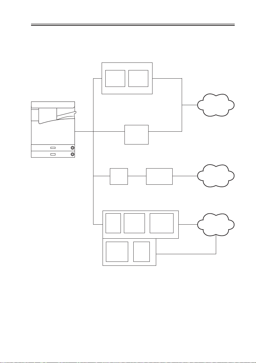
3.4.2 Accessory Boards
CHAPTER 1 GENERAL DESCRIPTION
Network Multi-PDL
Printer Kit-C1
Boot
ROM
Network
PCB
Ethernet Interface
Adapter iN-E3
Network
PCB
Network Interface
Riser Board-A1
Adapter iN-TR2
Riser
PCB
Super G3 FAX Board-J1
PSEUDO
FAX
UNIT
MODEM
PCB
CI
UNIT
NCU
PCB
Token Ring
TokenRing
PCB
SPEAKER
UNIT
Ethernet
network
TokenRing
network
Public
telephone
network
COPYRIGHT
©
Super G3 FAX Expansion Kit-B1
F01-304-02
2001 CANON INC. 2000 2000 2000 2000 CANON iR2200/iR2800/iR3300 REV.0 MAR. 2001
1-17 S

CHAPTER 2
MAIN CONTROLLER
COPYRIGHT
©
2001 CANON INC. 2000 2000 2000 2000 CANON iR2200/iR2800/iR3300 REV.0 MAR. 2001

CHAPTER 2 MAIN CONTROLLER
1 Basic Construction
1.1 Functional Constr uction
The machine may broadly be divided in to the following functional blocks, with the con-
troller block covering the shaded area:
Reader unit
Control panel
Controller unit
Main controller PCB
Printer unit
F02-101-01
Accessory
boards
HDD
COPYRIGHT
©
2001 CANON INC. 2000 2000 2000 2000 CANON iR2200/iR2800/iR3300 REV.0 MAR. 2001
2-1 S

CHAPTER 2 MAIN CONTROLLER
1.2 Outline of the Electr ical Circuitr y
1.2.1 Outline
The major electrical mechanisms of the controller block are controlled by the CPU on the
main controller PCB. The CPU, RAM, DIMM, and the ICs and HDD around the CPU have
the following functions:
1.2.2 Main Controller PCB
Name Description
CPU • Controls the processing of image data from the reader unit.
• Controls the processing of image data to the printer unit.
• Controls the HDD.
• Controls the interface of the following: network, DMA controller, PCI,
and ROM/RAM.
RAM • Stores program data and image data temporarily.
DIMM-ROM • Stores the system control program.
• Stores the boot program.
T02-102-01
1.2.3 HDD
Item Description
HDD • Sores the system software.
• Stores image data for the Box function.
2-2 S
COPYRIGHT
©
T02-102-02
2001 CANON INC. 2000 2000 2000 2000 CANON iR2200/iR2800/iR3300 REV.0 MAR. 2001

Reader unit
CHAPTER 2 MAIN CONTROLLER
Control panel
CPU
DIMM-ROM
RAM
Main controller PCB
Printer unit
F02-102-01
CPU
Accessory
boards
HDD
COPYRIGHT
©
2001 CANON INC. 2000 2000 2000 2000 CANON iR2200/iR2800/iR3300 REV.0 MAR. 2001
2-3 S

CHAPTER 2 MAIN CONTROLLER
1.3 Star t-Up Sequence
1.3.1 Outline
The system software used to control the machine is stored on the machine’s HDD. The
CPU on the main controller PCB reads the system software from the HDD into the SDRAM
fitted to the DIMM socket of the main controller PCB.The control panel displays the following screen while the CPU reads the system software from the HDD to the SDRAM, and the
progressive bar on the screen indicates the progress of the start-up sequence.
Start-Up Screen
Wait…
2-4 S
COPYRIGHT
©
Progressive bar
F02-103-01
2001 CANON INC. 2000 2000 2000 2000 CANON iR2200/iR2800/iR3300 REV.0 MAR. 2001

CHAPTER 2 MAIN CONTROLLER
1.3.2 Start-Up Sequence
When the main power switch is tuned on, the CPU on the main controller CPU executes
the self-diagnostic program stored in the boot ROM.
The self-diagnostic program checks the condition of the SDRAM and the HDD; upon de-
tection of a fault, it will indicate the fact in the control panel in the form of an error
code.
SDRAM
System
area
Image data
area
CPU
HDD
COPYRIGHT
©
Self-diagnostic
program
Boot ROM
Main controller PCB
access to the program during execution
Boot
program
F02-103-02
E601-0000, 0001
Indicates the presence of an error in image transfer information.
E602-0001, 0002
Indicates the presence of an error in write/read operation.
2001 CANON INC. 2000 2000 2000 2000 CANON iR2200/iR2800/iR3300 REV.0 MAR. 2001
2-5 S

CHAPTER 2 MAIN CONTROLLER
When the self-diagnostic program ends normally, the boot program also stored in the boot
ROM will start up. The boot program reads the system software from the HDD into the system area of the SDRAM.
When the write operation ends, the system software in the SDRAM starts up to initialize
the various parts of the machine, at the end of which the control panel will indicate the normal operation screen and, at the same time, the Start key LED changes from red to green to
indicate that the machine is ready to accept a job.
The machine’s system software consists of multiple modules, and those modules that are
needed for a specific task in question will be called into the system area of the SDRAM for
use.
SDRAM
System
area
Image data
area
CPU
HDD
2-6 S
COPYRIGHT
©
Self-diagnostic
program
Boot ROM
Main controller PCB
:
access to the program during execution.
:
flow of the system program.
Boot
program
F02-103-03
2001 CANON INC. 2000 2000 2000 2000 CANON iR2200/iR2800/iR3300 REV.0 MAR. 2001

CHAPTER 2 MAIN CONTROLLER
2 Digital Image Processing
2.1 Outline
The machine’s digital image processing and image memory are controlled by the main
controller PCB. The following is a block diagram of digital image processing:
Reader PG
Main controller unit
Density conversion
(LUT)
Binary processing
(error diffusion method)
(text, text/photo, print photo)
Binary-binary processing density conversion
Enlargement/reduction
(main scanning direction)
Intensity/density conversion
Density adjustment
(F value conversion)
1
Printer PG
Reader unit
8
8
Edge emphasis
8
Editing
8
(LOG conversion)
8
8
Density correction
(γ conversion)
8
Binary processing
(dither screen method)
Image memory
control
1
1
Image data after
shading
(film photo)
1
Compression/de-compression,
rotation, enlargement/reduction
SDRAM
I/O control
HDD
Image server
COPYRIGHT
©
Smoothing
4 or 2
Printer unit
F02-201-01
2001 CANON INC. 2000 2000 2000 2000 CANON iR2200/iR2800/iR3300 REV.0 MAR. 2001
2-7 S

CHAPTER 2 MAIN CONTROLLER
2.2 Input Image Processing
The image data from the reader unit is processed for the following:
2.2.1 Image Data from the Reader Unit
The image signals from the reader unit are 8-bit, 256-gradation intensity image signals
which have been subjected to shading correction.
The signals arrive from two signal lines (for even- and odd-numbered pixels).
2.2.2 Enlargement/Reduction (main scanning direction)
An image is enlarged or reduced by processing image data when writing it into or reading
it from image memory.
2.2.3 Edge Emphasis
For each mode (text, text/photo, print photo, film photo), edge emphasis is executed so as
to increase sharpness while suppressing moire.
2.2.4 Editing
The machine provides various editing functions: negative/positive reversal, mirror, fold.
2.2.5 Density Conversion (LUT)
In this block, the intensity image signals are converted into density image signals, and
processing is executed so as to enable the best output density curve for a specific mode in
question.
a. LOG Conversion
Using a LOG conversion table, intensity image signals based on reflected light are converted into density image signals based on density data.
b. Density Adjustment (F-value conversion)
The F-value table most suited to the setting of the Density key in the control panel is used
to adjust the density; it, however, will not be executed in memory copy mode.
c. Density Correction (
The γ conversion table best suited to each specific mode (test, text/photo, print photo, film
photo) is used to correct density.
γγ
γ conversion)
γγ
2-8 S
COPYRIGHT
©
2001 CANON INC. 2000 2000 2000 2000 CANON iR2200/iR2800/iR3300 REV.0 MAR. 2001

CHAPTER 2 MAIN CONTROLLER
2.2.6 Binary Processing (error diffusion method T-BIC)
In the error diffusion method (T-BIC), the texture is controlled to process the data for optimum printing effects; 8-bit image density signals of each mode (text, text/photo, print
photo) are converted into 1-bit image density signals (binary).
2.2.7 Binary (dither screen method)
In the dither screen method, the texture is controlled to process the data for optimum
printing effects; 8-bit image density signals for film photo mode are converted into 1-bit image density signals (binary).
Although expressed in binary, the resulting signals enable reproduction in 256 gradations
(dither screening of 40×40 pixels).
2.3 Image Memor y Control
The image data after binary processing is controlled for the following:
2.3.1 Compression/De-Compression, Rotation, and Enlargement/Reduc-
tion
The binary data generated as the result of the foregoing processes is subjected to the following: compression/de-compression (for electronic sorting), rotation, resolution conversion.
2.3.2 SDRAM
The image data subjected to image memory control is temporarily stored in SDRAM.
2.3.3 HDD
The HDD functioning as an image server is used to store image data for the Box function.
COPYRIGHT
©
2001 CANON INC. 2000 2000 2000 2000 CANON iR2200/iR2800/iR3300 REV.0 MAR. 2001
2-9 S

CHAPTER 2 MAIN CONTROLLER
2.4 Output Image Processing
The output image data to the printer unit is subjected to the following processing:
2.4.1 Smoothing
a. When Generating Read Images
In the case of text or test/photo mode, the input image of 600×600 dpi is converted into
1200*×600 dpi by means of smoothing.
*Equivalent.
In smoothing, image data is compared against a template consisting of several combina-
tions of pattern matrixes for replacement of selected pixels.
In addition, notch processing is also executed at the same time as a pattern unique to read
image.
b. When Generating Printer (PDL) Images
The image data is subjected to the type of smoothing best suited to PDL, in which
600×600 dpi is converted into 2400*×600 dpi.
*Equivalent.
2.4.2 Binary-Binary Density Conversion (read image output only)
This processing is used as an auxiliary means for adjusting the density of images.
2-10 S
COPYRIGHT
©
2001 CANON INC. 2000 2000 2000 2000 CANON iR2200/iR2800/iR3300 REV.0 MAR. 2001

CHAPTER 2 MAIN CONTROLLER
3 Soft Counters
The machine is equipped with soft counters that count the number of prints it has
handled; the counter readings may be checked by pressing the Check key in the control
panel.
The counters are controlled by the main controller PCB, and each count is incremented
when any of the following sensors detects paper during copy/print operation:
When No Delivery Option Is Installed
Copy/print operation Sensor used Delivery slot
Single-sided PS15 No. 1 delivery sensor Below the inside tray
Double-sided 1st side PS18 Duplexing unit outlet sensor
2nd side PS15 No. 1 delivery sensor Below the inside tray
When the Inner 2-Way Tray Is Used
Copy/print operation Sensor used Delivery slot
Single-sided PS19S No. 2 delivery sensor Above the inside tray
PS21S No. 3 delivery sensor Outside tray
PS18 Duplexing unit outlet sensor
Double-sided 1st side PS19S No. 2 delivery sensor Above the inside tray
2nd side PS21S No. 3 delivery sensor Above the inside tray
2nd side PS21S No. 3 delivery sensor Outside tray
When a Finisher Is Installed
Copy/print operation Sensor used Delivery slot
Single-sided S2 Inlet sensor Finisher delivery tray
Double-sided 1st side PS18 Double-sided outlet sensor
2nd side S2 Inlet sensor Finisher delivery tray
When Delivery Is to the Saddle finisher
Copy/print operation Sensor used Delivery slot
Single-sided PI1 Inlet sensor Finisher delivery tray
Double-sided 1st side PS18 Double-sided outlet sensor
2nd side PI1 Inlet sensor Finisher delivery tray
T02-301-01
COPYRIGHT
©
2001 CANON INC. 2000 2000 2000 2000 CANON iR2200/iR2800/iR3300 REV.0 MAR. 2001
2-11 S

CHAPTER 2 MAIN CONTROLLER
The following diagrams show the locations of the sensor in the finisher and the saddle fin-
isher:
Inlet sensor(S2)
F02-301-01
Inlet sensor (PI1)
2-12 S
COPYRIGHT
©
F02-301-02
2001 CANON INC. 2000 2000 2000 2000 CANON iR2200/iR2800/iR3300 REV.0 MAR. 2001

CHAPTER 2 MAIN CONTROLLER
The counters possess a total of 16 modes, consisting of eight modes for large-size papers
and eight modes for small-size papers; the following shows the basic counter modes:
Copy/print mode Large-size Small-size*
Local copy A B
PDL print C D
Box print E F
Remote copy print G H
Fax receive print I J
Report print K L
Double-sided print M N
Scan O P
*At time of shipment, B4 or smaller; may be changed in service mode to count B4 as large-size.
T02-301-02
The following shows the counter configurations according to mode at time of shipment:
Counter Description*1 Default display Default switch *2
100V model 120/230V model
Counter 1 Total (A through L) ON ON Fi xed
Counter 2 Total large (ACEGIK) OFF ON May be changed.
Counter 3 Copy 1 (ABGH) OFF ON May be changed.
Counter 4 Copy 1 large (AG) OFF ON May be changed.
Counter 5 Print 1 total (CDEF) OFF OFF May be changed.
Counter 6 Fax total (IJ) OFF OFF May be changed.
*1:The notations in the parentheses indicate the corresponding basic counter modes (T02-300-20).
*2:The counter description may be changed or enabled/disabled for display in service mode (except
counter 1, whose setting cannot be cannot be changed).
T02-301-03
COPYRIGHT
©
2001 CANON INC. 2000 2000 2000 2000 CANON iR2200/iR2800/iR3300 REV.0 MAR. 2001
2-13 S

CHAPTER 2 MAIN CONTROLLER
OPTION>USER>COUNTER1
Use it to enable/disable the display of soft counter 1 in the control panel.
OPTION>USER>COUNTER2
Use it to enable/disable the display of soft counter 2 in the control panel, or
to change the counter type.
OPTION>USER>COUNTER3
Use it to enable/disable the display of soft counter 3 in the control panel, or
to change the counter type.
OPTION>USER>COUNTER4
Use it to enable/disable the display of soft counter 4 in the control panel, or
to change the counter type.
OPTION>USER>COUNTER5
Use it to enable/disable the display of soft counter 5 in the control panel, or
to change the counter type.
OPTION>USER>COUNTER6
Use it to enable or disable the display of soft counter 6 in the control panel,
or to change the counter type.
2-14 S
COPYRIGHT
©
2001 CANON INC. 2000 2000 2000 2000 CANON iR2200/iR2800/iR3300 REV.0 MAR. 2001

CHAPTER 2 MAIN CONTROLLER
4 Controlling the Power Supply
4.1 Outline
In addition to its control in response to the operation of the main power switch, the main
controller PCB possesses the following control mechanisms in relation to the power supply:
• Standby mode (normal operation)
• Sleep mode 1
• Sleep mode 2
4.2 Power Supply Modes
The machine has the following modes for each of its power supply mechanisms; +3.3V
all-night (3.3 VB), +3.3V non-all night (3.3 VA), +5V, and 24V:
Mode +3.3V all night +3.3V non-all night +5V +24V LCD
Standby Yes Yes Yes Yes Yes
Sleep mode 1 Yes Yes Yes Yes No
Sleep mode 2 Yes No No No No
T02-402-01
4.3 Standby Mode (nor mal operation)
In standby mode, the machine is in operation or is ready operate, and nearly all components are supplied with power; not only the main controller PCB, but also the reader unit,
printer unit, and control panel are all ready for communication and control.
4.4 Sleep Mode 1
In sleep mode 1, only the LCD image desplay remains OFF.
COPYRIGHT
©
2001 CANON INC. 2000 2000 2000 2000 CANON iR2200/iR2800/iR3300 REV.0 MAR. 2001
2-15 S

CHAPTER 2 MAIN CONTROLLER
4.4.1 Shift from Standby Mode to Sleep Mode 1
A shift from standby mode to sleep mode 1 is executed for the following:
• The power switch (soft switch) in the control panel is OFF.
• The machine remains in standby mode and a specific period of time (may be changed in
user mode) has passed.
In addition, the following must be true:
• The setting of 'Function key wakeup ON/OFF' under 'Common settings' in user mode is
set to 'ON'.
• The setting of 'Energy consumption in Sleep Mode' under 'Common settings' in user
mode is set to 'high'.
• The setting of 'NetWare settings' under 'Network settings' in user mode is set to 'ON'.
• The setting of 'AppleTalk settings' under 'Network settings' in user mode is set to ON'.
• The setting of 'DHCP' under 'IP Address / TCP/IP settings' in user mode is set to use.
• A TokenRing board is installed.
• In the fax, timer transmission is selected.
• In the fax, an auto start job is selected.
• An extension of the fax is in use (engaged).
4.4.2 Shift from Sleep Mode 1 to Standby Mode
A shift from sleep mode 1 to standby mode is expected for the following:
• The power switch (soft switch) in the control panel is turned on.
2-16 S
COPYRIGHT
©
2001 CANON INC. 2000 2000 2000 2000 CANON iR2200/iR2800/iR3300 REV.0 MAR. 2001

CHAPTER 2 MAIN CONTROLLER
4.5 Sleep Mode 2
In sleep mode 2, only the +3.3V all-night (3.3 VB) power supply is ON. The CPU on the
main control paper remains in wait for an interrupt (keeping the program at rest) to limit the
consumption of power.
4.5.1 Shift from Standby Mode to Sleep Mode 2
A shift from standby mode to sleep mode 2 is executed under the following:
• The power switch (soft switch) in the control panel is OFF.
• The machine has remained in standby mode for a specific period of time (may be
changed in user mode).
4.5.2 Shift from Sleep Mode 2 to Standby Mode
A shift from sleep mode 2 to standby mode is executed for the following:
• The power switch (soft switch ) in the control panel is ON.
4.5.3 Shift from Sleep Mode 2 to Sleep Mode 1
A shift from sleep mode 2 to sleep mode 1 is executed for the following:
• PDL data is received from the network or from the parallel port.
4.6 Tur ning Off the Power
The power is turned off when the main power switch is turned off. A shift from this sta te
may be made only by turning on the main power switch; the shift will be automatic and to
standby mode.
COPYRIGHT
©
2001 CANON INC. 2000 2000 2000 2000 CANON iR2200/iR2800/iR3300 REV.0 MAR. 2001
2-17 S

CHAPTER 2 MAIN CONTROLLER
5 New Functions
5.1 Hard Disk Spool
In hard disk spool, print data is not directly sent to memory for printing, but spooled on
the HDD before printing, thus releasing the application program running on the host PC
sooner than otherwise.
When this function is used, a print job from the PC is stored in the spool area of the
HDD. (The spool area is as large as about 300 MB.) Once spooled, the jobs are then sent to
the RIP processing block in the order they have been received.
The jobs are removed from the spool as they are printed, and as many as 100 jobs may be
spooled at a time.
The following diagram shows the flow of data, from spooling on the HDD to execution:
HDD
Spool area
job 1
job 2
job n
Network PCB
(1)
PDL data
Print
buffer
area
(3)
(7)
(8)
Binary data
(2)
PDL data
PDL data
Binary data
F02-501-01
Main controller PCB
(4)
RIP
processing
block
(6)
Compression data
(9)
Page
memory
for printing
(11)
(10)
Binary data
(12)
Image date
Image data
(5)
Image data
Binary data
Binary data
Print image
processing block
Printer unit
Memory for
development
Compression
circuit
De-compression
circuit
2-18 S
COPYRIGHT
©
2001 CANON INC. 2000 2000 2000 2000 CANON iR2200/iR2800/iR3300 REV.0 MAR. 2001

CHAPTER 2 MAIN CONTROLLER
5.2 SMB Pr inting
SMB has been developed so as to use NetBIOS, which specifies an address by means of a
computer name, for use solely with a specific protocol. SMB over TCP/IP is designed for
use in combination with the TCP/IP protocol, enabling the machine to print data directly
from Windows 95/98/ME without going through a Windows NT/2000 sever as is in the case
of LPR printing and without the need for an LPR utility. (A Windows work group may be
made use of, but Windows NT/2000 cannot be called into the domain.)
On a TCP/IP network an address must be specified by means of an IP address, not the
name of the computer in question, requiring conversion of a computer name into an IP address. If a WINS (Windows Internet Name Service) server exits on the network, the function
may also be made use of. If it does not exist or is not used, the PC will contact all devices
on the network to find out the IP address of the machine before it sends a print job to the
machine.
WINS server
Windows 95/98
COPYRIGHT
©
Ethernet
Protocol:TCP/IP
Service:SMB
Windows 95/98Windows 95/98
F02-502-01
2001 CANON INC. 2000 2000 2000 2000 CANON iR2200/iR2800/iR3300 REV.0 MAR. 2001
iR2200
iR2800
iR3300
2-19 S

CHAPTER 2 MAIN CONTROLLER
5.3 LPD Banner
When OPD printing is selected, the following job information will be printed:
LPD Banner (sample)
iR2200-3300 (iN-E2)
USER NAME : ts
HOST NAME : canon
JOB NAME : golfer.ps
F02-503-01
2-20 S
COPYRIGHT
©
2001 CANON INC. 2000 2000 2000 2000 CANON iR2200/iR2800/iR3300 REV.0 MAR. 2001

CHAPTER 3
INSTALLATION
COPYRIGHT
©
2001 CANON INC. 2000 2000 2000 2000 CANON iR2200/iR2800/iR3300 REV.0 MAR. 2001

CHAPTER 3 INSTALLATION
1 Selecting the Site of Installation
Select the site of installation against the following conditions; if possible, visit the user’s
in advance of the delivery of the machine:
1. There must be a power outlet that may be used exclusively for the machine and rated as
indicated (±10%).
2. The temperature of the room must be between 7.5° and 30°C (59° and 86°F) and humid-
ity, between 5% and 80%. Avoid areas near a water faucet, water boiler, humidifier, or
refrigerator.
3. The site must not be near a source of fire or must not be subject to dust or ammonium
gas. If the site is exposed to direct rays of the sun, provide curtains.
4. The level of ozone generated by the machine in operation will not affect the health of
the individuals around it. Nevertheless, some may find the odor unpleasant, requir ing
good ventilation of the work place.
5. The floor of the site must be level so that the feet of the machine will remain in contact
and the machine itself will remain level.
COPYRIGHT
©
2001 CANON INC. 2000 2000 2000 2000 CANON iR2200/iR2800/iR3300 REV.0 MAR. 2001
3-1 S

CHAPTER 3 INSTALLATION
6. The site must be such that the machine will be at least 10 cm away from any wall, allowing adequate space for work.
10 cm min.
50 cm min.50 cm min.
50 cm min.
F03-100-01
10 cm min.
110 cm min.
50 cm min.
100 cm min.
F03-100-02
7. The site must be well ventilated. Do not install the machine near the air inlet of the
room.
3-2 S
COPYRIGHT
©
2001 CANON INC. 2000 2000 2000 2000 CANON iR2200/iR2800/iR3300 REV.0 MAR. 2001

2 Unpacking and Installation
2.1 Before Star ting the Work
Keep the following in mind for the work:
1. If the machine is brought in from a cold to warm place, its pickup/feeding assembly can develop condensation, leading to image faults. Leave
the machine alone for at least one hour, and start the work after the machine has become used to the room temperature.
The term condensation refers to the symptom that occurs when a piece of
metal is brought in from a cold to warm place, cooling the vapor in the
air rapidly and turning it into droplets of water on the metal surface.
2. The machine weighs about 80 kg. Be sure to work in a group of four.
CHAPTER 3 INSTALLATION
COPYRIGHT
©
2001 CANON INC. 2000 2000 2000 2000 CANON iR2200/iR2800/iR3300 REV.0 MAR. 2001
3-3 S

CHAPTER 3 INSTALLATION
2.2 Unpacking and Removing the Fixing Materials
Work Checks/remarks
1) Open the shipping box, and remove the
plastic sheets.
• If you are installing the pedestal at the
same time, unpack it.
2) While working in a group of four, hold
the grips [1], and place it on the pedestal. (weight of body: about 80kg)
Take care so that the main
power switch will not be turned
on when the machine is lifted.
[1]
3-4 S
COPYRIGHT
©
[1]
2001 CANON INC. 2000 2000 2000 2000 CANON iR2200/iR2800/iR3300 REV.0 MAR. 2001

CHAPTER 3 INSTALLATION
Work Checks/remarks
3) Remove the packing tape of the ma-
[1]
chine.
4) Press the cassette release button, and
take out each cassette to the front.
5) Connect the machine and the pedestal
using a screw [1].
Other types of pedestal may
also be connected using a screw.
6) Slide the cassettes into the machine.
7) Open the cardboard box that comes
with the machine, and take out the components and attachments; check to make sure that none of the fol-
lowing is missing:
• User’s Manual
• Drum unit
• Right lower cover
• Cassette size label (inside cassettes)
• Cassette size plate (inside cassette)
• Guidebook (model w/ printer function
only)
• CD-ROM (model w/ printer function
only)
COPYRIGHT
©
2001 CANON INC. 2000 2000 2000 2000 CANON iR2200/iR2800/iR3300 REV.0 MAR. 2001
3-5 S

CHAPTER 3 INSTALLATION
2.3 Mounting the Scanner
Work Checks/remarks
1) Remove the screw [1] and the tag [2]
used to hold the scanner in place on the
left cover of the reader unit.
Keep the screw stored away for
possible relocation of the machine.
2.4 Removing the Dummy Drum
Work Checks/remarks
[2]
[1]
1) Open the front cover.
2) Shift down the feeder releasing lever [1]
to release the feeding assembly.
3) Turn the developing assembly locking
lever [2] counterclockwise to free the
developing assembly.
3-6 S
COPYRIGHT
©
2001 CANON INC. 2000 2000 2000 2000 CANON iR2200/iR2800/iR3300 REV.0 MAR. 2001
[2]
[1]

CHAPTER 3 INSTALLATION
Work Checks/remarks
4) Remove the fixing screw [1] from the
dummy drum.
• The removed fixing screw will be used
when mounting the drum unit.
5) Pull the dummy drum [2] straight out to
the font.
• The removed dummy drum will no
longer be used.
2.5 Supplying the Toner
Work Checks/remarks
1) Holding the grip [1] of the developing
assembly, pull the developing assembly
[2] to the front until it stops.
[2]
[1]
[2]
COPYRIGHT
©
[1]
2001 CANON INC. 2000 2000 2000 2000 CANON iR2200/iR2800/iR3300 REV.0 MAR. 2001
3-7 S

CHAPTER 3 INSTALLATION
Work Checks/remarks
2) Shake the toner cartridge [1] several
items.
3) Set the toner cartridge to the developing
assembly, and push it down until the
opening tab [2] springs to view.
• The toner cartridge is locked to the developing assembly.
4) While lightly holding down the toner
cartridge with one hand, pull the open
tab to the front until it stops (where the
marking STOP is found).
5) Tap lightly on the top of the toner cartridge so that all toner will drop.
[1]
[2]
3-8 S
COPYRIGHT
©
2001 CANON INC. 2000 2000 2000 2000 CANON iR2200/iR2800/iR3300 REV.0 MAR. 2001

Work Checks/remarks
6) Push in the black cover of the developing assembly back to its initial position.
• The toner cartridge will become disengaged.
7) Remove the toner cartridge.
8) Push in the developing assembly until it
butts against the rear.
CHAPTER 3 INSTALLATION
COPYRIGHT
©
2001 CANON INC. 2000 2000 2000 2000 CANON iR2200/iR2800/iR3300 REV.0 MAR. 2001
3-9 S

CHAPTER 3 INSTALLATION
2.6 Mounting the Dr um Unit
Work Checks/remarks
1) Unpack the drum unit, and remove the
two releasing members [1] of the primary charging roller.
Remove all other packing tape and the
like.
1. Do not touch the dump area
of the photosensitive drum to
avoid damage.
2. Take care not to expose the
photosensitive drum to strong
light.
3. Take care not to damage the
stirrups found at the bottom
of the drum unit.
2) Check to make sure that the developing
assembly is released; then, holding the
drum unit [1] by its long hole, slide inside the machine along the rails [2].
At this time, take full care not to bring
the developing assembly in contact with
the developing cylinder, which is situated nearby.
[1]
3-10 S
COPYRIGHT
©
[2]
[1]
2001 CANON INC. 2000 2000 2000 2000 CANON iR2200/iR2800/iR3300 REV.0 MAR. 2001

Work Checks/remarks
3) Using the fixing screw [1] removed
from the dummy drum previously, secure the dump unit [2] in place.
4) Fill out the date label, and attach it to
the front cover of the drum unit.
5) Turn the developing assembly locking
lever clockwise to lock the developing
assembly in place.
6) Shift up the feeding releasing lever to
lock the feeding assembly in place.
CHAPTER 3 INSTALLATION
[2]
[1]
Do not turn on the main power
switch while the feeding assembly remains released; otherwise,
the fixing assembly will be
damaged.
7) Close the front cover.
COPYRIGHT
©
2001 CANON INC. 2000 2000 2000 2000 CANON iR2200/iR2800/iR3300 REV.0 MAR. 2001
3-11 S

CHAPTER 3 INSTALLATION
2.7 Stirr ing the Toner
Work Checks/remarks
1) Connect the power plug to the power
outlet.
2) Turn on the main power switch.
• Wait until the control panel indicates
that the machine is ready for operation.
3) Start service mode.
4) Make the following selections:
COPIER>FUNCTION>INST ALL>TONERS.
5) Press the OK key.
• The stirring operation will last for 240
sec (4 min), after which the operation
stops automatically.
6) Press the Reset key twice to end service
mode.
7) Execute 'roller clean' in user mode ('adjust/clean'), and execute transfer charging roller resistance detection control
(ATVC).
The power supply
must be as rated. (The
voltage may be ±
10% of the rating, but
it must have the rated
amperage.)
Press the key, ‘2’ and ‘8’ at the
same time, and the key once again.
The following message will appear:
“CHECK THE DEVELOPER.” In response, check to see if
the developing assembly is properly locked
in place.
If you inadvertently
stopped stirring of the
toner in the middle, be
sure to execute
‘TONER-S’ once
again.
3-12 S
COPYRIGHT
©
Display
I/O Adjust Option Test
<INSTALL > < 1/ 1 > <NO-PAPER>
TONER-S
STRD-POS
CARD 0 →( 0) { 1 - 2700}
2001 CANON INC. 2000 2000 2000 2000 CANON iR2200/iR2800/iR3300 REV.0 MAR. 2001
Function
Check the Developer
+/- OK
Counter

2.8 Setting the Cassette
Work Checks/remarks
1) Press the cassette releasing button, and
slide out the cassette to the front.
2) Check with the user to find out the size
of paper to use, and check the size setting (A/B or Inch) using the selection
switch [1] of each cassette.
CHAPTER 3 INSTALLATION
COPYRIGHT
©
[1]
2001 CANON INC. 2000 2000 2000 2000 CANON iR2200/iR2800/iR3300 REV.0 MAR. 2001
3-13 S

CHAPTER 3 INSTALLATION
Work Checks/remarks
3) Pick the lever of the side guide plate
and the rear guide plate, and adjust it to
the appropriate paper size index.
The middle cassette cannot hold
A3 or 11×17 paper.
4) Set the paper size dial to suit the selected paper size.
3-14 S
COPYRIGHT
©
Set the dial as indicated.
2001 CANON INC. 2000 2000 2000 2000 CANON iR2200/iR2800/iR3300 REV.0 MAR. 2001

CHAPTER 3 INSTALLATION
Work Checks/remarks
5) Attach the size label [2] to the cassete
size plate [1], and fit the cassette size
plate to each cassette.
6) Put paper into the cassettes [3], and
slide them into the machine.
[1]
[3]
A4
LTR
[2]
COPYRIGHT
©
2001 CANON INC. 2000 2000 2000 2000 CANON iR2200/iR2800/iR3300 REV.0 MAR. 2001
3-15 S

CHAPTER 3 INSTALLATION
2.9 Checking the Images/Operations
Work Checks/remarks
1) To install the machine not using the 2cassette pedestal, mount the right lower
cover [1].
1. Skip this step if the machine
is installed on a 2-cassette
pedestal.
2. After removing the right
lower cover, check to make
sure that the cover is securely
in place.
Optimum Image
2) Clean the surface of the reading glass of
the copyboard.
3) Using the NA-3 Chart as the original,
make a print to check the images and
the operation.
4) Make user mode settings (e.g., date,
time) and service mode settings
(COPIER>OPTION>USER) to suit the
needs of the user.
• In text mode, the white background
• In text/photo mode, step edge No. 10
• In photo mode, the white background
The non-image width must be as indicated: 2.5±1.5 mm.
Checking the Operations
• During copying operation, check to
• During double-sided copying opera-
• For pickup operation, check to make
• There must not be abnormal operating
• Make copies at each default reproduc-
• Make copies in multiple sets, and
[1]
must not be foggy.
must be barely visible. The white
background must be free of fogging.
must be free of fogging. (The moire, if
any, along the step edges and the halftone area does not indicate a fault.)
make sure the operations are normal.
tion, check to make sure that paper is
moved normally in the duplex unit.
sure that pickup from each source of
paper is normal.
noise.
tion ratio, and check to make sure that
the images are normal.
check to make sure that copies are
made specified numbers.
3-16 S
COPYRIGHT
©
2001 CANON INC. 2000 2000 2000 2000 CANON iR2200/iR2800/iR3300 REV.0 MAR. 2001

Work Checks/remarks
5) If necessary in view of the site environment, turn on the cassette heater switch
[1].
6) Move the machine to the site of installation; if it is placed on a pedestal, secure
it in place using the four adjusters.
7) Clean the area around the machine, and
fill out the Service Book.
CHAPTER 3 INSTALLATION
[1]
COPYRIGHT
©
2001 CANON INC. 2000 2000 2000 2000 CANON iR2200/iR2800/iR3300 REV.0 MAR. 2001
3-17 S

CHAPTER 3 INSTALLATION
2.10 Connecting to the Network
Perform the following steps if the machine is equipped with printer functions:
1) Turn off the main power.
2) Connect the network cable to the machine, and turn on the main power.
3) Inform the user’s system administrator that the machine has been installed, and ask him/
her to make the network settings for the machine.
2.11 Checking the Network Connection
Perform the following steps if the machine is equipped with printer functions:
If the user’s network environment is TCP/IP, use the PING function to make sure that the
network PCB has properly been installed and the network settings have properly been made.
If the user’s network environment is IPX/SPX or AppleTalk, on the other hand, these checks
are not needed.
2.11.1 Using the PING Function
1) Make the following selections to select
PING:
COPIER>TEST>PING>NETWORK.
2) Enter the IP address using the keypad
on the control panel, and press the OK
key .
3) Press the Start key.
• If PING is successful, ‘OK’ will be in-
dicated: otherwise, ‘NG’ will be indicated.
PING
<NETWORK>
Results (OK/NG)
< 1/1 >
0 . 0 . 0 . 0
<READY >
IP address input
+/-
OK
3-18 S
COPYRIGHT
©
2001 CANON INC. 2000 2000 2000 2000 CANON iR2200/iR2800/iR3300 REV.0 MAR. 2001

CHAPTER 3 INSTALLATION
2.11.2 Making a Check Using a Remote Host Address
The connection to the network may be checked by executing PING using a remote host
address (i.e., the IP address of a PC terminal connected to and operating on the TCP/IP network to which the machine is connected).
1) Inform the user’s system adminisrator that the network connection will be checked using
PING.
2) Check with the user’s system administrator to find out the remote host address.
3) Enter the remote host address in the PING field.
• If ‘OK’ is indicated, the connection to the network is correct.
• If ‘NG’ is indicated, the connection to the network is not correct; investigate the cause as
follows:
2.12 Troubleshooting the Network
Perform the following steps if the machine is equipped with printer functions:
If the connection to the network is not made, the following can be suspected; perform the
steps under 2.12.1 to correct the faults:
a. The connection between the network and the network PCB is faulty.
b. The TCP/IP settings on the machine are faulty.
c. The network PCB is faulty, or the PCB is mounted wrongly.
d. The user network is faulty.
2.12.1 Checking the Connection of the Network Cable
1) Check to find out if the network cable is correctly connected to the network PCB.
• If the connection is correct, go to 2.12.2.
• If the connection is wrong, correct it, and make a check once again using the remote
host address.
COPYRIGHT
©
2001 CANON INC. 2000 2000 2000 2000 CANON iR2200/iR2800/iR3300 REV.0 MAR. 2001
3-19 S

CHAPTER 3 INSTALLATION
2.12.2 Making a Check Using a Loop-Back Address
A loop-back address is returned before it reaches the network PCB; therefore, executing
PING using it will enable a check on the TCP/IP settings made on the machine.
1) Enter the loop-back address (127.0.0.1) in the PING field.
• If ‘NG’ is indicated, check the TCP/IP settings of the machine once again, and execute
PING once again.
• If ‘OK’ is indicated, go to 2.12.3.
2.12.3 Making a Check Using a Local Host Address
The local host address is the IP address of the machine, and executing PING using it will
enable a check on the network PCB (it is retuned after it reaches the network PCB).
1) Enter the IP address of the machine in the PING field.
• If ‘NG’ is indicated, perform the following check/correction, and execute PING once
again:
a. If the IP address of the machine is wrong, check the IP address settings made on the ma-
chine once again, or find out if the IP address assigned to the machine is correct or not
by consulting the user’s system administrator.
b. If the network has faulty connection, check the connector of the network PC for connec-
tion.
c. If the network PCB is faulty, replace the network PCB.
• If ‘OK’ is indicated, suspect a problem in the user’s network environment; report to the
user’s system administrator, and ask for corrective measures.
3-20 S
COPYRIGHT
©
2001 CANON INC. 2000 2000 2000 2000 CANON iR2200/iR2800/iR3300 REV.0 MAR. 2001

CHAPTER 3 INSTALLATION
3 Relocating the Machine
3.1 Prepar ing for Relocation
If the machine must be relocated by truck or other means of transportation after it has
been installed, perform the following:
Do not lift the machine by holding its grips as when moving it over a step;
otherwise, the machine will become separated from the pedestal. Be sure to
lift the pedestal if the machine is connected to it.
Work Checks/remarks
1) Remove the fixing screw, and detach the
drum unit.
2) Fix the scanner in place.
3) Tape the front cover, delivery assembly,
and cassette in place.
4) Place a single sheet of A3/11×17 paper
on the copyboard glass, and tape the
copyboard cover (ADF) in place.
COPYRIGHT
©
2001 CANON INC. 2000 2000 2000 2000 CANON iR2200/iR2800/iR3300 REV.0 MAR. 2001
3-21 S

CHAPTER 3 INSTALLATION
3.2 Lifting the Machine Off the Pedestal
Work Checks/remarks
1) Disconnect the lattice connector of the
pedestal from the machine.
2) Slide out the two cassettes from the machine, and remove the screw [1] used to
connect the machine to the pedestal.
Remove the screw likewise if
the machine is installed to a different type of cassette pedestal.
3) Open the right cover [1] of the pedestal,
and release the guide assembly [2] connected to the machine (i.e., shift it down
to the right).
4) While working in a group of two or
more, hold the grips of the machine,
and lift it straight up (pay attention to
the pins of the pedestal).
5) Place the machine on the floor or on a
desk.
[1]
[2]
[B]
[A]
3-22 S
COPYRIGHT
©
[1]
2001 CANON INC. 2000 2000 2000 2000 CANON iR2200/iR2800/iR3300 REV.0 MAR. 2001

4 Installing the Card Reader-C1
[1]
Work Checks/remarks
1) Make the following selections in service
mode:
COPIER>FUNCTION>INST ALL>CARD;
then, enter the card number (1 through
2701).
• Enter the number of the card (of all the
cards used by the user) that have the
lowest number.
• As many as 300 cards may be used having a number higher than the one entered.
2) Turn off the main power switch.
3) To facilitate the removal of the right
rear cover, remove the screws [1] from
the rear cover.
CHAPTER 3 INSTALLATION
4) Open the manual feed tray and the right
lower cover.
5) Remove the five screws [1] ; and, while
opening the right rear cover [2] slightly,
detach the right rear cover.
COPYRIGHT
©
2001 CANON INC. 2000 2000 2000 2000 CANON iR2200/iR2800/iR3300 REV.0 MAR. 2001
[2]
[1]
[1]
3-23 S

CHAPTER 3 INSTALLATION
Work Checks/remarks
6) Cut off the face plate [1] at the top of
the right rear cover with a nipper or the
like.
7) Lead out the connector [1] of the card
reader on the machine side, and mount
the right rear cover.
[1]
[1]
8) Connect the connector [2] on the card
reader [1] side and the connector [2] on
the machine side.
3-24 S
COPYRIGHT
©
2001 CANON INC. 2000 2000 2000 2000 CANON iR2200/iR2800/iR3300 REV.0 MAR. 2001
[1]
[2]

CHAPTER 3 INSTALLATION
Work Checks/remarks
9) While pushing in the connector [1] and
the harness [2] inside the machine, fit
the boss of the right rear cover into the
opening in the card reader support plate;
then, secure the card reader to the machine using a screw [3] and a washer
[4].
Take care not to trap the connector or the harness.
[3]
[4]
[1]
[2]
COPYRIGHT
©
2001 CANON INC. 2000 2000 2000 2000 CANON iR2200/iR2800/iR3300 REV.0 MAR. 2001
3-25 S

CHAPTER 3 INSTALLATION
5 Installing the Document Tray-D2
Work Checks/remarks
1) Remove the two stickers from the right
top of the machine.
Using the two stepped screws [1] (RS
tightening; M4×10) that come with the
machine, mount the document tray [2]
to the machine.
• If the work proves to be difficult, loosen
the two stepped screws, and try again.
1. Be sure to use the stepped
screws designed for the machine; ones for other types
come together with the machine.
2. The document tray may be
mounted to the left side of the
machine.
[1]
[2]
3-26 S
COPYRIGHT
©
2001 CANON INC. 2000 2000 2000 2000 CANON iR2200/iR2800/iR3300 REV.0 MAR. 2001

6 Replacing the Drum Unit
Work Checks/remarks
1) Turn off the main power switch; then,
open the front cover.
2) Shift the feeding assembly releasing lever to free the feeding assembly.
3) Turn the developing assembly locking
lever counterclockwise to free the developing assembly.
4) Remove the fixing screw from the drum
unit.
(The removed fixing screw will be used
when mounting the new drum unit.)
5) Pull the drum unit straight out to the
front.
6) Unpack the new drum unit, and detach
the two releasing members of the primary charging roller.
1. Do not touch the drum area to
avoid scratching the photosensitive drum.
2. Do not expose the photosensitive drum to strong light.
3. Take care not to damage the
stirs found on the bottom of
the drum unit.
4. When removing the tape from
the rear end of the drum unit,
keep the rear end higher than
the front cover to prevent
spilling waste toner.
CHAPTER 3 INSTALLATION
Tape
Primary charging roller
releasing members
COPYRIGHT
©
2001 CANON INC. 2000 2000 2000 2000 CANON iR2200/iR2800/iR3300 REV.0 MAR. 2001
3-27 S

CHAPTER 3 INSTALLATION
Work Checks/remarks
7) Check to see the developing assembly is
freed; then, slide in the new drum unit
along the rails in the machine slowly. At
this time, take full care not to bring the
developing assembly into contact with
the developing cylinder, which is located very close.
To avoid damaging the stirs
found on the bottom of the
drum unit, hold the front cover
of the drum unit with your right
hand while keeping your left
hand in the long hole of the left
side plate of the drum unit.
Rails
Drum unit
8) Secure the new drum unit in place using
the fixing screw you removed in a previous step.
3-28 S
COPYRIGHT
©
2001 CANON INC. 2000 2000 2000 2000 CANON iR2200/iR2800/iR3300 REV.0 MAR. 2001
Drum unit
Screw

Work Checks/remarks
9) Fill out the date label, and attach it to
the front cover of the drum unit.
10) Turn the developing assembly locking
lever clockwise to lock it in place.
11) Shift up the feeding assembly releasing
lever to set the feeding assembly in
place.
12) Remove the paper lint cleaning cover
using a flat-blade screwdriver.
CHAPTER 3 INSTALLATION
13) Slide out the paper lint cleaning lever,
and move it back and forth.
14) Mount the paper lint cleaning cover.
15) Close the front cover.
16) Turn on the main power switch.
COPYRIGHT
©
2001 CANON INC. 2000 2000 2000 2000 CANON iR2200/iR2800/iR3300 REV.0 MAR. 2001
3-29 S

CHAPTER 3 INSTALLATION
Work Checks/remarks
17) Start service move.
18) Make the following selections:
COPIER>FUNCTION>DPC>DGAMMA.
19) Press the OK key.
• The machine will pick up paper from
cassette 2. (The paper may be of any
size.)
• The machine ends APVC correction by
delivering a blank sheet.
20) Press the Reset key twice to end service
mode.
21) Turn off the main power switch.
Press ; '2' and '8' at the same time,
and then once again.
3-30 S
COPYRIGHT
©
2001 CANON INC. 2000 2000 2000 2000 CANON iR2200/iR2800/iR3300 REV.0 MAR. 2001

READER UNIT
COPYRIGHT
©
2001 CANON INC. 2000 2000 2000 2000 CANON iR2200/iR2800/iR3300 REV.0 MAR. 2001

CONTENTS
Contents
CHAPTER 1 BASIC OPERATION
1 Outline of Electrical Circuitry....... 1-1R
1.1 Outline .................................... 1-1R
1.2 Reader Controller PCB ........... 1-1R
2 Basic Sequence of Operations....... 1-2R
2.1 Basic Sequence of Operations at
Power-On ................................ 1-2R
CHAPTER 2 ORIGINAL EXPOSURE SYSTEM
1 Outline of Operations .................... 2-1R
1.1 Outline .................................... 2-1R
1.2 Sequence of Operations (original
exposure)................................. 2-3R
1.2.1 Book Mode, 1 Original,
Copyboard Closed ............ 2-3R
1.2.2 Book Mode, 1 Original,
Copyboard Cover Open.... 2-4R
1.3 Enlargement/Reduction (zoom)
................................................ 2-5R
1.3.1 Changing the Reproduction Ratio in Main Scanning Direction
.......................................... 2-5R
1.3.2 Changing the Reproduction Ratio in Sub Scanning Direction
.......................................... 2-5R
2 Scanner Drive System ................... 2-6R
2.1 Outline .................................... 2-6R
2.2 Controlling the Scanner Motor
................................................ 2-7R
2.2.1 Controlling the Motor When
Scanning an Image ........... 2-7R
2.2.2 Reversing the Scanner After
Scanning in Main Reading Di-
rection ............................... 2-8R
3 Controlling the Scanning Lamp (LA2)
....................................................... 2-9R
3.1 Outline .................................... 2-9R
3.2 Scanning Lamp ....................... 2-9R
2.2 Basic Sequence of Operations in
Book Mode ............................. 1-2R
3 Inputs to and Outputs from the Major
PCBs.............................................. 1-3R
3.1 Wiring of Major PCBs ............ 1-3R
3.3 Turning On/Off the Lamp....... 2-9R
3.4 Detecting an Error................. 2-10R
4 Detecting the Size of Originals ... 2-11R
4.1 Outline .................................. 2-11R
4.2 Points of Detection ............... 2-11R
4.3 Outline of Detection ............. 2-11R
4.4 Outline of Detection Operation
.............................................. 2-12R
4.4.1 Book Mode, 1 Original,
Copyboard Cover Open .. . 2-12R
4.4.2 Book Mode, 1 Original,
Copyboard Cover Close . . . 2-13R
5 Disassembly and Assembly......... 2-15R
5.1 Exposure Lamp ..................... 2-16R
5.1.1 Removing the Exposure Lamp
........................................ 2-16R
5.1.2 After Replacing the Scanning
Lamp ............................... 2-17R
5.2 Scanner Drive Assembly ....... 2-18R
5.2.1 Removing the Scanner Motor
........................................ 2-18R
5.2.2 Mounting the Motor Unit
........................................ 2-19R
5.2.3 Removing the Scanner Drive
Cable ............................... 2-20R
5.2.4 Routing the Scanner Drive
Cable ............................... 2-21R
5.2.5 Adjusting the Position of the No.
1/No. 2 Mirror Base ........ 2-22R
COPYRIGHT
©
2001 CANON INC. 2000 2000 2000 2000 CANON iR2200/iR2800/iR3300 REV.0 MAR. 2001
R1

CONTENTS
5.3 Sensors .................................. 2-24R
5.3.1 Removing the Original Detec-
tion Unit.......................... 2-24R
5.3.2 Removing the HP Sensor
........................................ 2-24R
5.3.3 Removing the Original Cover
Sensor ............................. 2-25R
5.4 PCBs ..................................... 2-26R
5.4.1 Removing the Inverter PCB
........................................ 2-26R
CHAPTER 3 IMAGE PROCESSING SYSTEM
1 Outline ........................................... 3-1R
2 Analog Image Processing.............. 3-2R
2.1 Outline .................................... 3-2R
2.2 Driving the CCD ..................... 3-2R
2.3 Gain Correction and Offset Correc-
tion of the CCD Output .......... 3-3R
2.4 A/D Conversion of the CCD Output
................................................ 3-3R
3 Digital Image Processing .............. 3-4R
3.1 Outline .................................... 3-5R
3.2 Shading Correction ................. 3-5R
3.2.1 Outline .............................. 3-5R
3.2.2 Shading Adjustment ......... 3-6R
3.2.3 Shading Correction........... 3-6R
3.2.4 Edge Gain Correction (ADF in
use) ................................... 3-6R
3.3 Auto Density Adjustment (AE)
................................................ 3-7R
3.3.1 Outline .............................. 3-7R
3.3.2 ABC Circuit...................... 3-7R
3.4 Related Service Mode ............. 3-8R
4 Disassembly and Assembly........... 3-9R
4.1 External Covers..................... 3-10R
4.1.1 External Covers .............. 3-10R
4.1.2 Removing the Reader Right
Cover .............................. 3-10R
4.1.3 Removing the Copyboard Glass
........................................ 3-11R
4.1.4 After Mounting the Copyboard
Glass ............................... 3-11R
4.2 CCDs..................................... 3-12R
4.2.1 Removing the CCD Unit 3-12R
4.2.2 Points to Note When Replacing
the CCD Unit .................. 3-13R
4.3 Frames ................................... 3-14R
4.3.1 Removing the Left ADF Base
Unit ................................. 3-14R
4.3.2 Removing the Reader Upper
Frame .............................. 3-14R
4.3.3 Mounting the Reader Upper
Frame .............................. 3-15R
4.4 PCBs ..................................... 3-16R
4.4.1 Removing the Reader Control-
ler PCB ........................... 3-16R
4.4.2 When Replacing the Reader
Controller PCB ............... 3-16R
R2
COPYRIGHT
©
2001 CANON INC. 2000 2000 2000 2000 CANON iR2200/iR2800/iR3300 REV.0 MAR. 2001

CHAPTER 1
BASIC OPERATION
COPYRIGHT
©
2001 CANON INC. 2000 2000 2000 2000 CANON iR2200/iR2800/iR3300 REV.0 MAR. 2001

CHAPTER 1 BASIC OPERATION
CCD
PCB
ADF
Scanner
motor
Reader controller PCB
Controller unit
Printer unit
Inverter
PCB
LAMP1
M400
ROM
(IC401)
CPU
(IC400)
RAM
(IC402)
IPC
(IC404)
EEPROM
(IC403)
1 Outline of Electrical Circuitr y
1.1 Outline
The major mechanisms of the reader unit are controlled by the CPU on the reader control-
ler PCB.
The functions of the major ICs are as indicated in the following table.
1.2 Reader Controller PCB
Name
CPU
RAM
EEP-ROM
ROM
• Controls the sequence of scanner
operations.
• Controls the original size detection
mechanism.
• Controls the CCD.
• Controls the communications with
the ADF .
• Stores service mode data.
• Stores user mode data.
• Stores control data.
• Backs up RAM data.
• Stores control programs.
T01-102-01 List of Control Items
Description
• Controls the scanning lamp.
• Controls shading correction.
• Controls service mode.
• Controls the communications with
the main controller.
COPYRIGHT
©
F01-102-01 Major PCBs
2001 CANON INC. 2000 2000 2000 2000 CANON iR2200/iR2800/iR3300 REV.0 MAR. 2001
1-1 R

CHAPTER 1 BASIC OPERATION
2 Basic Sequence of Operations
2.1 Basic Sequence of Operations at Power-On
Power switch ON
SREADY
Scanner HP sensor (PS39)
*1
Scanning lamp (LA2)
Scanner motor (M3)
Forward
Reverse
*2
*1: Shading adjustment (gain adjustment) is executed 1 sec after the scanning lamp turns
on.
*2: Shading adjustment (CCD original size detection slash level adjustment) is executed 1
sec after the scanning lamp turns on.
F01-201-01
2.2 Basic Sequence of Operations in Book Mode
Start key ON
SCFW
SCRV
STBY
STBYSREADY
Scanner HP sensor (PS39)
Scanning lamp (LA2)
Scanner motor (M3)
*1
ReverseForward
Start position Start position
*2
*1: Shading correction (gain adjustment and CCD original size detection slash level adjust-
ment) is executed for every job.
*2: Executed only at the end of a scan job.
F01-202-02
Name of period
SREADY(scanner ready)
From when the power switch is turned on to when shading ad-
Description
justment ends.
Or, from when the Start key is turned on to when the scanner
reaches scanner start position.
SCFW(scanner forward)
SCRV(scanner reverse)
STBY(standby)
While the scanner is moving forward to scan the original.
While the scanner is moving in reverse.
From when shading correction ends to when the Start key is
turned on or when the power switch is turned off.
T01-202-01
1-2 R
COPYRIGHT
©
2001 CANON INC. 2000 2000 2000 2000 CANON iR2200/iR2800/iR3300 REV.0 MAR. 2001

CHAPTER 1 BASIC OPERATION
3 Inputs to and Outputs from the Major PCBs
3.1 Wir ing of Major PCBs
J409
DC
controller
PCB
Controller
unit
CCD PCB
J601/J600/J602
Inverter PCB
F01-301-01
Reader
controller
PCB
J408/J407/J403
J402
J4021
COPYRIGHT
©
2001 CANON INC. 2000 2000 2000 2000 CANON iR2200/iR2800/iR3300 REV.0 MAR. 2001
1-3 R

CHAPTER 2
ORIGINAL EXPOSURE SYSTEM
COPYRIGHT
©
2001 CANON INC. 2000 2000 2000 2000 CANON iR2200/iR2800/iR3300 REV.0 MAR. 2001

CHAPTER 2 ORIGINAL EXPOSURE SYSTEM
1 Outline of Operations
1.1 Outline
The major functions of the original exposure system are as follows:
Item
Scanning lamp
Original Scanning
Scanner position detection
Reproduction ratio (zoom)
Scanner drive control
Lens
Scanning lamp activation
Original size detection
Description
Xenon lamp
In book mode: by moving the scanner.
With ADF in use: by stream reading while holding the No. 1
mirror base fixed in position.
By scanner HP sensor (PS400)
[1] Using the Copyboard: 25% to 800%
• In main scanning direction, image processing is performed by the controller unit.
• In sub scanning direction, the speed of the No. 1 mirror
base is changed (50% or higher and lower than 400%),
in addition, the image data is processed by the controller unit (lower than 50% and 400% or higher).
[2] Using the ADF: 25% to 200%
• In main scanning direction, the image data is processed
by the controller unit.
• In sub scanning direction, the speed at which the originals are moved is changed (50% or higher and lower
than 200%), in addition, the image data is processed by
the controller unit (lower than 50%and 200% or
higher).
The No.1/No.2 mirror base is controlled by means of a stepping motor (M400).
Lens array (fixed in position)
[1] Turned on b y an inverter circuit.
[2] Monitored for errors.
[1] In book mode, by a reflection type sensor in sub scan-
ning direction; by a CCD in main scanning direction.
[2] With the ADF in use, by the ADF.
COPYRIGHT
©
2001 CANON INC. 2000 2000 2000 2000 CANON iR2200/iR2800/iR3300 REV.0 MAR. 2001
2-1 R

CHAPTER 2 ORIGINAL EXPOSURE SYSTEM
The major components of the original exposure system are as follows:
No. 2 mirror
No. 2 mirror
base
[4]
Stream reading position
(start position)
No. 1 mirror base
No. 1 mirror
No. 3 mirror
F02-101-01
[3]
[5]
[6]
Image leading
edge
HP
Scanning lamp
[1]
Original
Copyboard glass
Lens
[2]
CCD
Component
[1] Scanning lamp
[2] Scanner motor
[3] Scanner HP sensor
[4] Copyboard cover
sensor
[5] No.1 mirror base
[6] No.2 mirror base
2-2 R
COPYRIGHT
F02-101-02
Notation
LAMP1
M400
PS400
PS401
Xenon lamp (intensity of 40,000 lx)
2-phase stepping motor (under pulse control)
Photointerrupter (detects scanner home position)
Photointerrupter (detects the state (open/closed) of
Description
copyboard cover)
-
No. 1 mirror
No. 2/No. 3 mirror
©
2001 CANON INC. 2000 2000 2000 2000 CANON iR2200/iR2800/iR3300 REV.0 MAR. 2001

CHAPTER 2 ORIGINAL EXPOSURE SYSTEM
1.2 Sequence of Operations (or iginal exposure)
1.2.1 Book Mode, 1 Original, Copyboard Closed
Copyboard cover opens
Copyboard cover closes
Start key ON
Forward
SREADY
Reverse
*1
Copyboard cover
sensor (PS401)
Scanner HP sensor
(PS400)
Scanning lamp
(LAMP1)
Scanner motor
(M400)
STBY
Point of original
size detection
Stream reading
1. The copyboard cover is opened.
The scanner moves to the point of original
size detection.
2. The copyboard cover is closed.
When the original size has been detected,
the scanner moves to home position.
3. The Start key is pressed.
After shading correction, the scanner
moves to start position.
4. The scanner scans the original.
5. The scanner returns to start position
(at the speed used for 50% reduction).
6. The scanner moves to home position and
remains in wait.
position (start position)
*2
*1: original size detection.*2: shading correction.
F02-102-01
SCFW
Start position
Image leading
HP
edge
SCRV
Point of original
size detection
STBY
HP
Start position
Image
Stop
end
position
: No. 1 mirror position.
COPYRIGHT
©
F02-102-02
2001 CANON INC. 2000 2000 2000 2000 CANON iR2200/iR2800/iR3300 REV.0 MAR. 2001
2-3 R

CHAPTER 2 ORIGINAL EXPOSURE SYSTEM
1.2.2 Book Mode, 1 Original, Copyboard Cover Open
Copyboard cover open
Start key ON
STBY
Copyboard cover
sensor (PS401)
Scanner HP sensor
(PS400)
Scanning lamp
(LAMP1)
Scanner motor
(M400)
Point of original size detection
Forward
SREADY
Reverse
*1
*2
*1: original size detection.*2: shading correction.
F02-102-03
SCFW
Start position
SCRV
STBY
Point of original
size detection
Start position
Stream reading
position
1. The copyboard cover is opened.
The scanner moves to the point of original detection.
2. The Start key is pressed. After the original size has
been detected, the scanner moves to home position.
3. After shading correction in home position,
the scanner moves to start position.
4. The scanner scans the original.
5. The scanner returns to start position
(at the speed used for 50% reduction).
6. The scanner moves to the point of original size
detection.
(start position)
F02-102-04
2-4 R
COPYRIGHT
©
2001 CANON INC. 2000 2000 2000 2000 CANON iR2200/iR2800/iR3300 REV.0 MAR. 2001
HP
Image
leading
edge
Point of original
size detection
: No. 1 mirror base
Image
end
Stop
position

CHAPTER 2 ORIGINAL EXPOSURE SYSTEM
1.3 Enlargement/Reduction (zoom)
[1] When the copyboard cover is used, the ratio may be between 25% and 800% and the
speed of the scanner is controlled.
[2] When the ADF is used, the ratio may be between 25% and 400% and the speed of
moving the originals is controlled.
1.3.1 Changing the Reproduction Ratio in Main Scanning Direction
For main scanning direction, the original is read at 100% (for both copyboard and ADF);
the size is changed by processing data in the main controller unit.
[1] To reduce, data units are skipped when writing image data to the line memory.
[2] To enlarge, data units are read multiple times when reading image data from the line
memory.
1.3.2 Changing the Reproduction Ratio in Sub Scanning Direction
For sub scanning direction, the speed of the scanner/movement of the original is changed.
However, for a reduction between 25% and 49% and enlargement between 401% and 800%,
data processing in the main controller assembly is also used in combination.
[1] For enlargement, the speed of the mirror/original is reduced from that used in Direct:
e.g., at 200%, the speed is 1/2 of the speed used in Direct.
[2] For reduction between 50% and 99%, the speed of the mirror/original is increased;
e.g., at 50%, the speed is twice as high as that used in Direct.
(speed ratio)
2
1
1/2
1/4
50%
400%200%100%
(image ratio)
F02-103-01
[3] To reduce to between 25% and 49%, the image data read at 50% and 98% is subjected
to skipping (1/2) in the main controller unit.
[4] For an enlargement between 401% and 800%, image data read at 200% to 400% is
sub-jected to repeating (doubling) in the main controller assembly.
COPYRIGHT
©
2001 CANON INC. 2000 2000 2000 2000 CANON iR2200/iR2800/iR3300 REV.0 MAR. 2001
2-5 R

CHAPTER 2 ORIGINAL EXPOSURE SYSTEM
2 Scanner Drive System
2.1 Outline
The following parts are associated with the scanner drive system.
[1]
[9]
[4]
[2]
[3]
[7]
[5]
[8]
[10]
[6]
F02-201-01
[1] Scanner Motor (M3) Control Signal
Used to turn on/off the motor and to control its direction and speed of rotation.
[2] Scanner HP Sensor (PS39) Detection Signal
Used to make sure that the No. 1 mirror base is at home position.
[3] Copyboard Cover Sensor (PS40) Detection Signal
Used to detect the state (open or close) of the copyboard cover.
[4] Reader controller PCB
[5] No.1 mirror base
[6] Scanner motor
[7] Scanner HP sensor
[8] Copyboard cover sensor
[9] Light-blocking plate
[10] No.2 mirror base
2-6 R
COPYRIGHT
©
2001 CANON INC. 2000 2000 2000 2000 CANON iR2200/iR2800/iR3300 REV.0 MAR. 2001

CHAPTER 2 ORIGINAL EXPOSURE SYSTEM
2.2 Controlling the Scanner Motor
The system used to control the scanner motor is constructed as follows:
The motor driver turns on/off the scanner motor and controls its direction and speed of
rotation in keeping with the signals from the CPU and motor driver controller.
Reader controller PCB
CPU
Motor
driver
Motor driver
contoroller
A
A*
B
B*
+24V
J401
1
5
2
3
6
4
Scanner motor
M400
F02-202-01
2.2.1 Controlling the Motor When Scanning an Image
When scanning an image, the motor is controlled as follows, thereby controlling the
movement of the No. 1 mirror base unit:
Stream reading position
(start position)
Travel
speed
HP Image leading edge Image end
Accelerate Maintain
[1] [2] [3] [4]
Stop
Decelerate
Travel distance
[1] Acceleration. Used to accelerate until the speed most appropriate to the read ratio is
attained.
[2] Approach run. Used to ensure that speed stabilizes.
[3] Image read. Used to read the image at a specific speed suited to the read ratio.
[4] Deceleration. Used to enable the scanner to speed down and stop promptly, starting at
the end of the image.
F02-202-02
COPYRIGHT
©
2001 CANON INC. 2000 2000 2000 2000 CANON iR2200/iR2800/iR3300 REV.0 MAR. 2001
2-7 R

CHAPTER 2 ORIGINAL EXPOSURE SYSTEM
2.2.2 Reversing the Scanner After Scanning in Main Reading Direction
When the image has been scanned, the No. 1 mirror base is moved in reverse to home po-
sition at the speed used for 50% reduction, regardless of the ratio being used.
E202 (HP detection error)
[1] The No. 1 mirror base does not reach the HP sensor within a specific
period of time.
[2] The HP sensor identifies the presence of the No. 1 mirror base when the
No. 1 mirror base should have been moved away.
E204 (image leading edge detection error)
[1] The ADF does not generate the image leading edge signal in stream
reading mode.
COPIER>ADJUST>ADJ-XY>ADJ-X (scanner image leading edge
adjustment)
Enter an appropriate value to adjust the image leading edge position.
Range: 250 through 290 (a change of ‘1’ causes a shift of 0.1 mm)
COPIER>FUNCTION>CCD>SHDG-POS (shading position adjustment)
• Execute this mode if a white line still appears after executing
COPIER>FUNCTION>CCD>SH-PS-ST or after cleaning the scanner
mechanisms.
• After entering a setting and executing
COPIER>FUNCTION>CCD>SH-PS-ST, check to make sure that ‘OK’ is
indicted. Thereafter, make a test print to be user that no white line is found
in its halftone area.
Range: 240 to 320 (a multiple of 8 causes a shift of about 0.17 mm)
Vertical size plate
Standard white plate
Decrease
2-8 R
Copyboard glass
Increase
F02-202-03
COPYRIGHT
©
Shading
Vertical size plate
Standard white plate
position
Copyboard glass
Increase Decrease
F02-202-04
2001 CANON INC. 2000 2000 2000 2000 CANON iR2200/iR2800/iR3300 REV.0 MAR. 2001

CHAPTER 2 ORIGINAL EXPOSURE SYSTEM
3 Controlling the Scanning Lamp (LA2)
3.1 Outline
The system used to control the scanning lamp is constructed as follows and the items of
control include the following:
[1] Turning on and off the scanning lamp.
[2] Monitoring the scanning lamp for errors.
Xenon lamp
LAMP1
Inverter PCB
Activation
control
circuit
J4021
1
LAMP_ON
3
INV_ERR
4
2
Reader controller
J402
+24V
5
3
2
4
PCB
CPU
F02-301-01
3.2 Scanning Lamp
The machine’s scanning lamp is a xenon lamp of a non-electrode discharge type, in which
xenon gas is sealed in a tube.
On the outside of the glass tube, two electrodes are arranged parallel to the tube axis, and
the inner side of the glass tube is coated with fluorescent material.
The internal gas discharges and, as a result, the fluorescent material glows when a high-
frequency voltage is applied across the electrodes.
Electrode
F02-302-01
Electrode
Fluorescent
material
ElectrodeElectrode
Opening
Glass tube
3.3 Tur ning On/Off the Lamp
The scanning lamp is turned on/off in response to the drive signal (LAMP_ON) from the
CPU on the reader controller PCB. When the signal is generated, the inverter generates a
high-frequency voltage using the drive voltage (+24 V) supplied by the reader controller
PCB to turn on the xenon tube.
COPYRIGHT
©
2001 CANON INC. 2000 2000 2000 2000 CANON iR2200/iR2800/iR3300 REV.0 MAR. 2001
2-9 R

CHAPTER 2 ORIGINAL EXPOSURE SYSTEM
3.4 Detecting an Error
The reader controller circuit generates the error signal (INV_ERR) in response to an error
(e.g., output open, short circuit, leak) in the inverter circuit. A fault in the lamp (low intensity, activation failure) will be identified as an activation error caused by lack of intensity
during initial activation (e.g., at time of shading correction).
E220
It is used to indicate a fault in the inverter PCB.
E225
It is used to indicate a fault in the scanning lamp (xenon tube).
2-10 R
COPYRIGHT
©
2001 CANON INC. 2000 2000 2000 2000 CANON iR2200/iR2800/iR3300 REV.0 MAR. 2001

CHAPTER 2 ORIGINAL EXPOSURE SYSTEM
4 Detecting the Size of Originals
4.1 Outline
The machine automatically identifies the size of originals based on the combination of in-
tensities measured by reflection type sensors and CCD at specific points.
• For main scanning direction, the CCD is used to take measurements (if AB, 4 points; if
Inch, 2 points).
• For sub scanning direction, a reflection type photosensor is used (1 point).
4.2 Points of Detection
For main scanning direction, the No. 1 mirror base is moved to the following points in re-
lation to the position of the original to measure the intensity at each point.
For sub scanning direction, on the other hand, measurements are taken while holding the
sensor in place at a specific point.
AB-Configuration Inch-Configuration
Original sensor Original sensor
Point of original
detection 1
Point of original
detection 2
Point of original
detection 3
Point of original
detection 4
Point of CCD original detection
B5
A4
B5R
A4R
B4
A3
Point of original
detection 1
Point of original
detection 2
Point of CCD original detection
LTRR
LTR
LGL
279.4×431.8mm
(11"×17")
F02-402-01
4.3 Outline of Detection
The machine identifies the size of originals in the following two steps:
[1] Detecting External Light (main scanning direction only)
While keeping the scanning lamp off, the CCD level at each point of detection in main
scanning direction is measured. A point at which external light is detected will be identified as indicating the absence of an original, enabling the identification of the width
of an original.
[2] Detecting the Sensor Output Level
The scanning lamp is turned on, and the CCD level at each point of detection in main
scanning direction is measured. In addition, the reflection type photosensor in sub
scanning direction is turned on to measure the sensor output.
The combination of these output measurements is used to identify the size of the original. For specific movements, see the pages that follow.
COPYRIGHT
©
2001 CANON INC. 2000 2000 2000 2000 CANON iR2200/iR2800/iR3300 REV.0 MAR. 2001
2-11 R

CHAPTER 2 ORIGINAL EXPOSURE SYSTEM
4.4 Outline of Detection Operation
4.4.1 Book Mode, 1 Original, Copyboard Cover Open
Xenon lamp
Copyboard cover
Reader unit
(external light)
(external light)
Point of original detection 1
Point of original detection 2
Point of original detection 3
Point of original detection 4
Point of original detection
Original (A4R)
F02-404-01
Original sensor
Copyboard glass
[1] The scanner remains in wait.
No. 1 mirror base: at HP
Xenon lamp: off
Original sensor: disabled
[2] The copyboard is opened.
Detection starts of external light in main
scanning direction.
No. 1 mirror base: to point of original detection
Xenon lamp: off
Original sensor: disabled
[3] An original is placed.
The width of the original is identified in
relation to the presence/absence of external
light; here, the absence of an original is
identified at points in question, eliminating
B5, B4, A4, and A3.
[4] The Start key is pressed.
In response, original detection is started.
For main scanning direction, the xenon
lamp is turned on to check for reflected
light by the CCD (4 points).
For sub scanning direction, the original
sensor starts detection.
The absence of external light is identified
as indicating the absence of an original.
The machine will identify the size of an
original based on the combination of the
results (T02-404-01)
2-12 R
COPYRIGHT
©
2001 CANON INC. 2000 2000 2000 2000 CANON iR2200/iR2800/iR3300 REV.0 MAR. 2001

CHAPTER 2 ORIGINAL EXPOSURE SYSTEM
AB-Configuration
Originals
size
Point of CCD detection
1234
A3
B4
A4R
A4
B5
Original
senso
Inch-Configuration
Originals
r
size
11"×17"
LGL
LTRR
LTR
None
Point of CCD detection
12
B5R
None
: reflection present : reflection absent
T02-404-01
4.4.2 Book Mode, 1 Original, Copyboard Cover Close
Xenon lamp
Copyboard cover
Reader unit
(external light)
Original sensor
Point of original detection 1
Point of original detection 2
Point of original detection 3
Point of original detection 4
Point of original detection
Copyboard glass
[1] The scanner remains in wait.
No. 1 mirror base: HP
Xenon lamp: off
Original sensor: disabled
[2] The copyboard cover is opened.
Detection starts of external light in main
scanning direction.
No. 1 mirror base: to point of original detection
Xenon lamp: off
Original sensor: disabled
Originals
sensor
(external light)
COPYRIGHT
©
[3] An original is set.
Original (A4R)
The width of an original is identified in
terms of the presence or absence of external light; here, the external light is blocked
and the absence of an original is identified,
excluding B5, B4, A4, and A3.
2001 CANON INC. 2000 2000 2000 2000 CANON iR2200/iR2800/iR3300 REV.0 MAR. 2001
2-13 R
 Loading...