

Canon iPF8000 series, iPF8300 Service Manual

Mar 2 2010
Service Manual
iPF8000 series
iPF8300


Application
This manual has been issued by Canon Inc. for qualified persons to learn technical theory, installa tion, ma intenance, and repair
of products. This manual covers all localities where the products are sold. For this reason, there may be information in this
manual that does not apply to your locality.
Corrections
This manual may contain technical inaccuracies or typographical errors due to improvements or changes in products. When
changes occur in applicable products or in the contents of this manual, Canon will release technical information as the need
arises. In the event of major changes in the contents of this manual over a long or short period, Canon will issue a new edition
of this manual.
The following paragraph does not apply to any countries where such provisions are inconsistent with local law.
Trademarks
The product names and company names used in this manual are the registered trademarks of the individual companies.
Copyright
This manual is copyrighted with all rights reserved. Under the copyright laws, this manual may not be copied, reproduced or
translated into another language, in whole or in part, without the written consent of Canon Inc.
COPYRIGHT © 2001 CANON INC.
Printed in Japan
Caution
Use of this manual should be strictly supervised to avoid disclosure of confidential information.

Introduction
Symbols Used
This documentation uses the following symbols to indicate special information:
Symbol Description
Indicates an item of a non-specific nature, possibly classified as Note, Caution, or Warning.
Indicates an item requiring care to avoid electric shocks.
Indicates an item requiring care to avoid combustion (fire).
Indicates an item prohibiting disassembly to avoid electric shocks or problems.
Indicates an item requiring disconnection of the power plug from the electric outlet.
Indicates an item intended to provide notes assisting the understanding of the topic in question.
Indicates an item of reference assisting the understanding of the topic in question.
Provides a description of a service mode.
Provides a description of the nature of an error indication.
Memo
REF.

Introduction
The following rules apply throughout this Service Manual:
1. Each chapter contains sections explaining the purpose of specific functions and the relationship between electrical and mechanical systems with reference to the timing of operation.
In the diagrams, represents the path of mechanical drive; where a signal name accompanies the symbol , the arrow indicates the
direction of the electric signal.
The expression "turn on the power" m eans flipping on the power switch, closing the front door, and closing the delivery unit door, which results in
supplying the machine with power.
2. In the digital circuits, '1'is used to indicate that the voltage level of a given signal is "High", while '0' is used to indicate "Low".(The voltage value, however, differs from circuit to circuit.) In addition, the asterisk (*) as in "DRMD*" indicates that the DRMD signal goes on when '0'.
In practically all cases, the internal mechanisms of a microprocessor cannot be checked in the fi eld. Therefore, the operations of the microprocessors
used in the machines are not discussed: they are explained in terms of from sensors to the input of the DC controller PCB and from the output of the
DC controller PCB to the loads.
The descriptions in this Service Manual are subject to change without notice for product improvement or other purposes, and major changes will be communicated in the form of Service Information bulletins.
All service persons are expected to have a good understanding of the contents of this Service Manual and all relevant Service Information bulletins and be
able to identify and isolate faults in the machine."


Contents
Contents
Chapter 1 PRODUCT DESCRIPTION
1.1 Product Overview .......................................................................................................................................1- 1
1.1.1 Product Overview. ... .. ................................................... ... .. ......................................................................................1- 1
1.2 Features .....................................................................................................................................................1- 3
1.2.1 Features ........................................................................................................................................................ ..........1- 3
1.2.2 Printhead.................................................................................................................................................................1- 3
1.2.3 Ink tank.................................................................................................................................................. ... ...............1- 3
1.2.4 Cutter unit........................................................................................................................................... .....................1- 4
1.2.5 Roll holder ...................................................................................................................... .........................................1- 4
1.2.6 Stand.................................................................................................................................... ...................................1- 5
1.2.7 Media take-up unit...................................................................................................................................................1- 6
1.2.8 Hard disk drive.................................................................................................................................... ... ..................1- 7
1.2.9 Consumables................................................................................................................................... ........................1- 7
1.3 Product Specifications................................................................................................................................1- 8
1.3.1 Product Specifications.............................................................................................................................................1- 8
1.4 Detailed Specifications ...............................................................................................................................1- 9
1.4.1 Interface Specifications ............................................................................................................. ..............................1- 9
1.5 Names and Functions of Components .....................................................................................................1- 10
1.5.1 Front...................................................................................................................................................................... 1- 10
1.5.2 Rear.......................................................................................................................................................................1- 11
1.5.3 Top Cover (Inside).................................................................................................................................................1- 12
1.5.4 Carriage.................................................................................................................................................................1- 13
1.5.5 Ink Tank Cover (Inside).........................................................................................................................................1- 13
1.6 Basic Operation........................................................................................................................................1- 14
1.6.1 Operation Panel.....................................................................................................................................................1- 14
1.6.2 Display...................................................................................................................................................................1- 15
1.6.3 Menu......................................................................................................................................................................1- 16
1.6.4 Basket Unit............................................................................................................................................................1- 32
1.7 Safety and Precautions ............................................................................................................................1- 38
1.7.1 Safety Precautions ................................................................................................................................................1- 38
1.7.1.1 Moving Parts.......................................................................................................................................................................... 1- 38
1.7.1.2 Adhesion of Ink ...................................................................................................................................................................... 1- 39
1.7.1.3 Electric Parts.......................................................................................................................................................................... 1- 41
1.7.2 Other Precautions..................................................................................................................................................1- 42
1.7.2.1 Printhead................................................................................................................................................................................1- 42
1.7.2.2 Ink Tank .................................................................................................................................................................................1- 43
1.7.2.3 Handling the Printer ...............................................................................................................................................................1- 44
1.7.3 Precautions When Servicing Printer ......................................................................................................................1- 46
1.7.3.1 Notes on the Data Stored in the Printer................................................................................................................................. 1- 46
1.7.3.2 Confirming the Firmware Version .......................................................................................................................................... 1- 46
1.7.3.3 Precautions against Static Electricity..................................................................................................................................... 1- 46
1.7.3.4 Precautions for Disassembly/Reassembly............................................................................................................................. 1- 46
1.7.3.5 Self-diagnostic Feature.......................................................................................................................................................... 1- 46
1.7.3.6 Disposing of the Lithium Battery ............................................................................................................................................1- 46
Chapter 2 TECHNICAL REFERENCE
2.1 Basic Operation Outline..............................................................................................................................2- 1
2.1.1 Printer Diagram .......................................................................................................................................................2- 1
2.1.2 Print Signal Sequence.............................................................................................................................................2- 2
2.1.3 Print Driving.............................................................................................................................................. .. .............2- 3

Contents
2.2 Firmware ....................................................................................................................................................2- 5
2.2.1 Operation Sequence at Power-on............................................................................................................................2- 5
2.2.2 Operation Sequence at Power-off............................................................................................................... ... ..........2- 6
2.2.3 Print Position Adjustment Function..........................................................................................................................2- 7
2.2.4 Head Management ..................................................................................................................................................2- 7
2.2.5 Printhead Overheating Protection Control ...............................................................................................................2- 7
2.2.6 Pause between Pages........................................................................................................................................... ..2- 7
2.2.7 White Raster Skip....................................................................................................................................................2- 7
2.2.8 Sleep Mode..............................................................................................................................................................2- 7
2.2.9 Hard Disk Drive........................................................................................................................................................2- 7
2.3 Printer Mechanical System...... ... ... ... .... ... ... ... .... ... ... ...................................................................................2- 8
2.3.1 Outline......................................................................................................................................................................2- 8
2.3.1.1 Outline...................................................................................................................................................................................... 2- 8
2.3.2 Ink Passage.............................................................................................................................................................2- 9
2.3.2.1 Ink Passage .............................................................................................................................................................................2- 9
2.3.2.2 Ink Tank Unit..........................................................................................................................................................................2- 10
2.3.2.3 Carriage Unit..........................................................................................................................................................................2- 12
2.3.2.4 Printhead................................................................................................................................................................................ 2- 15
2.3.2.5 Purge Unit.............................................................................................................................................................................. 2- 16
2.3.2.6 Maintenance Cartridge........................................................................................................................................................... 2- 21
2.3.2.7 Air Flow.................................................................................................................................................................................. 2- 22
2.3.3 Paper Path.............................................................................................................................................................2- 23
2.3.3.1 Outline.................................................................................................................................................................................... 2- 23
2.3.3.2 Paper Path............................................................................................................................................................................. 2- 24
2.3.3.3 Cutter Unit.............................................................................................................................................................................. 2- 25
2.4 Printer Electrical System ................................... ... ... .......................................... ... ... .................................2- 26
2.4.1 Outline....................................................................................................................................................................2- 26
2.4.1.1 Overview................................................................................................................................................................................ 2- 26
2.4.2 Main Controller.......................................................................................................................................................2- 28
2.4.2.1 Main controller PCB components .......................................................................................................................................... 2- 28
2.4.3 Carriage Relay PCB.................................... ...........................................................................................................2- 30
2.4.3.1 Carriage relay PCB components ........................................................................................................................................... 2- 30
2.4.4 Head Relay PCB....................................................................................................................................................2- 30
2.4.4.1 Head relay PCB components............. .................................................................................................................................... 2- 30
2.4.5 Motor Driver...........................................................................................................................................................2- 31
2.4.5.1 Media take-up PCB components ...........................................................................................................................................2- 31
2.4.6 Maintenance Cartridge Relay PCB........................................................................................................................2- 31
2.4.6.1 Maintenance cartridge relay PCB components...................................................................................................................... 2- 31
2.4.7 Power Supply............................................................ ... ................................................... .......................................2- 31
2.4.7.1 Power supply block diagram.................................................................................................................................................. 2- 31
2.5 Detection Functions with Sensors........................... ... ... .... ... ... ... .... ... ... ... .... ... ... ... ....................................2- 32
2.5.1 Sensors for covers.................................................................................................................................................2- 32
2.5.2 Ink passage system...............................................................................................................................................2- 33
2.5.3 Carriage system.....................................................................................................................................................2- 35
2.5.4 Paper path system.................................................................................................................................................2- 37
2.5.5 Media take-up Unit.................................................................................................................................................2- 38
2.5.6 Others....................................................................................................................................................................2- 38
Chapter 3 INSTALLATION
3.1 Transporting the Printer..............................................................................................................................3- 1
3.1.1 Transporting the Printer.......................................................................................................... .................................3- 1
3.1.1.1 Transporting the Printer ...........................................................................................................................................................3- 1
3.1.2 Reinstalling the Printer...........................................................................................................................................3- 14
3.1.2.1 Reinstalling the Printer........................................................................................................................................................... 3- 14
Chapter 4 DISASSEMBLY/REASSEMBLY

Contents
4.1 Service Parts ..............................................................................................................................................4- 1
4.1.1 Service Parts................................. .................................................................................... ... ...................................4- 1
4.2 Disassembly/Reassembly...........................................................................................................................4- 2
4.2.1 Disassembly/Reassembly .......................................................................................................................................4- 2
4.3 Points to Note on Disassembly and Reassembly.......................................................................................4- 5
4.3.1 Note on locations prohibited from disassembly............................................................................................. ... .......4- 5
4.3.2 Moving the carriage manually..................................................................................................................................4- 5
4.3.3 Units requiring draining of ink..................................................................................................................................4- 5
4.3.4 External Covers................................................................................................................................................... ....4- 6
4.3.5 Drive Unit.................................... ................................................... .. ......................................................................4- 13
4.3.6 Carriage Unit ........................... ... ................................................... .. ......................................................................4- 14
4.3.7 Ink Tube Unit.........................................................................................................................................................4- 18
4.3.8 Feeder Unit............................................................................................................................................................4- 20
4.3.9 Purge Unit..............................................................................................................................................................4- 21
4.3.10 Ink Tank Unit........................................................................................................................................................4- 22
4.3.11 Linear Encoder ............................ ... .................................................. ... ... .............................................................4- 25
4.3.12 Head Management Sensor..................................................................................................................................4- 26
4.3.13 PCBs....................................................................................................................................................................4- 27
4.3.14 Opening the cap and moving the wiper unit ........................................................................................................4- 28
4.3.15 Opening and closing ink supply valves................................................................................................................4- 29
4.3.16 Draining the ink....................................................................................................................................................4- 30
4.4 Applying the Grease.................................................................................................................................4- 31
4.4.1 Applying the Grease..............................................................................................................................................4- 31
4.5 Adjustment and Setup Items ....................................................................................................................4- 34
4.5.1 Adjustment Item List.......................................................................................................... ....................................4- 34
4.5.2 Procedure after Replacing the Carriage Unit or Multi Sensor ...............................................................................4- 34
4.5.3 Procedure after Replacing the Feed Roller or Feed Roller Encoder............................................ ... ......................4- 34
4.5.4 Procedure after Replacing the Head Management Sensor...................................................................................4- 34
Chapter 5 MAINTENANCE
5.1 Periodic Replacement Parts.......................................................................................................................5- 1
5.1.1 Periodic Replacement Parts....................................................................................................................................5- 1
5.2 Consumable Parts......................................................................................................................................5- 1
5.2.1 Consumable Parts............................................................................................................................................ ... ....5- 1
5.3 Periodic Maintenance............................ ... .... ... ... ... ... .... ... ... ... .... ... ..............................................................5- 2
5.3.1 Periodic Maintenance................................................................................................................ ..............................5- 2
Chapter 6 TROUBLESHOOTING
6.1 Troubleshooting..........................................................................................................................................6- 1
6.1.1 Outline.................................................................................................................................. ...................................6- 1
6.1.1.1 Outline of Troubleshooting....................................................................................................................................................... 6- 1
6.2 Location of Connectors and Pin Arrangement............................................................................................6- 1
6.2.1 Main controller PCB.................................................................................................................................................6- 1
6.2.2 Carriage relay PCB.............................................. ... ...............................................................................................6- 12
6.2.3 Head relay PCB.....................................................................................................................................................6- 21
6.3 Version Up................................................................................................................................................6- 29
6.3.1 Firmware Update Tool...........................................................................................................................................6- 29
6.4 Service Tools............................................................................................................................................6- 30
6.4.1 Tool List.......................................................... .................................................. .....................................................6- 30
Chapter 7 SERVICE MODE
7.1 Service Mode..............................................................................................................................................7- 1
7.1.1 Service Mode Operation............................................................. ... ......................................... . ................................7- 1

Contents
7.1.2 Map of the Service Mode................................................................................................................................. ... .....7- 2
7.1.3 Details of Service Mode.................................................. ... ......................................................................................7- 9
7.1.4 e-Maintenance/imageWARE Remote....................................................................................................................7- 26
7.1.5 Viewing PRINT INF................................................................................................................................................7- 36
7.2 Special Mode............................................................................................................................................ 7- 46
7.2.1 Special Modes for Servicing ..................................................................................................................................7- 46
Chapter 8 ERROR CODE
8.1 Outline........................................................................................................................................................8- 1
8.1.1 Outline......................................................................................................................................................................8- 1
8.2 Warning Table............................................................................................................................................8- 2
8.2.1 Warnings.................................................................................................................................................. ... .............8- 2
8.3 Error Table .................................................................................................................................................8- 5
8.3.1 Errors.......................................................................................................................................................................8- 5
8.4 Sevice Call Table .....................................................................................................................................8- 15
8.4.1 Service Call Errors....................................................... ..........................................................................................8- 15

Chapter 1 PRODUCT DESCRIPTION


Contents
Contents
1.1 Product Overview ..........................................................................................................................................................1-1
1.1.1 Product Overview ........................................................................................................................................................................ 1-1
1.2 Features..........................................................................................................................................................................1-3
1.2.1 Features........................................................................................................................................................................................ 1-3
1.2.2 Printhead ...................................................................................................................................................................................... 1-3
1.2.3 Ink tank ........................................................................................................................................................................................ 1-3
1.2.4 Cutter unit .................................................................................................................................................................................... 1-4
1.2.5 Roll holder ................................................................................................................................................................................... 1-4
1.2.6 Stand ............................................................................................................................................................................................ 1-5
1.2.7 Media take-up unit ....................................................................................................................................................................... 1-6
1.2.8 Hard disk drive............................................................................................................................................................................. 1-7
1.2.9 Consumables................................................................................................................................................................................ 1-7
1.3 Product Specifications....................................................................................................................................................1-8
1.3.1 Product Specifications ................................................................................................................................................................. 1-8
1.4 Detailed Specifications ..................................................................................................................................................1-9
1.4.1 Interface Specifications................................................................................................................................................................ 1-9
1.5 Names and Functions of Components .........................................................................................................................1-10
1.5.1 Front........................................................................................................................................................................................... 1-10
1.5.2 Rear............................................................................................................................................................................................ 1-11
1.5.3 Top Cover (Inside)..................................................................................................................................................................... 1-12
1.5.4 Carriage...................................................................................................................................................................................... 1-13
1.5.5 Ink Tank Cover (Inside)............................................................................................................................................................. 1-13
1.6 Basic Operation............................................................................................................................................................1-14
1.6.1 Operation Panel.......................................................................................................................................................................... 1-14
1.6.2 Display....................................................................................................................................................................................... 1-15
1.6.3 Menu .......................................................................................................................................................................................... 1-16
1.6.4 Basket Unit................................................................................................................................................................................. 1-32
1.7 Safety and Precautions.................................................................................................................................................1-38
1.7.1 Safety Precautions...................................................................................................................................................................... 1-38
1.7.1.1 Moving Parts .................................................................................................................................................................................................1-38
1.7.1.2 Adhesion of Ink.............................................................................................................................................................................................1-39
1.7.1.3 Electric Parts .................................................................................................................................................................................................1-41
1.7.2 Other Precautions....................................................................................................................................................................... 1-42
1.7.2.1 Printhead .......................................................................................................................................................................................................1-42
1.7.2.2 Ink Tank ........................................................................................................................................................................................................1-43
1.7.2.3 Handling the Printer ......................................................................................................................................................................................1-44
1.7.3 Precautions When Servicing Printer ........... .. .......................................................... .. ................................................................. 1-46
1.7.3.1 Notes on the Data Stored in the Printer.........................................................................................................................................................1-46
1.7.3.2 Confirming the Firmware Version................................................................................................................................................................1-46
1.7.3.3 Precautions against Static Electricity ............................................................................................................................................................1-46
1.7.3.4 Precautions for Disassembly/Reassembly.....................................................................................................................................................1-46
1.7.3.5 Self-diagnostic Feature..................................................................................................................................................................................1-46
1.7.3.6 Disposing of the Lithium Battery............................... ......................................... ..........................................................................................1-46

Chapter 1
1-1
1.1 Product Overview
1.1.1 Product Overview
0024-9412
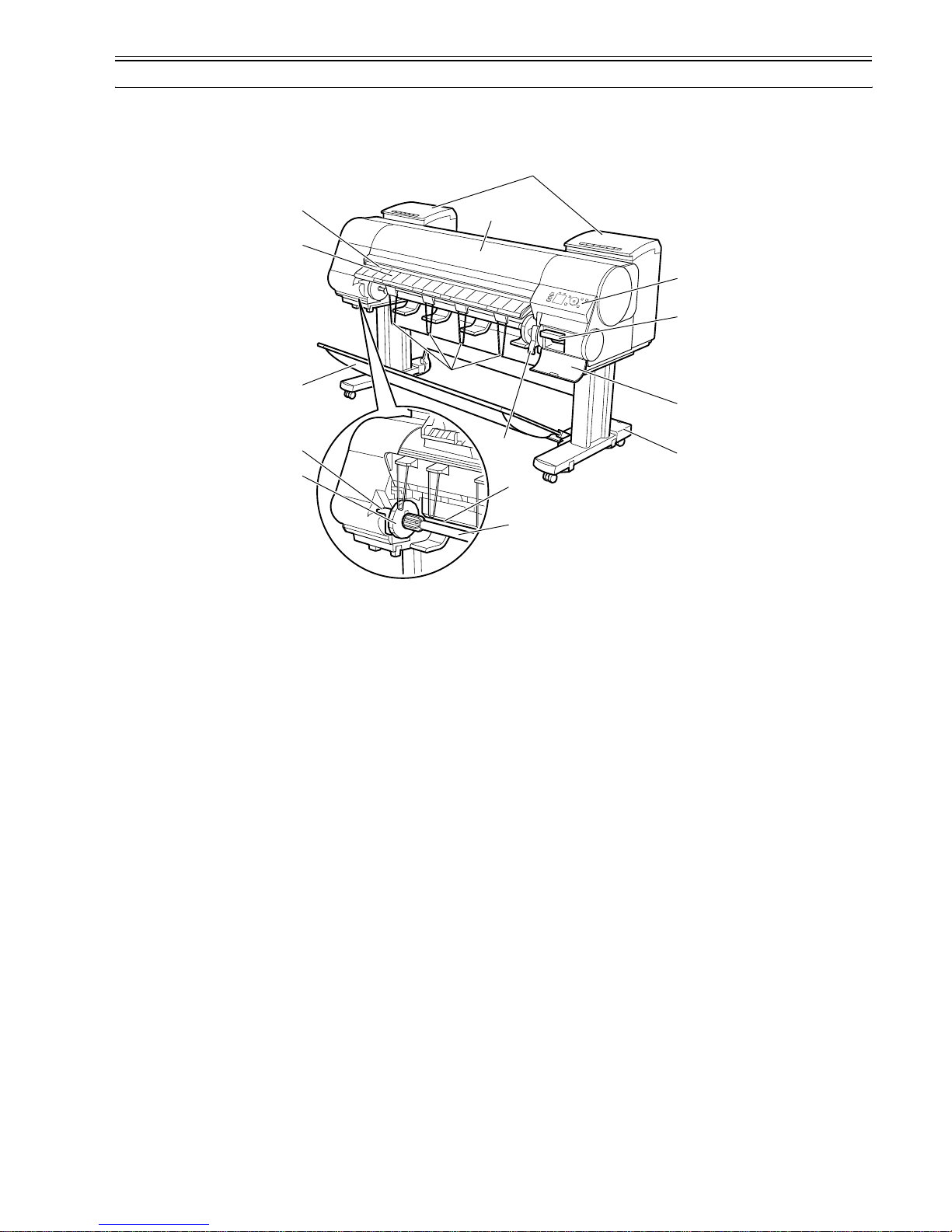
This printer is a large-format printer that prints in a maximum width of 44 inches with high-speed photographic picture quality.
This printer is a stand-mounted type printer and is capable of output to either roll media or cut sheet.
F-1-1
[10]
[3]
[4]
[5]
[6]
[11]
[9]
[12]
[13]
[14]
[15]
[1]
[2]
[8]
[7]
Chapter 1
1-2
F-1-2
T-1-1
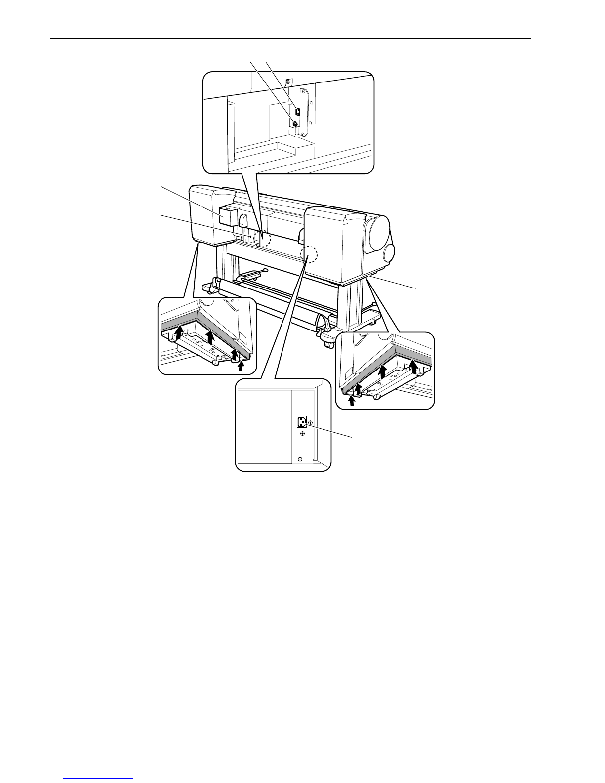
[1] Upper Cover [12] Stand
[2] Ink Tank Cover [13] Maintenance Cartridge Cover
[3] Ejection Slot [14] Maintenance Cartridge
[4] Ejection Guide [15] Operation Panel
[5] Output Stacker [16] Ethernet Port
[6] Roll Holder Slot [17] USB Port
[7] Holder Stopper [18] Accessory Pocket
[8] Roll Holder [19] Media Take-up Unit Power Inlet
[9] Paper Feed Slot [20] Power Supply Connector
[10] Ejection Support [21] Carrying Handles
[11] Release Lever
[17]
[18]
[19]
[20]
[16]
[21]
Chapter 1
1-3
1.2 Features
1.2.1 Features
0024-9414
- Media pass in widths up to 44 inches (1117.6 mm).
- Large ink tanks save the need for their replacement.
- Uninterrupted printing from subtanks.
- BK and MBK inks are loaded concurrently to eliminate the need for their replacement.
- Media take-up unit (option) is supported.
- Media take-up unit (option) can be mounted concurrently with a basket.
- Durability will be added by maintenance kit.
- High resolutions of 2400 x 1200 dpi maximum, coupled with the exceptionally light-fast, water-proof and ozone-proof 12-color pigment inks of MBK, BK, PC,
C, PM, M, Y, R, G, B, GY, and PGY, deliver high-quality photographic picture quality.
- Barcodes printed on roll media make remaining roll media management possible.
- Borderless four-side printing support (roll media) removes laborious cutting work, easing the job of creating posters to a significant degree.
- High-speed printing with a 1-inch head for each color (1,280 nozzles), under bidirectional print control.
- Ink supply through tubing to a completely independent printhead and large-capacity ink tanks.
- The color calibration feature adds to the faithfulness of color reproduction.
- Hard disk drive mounted for greater ease of job management.
Functional enhancements new to this model include:
- A newly developed 12-color pigment ink system "LUCIA E X" is used to improve ru bfastness, chromogenic effect, and bronzing re sistance, ensuring higher-gra de
printing.
- A new mode has been added to improve control of the optimum ink droplet landing order (when in the mode for the highest image quality) and the ink droplet
landing accuracy, ensuring higher-grade printing.
- The network interface (10Base-T/100Base-TX/1000Base-T) compatible with 1000Base-T (Gigabit Ethernet) comes standard with the printer to cope with the
high-speed LAN environment.
1.2.2 Printhead
0013-2742
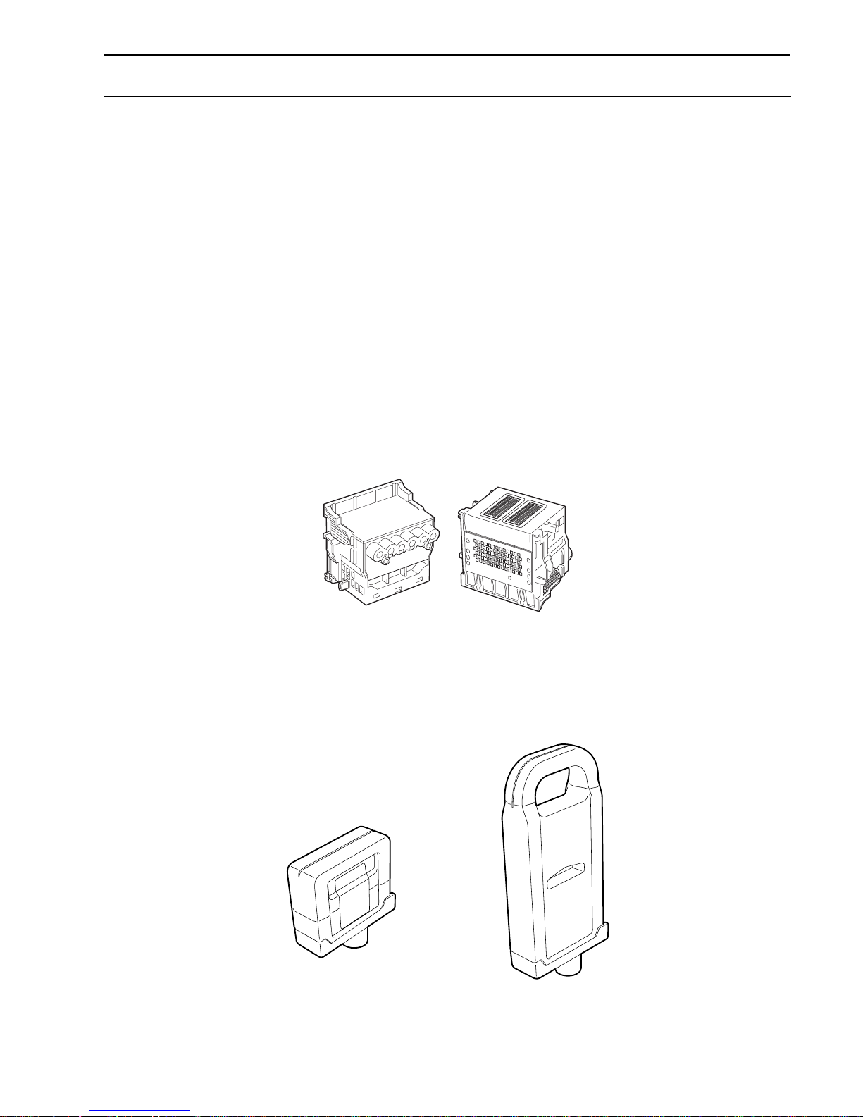
The printhead that mounts on the carriage is an integrated six-color disposable printhead.
It has 2,560 nozzles for each color, comprising two trays of 1,280 nozzles each arranged in a zigzag pattern.
If print quality remains unimproved even after a specified cleaning operation, replace the printhead. Replacement about one year after the date of initial unpacking
is also recommended.
F-1-3
1.2.3 Ink tank
0012-6218
Ink tanks are disposable.
The ink tanks come with 12 colors: mat black (MBK), black (BK), photocyan (PC), cyan (C), photomagenta (PM), magenta (M), yellow (Y), red (R), blue (B),
green (G), gray (GY) and photogray (PGY). Each of these inks are pigment ink.
The tanks are also available in two capacities: 330 mL and 700 mL.
Each tank is furnished with a notch for preventing incorrect installation, which will allow the tank to be installed only at the position marked in the right color.
An ink tank should be replaced when an ink tank replacement prompt message appears or when six months expire after the date of initial unpacking, whichever
occurs earlier.
F-1-4
Chapter 1
1-4
1.2.4 Cutter unit
0013-6369
The cutter unit that mounts on the carriage unit is disposable.
Replace the cutter unit when it gets dull.
F-1-5
1.2.5 Roll holder
0020-5421
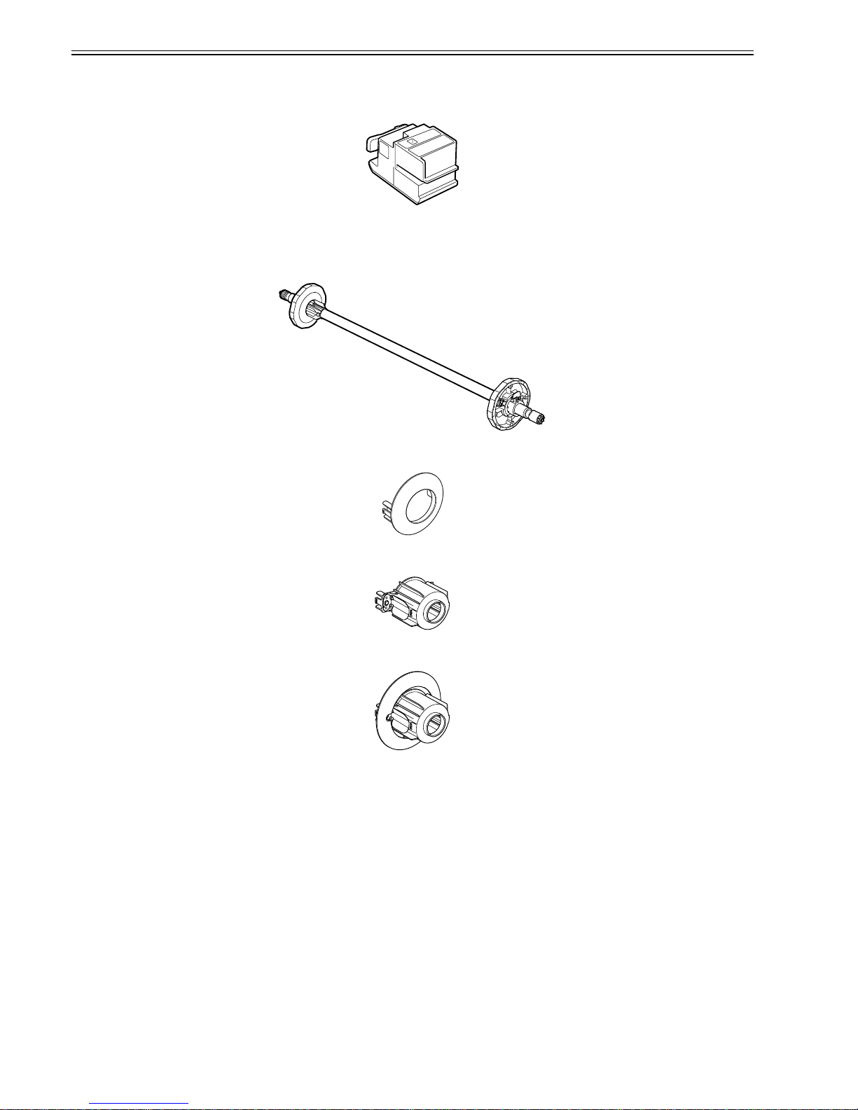
The roller holder accepts paper tubes having inside diameters of both 2 and 3 inches. It is furnished with attachments for 2- and 3-inch diameter paper tubes.
The roll holder clamps the paper tube of a roll not exceeding 150 mm in outside diameter from the inside.
F-1-6
[2-inch paper tube attachment]
F-1-7
[3-inch paper tube attachment 1]
F-1-8
[3-inch paper tube attachment 2]
F-1-9
Chapter 1
1-5
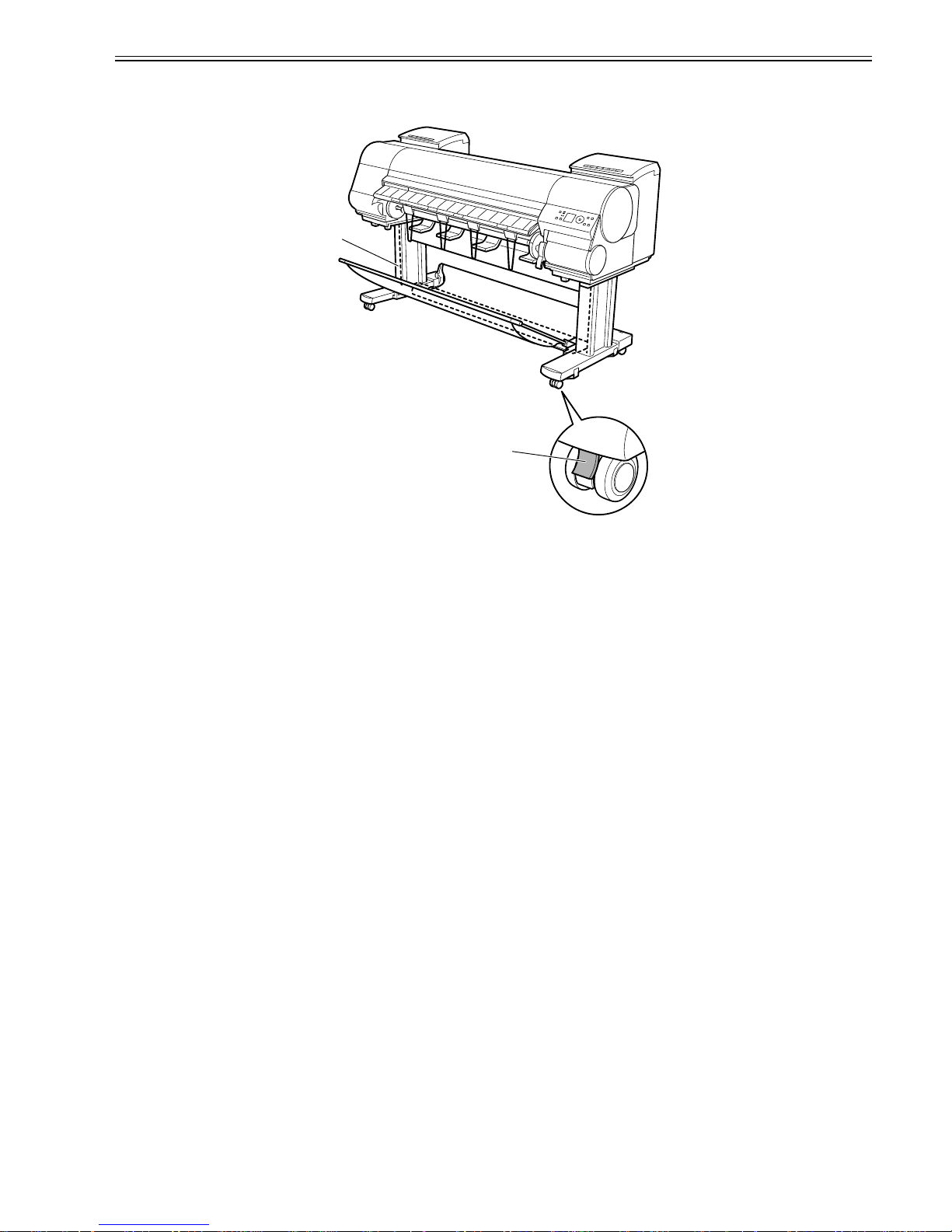
1.2.6 Stand
0017-8299
It is a stand that puts the printer. Equipped with casters so that the printer can be easily moved.
F-1-10
T-1-2
[1] Stand [2] Stopper
O N
[2]
[1]
Chapter 1
1-6
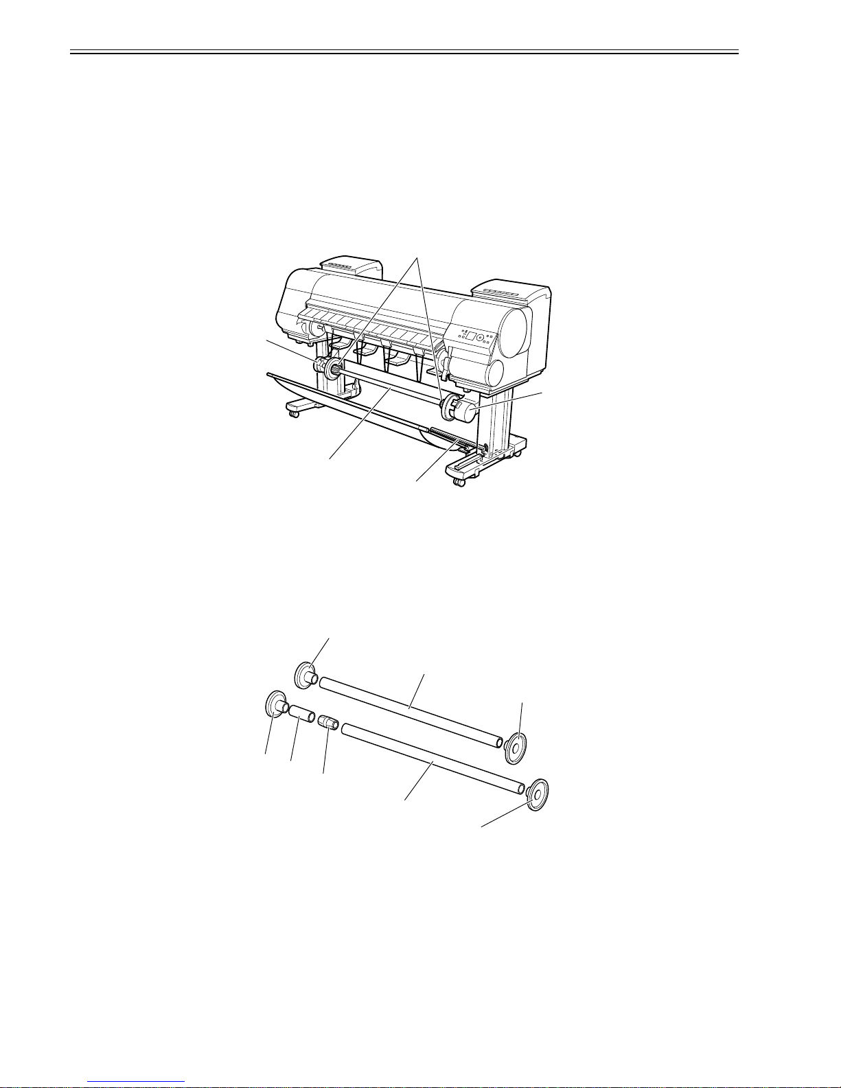
1.2.7 Media take-up unit
0014-8824
Media take-up unit
The media take-up unit takes up roll media, ranging in width from 17 to 44 inches, on a 2 or 3-inch paper tube in roll form after they are printed by the host computer.
Taking up begins automatically when a sensor attached to the bottom of the stand detects a roll delivered after printing falling down due to the weight of a weight
roller.
Rolls may also be manually taken up by using a button on the media take-up unit.
The media take-up unit has an overload protection feature to prevent accidents while taking up rolls. (The feature will shut down the motor automatically when an
overload occurs while taking up a roll.)
Additional features of the media take-up unit include:
- An adapter may be installed to support a 3-inch paper tube.
- Rolls can be rewound by feeding them backward to visually check images.
- Weight rollers varying in length to suit specific roll widths ensure added takeup efficiency.
- The printer detects errors in the media take-up unit by itself.
- Linked with the printer's sleep mode.
F-1-11
T-1-3
Weight
This weight consists of weight roll(7 pcs.)[1], weight flange(2 sets)[2] and weight joint[3].
F-1-12
[1] Left media take-up unit [4] Media take-up unit
[2] Rewind spool [5] 3-inch adapter
[3] Media take-up sensor
[1]
[2]
[3]
[5]
[4]
[2]
[1]
[2]
[2]
[1]
[3]
[1]
[2]
Chapter 1
1-7
1.2.8 Hard disk drive
0017-8472
Each print job received from the host computer is saved to the 80GB hard disk drive(serial ATA connection) attached to the printer, so the printer can print the job
repeatedly as needed, without having to wait for its retransmission from the host computer.
Saving print jobs will offer the following benefits:
- Eased computer workload
A print job may be automatically preserved to the hard disk when printing or may be preserved to the hard disk without printing. A print job preserved can be
printed in as many copies as needed without having to use the host computer.
- Reprinting after error occurrence
If the printer encounters errors, such as paper out, while printing a print job, it can resume the print operation as soon as the errors are cleared, without needing its
retransmission from the host computer.
- Higher print work efficiency
Print jobs can be printed selectively or in a specified number of copies without using a host computer. Multiple print jobs can be printed batched. Unattended print
operations in the nighttime are also possible.
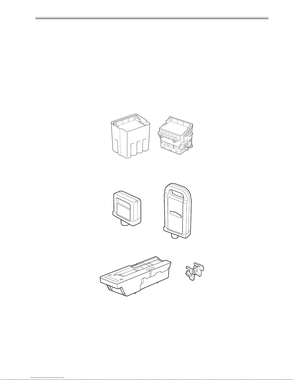
1.2.9 Consumables
0024-9415
Printhead
The expendable printhead is the same as the one that comes with the printer.
F-1-13
Ink tanks
Expendable ink tanks contain 12 colors: mat black, black, photocyan, cyan, photomagenta, magenta, yellow, red, blue, g reen, gray and photogray. Each tank is
available in two capacities: 330 mL and 700 mL.
Usable for six months after unpacking.
F-1-14
Maintenance cartridge
The expendable maintenance cartridge (including the shaft cleaner) is the same as the one that comes with the printer.
F-1-15

Chapter 1
1-8
1.3 Product Specifications
1.3.1 Product Specifications
0024-9416
Type Bubble jet large-sized paper printer (stand model)
Feeding system Roll media: Manual (front loading)
Cut sheet: Paper tray (front loading)
Feeding capacity - Roll media
One roll
Outer diameter of roll: 150 mm or less
- Cut sheet
1 sheet
Delivery method Forward delivery, face up
Sheet delivery capability 1 sheet (using the outout stacker of the stand)
Cutter Automatic cross-cutter (round blade)
Type of media Plain Paper, Plain Paper (High Quality), Plain Paper (High Grade),
Coated Paper, Heavyweight Coated Paper, Premium Matte Paper,
Glossy Photo Paper, Semi-Glossy Photo Paper, Backlit Film, Backprint
Film, Flame-Resistant Cloth, Fine Art Photo, Fine Art Heavyweight
Photo, Fine Art Textured, Canvas Matte, Premium Coated Paper,
Graphic Canvas, Durable Backlit Film, Durable Banner, Matt Coated
Paper, Extra Matt Coated Pape r, Opaque Paper , Hi Res Graphic P aper,
Prem Art Paper Embossed, Prem Art Paper Smooth, Hi Res Barrier
Paper, Scrim Banner, Uni Opaque Backlit Film, Roll-Up Film , Water
Res Art Canvas, Adhesive Matt Vinyl Stretch
Supported thickness 0.07mm to 0.8mm
Media size (Roll media) Width: 254mm (10") to 1118mm (44")
Length: 203mm (8") to 18m (709")
* Outer diameter of roll :150mm or less
* The maximum amount of length may vary by the using operating
system or the applications.
Media size (Cut sheet) Width: 203mm (8") to 1118mm (44")
Length: 203mm (8") to 1600mm (63")
Printable area (Roll media) Internal area, excluding a 5-mm top, bottom and left and right margins.
* The printable area may vary with each type of paper media used.
Printable area (Cut sheet) Internal area, excluding a 5-mm top margin, a 23-mm bottom margin and
5-mm left and right margins.
* The printable area may vary with each type of paper media used.
Printing recommendation area
(Roll media)
Internal area, excluding a 20-mm top margin, a 5-mm bottom margin and
5-mm left and right margins.
Printing recommendation area
(Cut sheet)
Internal area, excluding a 20-mm top margin, a 23-mm bottom margin
and 5-mm left and right margins.
Borderless printing * Roll media only
width: 254mm(10"), 355.6mm(14"), 431.8mm(17"), 515mm(B2/B3),
594mm(A1/A2), 609.6mm(24"), 841mm(A0/A1), 914.4mm(36"),
1030mm(B0/B1), 1066.8mm(42"), 1117.6mm(44")
Memory 384MB
Increase of memory: none
Hard disk drive 80GB (2.5inch, 5400rpm, S-ATA I/F)
Firmware Flash ROM (update from USB or Ethernet)
- Printer description language
GARO (Graphic Arts language with Raster Operation)
Emulation None
Interface USB 2.0 Hi-speed
Network (10BASE-T/100BASE-TX/1000BASE-T)
Operation panel LCD (160 X 128 dots), 13 keys, 5 LEDs
- Panel language
English
- Message language
English, German, French, Italian, Spanish, Chinese, Korean, Russianand
and Japanese
Printhead/Ink Tank type Printhead and separate ink tanks
Printhead PF-05
Structure: Integrated six-color assembly
Number of nozzles: 2,560 for each color
Ink tank PFI-304 BK/MBK/C/M/Y/PC/PM/GY/PGY/R/G/B
PFI-704 BK/MBK/C/M/Y/PC/PM/GY/PGY/R/G/B
Ink type: Pigment ink
Ink tank capacity: PFI-304 330 ml, PFI-704 700 ml
Detection functions (Cover
system)
Cover open/closed detection: Yes
Left and right ink tank cover open/closed detection: Yes
Detection functions (Ink passage
system)
Ink tank presence/absence detection: Yes
Remaining ink level detection: Yes
Maintenance cartridge presence/absence detection: Yes
Used ink tank full detection: Yes

Chapter 1
1-9
1.4 Detailed Specifications
1.4.1 Interface Specifications
0023-2577
a. USB (standard)
(1) Interface type
USB 2.0 Hi-Speed (Full speed (12 Mbits/sec), High speed (480 Mbits/sec))
(2) Data transfer system
Control transfer
Bulk transfer
(3) Signal level
Compliant with the USB standard.
(4) Interface cable
Twisted-pair shielded cable, 5.0 m max.
Compliant with the USB standard.
Wire materials: AWG No.28, data wire pair (AWF: American Wire Gauge)
AWG No.20 to No.28, power distribution wire pair
(5) Interface connector
Printer side: Series B receptacle compliant with USB standard
Cable side: Series B plug compliant with USB standard
b. Network (standard)
(1) Interface type
Interface compliant with IEEE802.3
(2) Data transfer system
IEEE802.0 10Base-T, IEEE802.3u 100Base-TX/Auto-Negotiation, IE EE802.3ab 1000Base-T/Auto-Negotiation, IEEE802.3x Full Duplex
(3) Interface cable
Category 5 (UTP or FTP) cable, 100 m or shorter
Compliant with ANSI/EIA/TIA-568A or ANSI/EIA/TIA-568B
(4) Interface connector
Printer side: Compliant with IEEE802.3, ANSI X3.263, ISO/IEC60603-7
(5) Protocol
IPX/SPX (Netware4.2(J), 5.1(J), 6.0(J)), SNMP, TCP/IP, AppleTalk, HTTP
Detection functions (Carriage
system)
Printhead presence/absence detection: Yes
Carriage position detection: Yes
Carriage home position detection: Yes
Carriage cover open/closed detection: Yes
Carriage temperature detection: Yes
Printhead height detection: Yes
Non-discharging nozzle detection: Yes
Non-discharging nozzle backup feature: Yes
Detection functions (Paper path
system)
Paper presence/absence detection: Yes
Paper width detection: Yes
Skew detection: Yes
Paper release lever position detection: Yes
Remaining roll media detection: Yes
Feed roller rotation detection: Yes
Operating noise Operating: Approx. 50dB (A) or less
Standby: Approx. 35dB (A) or less
Operating environment Temperature: 15 to 35 degrees centigrade
Humidity: 10% to 90%RH
Print quality guaranteed
environment
Temperature: 15 to 30 degrees centigrade
Humidity: 10% to 80%RH
Power supply 100-240 VAC (50/60 Hz)
Power consumption (Maximum) During printing: Max. 190 W
Power consumption In power save (sleep) mode:
100-120 VAC : 5W or less
220-240 VAC : 6W or less
During standby: 1 W or less
Printer unit dimensions
(WxDxH)
1893mm x 975mm x 1144mm (with stand and output stacker)
Weight Approx. 141 kg (with stand and output stacker)
Chapter 1
1-10
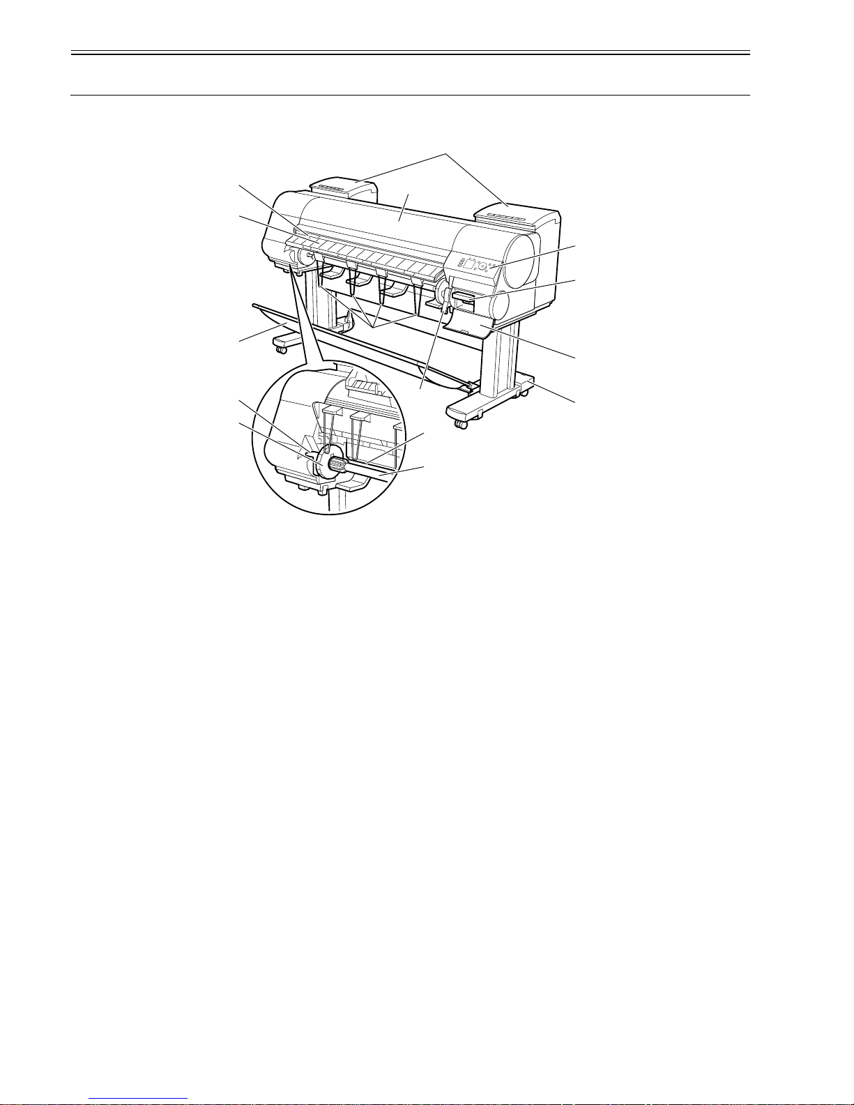
1.5 Names and Functions of Components
1.5.1 Front
0024-9417
F-1-16
[1] Top Cover
Open this cover to install the Printhead, load paper, and remove any jammed paper from inside the printer as needed.
[2] Ink Tank Cover
Open this cover to replace an Ink Tank.
[3] Ejection Slot
All printed matter is ejected from this port.
[4] Ejection Guide
Guides printed documents as they are ejected. Open this guide when loading a roll.
[5] Output Stacker
A cloth tray that catches ejected documents.
[6] Roll Holder Slot
Slide the Roll Holder into this slot.
[7] Holder Stopper
Secure the roll on the Roll Holder with this part.
[8] Roll Holder
Load the roll on this holder.
[9] Paper Feed Slot
When loading a roll, insert the edge of the roll paper here.
[10] Ejection Support
Prevents printed documents from winding around the Roll Holder or Paper Feed Slot.
[11] Release Lever
Releases the Paper Retainer. Lift this lever toward the front of the printer when loading paper.
[12] Stand
A stand that holds the printer. Equipped with casters to facilitate moving the printer.
[13] Maintenance Cartridge Cover
Open this cover to replace the Maintenance Cartridge.
[14] Maintenance Cartridge
Ink used for maintenance purposes such as head cleaning is absorbed. (Replace the cartridge when it is full.)
[15] Operation Panel
Use this panel to operate the printer and check the printer status.
[10]
[3]
[4]
[5]
[6]
[11]
[9]
[12]
[13]
[14]
[15]
[1]
[2]
[8]
[7]
Chapter 1
1-11
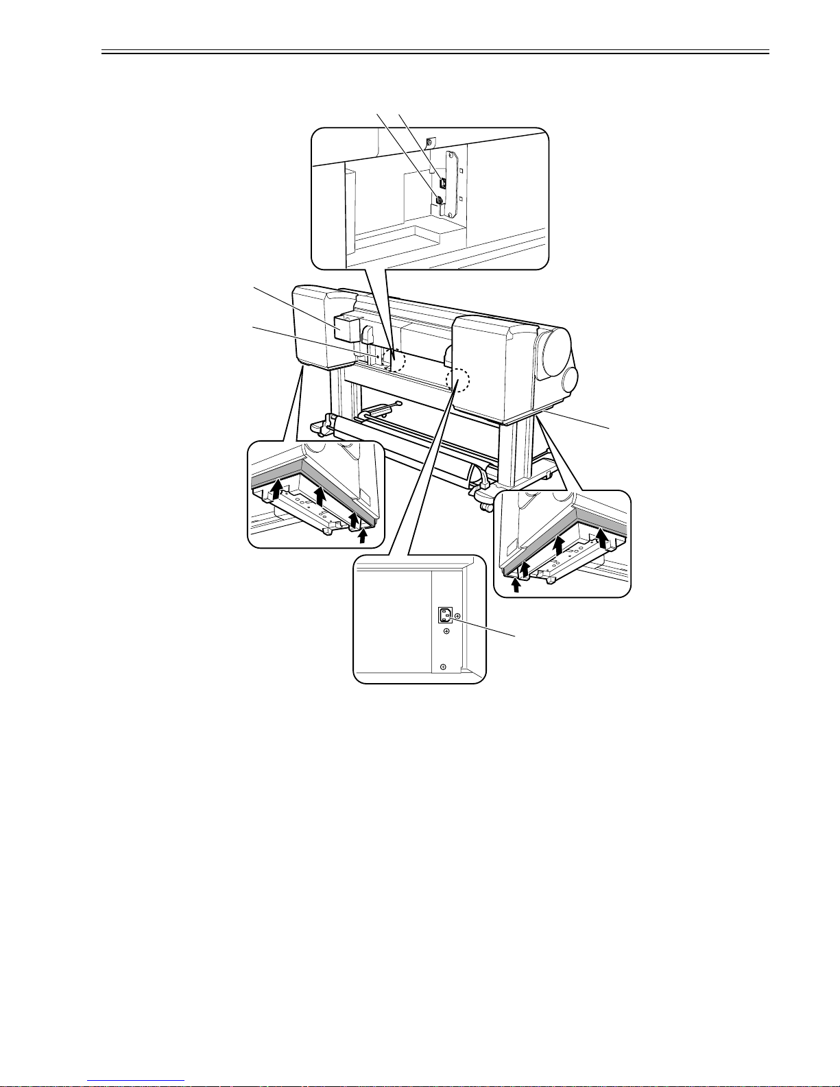
1.5.2 Rear
0024-9418
F-1-17
[1] Ethernet Port
Connect an Ethernet cable to this port. The lamp is lit if the Ethernet cable is connected correctly and communication is possible between the computer and printer.
[2] USB Port
Connect a USB cable to this port. This port is compatible with USB 2.0 Hi-Speed mode.
[3] Accessory Pocket
Holds printer manuals, assembly tools, and other items.
[4] Media Take-up Unit Power Inlet
Connect the power cord of the Media Take-up Unit here.
[5] Power Supply Connector
Connect the power cord to this connector.
[6] Carrying handles
When carrying the printer, have six people hold it by these handles under both sides.
[2]
[3]
[4]
[5]
[1]
[6]
Chapter 1
1-12
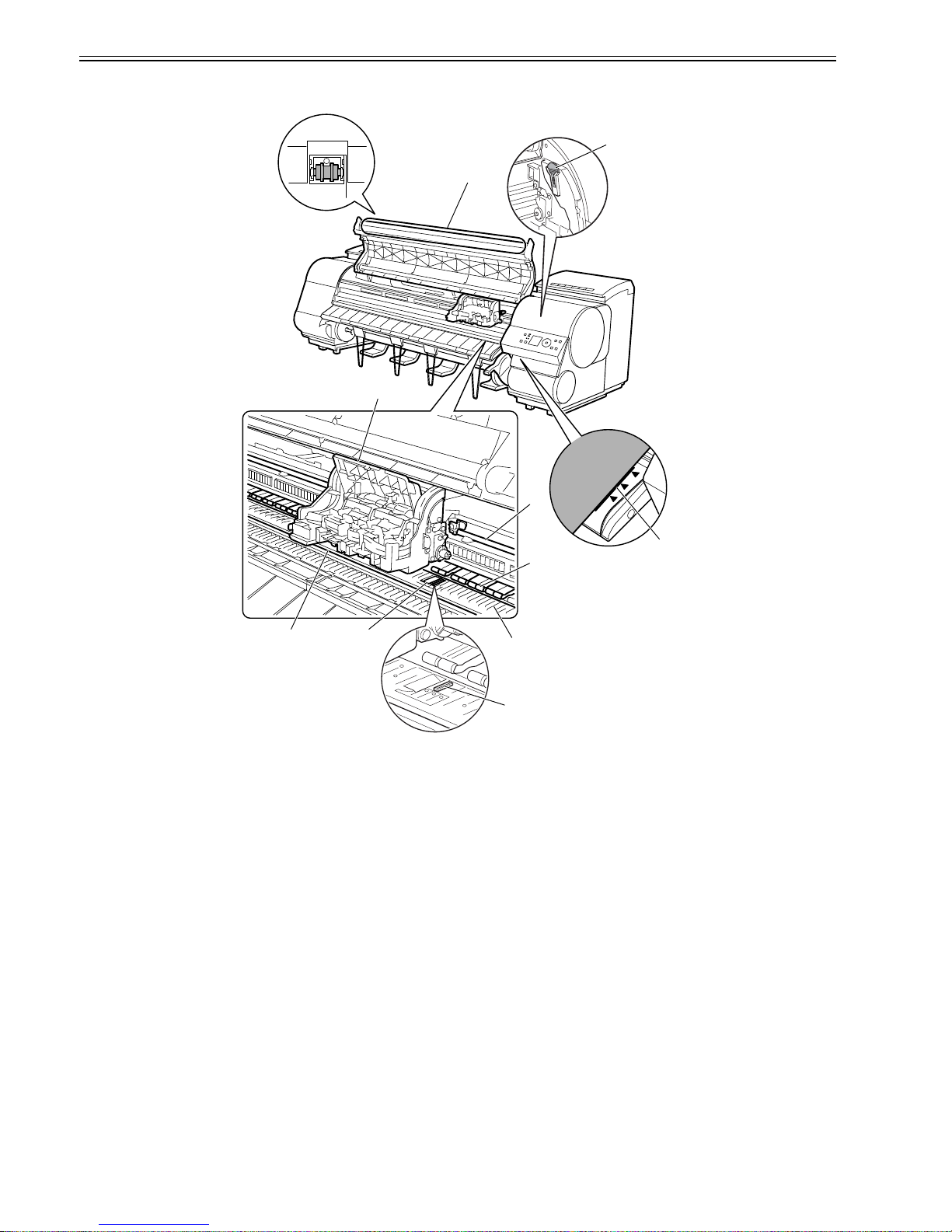
1.5.3 Top Cover (Inside)
0024-9419
F-1-18
[1] Top Cover Roller
Prevents paper from rising when ejected.
[2] Carriage
Moves the Printhead. The carriage serves a key role in printing.
[3] Borderless Printing Ink Grooves
These grooves catch ink outside the edges of paper during borderless printing.
[4] Fixed Blade
The Cutter Unit passes through this blade to cut paper.
[5]Platen
The Printhead moves across the platen to print. The Vacuum holes on the platen hold paper in place.
[6] Pinch Roller
Important in supplying the paper. This retainer holds paper as it is fed.
[7] Carriage Shaft
The Carriage slides along this shaft.
[8] Paper Alignment Line
Align paper with this line when loading it.
[9] Cleaning Brush
When cleaning inside of the Top Cover, use this brush to sweep away paper dust on the Platen.
[10] Switch
Set the switch to the side opposite of the circle mark if the edges of printed images are blurred. Set the switch to the circle mark side before borderless printing.
[1]
[2]
[7]
[8]
[6]
[5]
[4]
[3]
[9]
[10]

Chapter 1
1-13
1.5.4 Carriage
0024-9420
F-1-19
[1] Printhead Fixer Cover
Holds the Printhead in place.
[2] Printhead
Equipped with ink nozzles. Printheads serve a key role in printing.
[3] Carriage Cover
Protects the Carriage.
[4] Cutter Unit
A round-bladed cutter for automatic paper cutting. The cutter blade is retracted inside when not cutting.
[5] Printhead Fixer Lever
Locks the Printhead Fixer Cover.
[6] Shaft Cleaner
Prevents the Carriage Shaft from becoming dirty.
[7] Cutter Unit Detachment Lever
Used when replacing the Cutter Unit.
1.5.5 Ink Tank Cover (Inside)
0017-8301
F-1-20
[1] Ink Tank
Cartridges of ink in each color.
[2] Ink Tank Lock Lever
A lever that locks the Ink Tank in place and protects it. Lift and press down the lever when replacing an Ink Tank. To open it, lift the stopper of the lever until it
stops, and then push it down toward the front. To close it, push it down until it clicks into place.
[3]
[6]
[2]
[4]
[5]
[2]
[1]
[7]
[2]
[1]
[2]
<Left> <Right>
[1]
Chapter 1
1-14
1.6 Basic Operation
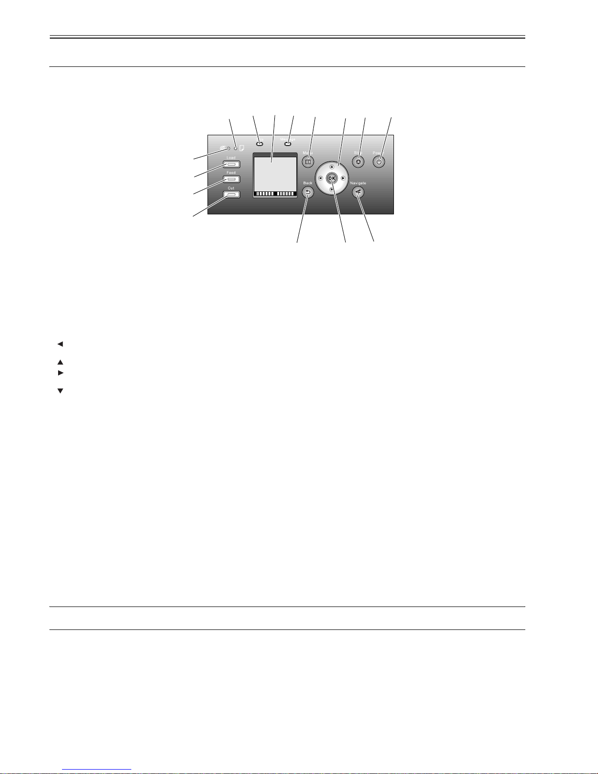
1.6.1 Operation Panel
0024-9421
This section explains the functions of the buttons and the meanings of the LEDs on the operation panel.
F-1-21
[1] Display
Printer menus, statuses, and messages are shown on this display.
[2] [Power] button
Use this button to turn on or off the printer.
When the printer is powered or in the sleep mode, the [Power] button lamp stays lit.
[3] [Stop] button
Use this button to stop execution of a job or drying ink.
[4] [Navi] button
Use this key to confirm the procedures for loading/unloading media, replacing an ink tank, and replacing the printhead.
[5] Direction buttons
- button: Pressing this button on the [tab selection screen] moves the tab. When a menu requiring you to enter a value is selected, pressing this button allows
you to move to the left-hand digit.
- button: Pressing this button in a menu displays the upper item or setting value.
- button: Pressing this button on the [tab selection screen] moves the tab. When a menu requiring you to enter a value is selected, pressing this button allows
you to move to the right-hand digit.
- button: Pressing this button in a menu displays the lower item or setting value.
[6] [OK] button
Pressing this button on the [tab selection screen] displays the menu for the displayed tab.
In the menu for a tab, pressing this button at the item preceded by [+] allows you to move to the bottom layer of menu items, where you can execute a menu item
or set values. Also press this button when a message asking you to press the [OK] button is shown on the display.
[7] [Back] button
Pressing this button displays the preceding screen.
[8] [Menu] button
Pressing this button displays the [tab selection screen] screen.
[9] [Media Cut] button
When roll media is loaded, pressing this button cuts the media.
[10] [Media Feed] button
When roll media is loaded, pressing this button allows you to change the media position.
[11] [Media Change] button
Press this button when loading/replacing media.
[12] [Cut Sheet] lamp (green)
This lamp stays lit when cut sheet is selected as a media type.
[13] [Roll Media] lamp (green)
This lamp stays lit when roll media is selected as a media type.
[14] Message lamp (orange)
- Stays lit: A warning message is being displayed.
- Blinking: An error message is being displayed.
- Not lit: The printer is normal or not powered.
[15] Data reception lamp (green)
- Blinking: When the printer is making prints, this lamp indicates that a print job is being received or processed. When the printer is not making prints, this lamp
indicates that the print job is suspended or the firmware data is being received.
- Not lit: This lamp indicates that there is no print job.
MEMO:
When the printer is in the sleep mode, pressing any button other than the [Power] button wakes up the printer.
[1]
[2]
[3]
[7]
[11]
[4]
[9]
[10]
[15]
[14]
[8]
[5]
[6]
[12]
[13]

Chapter 1
1-15
1.6.2 Display
0023-1271
When the printer starts, the [tab selection screen] appears on the display.
There are four types of tabs on which the relevant printer status, menu, and error information are displayed.
The tab appears as the icon to the top field of display. The tab moves by key or key.
F-1-22
[1] Media tab
This tab shows the printer status and menu related to media. When this tab is shown in reverse video, pressing the [OK] button displays the [Media] menu.
-[A] Top field of display: Shows the media icon in reverse video.
-[B] Middle field of display: Shows the printer status and a menu name.
-[C] Bottom field of display: Shows the media type in the first row and the media size in the second row.
[2] Ink tab
This tab shows the printer status and menu related to ink. When this tab is shown in reverse video, pressing the [OK] button displays the [Ink] menu.
-[A] Top field of display: Shows the ink icon in reverse video.
-[B] Middle field of display: Shows the printer status and a menu name.
-[C] Bottom field of display: Shows the remaining ink levels of the ink tanks loaded in the printer.
[3] Job tab
This tab shows the printer status and menu related to the print job. When this tab is shown in reverse video, pressing the [OK] button displays the [Job] menu.
-[A] Top field of display: Shows the job icon in reverse video.
-[B] Middle field of display: Shows the printer status and a menu name.
[4] Setup/Adjustment tab
This tab shows the printer status and menu related to setup/adjustment. When this tab is shown in reverse video, pressing the [OK] button displays the [Setup/
Adjustment] menu.
-[A] Top field of display: Shows the setup/adjustment icon in reverse video.
-[B] Middle field of display: Shows the printer status and a menu name.
-[C] Bottom field of display: Shows the remaining ink level of the maintenance cartridge.
[1]
[A]
[2] [3] [4]
[B]
[C]

Chapter 1
1-16
1.6.3 Menu
0024-9455
The printer has a Main menu which includes a menu related to maintenance such as adjustment of ink ejection position of each nozzle and head cleaning, a menu
related to printing settings such as auto cutting and ink drying time, and a menu related to parameters such as a message language.
1. Menu Operation
a) Displaying menu on each tab
Press the key or key on the [Tab Selection] screen to select a tab, and press the [OK] key.
A menu associated with each tab is displayed.
Press the key or key to select a menu and press the [OK] key.
The menu is selected and menu items are displayed.
Select a menu with [+] on the left side and press the [OK] key to navigate to lower level menus.
b) Setting menu items
Press the key or key to select an item to set and press the [OK] key.
The item is checked on the left side check box to confirm that it is set.
After 2 seconds, the menu that is one level above is displayed.
c) Setting numeric value for a menu item
Proceed as follows to set a numeric value for an item such as network settings.
1. Press the key or key to move the underscore to the field you want to enter a numeric value.
2. Press the key or key to enter a numeric value.
3. Repeat steps 1 and 2 and press the [OK] key when finished.
 Loading...