

Canon FAX-L380S Series Service Manual

Jan 19 2006
Service Manual
FAX-L380S Series


Application
This manual has been issued by Canon Inc. for qualified persons to learn technical theory, installation, maintenance, and repair
of products. This manual covers all localities where the products are sold. For this reason, there may be information in this
manual that does not apply to your locality.
Corrections
This manual may contain technical inaccuracies or typographical errors due to improvements or changes in products. When
changes occur in applicable products or in the contents of this manual, Canon will release technical information as the need
arises. In the event of major changes in the contents of this manual over a long or short period, Canon will issue a new edition
of this manual.
The following paragraph does not apply to any countries where such provisions are inconsistent with local law.
Trademarks
The product names and company names used in this manual are the registered trademarks of the individual companies.
Copyright
This manual is copyrighted with all rights reserved. Under the copyright laws, this manual may not be copied, reproduced or
translated into another language, in whole or in part, without the written consent of Canon Inc.
COPYRIGHT © 2001 CANON INC.
Printed in Japan
Caution
Use of this manual should be strictly supervised to avoid disclosure of confidential information.
Introduction
Symbols Used
This documentation uses the following symbols to indicate special information:
Symbol Description
Indicates an item of a non-specific nature, possibly classified as Note, Caution, or Warning.
Indicates an item requiring care to avoid electric shocks.
Indicates an item requiring care to avoid combustion (fire).
Indicates an item prohibiting disassembly to avoid electric shocks or problems.
Indicates an item requiring disconnection of the power plug from the electric outlet.
Indicates an item intended to provide notes assisting the understanding of the topic in question.
Indicates an item of reference assisting the understanding of the topic in question.
Provides a description of a service mode.
Provides a description of the nature of an error indication.
Memo
REF.

Introduction
The following rules apply throughout this Service Manual:
1. Each chapter contains sections explaining the purpose of specific functions and the relationship between electrical and mechanical systems with reference to the timing of operation.
In the diagrams, represents the path of mechanical drive; where a signal name accompanies the symbol , the arrow indicates the
direction of the electric signal.
The expression "turn on the power" means flipping on the power switch, closing the front door, and closing the delivery unit door, which results in
supplying the machine with power.
2. In the digital circuits, '1'is used to indicate that the voltage level of a given signal is "High", while '0' is used to indicate "Low".(The voltage value, however, differs from circuit to circuit.) In addition, the asterisk (*) as in "DRMD*" indicates that the DRMD signal goes on when '0'.
In practically all cases, the internal mechanisms of a microprocessor cannot be checked in the field. Therefore, the operations of the microprocessors
used in the machines are not discussed: they are explained in terms of from sensors to the input of the DC controller PCB and from the output of the
DC controller PCB to the loads.
The descriptions in this Service Manual are subject to change without notice for product improvement or other purposes, and major changes will be communicated in the form of Service Information bulletins.
All service persons are expected to have a good understanding of the contents of this Service Manual and all relevant Service Information bulletins and be
able to identify and isolate faults in the machine."


Contents
Contents
Chapter 1 PRODUCT DESCRIPTION
1.1 Product Specifications ................................................................................................................................1- 1
1.1.1 Product Specifications .............................................................................................................................................1- 1
1.1.2 Product Specifications .............................................................................................................................................1- 2
1.2 Detailed Specifications ...............................................................................................................................1- 4
1.2.1 Printing Speed ......................................................................................................................................................... 1- 4
1.2.2 Stack Upon Delivery ................................................................................................................................................1- 4
1.2.3 Scanning Range (Transmission) .............................................................................................................................1- 5
1.2.4 Printing Range (Reception) .....................................................................................................................................1- 5
1.2.5 Printing Range (Printer)...........................................................................................................................................1- 6
1.2.6 System Requirements for Printer Driver ..................................................................................................................1- 7
1.3 Names of Parts ........................................................................................................................................... 1- 7
1.3.1 External View...........................................................................................................................................................1- 7
1.3.2 External View...........................................................................................................................................................1- 8
1.3.3 Operation panel ....................................................................................................................................................... 1- 9
1.4 Safety ....................................................................................................................................................... 1- 10
1.4.1 Safety of Laser Light..............................................................................................................................................1- 10
1.4.2 Handling the Laser Unit .........................................................................................................................................1- 10
1.4.3 Handling the Laser Unit .........................................................................................................................................1- 10
1.4.4 Safety of Toner......................................................................................................................................................1- 11
1.4.5 Backup Battery .....................................................................................................................................................1- 11
Chapter 2 TECHNICAL REFERENCE
2.1 Document Feed and Exposure System ......................................................................................................2- 1
2.1.1 Overview/Configuration ...........................................................................................................................................2- 1
2.1.1.1 Overview .................................................................................................................................................................................. 2- 1
2.2 Laser Exposure ..........................................................................................................................................2- 1
2.2.1 Overview/Configuration ...........................................................................................................................................2- 1
2.2.1.1 Overview .................................................................................................................................................................................. 2- 1
2.3 Image Formation ........................................................................................................................................2- 2
2.3.1 Overview/Configuration ...........................................................................................................................................2- 2
2.3.1.1 Overview .................................................................................................................................................................................. 2- 2
2.4 Pickup and Feed System............................................................................................................................ 2- 3
2.4.1 Overview/Configuration ...........................................................................................................................................2- 3
2.4.1.1 Overview .................................................................................................................................................................................. 2- 3
2.4.1.2 Overview .................................................................................................................................................................................. 2- 4
2.4.2 Detection Jams........................................................................................................................................................2- 4
2.4.2.1 Jam Detection Outline.............................................................................................................................................................. 2- 4
2.4.2.2 Delay Jams .............................................................................................................................................................................. 2- 5
2.4.2.3 Stationary Jams ....................................................................................................................................................................... 2- 5
2.4.2.4 Other Jams .............................................................................................................................................................................. 2- 5
2.5 Fixing Unit...................................................................................................................................................2- 5
2.5.1 Overview/Configuration ...........................................................................................................................................2- 5
2.5.1.1 Overview .................................................................................................................................................................................. 2- 5
2.5.2 Protection Function..................................................................................................................................................2- 6
2.5.2.1 Protective Mechanisms ............................................................................................................................................................ 2- 6
2.5.2.2 Detecting a Fault in the Fixing Assembly ................................................................................................................................. 2- 6
2.6 External and Controls ................................................................................................................................. 2- 7
2.6.1 Power Supply ..........................................................................................................................................................2- 7
2.6.1.1 Backup Battery......................................................................................................................................................................... 2- 7

Contents
2.6.1.2 Energy-Saving Function........................................................................................................................................................... 2- 9
Chapter 3 DISASSEMBLY AND ASSEMBLY
3.1 EXTERNAL AND CONTROLS SYSTEM ................................................................................................... 3- 1
3.1.1 Front Cover..............................................................................................................................................................3- 1
3.1.1.1 Removing the Cassette............................................................................................................................................................ 3- 1
3.1.1.2 Removing the Front Cover ....................................................................................................................................................... 3- 1
3.1.2 Rear Cover...............................................................................................................................................................3- 1
3.1.2.1 Removing the Cassette............................................................................................................................................................ 3- 1
3.1.2.2 Removing the Right Cover ....................................................................................................................................................... 3- 1
3.1.2.3 Removing the Right Cover ....................................................................................................................................................... 3- 1
3.1.2.4 Removing the Left Cover ......................................................................................................................................................... 3- 1
3.1.2.5 Removing the Left Cover ......................................................................................................................................................... 3- 2
3.1.2.6 Removing the Cassette Rear Cover ........................................................................................................................................ 3- 2
3.1.2.7 Removing the Rear Cover ....................................................................................................................................................... 3- 2
3.1.2.8 Removing the Rear Cover ....................................................................................................................................................... 3- 3
3.1.3 Right Cover..............................................................................................................................................................3- 3
3.1.3.1 Removing the Cassette............................................................................................................................................................ 3- 3
3.1.3.2 Removing the Right Cover ....................................................................................................................................................... 3- 3
3.1.3.3 Removing the Right Cover ....................................................................................................................................................... 3- 3
3.1.4 Left Cover ................................................................................................................................................................3- 4
3.1.4.1 Removing the Cassette............................................................................................................................................................ 3- 4
3.1.4.2 Removing the Left Cover ......................................................................................................................................................... 3- 4
3.1.4.3 Removing the Left Cover ......................................................................................................................................................... 3- 4
3.1.5 Operation Panel Unit................................................................................................................................................3- 4
3.1.5.1 Removing the Cassette............................................................................................................................................................ 3- 4
3.1.5.2 Removing the Left Cover ......................................................................................................................................................... 3- 4
3.1.5.3 Removing the Left Cover ......................................................................................................................................................... 3- 5
3.1.5.4 Removing the Operation Unit................................................................................................................................................... 3- 5
3.1.6 SCNT Board.............................................................................................................................................................3- 6
3.1.6.1 Removing the Cassette............................................................................................................................................................ 3- 6
3.1.6.2 Removing the Left Cover ......................................................................................................................................................... 3- 6
3.1.6.3 Removing the Left Cover ......................................................................................................................................................... 3- 6
3.1.6.4 Removing the SCNT Board ..................................................................................................................................................... 3- 6
3.1.7 DCNT Board ............................................................................................................................................................3- 7
3.1.7.1 Removing the Cassette............................................................................................................................................................ 3- 7
3.1.7.2 Removing the Left Cover ......................................................................................................................................................... 3- 7
3.1.7.3 Removing the Left Cover ......................................................................................................................................................... 3- 7
3.1.7.4 Removing the SCNT Unit......................................................................................................................................................... 3- 7
3.1.7.5 Removing the DCNT Board ..................................................................................................................................................... 3- 8
3.1.8 Power Supply PCB ..................................................................................................................................................3- 8
3.1.8.1 Removing the Cassette............................................................................................................................................................ 3- 8
3.1.8.2 Removing the Right Cover ....................................................................................................................................................... 3- 8
3.1.8.3 Removing the Right Cover ....................................................................................................................................................... 3- 8
3.1.8.4 Removing the Left Cover ......................................................................................................................................................... 3- 9
3.1.8.5 Removing the Left Cover ......................................................................................................................................................... 3- 9
3.1.8.6 Removing the Cassette Rear Cover ........................................................................................................................................ 3- 9
3.1.8.7 Removing the Rear Cover ..................................................................................................................................................... 3- 10
3.1.8.8 Removing the Rear Cover ..................................................................................................................................................... 3- 10
3.1.8.9 Removing the SCNT Unit....................................................................................................................................................... 3- 10
3.1.8.10 Removing the Power Supply Shield Plate............................................................................................................................ 3- 10
3.1.8.11 Removing the Power Supply Assembly ............................................................................................................................... 3- 10
3.1.8.12 Removing the Power Supply Board ..................................................................................................................................... 3- 11
3.1.9 High-voitage Power Supply PCB ...........................................................................................................................3- 11
3.1.9.1 Removing the Cassette.......................................................................................................................................................... 3- 11
3.1.9.2 Removing the Right Cover ..................................................................................................................................................... 3- 11
3.1.9.3 Removing the Right Cover ..................................................................................................................................................... 3- 11
3.1.9.4 Removing the Left Cover ....................................................................................................................................................... 3- 12
3.1.9.5 Removing the Left Cover ....................................................................................................................................................... 3- 12
3.1.9.6 Removing the Cassette Rear Cover ...................................................................................................................................... 3- 12

Contents
3.1.9.7 Removing the Rear Cover ..................................................................................................................................................... 3- 13
3.1.9.8 Removing the Rear Cover ..................................................................................................................................................... 3- 13
3.1.9.9 Removing the SCNT Unit....................................................................................................................................................... 3- 13
3.1.9.10 Removing the Power Supply Shield Plate............................................................................................................................ 3- 13
3.1.9.11 Removing the Power Supply Assembly ............................................................................................................................... 3- 13
3.1.9.12 Removing the High-Voltage Power Supply Board ............................................................................................................... 3- 14
3.1.10 Document Sensor Unit.........................................................................................................................................3- 14
3.1.10.1 Removing the Cassette ........................................................................................................................................................ 3- 14
3.1.10.2 Removing the Left Cover ..................................................................................................................................................... 3- 14
3.1.10.3 Removing the Left Cover ..................................................................................................................................................... 3- 14
3.1.10.4 Removing the Operation Unit ............................................................................................................................................... 3- 15
3.1.10.5 Removing the Document Sensor Unit .................................................................................................................................. 3- 15
3.1.11 Top Sensor ..........................................................................................................................................................3- 15
3.1.11.1 Removing the Cassette ........................................................................................................................................................ 3- 15
3.1.11.2 Removing the Right Cover ................................................................................................................................................... 3- 15
3.1.11.3 Removing the Right Cover ................................................................................................................................................... 3- 16
3.1.11.4 Removing the Left Cover ..................................................................................................................................................... 3- 16
3.1.11.5 Removing the Left Cover ..................................................................................................................................................... 3- 16
3.1.11.6 Removing the Cassette Rear Cover .................................................................................................................................... 3- 17
3.1.11.7 Removing the Rear Cover.................................................................................................................................................... 3- 17
3.1.11.8 Removing the Rear Cover.................................................................................................................................................... 3- 17
3.1.11.9 Removing the SCNT Unit ..................................................................................................................................................... 3- 17
3.1.11.10 Removing the Power Supply Shield Plate .......................................................................................................................... 3- 18
3.1.11.11 Removing the Power Supply Assembly ............................................................................................................................. 3- 18
3.1.11.12 Removing the Top Sensor.................................................................................................................................................. 3- 18
3.1.12 Paper Delivery Sensor.........................................................................................................................................3- 18
3.1.12.1 Removing the Cassette ........................................................................................................................................................ 3- 18
3.1.12.2 Removing the Right Cover ................................................................................................................................................... 3- 18
3.1.12.3 Removing the Right Cover ................................................................................................................................................... 3- 19
3.1.12.4 Removing the Left Cover ..................................................................................................................................................... 3- 19
3.1.12.5 Removing the Left Cover ..................................................................................................................................................... 3- 19
3.1.12.6 Removing the Cassette Rear Cover .................................................................................................................................... 3- 20
3.1.12.7 Removing the Rear Cover.................................................................................................................................................... 3- 20
3.1.12.8 Removing the Rear Cover.................................................................................................................................................... 3- 20
3.1.12.9 Removing the SCNT Unit ..................................................................................................................................................... 3- 20
3.1.12.10 Removing the Power Supply Shield Plate .......................................................................................................................... 3- 21
3.1.12.11 Removing the Paper Delivery Sensor ................................................................................................................................ 3- 21
3.1.13 Paper Full Sensor ................................................................................................................................................3- 21
3.1.13.1 Removing the Cassette ........................................................................................................................................................ 3- 21
3.1.13.2 Removing the Right Cover ................................................................................................................................................... 3- 21
3.1.13.3 Removing the Right Cover ................................................................................................................................................... 3- 21
3.1.13.4 Removing the Left Cover ..................................................................................................................................................... 3- 22
3.1.13.5 Removing the Left Cover ..................................................................................................................................................... 3- 22
3.1.13.6 Removing the Cassette Rear Cover .................................................................................................................................... 3- 22
3.1.13.7 Removing the Rear Cover.................................................................................................................................................... 3- 23
3.1.13.8 Removing the Rear Cover.................................................................................................................................................... 3- 23
3.1.13.9 Removing the SCNT Unit ..................................................................................................................................................... 3- 23
3.1.13.10 Removing the Read Unit .................................................................................................................................................... 3- 23
3.1.13.11 Removing the Paper Full Sensor ....................................................................................................................................... 3- 24
3.1.14 Toner Sensor .......................................................................................................................................................3- 24
3.1.14.1 Removing the Cassette ........................................................................................................................................................ 3- 24
3.1.14.2 Removing the Left Cover ..................................................................................................................................................... 3- 24
3.1.14.3 Removing the Left Cover ..................................................................................................................................................... 3- 24
3.1.14.4 Removing the SCNT Unit ..................................................................................................................................................... 3- 25
3.1.14.5 Removing the Toner Sensor ................................................................................................................................................ 3- 25
3.2 Document Feed/Exposure System ...........................................................................................................3- 25
3.2.1 Contact Sensor......................................................................................................................................................3- 25
3.2.1.1 Removing the Cassette.......................................................................................................................................................... 3- 25
3.2.1.2 Removing the Right Cover ..................................................................................................................................................... 3- 25
3.2.1.3 Removing the Right Cover ..................................................................................................................................................... 3- 26
3.2.1.4 Removing the Left Cover ....................................................................................................................................................... 3- 26

Contents
3.2.1.5 Removing the Left Cover ....................................................................................................................................................... 3- 26
3.2.1.6 Removing the SCNT Unit....................................................................................................................................................... 3- 27
3.2.1.7 Removing the Document Guide Unit ..................................................................................................................................... 3- 27
3.2.1.8 Removing the Contact Sensor ............................................................................................................................................... 3- 27
3.2.2 Separation Roller ...................................................................................................................................................3- 28
3.2.2.1 Removing the Cassette.......................................................................................................................................................... 3- 28
3.2.2.2 Removing the Right Cover ..................................................................................................................................................... 3- 28
3.2.2.3 Removing the Right Cover ..................................................................................................................................................... 3- 28
3.2.2.4 Removing the Left Cover ....................................................................................................................................................... 3- 28
3.2.2.5 Removing the Left Cover ....................................................................................................................................................... 3- 29
3.2.2.6 Removing the SCNT Unit....................................................................................................................................................... 3- 29
3.2.2.7 Removing the Document Guide Unit ..................................................................................................................................... 3- 29
3.2.2.8 Removing the Document Feed Motor Unit............................................................................................................................. 3- 30
3.2.2.9 Removing the Document Separation Roller Unit ................................................................................................................... 3- 30
3.2.3 Document Feed Motor ...........................................................................................................................................3- 30
3.2.3.1 Removing the Cassette.......................................................................................................................................................... 3- 30
3.2.3.2 Removing the Left Cover ....................................................................................................................................................... 3- 30
3.2.3.3 Removing the Left Cover ....................................................................................................................................................... 3- 30
3.2.3.4 Removing the Document Feed Motor .................................................................................................................................... 3- 31
3.3 LASER EXPOSURE SYSTEM ................................................................................................................. 3- 31
3.3.1 Laser/Scanner Unit ................................................................................................................................................3- 31
3.3.1.1 Removing the Cassette.......................................................................................................................................................... 3- 31
3.3.1.2 Removing the Right Cover ..................................................................................................................................................... 3- 31
3.3.1.3 Removing the Right Cover ..................................................................................................................................................... 3- 32
3.3.1.4 Removing the Left Cover ....................................................................................................................................................... 3- 32
3.3.1.5 Removing the Left Cover ....................................................................................................................................................... 3- 32
3.3.1.6 Removing the Cassette Rear Cover ...................................................................................................................................... 3- 33
3.3.1.7 Removing the Rear Cover ..................................................................................................................................................... 3- 33
3.3.1.8 Removing the Rear Cover ..................................................................................................................................................... 3- 33
3.3.1.9 Removing the SCNT Unit....................................................................................................................................................... 3- 33
3.3.1.10 Removing the Read Unit ...................................................................................................................................................... 3- 34
3.3.1.11 Removing the Laser/Scanner Unit ....................................................................................................................................... 3- 34
3.4 IMAGE FORMATION SYSTEM................................................................................................................ 3- 34
3.4.1 Transfer Charging Roller........................................................................................................................................3- 34
3.4.1.1 Removing the Transfer Charging Roller ................................................................................................................................ 3- 34
3.5 PICKUP AND FEEDING SYSTEM........................................................................................................... 3- 34
3.5.1 Cassette Pickup Roller...........................................................................................................................................3- 34
3.5.1.1 Removing the Cassette.......................................................................................................................................................... 3- 34
3.5.1.2 Removing the Right Cover ..................................................................................................................................................... 3- 34
3.5.1.3 Removing the Right Cover ..................................................................................................................................................... 3- 35
3.5.1.4 Removing the Gear Unit ........................................................................................................................................................ 3- 35
3.5.1.5 Removing the Tooth-Missing Gear ........................................................................................................................................ 3- 35
3.5.1.6 Removing the Cassette Pickup Roller ................................................................................................................................... 3- 36
3.5.2 Cassette Pickup Solenoid......................................................................................................................................3- 36
3.5.2.1 Removing the Cassette.......................................................................................................................................................... 3- 36
3.5.2.2 Removing the Right Cover ..................................................................................................................................................... 3- 36
3.5.2.3 Removing the Right Cover ..................................................................................................................................................... 3- 36
3.5.2.4 Removing the Left Cover ....................................................................................................................................................... 3- 37
3.5.2.5 Removing the Left Cover ....................................................................................................................................................... 3- 37
3.5.2.6 Removing the Cassette Rear Cover ...................................................................................................................................... 3- 37
3.5.2.7 Removing the Rear Cover ..................................................................................................................................................... 3- 37
3.5.2.8 Removing the Rear Cover ..................................................................................................................................................... 3- 38
3.5.2.9 Removing the SCNT Unit....................................................................................................................................................... 3- 38
3.5.2.10 Removing the Power Supply Shield Plate............................................................................................................................ 3- 38
3.5.2.11 Removing the Power Supply Assembly ............................................................................................................................... 3- 38
3.5.2.12 Removing the Cassette Pickup Solenoid ............................................................................................................................. 3- 39
3.5.3 Cassette Separation Pad.......................................................................................................................................3- 39
3.5.3.1 Removing the Cassette.......................................................................................................................................................... 3- 39
3.5.3.2 Removing the Rear of the Cassette ....................................................................................................................................... 3- 39
3.5.3.3 Removing the Cassette Separation Pad ................................................................................................................................ 3- 39

Contents
3.5.3.4 Removing the Cassette Separation Pad ................................................................................................................................ 3- 39
3.5.4 Paper Feed Roller .................................................................................................................................................3- 40
3.5.4.1 Removing the Cassette.......................................................................................................................................................... 3- 40
3.5.4.2 Removing the Front Cover ..................................................................................................................................................... 3- 40
3.5.4.3 Removing the Right Cover ..................................................................................................................................................... 3- 40
3.5.4.4 Removing the Right Cover ..................................................................................................................................................... 3- 40
3.5.4.5 Removing the Left Cover ....................................................................................................................................................... 3- 41
3.5.4.6 Removing the Left Cover ....................................................................................................................................................... 3- 41
3.5.4.7 Removing the Cassette Rear Cover ...................................................................................................................................... 3- 41
3.5.4.8 Removing the Rear Cover ..................................................................................................................................................... 3- 41
3.5.4.9 Removing the Rear Cover ..................................................................................................................................................... 3- 42
3.5.4.10 Removing the SCNT Unit ..................................................................................................................................................... 3- 42
3.5.4.11 Removing the DCNT Board ................................................................................................................................................. 3- 42
3.5.4.12 Removing the Gear Unit....................................................................................................................................................... 3- 42
3.5.4.13 Removing the Tooth-Missing Gear ...................................................................................................................................... 3- 43
3.5.4.14 Removing the Cartridge Guide............................................................................................................................................. 3- 43
3.5.4.15 Removing the Manual Stay .................................................................................................................................................. 3- 43
3.5.4.16 Removing the Paper Feed Guide......................................................................................................................................... 3- 43
3.5.4.17 Removing the Paper Feed Roller ......................................................................................................................................... 3- 43
3.5.5 Manual Pickup Solenoid ........................................................................................................................................3- 44
3.5.5.1 Removing the Cassette.......................................................................................................................................................... 3- 44
3.5.5.2 Removing the Right Cover ..................................................................................................................................................... 3- 44
3.5.5.3 Removing the Right Cover ..................................................................................................................................................... 3- 44
3.5.5.4 Removing the Left Cover ....................................................................................................................................................... 3- 44
3.5.5.5 Removing the Left Cover ....................................................................................................................................................... 3- 45
3.5.5.6 Removing the Cassette Rear Cover ...................................................................................................................................... 3- 45
3.5.5.7 Removing the Rear Cover ..................................................................................................................................................... 3- 45
3.5.5.8 Removing the Rear Cover ..................................................................................................................................................... 3- 45
3.5.5.9 Removing the SCNT Unit....................................................................................................................................................... 3- 46
3.5.5.10 Removing the Gear Unit....................................................................................................................................................... 3- 46
3.5.5.11 Removing the Tooth-Missing Gear ...................................................................................................................................... 3- 46
3.5.5.12 Removing the Power Supply Shield Plate............................................................................................................................ 3- 46
3.5.5.13 Removing the Power Supply Assembly ............................................................................................................................... 3- 47
3.5.5.14 Removing the Manual Pickup Solenoid ............................................................................................................................... 3- 47
3.5.6 Main Motor.............................................................................................................................................................3- 47
3.5.6.1 Removing the Cassette.......................................................................................................................................................... 3- 47
3.5.6.2 Removing the Right Cover ..................................................................................................................................................... 3- 47
3.5.6.3 Removing the Right Cover ..................................................................................................................................................... 3- 47
3.5.6.4 Removing the Left Cover ....................................................................................................................................................... 3- 48
3.5.6.5 Removing the Left Cover ....................................................................................................................................................... 3- 48
3.5.6.6 Removing the Cassette Rear Cover ...................................................................................................................................... 3- 49
3.5.6.7 Removing the Rear Cover ..................................................................................................................................................... 3- 49
3.5.6.8 Removing the Rear Cover ..................................................................................................................................................... 3- 49
3.5.6.9 Removing the SCNT Unit....................................................................................................................................................... 3- 49
3.5.6.10 Removing the Power Supply Shield Plate............................................................................................................................ 3- 49
3.5.6.11 Removing the Power Supply Assembly ............................................................................................................................... 3- 50
3.5.6.12 Removing the Main Motor .................................................................................................................................................... 3- 50
3.5.7 Gear Unit ...............................................................................................................................................................3- 50
3.5.7.1 Removing the Cassette.......................................................................................................................................................... 3- 50
3.5.7.2 Removing the Right Cover ..................................................................................................................................................... 3- 50
3.5.7.3 Removing the Right Cover ..................................................................................................................................................... 3- 50
3.5.7.4 Removing the Gear Unit ........................................................................................................................................................ 3- 51
3.6 FIXING SYSTEM ...................................................................................................................................... 3- 51
3.6.1 Fixing Film Unit......................................................................................................................................................3- 51
3.6.1.1 Removing the Cassette.......................................................................................................................................................... 3- 51
3.6.1.2 Removing the Right Cover ..................................................................................................................................................... 3- 51
3.6.1.3 Removing the Right Cover ..................................................................................................................................................... 3- 51
3.6.1.4 Removing the Left Cover ....................................................................................................................................................... 3- 52
3.6.1.5 Removing the Left Cover ....................................................................................................................................................... 3- 52
3.6.1.6 Removing the Cassette Rear Cover ...................................................................................................................................... 3- 52
3.6.1.7 Removing the Rear Cover ..................................................................................................................................................... 3- 53

Contents
3.6.1.8 Removing the Rear Cover ..................................................................................................................................................... 3- 53
3.6.1.9 Removing the SCNT Unit....................................................................................................................................................... 3- 53
3.6.1.10 Removing the Read Unit ...................................................................................................................................................... 3- 53
3.6.1.11 Removing the Power Supply Shield Plate............................................................................................................................ 3- 54
3.6.1.12 Removing the Fixing Film Unit ............................................................................................................................................. 3- 54
3.6.2 Fixing Pressure Roller............................................................................................................................................3- 54
3.6.2.1 Removing the Cassette.......................................................................................................................................................... 3- 54
3.6.2.2 Removing the Right Cover ..................................................................................................................................................... 3- 54
3.6.2.3 Removing the Right Cover ..................................................................................................................................................... 3- 55
3.6.2.4 Removing the Left Cover ....................................................................................................................................................... 3- 55
3.6.2.5 Removing the Left Cover ....................................................................................................................................................... 3- 56
3.6.2.6 Removing the Cassette Rear Cover ...................................................................................................................................... 3- 56
3.6.2.7 Removing the Rear Cover ..................................................................................................................................................... 3- 56
3.6.2.8 Removing the Rear Cover ..................................................................................................................................................... 3- 56
3.6.2.9 Removing the SCNT Unit....................................................................................................................................................... 3- 56
3.6.2.10 Removing the Read Unit ...................................................................................................................................................... 3- 57
3.6.2.11 Removing the Power Supply Shield Plate............................................................................................................................ 3- 57
3.6.2.12 Removing the Fixing Film Unit ............................................................................................................................................. 3- 57
3.6.2.13 Removing the Fixing Pressure Roller................................................................................................................................... 3- 58
Chapter 4 MAINTENANCE AND INSPECTION
4.1 Periodically Replaced Parts ....................................................................................................................... 4- 1
4.1.1 Periodic Replacement Parts ....................................................................................................................................4- 1
4.2 Consumables ............................................................................................................................................. 4- 1
4.2.1 Consumable.............................................................................................................................................................4- 1
4.3 Periodical Service....................................................................................................................................... 4- 1
4.3.1 Periodic Service.......................................................................................................................................................4- 1
4.4 Cleaning ..................................................................................................................................................... 4- 1
4.4.1 Items Requiring Cleaning.........................................................................................................................................4- 1
4.4.2 Cleaning Method (external covers)..........................................................................................................................4- 2
4.4.3 Cleaning Method (scanning unit) .............................................................................................................................4- 2
4.4.4 Cleaning Method (printer unit) .................................................................................................................................4- 2
4.4.5 Cleaning Method (printer unit) .................................................................................................................................4- 3
4.5 Lubrications ................................................................................................................................................ 4- 4
4.5.1 Areas Requiring Application of Grease....................................................................................................................4- 4
4.5.2 Delivery Idler Gear...................................................................................................................................................4- 5
4.5.3 Fixing Drive Transmission Gear...............................................................................................................................4- 5
4.5.4 Large Gear Bushing R .............................................................................................................................................4- 6
4.5.5 Large Gear...............................................................................................................................................................4- 6
4.5.6 Feed Gear................................................................................................................................................................4- 6
4.5.7 Internal Gear............................................................................................................................................................4- 7
4.5.8 Large Gear Deceleration Gear/Plate R....................................................................................................................4- 7
4.5.9 Main Motor...............................................................................................................................................................4- 8
4.5.10 Drive Releasing Arm ..............................................................................................................................................4- 8
4.5.11 FU Delivery Roller ..................................................................................................................................................4- 9
4.5.12 Pickup Idler Gear ...................................................................................................................................................4- 9
4.5.13 Feed Deceleration Gear.......................................................................................................................................4- 10
4.5.14 Fixing Deceleration Gear .....................................................................................................................................4- 10
4.5.15 FD Delivery Roller ................................................................................................................................................4- 10
4.5.16 Large Gear Bushing F..........................................................................................................................................4- 11
4.5.17 Pressure Roller ....................................................................................................................................................4- 11
4.5.18 Cassette Pickup Roller.........................................................................................................................................4- 12
4.5.19 Document Feed Roller .........................................................................................................................................4- 12
Chapter 5 TROUBLESHOOTING
5.1 Phenomenon Table .................................................................................................................................... 5- 1

Contents
5.1.1 Symptoms................................................................................................................................................................5- 1
5.2 Measurement and Adjustment.................................................................................................................... 5- 1
5.2.1 Basic Adjustments ................................................................................................................................................... 5- 1
5.2.1.1 Items of Adjustment ................................................................................................................................................................. 5- 1
5.3 Service Tools ..............................................................................................................................................5- 2
5.3.1 Special Tools ...........................................................................................................................................................5- 2
5.4 Error Code ..................................................................................................................................................5- 2
5.4.1 Outline .....................................................................................................................................................................5- 2
5.4.1.1 Error Code Outline ................................................................................................................................................................... 5- 2
5.5 Service Mode..............................................................................................................................................5- 2
5.5.1 Outline .....................................................................................................................................................................5- 2
5.5.1.1 Hardware Switches .................................................................................................................................................................. 5- 2
5.5.1.2 Service Data Setting ................................................................................................................................................................ 5- 2
5.5.1.3 Service Data Entry Method ...................................................................................................................................................... 5- 3
5.5.1.4 Service Data Flowchart ............................................................................................................................................................ 5- 3
5.5.2 Default Settings ....................................................................................................................................................... 5- 9
5.5.2.1 SSSW Default Settings ............................................................................................................................................................ 5- 9
5.5.3 Service Soft Switch Settings (SSSW).................................................................................................................... 5- 17
5.5.3.1 Outline.................................................................................................................................................................................... 5- 17
5.5.3.2 SSSW-SW03 ......................................................................................................................................................................... 5- 17
5.5.3.3 SSSW-SW05 ......................................................................................................................................................................... 5- 18
5.5.3.4 SSSW-SW10 ......................................................................................................................................................................... 5- 18
5.5.3.5 SSSW-SW14 ......................................................................................................................................................................... 5- 19
5.5.3.6 SSSW-SW18 ......................................................................................................................................................................... 5- 19
5.5.3.7 SSSW-SW26 ......................................................................................................................................................................... 5- 20
5.5.3.8 SSSW-SW28 ......................................................................................................................................................................... 5- 20
5.5.4 Menu Switch Settings (MENU) ..............................................................................................................................5- 21
5.5.4.1 #2 MENU ............................................................................................................................................................................... 5- 21
5.5.5 Numeric Parameter Settings (NUMERIC Param.).................................................................................................5- 21
5.5.5.1 #3 NUMERIC Param.............................................................................................................................................................. 5- 21
5.5.6 Counter Indication (COUNTER) ............................................................................................................................5- 22
5.5.6.1 #9 COUNTER ........................................................................................................................................................................ 5- 22
5.5.7 Report Output (REPORT)...................................................................................................................................... 5- 22
5.5.7.1 #10 SERVICE REPORT ........................................................................................................................................................ 5- 22
5.5.7.2 Report Output Automatically .................................................................................................................................................. 5- 28
5.5.8 Data Initialization Mode (CLEAR)..........................................................................................................................5- 28
5.5.8.1 #12 CLEAR ............................................................................................................................................................................ 5- 28
5.5.9 ROM Management (ROM) ....................................................................................................................................5- 28
5.5.9.1 #13 ROM................................................................................................................................................................................ 5- 28
5.5.10 Remote CRG .......................................................................................................................................................5- 28
5.5.10.1 #17 Remote CRG................................................................................................................................................................. 5- 28
5.5.11 Test Mode (TEST) ...............................................................................................................................................5- 30
5.5.11.1 Overview .............................................................................................................................................................................. 5- 30
5.5.11.2 DRAM Test........................................................................................................................................................................... 5- 31
5.5.11.3 Print Test .............................................................................................................................................................................. 5- 32
5.5.11.4 Modem Test ......................................................................................................................................................................... 5- 32
5.5.11.5 Aging Test ............................................................................................................................................................................ 5- 34
5.5.11.6 Faculty Test.......................................................................................................................................................................... 5- 34
Chapter 6 APPENDIX
6.1 Outline of Electrical Components ............................................................................................................... 6- 1
6.1.1 Sensor .....................................................................................................................................................................6- 1
6.1.1.1 Arrangement of Sensors and Switches.................................................................................................................................... 6- 1
6.1.1.2 Arrangement of Sensors and Switches.................................................................................................................................... 6- 1
6.1.2 PCBs .......................................................................................................................................................................6- 2
6.1.2.1 Arrangement of PCBs .............................................................................................................................................................. 6- 2
6.1.2.2 Arrangement of PCBs .............................................................................................................................................................. 6- 3

Contents

Chapter 1 PRODUCT DESCRIPTION


Contents
Contents
1.1 Product Specifications....................................................................................................................................................1-1
1.1.1 Product Specifications ................................................................................................................................................................. 1-1
1.1.2 Product Specifications ................................................................................................................................................................. 1-2
1.2 Detailed Specifications ..................................................................................................................................................1-4
1.2.1 Printing Speed .............................................................................................................................................................................. 1-4
1.2.2 Stack Upon Delivery.................................................................................................................................................................... 1-4
1.2.3 Scanning Range (Transmission) .................................................................................................................................................. 1-5
1.2.4 Printing Range (Reception).......................................................................................................................................................... 1-5
1.2.5 Printing Range (Printer) ............................................................................................................................................................... 1-6
1.2.6 System Requirements for Printer Driver...................................................................................................................................... 1-7
1.3 Names of Parts ...............................................................................................................................................................1-7
1.3.1 External View .............................................................................................................................................................................. 1-7
1.3.2 External View .............................................................................................................................................................................. 1-8
1.3.3 Operation panel ............................................................................................................................................................................ 1-9
1.4 Safety ...........................................................................................................................................................................1-10
1.4.1 Safety of Laser Light ................................................................................................................................................................. 1-10
1.4.2 Handling the Laser Unit ............................................................................................................................................................. 1-10
1.4.3 Handling the Laser Unit ............................................................................................................................................................. 1-10
1.4.4 Safety of Toner .......................................................................................................................................................................... 1-11
1.4.5 Backup Battery.......................................................................................................................................................................... 1-11


Chapter 1
1-1
1.1 Product Specifications
1.1.1 Product Specifications
0011-8335
FAX-L380S
Body installation method Desktop
Exposure Method Semi-conductor laser
Development Method Toner projection
Transfer Method Roller transfer
Fixing method On-demand fixing
Delivery method Facedown /Faceup
Toner level detection function Yes
Toner supply type Toner cartridge replacement /
Cartridge T
Document type Sheet
Maximum document size 216 mm x 1 m (Multiple pages: 216 mm x 356 mm)
Minimum document size 148 mm x 105 mm
ADF capacity Max. 50 sheets (A4, LTR), Max. 20 sheets (LGL)
Effective scanning width 208 mm (A4),
214 mm (LTR/LGL)
Scanning method Contact sensor scanning method
Reproduction ratio 50 to 200 %
Reduction for reception Fixed reduction: Yes,
Auto reduction: 75 to 100 %
Print area Print: 5 mm and more inner from paper egdes/ Copy: 2 mm and more
inner from paper egdes/ Reception output: 2 mm (leading edge), 2 mm
(right/left edge), 6 mm (trailing edge) and more inner from paper egdes
Reading resolution 8 pel/mm (approx. 200 dpi) x 400 dpi (copy scanning: approx. 300 dpi x
300 dpi)
Copying resolution Scanning: approx. 300 dpi x 300 dpi/ Printing: 600 dpi x 600 dpi (1200
dpi equivalent x 600 dpi)
Printing resolution 600 dpi x 600 dpi (1200 dpi equivalent x 600 dpi)
Print speed (A4) approx. 18 sheets/min
Print speed(LTR) approx. 19 sheets/min
Warm-up Time 1 sec. (room tenperature: 20 deg C)
First Print Time approx. 19 sec. (copy)
Cassette paper size A4, B5, A5, Letter, Legal, Executive, Envelope (DL, ISO-C5, COM10,
MONARCH)
Multi-purpose paper size A4, B5, A5, Letter, Legal, Executive, Envelope (DL, ISO-C5, COM10,
MONARCH), User-definable paper (width 76 to 216 mm, length 127 to
356 mm)
Cassette paper type Plain paper, Transparency, Plain paper L, Heavy paper, Heavy paper H
Multi-purpose paper type Plain paper, Transparency, Plain paper L, Heavy paper, Heavy paper H
Cassette capacity Plain paper (64, 75, 80 g/m2): approx. 250 sheets, Heavy paper (90, 105
g/m2): approx. 200 sheets, Heavy paper H (128 g/m2): approx. 100
sheets, Transparency: approx. 100 sheets, Label: approx. 100 sheets,
Envelope: approx. 20 sheets
Multi-purpose capacity 1 sheet
Continuous reproduction 99 sheets
Energy save mode Yes
Operating environment
(Temperature range)
10 to 32.5 deg C
Operating environment
(Humidity range)
20 to 80 %RH
Power supply rating AC200-240 V, 50-60 Hz
Power consumption (Maximum) approx. 530 W
Dimensions 438 mm x 401 mm x 336 mm (main body)
Weight approx. 11 kg
Option TELEPHONE 6 KIT
Applicable lines Analog line (one line), -PSTN (public Switched Telephone Network)
Handset CT-19 (Option)
Transmission method Half-duplex
Transmission control protocol ITU-T V.8 protocol/ V.34 protocol, ITU-T T.30 binary protocol
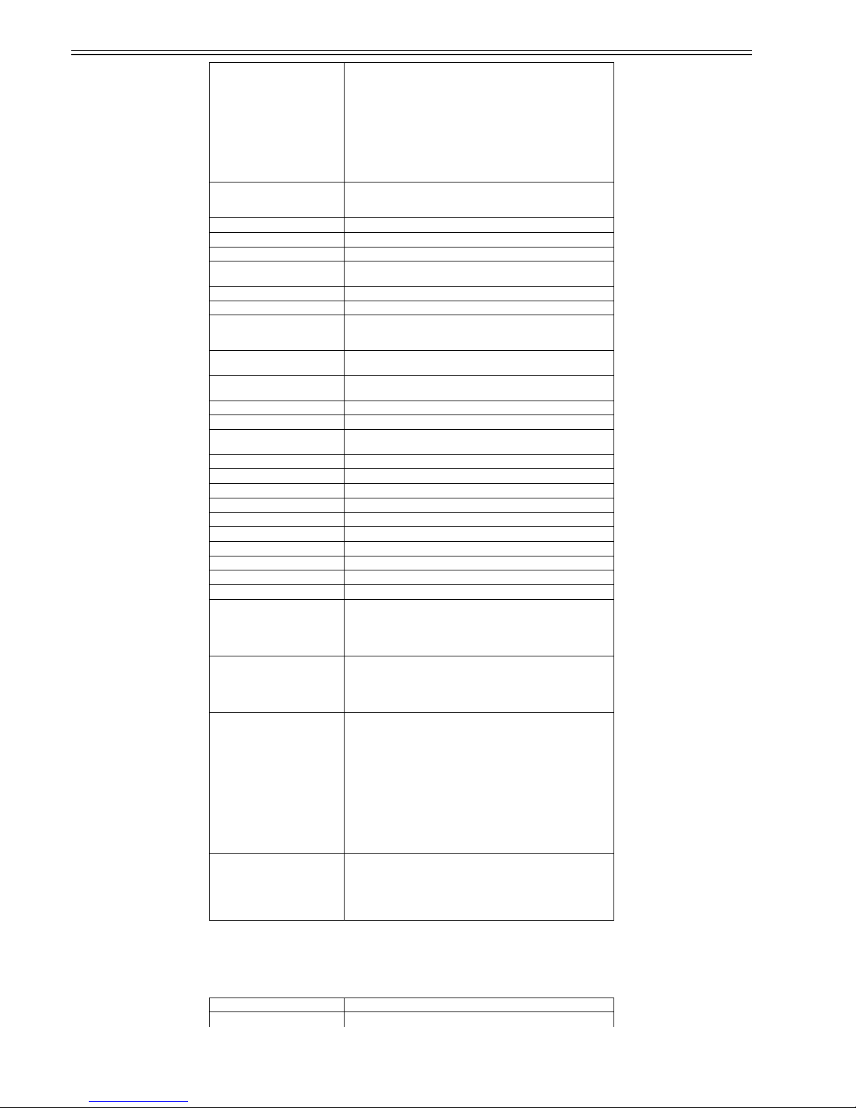
Chapter 1
1-2
1.1.2 Product Specifications
0011-8362
FAX-L390
Modulation method G3 image signals:
ITU-T V.27ter (4.8k, 2.4k bps),
ITU-T V.29 (9.6k, 7.2k bps),
ITU-T V.17 (14.4k, 12.0k, TC9.6k, TC7.2k bps),
ITU-T V.34 (33.6k, 31.2k, 28.8k, 26.4k, 24.0k, 21.6k, 19.2k, 16.8k,
14.4k, 12.0k, 9.6k, 7.2k, 4.8k, 2.4k bps) /
G3 procedure signals:
ITU-T V.21 (No.2) 300 bps,
ITU-T V.8 300 bps,
ITU-T V.34 1200 bps, 600 bps
Transmission speed 33.6k, 31.2k, 28.8k, 26.4k, 24k, 21.6k, 19.2k, 16.8k, 14.4k, 12k, TC9.6k,
TC7.2k, 9.6k, 7.2k, 4.8k, 2.4k bps,
With automatic fallback fuction
Coding method JBIG, MMR, MR, MH
Error correction method ITU-T ECM
Transmission output level approx. -11 dBm
Reception input level V.34: -11 to -43 dBm /
V.17, V.27ter, V.29: -6 to -43 dBm
Modem CONEXANT FM336Plus
Half tone 256-gradation error diffusion system
Dialing Manual dial: Numeric buttons,
Auto dial (One-touch: 32, Coded dial: 100),
Group dial: max.131
Broadcast transmission Max. 142 destinations (One-touch: 32, Coded dial: 100, Numeric
buttons: 10)
Delayed transmission Max. 142 destinations (One-touch: 32, Coded dial: 100, Numeric
buttons: 10), Transmission reservation: Max. 20
Subaddress transmission None
Confidential transmission None
Relay broadcast originating
transmission
None
Relay broadcast transmission None
Polling transmission Yes
Dual access Maximum reservations: 20
FAX/TEL switching Yes / Method: CNG detection, Message: None, Pseudo CI: Yes
Answering machine connection Yes / Method: Telephone answering priority type
Remote reception Yes / Method: ID call# (tone)
Confidential reception None
Polling reception Yes
Memory reception approx. 510 sheets (Canon FAX standard chart No.1)
Closed network communication None
System data backup Backup contents: dial registration data, user data, service data, activity
management reoprt /
Backup IC: 128 Kbyte SRAM /
Backup battery: Lithium battery /
Battery life: approx. 5 years
Image data backup Backup contents: memory reception, memory transmission, broadcast
transmission, delayed transmission, polling transmission image data /
Backup IC: 16 Mbyte DRAM /
Backup battery: Rechargeable capacitor /
Backup time: approx. 1 hour
Activity management Activity management report (every 20 communications),
One-touch dial list,
Coded dial list,
Group dial list,
User data list,
Transmission report,
Reception report,
Multi Tx/Rx report,
Memory clear report,
Document memory list /
Service report:
Sysytem data list,
Sysytem dump list
Others Summer time function: Yes,
Directory function: Yes,
Forced memory reception: None,
2 on 1: None,
LCD display: 2 rows x 20 digits,
Stamp: None
Body installation method Desktop
Exposure Method Semi-conductor laser

Chapter 1
1-3
Development Method Toner projection
Transfer Method Roller transfer
Fixing method On-demand fixing
Delivery method Facedown /Faceup
Toner level detection function Yes
Toner supply type Toner cartridge replacement /
Cartridge T
Document type Sheet
Maximum document size 216 mm x 1 m (Multiple pages: 216 mm x 356 mm)
Minimum document size 148 mm x 105 mm
ADF capacity Max. 50 sheets (A4, LTR), Max. 20 sheets (LGL)
Effective scanning width 208 mm (A4),
214 mm (LTR/LGL)
Scanning method Contact sensor scanning method
Reproduction ratio 50 to 200 %
Reduction for reception Fixed reduction: Yes,
Auto reduction: 75 to 100 %
Print area Print: 5 mm and more inner from paper egdes/ Copy: 2 mm and more
inner from paper egdes/ Reception output: 2 mm (leading edge), 2 mm
(right/left edge), 6 mm (trailing edge) and more inner from paper egdes
Reading resolution 8 pel/mm (approx. 200 dpi) x 400 dpi (copy scanning: approx. 300 dpi x
300 dpi)
Copying resolution Scanning: approx. 300 dpi x 300 dpi/ Printing: 600 dpi x 600 dpi (1200
dpi equivalent x 600 dpi)
Printing resolution 600 dpi x 600 dpi (1200 dpi equivalent x 600 dpi)
Print speed (A4) approx. 18 sheets/min
Print speed(LTR) approx. 19 sheets/min
Warm-up Time 1 sec. (room tenperature: 20 deg C)
First Print Time approx. 19 sec. (copy)
Cassette paper size A4, Letter, Legal
Multi-purpose paper size A4, B5, A5, Letter, Legal, Executive, Envelope (DL, ISO-C5, COM10,
MONARCH), User-definable paper (width 76 to 216 mm, length 127 to
356 mm)
Cassette paper type Plain paper
Multi-purpose paper type Plain paper, Transparency, Plain paper L, Heavy paper, Heavy paper H
Cassette capacity Plain paper (64, 75, 80 g/m2): approx. 500 sheets
Multi-purpose capacity 1 sheet
Continuous reproduction 99 sheets
Energy save mode Yes
Operating environment
(Temperature range)
10 to 32.5 deg C
Operating environment
(Humidity range)
20 to 80 %RH
Power supply rating AC200-240 V, 50-60 Hz
Power consumption (Maximum) approx. 530 W
Dimensions 441 mm x 466 mm x 392 mm (main body)
Weight approx. 12.1 kg
Option TELEPHONE 6 KIT
Applicable lines Analog line (one line), -PSTN (public Switched Telephone Network)
Handset CT-19 (Option)
Transmission method Half-duplex
Transmission control protocol ITU-T V.8 protocol/ V.34 protocol, ITU-T T.30 binary protocol
Modulation method G3 image signals:
ITU-T V.27ter (4.8k, 2.4k bps),
ITU-T V.29 (9.6k, 7.2k bps),
ITU-T V.17 (14.4k, 12.0k, TC9.6k, TC7.2k bps),
ITU-T V.34 (33.6k, 31.2k, 28.8k, 26.4k, 24.0k, 21.6k, 19.2k, 16.8k,
14.4k, 12.0k, 9.6k, 7.2k, 4.8k, 2.4k bps) /
G3 procedure signals:
ITU-T V.21 (No.2) 300 bps,
ITU-T V.8 300 bps,
ITU-T V.34 1200 bps, 600 bps
Transmission speed 33.6k, 31.2k, 28.8k, 26.4k, 24k, 21.6k, 19.2k, 16.8k, 14.4k, 12k, TC9.6k,
TC7.2k, 9.6k, 7.2k, 4.8k, 2.4k bps,
With automatic fallback fuction
Coding method JBIG, MMR, MR, MH
Error correction method ITU-T ECM
Transmission output level approx. -11 dBm
Reception input level V.34: -11 to -43 dBm /
V.17, V.27ter, V.29: -6 to -43 dBm
Modem CONEXANT FM336Plus
Half tone 256-gradation error diffusion system
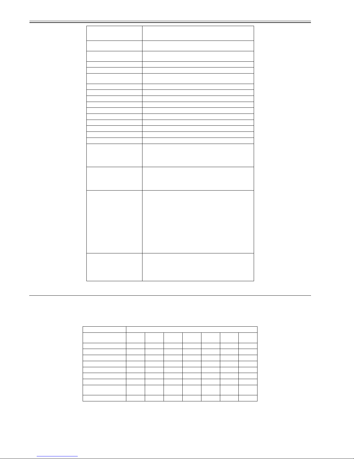
Chapter 1
1-4
1.2 Detailed Specifications
1.2.1 Printing Speed
0011-4667
/ / FAX-L390 / / / FAX-L380S
T-1-1
(unit: sheets/min)
1.2.2 Stack Upon Delivery
0011-4668
/ / FAX-L390 / / / FAX-L380S
Dialing Manual dial: Numeric buttons,
Auto dial (One-touch: 32, Coded dial: 100),
Group dial: max.131
Broadcast transmission Max. 142 destinations (One-touch: 32, Coded dial: 100, Numeric
buttons: 10)
Delayed transmission Max. 142 destinations (One-touch: 32, Coded dial: 100, Numeric
buttons: 10), Transmission reservation: Max. 20
Subaddress transmission None
Confidential transmission None
Relay broadcast originating
transmission
None
Relay broadcast transmission None
Polling transmission Yes
Dual access Maximum reservations: 20
FAX/TEL switching Yes / Method: CNG detection, Message: None, Pseudo CI: Yes
Answering machine connection Yes / Method: Telephone answering priority type
Remote reception Yes / Method: ID call# (tone)
Confidential reception None
Polling reception Yes
Memory reception approx. 510 sheets (Canon FAX standard chart No.1)
Closed network communication None
System data backup Backup contents: dial registration data, user data, service data, activity
management reoprt /
Backup IC: 128 Kbyte SRAM /
Backup battery: Lithium battery /
Battery life: approx. 5 years
Image data backup Backup contents: memory reception, memory transmission, broadcast
transmission, delayed transmission, polling transmission image data /
Backup IC: 16 Mbyte DRAM /
Backup battery: Rechargeable capacitor /
Backup time: approx. 1 hour
Activity management User report:
Activity management report (every 20 communications),
One-touch dial list,
Coded dial list,
Group dial list,
User data list,
Transmission report,
Reception report,
Multi Tx/Rx report,
Memory clear report,
Document memory list /
Service report:
Sysytem data list,
Sysytem dump list
Others Summer time function: Yes,
Directory function: Yes,
Forced memory reception: None,
2 on 1: None,
LCD display: 2 rows x 20 digits,
Stamp: None
Fixing mode
Paper size Plain
paper
Plain
paper L
Heavy
paper
Heavy
paper H
Transpar
ency
Envelope COM10
A4 (64 to 90 g/m2) 18 18 18 12 18 - -
B5 (64 to 90 g/m2) 88448 --
A5 (64 to 90 g/m2) 88448- -
A4 (105 to 128 g/m2) - - 18 12 - - -
B5 (105 to 128 g/m2) - - 4 4 - - -
LTR (75 to 90 g/m2) 1919191219 - -
LGL (75 to 90 g/m2)15------
LTR (Bond 75 to 90 g/m2,
105 g/m2)
--1912---
Envelope -----44
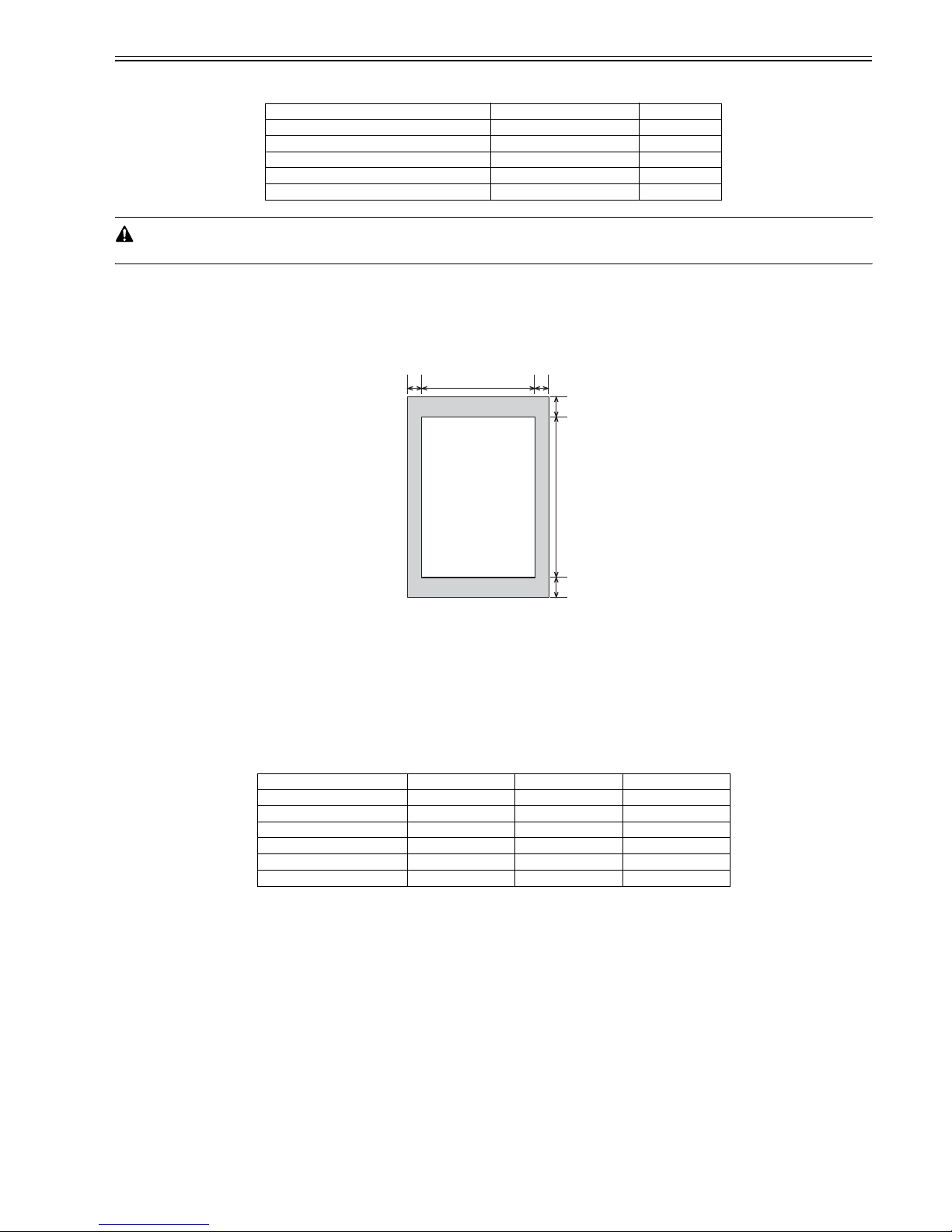
Chapter 1
1-5
T-1-2
The values herein are estimates only and are subject to change for product improvement.
1.2.3 Scanning Range (Transmission)
0011-8371
/ FAX-L390 / FAX-L380S
F-1-1
T-1-3
T-1-4
1.2.4 Printing Range (Reception)
0011-4670
/ / FAX-L390 / / / FAX-L380S
Paper type Face-down Face-up
Plain paper (64 to 90 g/m2) Approx. 50 sheets 1 sheet
Heavy paper (91 to 128 g/m2) Approx. 30 sheets 1 sheet
Transparency Approx. 10 sheets 1 sheet
Label Approx. 10 sheets 1 sheet
Envelope Approx. 10 sheets 1 sheet
[1] Document leading edge [6] Effective scanning length
[2] Left margin [7] Bottom margin
[3] Effective scanning width [8] Scanning drop out range
[4] Right margin [9] Scanning range
[5] Top margin [10] Document trailing edge
Item A4 Letter Legal
Effective scanning width 208 +1.0/-1.0 mm 214 +1.0/-1.0 mm 214 +1.0/-1.0 mm
Effective scanning length (Book) 293 +4.0/-4.0 mm 275 +4.0/-4.0 mm 352 +4.0/-4.0 mm
Left margin 1.0 +2.0/-2.0 mm 1.0 +2.0/-2.0 mm 1.0 +2.0/-2.0 mm
Right margin 1.0 mm 1.0 mm 1.0 mm
Top margin 2.0 +2.0/-2.0 mm 2.0 +2.0/-2.0 mm 2.0 +2.0/-2.0 mm
Bottom margin 2.0 +2.0/-2.0 mm 2.0 +2.0/-2.0 mm 2.0 +2.0/-2.0 mm
[9]
[8]
[4][2]
[5]
[7]
[3]
[6]
[1]
[10]
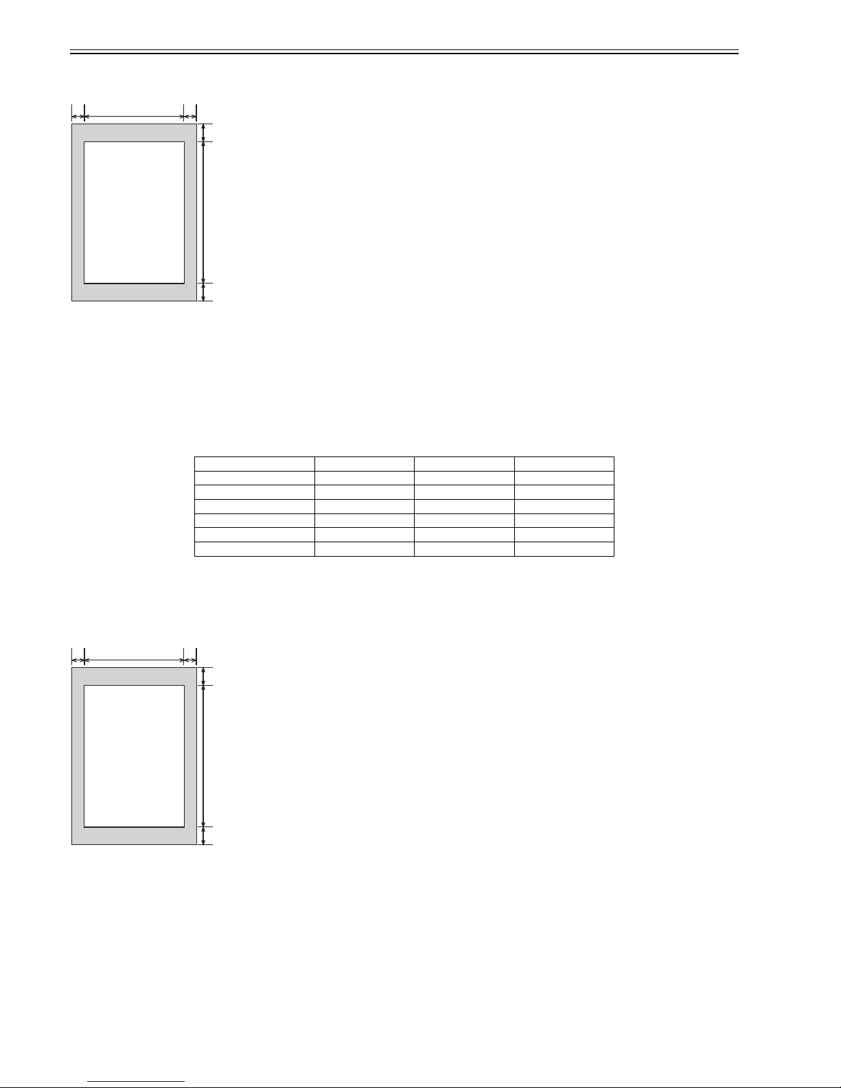
Chapter 1
1-6
F-1-2
T-1-5
T-1-6
1.2.5 Printing Range (Printer)
0011-4671
/ / FAX-L390 / / / FAX-L380S
F-1-3
T-1-7
[1] Paper leading edge [6] Effective printing length
[2] Left margin [7] Bottom margin
[3] Effective printing width [8] Printing drop out range
[4] Right margin [9] Printing range
[5] Top margin [10] Paper trailing edge
Item A4 Letter Legal
Effective printing width 206 +2.0/-2.0 mm 212 +2.0/-2.0 mm 212 +2.0/-2.0 mm
Effective printing length 289 +3.0/-3.0 mm 271.4 +3.0/-3.0 mm 347.6 +3.0/-3.0 mm
Left margin 2.0 +2.0/-2.0 mm 2.0 +2.0/-2.0 mm 2.0 +2.0/-2.0 mm
Right margin 2.0 +3.0/-2.0 mm 2.0 +3.0/-2.0 mm 2.0 +3.0/-2.0 mm
Top margin 4.0 +2.0/-2.0 mm 4.0 +2.0/-2.0 mm 4.0 +2.0/-2.0 mm
Bottom margin 6.0 +7.0/-4.0 mm 6.0 +7.0/-4.0 mm 6.0 +7.0/-4.0 mm
[1] Paper leading edge [6] Effective printing length
[2] Left margin [7] Bottom margin
[3] Effective printing width [8] Printing drop out range
[4] Right margin [9] Printing range
[5] Top margin [10] Paper trailing edge
[9]
[8]
[4][2]
[5]
[7]
[3]
[6]
[1]
[10]
[9]
[8]
[4][2]
[5]
[7]
[3]
[6]
[1]
[10]

Chapter 1
1-7
T-1-8
1.2.6 System Requirements for Printer Driver
0011-4672
/ / FAX-L390 / / / FAX-L380S
Printer Driver
CARPS (Canon Advanced Raster Printing System) printer driver.
Operating System
Windows 98, Windows Me, Windows 2000, or Windows XP (x86 architecture).
Computer
Any computer on whitch Windows 98, Windows Me, Windows 2000, or Windows XP runs properly.
Hardware Environment
Using the CARPS software requires following computer environment.
-IBM or IBM-compatible PC
-CD-ROM drive or network environment with the access to CD-ROM
-PC equipped with a USB port and the USB class driver installed
T-1-9
*Logon as a user account with Adoministrator' rights is recommended.
1.3 Names of Parts
1.3.1 External View
0011-4673
FAX-L380S
<Front View>
F-1-4
T-1-10
Item A4 Letter Legal
Effective printing width 200 mm 206 mm 206 mm
Effective printing length 287 mm 269 mm 346 mm
Left margin 5.0 mm 5.0 mm 5.0 mm
Right margin 5.0 mm 5.0 mm 5.0 mm
Top margin 5.0 mm 5.0 mm 5.0 mm
Bottom margin 5.0 mm 5.0 mm 5.0 mm
OS CPU RAM Available Free Disk Space
Windows 98 Intel Pentium 90 MHz or greater
32 MB or
greater
100 MB or greater
Windows Me Intel Pentium 150 MHz or greater
32 MB or
greater
100 MB or greater
Windows 2000*
Professional
Intel Pentium 133 MHz or greater, or
compatible micro processors (up to 2
processors are supported)
64 MB or
greater
500 MB or greater
Windows XP* Pentium Family 233 MHz or greater
64 MB or
greater
500 MB or greater
[1] Document feeder tray [6] Output tray
[2] ADF (Automatic Document Feeder) [7] Front (Printer) cover
[3] Document output tray [8] Multi-purpose feeder
[4] Slide guides [9] Cassette
[1] [2]
[3]
[4]
[5]
[6]
[7]
[8]
[9]
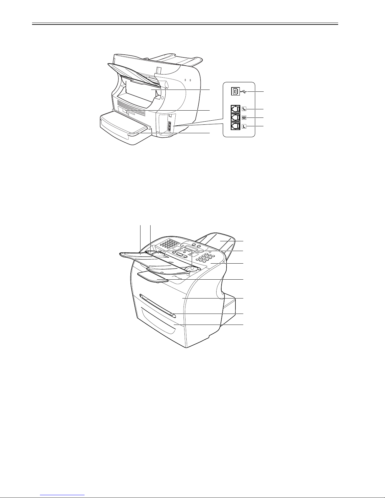
Chapter 1
1-8
<Rear View>
F-1-5
T-1-11
1.3.2 External View
0011-5590
FAX-L390
<Front View>
F-1-6
T-1-12
<Rear View>
[5] Operation panel
[1] USB port [5] Face up cover
[2] Handset jack [6] Power socket
[3] Extension phone jack [7] Extension cover
[4] Telephone line jack
[1] Document feeder tray [6] Output tray
[2] ADF (Automatic Document Feeder) [7] Front (Printer) cover
[3] Document output tray [8] Multi-purpose feeder
[4] Slide guides [9] Cassette
[5] Operation panel
[1]
[2]
[5]
[6]
[7]
[3]
[4]
[1] [2]
[3
]
[4
]
[5
]
[6
]
[7
]
[8
]
[9
]
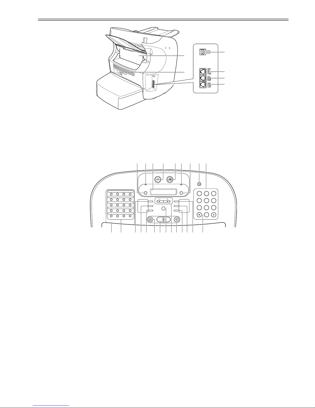
Chapter 1
1-9
F-1-7
T-1-13
1.3.3 Operation panel
0011-8385
/ FAX-L390 / / / FAX-L380S
F-1-8
T-1-14
One-Touch Speed Dial Panel Open
[1] USB port [4] Telephone line jack
[2] Handset jack [5] Face up cover
[3] Extension phone jack [6] Power socket
[1] Menu button [13] Image Quality button
[2] In use/Memory indicator [14] Stop/Reset button
[3] LCD display [15] Cursor buttons
[4] COPY button [16] OK button
[5] FAX button [17] Start button
[6] Alarm indicator [18] Hook button
[7] System Monitor button [19] Directory button
[8] Energy Saver button [20] Coded Dial button
[9] Numeric buttons [21] Redial/Pause button
[10] Tone button [22] One-Touch Speed Dial buttons
[11] Enlarge/Reduce button [23] One-Touch Speed Dial panel
[12] Exposure button
[1
]
[2
]
[3
]
[4
]
[5]
[6]
3
01
02
03
04
080706
05
11 1210
09
161514
13
18 2019
17
12
456
78
0
9
[1] [2] [3] [4] [5] [6] [7] [8] [9]
[23] [22] [21][20][19] [18][17][16][15][14][13][12][11] [10]
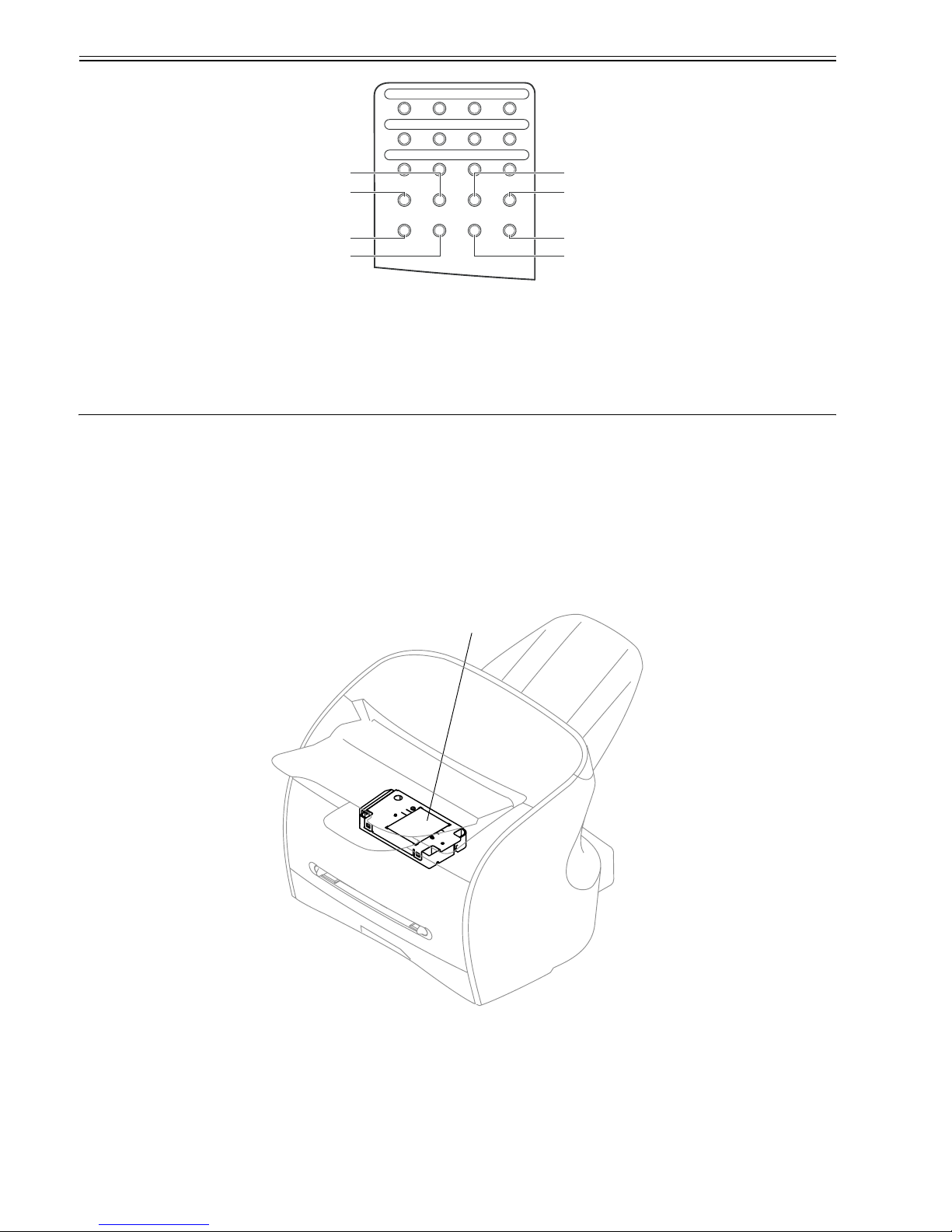
Chapter 1
1-10
F-1-9
T-1-15
1.4 Safety
1.4.1 Safety of Laser Light
0011-4675
/ / FAX-L390 / / / FAX-L380S
Laser radiation could be hazardous to the human body. For this reason, laser radiation emitted inside this machine is hermetically sealed within the protective housing and external cover. No radiation can leaak from the machine in the normal operation of the product by the user.
1.4.2 Handling the Laser Unit
0011-4676
/ / FAX-L380S
The laser scanner unit emits invisible laser light inside it. If exposed to laser light, the human eye can irreparably be damaged. Never attempt to disassemble the
laser scanner unit. (It is not designed for servicing in the field).
The covers around the laser scanner unit are identified by the following label [1].
F-1-10
1.4.3 Handling the Laser Unit
0011-6390
/ / FAX-L390
The laser scanner unit emits invisible laser light inside it. If exposed to laser light, the human eye can irreparably be damaged. Never attempt to disassemble the
laser scanner unit. (It is not designed for servicing in the field).
The covers around the laser scanner unit are identified by the following label [1].
[1] Report button [5] Delayed Transmission button
[2] Receive Mode button [6] Polling button
[3] R button [7] Clear button
[4] Space button [8] Delete button
21
22
23
24
282726
25
31 3230
29
[1]
[2]
[3]
[4]
[8]
[7]
[6]
[5]
[1]
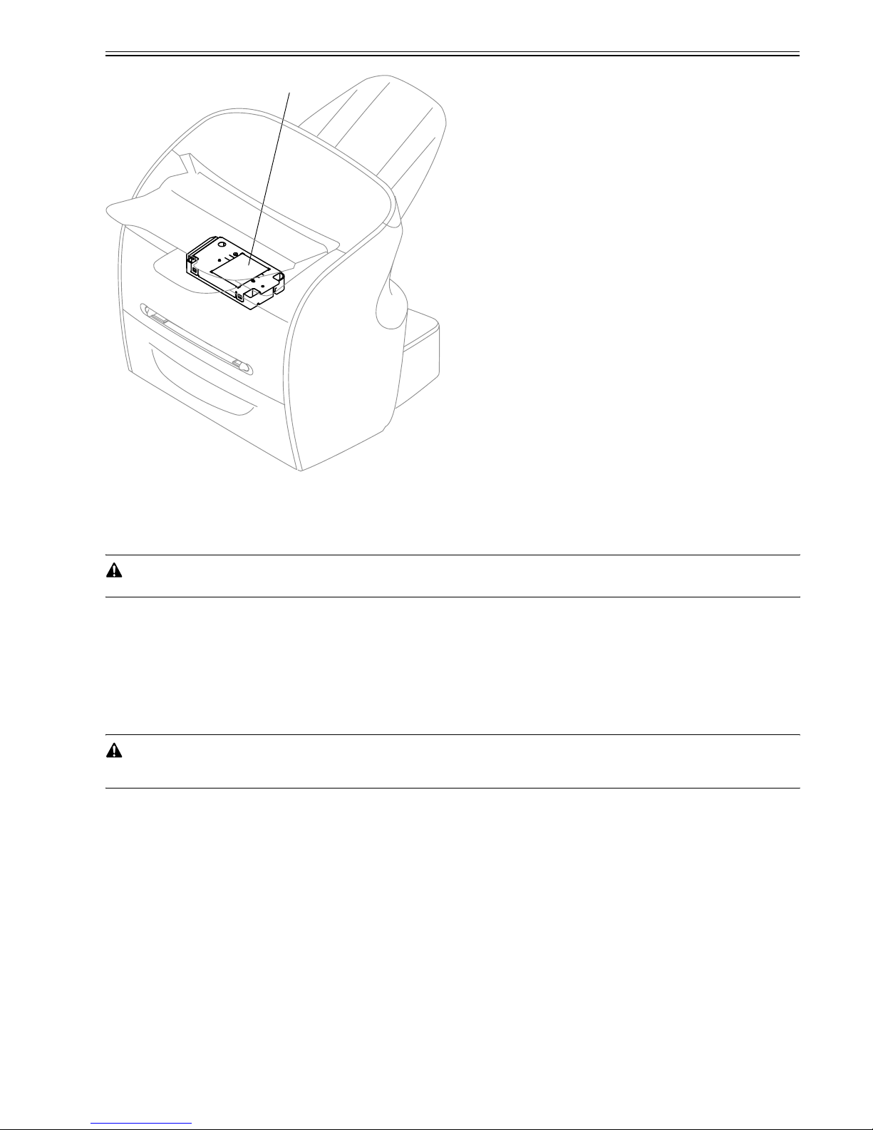
Chapter 1
1-11
F-1-11
1.4.4 Safety of Toner
0011-4677
/ / FAX-L390 / / / FAX-L380S
The machine's toner is a non-toxic material composed of plastic, iron, and small amounts of dye.
Do not put the toner into fire. It may explode.
Toner on the Skin or Clothes
1. If your skin or clothes came into contact with toner, wash with water at once.
2. Do not use warm or hot water, which will cause the toner to jell, permanently fusing it with the fibers of the clothes.
3. Do not bring toner into contact with vinyl material. They are likely to react with each other.
1.4.5 Backup Battery
0012-5205
/ / FAX-L390 / / / FAX-L380S
The machine's SCNT PCB are equipped with a lithium battery (1 pc. each) serving as a backup source of power in the event of a power shortage or when the power
plug is removed.
Risk of explosion if battery is replaced by an incorrect type.
Dispose of used batteries according to the instructions.
[1]

 Loading...