

Canon FAX-L360 Series, AX-L360 Service Reference Manual

HY8-90CZ-000
JULY 2002
COPYRIGHT
2002 CANON INC. CANON FAX-L360 JULY 2002 PRINTED IN JAPAN (IMPRIME AU JAPON)
REVISION 0
SERVICE REFERENCE
MANUAL
FAX-L360 H12-2493 230V EC
FAX-L360 H12-2494 230V UK
FAX-L360 H12-2495 230V GER
FAX-L360 H12-2497 230V FRN
TELEPHONE 6 KIT H12-3773 230V HUN/POL
TELEPHONE 6 KIT H12-3774 230V CZE
TELEPHONE 6 KIT H12-3775 230V SLO
TELEPHONE 6 KIT H12-3776 230V S.A.
TELEPHONE 6 KIT H12-3813 230V GER/FRN
TELEPHONE 6 KIT H12-3823 230V EU
TELEPHONE 6 KIT H12-3824 230V UK
(EC/UK/GER/FRN)

1
I. PREFACE
This manual is based on the following manuals, and only includes dif ferences between FAX-L350 and
FAX-L360.
HY8-10AM-000 FAX-L350 SERVICE MANUAL, Rev.0
HY8-30AJ-000 FAX-L350 PARTS CATALOG, Rev.0
HY8-80AL-000 FAX-L350 CIRCUIT DIAGRAM, Rev.0
II. CONTENTS
CHAPTER 1 : POINTS OF DIFFERENCE FROM THE ORIGINAL MACHINE
This chapter explains the differences between this machine and the original one.
CHAPTER 2 : CIRCUIT DIAGRAM
This chapter contain the pages which are different from those in the Circuit Diagram
for FAX-L350.

2
CHAPTER 1
POINTS OF DIFFERNECE
FROM THE ORIGINALMACHINE

3
1. Parts change
For details of any change in parts numbers, see the Par ts Catalog.
2. Specification change
Canges have been made to the electrical circuitry, and the functions of the NCU board have
been integrated with those of the SCNT board. In this Service Reference Manual, detailed
explanations of the electrical circuitry have been omitted (to respect the decision not to disclose
detailed information in technical documentation, e.g., on ICs).
Body color Cool White
Power consumption standby less than 4W / less than 500W (when operating)
Modulation method
G3 image signals ITU-T V.27ter, V.29, V .17, V.34
G3 procedure signals ITU-T V.21
Modem IC FM336plus
JBIG None
T ransmission/Reception FAX-L360: Approx. 400 pages
memory
Copy resolution Scanning 400 dpi x 300 dpi (direct copy)
200 dpi x 300 dpi (memory copy)
Interface specifications
interface USB only
Support software Windows 98/Me/2000/XP
Windows 95/NT 4.0 (Not support)
Other Summer time added.
Detecting a Residual Cartr idge added.

4
Interface Spcifications
Serial interface (USB)
a) Specifications
Interface Type
USB Interface (Universal Serial Bus; USB Specification Release Number 1.10)
Data T ransmission
Control transfer method
Bulk transfer method
Signal V oltage Level
Input:
Input defference sensitivity: +0.2V (Max.)
Common-mode defference: +0.8V to +2.5V
Output:
Static output high: +2.8V to 3.6V
Static outpu low: less than +0.3V
Input/Output
Data signal pulled up with 3.3V
VBUS signal pulled up with 5.5V
Interface Cable
Twisted-pair shielded cable
USB standard compatible required
Material AWG No. 28, Data pair (AWG: American Wire Gauge)
AWG No. 20 to No. 28, Power distribution pair
Interface Connector
Printer-side USB standard, Series B receptacle
Cable-side USB standard, Series B plug
USB Connector (JUSB1)
JUSB1 PC Signal name Description
1 ← 1 VBUS Cable power supply (+5V DC)
2 — 2 D– Data
3 — 3 D+Data
4 — 4 GND Cable GND
2
1
3
4
5
b) USB interface
USB is a serial interface which connects up to 127 peripheral devices to a host computer, and transmits data at a highspeed rate of 12Mbps. Hot plugging, in which connecting/disconnecting devices while the host or the printer is in use, is
supported. Each device is connected to a hub's port, where each port’s detection/disconnection status is returned to the
host.
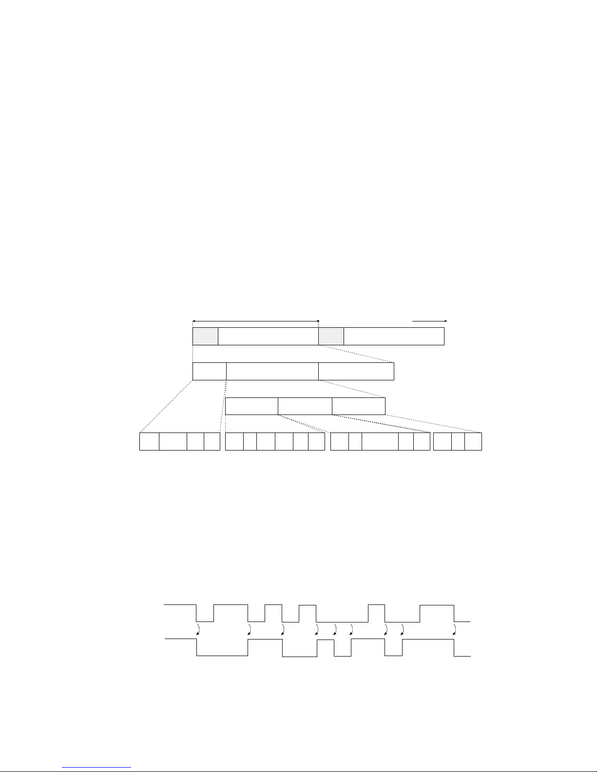
Data transfer
The data transfer in USB is executed in terms of the transfer unit called a frame, a time frame of approximately 1ms, into
which the data is divided. Data is transferred by piling up these frames.
All packets begin with a SYNC (synchronizing) field to synchronize with the local clock, and are separated with an
EOP (End of Packet) field.
Frame lines begin with an SOF (Start of Frame) packet. An SOF is composed of a PID (Packet Identification Field) that
represents the type of the packet and the direction, frame number, and a CRC (Cyclic Redundancy Check) used for
error-check.
Inside a frame is a packet line containing a token packet, data packet and a handshak e pac ket, whic h indicates the status
of the flow control.
A token packet is composed of a PID, an address field which can specify up to 128 addresses, an ENDP (endpoint) f ield,
and a CRC.
Inside a data packet are a PID, data field, CRC, and EOP.
Only a PID is present inside the handshake packet.
USB Data Transfer
Encoding/Decoding the Data
In USB, data transfer lines are ultimately encoded with NRZI (Non Return to Zero Invert) method. When the original
data bit is 0, sent data bits are inverted; when the original data bit is 1, the value is retained.
Howev er, if the level of the transferred data remain unchanged f or a certain period of time , the recei ving side may not be
able to synchronize with the data sample position, which will result in data bits being out of phase. This is prevented by
a method called bit stuffing; when data bit 1 is repeated 6 times, one 0 bit is added to the original data before encoded
with NRZI.
NRZI
SOF
1Frame (approx. 1ms)
SOF Printer Other Function
SYNC
Frame
Number
CRC SYNC
Token Data Handshake
PID ADDR ENDP CRCEOP EOP SYNC PID DATA CRC EOP SYNC PID EOP
SOF
Frame Line
Frame Structure
Packet Line
Packet Structure
Time Lapse
Idle
Idle
NRZI
0110101000100110
Data

6
Supported Software
The following table shows the relationship between available drivers and the interfaces for this model.
FAX-L290 Suite
USB I/F
Windows 95 not
supported
Windows 98 conditionally
supported*
Windows NT 4.0 not
supported
Windows 2000 conditionally
supported*
Windows Me conditionally
supported*
Windows XP conditionally
supported*
*: A USB connection applies to Windows XP/Me/2000 pre-install models and to
pre-install models upgraded to Windows XP/Me/2000 from Windows 98 or later.
Windows Drivers
Win98.Me LBP Printer Driver (USB suppor ted)
Win2000.XP LBP Printer Driver (USB supported)

7
3. Setting the Language and Country
When you connect the power cord to an AC outlet for the first time, you need to select the
language for the LCD display. For some countries, you also need to select the country where
you are using the FAX machine. The FAX machine automatically switches the selectable
settings and the default settings in the menus to suit the selected country.
Follow this procedure to set the language and country.
After connecting the power cord, the display changes from PLEASE WAIT to DISPLAY LANGUAGE.
Once you have selected the language and country, these setting menus will not appear next
time you connect the power cord.
Normally, the country selection window will appear when the user has selected a language.
A shift to the screen, howe ver, will not occur if the user has selected any of the following for #5
TYPE in service mode:
EUROPE2, POLAND, ASIA, SLOVENIA, SINGAPORE, CHINA, SAF, HONG KONG, N.Z,
AUSTRALIA, UK, GERMAN, ITALY, SWEDEN.

8
4. Setting the Summer Time
Some countries adopt the summer time system that shifts the clock time ahead or back according to the change in seasons. You can select if the time information in your FAX changes
to match your country summer time system and set the day and time when the summer time
begins and ends.
Operation at the Start of Summer Time
When the time selected for BEGIN DATE/TIME comes, the time stored by the machine is put
forward by 1 hour. Any delayed call falling whitin the affected time slot will immediately be
initiated when the time has come and the time has been put forward.
Operation at the End of Summer Time
When the time selected for END DATE/TIME comes, the time stored by the machine is put
back by 1 hour. Any delayed call falling whitin the affected time slot will immediately be initiated when the time has come and the time has been put back.
If exactly the same date/time is selected for BEGIN DATE/TIME and END DATE/TIME, the
time is put forward/back by 1 hour repeatedly year after year.
SUMMER TIME
SYSTEM SETTING
OFF
ON
BEGIN DATE/TIME
MONTH
WEEK
DAY
TIME
JANUARY
FEBRUARY
MARCH
APRIL
MAY
JULY
AUGUST
JUNE
SEPTEMBER
NOVEMBER
DECEMBER
OCTOBER
FIRST WEEK
SECOND WEEK
THIRD WEEK
LAST WEEK
FOURTH WEEK
SUNDAY
MONDAY
TUESDAY
WEDNESDAY
THURSDAY
SATURDAY
FRIDAY
END DATE/TIME
MONTH
WEEK
DAY
TIME
JANUARY
FEBRUARY
MARCH
APRIL
MAY
JULY
AUGUST
JUNE
SEPTEMBER
NOVEMBER
DECEMBER
OCTOBER
FIRST WEEK
SECOND WEEK
THIRD WEEK
LAST WEEK
FOURTH WEEK
SUNDAY
MONDAY
TUESDAY
WEDNESDAY
THURSDAY
SATURDAY
FRIDAY

9
#1 SSSW (service soft switch setting)
SW09 (service soft switch 09: communication result display function settings)
Bit Function 1 0
0 After normal end of communications, Display No displa y
communications results displayed
1 After communications ending in error, Display No display
communications results displayed
2 Not used
3 Not used
4 Not used
5 Not used
6 (New)Summer Time setting No display Display
7 Not used
[Bit 6]
If Display is selected, the items associated with the summer time function will be added to
the user data, enabling the user to make summer time settings.
10
5. Detecting a Residual Cartridge
5.1 Out line
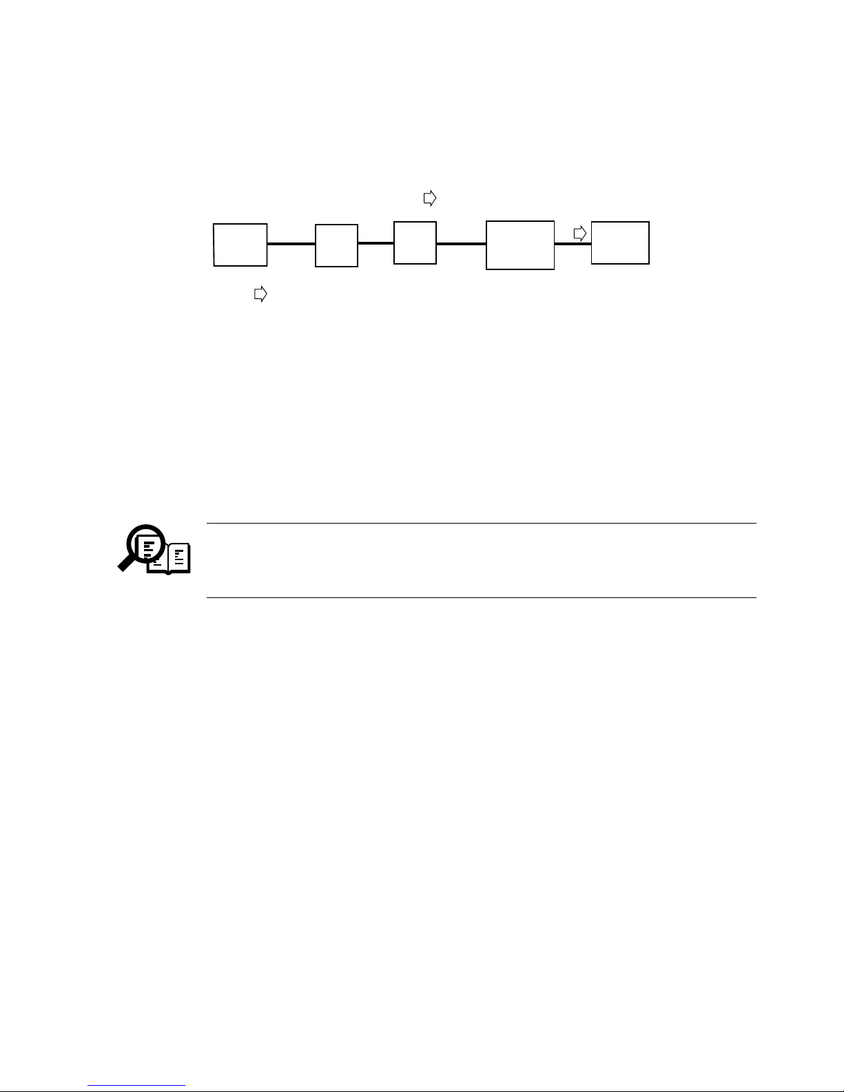
This mechanism is designed to automatically cammunicate (ECM) printer information,
e.g., cartridge replacement, printer number.
All Bits of the other machine’s DIS must be set to [1]; in other words, the presence of a single
[0] will cause the communication to end in error.
Bit 27 ECM: [0]=Not Provided, [1]=Provided
Bit 53 Binary File Transmission (BFT): [0]=Not Provided, [1]=Provided
Bit 99 Simple Phase C BFT Negotiations capability
: [0]=Not Provided, [1]=Provided
The communication will end normally if the other party returns MCF in
response to PPS-EOP. If, however, the other machine has a problem in
compatibility in relation to BFT, it will retur n FDM and the communication will
end in error.
NOTE
Printer information
Forwarding of data only
FAX-L360
FAX
Win 2000
English
(BFT recive)
PSTN
Sever

11
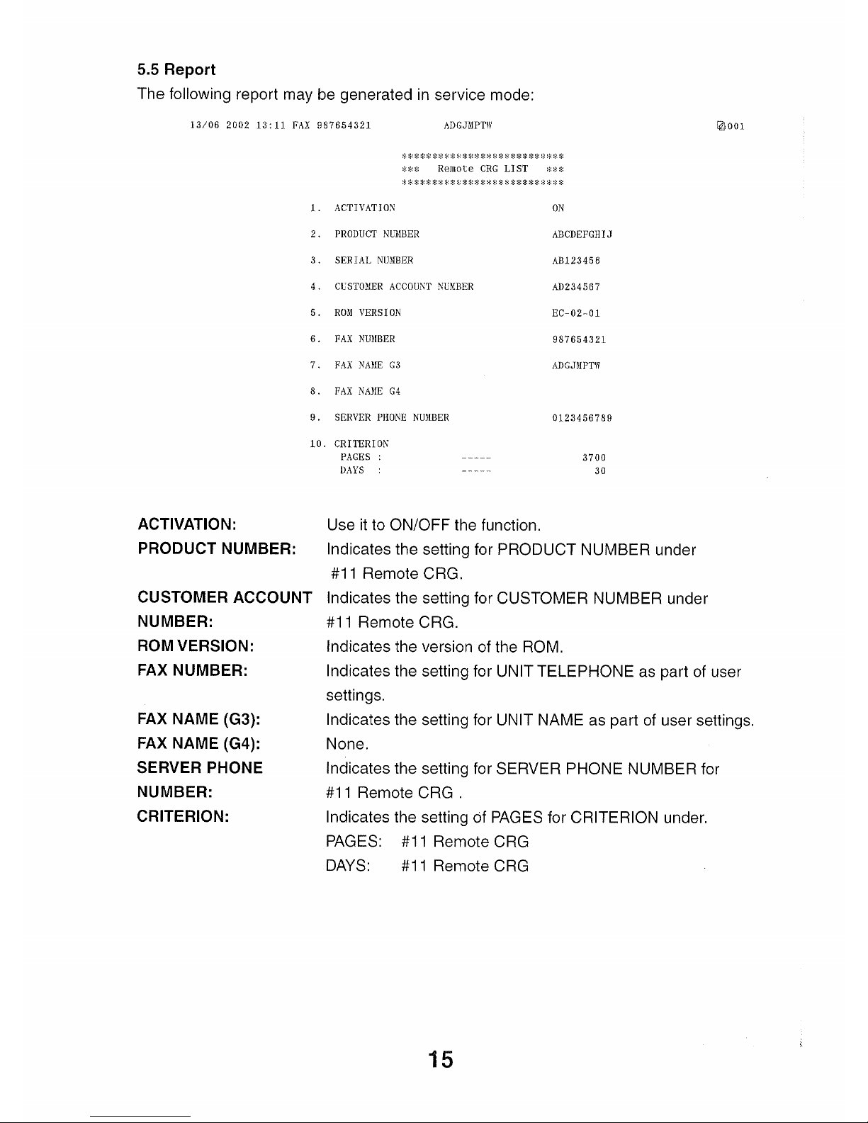
5.2 Setting
The following items are available according to service mode settings:
ACTIVATION: Use it to ON/OFF the function.
PRODUCT NUMBER: Use it to register a product number (10 characters;upper case,
lower case; numerals; symbols).
SERIAL NUMBER: Use it to register a serial number (8 characters;upper case,
lower case; numerals; symbols).
CUSTOMER NUMBER: Use it to register a serial number (8 characters;upper case,
lower case; numerals; symbols).
SERVER PHONE NBR: Use it to register the telephone number of the contact
(25 characters; numerals; tone; pause; space).
CRITERION: Use it to store information about the cause of a call.
PAGES: number of prints (3700; 0-9999)
DAYS: number of days passed (30; 0-9999)
REPORT: Use it to generate a report of BFT registration data issued.
MANUAL TX: Use it to manually transmit BFT registration data.
CLEAR: Use it to clear all parameters set under Remote CRG.
#11 Remote CRG ACTIVATION
PRODUCT NUMBER
SERIAL NUMBER
CUSTOMER NUMBER
SERVER PHONE NBR
CRITERION
REPORT
CLEAR
MANUAL TX
12
5.3 Conditions for a Call
The function is enabled when ACTIVATION is set to ON, and the number of prints and the
date currently registered will server as its starting point.
Condition 1:
When as many prints as set for PAGES under CRITERION have been made.
Condition 2:
When the cartridge runs out of toner, requiring replacement.
Condition 3:
When as many days as set for DAYS under CRITERION have been made.
Condition 4:
When a service error related to the printer has occurred.
A log on the following is used for the execution of this function:
Total number of prints made by the printer.
Number of prints that previously satisfied condition 1.
Date/Number of prints that previously satisfied condition 3.
Executing ALL CLEAR or CLEAR for Remote CRG will also clear the log data.
Condition 1:
When the difference between the number of prints and the number of prints that previously
satisfied condition 1 reaches the registered number of prints, a BFT file will be prepared and
a call made.
If the registered number of days under condition 3 is [0], no call will be made
under this condition.
Condition 2:
When the cartridge runs out of toner to require replacement, a call will be made.
Thereafter, no call will be made under condition 2 until the cartridge has been replaced and
the power has been turned off and then on. However, if condition 2 occurs once again when
the power is turned on after replacement of the cart r idge, a call will be made.
NOTE
NOTE
13
Condition 3:
When as many days as set pass since the day on which condition 3 is satisfied and, in
addition, when 12 hours pass since the time at which ACTIVATION is set to ON, a call
will be made.
If the registered number of days under condition 3 is [0], no call will be made
under this condition.
Condition 4:
When a service error that is related to the printer occurs, call will be made.
Thereafter, no call will be made under condition 4 unless the error has been cleared and the
power has been turned off and then on once again. However, if condition 4 occurs when the
power is turned on once again after clearing of the error, a call will be made.
If a connection to the target machine fails when transmitting a BFT file, a shift
will be made to redialing mode. Redialing may be enabled/disabled, and the
number of redialing sessions depends on user settings.
NOTE
NOTE
14
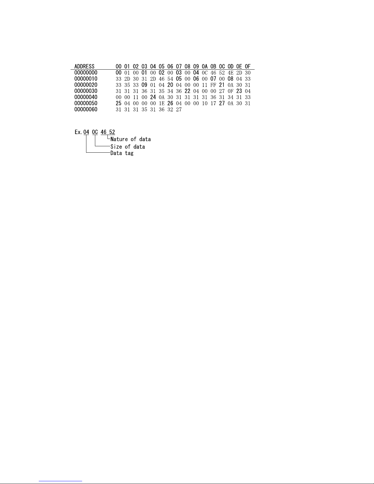
5.4 BFT File
A BFT file is constructed as follows:
00 call item 1: program version (fixed).
01 call item 2: product number (in ASCII).
02 call item 3: serial number (in ASCII).
03 call item 4: customer number (in ASCII).
04 call item 5: ROM version (in ASCII).
05 call item 6: FAX number (in ASCII).
06 call item 7: FAX name G3 (in ASCII).
07 call item 8: FAX name G4 (in ASCII).
08 call item 9: Server phone number (in ASCII).
09 call item 10: cause of call.
00: call condition 1.
01: call condition 2.
02: call condition 3.
03: call condition 4.
04: manual transmission.
20 call item 11: total number of prints (hexadecimal).
21 call item 12: date of transmission (in ASCII).
e.g., 2001 11 16 15:46 ---> 30 31 31 31 31 36 31 35 34 36
22 call item 13: number of prints set for PAGES under CRITERION (condition 1).
23 call item 14: number of prints when a call was made most recently under
condition 1.
24 call item 15: date on which a call was made most recently under condition 1.
25 call item 16: number of days set for DAYS under CRITERION (condition 3).
26 call item 17: number of prints when a call was made most recently under
condition 3.
27 call item 18: date on which a call was made most recently under condition 3.
 Loading...