

Canon DU7-1101-000, imageRUNNER 600 Service Manual

ADF FOR
imageRUNNER 600
SERVICE
MANUAL
REVISION 0
JAN. 1999
COPYRIGHT © 1999 CANON INC. CANON ADF FOR iR600 REV.0 JAN. 1999 PRINTED IN JAPAN (IMPRIME AU JAPON)
DU7-1101-000

IMPORTANT
THE INFORMATION CONTAINED HEREIN IS PUBLISHED BY CANON, INC., JAPAN.
SPECIFICATIONS AND OTHER INFORMATION CONTAINED HEREIN MAY DIFFER SLIGHTLY FROM
ACTUAL MACHINE VALUES OR THOSE FOUND IN ADVERTISING AND OTHER PRINTED MATTER.
ANY QUESTIONS REGARDING INFORMATION CONTAINED HEREIN SHOULD BE DIRECTED TO THE
COPIER SERVICE DEPARTMENT OF THE COMPANY.
COPYRIGHT 1999 CANON INC.
Printed in Japan
Imprimé au Japon
Use of this manual should be strictly
supervised to avoid disclosure of confi-
dential information.
Prepared by
OFFICE IMAGING PRODUCTS TECHNICAL SUPPORT DIVISION
CANON INC.
5-1, Hakusan 7-chome, Toride, Ibaraki, 302-8501 Japan
COPYRIGHT © 1999 CANON INC. CANON ADF FOR iR600 REV.0 JAN. 1999 PRINTED IN JAPAN (IMPRIME AU JAPON)

INTRODUCTION
This Service Manual contains basic data and figures on the ADF for the iR600 needed
to service the machine in the field.
CHAPTER 1 General Description introduces the ADF's features and specifications,
and shows how to operate the ADF.
CHAPTER 2 Basic Operation provides outlines of the ADF's various mechanical
workings, and explains the principles used for the ADF's various control mechanisms in
view of the functions of electrical and mechanical units and in relation to their timing of
operation.
CHAPTER 3 Mechanical System shows how the ADF's various mechanical workings
are constructed, and how the ADF may be disassembled/assembled and adjusted.
CHAPTER 4 Maintenance and Servicing provides tables of periodically replaced
parts and consumables/durables and scheduled servicing charts.
CHAPTER 5 Troubleshooting provides tables of maintenance/inspection, standards/
adjustments, and problem identification (image fault/malfunction).
APPENDIX contains a general timing chart and general circuit diagrams.
The descriptions in this Service Manual are subject to change without notice for
product improvement or other purposes, and major changes will be communicated in the
form of Service Information bulletins.
All service persons are expected to have a good understanding of the contents of this
Service Manual and all relevant Service Information bulletins and be able to identify and
isolate faults in the machine.
COPYRIGHT © 1999 CANON INC. CANON ADF FOR iR600 REV.0 JAN. 1999 PRINTED IN JAPAN (IMPRIME AU JAPON)
i

CONTENTS
CHAPTER 1 GENERAL DESCRIPTION
I . FEATURES ..................................1-1
II . SPECIFICATIONS ....................... 1-2
A. ADF for iR600........................ 1-2
III . NAMES OF PARTS ....................1-4
A. External View ........................ 1-4
B. Cross Section ........................ 1-5
CHAPTER 2 OPERATIONS
I . BASIC CONSTRUCTION............. 2-1
A. Electrical Circuitry ................. 2-1
B. Communication with the Copier
.............................................. 2-1
C. Inputs to the ADF Controller PCB
.............................................. 2-2
D. Outputs from the ADF Controller
PCB....................................... 2-4
II . BASIC OPERATIONS ................. 2-5
A. Outline ...................................2-5
B. Operations ............................. 2-8
1. Outline .............................. 2-8
2. CWW Pickup/Delivery ...... 2-8
3. Pre-Reversal Pickup,
Reversal, Delivery (small-size
original) ............................ 2-9
4. Reversal Pickup, Reversal,
Delivery (large-size original)
....................................... 2-11
5. Manual Feeder Pickup/
Delivery .......................... 2-13
C. Detecting an Original........... 2-14
1. Outline ............................ 2-14
2. Detecting the Presence/
Absence of an Original ...2-15
3. Original Size Detection 1
....................................... 2-16
4. Original Size Detection 2
....................................... 2-17
5. Pre-Last Original Detection
....................................... 2-22
6. Detecting the Presence/
Absence of an Original in the
Manual Feed Assembly .. 2-23
IV . OPERATION .............................. 1-6
A. Original Set Indicator .............1-6
B. Warnings and Actions to Take
.............................................. 1-6
C. Routine Maintenance by the User
.............................................. 1-7
D. Original Pickup/Separation.. 2-24
1. Outline ............................ 2-24
2. Moving Up/Down the Pickup
Roller Units .................... 2-25
3. Switching the Separation
Pressure ......................... 2-28
4. Separation Sensor (S4),
Skew Sensor (S5) .......... 2-29
5. Controlling the Pickup Motor
(M3) ................................ 2-31
6. Controlling the Separation
Motor (M4) ...................... 2-32
7. Sequence of Operations
....................................... 2-33
E. Feeding/Delivering Originals
............................................ 2-34
1. Outline ............................ 2-34
2. Controlling the Belt Motor (M2)
2-35
3. Controlling the Delivery Motor
(M5) ................................ 2-36
F. CW Rotation Pickup/Delivery
............................................ 2-37
1. Outline ............................ 2-37
2. Fixing Reading Mode ..... 2-37
3. Stream Reading ............. 2-46
G. Pre-Reversal Pickup/Delivery
............................................ 2-55
1. Outline ............................ 2-55
2. Operation ........................ 2-55
H. Reversal Pickup/Delivery .... 2-61
1. Outline ............................ 2-61
2. Operation ........................ 2-61
COPYRIGHT © 1999 CANON INC. CANON ADF FOR iR600 REV.0 JAN. 1999 PRINTED IN JAPAN (IMPRIME AU JAPON)

3. Controlling the Reversal Motor
(M1) ................................ 2-65
4. Sequence of Operations
(large-size, double-sided
original) ..........................2-67
I. Manual Feeder Pickup/Delivery
............................................ 2-69
CHAPTER 3 MECHANICAL SYSTEM
1. Operation........................ 2-69
2. Sequence of Operations
....................................... 2-71
III . DETECTING JAMS .................. 2-72
IV . POWER SUPPLY .................... 2-79
I . BASIC CONSTRUCTION............. 3-1
A. External Covers ..................... 3-1
1. Removing the Machine..... 3-1
2. Removing the Lower Front
Cover ................................ 3-2
3. Removing the Front Cover
......................................... 3-2
4. Removing the Main Cover
......................................... 3-3
5. Removing the Original Tray
......................................... 3-4
6. Removing the Upper Cover
......................................... 3-5
7. Removing the ADF Controller
Cover ................................ 3-5
8. Side Guide Lock ............... 3-6
II . DRIVE SYSTEM .......................... 3-7
1. Removing the Reversal Motor
Unit ................................... 3-7
2. Removing the Separation
Motor Unit ......................... 3-7
3. Removing the Pickup Motor
Unit ................................... 3-8
4. Removing the Belt Motor Unit
......................................... 3-9
5. Removing the Delivery Motor
....................................... 3-10
III . FEEDING SYSTEM .................. 3-12
1. Removing the Delivery Roller
....................................... 3-12
2. Removing the Pickup Roller
....................................... 3-14
3. Removing the Separation
Roller.............................. 3-15
4. Removing the Manual Feed
Registration Roller ......... 3-19
5. Removing the Feeding (pull-
out) Roller ....................... 3-21
6. Removing the Registration
Roller.............................. 3-23
7. Removing the Separation Belt
....................................... 3-24
8. Removing the Reversing
Roller.............................. 3-27
IV. REPLACING THE FEEDING BELT
................................................. 3-30
1. Removing the Feeding Belt
....................................... 3-30
2. Mounting the Feeding Belt
....................................... 3-32
CHAPTER 4 MAINTENANCE AND SERVICING
I . PERIODICALLY REPLACED
PARTS ....................................... 4-1
II . DURABLES ............................... 4-1
III . SCHEDULED SERVICING CHART
................................................... 4-2
COPYRIGHT © 1999 CANON INC. CANON ADF FOR iR600 REV.0 JAN. 1999 PRINTED IN JAPAN (IMPRIME AU JAPON)
IV . CLEANING ................................. 4-4
A. Copyboard Glass................... 4-4
B. Belt Assembly........................ 4-4
C. Sensors ................................. 4-5

CHAPTER 5 TROUBLESHOOTING
I . STANDARDS AND ADJUSTMENTS
................................................... 5-1
A. Basic Adjustments ................. 5-1
1. Adjusting the Height of the
ADF .................................. 5-1
2. Adjusting the Orientation of
the ADF ............................5-2
3. Removing the Skew ......... 5-4
4. Adjusting the Horizontal
Registration .................... 5-15
5. Adjusting the Original Stop
Position .......................... 5-20
B. Making Adjustments When
Replacing Major Parts ......... 5-26
1. Outline ............................ 5-26
2. Replacing the EEPROM
....................................... 5-27
3. Adjusting the Sensor and the
Delivery Motor ................ 5-28
C. Auxiliary Adjustments .......... 5-32
1. Adjusting Registration Roller
Pickup Arching for Tray
Pickup
Adjusting Registration Roller
Arching for Reversal
Adjusting Registration Roller
Pickup Arching for Manual
feed Pickup .................... 5-32
2. Adjusting the Speed of the
Belt .................................5-34
3. Adjusting the Speed of
Reversal ......................... 5-36
4. Checking the Sensor Output
....................................... 5-39
D. Indication ............................. 5-41
1. Jam Counter ...................5-41
2. Tray Pickup Counter/Manual
Feed Pickup Counter ..... 5-42
3. Jam History .................... 5-43
4. Software Version ............ 5-44
E. Cleaning .............................. 5-45
1. Cleaning the Separation
Assembly........................ 5-45
2. Cleaning the Registration
Roller.............................. 5-47
F. Others .................................. 5-49
1. Checking the Original Width
Detecting Switch (SW301)
....................................... 5-49
2. Initializing the Back-Up RAM
....................................... 5-50
3. Setting Mix Size Mode .... 5-51
II . TROUBLESHOOTING ............. 5-57
A. Troubleshooting Malfunctions
............................................ 5-57
1. E402 ............................... 5-57
2. E404 ............................... 5-59
3. E405 ............................... 5-60
4. E410 ............................... 5-61
5. E422 ............................... 5-62
III . ARRANGEMENT OF ELECTRICAL
PARTS ..................................... 5-63
A. Sensors ............................... 5-63
B. Motors, Clutches, and Solenoids
............................................ 5-64
C. PCBs ................................... 5-65
IV . LEDS, CHECK PINS, AND
SWITCHES BY PCB ................ 5-66
A. ADF Controller PCB ............ 5-66
1. Arrangement of Parts ...... 5-66
2. DIP Switch Settings and
Functions........................ 5-67
B. Reversal Motor Driver PCB . 5-71
C. Belt Motor Driver PCB ......... 5-71
D. Pickup Tray PCB ................. 5-72
E. Indicator LED PCB .............. 5-72
V . SELF DIAGNOSIS ................... 5-73
A. Outline ................................. 5-73
B. Alarm ................................... 5-74
C. Jams .................................... 5-74
D. Errors................................... 5-75
APPENDIX
A. General Timing Chart ........... A-1
B. Signals and Abbreviations ... A-9
C. General Circuit Diagram..... A-11
COPYRIGHT © 1999 CANON INC. CANON ADF FOR iR600 REV.0 JAN. 1999 PRINTED IN JAPAN (IMPRIME AU JAPON)
D. ADF Controller Circuit Diagram
........................................... A-13

E. Reversal Motor Driver Circuit
Diagram .............................. A-25
F. Belt Motor Driver Circuit Diagram
........................................... A-26
G. Reversal Sensor Circuit Diagram
........................................... A-27
H. Pre-/Post-Registration Roller
Sensor Circuit Diagram ...... A-28
I. Separation Sensor/Skew Sensor
Circuit Diagram .................. A-29
J. Original Sensor (light-emitting)
Circuit Diagram .................. A-30
K. Original Sensor (light-receiving)
Circuit Diagram .................. A-30
L. Tray Circuit Diagram .......... A-31
M. Pre-Last Original Paper Sensor
Circuit Diagram .................. A-33
N. Original Set Indicator Circuit
Diagram .............................. A-33
O. Manual Feed Registration Roller
Paper Sensor Circuit Diagram
........................................... A-34
P. Special Tools ..................... A-35
Q. Solvents and Oils List ......... A-35
COPYRIGHT © 1999 CANON INC. CANON ADF FOR iR600 REV.0 JAN. 1999 PRINTED IN JAPAN (IMPRIME AU JAPON)

CHAPTER 1
GENERAL DESCRIPTION
I . FEATURES .................................. 1-1
II . SPECIFICATIONS....................... 1-2
A. ADF for iR600........................ 1-2
III . NAMES OF PARTS ....................1-4
A. External View ........................ 1-4
B. Cross Section ........................ 1-5
COPYRIGHT © 1999 CANON INC. CANON ADF FOR iR600 REV.0 JAN. 1999 PRINTED IN JAPAN (IMPRIME AU JAPON)
IV . OPERATION .............................. 1-6
A. Original Set Indicator .............1-6
B. Warnings and Actions to Take
.............................................. 1-6
C. Routine Maintenance by the User
.............................................. 1-7

CHAPTER 1 GENERAL DESCRIPTION
I . FEATURES
1. First Page First
The machine helps increase its host copier's productivity (if the copier possesses a reversing mecha-
nism).
2. Pre-Reversing Mechanism
The machine's pre-reversing mechanism adds to productivity when processing double-sided origi-
nals.
3. Clip-On Feeding Belt Unit
Compared with the exiting models, the machine's feeding belt can be removed much more easily,
facilitating servicing work.
4. Stream Reading of All Sizes
The machine may use stream reading for all sizes (including large size) of originals (for reproduction
ratios between 50% and 150%).
COPYRIGHT © 1999 CANON INC. CANON ADF FOR iR600 REV.0 JAN. 1999 PRINTED IN JAPAN (IMPRIME AU JAPON)
1-1

CHAPTER 1 GENERAL DESCRIPTION
II . SPECIFICATIONS
A. ADF for imageRUNNER 600
Item
Pickup
Original placement
Original position
Original separation
Original type
Original size
Original tray
Original delivery tray
Original processing
Stream reading
Manual feed
Original size identification
Residual paper detection
Size mixing
Book original
Specifications
Auto pickup/delivery
Original tray: face up
Manual feeder: face down
Original tray: center
Manual feeder: rear stop
Top separation
Sheet
Original tray: 50 to 200 g/m
Manual feeder: 38 to 200 g/m
2
2
A5 to A3/STMT to 279.4×431.8mm
(11"×17")
Small size: 100 sheets
A5, A4, B5, STMT, LTR, A4R, B5R,
LTRR
Large size: 50 sheets
A3, B4, LGL, 279.4×431.8 mm (11"×17")
Small size: 100 sheets
A5, A4, B5, STMT, LTR, A4R, B5R,
LTRR
Large size: 50 sheets
A3, B4, LGL, 279.4×431.8 mm (11"×17")
Single-sided, double-sided
Provided (all sizes; single-sided, between
50% and 150%)
Provided (single sheet only)
Provided (default sizes only)
Provided
Provided (same feeding width only)
Supported (40 mm or less in thickness)
Remarks
However, 163 g/m2 if largesize, double-sided copies.
For paper of 80 g/m2 or
less.
For paper of 80 g/m2 or
less.
For paper of 80 g/m2 or
less.
For paper of 80 g/m2 or
less.
1-2
Table 1-202-1
COPYRIGHT © 1999 CANON INC. CANON ADF FOR iR600 REV.0 JAN. 1999 PRINTED IN JAPAN (IMPRIME AU JAPON)

CHAPTER 1 GENERAL DESCRIPTION
Item
Communication with
copier
Power supply
Weight
Dimensions
Serial No.
Operating environment
Temperature range
Humidity range
The above specifications are subject to change for product improvement.
Specifications
IPC communication 2
24 VDC (from copier)
21 kg (approx.)
646 (W) × 569.5 (D) × 143 (H) mm
A: ZRBxxxxx
Inch/A: ZRCxxxxx
AB: ZRDxxxxx
Inch/AB: ZRExxxxx
Same as copier.
Table 1-202-2
Remarks
Not including delivery tray.
Not including delivery tray.
COPYRIGHT © 1999 CANON INC. CANON ADF FOR iR600 REV.0 JAN. 1999 PRINTED IN JAPAN (IMPRIME AU JAPON)
1-3
CHAPTER 1 GENERAL DESCRIPTION
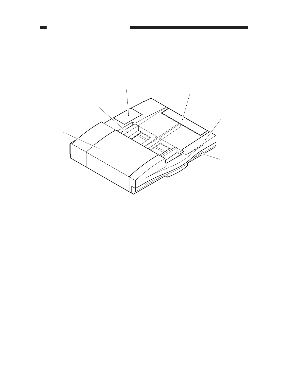
III . NAMES OF PARTS
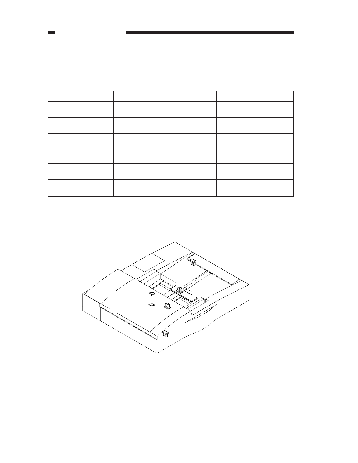
A. External View
[3]
[2]
[1]
[4]
[5]
[6]
[1] Upper cover
[2] Side guide
[3] ADF controller cover
1-4
COPYRIGHT © 1999 CANON INC. CANON ADF FOR iR600 REV.0 JAN. 1999 PRINTED IN JAPAN (IMPRIME AU JAPON)
[4] Manual tray
[5] Upper front cover
[6] Lower front cover
Figure 1-301
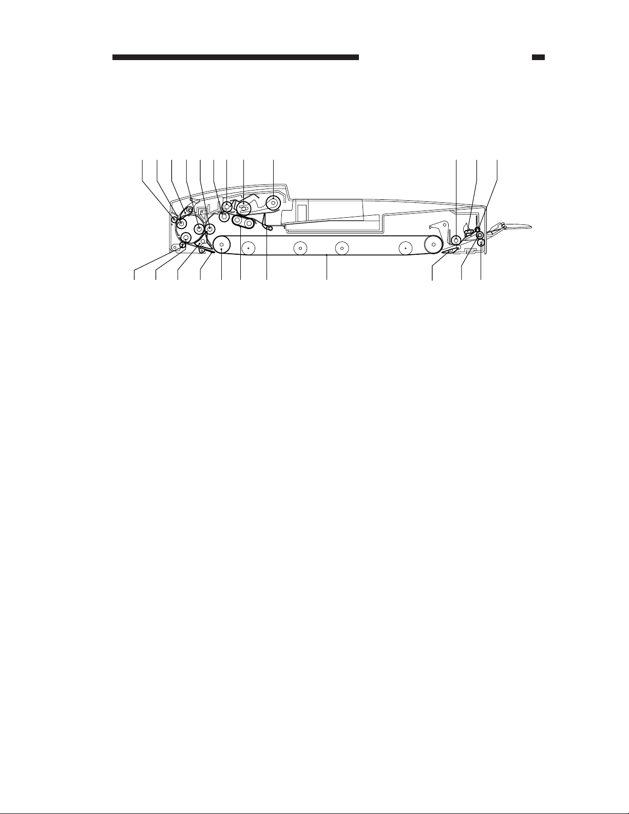
B. Cross Section
CHAPTER 1 GENERAL DESCRIPTION
[1][2] [3] [4][5][6][7] [8] [9]
[18]
[19][20][21][23] [22]
[1] Reversing roller B roll
[2] Reversing roller B
[3] Reversing flapper
[4] Registration locking roller
[5] Registration roller
[6] Pull-out roller
[7] Pull out locking roller
[8] Feeding roller
[9] Pickup roller
[10] Manual feed registration roller
[11] Manual feed stopper plate
[12] Delivery roller A roll
[17]
[16]
[13]Delivery roller B roll
[14]Delivery roller
[15]Delivery jumping flapper
[16]Feeding belt
[17]Stopper plate
[18]Separation belt
[19]Feeding belt drive roller
[20]Jumping flapper
[21]Pre-reversal flapper
[22]Reversing roller A
[23]Reversing roller A roll
[10][11][12]
[15] [14][13]
Figure 1-302
COPYRIGHT © 1999 CANON INC. CANON ADF FOR iR600 REV.0 JAN. 1999 PRINTED IN JAPAN (IMPRIME AU JAPON)
1-5

CHAPTER 1 GENERAL DESCRIPTION
IV . OPERATION
A. Original Set Indicator
The Original Set indicator turns on when an original is placed on the original tray, and flashes when an
original jams.
Original Set indicator
Figure 1-401
B. Warnings and Actions to Take
Suspect a jam if the Original Set indicator starts to flash while an original is being fed. Perform the
following steps for correction:
1) Remove all originals from the original tray.
2) Open the upper cover, and remove the jam, if any.
3) Open the ADF, and remove the original, if any, from the copyboard.
4) Put the originals in correct order, and set the stack in the ADF.
1-6
COPYRIGHT © 1999 CANON INC. CANON ADF FOR iR600 REV.0 JAN. 1999 PRINTED IN JAPAN (IMPRIME AU JAPON)

C. Routine Maintenance by the User
Instruct the user to clean the following parts at least once a week.
CHAPTER 1 GENERAL DESCRIPTION
Parts
Copyboard glass
Feeding belt
Registration roller
Description
Wipe it with a cloth moistened with water or alcohol; then, dry wipe it.
Wipe it with a cloth moistened with water or alcohol; then, dry wipe it.
Execute the copier's user mode.
Table 1-401
COPYRIGHT © 1999 CANON INC. CANON ADF FOR iR600 REV.0 JAN. 1999 PRINTED IN JAPAN (IMPRIME AU JAPON)
1-7

CHAPTER 2
Operations
1. In outline diagrams,
and
2. Signals in digital circuits are identified as '1' for High and '0' for Low. The
voltage of signals, however depends on the circuit.
Nearly all operations of the machine are contorolled by the CPU; the internal
workings of the CPU are not relevant to the service person's work and, therefore,
are left out of the discussions. By the same token, no repairs are prescribed for the
PCBs at the user's premises; for this reason, PCBs are discussed by means of
block diagrams rather than circuit diagrams.
For the purpose of explanation, discussions are divided into the following: from
sensors to ADF controller PCB input ports; from ADF controller output ports to
loads; and minor control circuits and functions.
indicates electrical signal paths.
represents mechanical drive paths,
I . BASIC CONSTRUCTION............. 2-1
A. Electrical Circuitry ................. 2-1
B. Communication with the Copier
.............................................. 2-1
C. Inputs to the ADF Controller PCB
.............................................. 2-2
D. Outputs from the ADF Controller
PCB....................................... 2-4
II . BASIC OPERATIONS ................. 2-5
A. Outline ................................... 2-5
B. Operations ............................. 2-8
C. Detecting an Original........... 2-14
COPYRIGHT © 1999 CANON INC. CANON ADF FOR iR600 REV.0 JAN. 1999 PRINTED IN JAPAN (IMPRIME AU JAPON)
D. Original Pickup/Separation.. 2-24
E. Feeding/Delivering Originals
............................................ 2-34
F. CW Rotation Pickup/Delivery
............................................ 2-37
G. Pre-Reversal Pickup/Delivery
............................................ 2-55
H. Reversal Pickup/Delivery .... 2-61
I. Manual Feeder Pickup/Delivery
............................................ 2-69
III . DETECTING JAMS .................. 2-72
IV . POWER SUPPLY .................... 2-79
CHAPTER 2 OPERATIONS
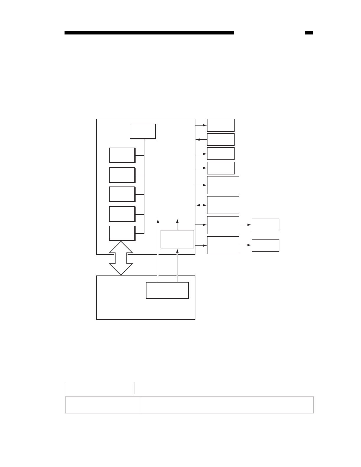
I . BASIC CONSTRUCTION
A. Electrical Circuitry
The machine's electrical mechanisms are controlled by the ADF controller PCB. The CPU on
the ADF controller PCB interprets input signals from the machine's sensors and the host copier, and
generates signals to drive the motors, solenoids, and other DC loads.
ADF controller PCB
ROM
(IC1)
EEPROM
(IC2)
RAM
(Q4)
D/A
(Q9)
IPC
(Q2)
CPU
(Q1)
+5V+24R
5 VDC power
supply (Q28)
Power supply
PCB
Motor
Sensor
Solenoid
Clutch
Original
indicator
LD PCB
Tray PCB
Reversal
motor
driver PCB
Belt motor
driver PCB
Motor
Motor
Copier
Figure 2-101
B. Communication with the Copier
The machine communicates using IPC communication 2, which enables communication at a
higher speed than the existing IPC methods.
Related Error Code
E422
E712
COPYRIGHT © 1999 CANON INC. CANON ADF FOR iR600 REV.0 JAN. 1999 PRINTED IN JAPAN (IMPRIME AU JAPON)
A fault has occurred in the communication with the copier.
2-1
CHAPTER 2 OPERATIONS
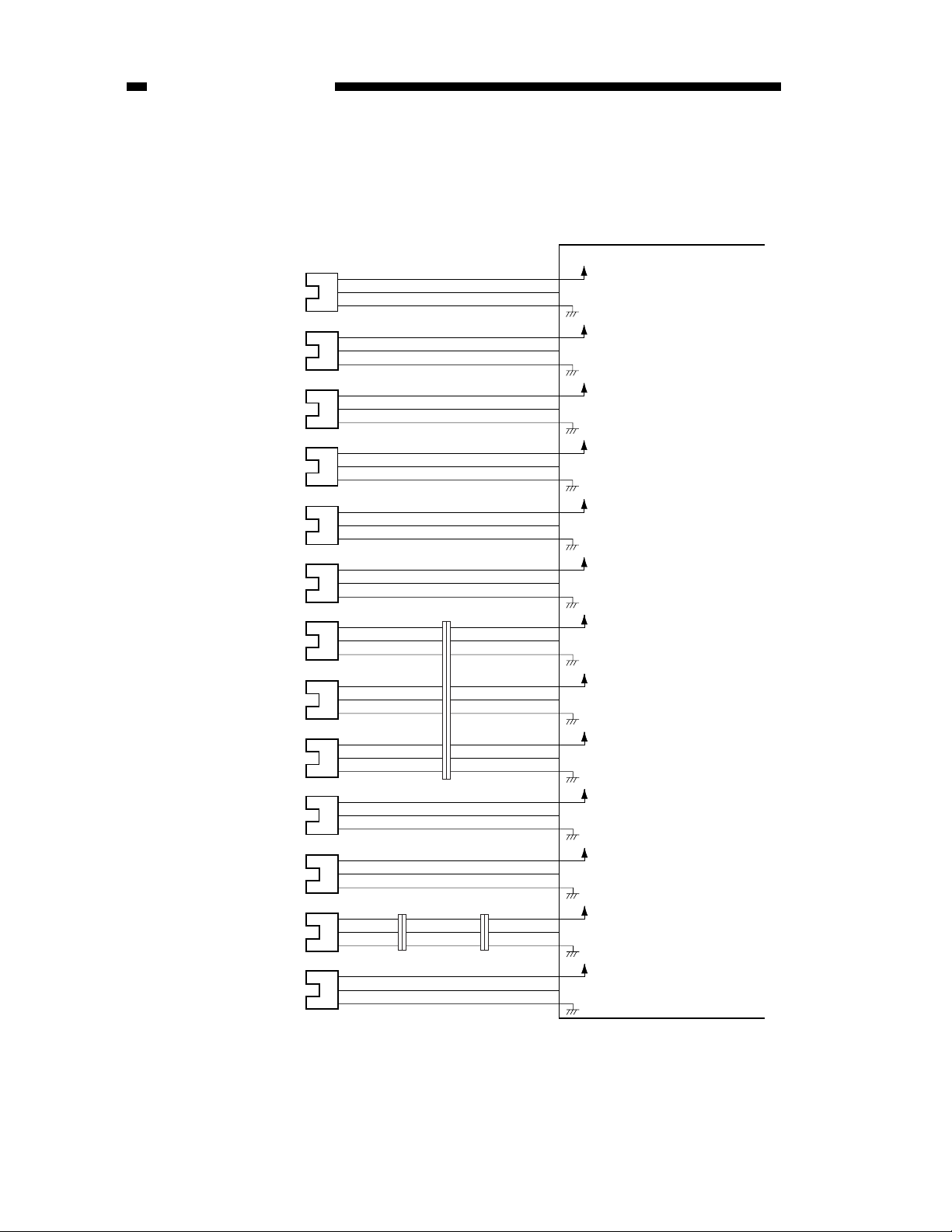
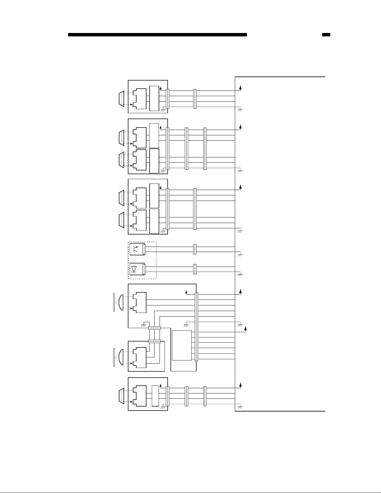
C. Inputs to the ADF Controller PCB
Inputs to the ADF Controller PCB (1/2)
Belt motor clock
sensor
Separation motor
clock sensor
Left cover sensor
(rear)
Pre-reversal sensor
Registration roller
clock sensor
Left cover sensor
(front)
Pickup roller home
position sensor
Pickup roller height
sensor 1
Pickup roller height
sensor 2
ADF open/closed
sensor
Delivery motor clock
sensor
Manual feed sensor
Original delivery
sensor
PI 1
PI 2
PI 3
PI 4
PI 5
PI 6
PI 7
PI 8
PI 9
PI 10
PI 11
PI 12
PI 13
J141
-1
-9
-3
-7
-2
-8
-4
-6
-6
-4
-5
-5
-3
-7
-1
-9
-2
-8
J21J23
-5
-3
-5
-1
-7
-2
-6
-10
-8
-3
-4
-9
J12-1
J12-6
J12-7
J12-10
-12
-11
J14-B8
-B10
-B9
J14-B5
-B7
-B6
J14-A3
-A5
-A4
J14-A6
-A8
-A7
J14-A9
-A11
-A10
J12-13
-15
-14
J3-3
J2-8
-10
J2-13
-15
-14
ADF controller PCB
+5V
-3
-2
-5
-4
-9
-8
-2
-1
-9
BTCLK
SPCLK
LCVR
PRTR
TRCLK
LCVF
PKHP
PKH1
PKH2
RFOP
EJCLK
MFST
EJJAM
Pulses according to
the speed of the belt
+5V
motor.
Pulses according to
the speed of the
+5V
separation motor.
When the left cover is
closed, '1'.
+5V
When paper is
present, '1'.
+5V
Pulses according to
the speed of the
+5V
registration roller.
When the left cover is
closed, '1'.
+5V
When the pickup roller
is in the home
+5V
position, '1'.
When the pickup roller
is on paper, '1'.
+5V
When the pickup roller
is on paper, '1'.
+5V
When the ADF is
closed, '1'.
+5V
Pulses according to
the speed of the
+5V
delivery motor.
When paper is
present, '1'.
+5V
When paper is
present, '1'.
2-2
Figure 2-102
COPYRIGHT © 1999 CANON INC. CANON ADF FOR iR600 REV.0 JAN. 1999 PRINTED IN JAPAN (IMPRIME AU JAPON)
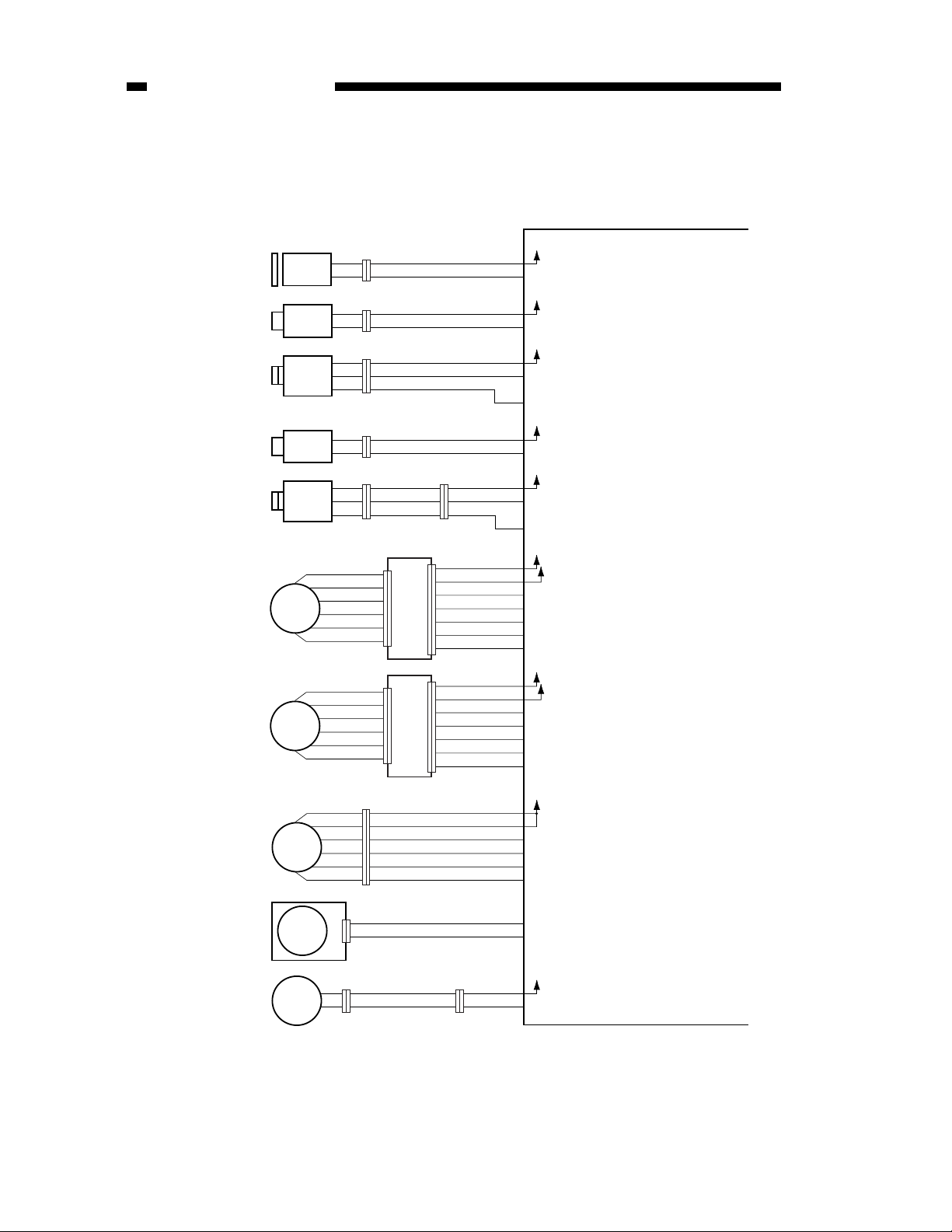
Inputs to the ADF Controller PCB (2/2)
+5V
Reversal
sensor
Pre-registration
paper sensor
Post-registration
paper sensor
Separation
sensor
Skew sensor
Original sensor
(light-receiving)
Original sensor
(light-emitting)
Original trailing
edge sensor
Copy paper
Pre-last original
paper sensor
S1
S2
S3
S4
S5
S6
S7
J52-2 -3 -1
J56-2 -1 -3
S8
Comparator
Comparator
Comparator
Comparator
Comparator
-2
-1
-2
-1
circuit
+5V
circuit
circuit
+5V
circuit
circuit
Tray PCB
-4
-1
-2
-3
-6
-1
-1
-6
-2
-5
-3
-4
-4
-3
-5
-2
-1
-6
-5
-4
-3
-2
Original
width
detecting
switch
SW301
CHAPTER 2 OPERATIONS
ADF controller PCB
+5V
-4
-1
-1
-4
-2
-3
-3
-2
J144J149
J14-B1
-B4
-B3
-B2
TNSAJ
TNS
Paper reference signal
When paper is present,
'0'.
+5V
-1
-6
-3
-6
-5
-4
-5
-3
RGBSAJ
-4
RGBS
Paper reference signal
When paper is present,
J13-8
-1
-8
'0'.
-4
-5
-4
-3
-6
-3
-2
-7
-2
J133 J132J135
-5
RGASAJ
-6
RGAS
-2
Paper reference signal
When paper is present,
'0'.
+5V
-1
-6
-6
-1
-5
-2
J13-14
-10
-9
SPSAJ
SPS
Paper reference signal
When paper is present,
'0'.
-3
-4
-5
-1
-7
-1
-2
+5V
-4
-3
-2
J131J134
-8
-2
J132J136
-3
-2
J140J145
-2
-5
-4
-7
-6
-3
-13
-9
-10
-11
-12
-8
J51
-11
-12
-13
J13-2
J14-A1
-A2
J5-12
-10
-11
J51-1
SKSAJ
SKS
DTS
-1
DTSAJ
-9
TAILSAJ
TAILS
-7
LASAJ
-8
LAS
-5
SSW-0
-4
SSW-1
-3
SSW-2
-2
SSW-3
-6
SSW-4
+5V
+5V
Paper reference signal
When paper is present,
'0'.
When paper is present,
'0'.
Paper reference signal
Paper reference signal
When paper is present,
'0'.
Paper reference signal
When paper is present,
'0'.
Signal according to
paper width. (For
details, see p. 2-17.)
Copy paper
Manual feeder
registration
roller paper
sensor
S9
+5V
-9
-1
-4
-4
-1
-3
-2
-2
-3
-4
-7
-6
-7
-4
-7
-6
-5
-8
-5
-6
J23 J21J25
J2-4
-7
-6
-5
+5V
MFRGSAJ
MFRGS
Paper reference signal
When paper is present,
'0'.
Figure 2-103
COPYRIGHT © 1999 CANON INC. CANON ADF FOR iR600 REV.0 JAN. 1999 PRINTED IN JAPAN (IMPRIME AU JAPON)
2-3
CHAPTER 2 OPERATIONS
D. Outputs from the ADF Controller PCB
Outputs from the ADF Controller PCB (1/1)
+24V
-12
-11
-10
-9
-8
-9
J10-3
J9-1
J9-3
J10-1
J2-1
J6-8~10
J7-9~11
J11-1
-4
CLD
+24V
-2
SL1D
+24V
-4
SL2D1
-5
SL2D2*
+24V
-2
SL3D
+24V
-2
SL4D1
-3
SL4D2*
+24V
-1
-2
M1OB*
-3
M1OA*
-4
M1OB
-5
M1OA
-6
T-Vref
+24V
-6
-1
REF-CLK
-2
MO1
-3
MO2
-4
CW/CCW
-5
B-Vref
+24V
-2
-3
M3OB
-4
M3OA*
-5
M3OB
-6
M3OA
Separation
clutch
Reversing
solenoid
Stopper plate
solenoid
(2 positions)
Pre-reversing
solenoid
Delivery
solenoid
(2 positions)
Reversal motor
Belt motor
Pickup motor
M1
M2
M3
CL
SL1
SL2
SL3
SL4
+24V
+24V
+24V
+24V
-2
-1
-1
-2
J102
-2
-1
-1
-2
J91
-3
-1
-2
-2
-1
-3
J92
-2
-1
-1
-2
J101
-3
-1
-2
-2
-1
-3
-1
-2
-3
A
-4
A
*
-5
B
-6
B
*
J602
-1
-2
-3
A
-4
A
*
-5
B
-6
B
*
J72
-1
-6
-2
-5
-3
-4
-4
-3
-5
-2
-6
-1
J111
-1
-2
-3
J21J22
-4~6
-13
-12
-11
-10
Reversal motor
driver PCB
J601
-4~6
-14
-13
-12
-11
Belt motor
driver PCB
-10
J71
Figure 2-104
ADF controller PCB
When '0', the
*
separation clutch turns
on.
When '0', the solenoid
*
turns on.
When '0', solenoid
*
turns on (position 1).
When '0', the solenoid
turns on (position 2).
When '0', the solenoid
*
turns on.
When '0', the solenoid
*
turns on (position 1)
When '0', the solenoid
turns on (position 2).
+5V
For details, see p. 2-65.
+5V
For details, see p 2-35.
*
For details, see p. 2-31.
Separation
motor
Delivery motor
2-4
M4
-2
-1
J81
J8-1
-2
SEPM+
SEPM-
For details, see p. 2-32.
+24V
M5
-2
-1
-1
-2
J24
-11
-12
J21
-2
-12
-1
EJMD
For details, see p. 2-36.
*
J2-11
Figure 2-104
COPYRIGHT © 1999 CANON INC. CANON ADF FOR iR600 REV.0 JAN. 1999 PRINTED IN JAPAN (IMPRIME AU JAPON)

CHAPTER 2 OPERATIONS
II . BASIC OPERATIONS
A. Outline
The machine uses five motors and one clutch for picking up, separating, feeding, and delivering
originals.
Name (notation)
Reversal motor (M1)
Belt motor (M2)
Pickup motor (M3)
Separation motor (M4)
Delivery motor (M5)
Separation clutch (CL)
Function
Moves or reverses originals.
Moves originals.
Moves up/down the pickup roller.
Separates originals.
Delivers originals or picks up manually fed originals.
Disengages or engages the pull-out roller
and separation/feeding assembly drive system.
Table 2-201
COPYRIGHT © 1999 CANON INC. CANON ADF FOR iR600 REV.0 JAN. 1999 PRINTED IN JAPAN (IMPRIME AU JAPON)
2-5

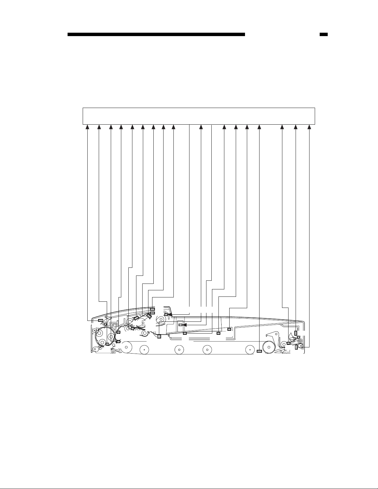
CHAPTER 2 OPERATIONS
Pre-reversing solenoid drive signal (SL1D)
Separation motor drive signal
Separation clutch drive signal (CLD)
Separation motor clock signal (SPCLK)
ADF controller PCB
Stopper plate solenoid drive signal 2 (SL2D2)
Stopper plate solenoid drive signal 1 (SL2D1)
Pickup motor drive signal
Belt motor drive signal
Belt motor clock signal (BTCLK)
Reversal motor drive signal
Reversing solenoid drive signal (SL3D)
Registration roller clock signal (TRCLK)
Delivery solenoid drive signal 1 (SL4D1)
Delivery solenoid drive signal 2 (SL4D2)
Delivery motor drive signal
Delivery motor clock signal (EJCLK)
SL1
M4
SL3
PI 2
PI 5
CL
SL2
M3
M2
PI 1
M1
Figure 2-201 Drive Diagram
SL4
M5
PI 11
2-6
COPYRIGHT © 1999 CANON INC. CANON ADF FOR iR600 REV.0 JAN. 1999 PRINTED IN JAPAN (IMPRIME AU JAPON)
ADF controller PCB
CHAPTER 2 OPERATIONS
Pre-reversal detection signal (PRTR)
Reversal paper detection signal (TNS)
PI4
Post-registration roller paper detection signal (RGAS)
S1
Separation paper detection signal (SPS) / skew paper
detection signal (SKS)
Pre-registration roller paper detection signal (RGBS)
S4,S5
S2
S3
Pickup roller home position signal (PKHP)
Pickup roller height 1 signal/2 signal (PKH1/ PKH2)
PI6
PI3
PI8,
PI7
PI9
S6 (light-receiving)
Left cover rear signal (LCVR)
Original sensor light emit signal (DTSAJ)
Left cover front signal (LCVF)
S6 (light-emitting)
Original detection signal (DTS)
S8
Original set indicator light emit signal (DTLED)
Pre-last original detection signal (LAS)
S7
SW301
Figure 2-202 Sensor Arrangement
Original width detection signal (SSW _*)
Original trailing edge detection signal (TAILS)
ADF open/closed detection signal (RFOP)
PI10
Manual feeding registration paper detection
signal (MFRGS)
Manual feed set signal (MFST)
Original delivery paper detection signal (EJJAM)
PI12
S9
PI13
COPYRIGHT © 1999 CANON INC. CANON ADF FOR iR600 REV.0 JAN. 1999 PRINTED IN JAPAN (IMPRIME AU JAPON)
2-7
CHAPTER 2 OPERATIONS
B. Operations
1. Outline
The machine operates in either of three modes, executed in response to instructions from the copier
for various copying operations. Table 2-202 shows these modes and explains the operations in each mode
in relation to the mode's corresponding copying mode.
Operating mode
CW rotation/delivery
Pre-reversal pickup, reversal,
delivery (small-size original)
Manual feeding feeder
pickup/delivery
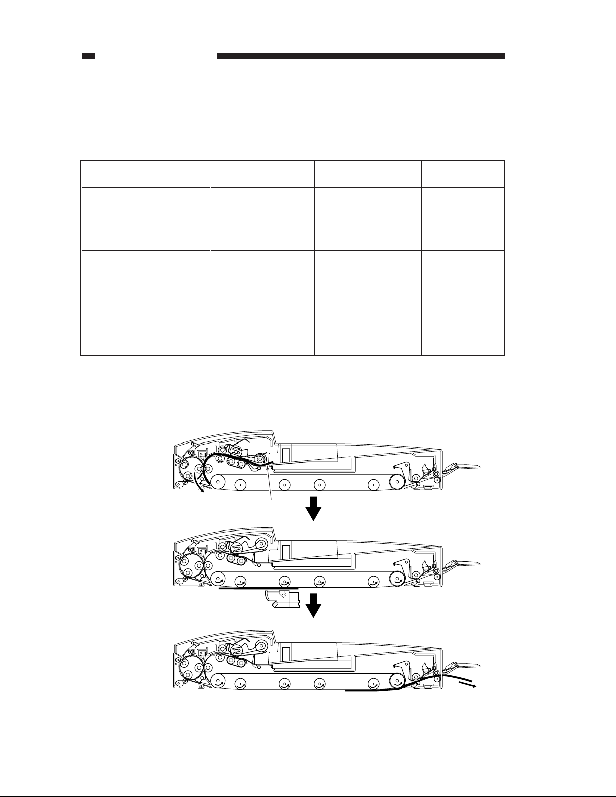
2. CWW Pickup/Delivery
An original moves as follows:
Outline
Picks up an original,
and delivers it as it is
after copying.
Reverses and picks up
an original, and
reverses once again
and delivers after
copying.
Picks up an original from
the pickup assembly, and
delivers it after copying.
Table 2-202
Corresponding
copying mode
Single-sided original
à single-sided copy
Single-sided original
à double-sided copy
Double-sided original à
double-sided copy
Double-sided original à
single-sided copy
Manual copying
Copying
operation
Stream reading
(fixed reading if
ratio is not
between 50% and
150%)
Fixed reading
Fixed reading
2-8
Pickup
Original
Copying
Delivery
Figure 2-203
COPYRIGHT © 1999 CANON INC. CANON ADF FOR iR600 REV.0 JAN. 1999 PRINTED IN JAPAN (IMPRIME AU JAPON)
CHAPTER 2 OPERATIONS
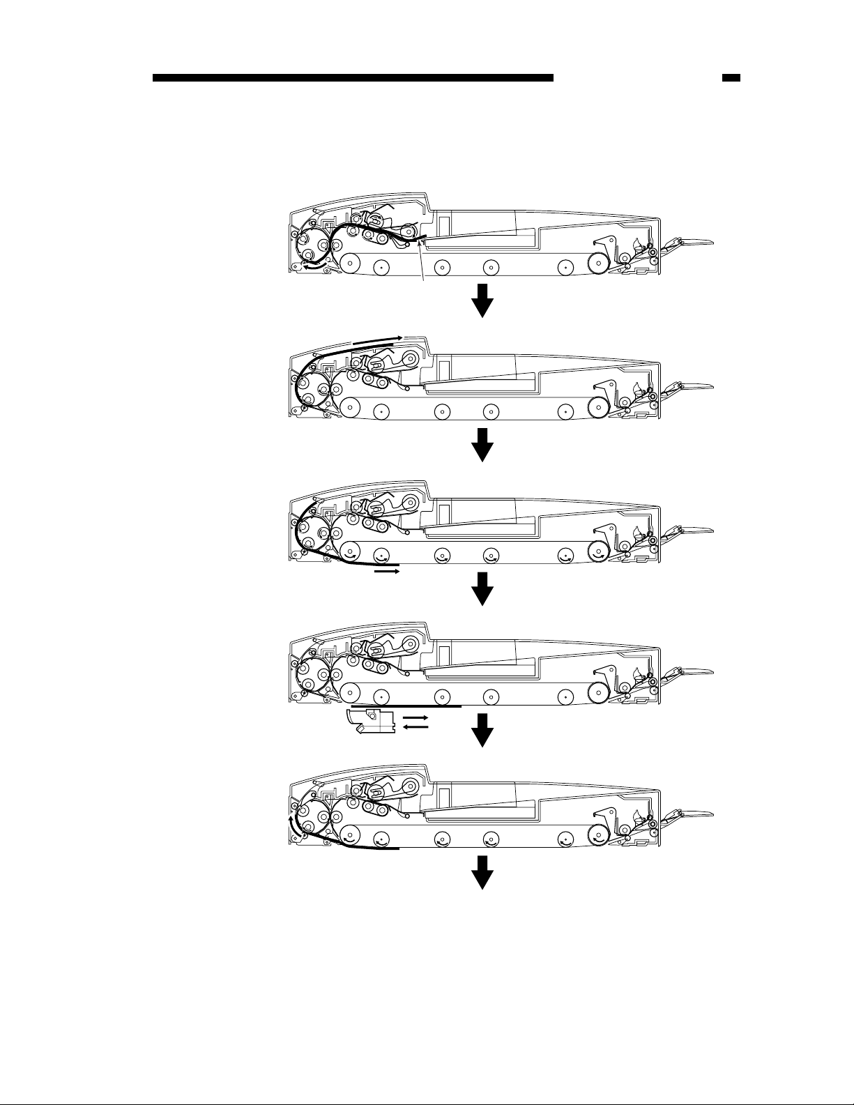
3. Pre-Reversal Pickup, Reversal, Delivery (small-size original)
An original moves as follows:
Pickup
Original
Pre-reversal
Feeding
Copying 1st side
Feeding
To next page.
Figure 2-204-1
COPYRIGHT © 1999 CANON INC. CANON ADF FOR iR600 REV.0 JAN. 1999 PRINTED IN JAPAN (IMPRIME AU JAPON)
2-9
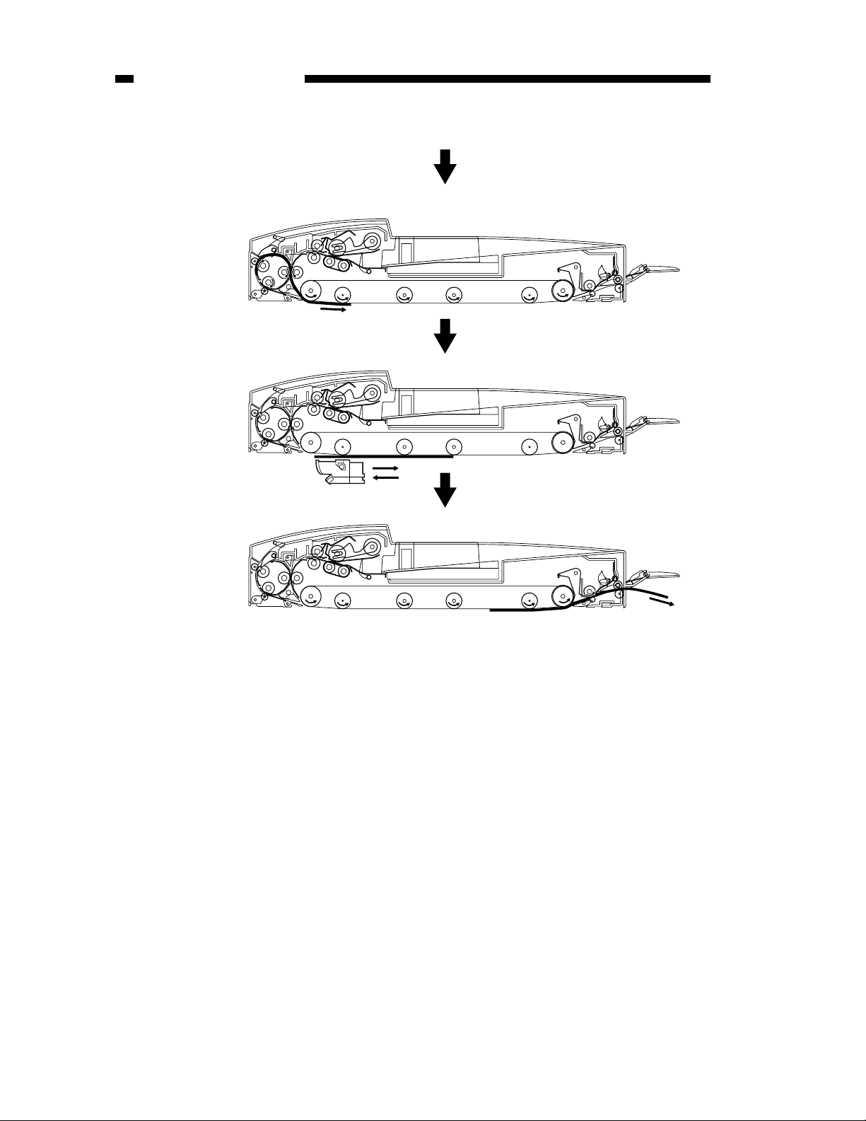
CHAPTER 2 OPERATIONS
Reversal
Copying 2nd side
From previous page.
Delivery
Figure 2-204-2
2-10
COPYRIGHT © 1999 CANON INC. CANON ADF FOR iR600 REV.0 JAN. 1999 PRINTED IN JAPAN (IMPRIME AU JAPON)
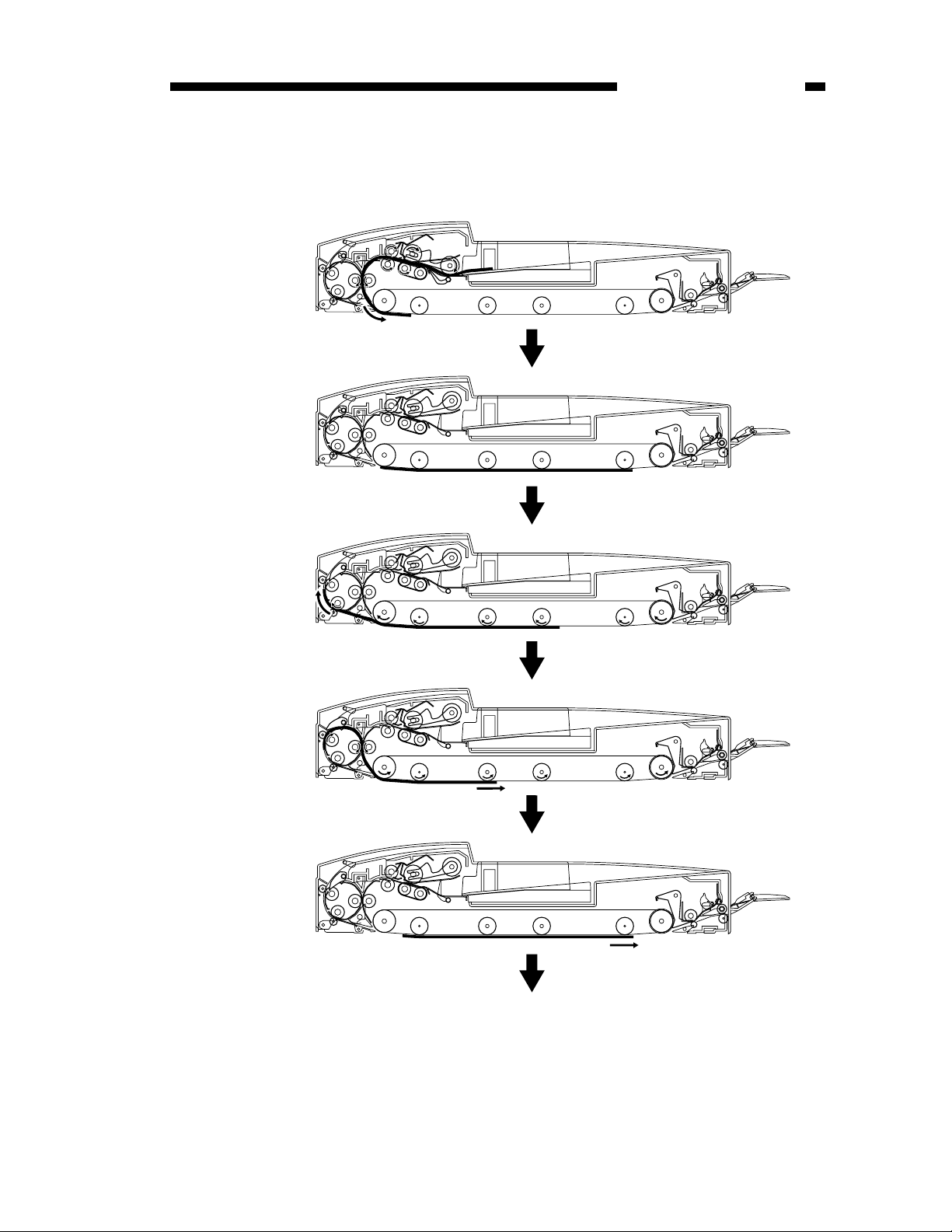
CHAPTER 2 OPERATIONS
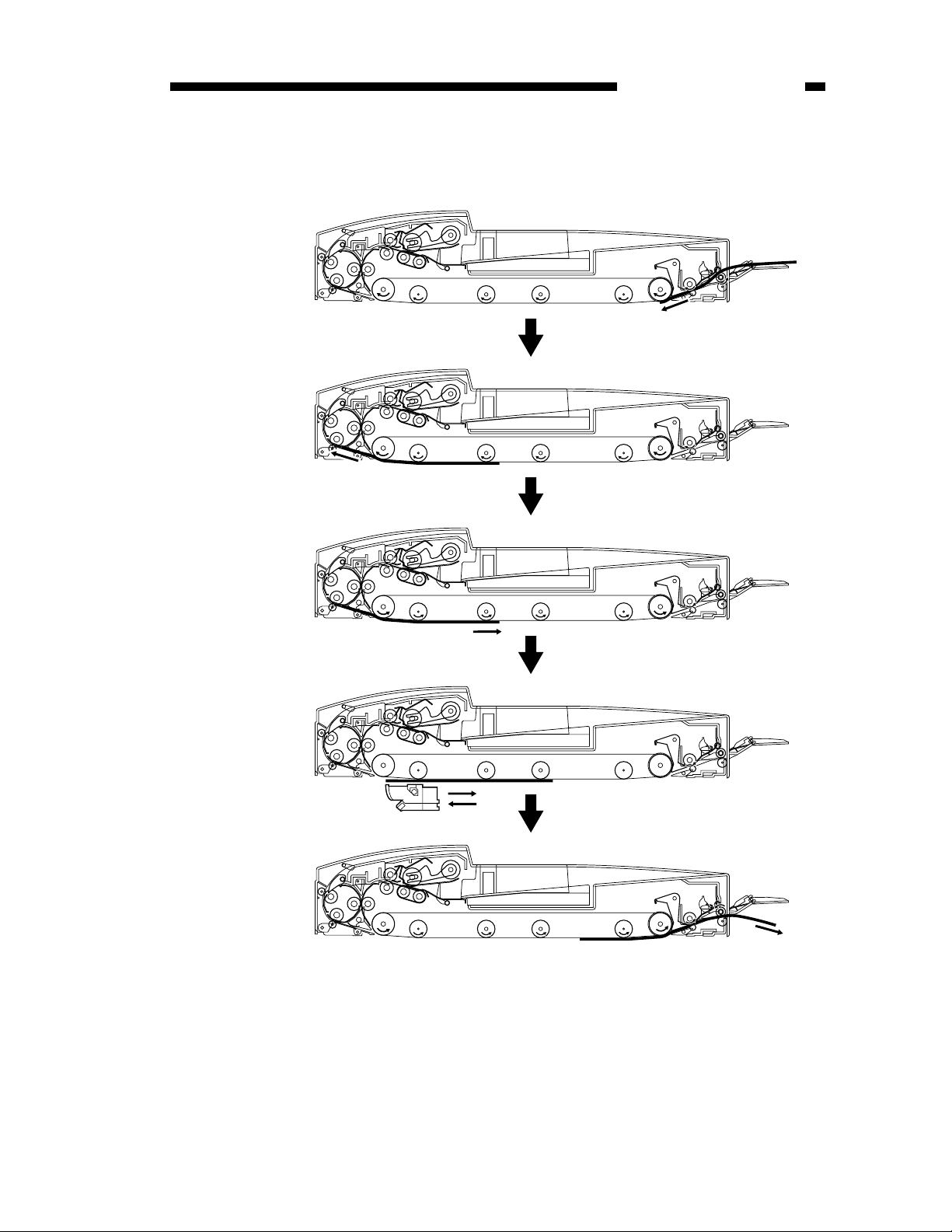
4. Reversal Pickup, Reversal, Delivery (large-size original)
An original moves as follows:
Pickup
Feeding
Reversal feeding 1
Reversal feeding 2
Copying 1st side
To next page.
Figure 2-205
COPYRIGHT © 1999 CANON INC. CANON ADF FOR iR600 REV.0 JAN. 1999 PRINTED IN JAPAN (IMPRIME AU JAPON)
2-11
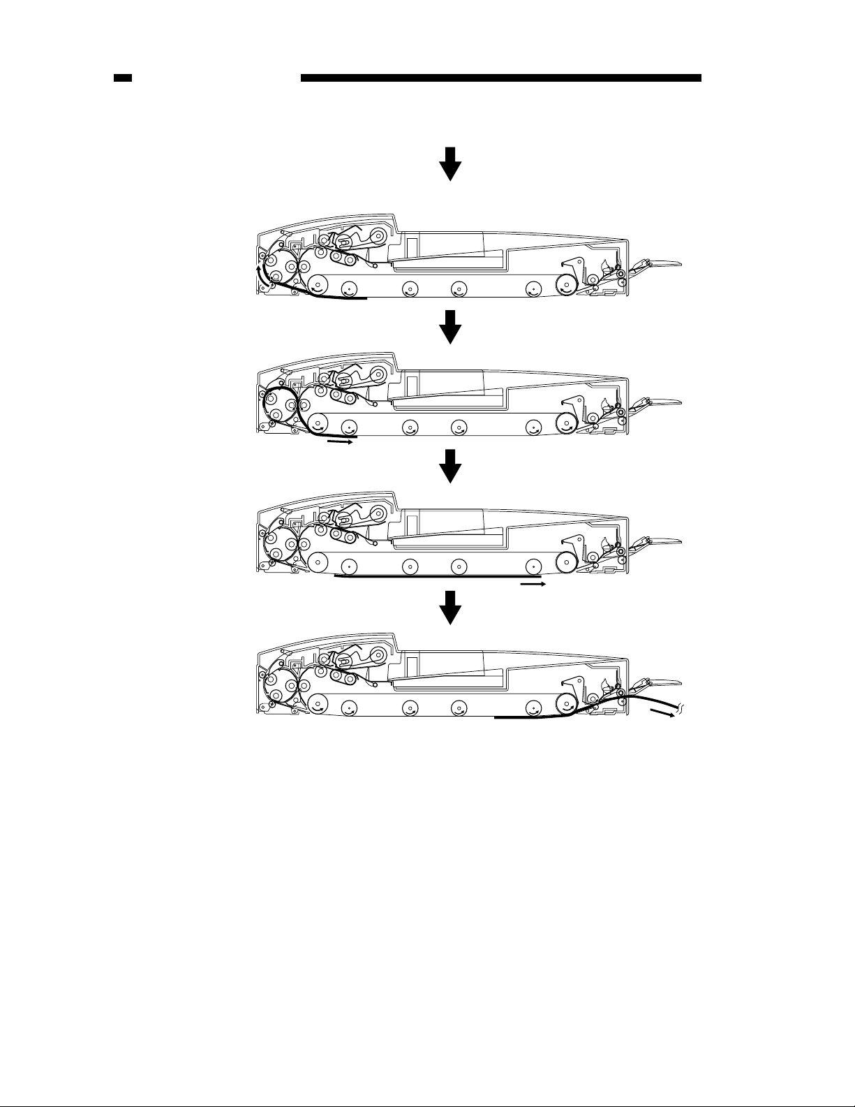
CHAPTER 2 OPERATIONS
Reversal feeding 1
Reversal feeding 2
From previous page.
Copying 2nd side
Delivery
Figure 2-206
2-12
COPYRIGHT © 1999 CANON INC. CANON ADF FOR iR600 REV.0 JAN. 1999 PRINTED IN JAPAN (IMPRIME AU JAPON)
5. Manual Feeder Pickup/Delivery
An original moves as follows:
Pickup
Stopping original
CHAPTER 2 OPERATIONS
Switch-back
Copying
Delivery
Figure 2-207
COPYRIGHT © 1999 CANON INC. CANON ADF FOR iR600 REV.0 JAN. 1999 PRINTED IN JAPAN (IMPRIME AU JAPON)
2-13
CHAPTER 2 OPERATIONS
C. Detecting an Original
1. Outline
The machine is equipped with the following five original detection mechanisms:
Function
Original detection
Original size detection 1
Original size detection 2
Pre-last original detection
Manual feeder original
detection
Description
Detects the presence/absence of an
original on the original tray.
Detects the size of an original set on the
original tray (large- or small-size).
Detects the size of an original being fed
(default size).
Detects whether the original on the
original tray is the last original or not.
Detects the presence/absence of an
original in the manual feeder.
Table 2-203
PI12
Sensor (notation)
Original sensor (S6)
Original trailing edge sensor
(S7)
Registration roller clock
sensor (PI5)
Original width detecting
switch (SW301)
Pre-last original sensor (S8)
Manual feed sensor (PI12)
2-14
S6
(light-emitting side)
S6
(light-receiving side)
S7
SW301
S8
PI5
Figure 2-208
COPYRIGHT © 1999 CANON INC. CANON ADF FOR iR600 REV.0 JAN. 1999 PRINTED IN JAPAN (IMPRIME AU JAPON)
 Loading...