

Page 1

Page 2

Electric Eye
Aperture Control
BiJ'IMn Lens Hood/F(
.VO \,
«andsfrap Fastener
Page 3

Latch
Eyecup
Page 4
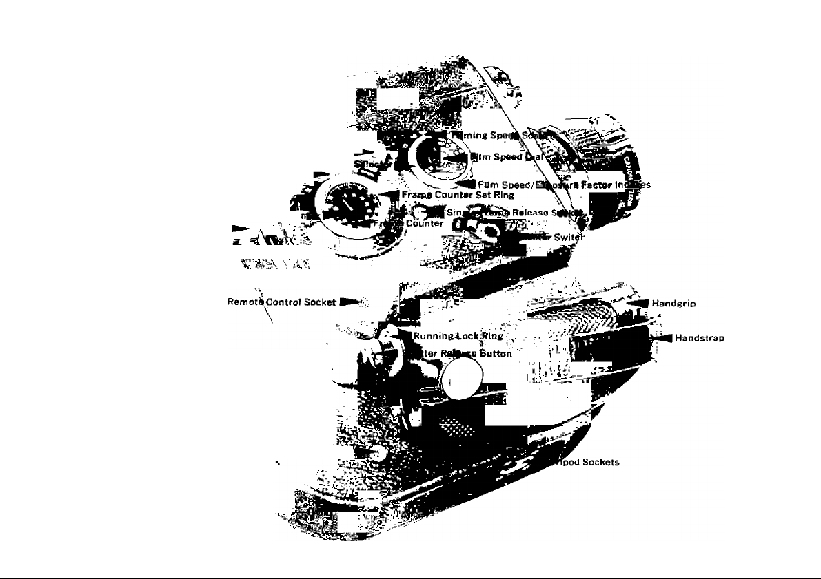
Battery Chamber Cover
Varrabte Shutter Control Lever
Knob for Battery Chamber Filmlr^g Speert:
Eyepiece Fixing IRng
Re\^indikg.S«fW^y^^
Eyepiece Adjiirtnier|t Ring
Eyepiece sht^ef^witc
Battery Check Button%fe'*i'/J^ie Battery Checker Window
Taflp|3la Shutter Scale
fajl^le
\\ * ’ Footage Cou
/
External Battery Box Socket
Tape Record^ Starting Socket
Si-
Page 5
Page 6

Procedures for Electric Eye Operation
■j Load and check the power level of the batteries. (Pages 7-8)
Adjust the eyepiece to your eyesight. (Page 8)
2
Set the master switch at “AUTO". (Page 9)
3
Load the Double Super 8 film. (Pages 22-24)
4
Set the film speed dial. (Page 9)
5
Set the filming speed at 18 fps. (Pages 9-10)
6
Set the variable shutter control lever at “OPEN". (Page 17)
Look through the viewfinder, focus at telephoto, and decide the
8
composition of the picture. (Pages 12-14)
Press the shutter release button slightly and check the position
9
of the exposure indicator. (Page 14)
start shooting by depressing the shutter release button all the
10
way down. Zoom in and zoom out according to your needs.
(Page 15)
Page 7
Page 8

When one side of the film (100 feet) has been fiimed, reverse
11
it and reioad for the remaining side. (Page 25)
1 O When both sides of the film have been exposed, unload it. and
turn the master switch to "OFF”. (Page 26)
page
Eyecup.................................................................................... 9
Variable Shutter Control..................................................... 16
Exposure Control by Variable Shutter.............................. 17
Fadings and Rewinding by Variable Shutter
Loading of Film
Reloading of Film ............................................................... 25
Unloading of Film ............................................................... 25
Filters and Adjusting of Film Speed
Manual Control of Aperture
Close-Up Lenses................................................................. 27
Remote Control
Using the External Battery Box
Tape Recorder Starting Socket
Cleaning the Aperture Section
Proper Care of the Camera
..................................................................
.................................
...............................................
..................................................................
........................................
........................................
.........................................
...............................................
...................
18
22
26
27
28
28
28
29
29
Page 9

Technical Data
Type: 8mm movie camera using Doubie Super 8 film (double width
film on 100-feet roll).
Frame Size: 4x5.4mm.
Lens: F 1.4 with focal length of 7.5-60mm. Zoom ratio 1 : 8. 13-
component, 18-element construction (including six rare earth
glasses). Inner diameter, 58mm. Outer diameter, 65mm.
Distance Scales: ft 50 15 10 7 5 4
Zooming : Manual, with zooming lever.
Viewfinder; Single-lens reflex type combined with built-in split-
image rangefinder. Contains exposure indicator, f/stops scale, over/
under exposure warning marks and manual aperture control mark.
Eyepiece is adjustable ( — 5 to +4 diopter). Magnification, 0.62x —
4.67x. With eyepiece shutter. Two types of eyecups are supplied
with the camera.
Electric Eye Mechanism : Automatic aperture setting coupled to
CdS photocell and servomotor. The Electric Eye is coupled to the
chan es in light volume received by the independent window. Light
receiving angle: approx. 20 degrees. Powered by the electric
motor used in common for film advance.
EE Working Range: Coupled to entire range of ASA 320, f/1.4,
12fps-ASA 10, f/22, 54 fps.
Manual Aperture Control: Possible by setting the master switch
at "MANU" and turning the aperture control ring.
Film Speeds: ASA 10-320, DIN 11-26.
Exposure Factor Compensation : 2x, 4x, 8x.
Filming Speeds : 12, 18, 24, 36, 54 fps and single frame release.
Running lock possible.
Variable Shutter Control: Consecutively from 0° to 165°.
“CLOSE”, “4”, “2” and “OPEN" with 0°, 41.25°, 82.5° and 165°
respectively. Exposure adjustment and fadings are possible.
OO
m 10 5 3 2 1.5 1.2
Page 10

Film Advance : Electric motor drive system. With shutter release
button.
Rewinding Mechanism : Electrically performed by setting the
variable shutter control lever at "R” and depressing the shutter
release button. Overlappings possible.
Power Source : Eight 1.5v penlight (size AA) alkaline or manganese
batteries. Use with exclusive battery magazine. Approx, nine reels
can be filmed with alkaline batteries under normal temperatures at
18 fps. External battery box using alkaline, manganese, or nickel
cadmium batteries adaptable.
Film Loading: Semiautomatically loaded by power in which the
film leader is inserted into the guide. Film cutter is built in.
Footage and Frame Counters : The footage counter has gradu
ations at 10-feet intervals. Rotates in forward and reverse directions.
Automatically resets when the side cover is opened. The frame
counter indicates 72 frames (one foot) with every one rotation.
Coupled to footage counter and able to count up to the single frame.
Various Sockets: For single frame, remote control, tape recorder
starting, and tripod.
Size : 268x227x103mm (10-1/2"x8-7/8"x4").
Weight: 3,370 grams (7 lb. 6-7/8 oz.).
Accessories: 65mm Lens Cap, 58mm Filters, Close-Up Lenses
(240, 450, and 1800), Remote Switch 3, Scoopic Battery Box, Bat
tery Magazine, Scoopic Battery Charger-S, Spool.
Subject to alterations.
Your Camera Body Number_
Date of Purchase__
__________
Dealer's Name
Page 11

We are highly gratified that you have selected the Canon
Zoom DS-8 — a wise choice that promises you many
delightful years of photographic experiences.
Canon is recognized the world over as the foremost
pioneer in the development of photographic equipment
of the highest quality and performance.
Whether your new DS-8 is for home use, news reportage,
laboratory, or for traveling, make the most of your oppor
tunities!
Page 12

Before Using...
Please read this instruction booklet carefully, and master the manipu
lations of the various parts completely before loading the film into
the camera. Once thoroughly versed in the correct handling of this
camera, you can use the Canon Zoom DS-8 to the fullest extent of
Its capabilities.
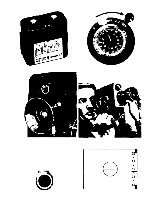
Loading of Batteries
Eight 1.5v penlight alkaline batteries (size AA) are used as the power
source for film drive and Electric Eye.
New batteries will provide power for driving approximately nine reels
of 100-foot length film at 18 fps under normal temperatures.
1 Remove the battery chamber cover by turning its knob counter-
I clockwise.
O Take out the battery magazine from the chamber and remove
^ the cover of the battery magazine by loosening the two knobs.
Insert the batteries in the correct direction according to the
3
diagram outside the magazine.
A Replace the cover of the battery magazine by matching its three
“ projections with the holes on the magazine properly and by
tightening the knobs.
Insert the battery magazine loaded with eight batteries by the
5
guide groove facing toward you.
Attach the cover of the battery chamber and turn its knob
6
clockwise.
■ Replace eight batteries simultaneously.
■ External Battery Box is recommended for outside power source
using manganese, alkaline, or nickel cadmium batteries.
Page 13

Page 14

■ Performance of the alkaline batteries deteriorates in temperatures
of 0°C (32°F) or under. Manganese batteries are recommended in
coid ciimates.
Checking the Power Level of the Batteries
The power level of the batteries can be checked by pressing the
battery check button and checking the position of the needle in the
battery checker window, if the needle reaches the blue zone, the
batteries have sufficient power level. If the needle is in the red zone,
the batteries must be replaced. If the needle is in between the two
zones, the batteries have a power level only for 24 fps or under.
■ Always check the power level of the batteries before shooting.
Adjusting Eyepiece
1 Remove the lens cap, set the eyepiece shutter switch at "0", and
I loosen the eyepiece fixing ring by turning it counter-clockwise.
O Aim the camera in the direction of a bright subject and look into
^ the viewfinder.
Turn the eyepiece adjustment ring and adjust it so that the
3
round edge of the rangefinder and f/stop scale can be clearly
seen. Then tighten the eyepiece fixing ring.
Page 15
Film Speed Dial
Film Spaed Index
Page 16

Eyecup
Two types of rubber-hooded eyecups are supplied with your camera.
One is for use by those wearing glasses and the other for those not
wearing glasses. Attach the eyecup of your preference.
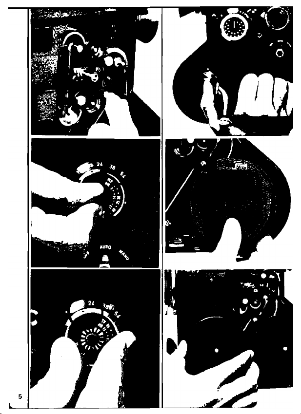
Master Switch
When the master switch is set at "OFF”, the Electric Eye circuit
I
is disconnected and the shutter is iocked.
When the master switch is turned to "AUTO”, the Electric Eye and
2
power circuits are connected and shooting with automatic expo
sure control becomes possible. The Electric Eye will function only
when the shutter release button is depressed.
When the switch is turned to "MANU", shooting with manual
3
aperture control for special effects becomes possible. Refer to
page 27.
■ When not using the camera, keep the master switch at "OFF”.
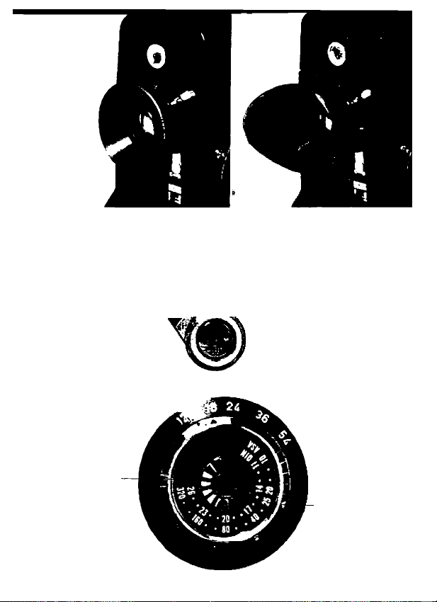
Setting the Film Speed
The Electric Eye of DS-8 is coupled to the film speed, filming speed
and aperture setting. Turn the film speed dial and set the ASA/DIN
speed of the film being used at the orange index "a" after loading
film so as to obtain the correct exposure.
■ Refer to page 17 and page 26 for the exposure factor indexes
(orange numerals).
■ The following film speeds may be used.
DIN 26 • • 23 • • 20 • • 17 • • 14 • • 11
ASA 320 • . 160 • • 80 • • 40 • 25 20 • • 10
Figures in parentheses represent intermediate film speeds.
(25) (24) (22) (21) (19) (18) (16) (15) (13) (12)
(250) (200) (125) (100) (64) (50) (32) (16) (12)
Page 17

Page 18

Selecting the Filming Speed
The filming speed selector sets the number of frames to be fed per
second. Turn the filming speed selector and set the index to the
desired filming speed graduation. 18 fps is the standard filming
speed for Super 8 cameras.
■ When shooting at 54 or 35 fps, the motor requires a sufficient power
level of the batteries.
■ Do not turn the filming speed selector while depressing the shut
ter release button.
■ The camera will function properly only at the graduations on the
filming speed scale.
■ Avoid operating the camera at high filming speeds when film is
not loaded.
Filming Speeds and Projection Effects
Film shot at filming speeds other than the standard speed of 18
fps will have varying effects when projected.
1 When shooting at high filming speeds of 54 or 36 fps, the pro-
I jected pictures will have a slow-motion effect. For example,
when a film is shot at 36 fps and then projected at the standard 18
fps, the projecting time will be lengthened by two times, thereby
slowing down the speed of motion by one-half. High filming speed
is, thus, very effective when slowing down fast moving subjects or
when analyzing movements. Exposure time is also speeded up and
is, therefore, effective for eliminating blurring during panning. 24
fps is also used for shooting standard sound film.
Page 19

Page 20

O When shooting at the slow filming speed of 12 fps, the opposite
^ effect of high filming speed is obtained. In other words, by
dropping the filming speed the projected pictures will have a fastmotion effect. This method is used when stressing the movement
of a subject, when a realistic effect in the movement of a distant
subject is desired, or for humorous effects. The slow filming speed
is also used in order to widen the proper exposure range for over
coming under-exposure conditions, that is, when it is too dark for
shooting at 18 fps even at maximum aperture opening.
■ Avoid shooting subjects that show normal movements when using
the slow filming speed for controlling the exposure.
Page 21

Page 22

Holding the Camera
Firmly grasp the handgrip with the right hand. The shutter release
button is depressed with the right thumb. Focusing, zooming and
steadying of the camera are performed with the left hand. The
camera should be held steady especially when shooting in telephoto
or when zooming. The use of a tripod is recommeded in these cases.
■ Do not take your eye away from the eyecup during shooting. This
is because, if the eyepiece receives strong light, reverse incoming
light may cause fogging of the film.
Handstrap
Open the handstrap buckle and adjust the length of the
according to your hand.
Eyepiece Shutter
Shift the eyepiece shutter switch to “C” when taking your eye away
from the eyecup such as when fading, panning, titling or performing
remote control.
handstrap
Page 23

Page 24

Viewfinder
Since the viewfinder of DS-8 is of the single-lens reflex type, the
exact picture image to be filmed can be seen without any parallax.
This enables you to compose the scene within the maximum fieldof-view.
■ Be sure the eyepiece shutter switch is set at “O”,
Zooming
When you wish to zoom or want to compose the picture properly in
the viewfinder, turn the zoom lens by using the zooming lever. The
image seen through the viewfinder will change in magnification and
the field-of-view will also change. When zooming is performed during
shooting, any desired zooming effect can be reproduced on the film.
■ The viewfinder magnification is in life-size when the focal length
is at 12mm.
Page 25

14
Page 26

Focusing
The Canon Zoom DS-8 has a split-image rangefinder built into the
center of the viewfinder. Adjust the focusing ring until the upper
and lower halves of the subject within the center circle of the view
finder are aligned and seen cleariy. Since the aligned image can be
seen more accurately and easily, first focus at maximum telephoto
focal length and then return to the desired magnification for shoot
ing. The focal point does not change by zooming.
■ The distance between the focused subject and the film plane can
be checked through the distance scale by drawing out the built-in
lens hood.
Checking the Exposure Indicator
Aim the camera at the subject and check the position of the expo
sure indicator inside the viewfinder. When you slightly depress the
shutter release button by approximately 1mm, the Electric Eye starts
to operate and the exposure indicator indicates the proper f/stop.
■ The black dots in between indicate f/16, f/8, f/4 and f/2 respec
tively.
1 If the exposure indicator is pointing inside the range of the f/stop
I scale, you may depress the shutter release button all the way
down and the film will advance.
O If the exposure indicator is pointing to the upper red mark, it
^ means over-exposure, and so an ND (neutrai density) filter must
be attached or the variable shutter control must be adjusted to lower
the light intensity.
lf the exposure is pointing to the lower red mark, it means under
3
exposure, and so the lighting must be increased.
Page 27

Page 28

Shooting
Depress the shutter release button all the way down for filming.
■ If the shutter release button Is depressed lightly, the operating
sound of the Electric Eye can be heard but the film will not advance.
■ Always use a built-in lens hood by drawing it out especially in
counter-lighted situations.
■ Set the master switch at “OFF” when not in use so as to prevent
inadvertent film drive.
Running Lock
While depressing the shutter release button all the way down, turn
the running lock ring counter-clockwise. You can now release your
right thumb from the button and the camera will continue to run
until the ring is returned to its original position.
Single Frame Release
Single frame photography is performed by inserting the cable release
into the single frame release socket.
Attach the camera on the tripod and set the filming speed at “12”.
Decide the proper f/stop, shift the master switch to “MANU”, and
depress the cable release to expose one frame at a time. Single
frame photography is applied to shoot animation, faked pictures and
to record the growth of plants.
Panning
Panning is employed when shooting a scene from one position to
another by moving the camera around horizontally to make a con
tinuous shot over a wide area in one sequence.
■ Do not move the camera too rapidly in any direction, particulary
vertically. Use of a tripod is recommended.
■ Panning shots are usually started from subjects of less impor
tance and move on to the most important subject where it ends by
running the film longer on the last sequence. Move the camera at
a constant speed.
■ Prevent a subject from being blurred by limiting the opening angle
of the shutter leaves and using high filming speeds.
Page 29

The film stops for
exposure.
16
An advance of the
exposed frame
takes places.
Page 30

Variable Shutter Control
Variable Shutter and Filming Speed
The shutter of the 8mm movie camera is closely connected with the
fiim advance. The exposure is made from the rotation of the two
semicircuiar ieaves which have given angies. When the leaves are
rotating, exposure of one frame and film advance are coupled, mov
ing synchronously. In other words, when the open section of the
leaves is at the aperture section, the film stops for exposure. And
when the aperture section is blocked by the rotating leaves, an ad
vance of the exposed frame takes place. Hence, the exposure time
is determined by the open angle of these leaves and the rotating
speed, and are called variable shutter angle and filming‘speed
respectively.
Exposure Adjustment with the Variable Shutter
For a still camera, shutter and aperture are freely adjusted for the
exposure adjustment. However, in the case of an 8mm camera the
filming speed cannot be changed at will since the standard speed is
fixed. Because under normal conditions, the shooting and projec
tion of the film are done at the standard speed, change of speed
should be made only when you intend to have special effects such
as faked shots. In other words, the exposure adjustment of the
movie camera is not done by changing the shutter speed but by
adjusting the aperture.
Instead of relying only on the aperture, the variable shutter enables
the change of exposure to be made with the shutter. By changing
the degree of the open angle of the shutter, the exposure time is
reduced. Although the ordinary 8mm camera has a shutter open
ing angle fixed at around 160°, the angle of Canon Zoom DS-8 may
be changed to any of the four stages between 165° to 0°. It is
possible, therefore, to make exposure adjustments freely and
perform fade-ins and fade-outs.
Page 31

Page 32

Exposure Control by Variable Shutter
Variable Shutter Control Lever
By sliding the variable shutter control lever, the open angle of the
shutter leaves changes and the exposure volume can be adjusted at
four stages.
To change the position of the variable shutter control lever, slide
it upwards and shift to the desired position. Slide the lever down
wards so as to fix its position.
Each stage of the scale is at a position which halves the open angle
of the shutter. Thus, the open angle degree of each scale is as follows:
“OPEN” “2” "4“ “CLOSE"
165° 82.5° 41.25° 0°
(Completely opened) (Completely closed)
■ By sliding the lever to the “S” position, film advance will be locked
and the shutter will not function.
Variable Shutter Angle and Filming Speed
Changing the variable shutter control lever will relatively affect the
filming speed and exposure time (in seconds) as follows:
Scale
"OPEN" 165"
"2" 82.5“ 1/52
-4-
"CLOSE”
Film Speed Adjustment
When the position of the variable shutter control lever is changed,
film speed setting should be adjusted to compensate the exposure
factor.
Match the film speed with the proper exposure factor mark which
is the same as the open angle index being used. For example, when
the variable shutter control lever is set at “2“, and the speed of the
film being used is ASA 25, set the scale of “25“ at the orange index
“2”.
Open
Angle
41.25” 1/104
0“
12 fps
1/26 1/39
- -
18 fps
1/79
1/158
24 fps
1/52
1/104
1/208
-
36 fps 54 fps
1/79 1/118
1/158 1/236
1/316 1/472
-
-
Page 33

18
Page 34

Effectiveness of the Variable Shutter Control
The variable shutter control increases the effectiveness of shooting,
besides the exposure adjustment, since a fast exposure time may
be attained at the same filming speed.
1 Since a shutter speed of 1/158 sec. can be obtained, even with a
• 18 fps setting, it prevents a moving subject from appearing blur
red as well as blurring caused by moving the camera.
O High filming speed may be used to film a moving subject at slow
^ speed and to get a sharp picture.
Q When the incoming light is exceeded, the exposure volume can be
” adjusted by two steps.
Fadings and Rewinding by Variable Shutter
Since the variable shutter control lever adjusts shutter from fully
open to totally closed, fade-ins and fade-outs can be easily under
taken. Moreover, overlappings can also be performed by utilizing the
rewinding mechanism.
Fade-Out
By sliding upwards and shifting the variable shutter control lever
towards the "CLOSE” position, the shutter can be closed and the
picture gradually darkens and finally fades out.
■ By sliding the lever to "S” the film advance will be interrupted
and will prevent wasting of film.
Fade-In
By shooting the film while progressively returning the variable shut
ter control lever from the "CLOSE” position to the "OPEN” side,
the dark picture gradually becomes brighter.
■ The fading technique is used in movies when there is a change of
scene. Generally speaking, the fade-ins are used at the beginning
of a movie and the fade-outs at the end. The fading technique
may also be used to show the elapse of time or a sudden change
in scene, although it should not be used too frequently.
■ For a quickly changing scene, a fading of l-1.5sec. would be ade
quate, or about 2-3 sec. in the case of a slow moving scene.
Page 35

Page 36

Overlapping
Overlapping a scene by combining the fade-out and fade-in for a
smooth transition of scene is known as the "overlap”. This techni
que is rather difficult to master and should be performed carefully.
Perform the fade-out with the variable shutter control lever.
1
Rewind the film footage which has been faded out. See page 20
2
on rewinding.
Fade-in in the next scene over this section. In other words, double
3
expose. This procedure will first make the scene darker and then
progressively brighten the scene which follows.
■ Be sure to calculate accurately the time of fade-in and fade-out
and the number of frames affected. Good effects can be obtained
only when the timing is correct. It is also essential that the variable
shutter control lever be shifted evenly and smoothly.
■ As for the time of the overlap, a period of under five seconds is
considered as appropriate.
Page 37

20
Page 38

Film Rewinding Mechanism
Film rewinding is powered by motor. The footage of the rewound
film can be ascertained up to a single frame by the frame counter.
While pressing the rewinding safety button, slide and set the
1
variable shutter control lever at "R”.
n By depressing the shutter release button, the film starts wind^ ing in reverse with the shutter leaves being closed. The frame
counter also rotates in reverse.
Frame Counter
The frame counter is used when performing overlapping or single
frame photography. One rotation of the frame counter equals 72
frames (one foot), and its indicator couples to the advance or
reverse operation of film.
The frame scale is movable and can be set at “0" position at the
indicator by turning the frame counter set ring. Thus, match "0" of
the scale with the indicator first, and then perform fade-in. Read a
number of the frame and rewind the film to "O” as is. By fading
in, the overlap can be made precisely and completely.
Generally, the use of 72 frames or less is advisable in fading tech
niques.
Page 39

will not be advanced when shifted to right.)
21
Page 40

22
Page 41

Loading of Film
Double Super 8 film, double the width of Super 8 film, is used for
Canon Zoom DS-8 and exposed one side of the strip at a time.
When one side is exposed, the film should be turned over and reload
ed so that the other half of the strip may be exposed.
The film is loaded by the semiautomatic loading system and can be
easily performed once you know how. Load and reload film correctly,
since carelessness may cause racing or fogging of the film.
■ As the film is wound naked around the reel, always load film in
the shade. An extra length of leader is attached to the film for pro
tection against the entry of light, but direct sunlight or strong light
ing may cause fogging of the film if it is loosely wound.
Set the master switch at “AUTO” and the filming speed selector
I
at “18”.
O Raise the side cover lock, turn it counter-clockwise and remove
^ the side cover.
0 Place the film spool on the feeding spool shaft as indicated by
w the diagram inside the camera.
k Trim the tip of the film leader at a right angle, using the built-
• in film cutter. Cut the tip of the film leader in between the
perforations.
Page 42

W- ^
r\ ■
23
Page 43

Insert the tip of the film leader into the film insertion guide. Be
5
careful to keep the film tightly wound on the reel.
Be sure that the pressure plate is at its proper position. If the
6
pressure plate is parted from the aperture section, the film can
not be advanced. Also check to see that the sprocket Guide and the
pressure plate tightening screws are not loose to secure the positive
film advance.
Depress the shutter release button while pushing the film leader
7
lightly into the film insertion guide. The film guide will close
and the film will automatically proceed through the film guides and
the aperture section and come out from the bottom sprocket. Stop
depressing the shutter release button when 15 to 20cm of film
leader has passed through the last guide roller.
Have the take-up spool ready. Bend the tip of the film leader
8
towards the emulsion side and insert into the take-up spool as
indicated by the diagram inside the camera. Wind the film leader
tightly three or four times around the spool.
Place the take-up spool on the take-up spool shaft.
9
Page 44

24
Page 45

in Depress the shutter release button, while pressing the film
* ^ guide reiease pin (the fiim guide is in open condition), and check
to see that the top and bottom film loops are uniform. Three to four
centimeters of film feed is sufficient.
11 Put the side cover back on, turn the film side cover iatch and
‘ ‘ flip it down.
1 O Depress the shutter reiease button and feed the film until the
footage counter moves from to "0”. Start shooting from
“0” position.
■ The fiim guides open when the fiim guide reiease pin is pressed
and cióse when the shutter reiease button is depressed. It is con
venient for correcting an improperly loaded film.
Footage Counter
As shooting proceeds, the footage counter indicates the iength of
exposed fiim in feet. The to "0” and' ‘100" to portions are
both lengths for leaders. The footage counter resets automatically
when the side cover is opened.
Page 46

25
Page 47

Reloading of Film
When one side of the strip has been completely exposed, reverse
and reload the film so as to use the remaining half.
When the footage counter indicates "100" for the first half of the
I
film, stop shooting.
Continue to depress the shutter release button until the in
2
dicator of the footage counter reaches
2 Open the side cover and remove both spools.
To use the remaining half of the film, reverse and interchange
4
the position of the two spools. The supply spool being inserted
into the shaft of the take-up spool and vice versa.
■ Be sure to reverse the spools when reloading. Otherwise, one
side of the film will be exposed twice.
Unloading of Film
After the footage counter reaches "100", continue feeding the film
until and then unload the film. Make certain that the film does
not loosen and put it into the film container. Send the exposed
film to an authorized processing laboratory.
Page 48

Type
o* uv
Y 1
о
Y 3
О 1
о
R 1
о
G 1
о
ND4
о*
ND8
SKYLIGHT
•
CCA 4
•
CCAS
•
CCA (12 equiv.)
•
CCB4
•
CCB (12 equiv.) 3
•
O For black and white film. # For color film.
26
Exposure
Factor
1
1.5
2
3
6
3
4
8
1
1.5
2
2
1.5
Filter Characteristics
Absorbs only ultra-violet rays. Especially ef
fective at seaside and high mountains. Re
commended for use in color photography.
Increases contrast of monochrome film.
Enhances clouds, darkening the blue sky.
Brightens red and yellow.
Darkens blue, increases yellow and red
perceptibly. Good for contrasts, especially
in distant landscapes.
Makes strong contrasts May also be used
with Infrared film,
Prevents red from turning radically into
white. Lightens faces and sky appropriately
and reflects the lightness of fresh greenery.
ND 4 reduces light volume by 1/4, ND8 by
1/8. No effects on the reproduction of col*
ors of color film.
Acts to harmonize the blue sky and shade.
For use with daylight type film under cloudy
condition.
For use with tungsten type film under the
morning sun or sunset.
For use with tungsten type film under sun
light.
For use with daylight type film In the morn
ing sun or sunset.
For use with daylight type film under tung
sten light.
Page 49

Filters and Adjusting of Film Speed
Filters
Various types of filters (58mm screw-in type) for Canon Zoom DS-8
are available.
Film Speed Adjustment
When using filters on the taking lens and/or the variable shutter
control lever is shifted other than to the “OPEN” position, the film
speed settings should be adjusted.
Turn the film speed dial and match the ASA/DIN of the film being
used with the proper orange index according to the exposure factor
of the filter and the position of the variable shutter control lever.
For example, when the ND 4 filter is used, the ASA/DIN figure should
be set at the orange index of “4”. And when the ND 4 filter is used
and the variable shutter control lever is set at “2“, the ASA/DIN
figure should be set at the orange index of “8’’ (i.e., 4x2 = 8).
■ Be sure to readjust the setting whenever detaching or replacing
a filter with a different exposure factor.
■ The exposure factors with respective filming speeds do not couple
to the following ASA/DIN film speeds. If the film speed dial is forci
bly turned the filming speed selector will move and settings cannot
be properly made.
Exposure Factor
Index
z
4
8
12fps
- -
-
ASA 10-16
D.N 11-13
ASA 10-20
DIN 11-14
Filming Speeds
ISfps 24fps 36fps 54fps
ASA 10
DIN 11
-
ASA 10-12
D.N 11-12
ASA 10-25
D»N 11-15
ASA 10
DIN 11
ASA 10 20
DIN 11-14
ASA 10-40
D.N 11-17
ASA 10-16
DiN 11-13
ASA 10-32
DiN 11-16
ASA 10-64
DIN 11-19
Page 50

Type
Focal Length
Distance Scale
Distance from Film
Plane to Subject
Picture Area
Type
Focal Length
Distance Scale
Distance from Film
Plane to Subject
Picture Area
27
58mm Close-Up Lens 450
7.5mm
1.2m (4')
609mm
(20
339x251mm 224x 166mm 45x33mm 30x22mm
(iai%^x9OT (8K"x6X0 dX^xl^sO (l^'^xKO
«. 1.2m (4')
394mm 353mm
179x 132mm 138x102mm
(7)i^'x5K0
475 mm
(1'6K0
58mm Close-Up Lens 240
7.5mm
a'3!iO ü'ií-h'o
60mm
609mm
(20
60mm
DO
394mm
(T30O
24 x 17mm
(%" X %0
1.2m (4')
475mm
1.2m (40
353mm
a'1^0
18 x 13mm
(K"xKO
Page 51

Manual Control of Aperture
Manual aperture control is used when shooting against the light or
when you wish to stress high-key or low-key effects. Zooming and
focusing are performed in the same manner as in Electric Eye
operation.
1 Set the master switch at "MANU". The letter "M" will appear
* in the upper part of the viewfinder.
O Turn the aperture control ring and set the exposure indicator
^ of the viewfinder to the desired f/stop.
■ The aperture control ring moves only when the master switch is
set at “MANU".
Close-Up Lenses
58mm Close-Up Lenses 450 and 240 are used when titling, copying
documents and when photographing plants and insects. 450 and
240 indicate the distance in millimeter from the tip of the lens to
the subject when the distance scale of the close-up lenses are set
at infinity.
■ When using a close-up lens the depth-of-field becomes shallow.
Therefore, close the aperture down to smaller than f/8.
■ Do not use a close-up lens at high magnification (telephoto),
unless for special effects, because the depth-of-field becomes shal
lower.
■ When the focal length is set at 60mm, you can obtain the same
effect as that of attaching a close-up lens at a shooting distance of
1.2m (4 ft).
Page 52

28
Page 53

Remote Control
With the use of the separately available Remote Switch 3, you can
operate the camera from a distance of 8 meters (26 feet).
1 Insert the remote control switch cord into the remote control
' switch socket of the camera.
O Turn the running lock ring counter-clockwise while depressing the
^ shutter release button.
0 Push the knob on the remote control switch in the direction of the
arrow. The camera will start to run until the knob on the remote
control switch is returned to its former position.
■ When disconnecting the cord of the remote control switch from
the camera, be sure to first return the running lock ring to its origi
nal position. Otherwise, the film will start advancing.
■ When shooting with the remote control switch, first ascertain the
position of the subject and then close the eyepiece shutter to
prevent reverse incoming light.
Using the External Battery Box
When the separately available Scoopic Battery Box is used, approxi
mately three reels can be shot at normal temperatures. This Battery
Box is composed of two 12v nickel cadmium batteries in parallel.
1 Remove the batteries loaded in the camera when using the
* Battery Box.
O Plug the cord of the Battery Box into the external battery box
^ socket.
■ Charge the batteries with Scoopic Battery Charger-S.
Tape Recorder Starting Socket
The tape recorder starting socket is coupled to the shutter release
button. If the remote control cord of a portable battery-powered
tape recorder is connected to this socket, the tape recorder starts
recording simultaneously with the shooting of the camera for record
ing the sounds of the surroundings to add more realism to the
movie. Acceptable power of the tape recorder; 24v 0.3A max.
Page 54

ì
29
ì
Page 55

Cleaning the Aperture Section
The aperture section, the section where the fiim is held by the pres
sure plate, should always be kept clean. It is best to clean this
section with a blower or a soft brush whenever new film is loaded.
Do not use anything hard, such as a metal brush.
The pressure plate can be removed by unscrewing its tightening
screw.
■ When loading film, check to see that the sprocket guide and pres
sure plate tightening screws are not loose to secure the positive film
abvance.
Proper Care of the Camera
1 Do not put fingerprints or other stains on the lens. Wipe
‘ gently with silicon cloth when removing stains and use a blower
for removing dust.
When using the camera on a rainy day or at the beach, moisture
2
and salt air adhere to it, which can result in stains, rust, and
corrosion. Remove them with a soft dry cloth as soon as possible.
ln hot climates, do not leave the camera insideclosedautomobiles
3
duringthe daytime or in direct sunlight.
In extremely cold areas, expose the camera gradually to the
4
outer air to prevent the lens from clouding. Since the perform
ance of the batteries drops at temperatures of 0°C (32°F), keep them
warm with your body temperature until just before use.
Before putting the camera into its case, be sure to turn the
5
master switch to "OFF".
When the camera is not to be used for a prolonged period of time,
6
remove the penlight batteries. Do not keep naphthalene or cam
phor near the camera.
"1 Periodic checks, cleaning and overhaul will prolong the life of the
• camera.
Page 56

-^••* . • »*
' - '“:i^
■—' -*T-'>^'’*-^** -<r*- ^ ■'“^ —•'‘■•✓ -w'* ^ '•'■ “■'•. ^"*‘ *“ >V"^-‘*'-^- •'f-,
•' • -. .•^^—W^-^» . - . - ,-r ■ . - ’ -, '.■ ^■ r- ^
"ÌM' *■ .. .’'^' -^ --.%> ^’* <^.—. •__‘ *•" . ,-r —'*•* -* -• •-—■ -* 1*“" ■.* '*-^
-• ■ W ^ -r-r:«' » r> J’ ^--*^
Cijn - ti,H
CANON INC.
9*9, Ginza 5-chome. Chuo ku. Tokyo 104, Japan
CANON U.S.A., INC.
64-10 Queens Bivd., Woodside, New York 11377, U.S.A.
CANON U.S.A., INC., CHICAGO OFFICE
457 Fullerton Avenue. Elmhurst, Chicago, Illinois 60126, U.S.A.
CANON OPTICS & BUSINESS MACHINES CO.. INC.
3113 Wllshire Blvd, Los Angeles, California 90005, U.S.A.
CANON AMSTERDAM N.V.
Gebouw 70, Schiphol Cost. Holland
CANON LATIN AMERICA, INC.
Apartado 7022, Panama 5, R.anama
PUB. K2070.B394B
PRINTED IN JAPAN
 Loading...