

Page 1
AUTOMAZIONE PER CHIUSURA INDUSTRIALE
CONTROL BOARD FOR AUTOMATIONS 24 V
SERIES Z
INSTALLATION MANUAL
ZL80 - ZL80C
Page 2
“IMPORTANT SAFETY INSTRUCTIONS WHEN INSTALLING”
WARNING: IMPROPER INSTALLATION MAY LEAD TO SERIOUS DAMAGE, FOLLOW ALL INSTRUCTIONS WHEN INSTALLING”
“THIS MANUAL IS EXCLUSIVELY INTENDED FOR PROFESSIONAL INSTALLERS OR OTHER COMPETENT PERSONS”
1 Legend of symbols
This symbols stands for parts that must be read very carefully.
This symbols stands for parts that have to do with safety.
English
This symbols stands for what needs to be notified to the client.
2 Intended use and limitations of use
2.1 Intended use
The ZL80_ZL80C control boards(The ZL80C: featuring incorporated buttons and safety stop) have been specifically designed for C-BXE24 automation, to drive sectional, sliding and folding doors.
2.2 limitations of use
- Respect cable distances and diameters as shown in the table in chapter 5.4
- Set up the control board in areas that are free of accidental impacts.
- For theZL80C version positions the control board at a height of 1.5 m from the ground.
3 Reference standards
This product complies with the following standards: EN 12978, UNI EN 954-1, CEI EN 60335-1, UNI EN 12453.
4 Description
4.1 230V a.c. control board
24V d.c. powered control board for gear motors; 50÷60 Hz frequency.
Designed and manufactured entirely by CAME Cancelli Automatici S.p.A. Container fi tted with air recycling intake.
Guaranteed 24 months unless tampered with.
4.2 Technical specifications
Control board
Power: 230V - 50÷60 Hz
Maximum output: 360 W
Draw at rest: 55 mA
Maximum output of 24V accessories: 36 W
Protection level: IP54
Insulation class: II
Material: ABS
Operatine temperature
2
#
Tutti i dati e le informazioni quì contenute sono da ritenersi suscettibili di modifica in qualsiasi momento e a nostro giudizio
#
Page 3
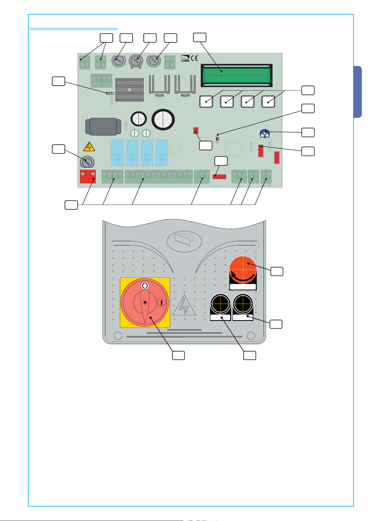
4.3 List of parts
ZL 80
CONTROL BOARD
ESC
ENTER
RSE
PROGRAMMING FUNCTION
R700
AF
LINE
FUSE
1,6 A
S1 GND
LN
+-
MN
L1T L2T 0 24
WARNING!
A
B
C
D
TERMICAL
PROTECTION
ACCESSORIES
FUSE 1,6 A
CONTROL BOARD
FUSE 1A
BATTERY
MOTOR
POT.ENC.
-
D
I
SPLA
Y
+
CON
TRAS
T.
MOTOR
FUSE 10A
#!-%
CONTROL BOARD
ZL 80
1
ZL80-ZL80C electronic board
PROGRAMMING FUNCTION
Emglish
12
CONTROL BOARD
FUSE 1A
MOTOR
FUSE 10A
ACCESSORIES
FUSE 1,6 A
432
TERMICAL
PROTECTION
9
13
ESC
><
ENTER
10
14
5
WARNING!
LINE
FUSE
1,6 A
%
P
#8 #9
19
6
8
RSE
%
'.$
!"
43
R700
AF
11
#!-%
1-Display
2- 1° Control unit fuses
3- 10 A motor fuses
1718
4- 1.6 A Accessories fuses
5- 1.6 A Line fuses
6-R700 board plug-in for decoding control devices (transponder slide-through cards)
7- AF board plug-in for radio frequency
8- RSE board plug-in for decoding PC interchange signal (for multiple control of to 16 units max.)
9-Led indicator: power
Tutti i dati e le informazioni quì contenute sono da ritenersi suscettibili di modifica in qualsiasi momento e a nostro giudizio
10-Led indicator: warns of open safety contacts error
11-Terminal board
12- Terminal board for connecting transformer
13-Programming buttons14-Trimmer to set display contrast
15- STOP button16- CLOSING button
17- OPENING button
18-safety stop
19- memory roll board connector ( backup device for system and user data)
ZTC5 pushbutton panel
15
16
3
Page 4
240
320
145
#!-%
240
320
165
#!-%
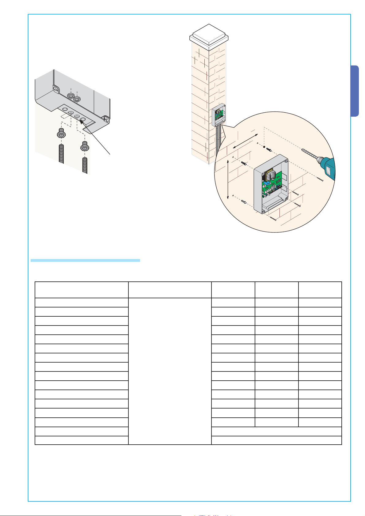
5 Installation
5 .1 Preliminary checks
Prior to installing the automation device do the following:
• Make sure that the control board is mounted in a sturdy manner and that it is protected from possible impacts. It must be
mounted using screws, anchor-plugs, etc. that are suitable for the type of surface;
• See to having a proper omnipolar disconnection device, with more than 3mm distances between contacts, and independent
English
(sectioned off) power;
• Make sure that any connections inside of the container (done for continuance of the protective circuit) be provided with
additional insulation as compared the other inside conducting parts;
• Install proper tubes and conduits to pull cables and wiring through making sure that these are protected from possible
mechanical damage.
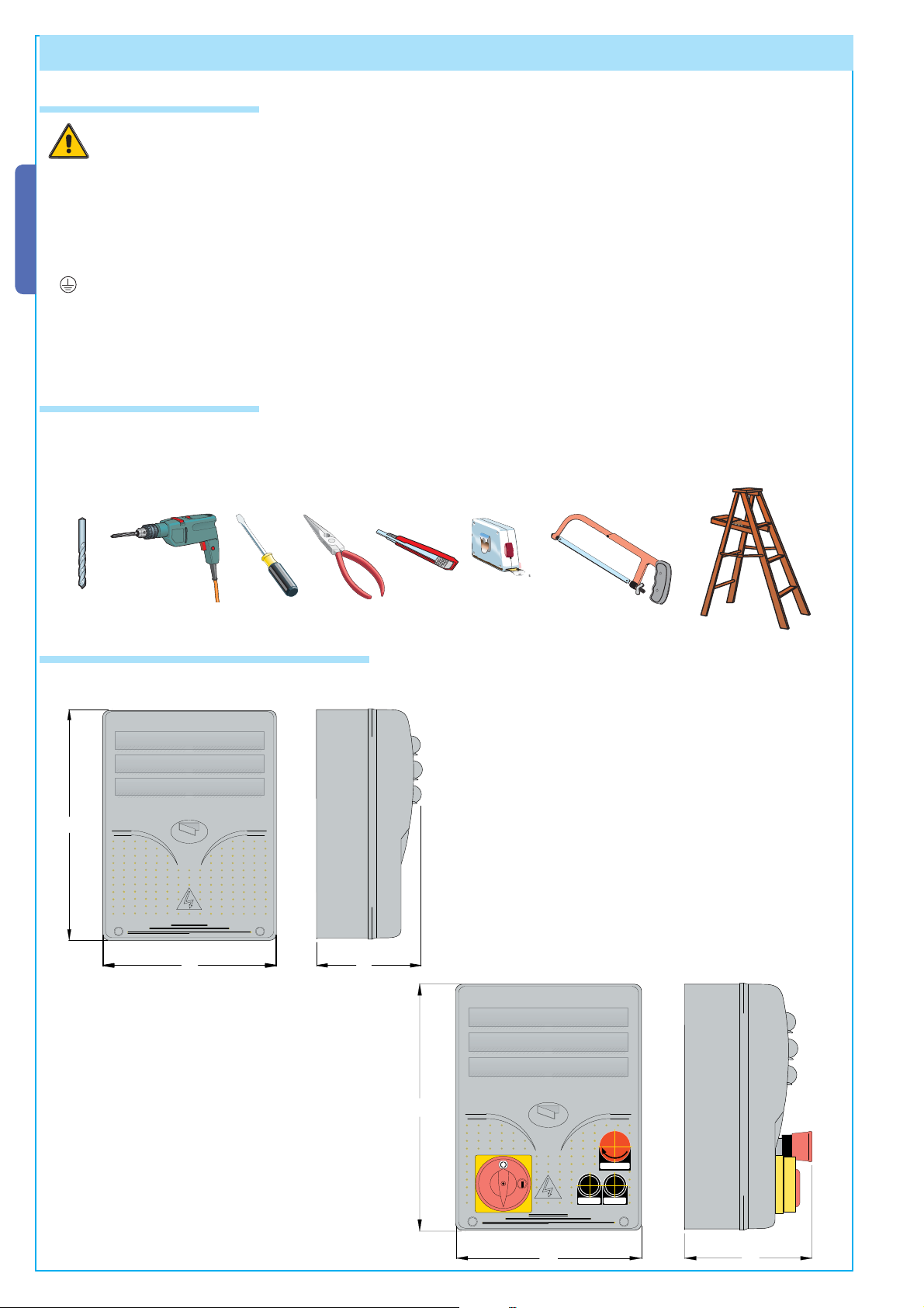
5.2 Tools and materials
Make sure to have all the tools and materials required to for installation under maximum safety conditions and in compliance
with current standards. The figure shows some of the equipment needed by the installer.
5.3 Dimensions, centre spacing and securing holes.
It is best to use 6 mm max diameter rounded-top cross-head screws .
Dimensions of the ZL80 container
320
#!-%
240
145
Dimensions of the ZL80C container
Tutti i dati e le informazioni quì contenute sono da ritenersi suscettibili di modifica in qualsiasi momento e a nostro giudizio
320
#!-%
240
!02%
#()5$%
165
4
Page 5
The pre-punched holes have
a 20/21 mm diameter
Emglish
215
295
5.4 Spessori minimi e tipo cavi
Connections Cable type
Power supply line, 230/400V 3F
Power supply line, 230V 2F 3G 1,5mm² 3G 2,5mm² 3G 4mm²
Motors, 230/400V 2F/3F 4G 1mm² 4G 1,5mm² 4G 2,5mm²
Motor, 24V 2 x 1mm² 2 x 1,5mm² 2 x 2,5mm²
Flashing lamp 230V 2 x 0,5mm² 2 x 1mm² 2 x 1,5mm²
Flashing lamp 24V 2 x 0,5mm² 2 x 1mm² 2 x 1,5mm²
Cycle/courtesy lights 230V 3G 0,5mm² 3G 1mm² 3G 1,5mm²
Power supply accessories 24V 2 x 0,5mm² 2 x 0,5mm² 2 x 1mm²
Warning light 24V 2 x 0,5mm² 2 x 0,5mm² 2 x 1mm²
Output 24V “in motion” 2 x 0,5mm² 2 x 0,5mm² 2 x 1mm²
Safety contacts 2 x 0,5mm² 2 x 0,5mm² 2 x 0,5mm²
Tutti i dati e le informazioni quì contenute sono da ritenersi suscettibili di modifica in qualsiasi momento e a nostro giudizio
N.O./N.C. control buttons 2 x 0,5mm² 2 x 0,5mm² 2 x 0,5mm²
End stop 3 x 0,5mm² 3 x 1mm² 3 x 1,5mm²
2nd motor control 1 x 0,5mm² 1 x 0,5mm² 1 x 1mm²
Antenna connection (max 50m) RG58
Encoder connection (max 30m) Insulated cable 2402C 22AWG
FROR CEI 20-22
CEI EN 50267-2-1
Cable length
1<10 M
4G 1,5mm² 4G 2,5mm² 4G 4mm²
Cable length
10<20 M
Cable length
20<30 M
PLEASE NOTE: If the cable length differs from that specifi ed in the table, then you must determine the cable diameter on the
basis of the actual power draw from the connected devices and depending on the standards specifi ed in CEI EN 60204-1.
For connections that require several, sequential loads on the same line, the sizes provided on the table must be reconsidered by
taking into account the actual distances and power draw. When connecting products that are not included in this manual then
follow the indications specifi ed in the documentation included with said products.
5
Page 6
LN
+-
MN
+
+ E
MN
MOTOR
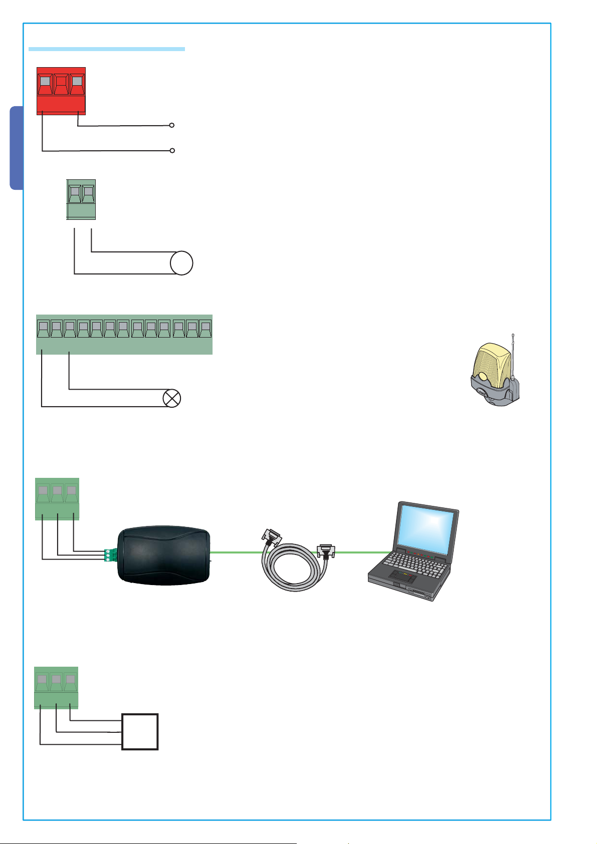
5.5 Electrical connections
English
230 V a.c. 50-60 Hz Power supply
24V D.C. Motor
M
AB
%
GND
P
#8 #9
43
24V a.c 25W Max. output terminal for flashing light (when moving)
Serial communication for PC connections: use mod. RS235 bipolar shielded cable with software (optional)
PC 40 o PC30
RS232 cable
Personal
Computer
-
+E
6
-
+E
E
E
-
-
+
Encode connection (to connect the automated device to the control board: use a type
2402C 22AWG shielded cable)
-
Tutti i dati e le informazioni quì contenute sono da ritenersi suscettibili di modifica in qualsiasi momento e a nostro giudizio
Page 7

5.5 Electrical connections
><
R700R700
AF
S1 GND
%
P
#8 #9
43
%
%
%
P
#8 #9
P
#8 #9
P
#8 #9
(1-2) N.C. STOP button
43
(2-3P) N.O. partial opening button
43
(2-3) N.O. complete opening button.
43
(2-4) N.O. closing button
Emglish
%
%
%
Tutti i dati e le informazioni quì contenute sono da ritenersi suscettibili di modifica in qualsiasi momento e a nostro giudizio
Antenna connection
TS
P
#8 #9
P
#8 #9
P
#8 #9
43
(2-7) N.O.open-close contact (in steps) or open-stop-close-stop (sequential)
43
(10-5) 24V 3W Max. opening indicator light
43
10-11 24V A.C accessories power supply output terminal, max 36 W
AF
7
Page 8

><
R700
AF
S1 GND
><
R700
AF
S1 GND
5.5 Electrical connections
English
Rx
10 2 TX C NC
10 11123p
Rx
10 2 TX C NC
DIR
3
457CX CY
DIR
Tx
(2-CX) DOC and DIR photocells connection
DOC
Rx
-
+
N.O.
C.
N.C.
Tx 2
TS
Tx
(2-CY) DOC and DIR photocells connection
10 11123p
3
457CX CY
Tx
+
-
TS
DOC
Tx
+
-
Tx 2
Rx
-
+
N.O.
C.
N.C.
10 11123p
Rx
10 2 TX C NC
10 11123p
3
457CX CY
DIR
3
457CX CY
TS
Tx
TEST DOC and DIR photocells working
10 11123p
3
457CX CY
TS
DOC
Rx
-
+
N.O.
C.
N.C.
Tx 2
TS
10 11123p
3
457CX CY
Tx
+
-
TS
(S1-GND) TSP00 (transponder) LT001 (slide-through card) sensor connection
Please note: for the board to recognise the sensors, the apposite (R700) decoder board needs to be connected.
TS
R700
LT001
R700
AF
CANCELLIAUTOMATICI
R700
CANCELLIAUTOMATICI
R700
ACCESSCONTROL
Tutti i dati e le informazioni quì contenute sono da ritenersi suscettibili di modifica in qualsiasi momento e a nostro giudizio
8
Red
Blak
TSP00
C
AME
TS
AF
Blak
Red
Page 9

ENTER
ENTER
ESC ENTER
><
PROGRAMMING FUNCTION
ENTER
ENTER
6 Programming
PROGRAMMING FUNCTION
PROGRAMMING FUNCTION
ESC
ENTER
>
<
PROGRAMMING FUNCTION
ENTER
ESC ENTER
><
PROGRAMMING FUNCTION
PROGRAMMING FUNCTION
PROGRAMMING FUNCTION
PROGRAMMING FUNCTION
PROGRAMMING FUNCTION
PROGRAMMING FUNCTION
PROGRAMMING FUNCTION
6.1 Description of display commands
PROGRAMMING FUNCTION
ENTER
the ENTER key is used to:
- access the menus
- confirm and memorise the set value
Emglish
WWW.CAME.IT
<>
ESC
LANGUAGE
CBXE 24
<
6.2 Browsing the menus
To enter a menu, keep the
ENTER key pressed for at least one
ENTER
second.
><
>
To select a menu
item, move with the
smaller than/greater
than keys…
ENTER
The ESC key is used to:
- exit the menus
ESC
<
...........
<>
<>
- cancel changes
the <> key are used to:
- move from one menu item to another
- increase or decrease any value
><
the <…..> symbols on the display indicate:
>
- the currently selected item
LANGUAGE
LANGUAGE
<>
TIMING
ENTER
><
EXAMPLE
Auto Clo.Time
<>
Tutti i dati e le informazioni quì contenute sono da ritenersi suscettibili di modifica in qualsiasi momento e a nostro giudizio
20 sec
Auto Clo. Time
<>
45 sec
Also for the “sub menus” move with the
smaller than/greater
than keys…
When the smaller than/
greater than <> symbols are on the TIME
function, its values may
be changed.
ENTER
…then press ENTER to
confirm…
…then press ENTER
Operation Time
<>
12 sec
Auto Clo.Time
<>
20 sec
To increase or reduce
the value use the smaller
than/greater than keys
><
…to exit the menu, wait 30
seconds, or press ESC, until
the initial screen reappears
ENTER
…then press ENTER
ESC
Please note: when the menu is active the system cannot be used.
9
Page 10

>
>
>
><
><
< >
< >
>
>
>
>
>
>
< >
< >
>
>
>
>
>
>
>
< >
< >
< >
< >
< >
>
>
>
< >
< >
>
>
><
><
>
>
>
< >
< >
< >
>
>
>
>
>
< >
< >
< >
< >
< >
< >
< >
< >
< >
< >
< >
< >
>
>
>
>
>
>
>
>
< >
< >
< >
>
< >
< >
>
>
>
6.3 Menu structure
ENTER
Press ENTER for 1 second
English
LANGUAGE
TIMES
FUNCTIONS
RADIO/
USERS
CALIBR.
INFO
ENTER
ENTER
ENTER
New user
Change user
Dele te user
Save memory
Load memory
Cancella tutti
ENTER
Run calibrat.
Obstr.sensitive
Partial ap. run
Network ID
ENTER
Version
No. manoeuv.
Startu p mess.
Operat. tim e
A.C.T.
ENTER
Flashing ti m e
A.P.C. tim e
Courtesy ti m e
ENTER
Radio funct.
Part. opening
ENTER
n.5 empty
ENTER
n.5 empty
ENTER
ENTER
ENTER
ENTER
ENTER
(Read only)
(Read only)
ENTER
< 10 sec >
ENTER
n.4 exists
< >
< >
n.4 exists
< >
ENTER
Writin g ...
ENTER
Reading ...
con firm?
<Y>
Procedu ra....
< >
< >
<N>
< 15% >
< >
< 40% >
< >
1 <-> 16
Procedu ra....
ENTER
< >
ENTER
< 10 sec >
ENTER
ENTER
< >
< >
< >
< 10 sec >
< >
< 10 sec >
< >
< >
< 10 sec >
< >
Aut. clos u re
2-7 co ntrol
User function
W. flashing
Dead Man
Dead Man clo s .
C1 Entryway
CX Entryway
Total stop
Service test
Ex outlet
Detect obstacle
Closin g push
Open indicator
Lang. selec.
ENTER
Italian
Englis h
French
Dutch
Spanisch
German
ENTER
ENTER
ENTER
ENTER
ENTER
ENTER
ENTER
ENTER
Disact
ENTER
ENTER
Attivo su CX/CY
ENTER
ENTER
ENTER
ENTER
<ON >
Sequential
Step-by-step
2-7 control
<ON >
<ON >
C1
F.C 2
Enabled
OFF
<ON >
<ON >
Intermittente
Continua
< >
<OFF>
Opens only
< >
<OFF>
< >
<OFF>
<OFF>
<ON>
< >
Disabled
< >
Disabled
< >
Cycle
Movement
< >
<OFF>
< >
<OFF>
C2
F.C 3
F.C 4
< >
< >
< >
< >
< >
< >
< >
< >
Tutti i dati e le informazioni quì contenute sono da ritenersi suscettibili di modifica in qualsiasi momento e a nostro giudizio
10
Page 11

6.4 Description of menu items
>
>
>
>
< >
< >
>
< >
< >
< >
>
>
>
>
>
< >
< >
< >
>
< >
> >
Language
Select language: select the menu language among those available.
LANGUAGE
ENTER
Lang. select
ENTER
Italian
German
Englis h French
Spanisch
Dutch
Time intervals
Time of operation: operating time intervals of the gearmotor during the opening phase or closing phase (from 10” o 120”)
TIMES
T.C.A. : automatic closing time following an opening command (from 1” to 120”).
TIMES
Pre-flashing Time: operating interval of the pre-flashing (from 1” to 5”).
TIMES
ENTER
ENTER
ENTER
Oper. tim e
x 1
x 2
ENTER
< 10 sec >
T.C.A.
ENTER
Pre-flashing
ENTER
< >
< 10 sec >
< >
< 5 sec >
< >
Emglish
Pedestrian T.C.A.: automatic closing time following a pedestrian opening command (from 1” to 120”).
TEMPI
Courtesy interval: courtesy lamp interval (from 1” to 120”).
TIMES
ENTER
ENTER
Functions
x 3
T.C.A. Pedonale
x 3
Courtesy ti m e
ENTER
ENTER
< 10 sec >
< >
< 10 sec >
< >
Automatic Closing: activates or deactivates the automatic closing function
FUNCTIONS
ENTER
Automatic cl.
ENTER
<ON >
< >
<OFF>
2-7 command: sets the sequential or in-steps contact.
FUNCTIONS
Tutti i dati e le informazioni quì contenute sono da ritenersi suscettibili di modifica in qualsiasi momento e a nostro giudizio
ENTER
x 1
2-7 co m m and
ENTER
Sequential
Step-by-step
< >
User function: assigns to the user either the opening command or the 2-7 function.
FUNCTIONS
ENTER
x 2
User function
ENTER
2-7 comm and
Opens only
< >
Pre-flashing: activates or deactivates the pre-flashing function.
FUNCTIONS
ENTER
Pre-flashing
x 3
ENTER
<ON >
< >
<OFF>
11
Page 12

>
< >
>
< >
>
< >
>
>
>
>
>>
>
>
> >
>>
>
< >
>
> >
>
>
< >
>
< >
< >
>
6.4 Description of menu items
Person Present (Maintained Action): activates or deactivates the Maintained Action function.
FUNCTIONS
ENTER
x 4
Dead man
ENTER
<ON >
< >
<OFF>
Person Present Closing (Maintained Action Closing): activates or deactivates the Maintained Action Closing function.
FUNCTIONS
English
ENTER
x 5
Clos. dead man
ENTER
<ON >
< >
<OFF>
CY Input: input terminal for N.C. safety contacts.The following functions can be associated:
C1: Reopening during closing phase C2: Reclosing during opening phase C3: Partial stop
C4: Obstruction standby C6: Reopening during closing phase (for safety edge).
FUNCTIONS
ENTER
x6
CY inlet
ENTER
C1
Disabled
C2 C3
C6
C4
CX Input: input terminal for N.C. safety contacts.The following functions can be associated:
C1: Reopening during closing phase C2: Reclosing during opening phase C3: Partial stop
C4: Obstruction standby C6: Reopening during closing phase (for safety edge).
FUNCTIONS
ENTER
x7
CX inlet
ENTER
C1
Disabled
C2 C3
C6
C4
Complete Stop: activates or deactivates the complete stop.
FUNCTIONS
ENTER
x 8
Total stop
ENTER
<ON >
< >
<OFF>
Maintenance Test: checks the proper functioning of the safety and detection devices of the input terminal to which they are connected.
FUNCTIONS
ENTER
Service test
x 9
ENTER
<OFF >
Attivo su CX
Attivo su CYAttivo su CX/CY
Lamp output: Output terminal for connecting the 24V flashing light, may be set in two modes of operation: Cycle – the
flashing light operates until the automated device is completely closed. Motion – the flashing light operates only when the
automated device is in motion.
FUNCTIONS
ENTER
x 10
Lamp output
ENTER
Cycle
Movement
< >
Obstacle detector: when the gearmotor is still, it prevents any movement whatsoever if any obstacle is detected by the safety devices.
x 11
FUNCTIONS
ENTER
Obstacle detec.
ENTER
<ON >
< >
<OFF>
Tutti i dati e le informazioni quì contenute sono da ritenersi suscettibili di modifica in qualsiasi momento e a nostro giudizio
Closing Boost: additional boost to optimise closure (suitable when the ground is not level)
FUNCTIONS
ENTER
x 12
Closin g push
ENTER
<ON >
< >
<OFF>
Closing indicator light: to select the operating mode of the motion indicator light.
FUNCTIONS
ENTER
x 14
Open indicator
ENTER
Intermittente
Continua
< >
12
Page 13

6.4 Description of menu items
>
>
>
< >
>
>
>
>
< >
>
>
< >
>
< >
>
< >
Radio/Users
Before plugging in any decoding/coding board cut power off to the control board (see p. 15)
New User: Add new users
RADIO/USERS
ENTER
New user
Vedere descrizion e dettagliata
Edit User: to edit a user’s functions.
RADIO/USERS
ENTER
x 2
New user
Vedere descrizion e dettagliata
Delete user: to delete a user from the files. (e.g. user n. 4)
RADIO/USERS
ENTER
x 3
Remove user
ENTER
Save to memory: saves users to the memory roll
RADIO/USERS
ENTER
x 4
Save memory
ENTER
Load memory: loads the data saved in the memory roll.
RADIO/USERS
ENTER
x 5
Load memory
ENTER
Delete all: deletes all the users on file.
RADIO/USERS
ENTER
x 6
Dele te all
n.4 exists
n.5 empty
ENTER
Writin g ...
ENTER
Reading ...
< >
Emglish
ENTER
Confirm?
<Y>
< >
<N>
Calibrations
Travel Run calibration: adjusts the leaf’s travel run and the Opening/Closing direction. (see p. 14)
CALIBR.
ENTER
Sensitive Safety Strip obstacle detector (obstruction detection sensor): adjusts the gate’s sensitivity, when obstructions are detected during motion.
CALIBR.
ENTER
x 2
Partial opening travel run: adjusts the partial opening travel run.
CALIBR.
Web/Network Address: assigns a value of between 1 and 16 for purposes of software recognition.
Tutti i dati e le informazioni quì contenute sono da ritenersi suscettibili di modifica in qualsiasi momento e a nostro giudizio
ENTER
CALIBR.
ENTER
x3
x 4
New user
Vedere descrizion e dettagliata
Saf. rib sen.
ENTER
Partial ap. run
ENTER
Network ID
+oooo-
•
< >
< 40% >
< >
< >
ENTER
1 <-> 16
INFO
Version: Visualises the software version Number of cycles: visualises the number cycles made.
Welcome message: to set the welcome message on the display.
INFO
ENTER
Startu p message
Vedere descrizion e dettagliata
13
Page 14

ESC
ENTER
PROGRAMMING FUNCTION
>
<
ESC
ENTER
>
<
PROGRAMMING FUNCTION
ESC
ENTER
PROGRAMMING FUNCTION
ESC
ENTER
PROGRAMMING FUNCTION
>
<
ESC
ENTER
>
<
PROGRAMMING FUNCTION
ESC
ENTER
PROGRAMMING FUNCTION
>
<
ESC
ENTER
PROGRAMMING FUNCTION
>
<
ESC
ENTER
>
<
PROGRAMMING FUNCTION
ESC
ENTER
PROGRAMMING FUNCTION
>
<
6.5 Travel Run calibration
1
From the calibration menu, select
Calibrate Travel Run. Press ENTER to
confirm.
Run Calibrat.
<>
2
Perform a complete opening run
using (<>), until the complete opening
occurs.
English
ESC
4
Carry out a complete closing run
<
using (<>), until the leaf is completely
closed.
Do a full
closing Run
>
ENTER
ESC
5
Press ENTER to confirm.
Do a full
Opening Run.
><
ENTER
3
Press ENTER to confirm.
6
6 – Set the gate leaf in motion for
at least 3”
Set opening dir
<>:move ENT:OK
ESC
7
Press ENTER to confirm.
><
Direction store
Waiting...
ESC
10
Use the (<>) to fully open the
><
gate
Set opening pnt.
<>:move ENT:OK
ESC
><
ENTER
ENTER
ENTER
8
Use the (<>) to take the gate leaf
to its closing point
Set close Pnt
<>:move ENT:OK
ESC
11
Then press ENTER to confirm.
><
Set Up OK
Waiting...
ESC
<
>
ENTER
ENTER
ESC
9
Then press ENTER to confirm.
><
ENTER
Closure stored
Waiting...
ESC
12
If the calibration (a) has not been
<
>
ENTER
done properly or, (b) has not been
completed, one of the following warning messages will appear:
- (a) reprogram…thus start over from
point 1.:
- (b) reposition the encoder…proceed
with point 13.
Tutti i dati e le informazioni quì contenute sono da ritenersi suscettibili di modifica in qualsiasi momento e a nostro giudizio
13
– Move the wheel towards the
+ side or – side depending on what the
display requests.
Move 6 notches
in direction (+)
14
14
-Press ENTER to confirm and
start over form point 1
Adjustment ok
run calibration
Press Enter
to end
Page 15

6.6 Decoding board
ESC
ENTER
PROGRAMMING FUNCTION
>
<
ESC
ENTER
PROGRAMMING FUNCTION
ESC
ENTER
PROGRAMMING FUNCTION
ZL 80
CONTROL BOARD
ESC
ENTER
RSE
PROGRAMMING FUNCTION
R700
AF
LINE
FUSE
1,6 A
S1 GND
LN
+
-
MN
L1T L2T 0 24
WARN
I
NG
!
A
B
C
D
TERMICAL
PROTECTION
ACCESSORIES
FUSE 1,6 A
CONTROL BOARD
FUSE 1A
BATTERY
MOTOR
POT.ENC.
-
D
I
SP
L
A
Y
+
C
O
NT
R
A
ST
.
MOTOR
FUSE 10A
To control the board using remote controls or cards, connect the AF radio board chosen for the corresponding remote control,
and the R 700 board for the TSP00/LT001 proximity sensors.
Please note: users cannot be added without the proper decoding board (max. number of users is 250).
The AF and R700 boards must be inserted with the power source disconnected
WARN
TERMICAL
PROTECTION
MOTOR
CONTROL BOARD
FUSE 1A
ING!
LINE
FUSE
1,6 A
ACCESSORIES
FUSE 10A
%
FUSE 1,6 A
P
#8 #9
PROGRAMMING FUNCTION
CONTROL BOARD
ZL 80
ESC
'.$
!"
43
RSE
6.7 Adding users
1
From the Radio/Users menu, select New
User. Press ENTER to confirm
New User
<>
%
Emglish
R700
CANCELLIAUTOMATICI
><
ENTER
R700
AF
Frequency/MHz Board Trasmitter
FM 26.995 AF130 TFM
FM 30.900 AF150 TFM
AM 26.995 AF26 TOP
AM 30.900 AF30 TOP
AM 433.92 AF43S / AF43SM TAM / TOP
AM 433.92 AF43SR ATOMO
AM 40.685 AF40 TOUCH
2
Choose the function associated with the user
(User Function or Partial Opening). Press ENTER to
confirm…
Ass. function
User function
<>
3
remote control, a slide-through card or a transponder, depending on the type of sensors installed in the system at hand
Tutti i dati e le informazioni quì contenute sono da ritenersi suscettibili di modifica in qualsiasi momento e a nostro giudizio
4
code or not.
ESC
..a code will be required which may inserted with a
><
ENTER
Once the remote control or card code has been added,
the word Memorised will appear on the screen (if the
n. 1 Await. cod
.....
<>
In any case a window will appear asking whether we wish to add a new
Another code?
<>
NO
Another code?
<>
YES
ESC
><
ENTER
code has yet to be added), or the
word On file (if the code has already
been added).
ACCESSCONTRO L
n. 1 Await. cod
Saved!
n. 2 Await. cod
n. 1 exist
By selecting NO the user adding procedure will be terminated. By selecting YES
the procedure reopens at point 3.
ESC
><
ENTER
15
Page 16

ESC
ENTER
PROGRAMMING FUNCTION
ESC
ENTER
PROGRAMMING FUNCTION
ESC
ENTER
PROGRAMMING FUNCTION
>
<
ESC
ENTER
PROGRAMMING FUNCTION
>
<
ENTER
><
ENTER
ESC ENTER
><
PROGRAMMING FUNCTION
6.8 User changes (user fucntion)
1
From the Radio/Users menu, select
User Changes, press ENTER to confirme.
2
Select the user which requires a change in function (a) by using the <>
or (b), by pressing the relative transmitter button, and (c) pulling the card
through the sensor. Press ENTER to confirm.
Change users
<>
Change user
<>
n.1 exist
English
ESC
3
select the function requried for the user. Press ENTER to confirm.
P.N. pressing ENTER to confirm takes you back to the User Changes window.
Ass. function
User function
<>
><
ENTER
ESC
Ass. function
<>
Part. opening
ACCESSCONTRO L
><
ENTER
ESC
><
ENTER
>
ENTER
6.9 Changing the initial message
1
From the INFO menu, select Initial
Message. Press ENTER to confirm
ENTER
Startup mess.
<>
WWW.CAME.IT
ESC
2
Write the desired message: the maximum number of characters is 32 (16 per line). Once the message is written keep
><
ENTER
ESC
the ENTER key pressed for at least 3”
The Enter key servers to:
- Move the cursor to the right
- To confirm when it is kept pressed for more than 3”
The ESC key serves to:
- Move the cursor to the left
- To exit is it is kept pressed for more than 3”
The <> greater than/smaller than keys serve to:
- select the desired letter or the empty space.
><
Tutti i dati e le informazioni quì contenute sono da ritenersi suscettibili di modifica in qualsiasi momento e a nostro giudizio
16
WWW.CAME.IT
CBXE 24
Page 17

6.10 Error message
“STOP Contact Open”: Check proper connection or effi ciency of the device
“Service Check!!!” Malfunctions are present in the safety devices.
“Encoder Out of Order: check the proper connection or effi ciency of the device.
“CX-CY Contact Open”: check the proper connection or effi ciency of the device.
7 Mounting the container cover
Emglish
1
Assemble the pressare hinges
!!
2
Insert the hinges into the container (on the
15 mm~
right or the left as desired) and fix them using
the supplied nuts and screws.
they flow for rotating
Lock the cover
into hinges,
close it and fix
it using the supplied screws.
3
8 Product Disposal
I CAME products are made using several materials. For the most part they are (aluminium, plastic, iron, electrical cables)
and can be disposed of with solid urban waste. They may be recycled through differentiated waste collection and disposal
methods at authorised centres.
Other components (electrical boards, the batteries to the remote controls etc.,) may, however, contain polluting substances.
They must therefore be removed and turned over to specialised fi rms that are licensed to dispose of the same.
9 Statement of Confomity
MANUFACTURER’S DECLARATION
As per Enclosure II B of Machinery Directive 98/37/CE
Enclosed with the technical documentation (the original copy of the Declaration is available on request)
The representatives of
CAME Cancelli Automatici S.p.A.
via Martiri della Libertà, 15
Tutti i dati e le informazioni quì contenute sono da ritenersi suscettibili di modifica in qualsiasi momento e a nostro giudizio
31030Dosson di Casier - Treviso - ITALYtel
(+39) 0422 4940 - fax (+39) 0422 4941
internet: www.came.it - e-mail: info@came.it
Hereby declare, under their own respons ibility, that the product/s called ...
ZL80 - ZL80C
… comply with the Italian National Legal Provisions that transpose the
following Community Directives (where specifi cally applicable):
ACHINERY DIRECTIVE 98/37/CE
M
OW VOLTAGE DIRECTIVE 73/23/EEC - 93/68/EEC
L
ECTROMAGNETIC COMPATIBILITY DIRECTIVE 89/336/EEC - 92/31/EEC
L
IRECTIVE 1999/5/CE
R&TTE D
Also, they furthermore represent and warrant that the product/s that are the subject of the present
Declaration are manufactured in the respect of the following main harmonized provisions:
EN 292 PART 1 AND 2 MACHINERY SAFETY.
EN 12453 I
EN 12445 I
EN 12978 SAFETY DEVICES FOR POWER OPERATED DOORS AND GATES ....
EN 60335 - 1 SAFETY IN APPARATUSES FOR HOME USE.
EN 60204 - 1 MACHINERY SAFETY.
EN 61000 - 6 - 2 E
EN 61000 - 4 - 4 E
EN 61000 - 4 - 5 ELECTROMAGNETIC COMPATIBILITY.
IMPORTANT CAUTION!
It is forbidden to market/use product/s that are the subject of this declaration before completing and/or
incorporating them in total compliance with the provisions of Machinery Directive 98/37/CE
NDUSTRIAL, COMMERCIAL AND OTHER CLOSING MECHANISMS.
NDUSTRIAL, COMMERCIAL AND OTHER CLOSING MECHANISMS.
LECTROMAGNETIC COMPATIBILITY.
LECTROMAGNETIC COMPATIBILITY.
Signatures of the Representatives
TECHNICAL MANAGER
Mr. Gianni Michielan
Date of the present declaration 07/12/2001
MANAGING DIRECTOR
Mr. Paolo Menuzzo
17
Page 18

CAME UNITED KINGDOM LTD
UNIT 3, ORCHARD BUSINESS PARK
TOWN STREET, SANDIACRE
NOTTINGHAM - NG10 5BP - U.K.
Tel 0044 115 9210430
Fax 0044 115 9210431
Cod.ZL80_ZL80C319T98 V0.1-02/06© CAME CANCELLI AUTOMATICI
 Loading...