

Page 1
CANCELLI AUTOMATICI
SERIE Z |
QUADRO COMANDO
CONTROL PANEL
CUADRO DE MANDO
Z
SERIES
|
SERIE Z
ZL22
Documentazione
Tecnica
T13
rev. 0.4
11/2003
©
CAME
CANCELLI
AUTOMATICI
319T13
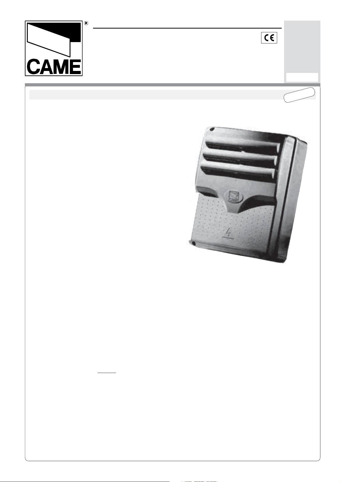
CARATTERISTICHE GENERALI
Descrizione quadro comando
Progettato e costruito interamente dalla
CAME Cancelli Automatici S.p.A., risponde
alle vigenti norme di sicurezza.
Quadro elettrico per
UNIPARK
in corrente continua 24V.
motoriduttori serie
Alimentato a 230V (a.c.) con frequenza 50/
60 Hz sui morsetti L1-L2, protetto in
ingresso con un fusibile di linea da 5A.
Contenitore in ABS completo di trasformatore, dotata di presa per il riciclo d'aria con
grado di protezione IP54.
Garantito 24 mesi salvo manomissioni.
I dispositivi di comando sono a bassa
tensione e protetti con fusibile da 315mA.
La potenza complessiva degli accessori a
24V protetti da un fusibile a 3.15A, non
deve superare i 60W.
Italiano
Logica di comando, sicurezza e
accessori collegabili
La centralina è dotata di:
- finecorsa di apertura e chiusura elettrici,
ottenuti con sistema amperometrico;
- trimmer che regola la sensibilità della
forza sviluppata del motore;
- predisposizione per l’inserimento del
ricevitore radio per comando a distanza;
- possibilità di comandare fino a 4 motori
(l’installazione di più motori si ottiene,
inserendo la scheda
LM22
per ogni
motore).
Page 2

GENERAL CHARACTERISTICS
English
Control panel description
Designed and built entirely by CAME
CANCELLI AUTOMATICI S.p.A., meets the
current safety standards.
Electric panel for
UNIPARK Series
gear
motors in 24V (DC).
Powered at 230V (AC) with frequency 5060 Hz on the terminals L1-L2, protected in
input with a 5A line fuse.
ABS container complete with transformer,
ITALIANO - ENGLISH - ESPAÑOL
equipped with socket for air recycling with
IP54 protection level.
Guaranteed for 24 months if not tampered
with.
The command devices are low voltage and
protected with a 315mA fuse. The overall
power of the 24V accessories protected by
a 3.15A fuse, must not exceed 60W.
Command logic, safety and
connectable accessories
- opening and closing electric end-stop,
obtained with amperometric system;
- trimmer that regulates sensitivity of the
force generated by the motor;
- pre-configured for inclusion of the radio
receiver for remote control;
- possibility of controlling up to 4 motors
(the installation of more motors is obtained
by installing the board
LM22
for each
motor).
The gearcase is equipped with:
CARACTERISTICAS GENERALES
Descripción del cuadro de mando
Diseñado y fabricado completamente por
CAME Cancelli Automatici S.p.A.,
responde a las normas de seguridad
vigentes.
Cuadro eléctrico para
serie UNIPARK
a corriente continua 24V.
motorreductores
Alimentado a 230V (a.c.) con frecuencia
50/60 Hz sobre bornes L1-L2, protegido
en entrada con un fusible de línea de 5A.
Caja de ABS con transformador, dotada
de toma para recirculación de aire con
clase de protección IP54.
Garantía 24 meses salvo alteraciones.
Los dispositivos de mando son de baja
tensión y están protegidos con fusible de
315mA. La potencia total de los
accesorios a 24V, protegidos por un
fusible de 3.15A, non debe superar 60W.
Lógica de mando y seguridad
Español
La central está equipada con:
- fines de carrera eléctricos de apertura y
cierre, obtenidos con sistema
amperimétrico;
- trimmer que regula la sensibilidad de la
fuerza desarrollada por el motor;
- adaptación para el montaje del
radiorreceptor para accionamiento a
distancia;
- posibilidad de accionar hasta 4 motores
(la instalación de varios motores se logra
conectando la tarjeta
LM22
para cada
motor).
-2-
Page 3
Italiano
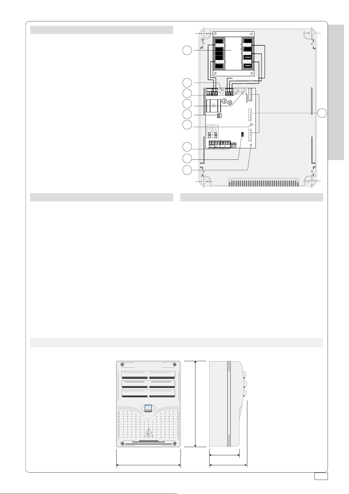
Componenti principali
1) Trasformatore
2) Fusibile di linea 5A
3) Fusibile accessori 3,15A
4) Fusibile centralina 315mA
5) Trimmer di sensibilità
6) Pulsante per la memorizzazione codice
radio
7) Morsettiere per collegamenti elettrici
8) Innesto ricevitore radio
9) Led di segnalazione
10) Innesti per i collegamenti delle schede
canali (LM22)
English
Main componentes
1) Transformer
2) 5A line fuse
3) 3,15A accessories fuse
4) 315mA central control unit fuse
5) Sensitivity trimmer
6) Radio-code save button
7) Terminal boards for electrical connections
8) Radiofrequency board socket
9) Signal Led
10) Sockets for connecting the channel
boards (LM22)
24
230V
1
20
15
0
230V
2
3
4
5
6
FUSIBILE
LINEA 5A
FUSIBILE
CENTRALINA
315mA
10
PROG.
ZL22
7
8
9
Español
Principales componentes
1) Transformador
2) Fusible de línea 5A
3) Fusible de accesorios 3,15A
4) Fusible para central 315mA
5) Trimmer de sensibilidad
6) Tecla memorización codigo
7) Caja de bornes de conexions eléctricas
8) Conexión tarjeta radiofrecuencia
9) Led de señalización
10) Enchufes para las conexiones de las
tarjetas canales (LM22)
ITALIANO - ENGLISH - ESPAÑOL
DIMENSIONI DI INGOMBRO /
240 mm
E
XTERNAL DIMENSIONES
320 mm
/
120 mm
145 mm
DIMENSIONES
-3-
Page 4

Italiano
Collegamenti elettrici
L1-L2: alimentazione elettrica 230V (a.c.) 50/60 Hz
M-N: uscita per il collegamento motore 24V (d.c.)
10-11: uscita 24V (a.c.) per alimentazione accessori 60W max.
1-2: ingresso (n.c.) per arresto (pulsante di stop)
2-7: ingresso (n.o.) per funzionamento ciclico (pulsante “apre-chiude”)
2-C1: ingresso (n.c.) per dispositivi di sicurezza (fotocellule con funzione di riapertura
in fase di chiusura)
: ingresso per antenna del ricevitore radio ad innesto
ITALIANO - ENGLISH - ESPAÑOL
Le rimanenti connessioni vengono già eseguite in sede di produzione, per completezza
ne riportiamo l’elenco:
230: uscita alimentazione al trasformatore
0V-15V-24V: ingresso alimentazione dal trasformatore
Nella centralina sono presenti due altri conessioni da usare per le seguenti schede
opzionali:
AF: innesto per ricevitori radio AF
A-B-C-D-E: uscite per i collegamenti di eventuali schede canale LM22 (consultare la
documentazione tecnica allegata alla scheda)
English
Electrical connections
L1-L2: power 230V (a.c.) 50/60 Hz
M-N: output for the motor connection 24V (d.c.)
10-11: output 24V (a.c.) for accessories power supply 60W max.
1-2: input (n.c.) to stop (stop button)
2-7: input (n.o.) for cyclical functioning (“open-close” button)
2-C1: input (n.c.) for safety devices (photocells with reopen function during closing)
: coupling input for antenna of the radio receiver
The remaining connections are already fitted during production; a list is provided below
for the sake of completeness:
230: power supply output to the transformer
0V-15V-24V: power supply input from the transformer
The gearcase has two other connections, to be used for the following optional boards:
AF: coupling for AF radio receivers
A-B-C-D-E: outputs for connecting any LM22 channel boards (consult the technical
documentation enclosed with the board)
-4-
Page 5

Español
Conexiones eléctricas
L1-L2: alimentación eléctrica 230V (a.c.) 50/60 Hz
M-N: salida para la conexión al motor 24V (d.c.)
10-11: salida 24V (a.c.) para alimentación accesorios 60W max.
1-2: entrada (n.c.) para parada (botón de parada)
2-7: entrada (n.o.) para funcionamiento cíclico (botón “abrir-cerrar”)
2-C1: entrada (n.c.) para dispositivos de seguridad (fotocélulas con función de
apertura durante el cierre)
: entrada para antena del radiorreceptor
Las demás conexiones se realizan en fábrica, aquí indicamos cuáles son:
230: salida alimentación al transformador
0V-15V-24V: entrada alimentación desde el transformador
En la central hay otras dos conexiones a user para las siguientes tarjetas opcionales:
AF: conexión para radiorreceptor AF
A-B-C-D-E: salidas paralas conexiones de posibles tarjetas canal LM22 (consulte la
documentación técnica adjunta a la tarjeta)
L1 L2
230
FUSIBILE
LINEA 5A
24V
15V
0V
FUSIBILE
CENTRALINA
315mA
Marrone
Marrone
Nero
Azzurro
Bianco
ABCD
E
ABCD
- Brown -
- Brown -
- Black -
- Blue -
- White -
Castàño
Castàño
Negro
Azul
Blanco
ITALIANO - ENGLISH - ESPAÑOL
M
M1
N
10 11
ZL22
12 7
C1
AF
E
.
PROG
ABCD
E
-5-
Page 6

Italiano
Regolazioni
Trimmer SENS.
= Sensibilità del sensore
amperometrico. Regola la sensibilità del
sensore che controlla costantemente la
forza sviluppata del motore durante la fase
di apertura e chiusura, se supera il livello
preimpostato, interviene arrestando in
apertura e in chiusura il movimento.
ITALIANO - ENGLISH - ESPAÑOL
English
Adjustments
Trimmer SENS.
amperometric sensor. Adjusts the
sensitivity of the sensor that constantly
controls the force generated by the motor
during the opening and closing phase. If
the pre-set level is exceeded, it intervenes
arresting in opening and in closing the
movement.
= Sensitivity of the
FUSIBIL E
LINEA 5A
SENS.-
SENS.-
ZL22
Español
Regulaciones
Trimmer SENS.
amperimétrico. Regula la sensibilidad del
sensor que controla constantemente la
fuerza ejercida por el motor durante la
etapa de apertura y cierre, si supera el
nivel predefinido, se activa parando en
abertura y en cierre el movimiento.
= Sensibilidad del sensor
-6-
Page 7

Italiano
English
Español
Installazione del
radiocomando
Procedura:
A - Inserire una scheda AF.
B - Codificare il/i
trasmettitore/i.
C - Memorizzare la codifica
sulla scheda base.
A
INSERIMENTO SCHEDA AF -
Radio control installation
Procedure:
A - Insert an AF card.
B - Encode transmitter/s.
C - Store code in the
motherboard.
AF BOARD INSERTION
- MONTAJE DE LA TARJETA AF
Instalación del
radiomando
Procedimiento:
A - Introducir una tarjeta
AF.
B - Codificar el/los
transmisor/es.
C - Memorizar la
codificación en la tarjeta
base.
ITALIANO - ENGLISH - ESPAÑOL
USIBILE
INEA 5A
ZL22
FUSIBILE
CENT RA LINA
315m A
Frequenza/MHz
Frequency/MHz
Frequencia/MHz
FM 26.995 AF130 TFM
FM 30.900 AF150 TFM
AM 26.995 AF26 TOP
AM 30.900 AF30 TOP
AM 433.92 AF43S / AF43SM TAM / TOP
AM 433.92 AF43SR ATOM O
PROG.
PROG.
Scheda radiofrequenza
Radiofrequency board
Tarjeta radiofrecuencia
SCHEDA "AF"
"AF" BOARD
TARJETA «AF»
Tras me tt it or e
Transmitter
Transmisor
La scheda "AF" deve
essere inserita
OBBLIGATORIAMENTE in
assenza di tensione,
perché la scheda madre la
riconosce solo quando
viene alimentata
The AF board should
ALWAYS be inserted when
the power is off because the
motherboard only recognises it when it is powered.
La tarjeta AF se debe
montar OBLIGATORIAMENTE en caso de falta de
corriente, porque la tarjeta
madre la reconoce sólo
cuando está alimentada
-7-
Page 8

B
CODIFICA TRASMETTITORI -
TRANSMITTER ENCODING
- CODIFICACIÓN TRANSMISORES
PROCEDURA COMUNE DI
CODIFICA
1.segnare un codice (anche
per archivio)
2.inserire jumper codifica J
3.memorizzarlo
ITALIANO - ENGLISH - ESPAÑOL
4.disinserire jumper J
TOP
1.assign a code (also on file)
2.connect encoding jumper J
3.register code
4.disconnect jumper J
QUARZATI
STANDARD ENCODING
PROCEDURE
-
QUARTZ
- CUARZO
PROCEDIMIENTO COMÚN DE
CODIFICACIÓN
1.marcar un código (también
para el archivo)
2.conectar un jumper
codificación J
3.registrar el código
4.desconectar jumper J
1.
P1
P2
codice/
3.
premere in sequenza P1 o P2 per registrare il codice; al
decimo impulso un doppio suono confermerà l'avvenuta
registrazione
Press P1 or P2 in sequence in order to register the
code; at the tenth pulse, a double beep will confirm that
registration has occurred
oprimir repetidamente P1 ó P2 para registrar el código;
con el décimo impulso un doble sonido señalará que el
registro se ha efectuado.
codice
/codice
OFF
ON
P1=OFF
2.
J
P2=ON
4.
-8-
J
Page 9

P1 P2
T262M - T302M
La prima codifica deve essere effettuata mantenendo i jumper
posizionati per i canali 1 e 2 come da fig. A; per eventuali e succes-
J
sive impostazioni su canali diversi vedi fig. B
The first encoding operation must be carried out whilst keeping the
jumpers positioned for channels 1 and 2 as per fig. A; see fig. B for
any subsequent settings on different channels.
La primera codificación tiene que efectuarse manteniendo los
jumper conectados para los canales 1 y 2 como se ilustra en la fig.
A; para planteamientos posteriores en canales distintos ver la fig. B
ITALIANO - ENGLISH - ESPAÑOL
fig. A
P1 P2
P3 P4
2° codice/
fig. B
P1=CH1
P2=CH2
T2622M - T3022M
1° codice/
codice
J
P1=CH1
P2=CH2
codice
/codice
P1=CH1 - P2=CH3
P1=CH1 - P2=CH4
/codice/
P1=CH3 - P2=CH2
P1=CH3 - P2=CH4
T264M - T304M
P1=CH1 - P2=CH2
P3=CH3 - P4=CH4
P1 P2
P3 P4
J
J
P1
P2
OFF
ON
P3=CH1
P4=CH2
-9-
Page 10

CODIFICA TRASMETTITORI -
see instruction sheet inside the pack of AF43SR circuit card
ver hoja de instrucciones adjunta en el embalaje
TRANSMITTER ENCODING
- CODIFICACIÓN TRANSMISORES
ATOMO
AT01 - AT02 - AT04
vedi foglio istruzioni inserito nella confezione
della scheda AF43SR
de la tarjeta AF43SR
ITALIANO - ENGLISH - ESPAÑOL
D
C
P1=CH1
P2=CH2
P3=CH3
P4=CH4
TOP
T432M - T312M
impostare il codice sul dip-switch C e il canale su D (P1=CH1 e
P2=CH2, impostazione di default)
set the code to dip-switch C and channel to D (P1=CH1 and P2=CH2,
default setting)
plantear el código en el dip-switch C y el canal en D (P1=CH1 y
P2=CH2, planteamiento por defecto)
P1
CH2 CH3 CH4
CH2
see instructions on pack
CH3 CH4
impostare solo il codice
set code only
plantear sólo el código
CH1
P2
CH1
T432S / T432SA / T434MAT434M - T314M
vedi istruzioni su confezione
ver instrucciones en el embalaje
-10-
T432
T434
T438
C
vedi foglio istruzioni inserito
nella confezione
see instruction sheet inside
the pack
ver hoja de instrucciones
adjunta en el embalaje
TFMTAM
T132
T134
T138
T152
T154
T158
Page 11

C
MEMORIZZAZIONE CODICE -
CODE STORAGE
- MEMORIZACIÓN CÓDIGO
Tenere premuto il tasto
"PROG" sulla scheda base
(il led di segnalazione
lampeggia), con un tasto
del trasmettitore si invia il
codice, il led rimarrà acceso
a segnalare l'avvenuta
memorizzazione.
FUSI BIL E
LINEA 5A
FUSI BIL E
CENTRALINA
315mA
Keep the “PROG” key
pressed on the base card
(the signal LED will flash),
with a key on the
transmitter the code is sent,
the LED will remain lit to
signal the successful
saving of the code.
FUSIB IL E
LINEA 5A
Mantener oprimida la tecla
"PROG" en la tarjeta base
(el led de señalización
parpadea), con una tecla
del transmisor se envía el
código, el led permanece
encendido para indicar que
el almacenamendo se ha
efectuado.
FUSIB IL E
CENTRALINA
315mA
ITALIANO - ENGLISH - ESPAÑOL
"PROG"
.
PROG
ZL22
LED intermittenza
Flashing LED
LED intermitente
"AF"
PROG = Canale per
comandi diretti ad una
funzione della centralina del
motoriduttore (comando
"apre-chiude")
N.B.: Se in seguito si vuol
cambiare codice, basta
ripetere la sequenza
descritta.
ZL22
PROG = Channel for direct
control of one function
performed by te control unit
on the gearmotor ("openclose")
N.B.: If you wish to change
the code on your
transmitters in the future,
simply repeat the procedure
described above.
.
PROG
LED acceso
Lit LED
LED encendido
PROG = Canal para mando
directo a una función de la
central del motorreductor
(mando "abre-cierra")
N.B.: Se posteriormente se
quisiera cambiar el código
de los propios transmisores,
solo hay que repetir la
secuencia descrita.
-11-
Page 12

ISTRUZIONI MONTAGGIO CERNIERE /
A
SSEMBLY INSTRUCTIONS
/
INSTRUCCIONES MONTAJE
1
Assemblare le cerniere a pressione
Assemble the hinges by pressure
Ensamblar las bisagras a presión
15 mm~
scorrono per ruotare
they must slide in order to turn
deslizan para girar
Posizionare e fissare la scatola
3
del quadro
Position and secure the control
panel housing
Colocar y sujetar la caja del
cuadro
!!
2
Inserire le cerniere nella scatola (sul lato destro o
sinistro a scelta) e fermarle con le viti e le rondelle
in dotazione
Insert the hinges (on the right or left side, according to
choice) and secure using the screws and washers
supplied
Introducir las bisagras (en el lado izquierdo o
derecho, a placer) y fijarlas con los tornillos y las
arandelas suministradas a tal efecto
295 mm
Inserire a scatto il coperchio
4
sulle cerniere, chiuderlo e
fissarlo con le viti in dotazione
Snap the cover onto the hinges
and secure using the screws
supplied.
Introducir la tapa en las
bisagras hasta oír un
chasquido y fijar la tapa con los
tornillos suministrados a tal
efecto.
Tutti i dati sono stati controllati con la massima cura.
Non ci assumiamo comunque alcuna responsabilità per
eventuali errori od omissioni.
ASSISTENZA TECNICA
NUMERO VERDE
800 295830
W
www.came.it
CANCELLI AUTOMATICI
CAME CANCELLI AUTOMATICI S.P.A.
DOSSON DI CASIER (TREVISO)
(+39) 0422 4940 (+39) 0422 4941
E-MAIL
info@came.it
EB
SISTEMA QUALITÀ
CERTIFICATO
215 mm
All data checked with the maximum care. However, no
liability is accepted for any error or omission.
CAME LOMBARDIA S.R.L.___COLOGNO M. (MI)
(+39) 02 26708293 (+39) 02 25490288
CAME SUD S.R.L. _________________NAPOLI
(+39) 081 7524455 (+39) 081 7529109
CAME (AMERICA) L.L.C._________MIAMI (FL)
(+1) 305 5938798 (+1) 305 5939823
CAME AUTOMATISMOS S.A_________MADRID
(+34) 091 5285009 (+34) 091 4685442
CAME BELGIUM____________LESSINES
(+32) 068 333014 (+32) 068 338019
Todos los datos se han controlado con la máxima
atención. No obstante no nos responsabilizamos de los
posibles errores u omisiones.
CAME FRANCE S.A.___NANTERRE CEDEX (PARIS)
(+33) 01 46130505 (+33) 01 46130500
CAME GMBH____KORNTAL BEI (STUTTGART)
(+49) 07 15037830 (+49) 07 150378383
CAME GMBH________SEEFELD BEI (BERLIN)
(+49) 03 33988390 (+49) 03 339885508
CAME PL SP.ZO.O_________WARSZAWA
(+48) 022 8365076 (+48) 022 8369920
CAME UNITED KINGDOM LTD___NOTTINGHAM
(+44) 01159 387200 (+44) 01159 382694
 Loading...