

Page 1

Operating Instructions
LEVEL TRANSMITTER
8136
4 … 20 mA/HART - two-wire
Page 2

Contents
Contents
1 About this document
1.1 Function. . . . . . . . . . . . . . . . . . . . . . . . . . . . . . . . . .
1.2 Target group . . . . . . . . . . . . . . . . . . . . . . . . . . . . . .
1.3 Symbolism used. . . . . . . . . . . . . . . . . . . . . . . . . . . .
2 For your safety
2.1 Authorised personnel . . . . . . . . . . . . . . . . . . . . . . . .
2.2 Appropriate use . . . . . . . . . . . . . . . . . . . . . . . . . . . .
2.3 Warning about misuse . . . . . . . . . . . . . . . . . . . . . . .
2.4 General safety instructions . . . . . . . . . . . . . . . . . . . .
2.5 CE conformity . . . . . . . . . . . . . . . . . . . . . . . . . . . . .
2.6 NAMUR recommendations . . . . . . . . . . . . . . . . . . . .
2.7 Radio license for Europe. . . . . . . . . . . . . . . . . . . . . .
2.8 Radio license for USA/Canada . . . . . . . . . . . . . . . . .
3 Product description
3.1 Structure . . . . . . . . . . . . . . . . . . . . . . . . . . . . . . . . .
3.2 Principle of operation . . . . . . . . . . . . . . . . . . . . . . . .
3.3 Packaging, transport and storage . . . . . . . . . . . . . . .
3.4 Accessories and replacement parts . . . . . . . . . . . . . .
4 Mounting
4.1 General instructions . . . . . . . . . . . . . . . . . . . . . . . . .
4.2 Collar or adapter flange . . . . . . . . . . . . . . . . . . . . . .
4.3 Mounting preparations, mounting strap. . . . . . . . . . . .
4.4 Instructions for installation . . . . . . . . . . . . . . . . . . . . .
4
4
4
5
5
5
5
6
6
6
6
7
8
8
9
10
10
11
12
5 Connecting to power supply
5.1 Preparing the connection . . . . . . . . . . . . . . . . . . . . .
5.2 Connect . . . . . . . . . . . . . . . . . . . . . . . . . . . . . . . . . .
5.3 Wiring plan. . . . . . . . . . . . . . . . . . . . . . . . . . . . . . . .
5.4 Switch-on phase. . . . . . . . . . . . . . . . . . . . . . . . . . . .
6 Set up with the indicating and adjustment module
6.1 Insert indicating and adjustment module. . . . . . . . . . .
6.2 Adjustment system . . . . . . . . . . . . . . . . . . . . . . . . . .
6.3 Parameter adjustment. . . . . . . . . . . . . . . . . . . . . . . .
6.4 Saving the parameter adjustment data . . . . . . . . . . . .
7 Setup with PACTware
7.1 Connect the PC . . . . . . . . . . . . . . . . . . . . . . . . . . . .
7.2 Parameter adjustment with PACTware . . . . . . . . . . . .
7.3 Saving the parameter adjustment data . . . . . . . . . . . .
8 Set up with other systems
8.1 DD adjustment programs . . . . . . . . . . . . . . . . . . . . .
8.2 Communicator 375, 475 . . . . . . . . . . . . . . . . . . . . . .
2 LEVEL TRANSMITTER 8136 • 4 … 20 mA/HART - two-wire
25
26
27
28
29
30
31
44
46
46
46
47
47
41783-EN-120316
Page 3

9 Diagnosis, Asset Management and service
9.1 Maintenance . . . . . . . . . . . . . . . . . . . . . . . . . . . . . .
9.2 Diagnosis memory . . . . . . . . . . . . . . . . . . . . . . . . . .
9.3 Asset Management function . . . . . . . . . . . . . . . . . . .
9.4 Remove interferences. . . . . . . . . . . . . . . . . . . . . . . .
9.5 Exchanging the electronics module . . . . . . . . . . . . . .
9.6 How to proceed in case of repair. . . . . . . . . . . . . . . .
10 Dismounting
10.1 Dismounting steps . . . . . . . . . . . . . . . . . . . . . . . . . .
10.2 Disposal . . . . . . . . . . . . . . . . . . . . . . . . . . . . . . . . .
11 Supplement
11.1 Technical data . . . . . . . . . . . . . . . . . . . . . . . . . . . . .
11.2 Dimensions . . . . . . . . . . . . . . . . . . . . . . . . . . . . . . .
Contents
48
48
49
53
57
57
58
58
59
67
Safety instructions for Ex areas
Please note the Ex-specific safety information for installation and
operation in Ex areas. These safety instructions are part of the
operating instructions manual and come with the Ex-approved
instruments.
Editing status: 2012-02-29
41783-EN-120316
LEVEL TRANSMITTER 8136 • 4 … 20 mA/HART - two-wire 3
Page 4
1 About this document
1 About this document
1.1 Function
This operating instructions manual provides all the information you
need for mounting, connection and setup as well as important
instructions for maintenance and fault rectification. Please read this
information before putting the instrument into operation and keep this
manual accessible in the immediate vicinity of the device.
1.2 Target group
This operating instructions manual is directed to trained qualified
personnel. The contents of this manual should be made available to
these personnel and put into practice by them.
1.3 Symbolism used
Information, tip, note
This symbol indicates helpful additional information.
Caution: If this warning is ignored, faults or malfunctions can
result.
Warning: If this warning is ignored, injury to persons and/or serious
damage to the instrument can result.
Danger: If this warning is ignored, serious injury to persons and/or
destruction of the instrument can result.
Ex applications
This symbol indicates special instructions for Ex applications.
l List
The dot set in front indicates a list with no implied sequence.
à Act
1 Sequence
4 LEVEL TRANSMITTER 8136 • 4 … 20 mA/HART - two-wire
ion
This arrow indicates a single action.
Numbers set in front indicate successive steps in a procedure.
41783-EN-120316
Page 5

2 For your safety
2 For your safety
2.1 Authorised personnel
All operations described in this operating instructions manual must be
carried out only by trained specialist personnel authorised by the plant
operator.
During work on and with the device the required personal protective
equipment must always be worn.
2.2 Appropriate use
LEVEL TRANSMITTER 8136 is a sensor for continuous level
measurement.
You can find detailed information on the application range in chapter
"Product description".
Operational reliability is ensured only if the instrument is properly used
according to the specifications in the operating instructions manual as
well as possible supplementary instructions.
2.3 Warning about misuse
Inappropriate or incorrect use of the instrument can give rise to
application-specific hazards, e.g. vessel overfill or damage to system
components through incorrect mounting or adjustment.
2.4 General safety instructions
This is a state-of-the-art instrument complying with all prevailing
regulations and guidelines. The instrument must only be operated in a
technically flawless and reliable condition. The operator is responsible
for the trouble-free operation of the instrument.
During the entire duration of use, the user is obliged to determine the
compliance of the necessary occupational safety measures with the
current valid rules and regulations and also take note of new
regulations.
The safety instructions in this operating instructions manual, the
national installation standards as well as the valid safety regulations
and accident prevention rules must be observed by the user.
For safety and warranty reasons, any invasive work on the device
beyond that described in the operating instructions manual may be
carried out only by personnel authorised by the manufacturer. Arbitrary
conversions or modifications are explicitly forbidden.
The safety approval markings and safety tips on the device must also
be observed.
41783-EN-120316
LEVEL TRANSMITTER 8136 • 4 … 20 mA/HART - two-wire 5
Page 6

2 For your safety
Depending on the instrument version, the emitting frequencies are in
the C or K band range. The low emitting frequencies are far below the
internationally approved limit values. When used correctly, there is no
danger to health.
2.5 CE conformity
The device fulfills the legal requirements of the applicable EC
guidelines. With the CE mark, we provide confirmation of successful
testing.
2.6 NAMUR recommendations
NAMUR is the automation technology user association in the process
industry in Germany. The published NAMUR recommendations are
accepted as the standard in field instrumentation.
The device fulfills the requirements of the following NAMUR
recommendations:
l NE 21 – Electromagnetic compatibility of equipment
l NE 43 – Signal level for malfunction information from measuring
transducers
l NE 53 – Compatibility of field devices and indicating/adjustment
components
l NE 107 - Self-monitoring and diagnosis of field devices
For further information see
www.namur.de.
2.7 Radio license for Europe
The instrument is approved according to EN 302372-1/2 (2006-04) for
use in closed vessels.
2.8 Radio license for USA/Canada
The instrument is in conformity with part 15 of the FCC regulations.
Take note of the following two regulations:
l The device must not generate interfering emissions, and
l The device must be non-sensitive to interfering immissions,
including those that may cause undesirable operating conditions.
Modifications not expressly approved by the manufacturer will lead to
expiry of the operating licence according to FCC/IC.
The instrument is in conformity with RSS-210 of the IC regulations.
The instrument may only be operated in closed vessels made of metal,
concrete, or fibre-reinforced plastic.
6 LEVEL TRANSMITTER 8136 • 4 … 20 mA/HART - two-wire
41783-EN-120316
Page 7

3 Product description
2
1
10
11
12
13
9
8
3
4
5
6
7
3.1 Structure
3 Product description
Type
label
The type label contains the most important data for identification and
use of the instrument:
Fig. 1: Structure of the type label (example)
1 Instrument type
2 Product code
3 Approvals
4 Process and ambient temperature, process pressure
5 Signal output electronics, voltage supply
6 Protection rating
7 Order number
8 Serial number of the instrument
9 Symbol of the device protection class
10 ID numbers, instrument documentation
11 Note to observe the instrument documentation
12 Notified authority for CE marking
13 Approval directive
Sco
pe of the operating
instructions manual
Sco
pe of delivery
This operating instructions manual applies to the following instrument
versions:
l Hardware from 2.1.1
l Software from 4.4.0
The scope of delivery encompasses:
l Radar sensor
l Documentation
- this operating instructions manual
- Operating instructions manual "Indicating and adjustment
module" (optional)
- Ex-specific "Safety instructions" (with Ex versions)
- if necessary, further certificates
41783-EN-120316
LEVEL TRANSMITTER 8136 • 4 … 20 mA/HART - two-wire 7
Page 8

3 Product description
3.2 Principle of operation
cation area
Appli
Func
tional principle
Packag
ing
The LEVEL TRANSMITTER 8136 is a radar sensor for continuous
level measurement of liquids under simple process conditions.
Dependent on the application range, different versions are used:
l Level measurement of aggressive liquids in small vessels:
encapsulated antenna system
l Flow measurement in open flumes or gauge measurement of
bodies of water: Plastic horn antenna
l Products with an ε
l Products with an ε
value ≥1.8: Standard electronics
r
value ≥1.5, < 1.8; applications with very poor
r
reflective properties: Electronics with increased sensitivity
The actual values that can be reached depend on the measurement
conditions, the antenna system or the standpipe or bypass.
The antenna of the radar sensor emits short radar pulses with a
duration of approx. 1 ns. These pulses are reflected by the product
and received by the antenna as echoes. The transit time of the radar
pulses from emission to reception is proportional to the distance and
hence to the level. The determined level is converted into an
appropriate output signal and outputted as measured value.
3.3 Packaging, transport and storage
Your instrument was protected by packaging during transport. Its
capacity to handle normal loads during transport is assured by a test
according to DIN EN 24180.
The packaging of standard instruments consists of environmentfriendly, recyclable cardboard. For special versions, PE foam or PE foil
is also used. Dispose of the packaging material via specialised
recycling companies.
Tr
ansport
Transport must be carried out under consideration of the notes on the
transport packaging. Nonobservance of these instructions can cause
damage to the device.
Tr
ansport inspection
The delivery must be checked for completeness and possible transit
damage immediately at receipt. Ascertained transit damage or
concealed defects must be appropriately dealt with.
Stora
ge
Up to the time of installation, the packages must be left closed and
stored according to the orientation and storage markings on the
outside.
Unless otherwise indicated, the packages must be stored only under
the following conditions:
l Not in the open
l Dry and dust free
l Not exposed to corrosive media
8 LEVEL TRANSMITTER 8136 • 4 … 20 mA/HART - two-wire
41783-EN-120316
Page 9

Stora
ge and transport
temperature
3 Product description
l Protected against solar radiation
l Avoiding mechanical shock and vibration
l Storage and transport temperature see chapter "Supplement -
Technical data - Ambient conditions"
l Relative humidity 20 … 85 %
3.4 Accessories and replacement parts
Indic
ating and adjust-
ment module
Electro
nics module
The indicating and adjustment module is used for measured value
indication, adjustment and diagnosis. It can be inserted into the sensor
and removed at any time.
You can find further information in the operating instructions "Indicating
and adjustment module" (Document-ID 41787).
The electronics module is a replacement part of the LEVEL TRANSMITTER series. An own version is available for each type of signal
output.
You can find further information in the operating instructions
"Electronics module LEVEL TRANSMITTER 813X" (Document-ID
41786).
41783-EN-120316
LEVEL TRANSMITTER 8136 • 4 … 20 mA/HART - two-wire 9
Page 10

4 Mounting
4 Mounting
4.1 General instructions
wing in
Scre
Moisture
Suita
bility for the proc-
ess conditions
With instruments with threaded process fitting, suitable tools must be
applied for tightening the hexagon.
Warning:
The housing must not be used to screw the instrument in! Applying
tightening force can damage internal parts of the housing.
Use the recommended cables (see chapter "Connecting to power
supply") and tighten the cable gland.
You can give your instrument additional protection against moisture
penetration by leading the connection cable downward in front of the
cable entry. Rain and condensation water can thus drain off. This
applies mainly to outdoor mounting as well as installation in areas
where high humidity is expected (e.g. through cleaning processes) or
on cooled or heated vessels.
Make sure that all parts of the instrument exposed to the process, in
particular the active measuring component, process seal and process
fitting, are suitable for the existing process conditions. These include
above all the process pressure, process temperature as well as the
chemical properties of the medium.
You can find the specifications in chapter "Technical data" and on the
type label.
4.2 Collar or adapter flange
For mounting the instrument on a socket, a combi compression flange
for DN 80 (ASME 3" or JIS 80) is also available for retro fitting.
Optionally, the instrument can be also equipped with an adapter flange
from DN 100 (ASME 4" or JIS 100).
With the housing versions plastic, aluminium single chamber and
stainless steel, the collar flange can be placed directly over the
housing. With the aluminium double chamber housing, retroactive
mounting in this way is not possible - the mounting type must be
specified with the order.
You can find drawings of these mounting options in chapter
"Dimensions".
10 LEVEL TRANSMITTER 8136 • 4 … 20 mA/HART - two-wire
41783-EN-120316
Page 11

4 Mounting
Fig. 2: Flange mounting of the radar sensor
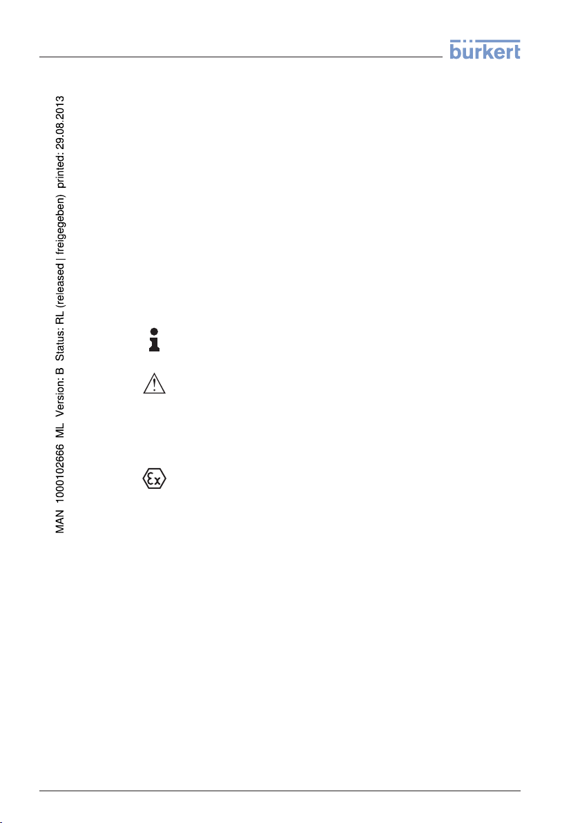
4.3 Mounting preparations, mounting strap
The mounting strap enables simple mounting on the vessel wall or silo
top. It is suitable for wall, ceiling or boom mounting. Especially in open
vessels this is a very easy and effective way to align the sensor to the
bulk solid surface.
The strap is supplied unassembled and must be screwed to the sensor
before setup with three hexagon screws M5 x 10 and spring washers.
Max. torque, see chapter "Technical data". Required tools: Allen
wrench size 4.
There are two ways to screw the strap onto the sensor. Depending on
the selected version, the sensors can be swivelled in the strap as
follows:
l Single chamber housing
- Angle of inclination 180°, infinitely variable
- Angle of inclination in three steps 0°, 90° and 180°
l Double chamber housing
- Angle of inclination 90°, infinitely variable
- Angle of inclination in two steps 0° and 90°
41783-EN-120316
LEVEL TRANSMITTER 8136 • 4 … 20 mA/HART - two-wire 11
Page 12
4 Mounting
Fig. 3: Adjustment of the angle of inclination
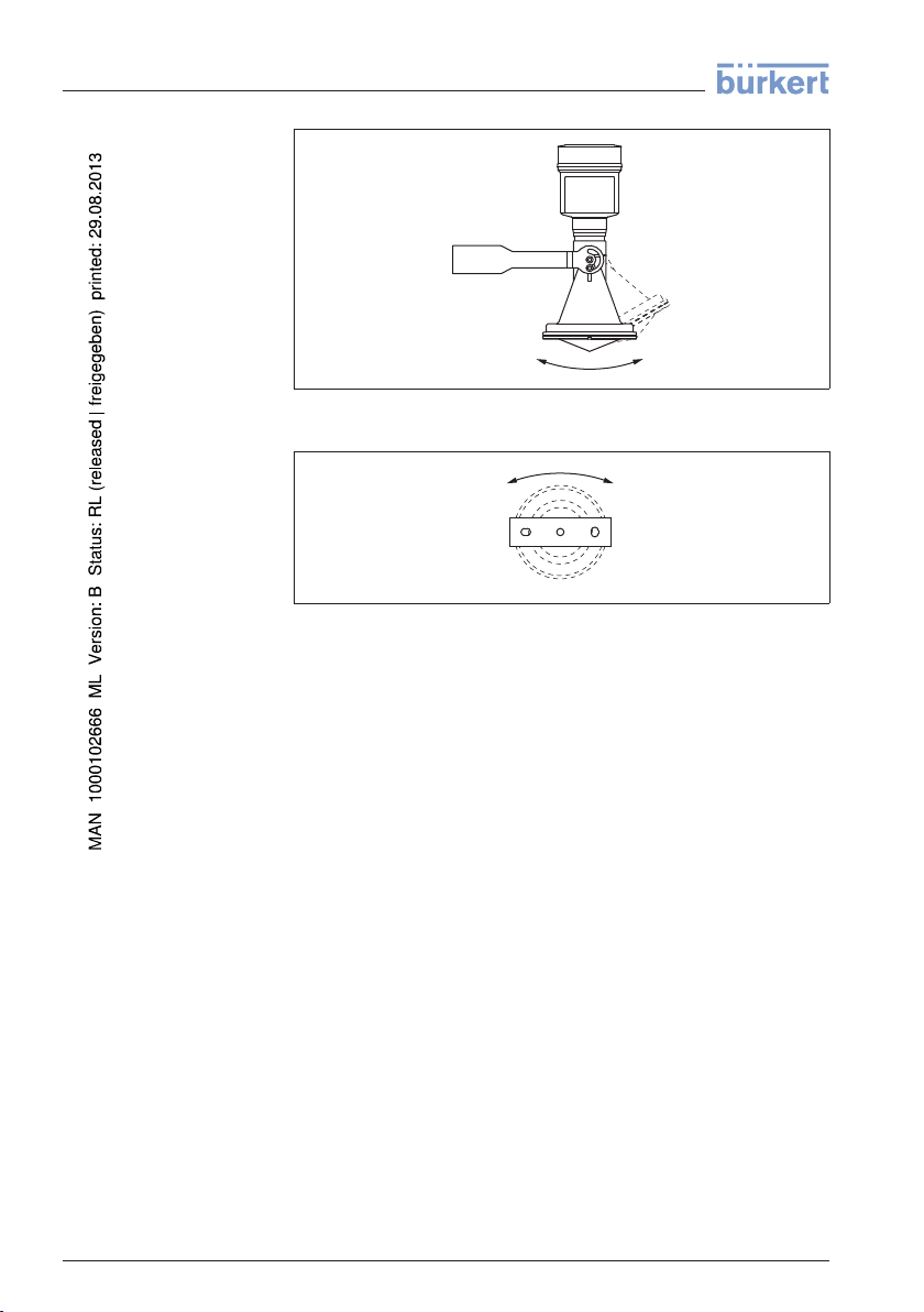
Fig. 4: Turning by fastening in the centre
4.4 Instructions for installation
Ti
ght installation of the
plastic horn antenna
Polaris
ation plane
12 LEVEL TRANSMITTER 8136 • 4 … 20 mA/HART - two-wire
For tight installation of the version with plastic horn antenna with
compression or adapter flange, the following conditions must be
fulfilled:
1 Use suitable flat seal, e.g. of EPDM with Shore hardness 25 or 50
2 Make sure the number of flange screws corresponds to the
number of flange holes
3 Tighten all screws with the torque stated in the technical data
The emitted radar impulses of the radar sensor are electromagnetic
waves. The polarisation plane is the direction of the electrical wave
component. By turning the instrument in the connection flange or
mounting boss, the polarisation can be used to reduce the effects of
false echoes.
The position of the polarisation plane is marked on the process fitting
of the instrument.
41783-EN-120316
Page 13

1
1
4 Mounting
Fig. 5: P osition of the polarisation plane with LEVEL TRANSMITTER 8136 with
encapsulated antenna system
1 Marking hole
Fig. 6: P osition of the polarisation plane with LEVEL TRANSMITTER 8136 with
plastic horn antenna
1 Marking bars
Mountin
g position
When mounting the sensor, keep a distance of at least 200 mm
(7.874 in) to the vessel wall. If the sensor is installed in the center of
dished or round vessel tops, multiple ec hoes can arise. These can,
however, be suppressed by an appropriate adjustment (see chapter
"Setup").
If you cannot keep this distance you should carry out a false echo
storage before setup. This applies mainly if buildup on the vessel wall
is expected. In this case, w e recommend repeating a false echo
storage later with existing buildup.
41783-EN-120316
LEVEL TRANSMITTER 8136 • 4 … 20 mA/HART - two-wire 13
Page 14

> 200 mm
(7.87
")
4 Mounting
Fig. 7: Mounting of the radar sensor on round vessel tops
In vessels with conical bottom it can be advantageous to mount the
sensor in the center of the vessel, as measurement is then possible
down to the lowest point of the vessel bottom.
Fig. 8: Mounting of the radar sensor on vessels with conical bottom
Inflow
ing medium
Do not mount the instruments in or above the filling stream. Make sure
that you detect the product surface, not the inflowing product.
14 LEVEL TRANSMITTER 8136 • 4 … 20 mA/HART - two-wire
41783-EN-120316
Page 15
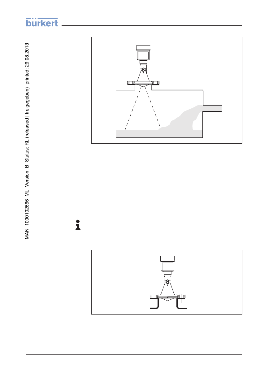
Fig. 9: Mounting of the radar sensor with inflowing medium
4 Mounting
ket with plastic horn
Soc
antenna
A corresponding collar flange for DN 80 (ASME 3" or JIS 80) as well as
a suitable adapter flange are available for mounting LEVEL TRANS-
MITTER 8136.
With the housing versions plastic, aluminium single chamber and
stainless steel, the collar flange can be placed directly over the
housing. With the aluminium double chamber housing, retroactive
mounting in this way is not possible - the mounting type must be
specified with the order.
Information:
The socket should be as short as possible and the socket end should
be rounded. Interfering reflections from the vessel socket are thus
minimised.
Fig. 10: Recommended socket mounting
41783-EN-120316
LEVEL TRANSMITTER 8136 • 4 … 20 mA/HART - two-wire 15
Page 16

d
h
4 Mounting
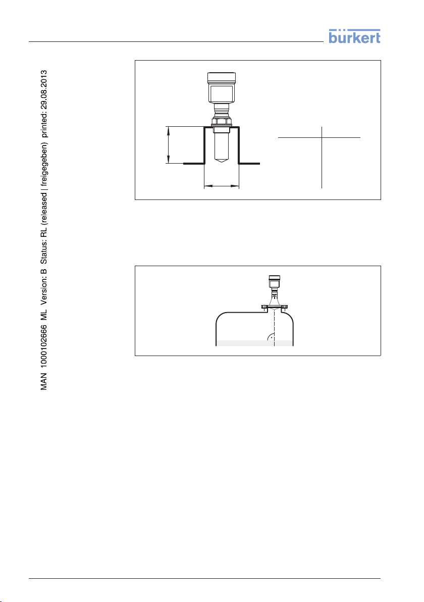
If the medium has good reflective properties, LEVEL TRANSMITTER
8136 can also be mounted on a longer socket piece. Recommended
values for socket heights are specified in the following illustration. You
must carry out a false echo storage afterwards.
The below charts specify the max. socket piece length h depending on
the diameter d.
Socket diameter d Socket length h
80 mm 300 mm
100 mm 400 mm
150 mm 500 mm
Socket diameter d Socket length h
3" 11.8 in
4" 15.8 in
6" 19.7 in
Tip:
In new facilities it is useful to incline the vessel socket in the direction
of the outlet. False reflections from the vessel wall are thus reduced
and measurement all the way down to the bottom of the conical outlet
is possible.
16 LEVEL TRANSMITTER 8136 • 4 … 20 mA/HART - two-wire
41783-EN-120316
Page 17

Fig. 12: Alignment in silos
ca. 10 mm
4 Mounting
ket with encapsu-
Soc
lated antenna system
The socket piece should be dimensioned in such a way that the
antenna end protrudes at least 10 mm (0.4 in) out of the socket.
Fig. 13: Recommended socket mounting
If the reflective properties of the medium are good, you can mount
LEVEL TRANSMITTER 8136 on sockets which are higher than the
length of the antenna. You will find recommended values for socket
heights in the following illustration. The socket end should be smooth
and burr-free, if possible also rounded. After installation you must carry
out a false echo storage.
41783-EN-120316
LEVEL TRANSMITTER 8136 • 4 … 20 mA/HART - two-wire 17
Page 18
d
h
d
h
1½"
50 mm/2"
80 mm/3"
100 mm/4"
150 mm/6"
200 mm
250 mm
300 mm
500 mm
800 mm
4 Mounting
Fig. 14: Deviating socket dimensions
Sen
sor orientation
Vess
el installations
Align the sensor in liquids as vertical as possible to the product surface
to achieve optimum measurement results.
Fig. 15: Alignment in liquids
The mounting location of the radar sensor should be a place where no
other equipment or fixtures cross the path of the microwave signals.
Vessel installations, such as e.g. ladders, limit switches, heating
spirals, struts, etc., can cause false echoes and impair the useful echo.
Make sure when planning your measuring site that the radar sensor
has a "clear view" to the measured product.
In case of existing vessel installations, a false echo storage should be
carried out during setup.
If large vessel installations such as struts or supports cause false
echoes, these can be attenuated through supplementary measures.
Small, inclined sheet metal baffles above the installations scatter the
radar signals and prevent direct interfering reflections.
41783-EN-120316
18 LEVEL TRANSMITTER 8136 • 4 … 20 mA/HART - two-wire
Page 19

Fig. 16: Cover smooth profiles with deflectors
4 Mounting
Agitato
Foam
rs
generation
If there are agitators in the vessel, a false signal memory should be
carried out with the agitators in motion. This ensures that the interfering
reflections from the agitators are saved with the blades in different
positions.
Fig. 17: Agitators
Through the action of filling, stirring and other processes in the vessel,
compact foams that considerably damp the emitted signals may form
on the product surface.
If foams are causing measurement errors, the biggest possible radar
antennas, the electronics with increased sensitivity or low frequency
radar sensors (C band) should be used.
As an alternative, sensors with guided microwave can be used. These
are unaffected by foam generation and are best suited for such
applications.
41783-EN-120316
LEVEL TRANSMITTER 8136 • 4 … 20 mA/HART - two-wire 19
Page 20

1
2
3
100%
4
5
8
6
7
0%
9
4 Mounting
rement in a surge
Measu
pipe
When using a surge pipe in a vessel, influences from vessel
installations and turbulences can be excluded. Under these prerequisites, the measurement of products with low dielectric values (ε
r
value ≥ 1.6) is possible. In very adhesive products, measurement in a
surge pipe is not recommended.
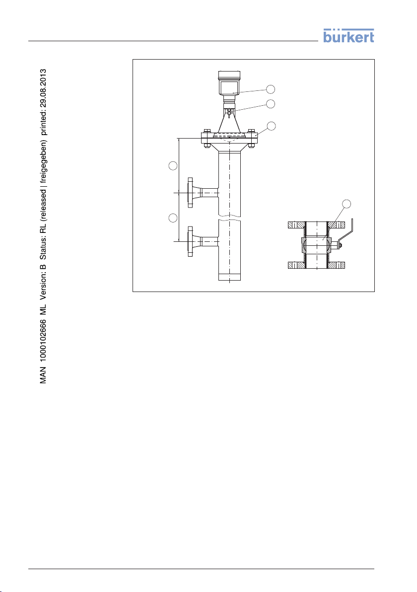
Fig. 18: Configuration surge pipe
1 Radar sensor
2 Marking of the polarisation direction
3 Thread or flange on the instrument
4 Vent hole
5 Holes
6 Weld joint
20 LEVEL TRANSMITTER 8136 • 4 … 20 mA/HART - two-wire
7 Welding neck flange
8 Ball valve with complete opening
9 Fastening of the surge pipe
Instructions for orientation:
l Note marking of the polarisation plane on the sensor
l With threaded fitting, the marking is on the hexagon, with flange
connection between the two flange holes
l All holes in the surge pipe must be in one plane with this marking
Instructions for the measurement:
41783-EN-120316
Page 21

4 Mounting
l The 100 % point must be below the upper vent hole and the
antenna edge
l The 0 % point is the end of the surge pipe
l The tube diameter must be at least DN 40 or 1½" with antenna
size 40 mm (1½")
l For the parameter adjustment, select "Application standpipe" and
enter the tube diameter to compensate errors due to running time
shift
l A false signal suppression with integrated sensor is recommended
but not mandatory
l The measurement through a ball valve with complete run is
possible
Constructional requirements on the surge pipe:
l Material metal, smoother inner tube
l Preferably pultruded or straight beaded stainless steel tube
l Welded joint should be straight and lie in one axis with the holes
l Flanges are welded to the tube according to the orientation of the
polarisation level
l In case of a extension with a welding neck flange or pipe collar as
well as when a ball valve is used, the inner surfaces should be
aligned and accurately joined together
l Gap size with junctions ≤ 0.1 mm
l Do not weld through the pipe wall. The surge pipe must remain
smooth inside. Roughness and beads on the inside caused by
unintentional penetration should be removed since they cause
strong false echoes and encourage buildup
l Surge pipes must extend all the way down to the requested min.
level, as measurement is only possible within the tube
l Diameter of holes ≤ 5 mm, any number OK, on one side or
completely through
l The antenna diameter of the sensor should correspond to the
inner diameter of the tube
l Diameter should be constant over the complete length
Measu
rement in the by-
pass
An alternative to measurement in a surge pipe is measurement in a
bypass tube outside of the vessel.
41783-EN-120316
LEVEL TRANSMITTER 8136 • 4 … 20 mA/HART - two-wire 21
Page 22
0 %
100 %
1
2
5
4
3
6
4 Mounting
Fig. 19: Configuration bypass
1 Radar sensor
2 Marking of the polarisation direction
3 Instrument flange
4 Distance sensor reference plane to upper tube connection
5 Distance of the tube connections
6 Ball valve with complete opening
Instructions for orientation:
l Note marking of the polarisation plane on the sensor
l With threaded fitting, the marking is on the hexagon, with flange
connection between the two flange holes
l The pipe connections to the vessel must be in one plane with this
marking
Instructions for the measurement:
l The 100 % point must not be above the upper tube connection to
the vessel
l The 0 % point must not be below the lower tube connection to the
vessel
l Min. distance sensor reference plane to the upper edge upper
tube connection > 300 mm
l The tube diameter must be at least DN 40 or 1½" with antenna
size 40 mm (1½")
l For the parameter adjustment, select "Application standpipe" and
enter the tube diameter to compensate errors due to running time
shift
41783-EN-120316
22 LEVEL TRANSMITTER 8136 • 4 … 20 mA/HART - two-wire
Page 23

h
max
d
min
≥ 2 mm x h
max
90°
4
3 ... 4 h
max
≥ 50 mm
90
°
2
3
1
4 Mounting
l A false signal suppression with integrated sensor is recommended
but not mandatory
l The measurement through a ball valve with complete run is
possible
Constructional requirements on the bypass pipe:
l Material metal, smoother inner tube
l In case of an extremely rough tube inner surface, use an inserted
tube (tube in tube) or a radar sensor with tube antenna
l Flanges are welded to the tube according to the orientation of the
polarisation level
l Gap size with junctions ≤ 0.1 mm, for example, when using a ball
valve or intermediate flanges with single pipe sections
l The antenna diameter of the sensor should correspond to the
inner diameter of the tube
l Diameter should be constant over the complete length
ow measurement with
Fl
rectangular flume
The short examples give you introductory information on the flow
measurement. Detailed planning information is available from flume
manufacturers and in special literature.
Fig. 20: Flow measurement with rectangular flume: d
sensor (see chapter "Technical data"); h
flume
= max. filling of the rectangular
max.
1 Overflow orifice (side view)
2 Headwater
3 Tail water
4 Overfall orifice (view from bottom water)
= min. distance of the
min.
In general, the following points must be observed:
l Install the sensor on the headwater side
l Installation in the centre of the flume and vertical to the liquid
surface
l Distance to the overfall orifice
l Distance of orifice opening above ground
l Min. distance of the orifice opening to bottom water
41783-EN-120316
LEVEL TRANSMITTER 8136 • 4 … 20 mA/HART - two-wire 23
l Min. distance of the sensor to max. storage level
Page 24

2
3 ... 4 x h
max
90°
h
max
d
1
B
4 Mounting
Fl
ow measurement with
Khafagi Venturi flume
Fig. 21: Flow measurement with Khafagi-Venturi flume: d = Min. distance to
sensor; h
= max. filling of the flume; B = tightest constriction in the flume
max.
1 Position sensor
2 Venturi flume
In general, the following points must be observed:
l Installation of the sensor at the inlet side
l Installation in the centre of the flume and vertical to the liquid
surface
l Distance to the Venturi flume
l Min. distance of the sensor to max. storage level
41783-EN-120316
24 LEVEL TRANSMITTER 8136 • 4 … 20 mA/HART - two-wire
Page 25

5 Connecting to power supply
5 Connecting to power supply
5.1 Preparing the connection
Saf
ety instructions
Volta
ge supply
Conne
ction cable
Always keep in mind the following safety instructions:
l Connect only in the complete absence of line voltage
l If voltage surges are expected, install overvoltage arresters
Power supply and current signal are carried on the same two-wire
cable. The voltage supply range can differ depending on the
instrument version.
The data for power supply are specified in chapter "Technical data".
Provide a reliable separation between the supply circuit and the mains
circuits according to DIN VDE 0106 part 101.
Keep in mind the following additional factors that influence the
operating voltage:
l Output voltage of the power supply unit can be lower under
nominal load (with a sensor current of 20.5 mA or 22 mA in case of
fault message)
l Influence of additional instruments in the circuit (see load values in
chapter "Technical data")
The instrument is connected with standard two-wire cable without
screen. If electromagnetic interference is expected which is above the
test values of EN 61326-1 for industrial areas, screened cable should
be used.
For instruments with housing and cable gland, use cable with round
cross-section. A cable outer diameter of 5 … 9 mm (0.2 … 0.35 in)
ensures the seal effect of the cable gland. If you are using cable with a
different diameter, exchange the seal or use a suitable cable gland.
We generally recommend the use of screened cable for HART
multidrop mode.
Cable
gland ½ NPT
Cable
screening and
grounding
With plastic housing, the NPT cable gland or the Conduit steel tube
must be screwed without grease into the threaded insert.
Max. torque for all housings see chapter "Technical data"
If screened cable is necessary, connect the cable screen on both ends
to ground potential. In the sensor, the screen must be connected
directly to the internal ground terminal. The ground terminal on the
outside of the housing must be connected to the potential equalisation
(low impedance).
41783-EN-120316
LEVEL TRANSMITTER 8136 • 4 … 20 mA/HART - two-wire 25
Page 26

5 Connecting to power supply
Cable
screening and
grounding
If potential equalisation currents are expected, the connection on the
processing side must be made via a ceramic capacitor (e. g. 1 nF,
1500 V). The low frequency potential equalisation currents are thus
suppressed, but the protective effect against high frequency interference signals remains.
If screened cable is necessary, connect the cable screen on both ends
to ground potential. In the sensor, the screen must be connected
directly to the internal ground terminal. The ground terminal on the
outside of the housing must be connected to the potential equalisation
(low impedance).
If potential equalisation currents are expected, the connection on the
processing side must be made via a ceramic capacitor (e. g. 1 nF,
1500 V). The low frequency potential equalisation currents are thus
suppressed, but the protective effect against high frequency interference signals remains.
5.2 Connect
Conne
ction technology
Conne
ction procedure
The voltage supply and signal output are connected via the springloaded terminals in the housing.
The connection to the indicating and adjustment module or to the
interface adapter is carried out via contact pins in the housing.
Proceed as follows:
1 Unscrew the housing cover
2 If an indicating and adjustment module is installed, remove it by
turning it slightly to the left.
3 Loosen compression nut of the cable entry
4 Remove approx. 10 cm (4 in) of the cable mantle, strip approx.
1 cm (0.4 in) of insulation from the ends of the individual wires
41783-EN-120316
26 LEVEL TRANSMITTER 8136 • 4 … 20 mA/HART - two-wire
Page 27

5 Connecting to power supply
5 Insert the cable into the sensor through the cable entry
Fig. 22: Connection steps 5 and 6
6 Insert the wire ends into the terminals according to the wiring plan
Information:
Solid cores as well as flexible cores with cable end sleeves are
inserted directly into the terminal openings. In case of flexible cores
without end sleeves, press the terminal head with a small screwdriver;
the terminal opening is freed. When the screwdriver is released, the
terminal closes again.
7 Check the hold of the wires in the terminals by lightly pulling on
them
8 Connect the screen to the internal ground terminal, connect the
outer ground terminal to potential equalisation
9 Tighten the compression nut of the cable entry. The seal ring must
completely encircle the cable
10 Screw the housing cover back on
The electrical connection is finished.
Information:
The terminal block is pluggable and can be removed from the
electronics. To do this, lift the terminal block with a small screwdriver
and pull it out. When inserting the terminal block again, you should
hear it snap in.
5.3 Wiring plan
The following illustration applies to the non-Ex as well as to the Ex-ia
version.
41783-EN-120316
LEVEL TRANSMITTER 8136 • 4 … 20 mA/HART - two-wire 27
Page 28

5
1
2
+
( )
(-)
6 7 8
4...20mA
2
3
4
1
5 Connecting to power supply
nics compart-
Electro
ment
Fig. 23: Electronics and connection compartment, single chamber housing
1 Voltage supply, signal output
2 For indicating and adjustment module or interface adapter
3 For external indicating and adjustment unit
4 Ground terminal for connection of the cable screen
5.4 Switch-on phase
After connecting the instrument to power supply or after a voltage
recurrence, the instrument carries out a self-check for approx. 30 s:
l Internal check of the electronics
l Indication of the instrument type, hardware and software version,
measurement loop name on the display or PC
l Indication of the status message "F 105 Determine measured
value" on the display or PC
l The output signal jumps to the set error current
As soon as a plausible measured value is found, the corresponding
current is outputted to the signal cable. The value corresponds to the
actual level as well as the settings already carried out, e.g. factory
setting.
28 LEVEL TRANSMITTER 8136 • 4 … 20 mA/HART - two-wire
41783-EN-120316
Page 29

6 Set up with the indicating and adjustment module
6 Set up with the indicating and adjustment
module
6.1 Insert indicating and adjustment module
The indicating and adjustment module can be inserted into the sensor
and removed any time. Four positions displaced by 90° can be
selected. It is not necessary to interrupt the power supply.
Proceed as follows:
1 Unscrew the housing cover
2 Place the indicating and adjustment module in the requested
position onto the electronics and turn to the right until it snaps in
3 Screw housing cover with inspection window tightly back on
Removal is carried out in reverse order.
The indicating and adjustment module is powered by the sensor, an
additional connection is not necessary.
Fig. 24: Insertion of the indicating and adjustment module with single chamber
housing
Note:
If you intend to retrofit the instrument with an indicating and adjustment
module for continuous measured value indication, a higher cover with
an inspection glass is required.
41783-EN-120316
LEVEL TRANSMITTER 8136 • 4 … 20 mA/HART - two-wire 29
Page 30

1
2
6 Set up with the indicating and adjustment module
6.2 Adjustment system
Fig. 25: Indicating and adjustment elements
1 LC display
2 Adjustment keys
Key
functions
l [OK] key:
- Move to the menu overview
- Confirm selected menu
- Edit parameter
- Save value
l [->] key:
- Presentation change measured value
- Select list entry
- Select editing position
l [+] key:
- Change value of the parameter
l [ESC] key:
- interrupt input
- Return to higher-ranking menu
Adjus
tment system
The sensor is adjusted via the four keys of the indicating and
adjustment module. The LC display indicates the individual menu
items. The functions of the individual keys are shown in the above
illustration. Approx. 10 minutes after the last pressing of a key, an
automatic reset to measured value indication is triggered. Any values
not confirmed with [OK] will not be sa ved.
30 LEVEL TRANSMITTER 8136 • 4 … 20 mA/HART - two-wire
41783-EN-120316
Page 31
Main
menu
6 Set up with the indicating and adjustment module
6.3 Parameter adjustment
Through the parameter adjustment the instrument is adapted to the
application conditions. The parameter adjustment is carried out via an
adjustment menu.
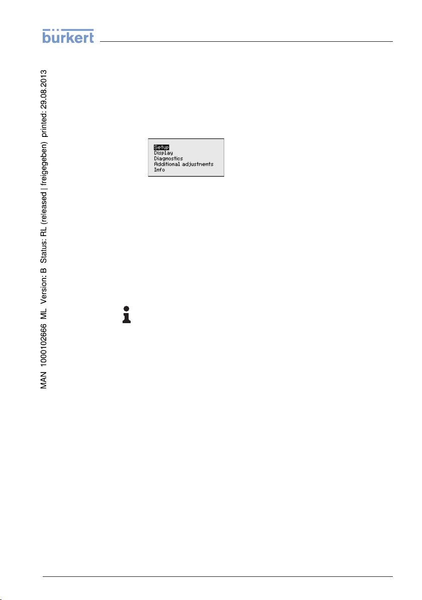
The main menu is divided into five sections with the following
functions:
Setup: Settings, e.g., for measurement loop name, medium, applica-
tion, vessel, adjustment, signal output
Display: Settings, e.g., for language, measured value display, lighting
Diagnosis: Information, e.g. on the instrument status, pointer,
reliability, simulation, echo curve
Further settings: Instrument unit, false signal suppression, linear-
isation curve, reset, date/time, reset, copy function
Info: Instrument name, hardware and software version, calibration
date, instrument features
Information:
In this operating instructions manual, the instrument-specific parameters in the menu sections "Setup", "Diagnosis" and "Additional
settings" are described. The general parameters in these menu
section are described in the operating instructions manual "Indicating
and adjustment module".
You can find in the operating instructions manual "Indicating and
adjustment module" also the description of the menu sections
"Display" and "Info".
In the main menu point "Setup", the individual submenu points should
be selected subsequently and provided with the correct parameters to
ensure the optimum adjustment of the measurement. The procedure is
described in the following.
Set
up/Medium
41783-EN-120316
LEVEL TRANSMITTER 8136 • 4 … 20 mA/HART - two-wire 31
Each medium has different reflection properties. With liquids, further
interfering factors are fluctuation pr oduct surface and foam generation.
With bulk solids, these are dust generation, material cone and
additional echoes from the vessel wall.
To adapt the sensor to these different measuring conditions, the
selection "Liquid" or "Bulk solid" should be made in this menu item.
Page 32

6 Set up with the indicating and adjustment module
Through this selection, the sensor is adapted perfectly to the product
and measurement reliability, particularly in products with poor
reflective properties, is considerably increased.
Enter the requested parameters via the appropriate keys, save your
settings with [OK] and jump to the next menu item with the [ESC] and
the [->] key.
up/Application
Set
In addition to the medium, also the application, i.e. the measuring site,
can influence the measurement.
With this menu item, the sensor can be adapted to the applications.
The adjustment possibilities depend on the selection "Liquid" or "Bulk
solid" under "Medium".
The following options are available when "Liquid" is selected:
The selection "Standpipe" opens a new window in which the inner
diameter of the applied standpipe is entered.
41783-EN-120316
The following features form the basis of the applications:
Storage tank:
l Setup: large-volumed, upright cylindrical, spherical
32 LEVEL TRANSMITTER 8136 • 4 … 20 mA/HART - two-wire
Page 33

6 Set up with the indicating and adjustment module
l Product speed: slow filling and emptying
l Process/measurement conditions:
- Condensation
- Smooth product surface
- Max. requirement to the measurement accuracy
Storage tanke with product circulation:
l Setup: large-volumed, upright cylindrical, spherical
l Product speed: slow filling and emptying
l Vessel: small laterally mounted or large top mounted stirrer
l Process/measurement conditions:
- Relatively smooth product surface
- Max. requirement to the measurement accuracy
- Condensation
- Slight foam generation
- Overfilling possible
Storage tank on ships (Cargo Tank):
l Product speed: slow filling and emptying
l Vessel:
- Installations in the bottom section (bracers, heating spirals)
- High sockets 200 … 500 mm, also with large diameters
l Process/measurement conditions:
- Condensation, buildup by movement
- Max. requirement on measurement accuracy from 95 %
Stirrer vessel (reactor):
l Setup: all vessel sizes possible
l Product speed:
- Fast to slow filling possible
- Vessel is very often filled and emptied
l Vessel:
- Socket available
- Large agitator blades of metal
- Vortex breakers, heating spirals
l Process/measurement conditions:
- Condensation, buildup by movement
- Strong spout generation
- Very agitated surface, foam generation
Dosing vessel:
l Setup: all vessel sizes possible
l Product speed:
- Fast filling and emptying
- Vessel is very often filled and emptied
l Vessel: narrow installation situation
l Process/measurement conditions:
- Condensation, buildup on the antenna
- Foam generation
41783-EN-120316
LEVEL TRANSMITTER 8136 • 4 … 20 mA/HART - two-wire 33
Page 34

6 Set up with the indicating and adjustment module
Standpipe:
l Product speed: very fast filling and emptying
l Vessel:
- Vent hole
- Joins like flanges, weld joints
- Shifting of the running time in the tube
l Process/measurement conditions:
- Condensation
- Buildup
Bypass:
l Product speed:
- Fast up to slow filling with short up to long bypass tube
possible
- Often the level is hold via a control facility
l Vessel:
- Lateral outlets and inlets
- Joins like flanges, weld joints
- Shifting of the running time in the tube
l Process/measurement conditions:
- Condensation
- Buildup
- Separation of oil and water possible
- Overfilling into the antenna possible
Plastic tank:
l Vessel:
- Measurement fix mounted or integrated
- Measurement depending on the application through the vessel
top
- With empty vessel, the measurement can be carried out
through the bottom
l Process/measurement conditions:
- Condensation on the plastic ceiling
- In outside facilities water and snow on the vessel top possible
Transportable plastic tank:
l Vessel:
- Material and thickness different
- Measurement through the vessel top
l Process/measurement conditions:
- Measured value jump with vessel change
Open water (gauge measurement):
l Gauge rate of change: slow gauge change
l Process/measurement conditions:
- Distance sensor to water surface to big
- Extreme damping of output signal due to wave generation
41783-EN-120316
34 LEVEL TRANSMITTER 8136 • 4 … 20 mA/HART - two-wire
Page 35

6 Set up with the indicating and adjustment module
- Ice and condensation on the antenna possible
- Spiders and insect nestle in the antennas
- Floating material and animals sporadically on the water
surface
Open flume (flow measurement):
l Gauge rate of change: slow gauge change
l Process/measurement conditions:
- Ice and condensation on the antenna possible
- Spiders and insect nestle in the antennas
- Smooth water surface
- Exact measurement result required
- Distance to the water surface normally relatively high
Rain water overfall (weir):
l Gauge rate of change: slow gauge change
l Process/measurement conditions:
- Ice and condensation on the antenna possible
- Spiders and insect nestle in the antennas
- Turbulent water surface
- Sensor flooding possible
Demonstration:
l Adjustment for all applications which are not typically level
measurement
l Sensor accepts all measured value changes within the measuring
range immediately
l Typical applications:
- Instrument demonstration
- Object recognition/monitoring (additional settings required)
Caution:
If a separation of liquids with different dielectric figure occurs in the
vessel, for example through condensation, the radar sensor can detect
under certain circumstances only the medium with the higher dielectric
figure. Keep in mind that layer interfaces can cause faulty measurements.
If you want to measure the total height of both liquids reliably, please
contact our service department or use an instrument specially
designed for interface measurement.
The following options are available when "Bulk solid" is selected:
The following features form the basis of the applications:
Silo (slim and high):
41783-EN-120316
LEVEL TRANSMITTER 8136 • 4 … 20 mA/HART - two-wire 35
Page 36

6 Set up with the indicating and adjustment module
l Vessel of metal: weld joints
l Process/measurement conditions:
- Filling too close to the sensor
- System noise with completely empty silo increased
- Automatic false signal suppression with partly filled vessel
Bunker (large-volumed):
l Vessel of concrete or metal:
- Structured vessel walls
- Installations present
l Process/measurement conditions:
- Large distance to the medium
- Large angles of repose
Bunker with fast filling:
l Vessel of concrete or metal, also multiple chamber silo:
- Structured vessel walls
- Installations present
l Process/measurement conditions:
- Measured value jumps, e.g. by truck loading
- Large distance to the medium
- Large angles of repose
Heap:
l Sensor mounting on movable conveyor belts
l Detection of the heap profile
l Height detection during filling
l Process/measurement conditions:
- Measured value jumps, e.g. by the profile of the heap or
traverses
- Large angles of repose
- Measurement near the filling stream
Crusher:
l Vessel: installations, wear and protective facilities available
l Process/measurement conditions:
- Measured value jumps, e.g. by truck loading
- Fast reaction time
- Large distance to the medium
Demonstration:
l Adjustment for all applications which are not typically level
measurement
l Sensor accepts all measured value changes within the measuring
range immediately
l Typical applications:
- Instrument demonstration
- Object recognition/monitoring (additional settings required)
41783-EN-120316
36 LEVEL TRANSMITTER 8136 • 4 … 20 mA/HART - two-wire
Page 37

6 Set up with the indicating and adjustment module
Through this selection, the sensor is adapted optimally to the
application or the location and measurement reliability under the
various basic conditions is increased considerably.
Enter the requested parameters via the appropriate keys, save your
settings with [OK] and jump to the next menu item with the [ESC] and
the [->] key.
up/Vessel height,
Set
measuring range
Set
up/Vessel form
With this selection, the operating range of the sensor is adapted to the
vessel height and the reliability with different frame conditions is
increased considerably.
Independent from this, the min. adjustment must be carried out.
Enter the requested parameters via the appropriate keys, save your
settings with [OK] and jump to the next menu item with the [ESC] and
the [->] key.
Also the vessel form can influence the measurement apart from the
medium and the application. To adapt the sensor to these measurement conditions, this menu item offers you different options for vessel
bottom and ceiling in case of certain applications.
Enter the requested parameters via the appropriate keys, save your
settings with [OK] and jump to the next menu item with the [ESC] and
the [->] key.
Set
up/Adjustment
Because a radar sensor is a distance measuring instrument, the
distance from the sensor to the product surface is measured. To have
the real product level displayed, an allocation of the measured
distance to the percentage height must be made. To carry out this
adjustment, the distance is entered with full and empty vessel. If these
values are not known, an adjustment with the distance values, e.g.
10 % and 90 % is also possible. Starting point for these distance
specifications is always the seal surface of the thread or flange. By
means of these settings, the real level is calculated.
41783-EN-120316
LEVEL TRANSMITTER 8136 • 4 … 20 mA/HART - two-wire 37
Page 38

6 Set up with the indicating and adjustment module
The real product level during this adjustment is not important, because
the min./max. adjustment is always carried out without changing the
product level. These settings can be made ahead of time without the
instrument having to be installed.
Setup/Min. adjustment
Set
up/Max. adjustment
Proceed as follows:
1 Select the menu item "Setup" with [->] and confirm with [OK]. Now
select with [->] the menu item "Min. adjustment" and confirm with
[OK].
2 Edit the percentage value with [OK] and set the cursor to the
requested position with [->].
3 Set the requested percentage value with [+] and save with [OK].
The cursor jumps now to the distance value.
4 Enter the suitable distance value in m for the empty vessel (e.g.
distance from the sensor to the vessel bottom) corresponding to
the percentage value.
5 Save settings with [OK] and move with [ESC] and [->] to the max.
adjustment.
Proceed as follows:
1 Select with [->] the menu item max. adjustment and confirm with
[OK].
2 Prepare the percentage value for editing with [OK] and set the
cursor to the requested position with [->].
38 LEVEL TRANSMITTER 8136 • 4 … 20 mA/HART - two-wire
41783-EN-120316
Page 39

6 Set up with the indicating and adjustment module
3 Set the requested percentage value with [+] and save with [OK].
The cursor jumps now to the distance value.
4 Enter the appropriate distance value in m (corresponding to the
percentage value) for the full vessel. Keep in mind that the max.
level must lie below the min. distance to the antenna edge.
5 Save settings with [OK]
sis/Peak value
Diagno
Diagno
sis/Measurement
reliability
Diagno
ses/Curve indica-
tion
Min. and max. measured values are saved in the sensor. The values
are displayed in the menu item "Peak values".
When non-contact level sensors are used, the measurement can be
influenced by the respective process conditions. In this menu item, the
measurement reliability of the level echo is displayed as dB value. The
measurement reliability equals signal strength minus noise. The higher
the value, the more reliable the measurement. With a functioning
measurement, the values are > 10 dB.
The "Echo curve" shows the signal strength of the echoes over the
measuring range in dB. The signal strength enables an evaluation of
the quality of the measurement.
The "False signal suppression" displays the saved false echoes (see
menu "Additional settings") of the empty vessel with signal strength in
"dB" over the measuring range.
41783-EN-120316
LEVEL TRANSMITTER 8136 • 4 … 20 mA/HART - two-wire 39
Page 40

6 Set up with the indicating and adjustment module
A comparison of echo curve and false signal suppression allows a
more accurate conclusion on measurement reliability. The selected
curve is continuously updated. With the [OK] key, a submenu with
zoom functions is opened:
l "X-Zoom": Zoom function for the meas. distance
l "Y-Zoom": 1, 2, 5 and 10x signal magnification in "dB"
l "Unzoom": Reset the presentation to the nominal measuring range
with single magnification
sis/Echo curve
Diagno
memory
Fur
ther settings/False
signal suppression
With the function "Echo curve memory" the echo curve can be saved
at the time of setup. This is generally recommended; for using the
Asset Management functions it is absolutely necessary. If possible, the
curve should be saved with a low level in the vessel.
With the adjustment software PACTware and the PC, the high
resolution echo curve can be displayed and used to recognize signal
changes over the operating time. In addition, the echo curve of the
setup can be also displayed in the echo curve window and compared
with the actual echo curve.
The following circumstances cause interfering reflections and can
influence the measurement:
l High sockets
l Vessel installations such as struts
l Agitators
l Buildup or welded joints on vessel walls
Note:
A false signal suppression detects, marks and saves these false
signals so that they are no longer taken into account for level
measurement.
This should be done with a low level so that possible interfering
reflections can be detected.
Proceed as follows:
41783-EN-120316
40 LEVEL TRANSMITTER 8136 • 4 … 20 mA/HART - two-wire
Page 41

6 Set up with the indicating and adjustment module
1 Select the menu item "Additional settins" with [->] and confirm with
[OK]. With [->] you have to select the menu item "False signal
suppression" and confirm with [OK].
2 Confirm again with [OK].
3 Confirm again with [OK].
4 Confirm again with [OK] and enter the actual distance from the
sensor to the product surface.
5 All interfering signals in this section are detected by the sensor
and stored after confirming with [OK].
Note:
Check the distance to the product surface, because if an incorrect (too
large) value is entered, the existing level will be saved as false signal.
The filling level would then no longer be detectable in this area.
If a false signal suppression is already created in the sensor, then the
following menu window appears when selecting "False signal
suppression":
The menu item "Delete" is used to completely delete an already
created false signal suppression. This is useful if the saved false signal
suppression no longer matches the metrological conditions in the
vessel.
41783-EN-120316
LEVEL TRANSMITTER 8136 • 4 … 20 mA/HART - two-wire 41
Page 42

6 Set up with the indicating and adjustment module
The menu item "Extend" is used to extend an already created false
signal suppression. This is useful if a false signal suppression was
carried out with a too high level and not all false signals could be
detected. When selecting "Extend", the distance to the product surface
of the created false signal suppression is displayed. This value can
now be changed and the false signal suppression can be extended to
this range.
ther settings/Lineari-
Fur
zation curve
A linearization is necessary for all vessels in which the vessel volume
does not increase linearly with the level - e.g. in a horizontal cylindrical
or spherical tank - and the indication or output of the volume is
required. Corresponding linearization curves are preprogrammed for
these vessels. They represent the correlation between the level
percentage and vessel volume.
By activating the appropriate curve, the volume percentage of the
vessel is displayed correctly. If the volume should not be displayed in
percent but e.g. in l or kg, a scaling can be also set in the menu item
"Display".
Enter the requested parameters via the appropriate keys, save your
settings and jump to the next menu item with the [ESC] and [->] key.
Caution:
Note the following if the instrument with corresponding approval is
used as part of an overfill protection system according to WHG:
If a linearisation curve is selected, the measuring signal is no longer
compulsorily linear proportional to the level. This must be taken into
consideration by the user, particularly when adjusting the switching
point on the level switch.
Addition
set
42 LEVEL TRANSMITTER 8136 • 4 … 20 mA/HART - two-wire
al settings - Re-
With a reset, certain parameter adjustments carried out by the user are
reset.
The following reset functions are available:
41783-EN-120316
Page 43
6 Set up with the indicating and adjustment module
Delivery status: Restoring the parameter settings at the time of
shipment from the factory incl. the order-specific settings. A created
false signal suppression, user-programmable linearization curve as
well as the measured value memory will be deleted.
Basic settings: Resetting the parameter settings incl. special and
laboratory parameters to the default values of the respective instrument. A created false signal suppression, user programmable
linearization curve as well as the measured value memory will be
deleted.
Setup: Resetting of the parameter settings to the default values of the
respective instrument in the menu item Setup. Order-related settings
remain but are not taken over into the current parameters. Usergenerated false signal suppression, user-programmed linearization
curve, measured value memory as well as event memory remain
untouched. The linearization is set to linear.
False signal suppression: Deleting a previously created false signal
suppression. The false signal suppression created in the factory
remains active.
Peak values measured value: Resetting of the measured min. and
max. distances to the actual measured value.
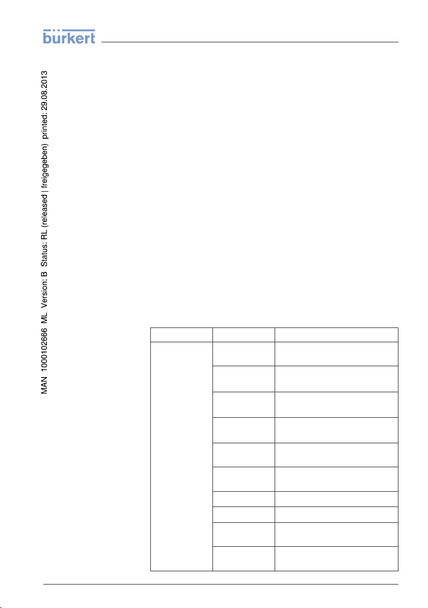
The following table shows the default values of the instrument.
Depending on the instrument version, not all menu items are available
or differently assigned:
Menu Menu
Setup Measurement
item Default value
loop name
Medium Liquid/Water
Application Storage tank
Vessel form Vessel bottom, dished boiler end
Vesell height/
Measuring range
Min. adjustment Recommended measuring range, see
Max. adjustment 0,000 m(d)
Damping 0.0 s
Current output
mode
Current output
Min./Max.
Sensor
Bulk solids/Crushed stones, gravel
Silo
Vessel top, dished boiler end
Recommended measuring range, see
"Technical data" in the supplement
"Technical data" in the supplement
4 … 20 mA, < 3.6 mA
Min. current 3.8 mA, max. current
20.5 mA
41783-EN-120316
LEVEL TRANSMITTER 8136 • 4 … 20 mA/HART - two-wire 43
Page 44

6 Set up with the indicating and adjustment module
Menu Menu item Default value
Lock operation Released
Display Language Like order
Displayed value Distance
Display unit m
Scaling size Volume
Scaling 0.00 lin %, 0 l
Lighting Switched off
Further settings Distance unit m
Temperature unit °C
Probe length Length of the standpipe Ex factory
Linearisation
curve
HART mode Standard
l
100.00 lin %, 100 l
linear
Address 0
6.4 Saving
the parameter adjustment data
We recommended noting the adjusted data, e.g. in this operating
instructions manual, and archiving them afterwards. They are thus
available for multiple use or service purposes.
If the instrument is equipped with an indicating and adjustment
module, the data in the sensor can be saved in the indicating and
adjustment module. The procedure is described in the operating
instructions manual "Indicating and adjustment module" in the menu
item "Copy sensor data". The data remain there permanently even if
the sensor power supply fails.
The following data or settings for adjustment of the indicating and
adjustment module are saved:
l All data of the menu "Setup" and "Display"
l In the menu "Additional settings" the items "Sensor-specific units,
temperature unit and linearization"
l The values of the user programmable linearisation curve
The function can also be used to transfer settings from one instrument
to another instrument of the same type. If it is necessary to exchange a
sensor, the indicating and adjustment module is inserted into the
replacement instrument and the data are likewise written into the
sensor via the menu item "Copy sensor data".
44 LEVEL TRANSMITTER 8136 • 4 … 20 mA/HART - two-wire
41783-EN-120316
Page 45

6 Set up with the indicating and adjustment module
41783-EN-120316
LEVEL TRANSMITTER 8136 • 4 … 20 mA/HART - two-wire 45
Page 46

1
3
2
5
4
7 Setup with PACTware
the interface adapter
Via
and HART
7 Setup with PACTware
7.1 Connect the PC
Fig. 26: Connecting the PC via HART to the signal cable
1 Sensor
2 HART resistance 250 Ω (optional depending on processing)
3 Connection cable with 2 mm pins and terminals
4 Processing system/PLC/Voltage supply
7.2 Parameter adjustment with PACTware
Prereq
uisites
46 LEVEL TRANSMITTER 8136 • 4 … 20 mA/HART - two-wire
For parameter adjustment of the sensor via a Windows PC, the
configuration software PACTware and a suitable instrument driver
(DTM) according to FDT standard are required. The up-to-date
PACTware version as well as all available DTMs are compiled in a
DTM Collection. The DTMs can also be integrated into other frame
applications according to FDT standard.
Note:
To ensure that all instrument functions are supported, you should
always use the latest DTM Collection. Furthermore, not all described
functions are included in older firmware versions. You can download
the latest instrument software from our homepage. A description of the
update procedure is also available in the Internet.
7.3 Saving the parameter adjustment data
We recommend documenting or saving the parameter adjustment data
via PACTware. That way the data are available for multiple use or
service purposes.
41783-EN-120316
Page 47

8 Set up with other systems
8 Set up with other systems
8.1 DD adjustment programs
Device descriptions as Enhanced Device Description (EDD) are
available for DD adjustment programs such as, for example, AMS™
and PDM.
8.2 Communicator 375, 475
Device descriptions for the instrument are available as DD or EDD for
parameter adjustment with the Field Communicator 375 or 475.
41783-EN-120316
LEVEL TRANSMITTER 8136 • 4 … 20 mA/HART - two-wire 47
Page 48

9 Diagnosis, Asset Management and service
9 Diagnosis, Asset Management and service
9.1 Maintenance
If the device is used correctly, no maintenance is required in normal
operation.
9.2 Diagnosis memory
The instrument has several memories which are available for
diagnosis purposes. The data remain even with voltage interruption.
Measu
red value memory
Event
memory
Echo
curve memory
Up to 70,000 measured values can be stored in the sensor in a ring
memory. Each entry contains date/time as well as the respective
measured value.
Stored values are for example:
l Original sensor value
l Filling height
l Measured value
l Meas. reliability
l Electronics temperature
The requested values and recording conditions are set via a PC with
PACTware/DTM or the control system with EDD. Data are thus read
out and also reset.
Up to 500 events are automatically stored with a time stamp in the
sensor (non-deletable). Each entry contains date/time, event type,
event description and value.
Event types are for example:
l Modification of a parameter
l Switching on and off times
l Status messages
l Error messages
The data are read out via a PC with PACTware/DTM or the control
system with EDD.
The echo curves are stored with date and time and the corresponding
echo data. The memory is divided into two sections:
Echo curve of the setup: This is used as reference echo curve for the
measurement conditions during setup. Changes in the measurement
conditions during operation or buildup on the antenna can thus be
recognized.
The echo curve of setup is stored via:
l PC with PACTware/DTM
l Control system with EDD
l Indicating and adjustment module
41783-EN-120316
48 LEVEL TRANSMITTER 8136 • 4 … 20 mA/HART - two-wire
Page 49

4
1
2
3
9 Diagnosis, Asset Management and service
Further echo curves: Up to 10 echo curves can be stored in a ring
buffer in this memory section.
Additional echo curves are stored via:
l PC with PACTware/DTM
l Control system with EDD
9.3 Asset Management function
The instrument features self-monitoring and diagnosis according to NE
107 and VDI/VDE 2650. In addition to the status messages in the
following tables there are more detailed error messages available
under the menu item "Diagnosis" via the indicating and adjustment
module, PACTware/DTM and EDD.
Statu
s messages
The status messages are classified in the following categories:
l Failure
l Function check
l Out of specification
l Maintenance requirement
and explained by pictographs:
Fig. 27: Pictograms of the status messages
1 Failure - red
2 Function check - orange
3 Out of specification - yellow
4 Maintenance - blue
Failure: Due to a malfunction in the instrument, a failure message is
outputted.
This status message is always active. It cannot be deactivated by the
user.
Function check: The instrument is in operation, the measured value is
temporarily invalid (for example during simulation).
This status message is always active. It cannot be deactivated by the
user.
Out of specification: The measured value is unstable because the
instrument specification is exceeded (e.g. electronics temperature).
This status message is inactive by default. It can be activated by the
user via PACTware/DTM or EDD.
41783-EN-120316
LEVEL TRANSMITTER 8136 • 4 … 20 mA/HART - two-wire 49
Page 50

9 Diagnosis, Asset Management and service
Maintenance: Due to external influences, the instrument function is
limited. The measurement is affected, but the measured value is still
valid. Plan in maintenance for the instrument because a failure is
expected in the near future (e.g. due to buildup).
This status message is inactive by default. It can be activated by the
user via PACTware/DTM or EDD.
Fa
ilure
The following table shows the error codes in the status message
"Failure" and gives information on the reason and rectification. Keep in
mind that some information is only valid with four-wire instruments.
Code
mes-
Text
sage
F013
no measured
value available
F017
Adjustment
span too small
F025
Error in the
linearization
table
F036
No operable
software
F040
Error in the
electronics
F080 l General software error l Separate operating voltage
F105
Determine
measured value
F113
Communica-
tion error
Cause Rectification
l Sensor does not detect an
echo during operation
l Antenna system contami-
nated or defective
l Adjustment not within
specification
l Index markers are not
continuously rising, for examle unlogical value pairs
l Failed or interrupted soft-
ware update
l Hardware defect l Exchange of the elec-
l The instrument is still in the
start phase, the measured
value could not yet be
determined
l EMC interferences
l Transmission error with the
external communication
with 4-wire power supply
unit
l Check or correct installa-
tion and/or parameter adjustment
l Clean or exchange process
component or antenna
l Change adjustment ac-
cording to the limit values
(difference between min.
and max. ≥ 10 mm)
l Check linearization table
l Delete table/Create new
l Repeat software update
l Check electronics version
l Exchange of the elec-
tronics
l Send instrument for repair
tronics
l Send instrument for repair
briefly
l Wait for the warm-up phase
l Duration depending on the
version and parameter adjustment up to approximately 3 min.
l Remove EMC influences
l Exchange 4-wire power
supply unit or electronics
41783-EN-120316
50 LEVEL TRANSMITTER 8136 • 4 … 20 mA/HART - two-wire
Page 51

9 Diagnosis, Asset Management and service
Func
tion check
Code
Text mes-
sage
F125
Unpermissible
electronics
temperature
F260
Error in the
calibration
F261
Error in the
configuration
F264
Installation/S-
etup error
F265
Measurement
function disturbed
e following table shows the error codes and text messages in the
Th
Cause Rectification
l Temperature of the elec-
tronics in the non-specified
section
l Error in the calibration car-
ried out in the factory
l Error in the EEPROM
l Error during setup
l False signal suppression
faulty
l Error when carrying out a
reset
l Adjustment not within the
vessel height/measuring
range
l Max. measuring range of
the instrument not suffi-
cient
l Sensor does no longer
carry out a measurement
l Operating voltage too low
l Check ambient tempera-
ture
l Isolate electronics
l Use instrument with higher
temperature range
l Exchange of the elec-
tronics
l Send instrument for repair
l Repeat setup
l Repeat reset
l Check or correct installa-
tion and/or parameter adjustment
l Use an instrument with
bigger measuring range
l Check operating voltage
l Carry out a reset
l Separate operating voltage
briefly
status message "Function check" and provides information on causes
as well as corrective measures.
Out
of specification
Code
Text
mes-
sage
C700
Simulation
e following table shows the error codes and text messages in the
Th
Cause Rectification
l Simulation active l Finish simulation
l Wait for the automatic end
after 60 mins.
status message "Out of specification" and provides information on
causes as well as corrective measures.
41783-EN-120316
LEVEL TRANSMITTER 8136 • 4 … 20 mA/HART - two-wire 51
Page 52

9 Diagnosis, Asset Management and service
Maint
enance
Code
Text mes-
sage
S600
Unpermissible
electronics
temperature
S601
Overfilling
e following table shows the error codes and text messages in the
Th
Cause Rectification
l Temperature of the elec-
tronics in the non-specified
section
l Danger of vessel overfilling l Make sure that there is no
l Check ambient tempera-
ture
l Isolate electronics
l Use instrument with higher
temperature range
further filling
l Check level in the vessel
status message "Maintenance" and provides information on causes as
well as corrective measures.
Code
Text
mes-
sage
M500
Error with the
reset delivery
status
M501
Error in the
non-active linearization table
M502
Error in the
diagnosis
memory
M503
Reliability too
low
M504
Error on an
device interface
Cause Rectification
l With the reset to delivery
status, the data could not
be restored
l Hardware error EEPROM l Exchange of the elec-
l Hardware error EEPROM l Exchange of the elec-
l The echot/noise ratio is the
small for a reliable measurement
l Hardware defect l Check connections
l Repeat reset
l Load XML file with sensor
data into the sensor
tronics
l Send instrument for repair
tronics
l Send instrument for repair
l Check installation and
process conditions
l Clean the antenna
l Change polarisation direc-
tion
l Use instrument with higher
sensitivity
l Exchange of the elec-
tronics
l Send instrument for repair
41783-EN-120316
52 LEVEL TRANSMITTER 8136 • 4 … 20 mA/HART - two-wire
Page 53

9 Diagnosis, Asset Management and service
Procedu
tification
Check
signal
re for fault rec-
the 4 … 20 mA
Code
Text mes-
sage
M505
No echo
available
9.4 Remo
Cause Rectification
l Level echo can no longer
be detected
l Clean the antenna
l Use a more suitable an-
tenna/sensor
l Remove possible false
echoes
l Optimize sensor position
and orientation
ve interferences
The first measures are:
l Evaluation of fault messages via the indicating and adjustment
module
l Checking the 4 … 20 mA signal
l Treatment of measurement errors
Further comprehensive diagnosis possibilities are offered by a PC with
the software PACTware and suitable DTM.
In many case, the failure reasons can thus be determined and faults
rectified.
Connect a handmultimeter in the suitable measuring range according
to the wiring plan. The following table describes possible errors in the
current signal and helps to remove them:
Error Cause Rectification
4 … 20 mA signal
not
stable
4 … 20 mA signal
missing
Current signal
greaterthan22 mA
or less than
3.6 mA
l Level fluctua-
tions
l Electrical con-
nection faulty
l Voltage supply
missing
l Operating volt-
age too low or
load resistance too high
l Electronics
module in the
sensor defective
l Set damping according to the in-
strument via the indicating and
adjustment module or PACTware/
DTM
l Check connection according to
chapter "Connection steps" and if
necessary, correct according to
chapter "Wiring plan".
l Check cables for breaks; repair if
necessary
l Check, adapt if necessary
l Exchange the instrument or send it
in for repair
41783-EN-120316
LEVEL TRANSMITTER 8136 • 4 … 20 mA/HART - two-wire 53
Page 54

1
2
Level
time
0
Level
time
0
Level
time
0
9 Diagnosis, Asset Management and service
eatment of measure-
Tr
ment errors with liquids
The below tables show typical examples of application-relevant
measurement errors with liquids. The measurement errors are
differentiated according to the following:
l Constant level
l Filling
l Emptying
The images in column "Error pattern" show the actual level with a
broken line and the level displayed by the sensor as a continuous line.
1 Real level
2 Level displayed by the sensor
Instructions:
l Wherever the sensor displays a constant value, the reason could
also be the fault setting of the current output to "Hold value"
l In case of a too low level indication, the reason could be a line
resistance that is too high
Measurement error with constant level
Fault
description Error pattern Cause Rectification
1. Measured value
shows a too low or too
high level
2. Measured value
jumps towards 0 %
l Min./max. adjustment not cor-
rect
l Linearization curve incorrect l Adapt linearization curve
l Installation in a bypass tube or
standpipe, hence running time
error (small measurement error close to 100 %/large error
close to 0 %)
l Multiple echo (vessel top,
product surface) with amplitude higher than the level echo
l Adapt min./max. adjustment
l Check parameter "Application"
with respect to vessel form,
adapt if necessary (bypass,
standpipe, diameter)
l Check parameter "Application",
in particular Vessel top, Product type, Dished bottom, High
dielectric value and adapt if
necessary
41783-EN-120316
54 LEVEL TRANSMITTER 8136 • 4 … 20 mA/HART - two-wire
Page 55

Level
time
0
Level
time
0
Level
time
0
Level
time
0
Level
time
0
9 Diagnosis, Asset Management and service
Fault description Error pattern Cause Rectification
3. Measured value
jumps towards 100 %
rement error during filling
Measu
Fault description Error pattern Cause Rectification
4. Measured value remains unchanged during filling
5. Measured value remains in the bottom
section during filling
l Due to the process, the am-
plitude of the product echo
sinks
l A false signal suppression was
not carried out
l Amplitude or position of a false
echo has changed (e.g. condensation, buildup); false signal suppression no longer
matches
l False echoes in the close
range too big or product echo
too small
l Strong foam or spout genera-
tion
l Max. adjustment not correct
l The tank floor echo is larger
than the product echo, e.g.
with products with ε
based, solvents
< 2.5 oil-
r
l Carry out false signal suppres-
sion
l Determine the reason for the
changed false echoes, carry
out false signal suppression, e.
g. with condensation
l Remove false echoes in the
close range
l Check measurement situation:
Antenna must protrude out of
the socket, installations
l Remove pollution on the an-
tenna
l Minimize interfering installa-
tions in the close range by
changing the polarization direction
l Create a new false signal sup-
pression
l Adapt max. adjustment
l Application parameter "Me-
dium", check Vessel height and
Floor form, adapt if necessary
6. Measured value remains momentarily unchanged during filling
l Turbulence on the product
surface, quick filling
l Check application parameters,
change if necessary, e.g. in
dosing vessel, reactor
and then jumps to the
correct level
7. Measured value
jumps towards 0 %
during filling
l Amplitude of a multiple echo
(vessel top - product surface)
is larger than the level echo
l Check application, especially
Vessel top, Product type,
Dished bottom, High dielectric
value, and adapt if necessary
l The level echo cannot be
distinguished from the false
echo at a false echo position
(jumps to multiple echo)
l Remove/reduce false echo:
minimize interfering installa-
tions by changing the polar-
ization direction
l Chose a more suitable instal-
lation position
41783-EN-120316
LEVEL TRANSMITTER 8136 • 4 … 20 mA/HART - two-wire 55
Page 56

Level
time
0
Level
time
0
Level
time
0
Level
time
0
Level
time
0
Level
time
0
9 Diagnosis, Asset Management and service
Fault description Error pattern Cause Rectification
8. Measured value
jumps towards 100 %
during filling
l Due to strong turbulence and
foam generation during filling,
the amplitude of the product
echo sinks. Measured value
jumps to the false echo
l Carry out false signal suppres-
sion
9. Measured value
jumps sporadically to
100 % during filling
l Varying condensation or con-
tamination on the antenna
l Carry out a false signal sup-
pression or increase false signal suppression with
condensation/contamination in
the close range by editing
10. Measured value
jumps to ≥ 100 % or0 m
distance
l Level echo is no longer de-
tected in the close range due
to foam generation or false
echoes in the close range. The
sensor goes into overfill protection mode. The max. level
(0 m distance) as well as the
l Check measuring site: Antenna
must protrude out of the socket
l Remove pollution on the an-
tenna
l Use a sensor with a more
suitable antenna
status message "Overfill protection" are outputted.
rement error during emptying
Measu
Fault description Error pattern Cause Rectification
11. Measured value
remains unchanged in
the close range during
emptying
l False echo larger than the
level echo
l Level echo too small
l Remove false echoes in the
close range. Check: Antenna
must protrude out of the socket
l Remove pollution on the an-
tenna
l Minimize interfering installa-
tions in the close range by
changing the polarization direction
l After removing the false ech-
oes, the false signal suppression must be deleted. Carry out
a new false signal suppression
12. Measured value
jumps towards 0 %
during emptying
l The tank floor echo is larger
than the product echo, e.g.
with products with ε
based, solvents
< 2.5 oil-
r
l Application parameter "Me-
dium type", check Vessel
height and Floor form, adapt if
necessary
13. Measured value
jumps sporadically towards 100 % during
emptying
l Varying condensation or con-
tamination on the antenna
l Carry out false signal suppres-
sion or increase false signal
suppression in the close range
by editing
l With bulk solids use radar
sensor with purging air connection
56 LEVEL TRANSMITTER 8136 • 4 … 20 mA/HART - two-wire
41783-EN-120316
Page 57

9 Diagnosis, Asset Management and service
ction after fault rec-
Rea
tification
Depending on the reason for the fault and the measures taken, the
steps described in chapter "Setup" must be carried out again or must
be checked for plausibility and completeness.
9.5 Exchanging the electronics module
If the electronics module is defective, it can be replaced by the user.
In Ex applications only one instrument and one electronics module with
respective Ex approval may be used.
If there is no electronics module available on site, one can be ordered
from the agency serving you.
9.6 How to proceed in case of repair
If it is necessary to repair the instrument, please contact the agency
serving you.
41783-EN-120316
LEVEL TRANSMITTER 8136 • 4 … 20 mA/HART - two-wire 57
Page 58

10 Dismounting
10 Dismounting
10.1 Dismounting steps
Warning:
Before dismounting, be aware of dangerous process conditions such
as e.g. pressure in the vessel, high temperatures, corrosive or toxic
products etc.
Take note of chapters "Mounting" and "Connecting to power supply"
and carry out the listed steps in reverse order.
10.2 Disposal
The instrument consists of materials which can be recycled by
specialised recycling companies. We use recyclable materials and
have designed the electronics to be easily separable.
Correct disposal avoids negative effects on humans and the environment and ensures recycling of useful raw materials.
Materials: see chapter "Technical data"
If you have no way to dispose of the old instrument properly, please
contact us concerning return and disposal.
WEEE directive 2002/96/EG
This instrument is not subject to the WEEE directive 2002/96/EG and
the respective national laws. Pass the instrument directly on to a
specialised recycling company and do not use the municipal collecting
points. These may be used only for privately used products according
to the WEEE directive.
58 LEVEL TRANSMITTER 8136 • 4 … 20 mA/HART - two-wire
41783-EN-120316
Page 59

11 Supplement
11 Supplement
11.1 Technical data
General data
316L corresponds to 1.4404 or 1.4435
Materials, wetted parts with encapsulated antenna system
- Process fitting PVDF, 316L
- Process seal FKM (IDG FKM 13-75)
- Antenna PVDF
Materials, wetted parts with plastic horn antenna
- Adapter flange PP
- Seal, adapter flange FKM (COG VI500), EPDM (COG AP310)
- Antenna PBT-GF 30
- Focussing lense PP
Materials, non-wetted parts
- Compression flange PP
- Mounting strap 316L
- Fixing screws, mounting strap 316L
- Fixing screws, adapter flange 304
- Housing plastic PBT (Polyester), 316L
- Seal between housing and housing
cover
- Inspection window in housing cover
(optional)
- Ground terminal 316L
Process fittings
- Pipe thread, cylindrical (ISO 228 T1) G1½ A
- American pipe thread, tapered 1½ NPT
- Flanges DIN from DN 80, ANSI from 3", JIS from DN 100
- Hygienic fittings Clamp, bolting according to DIN 11851, Tuchen-
Weight depending on process fitting and
housing material
Max. torque, mounting screws - strap on the
sensor housing
Max. torque flange screws
- Compression flange DN 80 5 Nm (3.689 lbf ft)
- Adapter flange DN 100 7 Nm (5.163 lbf ft)
Max. torque for NPT cable glands and Conduit tubes
- Plastic housing 10 Nm (7.376 lbf ft)
Silicone
Polycarbonate
10K
hagen Varivent
0.7 … 3.4 kg (1.543 … 7.496 lbs)
4 Nm
41783-EN-120316
LEVEL TRANSMITTER 8136 • 4 … 20 mA/HART - two-wire 59
Page 60

3
4
2
1
11 Supplement
- Aluminium/Stainless steel housing 50 Nm (36.88 lbf ft)
Input variable
Measured variable The measured quantity is the distance between
process fitting of the sensor and product surface.
The reference plane is the seal surface on the
hexagon or the lower side of the flange.
Fig. 41: Data of the input variable
1 Reference plane
2 Measured variable, max. measuring range
3 Antenna length
4 Useful measuring range
Standard electronics
Max. measuring range 35 m (114.8 ft)
Recommended measuring range
- Encapsulated antenna system up to 10 m (32.81 ft)
- Plastic horn antenna up to 20 m (65.62 ft)
Electronics with increased sensitivity
Max. measuring range 35 m (114.8 ft)
Recommended measuring range
- Encapsulated antenna system up to 10 m (32.81 ft)
- Plastic horn antenna up to 20 m (65.62 ft)
Output variable
Output signal 4 … 20 mA/HART
Fulfilled HART specification 7.0
60 LEVEL TRANSMITTER 8136 • 4 … 20 mA/HART - two-wire
41783-EN-120316
Page 61

11 Supplement
Signal resolution 0.3 µA
Failure signal current output (adjustable) mA-value unchanged 20.5 mA, 22 mA, < 3.6 mA
Max. output current 22 mA
Starting current ≤ 3.6 mA; ≤ 10 mA for 5 ms after switching on
Load see load diagram under Power supply
Damping (63 % of the input variable),
0 … 999 s
adjustable
HART output values according to HART 7.0
1)
- PV (Primary Value) Distance to the level
- SV (Secondary Value) Level as percentage value
- TV (Third Value) Linearised percentage value
- QV (Fourth Value) Scaled measured value
Resolution, digital < 1 mm (0.039 in)
Accuracy (according to DIN EN 60770-1)
Process reference conditions according to DIN EN 61298-1
- Temperature +18 … +30 °C (+64 … +86 °F)
- Relative humidity 45 … 75 %
- Air pressure 860 … 1060 mbar/86 … 106 kPa (12.5 … 15.4 psig)
Installation reference conditions
- Min. distance to installations > 200 mm (7.874 in)
- Reflector Corner reflector
- False reflections Largest false echo 20 dB smaller than the useful
echo
Deviation with liquids See following diagrams
1)
values, can be assigned individually
Default
41783-EN-120316
LEVEL TRANSMITTER 8136 • 4 … 20 mA/HART - two-wire 61
Page 62

0,5 m (1.6 ft)
10 mm (0.394 in)
- 10 mm (- 0.394 in)
2 mm (0.079 in)
- 2 mm (- 0.079 in)
0
1
2
3
0,5 m (1.6 ft)
10 mm (0.394 in)
- 10 mm (- 0.394 in)
2 mm (0.079 in)
- 2 mm (- 0.079 in)
0
1
2
3
11 Supplement
Fig. 42: Deviation under reference conditions - encapsulated antenna system
1 Reference plane
2 Antenna edge
3 Recommended measuring range
Fig. 43: Deviation under reference conditions - plastic horn antenna
1 Reference plane
2 Antenna edge
3 Recommended measuring range
Reproducibility ≤ ±1 mm
Deviation with bulk solids The values depend to a great extent on the
application. Binding specifications are thus not
possible.
Variables influencing measurement accuracy
Specifications apply to the HART signal and the current output
Temperature drift - Digital output ±3 mm/10 K relating to the max. measuring range
or max. 10 mm
62 LEVEL TRANSMITTER 8136 • 4 … 20 mA/HART - two-wire
41783-EN-120316
Page 63

11 Supplement
Additional deviation through strong, high
<±50 mm
frequency electromagnetic fields acc. to EN
61326
Specifications apply also to the current output
Temperature drift - Current output ±0.03 %/10 K relating to the 16 mA span max.
±0.3 %
Deviation on the current output by analogue/
<±15 µA
digital conversion
Deviation on the current output by strong,
<±150 µA
high frequency electromagnetic fields within
EN 61326
Characteristics and performance data
Frequency K-band (26 GHz technology)
Measuring cycle time
- Standard electronics approx. 450 ms
- Electronics with increased sensitivity
700 ms
approx.
Step response time
Tracking speed of the measuring window
2)
≤ 3 s
1 m/min
max.
Beam angle
3)
- Encapsulated antenna system 22°
- Plastic horn antenna 10°
Emitted HF power (depending on the parameter adjustment)
- Average spectral transmission power
-14 dBm/MHz EIRP
4)
density
- Max. spectral transmission power den-
+43 dBm/50 MHz EIRP
sity
- Max. power density in a distance of 1 m < 1 µW/cm²
Ambient conditions
Ambient, storage and transport temperature -40 … +80 °C (-40 … +176 °F)
Process conditions
For the process conditions, please also note the specifications on the type label. The lower value
always applies.
2)
3)
4)
span after a sudden measuring distance change by max. 0.5 m in
Time
liquid applications, max 2 m with bulk solids applications, until the output
signal has taken for the first time 90 % of the final value (IEC 61298-2).
Outside
the specified beam angle, the energy of the radar signal has a level
which is reduced by 50 % (-3 dB)
EIRP: Equivalent Isotropic Radiated Power
41783-EN-120316
LEVEL TRANSMITTER 8136 • 4 … 20 mA/HART - two-wire 63
Page 64

11 Supplement
Vessel pressure
- Encapsulated antenna system -1 … 3 bar (-100 … 300 kPa/ -14.5 … 43.5 psi)
- Plastic horn antenna -1 … 2 bar (-100 … 200 kPa/-14.5 … 29 .0 psig)
- Version with adapter flange from DN 150PP-1 … 1 bar (-100 … 100 kPa/-14.5 … 14 .5 psig)
Process temperature (measured on the
-40 … +80 °C (-40 … +176 °F)
process fitting)
Vibration resistance
- With adapter flange 2 g at 5 … 200 Hz according to EN60068-2-6
(vibration with resonance)
- with mounting strap 1 g at 5 … 200 Hz according to EN60068-2-6
(vibration with resonance)
Shock resistance 100 g, 6 ms according to EN60068-2-27 (mechan-
ical shock)
Electromechanical data - version IP 66/IP 67 and IP 66/IP 68; 0.2 bar
Cable entry/plug
5)
- Single chamber housing l 1 x cable gland M20 x 1.5 (cable: ø 5 … 9 mm),
1 x blind stopper M20 x 1.5
or:
l 1 x closing cap M20 x 1.5; 1 x blind stopper
M20 x 1.5
or:
l 1 x closing cap ½ NP T, 1 x blind plug ½ NPT
or:
l 1 x plug (depending on the version), 1 x blind
stopper M20 x 1.5
- Double chamber housing l 1 x cable entry M20 x 1.5 (cable: ø 5 … 9 mm),
1 x blind stopper M20 x 1.5; 1 x blind stopper
M16 x 1.5 or optional6)1 x plug M12 x 1 for
external indicating and adjustment unit
or:
l 1 x closing cap ½ NP T, 1 x blind stopper
½ NPT, 1 x blind stopper M16 x 1.5 or
optionally7)1 x plug M12 x 1 for external
indicating and adjustment unit
or:
l 1 x plug (depending on the version), 1 x blind
stopper M20 x 1.5; 1 x blind stopper M16 x 1.5
or optionally8)1 x plug M12 x 1 for external
indicating and adjustment unit
41783-EN-120316
5)
Depending
6)
Only with Ex d version
7)
Only with Ex d version
8)
Only
on the version M12 x 1, according to ISO 4400, Harting, 7/8" FF.
with Ex d version
64 LEVEL TRANSMITTER 8136 • 4 … 20 mA/HART - two-wire
Page 65

11 Supplement
Spring-loaded terminals for wire cross-section
- Massive wire, cord 0.2 … 2.5 mm² (AWG 24 … 14)
- Stranded wire with end sleeve 0.2 … 1.5 mm² (AWG 24 … 16)
Indicating and adjustment module
Voltage supply and data transmission through the sensor
Indication LC display in dot matrix
Measured value indication
- Number of digits 5
- Size of digits W x H = 7 x 13 mm (sensors with software ≥ 4.0.0,
hardware ≥ 2.0.0)
W x H = 5 x 8 mm (sensors with software ≤ 3.99,
hardware < 2.0.0)
Adjustment elements 4 keys
Protection rating
- unassembled IP 20
- mounted into the sensor without cover IP 40
Materials
- Housing ABS
- Inspection window Polyester foil
Integrated clock
Date format Day.Month.Year
Time format 12 h/24 h
Time zone Ex factory CET
Measurement electronics temerature
Resolution 1 °C (1.8 °F)
Accuracy ±1 °C (1.8 °F)
Voltage supply
Operating voltage
- Non-Ex instrument 9.6 … 36 V DC
- Ex-ia instrument 9.6 … 30 V DC
Operating voltage with illuminated indicating and adjustment module
- Non-Ex instrument 16 … 36 V DC
- Ex-ia instrument 16 … 30 V DC
Interpolation protection Available
Permissible residual ripple - Non-Ex, Ex-ia instrument
- for 9.6 V
- for 18 V
< 14 V ≤ 0.7 Veff(16 … 400 Hz)
< U
N
< 36 V ≤ 1.0 Veff(16 … 400 Hz)
< U
N
41783-EN-120316
LEVEL TRANSMITTER 8136 • 4 … 20 mA/HART - two-wire 65
Page 66

1200
927
500
750
250
12 18
16
9,6
14 2015,1 22 24 26 28 30 32 34 36
Ω
V
1
4
2
3
11 Supplement
Load see diagram
Fig. 44: Voltage diagram
1 HART load
2 Voltage limit Ex-ia instrument
3 Voltage limit non-Ex instrument
4 Operating voltage
Electrical protective measures
Protection rating IP 66/IP 67
Overvoltage category III
Protection class II
Approvals
Instruments with approvals can have deviating technical data (depending on the version). For such
instruments, the corresponding approval documents must be noted.
66 LEVEL TRANSMITTER 8136 • 4 … 20 mA/HART - two-wire
41783-EN-120316
Page 67

127 mm
(5")
~ 76 mm
(2 63/64")
ø 91 mm
(3 37/64")
M20x1,5/
½ NPT
~ 76 mm
(2 63/64")
123 mm
(4
27
/
32
")
ø 91 mm
(3 37/64")
M20x1,5/
½ NPT
1
2
SW 50 mm
(1.97")
43 mm
(1.69")
20 mm
(0.79")
78 mm (3.07")
ø 39 mm
(1.54")
G1½A / 1½ NPT
11 Supplement
11.2 Dimensions
Plastic housing
Fig. 45: Housing versions in protection IP 66/IP 68 (0.2 bar) - with integrated indicating and adjustment module the
housing is 9 mm/0.35 in higher
1 Single chamber version
2 Double chamber version
LEVEL TRANSMITTER 8136, threaded version
Fig. 46: LEVEL TRANSMITTER 8136, threaded version G1½ A and 1½ NPT
41783-EN-120316
LEVEL TRANSMITTER 8136 • 4 … 20 mA/HART - two-wire 67
Page 68

2
3
1
2
3
SW 50 mm
(1.97")
SW 50 mm
(1.97")
SW 50 mm
(1.97")
121 mm (4.76")121 mm (4.76")
121 mm (4.76")
ø 64 mm (2.52")
ø 91 mm (3.58")
ø 78 mm (3.07")
ø 95 mm (3.74")
ø 39 mm
(1.54")
ø 68 mm
(2.68")
ø 84 mm
(3.31")
ø 39 mm
(1.54")
11 Supplement
LEVEL TRANSMITTER 8136, hygienic fitting
Fig. 47: LEVEL TRANSMITTER 8136, hygienic fitting
1 Clamp 2" (ø 64 mm) and 3" (ø 91 mm) PN 16 DIN 32676, ISO 2852/316L
2 Bolting according to DIN 11851 DN 50 and DN 80
3 Tuchenhagen Varivent DN 32
68 LEVEL TRANSMITTER 8136 • 4 … 20 mA/HART - two-wire
41783-EN-120316
Page 69

LEVEL TRANSMITTER 8136, version with mounting strap
125 mm
(4.92")
2,5 mm
(0.10")
75 mm
(2.95")
107 mm
(4.21")
115 mm
(4.53")
300 mm
(11.81")
19 mm
(0.75")
98 mm
(3.86")
15 mm
(0.59")
8,5 mm
(0.34")
9 mm
(0.35")
85 mm
(3.35")
12 mm
(0.47")
9 mm
(0.35")
12 mm
(0.47")
170 mm
(6.69")
11 Supplement
Fig. 48: LEVEL TRANSMITTER 8136, version with mounting bracket 170 or 300 mm in length
41783-EN-120316
LEVEL TRANSMITTER 8136 • 4 … 20 mA/HART - two-wire 69
Page 70

115,5 mm (4.55")
218 mm (8.58")
45°
71 mm
(2.8")
17,5 mm
(0.69")
ø 9 mm
(0.35")
107,5 mm
(4.23")
117,5 mm
(4.63")
110 mm
(4.33")
160 mm
(6.30")
60 mm
(2.36")
11 Supplement
LEVEL TRANSMITTER 8136, version with mounting strap and reflector
Fig. 49: LEVEL TRANSMITTER 8136, version with mounting strap and reflector
70 LEVEL TRANSMITTER 8136 • 4 … 20 mA/HART - two-wire
41783-EN-120316
Page 71

LEVEL TRANSMITTER 8136, version with compression flange
126 mm
(4.96")
10,5 mm
(0.41")
19 mm
(0.75")
ø 75 mm (2.95")
ø 115 mm (4.53")
ø 156 mm (6.14")
ø 200 mm (7.87")
ø 21 mm
(0.83")
ø 107 mm
(4.21")
11 Supplement
Fig. 50: LEVEL TRANSMITTER 8136, compression flange suitable for DN 80 PN 16/ASME 3" 150lbs/JIS80 10K
41783-EN-120316
LEVEL TRANSMITTER 8136 • 4 … 20 mA/HART - two-wire 71
Page 72

2
1
138 mm (5.43")
31 mm
(1.22")
20 mm
(0.79")
8 mm
(0.32")
ø 75 mm (2.95")
ø 98 mm (3.86")
11 Supplement
LEVEL TRANSMITTER 8136, version with adapter flange
Fig. 51: LEVEL TRANSMITTER 8136, adapter flange
1 Adapter flange
2 Seal
72 LEVEL TRANSMITTER 8136 • 4 … 20 mA/HART - two-wire
41783-EN-120316
Page 73

INDEX
Index
A
Acc
essory
- Indicating and adjustment module 9
Adjustment 37
- Max. adjustment 38
- Min. adjustment 38
Adjustment system 30
Agitators 19
Application
- Bulk solid 35
- Liquid 32
- Standpipe 32
B
Bypass 21
C
Cable entry 25
Check signal 53
Connection cable 25
Connection procedure 26
Connection technology 26
Curve indication
- Echo curve 39
- False signal suppression 39
D
DD (Device Description) 47
Default values 43
G
Grounding 25-26
I
Inflowing medium 14
K
Key function 30
L
Linearisation curve 42
M
Main menu 31
Meas. reliability 39
Measured value memory 48
Measurement error 54
Medium
- Bulk solid 31
Moisture 10
Mounting position 13
N
NAMUR NE 107
- Failure 50
- Function check 51
- Maintenance 52
- Out of specication 51
E
Echo curve memory 48
Echo curve of the setup 40
EDD (Enhanced Device Description) 47
Electronics and connection compartment, single
chamber housing 28
Error messages 49
Event memory 48
F
False signal suppression 40
Fault rectification 53
Flow measurement
- Khafagi-Venturi ume 24
- Rectangular ume 23
Foam generation 19
Functional principle 8
41783-EN-120316
LEVEL TRANSMITTER 8136 • 4 … 20 mA/HART - two-wire 73
O
Overfill protection according to WHG 42
P
Packaging 8
Peak value 39
Polarisation plane 12
Potential equalisation 26
R
Reflection properties 32
Replacement parts
- Electronics module 9
Reset 42
S
Sensor orientation 18
Shielding 25-26
Page 74

Index
Socket 17
Status messages 49
Storage 8
Surge pipe 20
T
Type label 7
V
Vessel form 37
Vessel height 37
Vessel installations 18
Voltage supply 25
74 LEVEL TRANSMITTER 8136 • 4 … 20 mA/HART - two-wire
41783-EN-120316
Page 75

Index
41783-EN-120316
LEVEL TRANSMITTER 8136 • 4 … 20 mA/HART - two-wire 75
Page 76

The smart choice
of Fluid Control Systems
www.burkert.com
41783-EN-120316
Page 77

Bedienungsanleitung
LEVEL TRANSMITTER
8136
4 … 20 mA/HART - Zweileiter
Page 78

Inhaltsverzeichnis
Inhaltsverzeichnis
diesem Dokument
1 Zu
1.1 Funktion. . . . . . . . . . . . . . . . . . . . . . . . . . . . . . . . . .
1.2 Zielgruppe . . . . . . . . . . . . . . . . . . . . . . . . . . . . . . . .
1.3 Verwendete Symbolik . . . . . . . . . . . . . . . . . . . . . . . .
2 Zu Ihrer Sicherheit
2.1 Autorisiertes Personal. . . . . . . . . . . . . . . . . . . . . . . .
2.2 Bestimmungsgemäße Verwendung . . . . . . . . . . . . . .
2.3 Warnung vor Fehlgebrauch . . . . . . . . . . . . . . . . . . . .
2.4 Allgemeine Sicherheitshinweise . . . . . . . . . . . . . . . . .
2.5 CE-Konformität. . . . . . . . . . . . . . . . . . . . . . . . . . . . .
2.6 NAMUR-Empfehlungen. . . . . . . . . . . . . . . . . . . . . . .
2.7 Funktechnische Zulassung für Europa . . . . . . . . . . . .
2.8 Funktechnische Zulassung für USA/Kanada . . . . . . . .
3 Produktbeschreibung
3.1 Aufbau. . . . . . . . . . . . . . . . . . . . . . . . . . . . . . . . . . .
3.2 Arbeitsweise . . . . . . . . . . . . . . . . . . . . . . . . . . . . . .
3.3 Verpackung, Transport und Lagerung . . . . . . . . . . . .
3.4 Zubehör und Ersatzteile . . . . . . . . . . . . . . . . . . . . . .
4 Montieren
4.1 Allgemeine Hinweise . . . . . . . . . . . . . . . . . . . . . . . .
4.2 Überwurf- oder Adapterflansch . . . . . . . . . . . . . . . . .
4.3 Montagevorbereitungen Montagebügel. . . . . . . . . . . .
4.4 Montagehinweise . . . . . . . . . . . . . . . . . . . . . . . . . . .
4
4
4
5
5
5
5
6
6
6
6
7
8
8
9
10
10
11
12
5 An die Spannungsversorgung anschließen
5.1 Anschluss vorbereiten. . . . . . . . . . . . . . . . . . . . . . . .
5.2 Anschließen . . . . . . . . . . . . . . . . . . . . . . . . . . . . . . .
5.3 Anschlussplan . . . . . . . . . . . . . . . . . . . . . . . . . . . . .
5.4 Einschaltphase. . . . . . . . . . . . . . . . . . . . . . . . . . . . .
6 In Betrieb nehmen mit dem Anzeige- und Bedienmodul
6.1 Anzeige- und Bedienmodul einsetzen . . . . . . . . . . . .
6.2 Bediensystem . . . . . . . . . . . . . . . . . . . . . . . . . . . . .
6.3 Parametrierung. . . . . . . . . . . . . . . . . . . . . . . . . . . . .
6.4 Sicherung der Parametrierdaten . . . . . . . . . . . . . . . .
7 In Betrieb nehmen mit PACTware
7.1 Den PC anschließen. . . . . . . . . . . . . . . . . . . . . . . . .
7.2 Parametrierung mit PACTware . . . . . . . . . . . . . . . . .
7.3 Sicherung der Parametrierdaten . . . . . . . . . . . . . . . .
8 In Betrieb nehmen mit anderen Systemen
8.1 DD-Bedienprogramme . . . . . . . . . . . . . . . . . . . . . . .
8.2 Communicator 375, 475 . . . . . . . . . . . . . . . . . . . . . .
2 LEVEL
25
26
27
28
29
30
31
45
46
46
46
41783-DE-120229
47
47
TRANSMITTER 8136 • 4 … 20 mA /HART - Zweileiter
Page 79

Inhaltsverzeichnis
9 Diagnose
9.1 Wartung. . . . . . . . . . . . . . . . . . . . . . . . . . . . . . . . . .
9.2 Diagnosespeicher. . . . . . . . . . . . . . . . . . . . . . . . . . .
9.3 Asset-Management-Funktion. . . . . . . . . . . . . . . . . . .
9.4 Störungen beseitigen . . . . . . . . . . . . . . . . . . . . . . . .
9.5 Elektronikeinsatz tauschen . . . . . . . . . . . . . . . . . . . .
9.6 Vorgehen im Reparaturfall. . . . . . . . . . . . . . . . . . . . .
10 Ausbauen
10.1 Ausbauschritte . . . . . . . . . . . . . . . . . . . . . . . . . . . . .
10.2 Entsorgen . . . . . . . . . . . . . . . . . . . . . . . . . . . . . . . .
11 Anhang
11.1 Technische Daten . . . . . . . . . . . . . . . . . . . . . . . . . .
11.2 Maße. . . . . . . . . . . . . . . . . . . . . . . . . . . . . . . . . . . .
, Asset Management und Service
48
48
49
53
57
58
59
59
60
68
Sicherheitshinweise für Ex-Bereiche
Beachten Sie
hinweise. Diese sind Bestandteil der Betriebsanleitung und liegen
jedem Gerät mit Ex-Zulassung bei.
Redaktionsstand: 2012-02-29
41783-DE-120229
LEVEL TRANSMITTER 8136 • 4 … 20 mA/HAR
bei Ex-Anwendungen die Ex-spezifischen Sicherheits-
T - Zweileiter 3
Page 80

diesem Dokument
1 Zu
1 Zu diesem Dokum
ent
1.1 Funktion
Die vorliegende Betriebsanleitung liefert Ihnen die erforderlichen
Informationen für Montage, Anschluss und Inbetriebnahme sowie
wichtige Hinweise für Wartung und Störungsbeseitigung. Lesen Sie
diese deshalb vor der Inbetriebnahme und bewahren Sie sie als
Produktbestandteil in unmittelbarer Nähe des Gerätes jederzeit
zugänglich auf.
1.2 Zielgruppe
Diese Betriebsanleitung richtet sich an ausgebildetes Fachpersonal.
Der Inhalt dieser Anleitung muss dem Fachpersonal zugänglich
gemacht und umgesetzt werden.
1.3 Verwendete Symbolik
Information, Tip
Dieses Symbol kennzeichnet hilfreiche Zusatzinformationen.
Vorsicht: Bei Nich
Störungen oder Fehlfunktionen die Folge sein.
Warnung: Bei Nichtbeachten dieses Warnhinweises kann ein Perso-
nenschaden und/oder ein schwerer Geräteschaden die Folge sein.
Gefahr: Bei Nichtbeachten dieses Warnhinweises kann eine ernst-
hafte Verletzung von Personen und/oder eine Zerstörung des Gerätes
die Folge sein.
p, Hinweis
tbeachten dieses Warnhinweises können
endungen
Ex-Anw
Dieses Sym
dungen.
l Liste
Der vorangestellte Punkt kennzeichnet eine Liste ohne zwingende
Reihenfolge.
à Handlungsschritt
Dieser Pfeil kenn
1 Handlungsfolge
Vorangestellte Zahlen kennzeichnen aufeinander folgende Handlungsschritte.
4 LEVEL
bol kennzeichnet besondere Hinweise für Ex-Anwen-
zeichnet einen einzelnen Handlungsschritt.
41783-DE-120229
TRANSMITTER 8136 • 4 … 20 mA /HART - Zweileiter
Page 81

2 Zu Ihrer Sicherheit
2 Zu Ihrer Sicherhe
it
2.1 Auto
Sämtliche in dieser Betriebsanleitung beschriebenen Handhabungen
dürfen nur durch ausgebildetes und vom Anlagenbetreiber autorisiertes Fachpersonal durchgeführt werden.
Bei Arbeiten am und mit dem Gerät ist immer die erforderliche
persönliche Schutzausrüstung zu tragen.
risiertes Personal
2.2 Bestimmungsgemäße Verwendung
Der LEVEL TRANSMITTER 8136 ist ein Sensor zur kontinuierlichen
Füllstandmessung.
Detaillierte Angaben zum Einsatzbereich finden Sie im Kapitel
"Produktbeschreibung".
Die Betriebssicherheit des Gerätes ist nur bei bestimmungsgemäßer
Verwendung entsprechend den Angaben in der Betriebsanleitung
sowie in den evtl. ergänzenden Anleitungen gegeben.
2.3 Warnung vor Fehlgebrauch
Bei nicht sachgerechter oder nicht bestimmungsgemäßer Verwendung können von diesem Gerät anwendungsspezifische Gefahren
ausgehen, so z. B. ein Überlauf des Behälters oder Schäden an
Anlagenteilen durch falsche Montage oder Einstellung.
2.4 Allgemeine Sicherheitshinweise
Das Gerät entspricht dem Stand der Technik unter Beachtung der
üblichen Vorschriften und Richtlinien. Es darf nur in technisch
einwandfreiem und betriebssicherem Zustand betrieben werden. Der
Betreiber ist für den störungsfreien Betrieb des Gerätes verantwortlich.
Der Betreiber ist ferner verpflichtet, während der gesamten Einsatz-
dauer die Übereinstimmung der erforderlichen Arbeitssicherheitsmaßnahmen mit dem aktuellen Stand der jeweils geltenden Regelwerke festzustellen und neue Vorschriften zu beachten.
Durch den Anwender sind die Sicherheitshinweise in dieser Betriebsanleitung, die landesspezifischen Installationsstandards sowie
die geltenden Sicherheitsbestimmungen und Unfallverhütungsvorschriften zu beachten.
Eingriffe über die in der Betriebsanleitung beschriebenen Handhabungen hinaus dürfen aus Sicherheits- und Gewährleistungsgründen nur durch vom Hersteller autorisiertes Personal vorgenommen
werden. Eigenmächtige Umbauten oder Veränderungen sind ausdrücklich untersagt.
41783-DE-120229
LEVEL TRANSMITTER 8136 • 4 … 20 mA/HAR
T - Zweileiter 5
Page 82

2 Zu Ihrer Sich
erheit
Weiterhin sind die auf dem G
zeichen und -hinweise zu beachten.
Die Sendefrequenzen der Radarsensoren liegen je nach Geräteausführung im C- oder K-Bandbereich. Die geringen Sendeleistungen
liegen weit unter den international zugelassenen Grenzwerten. Bei
bestimmungsgemäßem Gebrauch sind keinerlei gesundheitliche Beeinträchtigungen zu erwarten.
erät angebrachten Sicherheitskenn-
2.5 CE-Konformität
Das Gerät erfüllt die gesetzlichen Anforderungen der zutreffenden EG-
Richtlinien. Mit dem CE-Zeichen bestätigen wir die erfolgreiche
Prüfung.
2.6 NAMUR-Empfehlungen
Die NAMUR ist die Interessengemeinschaft Automatisierungstechnik
in der Prozessindustrie in Deutschland. Die herausgegebenen
NAMUR-Empfehlungen gelten als Standards in der Feldinstrumentierung.
Das Gerät erfüllt die Anforderungen folgender NAMUR-Empfehlungen:
l NE 21 – Elektromagnetische Verträglichkeit von Betriebsmitteln
l NE 43 – Signalpegel für die Ausfallinformation von Messumfor-
mern
l NE 53 – Kompatibilität von Feldgeräten und Anzeige-/Bedien-
komponenten
l NE 107 - Selbstüberwachung und Diagnose von Feldgeräten
Weitere Informationen siehe
www.nam
ur.de.
2.7 Funkt
Das Gerät ist gemäß EN 302372-1/2 (2006-04) für den Einsatz in
geschlossenen Behältern zugelassen.
2.8 Funktechnische Zulassung für USA/Kanada
Dieses Gerät ist konform zu Teil 15 der FCC-Vorschriften. Für den
Betrieb sind die folgenden beiden Bestimmungen zu beachten:
l Das Gerät darf keine Störemissionen verursachen, und
l Das Gerät muss unempfindlich gegen Störimmissionen sein, auch
gegen solche, die unerwünschte Betriebszustände verursachen.
Vom Hersteller nicht ausdrücklich genehmigte Änderungen führen
zum Erlöschen der Betriebserlaubnis nach FCC/IC.
Das Gerät ist konform zu RSS-210 der IC-Vorschriften.
Das Gerät darf nur in geschlossenen Behältern aus Metall, Beton oder
glasfaserverstärktem Kunststoff betrieben werden.
6 LEVEL
echnische Zulassung für Europa
41783-DE-120229
TRANSMITTER 8136 • 4 … 20 mA /HART - Zweileiter
Page 83

3 Produktbeschreibung
2
1
10
11
12
13
9
8
3
4
5
6
7
3 Produktbeschreibung
au
Typs
child
3.1 Aufb
Das Typschild enthält die wichtigsten Daten zur Identifikation und zum
Einsatz des Gerätes:
Abb. 1: Aufbau
1 Gerätetyp
2 Produktcode
3 Zulassungen
4 Prozess- und Umgebungstemperatur, Prozessdruck
5 Signalausgang Elektronik, Spannungsversorgung
6 Schutzart
7 Auftragsnummer
8 Seriennummer des Gerätes
9 Symbol für Geräteschutzklasse
10 ID-Nummern Gerätedokumentation
11 Hinweis zur Beachtung der Gerätedokumentation
12 Notifizierte Stelle für die CE-Kennzeichnung
13 Zulassungsrichtlinie
Gelt
ungsbereich dieser
bsan
Betrie
leitung
Lieferumfang
Die vorliegende Betriebsanleitung gilt für folgende Geräteausführungen:
l Hardware ab 2.1.1
l Software ab 4.4.0
Der Lieferumfang besteht aus:
l Radarsensor
l Dokumentation
- Dieser Betriebsanleitung
- Betriebsanleitung "Anzeige- und Bedienmodul" (optional)
- Ex-spezifischen "Sicherheitshinweisen" (bei Ex-Ausführun-
- Ggf. weiteren Bescheinigungen
des Typschildes (Beispiel)
gen)
41783-DE-120229
LEVEL TRANSMITTER 8136 • 4 … 20 mA/HAR
T - Zweileiter 7
Page 84

3 Produktbeschreibung
3.2 Arbeitsweise
Einsatz
bereich
Funktionsprinzip
Verpackung
VEL TRANSMITTER 8136 ist ein Radarsensor zur kontinuier-
Der LE
lichen Füllstandmessung von Flüssigkeiten unter einfachen Prozessbedingungen.
Je nach Einsatzbereich werden unterschiedliche Ausführungen verwendet:
l Füllstandmessung von aggressiven Flüssigkeiten in kleinen
Behältern: gekapseltes Antennensystem
l Durchflussmessung in offenen Gerinnen oder die Pegelmessung
in Gewässern: Kunststoffhornantenne
l Füllgüter mit einem ε
l Füllgüter mit mit einem ε
-Wert ≥1,8: Standardelektronik
r
-Wert ≥1,5, < 1,8; Anwendungen mit sehr
r
schlechten Reflexionseigenschaften: Elektronik mit erhöhter
Empfindlichkeit
Die tatsächlich erreichbaren Werte hängen von den Messbedingungen, dem Antennensystem bzw. dem Standrohr oder Bypass ab.
Von der Antenne des Radarsensors werden kurze Radarimpulse mit
einer Dauer von ca. 1 ns ausgesendet. Diese werden vom Füllgut
reflektiert und von der Antenne als Echos empfangen. Die Laufzeit der
Radarimpulse vom Aussenden bis zum Empfangen ist der Distanz und
damit der Füllhöhe proportional. Die so ermittelte Füllhöhe wird in ein
entsprechendes Ausgangssignal umgewandelt und als Messwert
ausgegeben.
3.3 Verpackung, Transport und Lagerung
Ihr Gerät wurde auf dem Weg zum Einsatzort durch eine Verpackung
geschützt. Dabei sind die üblichen Transportbeanspruchungen durch
eine Prüfung nach DIN EN 24180 abgesichert.
Bei Standardgeräten besteht die Verpackung aus Karton, ist umweltverträglich und wieder verwertbar. Bei Sonderausführungen wird
zusätzlich PE-Schaum oder PE-Folie verwendet. Entsorgen Sie das
anfallende Verpackungsmaterial über spezialisierte Recyclingbetriebe.
Transport
Der Transport muss unter Berücksichtigung der Hinweise auf der
Transportverpackung erfolgen. Nichtbeachtung kann Schäden am
Gerät zur Folge haben.
Transportinspektion
Die Lieferung ist bei Erhalt unverzüglich auf Vollständigkeit und
eventuelle Transportschäden zu untersuchen. Festgestellte Transportschäden oder verdeckte Mängel sind entsprechend zu behandeln.
Lagerung
Die Packstücke sind bis zur Montage verschlossen und unter
Beachtung der außen angebrachten Aufstell- und Lagermarkierungen
aufzubewahren.
8 LEVEL
41783-DE-120229
TRANSMITTER 8136 • 4 … 20 mA /HART - Zweileiter
Page 85

3 Produktbeschreibung
Lager- und Transporttemp
eratur
Anzeige- und Bedienmodul
Elektronikeinsatz
Packstücke, sofer
n nicht anders angegeben, nur unter folgenden
Bedingungen lagern:
l Nicht im Freien aufbewahren
l Trocken und staubfrei lagern
l Keinen aggressiven Medien aussetzen
l Vor Sonneneinstrahlung schützen
l Mechanische Erschütterungen vermeiden
l Lager- und Transporttemperatur siehe Kapitel "Anhang - Techni-
sche Daten - Umgebungsbedingungen"
l Relative Luftfeuchte 20 … 85 %
3.4 Zubehör und Ersatzteile
Das Anzeige- und Bedienmodul dient zur Messwertanzeige, Bedienung und Diagnose. Es kann jederzeit in den Sensor eingesetzt und
wieder entfernt werden.
Weitere Informationen finden Sie in der Betriebsanleitung "Anzeige-
und Bedienmodul" (Document-ID 41787).
Der Elektronikeinsatz ist ein Austauschteil für Radarsensoren der
LEVEL TRANSMITTER Serie. Für die unterschiedlichen Signalaus-
gänge steht jeweils eine eigene Ausführung zur Verfügung.
Weitere Informationen finden Sie in der Betriebsanleitung "Elektro-
nikeinsatz LEVEL TRANSMITTER 813X" (Document-ID 41786).
41783-DE-120229
LEVEL TRANSMITTER 8136 • 4 … 20 mA/HAR
T - Zweileiter 9
Page 86

4 Montie
ren
4 Montieren
Einschrauben
Feuchtigkeit
Eignung für die Pro-
zess
bedingungen
4.1 Allge
Bei Geräten mit Prozessanschluss Gewinde muss am Sechskant mit
geeignetem Werkzeug angezogen werden.
Warnung:
Das G
Festziehen kann Schäden an der Drehmechanik des Gehäuses
verursachen.
Verwenden Sie die empfohlenen Kabel (siehe Kapitel "An die
Spannungsversorgung anschließen") und ziehen Sie die Kabelver-
schraubung fest an.
Sie schützen Ihr Gerät zusätzlich gegen das Eindringen von
Feuchtigkeit, indem Sie das Anschlusskabel vor der Kabelverschrau-
bung nach unten führen. Regen- und Kondenswasser können so
abtropfen. Dies gilt vor allem bei Montage im Freien, in Räumen, in
denen mit Feuchtigkeit zu rechnen ist (z. B. durch Reinigungsprozesse) oder an gekühlten bzw. beheizten Behältern.
Stellen Sie sicher, dass sämtliche, im Prozess befindlichen Teile des
Gerätes, insbesondere messaktiver Teil, Prozessdichtung und Pro-
zessanschluss für die auftretenden Prozessbedingungen geeignet
sind. Dazu zählen insbesondere Prozessdruck, Prozesstemperatur
sowie die chemischen Eigenschaften der Medien.
Die Angaben dazu finden Sie im Kapitel "Technische Daten" und auf
dem Typschild.
meine Hinweise
ehäuse darf nicht zum Einschrauben verwendet werden! Das
4.2 Überwurf- oder Adapterflansch
Für die Montage des Gerätes auf einem Stutzen steht ein loser KombiÜberwurfflansch für DN 80 (ASME 3" oder JIS 80) auch zur
Nachrüstung zur Verfügung. Optional kann das Gerät auch ab Werk
mit einem Adapterflansch ab DN 100 (ASME 4" oder JIS 100)
ausgerüstet werden.
Bei den Gehäusevarianten Kunststoff, Aluminium-Einkammer und
Edelstahl kann der Überwurfflansch direkt über das Gehäuse geführt
werden. Beim Aluminium-Zweikammergehäuse ist eine nachträgliche
Montage nicht möglich, die Montageart ist bei der Bestellung festzu-
legen.
Zeichnungen zu diesen Montageoptionen finden Sie im Kapitel
"Maße".
10 LEVEL
41783-DE-120229
TRANSMITTER 8136 • 4 … 20 mA /HART - Zweileiter
Page 87

4 Montieren
Abb. 2: Flanschmontage
des Radarsensors
4.3 Montagevorbereitungen Montagebügel
Der Montagebügel ermöglicht die einfache Befestigung an der
Behälterwand oder der Silodecke. Er ist geeignet zur Montage an
Wand, Decke oder am Ausleger. Vor allem bei offenen Behältern ist
dies eine sehr einfache und effektive Möglichkeit, den Sensor auf die
Schüttgutoberfläche auszurichten.
Der Bügel wird lose mitgeliefert und muss vor der Inbetriebnahme mit
den drei Inbusschrauben M5 x 10 und Federscheiben am Sensor
angeschraubt werden. Max. Anzugsmoment siehe Kapitel "Techni-
sche Daten". Erforderliches Werkzeug: Innensechskantschlüssel
Größe 4.
Zum Anschrauben des Bügels am Sensor sind zwei Varianten
möglich. Je nach gewählter Variante kann der Sensor wie folgt im
Bügel geschwenkt werden:
l Einkammergehäuse
- Neigungswinkel 180° stufenlos
- Neigungswinkel in drei Stufen 0°, 90° und 180°
l Zweikammergehäuse
- Neigungswinkel 90° stufenlos
- Neigungswinkel in zwei Stufen 0° und 90°
41783-DE-120229
LEVEL TRANSMITTER 8136 • 4 … 20 mA/HAR
T - Zweileiter 11
Page 88

4 Montie
ren
r Einbau der
Dichte
Kuns
tstoffhornantenne
Polarisationsebene
Abb. 3: Verstellung
Abb. 4: Drehen
des Neigungswinkels
bei Befestigung in der Mitte
4.4 Montagehinweise
Zum dichten Einbau der Ausführung mit Kunststoffhornantenne mit
dem Überwurf- oder Adapterflansch muss folgendes erfüllt sein:
1 Passende Flachdichtung z. B. aus EPDM mit Shore-Härte 25 oder
50 verwenden
2 Anzahl der Flanschschrauben entsprechend der Anzahl der
Flanschbohrungen
3 Alle Schrauben mit dem in den technischen Daten angegebenen
Anzugsmoment anziehen
Die ausgesandten Radarimpulse des Radarsensors sind elektromag-
netische Wellen. Die Polarisationsebene ist die Richtung des
elektrischen Anteils. Durch Drehen des Gerätes im Verbindungsflansch oder Einschraubstutzen kann die Polarisation genutzt werden,
um die Auswirkung von Störechos zu reduzieren.
Die Lage der Polarisationsebene ist durch eine Markierung am
Prozessanschluss des Gerätes gekennzeichnet.
41783-DE-120229
12 LEVEL
TRANSMITTER 8136 • 4 … 20 mA /HART - Zweileiter
Page 89

1
1
4 Montieren
Montag
eposition
Abb. 5: Lage
gekapseltem Antennensystem
1 Markierungsbohrung
Abb. 6: Lage
Kunststoffhornantenne
1 Markierungsstege
der Polarisationsebene beim LEVEL TRANSMITTER 8136 mit
der Polarisationsebene beim LEVEL TRANSMITTER 8136 mit
Montieren Sie den Sensor an einer Position, die mindestens 200 mm
(7.874 in) von der Behälterwand entfernt ist. Wenn der Sensor in
Behältern mit Klöpper- oder Runddecken mittig montiert wird, können
Vielfachechos entstehen, die durch einen entsprechenden Abgleich
ausgeblendet werden können (siehe Kapitel "Inbetriebnahme").
Wenn Sie diesen Abstand nicht einhalten können, sollten Sie bei der
Inbetriebnahme eine Störsignalspeicherung durchführen. Dies gilt vor
allem, wenn Anhaftungen an der Behälterwand zu erwarten sind. In
diesem Fall empfiehlt es sich, die Störsignalspeicherung zu einem
späteren Zeitpunkt mit vorhandenen Anhaftungen zu wiederholen.
41783-DE-120229
LEVEL TRANSMITTER 8136 • 4 … 20 mA/HAR
T - Zweileiter 13
Page 90

> 200 mm
(7.87
")
4 Montie
ren
Einströmendes Füllgut
Abb. 7: Montage
des Radarsensors an runden Behälterdecken
Bei Behältern mit konischem Boden kann es vorteilhaft sein, den
Sensor in Behältermitte zu montieren, da die Messung dann bis zum
Boden möglich ist.
Abb. 8: Montage
des Radarsensors an Behältern mit konischem Boden
Montieren Sie die Geräte nicht über oder in den Befüllstrom. Stellen
Sie sicher, dass Sie die Füllgutoberfläche erfassen und nicht das
einströmende Füllgut.
41783-DE-120229
14 LEVEL
TRANSMITTER 8136 • 4 … 20 mA /HART - Zweileiter
Page 91

4 Montieren
zen bei Kunststoff-
Stut
horna
ntenne
Abb. 9: Montage
des Radarsensors bei einströmendem Füllgut
Für die Montage des LEVEL TRANSMITTER 8136 auf einem Stutzen
steht ein entsprechender Überwurfflansch für DN 80 (ASME 3" oder
JIS 80) sowie ein geeigneter Adapterflansch zur Verfügung.
Bei den Gehäusevarianten Kunststoff, Aluminium-Einkammer und
Edelstahl kann der Überwurfflansch direkt über das Gehäuse geführt
werden. Beim Aluminium-Zweikammergehäuse ist eine nachträgliche
Montage nicht möglich, die Montageart ist bei der Bestellung festzu-
legen.
tion:
Informa
Der Stutzen
sollte möglichst kurz gehalten werden und das Stutzenende sollte abgerundet sein. Damit werden Störreflexionen durch
den Behälterstutzen gering gehalten.
Abb. 10: E
mpfehlenswerte Rohrstutzenmontage
41783-DE-120229
LEVEL TRANSMITTER 8136 • 4 … 20 mA/HAR
T - Zweileiter 15
Page 92

d
h
4 Montie
ren
Bei guten Reflexi
onseigenschaften des Füllgutes können Sie den
LEVEL TRANSMITTER 8136 auch auf längeren Rohrstutzen montieren. Richtwerte der Stutzenhöhen finden Sie in der nachfolgenden
Abbildung. Sie müssen danach eine Störsignalspeicherung durchführen.
Die Tabe
llen unten geben die max. Rohrstutzenlänge h in Abhängig-
keit vom Durchmesser d an.
Stutzendurchmesser d Stutzenlänge h
80 mm 300 mm
100 mm 400 mm
150 mm 500 mm
Stutzendurchmesser d Stutzenlänge h
3" 11.8 in
4" 15.8 in
6" 19.7 in
Tipp:
Bei Neua
nlagen ist es sinnvoll, die Behälterstutzen in Richtung der
Entleerung zu neigen. Dadurch entstehen weniger Störreflexionen von
der Behälterwand und eine Messung bis in den konischen Auslauf ist
möglich.
16 LEVEL
41783-DE-120229
TRANSMITTER 8136 • 4 … 20 mA /HART - Zweileiter
Page 93

ca. 10 mm
4 Montieren
Stutzen bei gekapseltem
Antennensy
stem
Abb. 12: Ausrichtung
in Silos
Bevorzugt sollten Sie den Rohrstutzen so dimensionieren, dass der
Antennenrand mindestens 10 mm (0.4 in) aus dem Stutzen heraus-
ragt.
Abb. 13: E
mpfehlenswerte Rohrstutzenmontage
Bei guten Reflexionseigenschaften des Füllguts können Sie den
LEVEL TRANSMITTER 8136 auch auf Rohrstutzen montieren, die
höher als die A ntennenlänge sind. Richtwerte der Stutzenhöhen finden
Sie in der nachfolgenden Abbildung. Das Stutzenende sollte in diesem
Fall glatt und gratfrei, wenn möglich sogar abgerundet sein. Sie
müssen danach eine Störsignalspeicherung durchführen.
41783-DE-120229
LEVEL TRANSMITTER 8136 • 4 … 20 mA/HAR
T - Zweileiter 17
Page 94

d
h
d
h
1½"
50 mm/2"
80 mm/3"
100 mm/4"
150 mm/6"
200 mm
250 mm
300 mm
500 mm
800 mm
4 Montie
ren
Abb. 14: Abweichende Rohrstutzenmaße
Sen
sorausrichtung
Rich
ten Sie den Sensor in Flüssigkeiten möglichst senkrecht auf die
Füllgutoberfläche, um optimale Messergebnisse zu erzielen.
. 15: Ausrichtung
Abb
Behältereinbauten
Der Einbauort des Radarsensors sollte so gewählt werden, dass keine
Einbauten die Mikrowellensignale kreuzen.
Behältereinbauten, wie z. B. Leitern, Grenzschalter, Heizschlangen,
Behälterverstrebungen etc. können Störechos verursachen und das
Nutzecho beeinträchtigen. Achten Sie bei der Projektierung Ihrer
Messstelle auf eine möglichst "freie Sicht" der Radarsignale zum
Füllgut.
Bei vorhandenen Behältereinbauten sollten Sie bei der Inbetrieb-
nahme eine Störsignalspeicherung durchführen.
Wenn große Behältereinbauten wie Streben und Träger zu Störechos
führen, können diese durch zusätzliche Maßnahmen abgeschwächt
werden. Kleine, schräg angebaute Blenden aus Blech über den
Einbauten "streuen" die Radarsignale und verhindern so wirkungsvoll
eine direkte Störechoreflexion.
18 LEVEL
in Flüssigkeiten
TRANSMITTER 8136 • 4 … 20 mA /HART - Zweileiter
41783-DE-120229
Page 95

4 Montieren
Rührw
Sch
aumbildung
erke
Abb. 16: Glatte Profile
mit Streublenden abdecken
Bei Rührwerken im Behälter sollten Sie eine Störsignalspeicherung bei
laufendem Rührwerk durchführen. Somit ist sichergestellt, dass die
Störreflektionen des Rührwerks in unterschiedlichen Positionen abgespeichert werden.
Abb. 17: Rührwerke
Durch Befüllun
g, Rührwerke oder andere Prozesse im Behälter,
können sich zum Teil sehr kompakte Schäume auf der Füllgutober-
fläche bilden, die das Sendesignal sehr stark dämpfen.
Wenn Schäume zu Messfehlern führen, sollten Sie größtmögliche
Radarantennen, die Elektronik mit erhöhter Empfindlichkeit oder
niederfrequente Radarsensoren (C-Band) einsetzen.
Als Alternativekommen Sensoren mit geführter Mikrowelle in Betracht.
Diese sind unbeeinflusst von Schaumbildung und eignen sich für diese
Anwendungen besonders gut.
41783-DE-120229
LEVEL TRANSMITTER 8136 • 4 … 20 mA/HAR
T - Zweileiter 19
Page 96

1
2
3
100%
4
5
8
6
7
0%
9
4 Montie
ren
Messun
g im Schwallrohr
Durch den E
insatz in einem Schwallrohr im Behälter sind Einflüsse von
Behältereinbauten und Turbulenzen ausgeschlossen. Unter diesen
Voraussetzungen ist die Messung von Füllgütern mit niedrigen
Dielektrizitätswerten (ε
-Wert ≥ 1,6) möglich. In Füllgütern, die zu
r
starken Anhaftungen neigen, ist die Messung im Schwallrohr nicht
sinnvoll.
Abb. 18: Aufbau Schwallrohr
1 Radarsensor
2 Markierung
3 Gewinde bzw. Flansch am Gerät
4 Entlüftungsbohrung
20 LEVEL
5 Bohrungen
6 Schweißnaht
7 Vorschweißflansch
8 Kugelhahn mit vollem Durchgang
9 Befestigung des Schwallrohres
Hinweise zur Ausrichtung:
l Markierung der P olarisationsebene am Sensor beachten
l Beim Gewindeanschluss befindet sich die Markierung auf dem
Sechskant, beim Flanschanschluss zwischen zwei Flanschbohrungen
der Polarisationsrichtung
TRANSMITTER 8136 • 4 … 20 mA /HART - Zweileiter
41783-DE-120229
Page 97

4 Montieren
l Sämtliche Bohru
ngen im Schwallrohr müssen in einer Ebene mit
dieser Markierung liegen
Hinweise zur Messung:
l Der 100 %-Punkt muss unterhalb der obersten Entlüftungs-
bohrung und des Antennenrandes liegen
l Der 0 %-Punkt ist das Ende des Schwallrohres
l Der Rohrdurchmesser muss bei der Antennengröße 40 mm (1½")
mindestens DN 40 bzw. 1½" betragen
l Bei d er Parametrierung muss "Anwendung Standrohr" gewählt
und der Rohrdurchmesser eingegeben werden, um Fehler durch
Laufzeitverschiebung zu kompensieren
l Eine Störsignalausblendung bei eingebautem Sensor ist empfeh-
lenswert, jedoch nicht zwingend erforderlich
l Die Messung durch einen Kugelhahn mit Volldurchgang ist
möglich
Konstruktive Anforderungen an das Schwallrohr:
l Werkstoff metallisch, Rohr innen glatt
l Vorzugsweise gezogenes oder längsnahtgeschweißtes Edel-
stahlrohr
l Schweißnaht soll möglichst eben sein und in einer Achse mit den
Bohrungen liegen
l Flansche sind entsprechend der Ausrichtung der Polarisations-
ebene auf das Rohr geschweißt
l Bei Verlängerung mit Vorschweißflanschen oder Rohrmuffen
sowie bei Verwendung eines Kugelhahnes, Übergänge an den
Innenseiten fluchten und passgenau fixieren
l Spaltgröße bei Übergängen ≤ 0,1 mm
l Nicht durch die Rohrwand schweißen. Das Schwallrohr muss
innen glattwandig bleiben. Bei unbeabsichtigen Durchschweißungen an der Innenseite entstehende Unebenheiten und Schweiß-
raupen sauber entfernen, da diese sonst starke Störechos
verursachen und Füllgutanhaftungen begünstigen
l Schwallrohre müssen bis zur gewünschten minimalen Füllhöhe
reichen, da eine Messung nur innerhalb des Rohres möglich ist
l Durchmesser Bohrungen ≤ 5 mm, Anzahl beliebig, einseitig oder
durchgängig
l Der Antennendurchmesser des Sensors sollte möglichst dem
Innendurchmesser des Rohres entsprechen
l Durchmesser soll konstant über die gesamte Länge sein
Messun
g im Bypass
Eine Alternative zur Messung im Schwallrohr ist die Messung in einem
Bypass außerhalb des Behälters.
41783-DE-120229
LEVEL TRANSMITTER 8136 • 4 … 20 mA/HAR
T - Zweileiter 21
Page 98

0 %
100 %
1
2
5
4
3
6
4 Montie
ren
Abb. 19: Aufbau Bypass
1 Radarsensor
2 Markierung
3 Geräteflansch
4 Abstand Sensorbezugsebene zur oberen Rohrverbindung
5 Abstand der Rohrverbindungen
6 Kugelhahn mit vollem Durchgang
der Polarisationsrichtung
Hinweise zur Ausrichtung:
l Markierung der P olarisationsebene am Sensor beachten
l Beim Gewindeanschluss befindet sich die Markierung auf dem
Sechskant, beim Flanschanschluss zwischen zwei Flanschbohrungen
l Die Rohrverbindungen zum Behälter müssen in einer Ebene mit
dieser Markierung liegen
Hinweise zur Messung:
l Der 100 %-Punkt darf nicht oberhalb der oberen Rohrverbindung
zum Behälter liegen
l Der 0 %-Punkt darf nicht unterhalb der unteren Rohrverbindung
zum Behälter liegen
l Mindestabstand Sensorbezugsebene zur Oberkante obere Rohr-
verbindung > 300 mm
l Der Rohrdurchmesser muss bei der Antennengröße 40 mm (1½")
mindestens DN 40 bzw. 1½" betragen
41783-DE-120229
22 LEVEL
TRANSMITTER 8136 • 4 … 20 mA /HART - Zweileiter
Page 99

h
max
d
min
≥ 2 mm x h
max
90°
4
3 ... 4 h
max
≥ 50 mm
90°
2
3
1
4 Montieren
Durchflussmessung bei
Rechtecküberfall
l Bei d er Para
metrierung muss "Anwendung Standrohr" gewählt
und der Rohrdurchmesser eingegeben werden, um Fehler durch
Laufzeitverschiebung zu kompensieren
l Eine Störsignalausblendung bei eingebautem Sensor ist empfeh-
lenswert, jedoch nicht zwingend erforderlich
l Die Messung durch einen Kugelhahn mit Volldurchgang ist
möglich
Konstruktive Anforderungen an das Bypassrohr:
l Werkstoff metallisch, Rohr innen glatt
l Bei extrem rauer Innenseite des Rohres ein eingeschobenes Rohr
(Rohr im Rohr) oder einen Radarsensor mit Rohrantenne verwenden
l Flansche sind entsprechend der Ausrichtung der Polarisations-
ebene auf das Rohr geschweißt
l Spaltgröße bei Übergängen ≤ 0,1 mm, z. B. bei Verwendung eines
Kugelhahnes oder von Zwischenflanschen bei einzelnen Rohrstücken
l Der Antennendurchmesser des Sensors sollte möglichst dem
Innendurchmesser des Rohres entsprechen
l Durchmesser soll konstant über die gesamte Länge sein
Die Kurzbeispiele geben Ihnen einführende Hinweise für die Durch-
flussmessung. Detaillierte Projektierungsdaten finden Sie bei Ge-
rinneherstellern und in der Fachliteratur.
Abb. 20: Durchflussmessung
Sensors (siehe Kapitel "Technische Daten"); h
Rechtecküberfalls
1 Überfallblende (Seitenansicht)
2 Oberwasser
3 Unterwasser
4 Überfallblende (Ansicht vom Unterwasser)
Grundsätzlich sind folgende Gesichtspunkte zu beachten:
l Einbau des Sensors auf der Oberwasserseite
41783-DE-120229
LEVEL TRANSMITTER 8136 • 4 … 20 mA/HAR
l Einbau mittig zum Gerinne und senkrecht zur Oberfläche der
Flüssigkeit
l Abstand zur Überfallblende
l Abstand Blendenöffnung über Grund
mit Rechtecküberfall: d
max.
= Mindestabstand des
min.
= max. Befüllung des
T - Zweileiter 23
Page 100

2
3 ... 4 x h
max
90°
h
max
d
1
B
4 Montie
ren
Durchflussmessung bei
Khafagi-Ven
turirinne
l Mindestabstand der Blende
l Mindestabstand des Sensors zur max. Stauhöhe
Abb. 21: Durchflussmessung
Sensors; h
1 Position Sensor
2 Venturirinne
= max. Befüllung der Rinne; B = größte Einschnürung der Rinne
max.
nöffnung zum Unterwasser
mit Khafagi-Venturirinne: d = Mindestabstand des
Grundsätzlich sind folgende Gesichtspunkte zu beachten:
l Einbau des Sensors auf der Einlaufseite
l Einbau mittig zum Gerinne und senkrecht zur Oberfläche der
Flüssigkeit
l Abstand zur Venturirinne
l Mindestabstand des Sensors zur max. Stauhöhe
24 LEVEL
41783-DE-120229
TRANSMITTER 8136 • 4 … 20 mA /HART - Zweileiter
 Loading...