

Page 1
Operating Instructions
Bedienungsanleitung
Manuel d‘utilisation
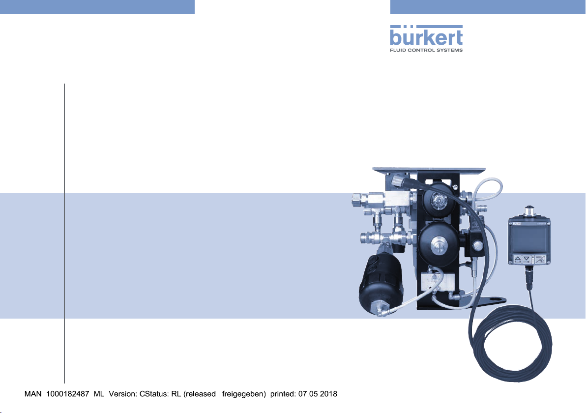
Type 8821
Functional unit comprising MasterJet air unit and base construction
Funktionseinheit bestehend aus MasterJet mit Lufteinheit und Sockelaufbau
Unité fonctionnelle comprenant le MasterJet avec unité pneumatique et socle
Page 2
We reserve the right to make technical changes without notice.
Technische Änderungen vorbehalten.
Sous réserve de modifications techniques.
© Bürker t Werke GmbH & Co. KG, 2012 - 2017
Operating Instructions 1805/01_EU-EN_00810012 / Original DE
Page 3
Type 8821
english
Contents
OPERATING INSTRUCTIONS ..................................................................5
1.
1.1. Symbols ..........................................................................................5
1.2. Definitions of terms .....................................................................5
2. AUTHORIZED USE........................................................................................6
2.1. Restrictions ....................................................................................6
3. BASIC SAFETY INSTRUCTIONS ...........................................................6
4. GENERAL INFORMATION ..........................................................................7
4.1. Contact address ...........................................................................7
4.2. Warranty..........................................................................................7
4.3. Information on the Internet ..........................................................7
5. SYSTEM DESCRIPTION .............................................................................8
5.1. Intended application area............................................................8
5.2. General description ...................................................................... 8
5.3. Functions ........................................................................................8
6. TECHNICAL DATA ..........................................................................................9
6.1. Conformity ...................................................................................... 9
6.2. Standards ....................................................................................... 9
6.3. Operating conditions ...................................................................9
6.4. General technical data ................................................................9
6.5. Schematic circuit ........................................................................12
7. ASSEMBLY
7.1. Safety instructions ......................................................................13
7.2. Assembly of the functional unit ................................................13
..................................................................................................... 13
8. INSTALLATION
8.1. Safety instructions ......................................................................15
8.2. Pneumatic installation ................................................................15
8.3. Hydraulic installation ..................................................................16
8.4. Parts list for the screw connections .......................................16
8.5. Overview of MasterJet screw connections
with the pneumatic unit .............................................................17
8.6. Electrical installation ...................................................................18
8.7. Electrical installation ...................................................................19
9. START-UP
9.1. Safety instructions ......................................................................20
9.2. Starting-up the pneumatic unit ................................................20
9.3. Starting-up Type 8821 ..............................................................21
10. OPERATION
10.1. Safety instructions ......................................................................22
10.2. Manual operation of the MasterJet .........................................23
10.3. Automatic operation of the MasterJet ....................................23
10.4. Sensor programming .................................................................24
11. MAINTENANCE
11.1. Safety instructions ......................................................................26
12. SPARE PARTS .............................................................................................. 27
.............................................................................................15
.......................................................................................................20
................................................................................................... 22
............................................................................................ 26
3
Page 4

13. REPAIRS .......................................................................................................... 28
english
13.1. Replacing pilot valve Type 6014 .............................................28
13.2. Replacing pilot valve Type 0450 .............................................29
13.3. Replacing flow-rate sensor SE12 ...........................................30
13.4. Replacing the display and evaluation unit
(electronics module SE32) .......................................................31
13.5. Replacing drive DM63 and DM50 ..........................................32
13.6. Replacing expansion cylinder DM63 .....................................33
13.7. Replacing the pneumatic unit ..................................................34
14. SHUTDOWN...................................................................................................35
14.1. Safety instructions ......................................................................35
14.2. Disassembly of Type 8821 .......................................................35
15. TRANSPORTATION, STORAGE, DISPOSAL .................................36
Type 8821
4
Page 5
Type 8821
english
Operating Instructions
1. OPERATING INSTRUCTIONS
The operating instructions describe the entire life cycle of the device.
Keep these instructions in a location which is easily accessible to
every user, and make these instructions available to every new owner
of the device.
The operating instructions contain important safety
information!
Failure to observe these instructions may result in hazardous
situations.
• The operating instructions must be read and understood.
1.1. Symbols
DANGER!
Warns of an immediate danger!
• Failure to observe the warning will result in a fatal or serious
injury.
WARNING!
Warns of a potentially dangerous situation!
• Failure to observe the warning may result in serious injuries or
death.
CAUTION!
Warns of a possible danger!
• Failure to observe this warning may result in a moderate or
minor injury.
NOTE!
Warns of damage to property!
• Failure to observe the warning may result in damage to the
device or the equipment.
Indicates important additional information, tips and
recommendations.
Refers to information in these operating instructions or in
other documentation.
→ Designates a procedure which you must carry out.
1.2. Definitions of terms
In these instructions, the maximized version of the term "functional
unit" comprises the following components:
MasterJet, pneumatic unit and base construction.
While the minimum version only comprises
the pneumatic unit and base construction.
5
Page 6
Type 8821
english
Authorized Use
2. AUTHORIZED USE
Non-authorized use of the functional unit may be dangerous
to people, nearby equipment, and the environment.
• The functional unit is designed to control and monitor the cooling circuits on industrial production systems.
• The functional unit must not be used in potentially explosive
areas.
• Use according to the authorized data, operating conditions, and
conditions of use specified in the contract documents and operating instructions. These are described in the chapter entitled
"Technical Data".
• The functional unit must only be used in conjunction with thirdparty devices and components recommended and approved by
Bürkert.
• Correct transportation, storage, and installation, as well as careful use and maintenance are essential for reliable and faultless
operation.
• Do not make any external modifications to the device housings.
Do not paint housing parts or screws.
• Only use the functional unit as intended.
2.1. Restrictions
If exporting the system/device, observe any existing restrictions.
3. BASIC SAFETY INSTRUCTIONS
These safety instructions do not make allowance for any
• Contingencies and events which may arise during the installation,
operation, and maintenance of the devices.
• Local safety regulations – the operator is responsible for observing
these regulations, also in relation to the installation personnel.
Danger – high pressure!
• Turn off the pressure and vent the lines before loosening lines
or valves.
Risk of electric shock!
• Switch off the power supply and secure it against reactivation
before reaching into the device or equipment!
• Observe applicable accident prevention and safety regulations
for electrical equipment!
General hazardous situations!
To prevent injuries:
• Do not supply the medium connectors of the system with
aggressive or flammable media.
• Do not supply the compressed-air connections with any liquids.
• The impact protection on the top of the device must not be
loaded with more than 70 kg.
• Ensure that the system cannot be activated unintentionally.
6
Page 7
Type 8821
english
General Information
• Installation and repair work may be carried out by authorized
technicians only and with the appropriate tools.
• After an interruption in the electrical or pneumatic supply,
ensure that the process is restarted in a defined or controlled
manner.
• The device must only be operated when in a perfect condition
and in consideration of the operating instructions.
• The general rules of technology apply to application planning
and operation of the device.
NOTE!
Electrostatic sensitive components/modules!
The device contains electronic components which react sensitively
to electrostatic discharge (ESD). Contact with electrostatically
charged persons or objects are hazardous to these components.
In the worst case scenario, they will be destroyed immediately or
will fail after start-up.
• Observe the requirements in accordance with EN 61340-5-1
and -5-2 to minimize/avoid the possibility of damage caused by
a sudden electrostatic discharge!
• Also, ensure that you do not touch electronic components when
the power supply voltage is present!
4. GENERAL INFORMATION
4.1. Contact address
Germany
Bürkert Fluid Control Systems
Technik Center
Christian-Bürkert-Str. 13-17
D-74653 Ingelfingen
Germany
Tel. + 49 (0) 7940 - 10 91 110
Fax + 49 (0) 7940 - 10 91 448
E-mail: info@de.buerkert.com
International
Contact addresses can be found on the final pages of the printed
operating instructions.
And also on the Internet at:
www.burkert.com
4.2. Warranty
The warranty is only valid if the functional unit is used as intended in
accordance with the specified application conditions.
4.3. Information on the Internet
The operating instructions and data sheets for Type 8821 can be found
on the Internet at:
www.burkert.com
7
Page 8
Type 8821
english
System Description
5. SYSTEM DESCRIPTION
5.1. Intended application area
Type 8821 is intended for the use in industrial systems, especially
robot applications used for resistance spot welding for controlling
and monitoring cooling water circuits.
5.2. General description
Type 8821 is used to control and monitor the flow of coolant in
industrial robot applications used for resistance spot welding.
The coolant circuit is controlled by the unit and the required coolant
quantity is monitored.
Additionally, the water pressure within the system is reduced when
the flow of cooling water is switched off.
This is advantageous when replacing the welding electrodes as this
prevents any cooling water from escaping.
5.3. Functions
• The main valve (NC) for the feed and return of the cooling circuit is
controlled via pilot valve Type 6014.
• During shutdown, the pressure in the cooling system is automatically
reduced by the delayed drive control in the return.
• The residual pressure is released via delayed switched pilot valve
Type 0450 and pneumatic expansion cylinder DM63 in the closed
cooling circuit.
• An optical cooling water flow sensor Type 8012 DN8, comprising
evaluation electronics with integrated impeller SE12, fitting SO30
and electronics module SE32 monitors the flow rate and sends
signal outputs to the overriding control or robot in accordance with
the programmed monitoring windows.
• The flow-rate sensor comprises a flow direction detector.
• The flow quantity of the cooling water can be limited via a manual
adjusting screw on the pneumatic feed drive.
8
Page 9
Type 8821
english
Technical Data
6. TECHNICAL DATA
6.1. Conformity
Type 8821 conforms with the EC Directives according to the EC
Declaration of Conformity.
6.2. Standards
The applied standards, which verify conformity with the EC Directives, can be found on the EC-Type Examination Certificate and / or
the EC Declaration of Conformity.
6.3. Operating conditions
WARNING!
Risk of injury!
Malfunction if used outside!
• Do not use Type 8821 outdoors and avoid heat sources which
may cause the permissible temperature range to be exceeded.
Permitted temperatures
Ambient temperature: +5 to +55°C
Medium temperature: +5 to +90°C
Media: Aggressive and neutral fluids
Protection class: IP65 in accordance with EN 60529
6.4. General technical data
Weight: 9.5 kg
Housing material: VA / brass
External sealing material: EPDM
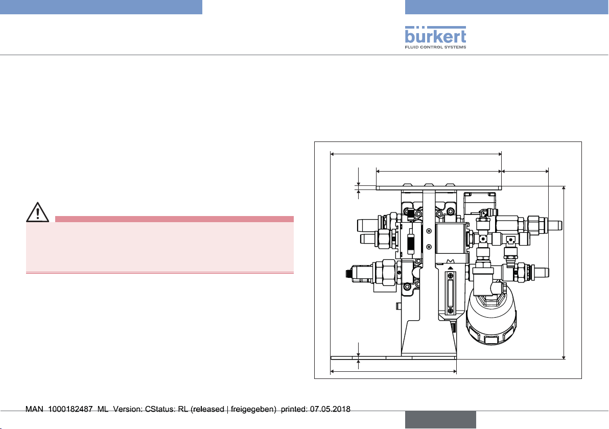
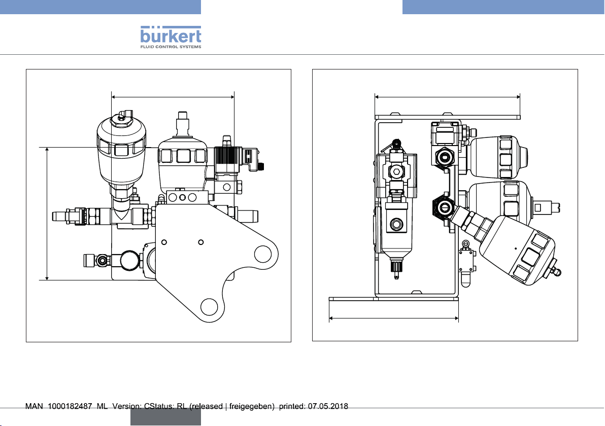
6.4.1. Dimensions
271,3
199,5
6
5
199,8
85,6
276,3
Fig. 1: Type 8821, MasterJet with pneumatic unit and base construction;
rear view
9
Page 10
Type 8821
english
Technical Data
199,5
216,1
Fig. 2: Type 8821, MasterJet with pneumatic unit and base construction;
bottom view
216
192,6
Fig. 3: Type 8821, MasterJet with pneumatic unit and base construction;
left side view
10
Page 11
Type 8821
english
Technical Data
6.4.2. Pneumatic data
Control medium: Quality classes in accordance with DIN ISO 8573-1
Dust content: Class 5: max. particle size 40 μm,
max. particle density 10 mg/m
3
Water content: Class 3: max. pressure dew point -20°C or
min. 10°C below the lowest
operating temperature
Oil content: Class 5: max. 25 mg/m
3
Temperature range
of compressed air: -10 to +50°C
Pressure range 3.0 to 9.5 bar
Air flow rate IN/min
(for aeration and deaeration) (QNn value according to definition for
pressure drop from 7 to 6 bar absolute)
Connections Plug-in hose connector
Ø 6 mm / 1/4"
6.4.3. Hydraulic data
Medium: Water, cooling water
Max. operating pressure: 9.5 bar
Ambient temperature: +5 to +55°C
Water connections
on the block: See “Fig. 7”, page 17
6.4.4. Electrical data
Valve
Connection: DIN 43650 form B with M12 adapter
Power supply: 24 V DC
Sensor:
Connection: M12 connector
Power supply: 12 - 30 V DC
Measuring precision: +/- 1% of the final value, 3% of the mea-
sured value at a flow rate of 0.3 to 10 m/s
Output: 1 impulse /revolution, transistor NPN
700 mA
11
Page 12
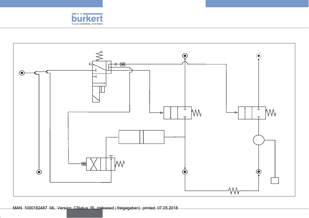
6.5. Schematic circuit
english
Type 8821
Technical Data
P customer's pressure
installation
P 5-10 bar
Pneumatic
leading to
the robot
3
1
3/2-way valve
(6014) 24VDC
ø 0.05
5/2-way valve (0450)
pneumatically controlled
Connector
4
3 1
Supply line
Customer's
supply
Return travel
ø 0.5
2
Valve supply 1
(2031) DN15
Valve return 2
(2031) DN15
ø 0.5
Deaeration
Air
Water
Flow-rate sensor
SE12 DN08
2
Supply line
Spot-welding gun
Return travel
Display SE32
Fig. 4: Schematic circuit
12
Page 13
Type 8821
english
Assembly
7. ASSEMBLY
7.1. Safety instructions
DANGER!
Risk of injury from high pressure in the system!
• Turn off the pressure and vent the lines before loosening lines
or valves.
Risk of injury due to electrical shock!
• Switch off the power supply and secure it against reactivation
before reaching into the device or equipment!
• Observe applicable accident prevention and safety regulations
for electrical equipment!
WARNING!
Risk of injury from improper assembly!
• Installation must only be carried out by authorized technicians
and with the appropriate tools!
Risk of injury from unintentional activation of the system and
uncontrolled restart!
• Secure system from unintentional activation.
• Following assembly, ensure a controlled restart.
7.2. Assembly of the functional unit
WARNING!
Risk of injury from a sudden discharge of cooling water due
to improper installation!
If the installation position is incorrect (horizontal orientation or
upside down), the discharge function of the expansion cylinder is
no longer guaranteed. This can cause cooling water to suddenly
escape from the spot-welding gun when the electrode caps are
being replaced.
• Only install the functional unit vertically.
• The installation position must be observed.
Procedure:
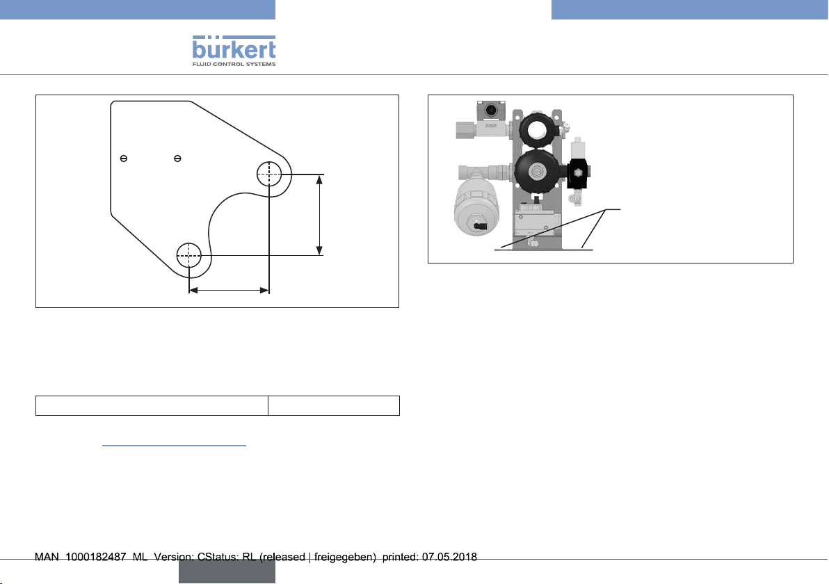
→ Connect the MasterJet to a base plate or fixture using the desig-
nated bores (see “Fig. 5” and “Fig. 6”).
NOTE!
• Pay attention to the installation position of the functional unit. If
installed correctly, the impact protection plate is at the top!
13
Page 14
Type 8821
english
Assembly
88
88
Fig. 5: Screwing bores in the base plate
A fixture that matches the screw hole pattern on the robot can be
supplied for mounting on the base of the robot.
Item designation and order number:
Angled bracket, complete 771338
See section “12. Spare Parts”, page 27
14
Fixture for installation of
the base of the robot
Fig. 6: MasterJet including fixture for mounting on the base of the robot
7.2.1. Mounting options:
Generally, various options are available for mounting the MasterJet.
Recommendation:
Mount the unit as close as possible to the process (e.g. spot-welding
gun).
Long hose lengths are required with large distances. This has the following consequences:
• The amount of coolant increases, which means that a correspondingly larger expansion cylinder has to be selected.
• Delayed reaction times when it comes to changes in the flow rate
caused, for example, by an electrode cap breaking on the spotwelding gun.
The detection of these and other error conditions are therefore
also delayed.
Page 15
Type 8821
english
Installation
8. INSTALLATION
8.1. Safety instructions
DANGER!
Risk of injury from high pressure in the system!
• Turn off the pressure and vent the lines before loosening lines
or valves.
Risk of injury due to electrical shock!
• Switch off the power supply and secure it against reactivation
before reaching into the device or equipment!
• Observe applicable accident prevention and safety regulations
for electrical equipment!
WARNING!
Risk of injury from improper installation!
• Installation may be carried out by authorized technicians only
and with the appropriate tools!
Risk of injury from unintentional activation of the system and
uncontrolled restart!
• Secure system from unintentional activation.
• Following installation, ensure a controlled restart.
8.2. Pneumatic installation
DANGER!
Risk of injury from high pressure in the system!
• Turn off the pressure and vent the lines before loosening lines
or valves.
Procedure:
→ Following the mechanical mounting of the MasterJet, establish
a pneumatic connection between the pneumatic unit and
MasterJet:
→ Connect the factory-provided air supply to the pneumatic unit.
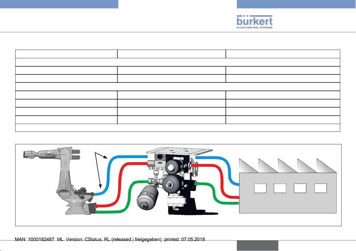
See “Fig. 7: Overview of the hose system Type 8821”
Observe the air volume requirements in the robot
application.
The MasterJet requires a plug-in hose connection with a
6 mm diameter. The robot application requires a 1/2" connection (1/2" on M22 x 1.5 or equivalent is standard in most
structural work applications).
→ Connect the connecting hose leading to the base of the robot or
stationary welding gun to the output side of the T-fitting on the
maintenance unit.
→ Tighten the screws.
15
Page 16
Type 8821
english
Installation
NOTE!
Damage caused by high inlet pressure!
• The air pressure provided on site must not exceed the maximum
permissible pressure on the functional unit.
• Use a suitable pressure reducer if the inlet pressure is higher
than permissible!
8.3. Hydraulic installation
NOTE!
Damage caused by improper tightening of the screws!
• When tightening the universal rotary joint observe the maximum
torque or the 1/4 revolution tightening otherwise the screw connection can tear.
Procedure:
→ Connect the warehouse cooling water supply and return on the
input side of the MasterJet using the screws provided.
NOTE!
Malfunction of the MasterJet due to the supply and return
being mixed up!
The existing water flow is not measured if the flow direction is
mixed up.
• Observe the flow direction when connecting the cooling water
supply.
→ Cut the supplied plug-in hoses to length in accordance with the
distance between the MasterJet output and the connection point
on the base of the robot.
Cut the hoses to such a length that they can be laid with
large bending radii. Bending radii that are too tight can hinder
the water flow.
→ Then connect the prepared houses to the output side of the
MasterJet and the base of the robot.
Match the color of the hose with the color-coded connections
on the base of the robot: supply = green; return = red.
8.4. Parts list for the screw connections
Position Material number Quantity
1. GE15LREDOMDCF 1
2. 3C382-15-8 1
3. EVGE22LR3/4KEGMS 1
4. GE22LR3/4KEGMSX 1
5. 3D082-22-12B 1
6. 3C382-22-12B 1
7. EVGE15LR1/2KEGMS 1
8. GE15LR1/2KEGMSX 1
9. 3D082-15-8B 1(2)
10. 3C382-15-8B 1
11. 35C82-15-8B (2)
12. H898202 (1)
Tab. 1: Parts list for the screw connections
16
Page 17
Type 8821
english
Installation
8.5. Overview of MasterJet screw connections with the pneumatic unit
On the base of the robot On the functional unit/output On the functional unit/input
Pneumatic connections
Universal sealing head H898202 *) Double nipple GE15LREDOMDCF
35C82-15-8B + universal sealing head 3C382-15-8
Cooling water connections
Universal sealing head 35C82-15-8B *) Supply double nipple EVGE15LR1/2KEGMS Return double nipple EVGE22LR3/4KEGMS
+ hose coupling 3D082-15-8B + hose coupling 3D082-22-12B
Universal sealing head 3D082-15-8B *) Return double nipple GE15LR1/2KEGMSX Supply double nipple GE22LR3/4KEGMSX
+ universal sealing head 3C382-15-8B + universal sealing head 3C382-22-12B
*) included in the equipment pack
Tab. 2: Overview of the screw connections
Bending radius
When laying
the hoses,
ensure there
are sufficient
bending radii!
Fig. 7: Overview of the hose system Type 8821
17
Page 18
Type 8821
english
Installation
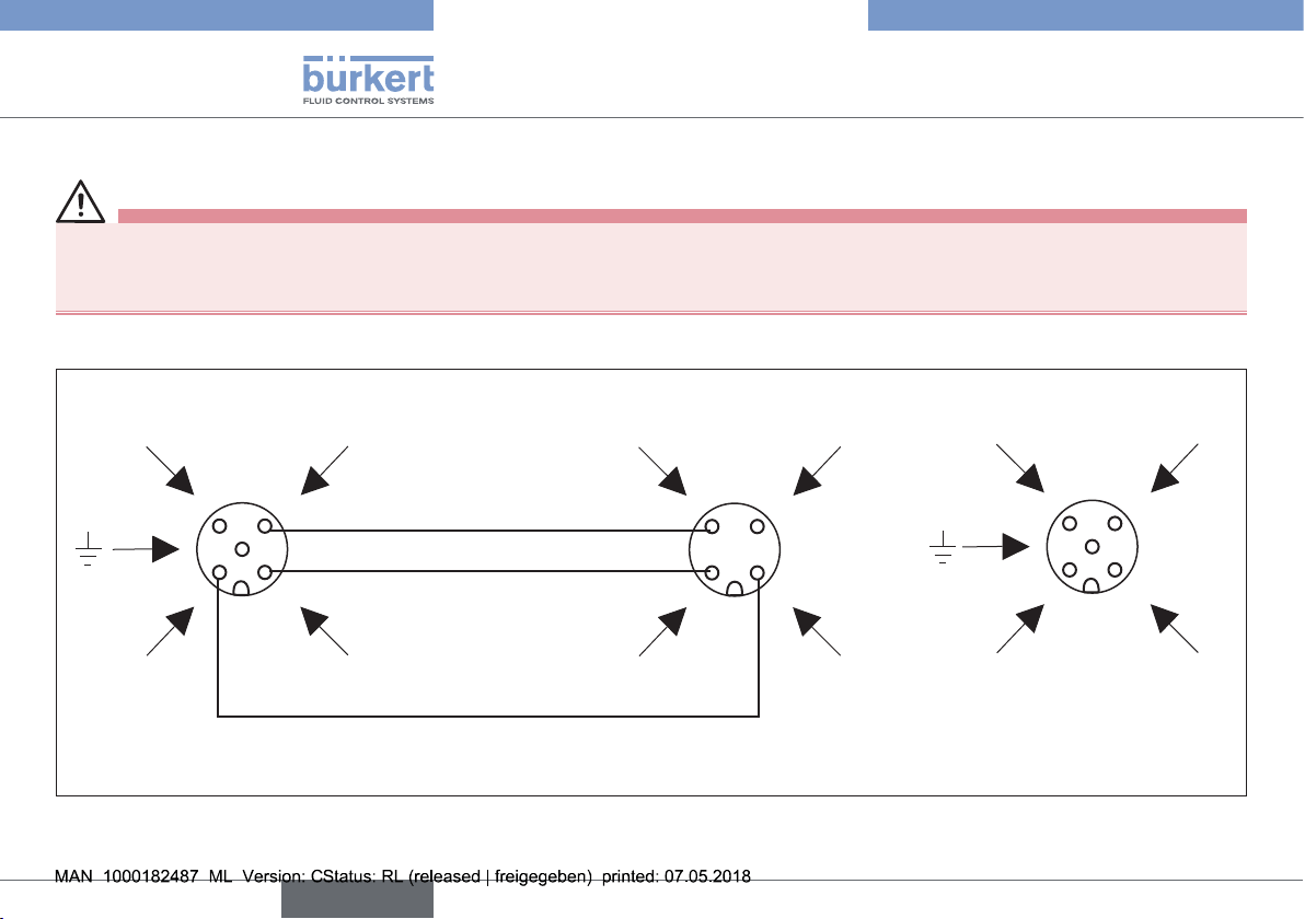
8.6. Electrical installation
DANGER!
Risk of injury due to electrical shock!
• Switch off the power supply and secure it against reactivation before reaching into the device or equipment!
• Observe applicable accident prevention and safety regulations for electrical equipment!
Overview: Electrical plug configuration
SE12
Not used
4
5
1
V+ (12-36 VDC)
Connection of the 5-pole M12 plastic
device plug
Fig. 8: Electrical connection; overview of the plugs
18
0 V DC
3
Max. cable length 10 m
2
Impulse output
(default NPN)
SE32
0 V DC
3
2
Impulse input
(default NPN)
Connection of the 4-pole
M12 metal plug
Not used
4
1
V+ (sensor)
PNP transistor
output
4
5
1
V+ (12-36 V DC)
Connection of the 5-pole plastic
device plug
3
2
NPN transistor
output
0 V DC
Page 19
Type 8821
english
Installation
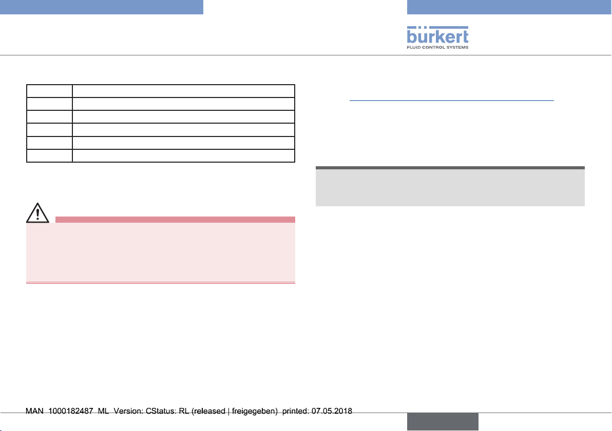
Classification of wire colors:
Pin Wire color
1 brown
2 white
3 blue
4 black
5 gray
Tab. 3: Electrical connection; wire colors
8.7. Electrical installation
DANGER!
Risk of injury due to electrical shock!
• Switch off the power supply and secure it against reactivation
before reaching into the device or equipment!
• Observe applicable accident prevention and safety regulations
for electrical equipment!
Procedure:
→ Connect the flow-rate sensor SE12 DN08 with the display and
evaluation unit (electronics module SE32) via the connection
cable (ID number 555676). To do so, unscrew the standard M12
plug pin including the screw lock.
The display and evaluation unit (electronics module SE32) can
be mechanically mounted anywhere along the length of the connection cable (e.g. on the safety fence).
→ Connect the supply voltage for the display and evaluation unit
(electronics module SE32) to the 5-pole M12 device plug pin
(see “Fig. 8: Electrical connection; overview of the plugs”).
→ In the event of an alarm, etc., the unit's evaluation signals on the
same plug pin can be transferred to the overriding control or the
robot via the corresponding cable (see connection diagram with
NPN and PNP output).
NOTE!
Observe the maximum load capacity on the outputs!
• Failure to do so can overload the device and damage the
electronics.
19
Page 20
Type 8821
english
Start-Up
9. START-UP
9.1. Safety instructions
WARNING!
Risk of injury from improper operation!
Improper operation may result in injuries as well as damage to the
device and the surrounding area.
• Before start-up, ensure that the operating personnel are familiar
with and completely understand the contents of the operating
instructions.
• Observe the safety instructions and intended use.
• Only adequately trained personnel may start up the equipment/
the device.
9.2. Starting-up the pneumatic unit
To test the MasterJet, the pneumatic unit must first be placed into
operation as the control valve and expansion cylinder of the MasterJet
are controlled by compressed air.
DANGER!
Risk of injury from moving compressed air hoses that are not
connected!
• Check all of the hose connections are secured tightly before
charging the pneumatic unit with compressed air.
• Ensure that the exhaust shut-off valve remains closed during
initial start-up.
Procedure:
→ Open the air supply line on the input side of the pneumatic unit.
→ Check the compressed air connections and resolve any existing
air leaks with suitable measures.
→ Open the exhaust shut-off valve if there are no existing air leaks.
→ Also check the compressed air connections and components of
the pneumatic unit for leaks.
→ Ensure that there are no leaks.
→ Then check the electric feedback from the pressure switch.
→ Check that the input on the connected PLC or robot control is
set to the logic "1" switching status.
Observe the correct supply pressure on the input of the
pneumatic unit. It should be between 3 and 6 bar.
→ After deactivating the exhaust shut-off valve, the electric input of
the connected PLC or robot control should change to the logic
"0" switching status.
Start-up of the pneumatic unit is then complete.
20
Page 21
Type 8821
english
Start-Up
9.3. Starting-up Type 8821
Once
• the connected line system has been charged with compressed air
and cooling water and
• the pneumatic unit has been placed into operation,
• the functional unit can be started up.
Procedure:
→ After opening the cooling water flow, check the line feed on the
input side of the MasterJet for leaks.
→ Repair any leaks on the hose connections of the cooling water
circuit.
→ Start the cooling circuit via manual valve actuation on pilot
valve 6014 (see “Fig. 9”).
→ Check the screws on the output side for leaks.
→ A red LED indicates if the preset limit has been exceeded.
→ If all of the conditions are correct, the current flow rate is shown
on the display of the evaluation unit (electronics module SE32)
in liters or gallons per minute, depending on the settings when
the cooling water is running.
→ The maximum flow rate can be reduced to the required value
using the setting screw on the return valve of the MasterJet by
opening the lock nut and then turning the flat-blade screw.
NOTE!
Suitable tools for setting the flow rate:
• To reduce the flow rate, the setting screw can be slightly
adjusted with a large hexagon screwdriver. Counter this with an
open-end wrench.
→ Set the limit values for the flow rate monitor in the programming
menu of the evaluation unit (electronics module SE32)
(see “10.4.1. Programming menu of the evaluation unit (electronics module SE32)”).
The settings for other parameters, switching process, and measuring units are provided in the operating instructions for the
electronics module SE32.
→ To check the electrical functions, deactivate the cooling circuit
via the manual valve actuator on pilot valve 6014 (see “Fig. 9”).
→ To check the electrical functions, first of all set the corre-
sponding switching output of the PLC or robot control to the
logic "1" switching status.
Pilot valve 6014 is controlled with switching command "1" that
pneumatically opens the supply and return valves of the MasterJet and establishes the cooling circuit.
At the same time, the pneumatic side in the expansion cylinder
is pressed forward by means of a cover plate in the pneumatic
control circuit of the switching valve. The water in the expansion
cylinder is pressed into the cooling circuit.
→ Then reset the switching status of the switch output.
21
Page 22
Type 8821
english
Operation
This closes the cooling circuit and the air chamber in the
expansion cylinder is vented after a time delay.
The remaining pressure in the cooling circuit for the spotwelding gun is released into the expansion cylinder.
WARNING!
Risk of injury from ejected cooling water or steam!
If the expansion cylinder malfunctions when the electrode cap is
removed, this can cause cooling water or steam to escape.
• Only remove the electrode caps using the intended tools.
• Wear protective glasses and clothing when removing the electrode caps.
→ Remove the electrode caps from the spot-welding gun to test
the functionality of the MasterJet.
If the MasterJet is operating correctly, water must not spray out
of the electrode shaft when pressure is applied.
Start-up is completed following the function test of the expansion
cylinder.
10. OPERATION
10.1. Safety instructions
WARNING!
Danger due to improper operation!
Improper operation may result in injuries as well as damage to the
device and the area around it.
• The operating personnel must know and have understood the
contents of the operating instructions.
• Observe the safety instructions and intended use.
• Only adequately trained personnel may operate the equipment/
the device.
22
Page 23
Type 8821
english
Operation
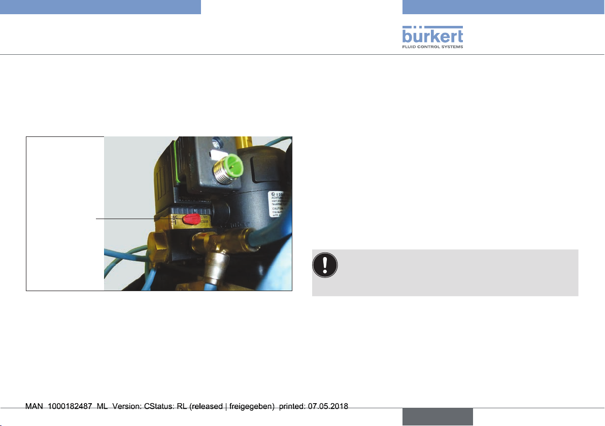
10.2. Manual operation of the MasterJet
There are two ways to activate the cooling circuit:
• Either connect pilot valve Type 6014 with +24 VDC or
• Move the manual lever on the valve
(90° clockwise).
Manual lever
Fig. 9: Pilot valve Type 6014 with a lever for manual valve activation
Manual operation is used when starting up the system so that the
parameters for the flow monitor can be set for the first time, and to
ensure that the current flow rate is monitored simultaneously.
The correct functionality of the expansion cylinder can be checked via
a manual activation lever on pilot valve Type 0450.
10.3. Automatic operation of the
MasterJet
To activate the cooling circuit, the coil of pilot valve Type 6014 is
switched via a 24 V DC output of a PLC or robot control, which pneumatically activates the drives in the supply and return of the cooling
circuit, thus activating the cooling circuit.
At the same time as activating the cooling circuit, expansion cylinder
DM63 is pneumatically activated with a delay via pilot valve Type 0450
and a cover plate in the control circuit. When activated, the expansion
cylinder that is built into the supply line of the cooling water circuit
presses the cooling water in the cylinder into the cooling circuit.
If the cooling circuit is closed by the control (control of the 24 V DC
output on pilot valve Type 6014), the activation of the expansion cylinder
is also switched off via its pilot valve Type 0450. The existing water
pressure is dispelled in the expansion cylinder.
The dimensions of the expansion cylinder are dependent
on the length and diameter of the cooling circuit hoses. The
standard design is preferentially used with the MasterJet on
the base of the robot.
When the cooling circuit is activated, cooling water passes through
the flow-rate sensor SE12 located in the return.
Depending on the flow rate, the flow-rate sensor SE12 sends impulses
to the display and evaluation unit (electronics module SE32).
Based on the incoming impulses, the evaluation unit calculates the
flow rate and compares this with the minimum and maximum values
specified by the user.
23
Page 24
Type 8821
english
Operation
Following a programmable fade-out time, during which the current high
flow values are ignored until they are stabilized, an output is set on
the PLC or robot control when the correct flow rate is achieved. This
output is only reset in the event of a malfunction.
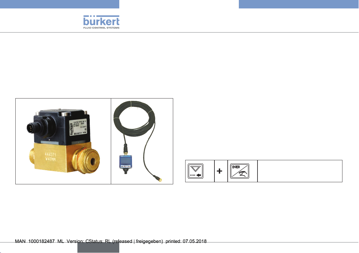
10.4. Sensor programming
Flow-rate sensor SE12 is connected to the display and evaluation
unit (electronics module SE32) by means of a connection cable.
Fig. 10: Flow-rate sensor including connection cable and evaluation unit
(electronics module SE32)
The maximum length of the connection cable is 10 m.
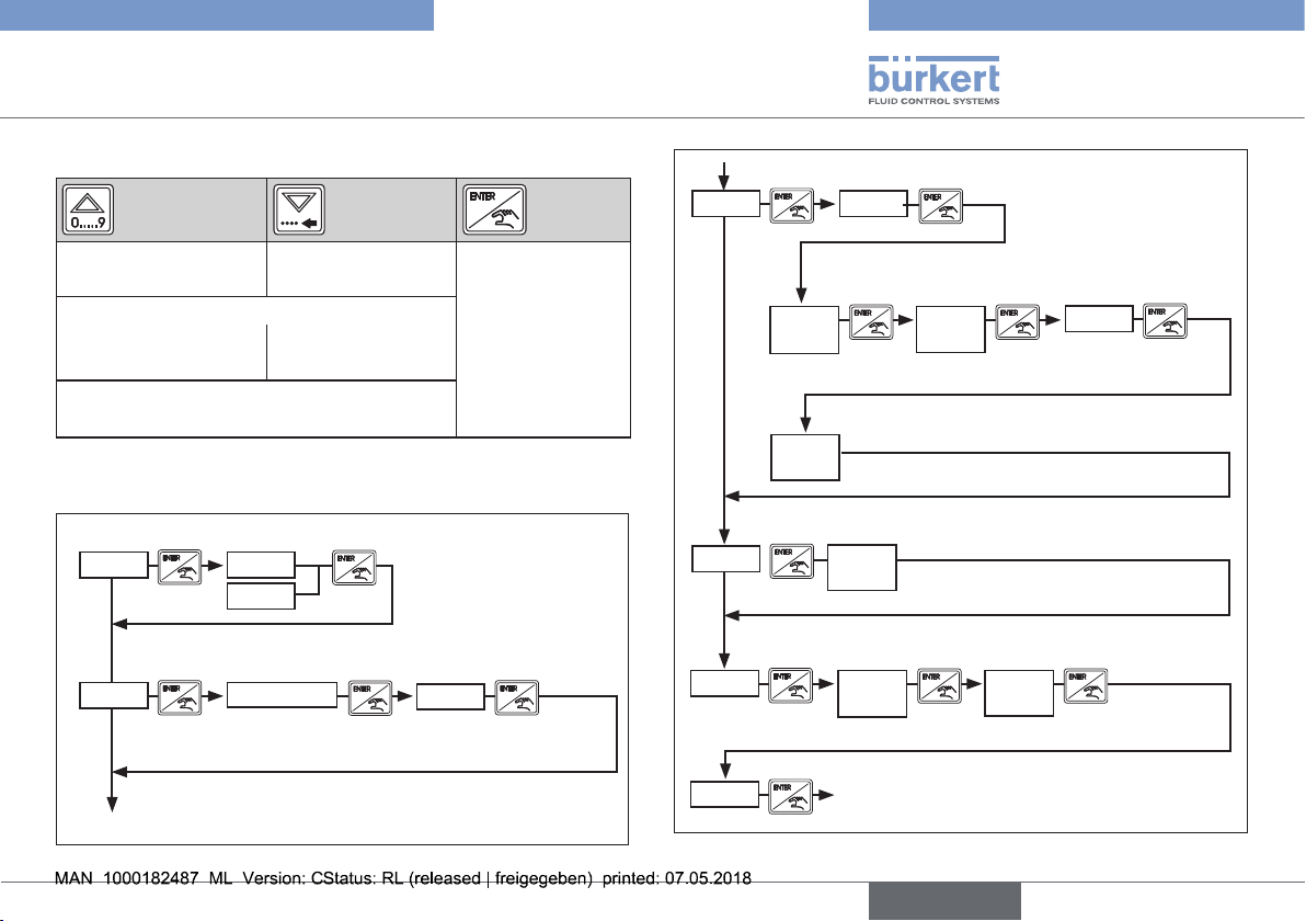
10.4.1. Programming menu of the evaluation
unit (electronics module SE32)
The following parameters can be set in this menu:
• Quantity unit: Liter/second or liter/minute.
• K-factor for the flow-rate sensor: Number of impulses per liter:
• Output action (MODE): Specification of the lower and upper limit
of the limit switch and the switching delay time.
• Filter effect: Adjustable range from 0 to 9.
• Bar graph scaling: Specification of the lower and upper limit.
Accessing the programming menu:
When the operating voltage is applied, the evaluation unit (electronics
module SE32) is in the read level. Switch to the calibration level for
programming purposes.
Changing to the calibration level:
Press and hold both of the
buttons simultaneously for approx.
5 seconds.
24
Page 25
Type 8821
english
Operation
Function of the buttons in the calibration level:
Switches to the previous menu option
Enter values
Increase value
Press both of the buttons simultaneously to
move the decimal point.
Switches to the next
menu option
Change by one
position to the left
• Confirm menu
option
• Take over
settings
• Change to the
read level
Tab. 1: Function of the buttons in the calibration level
Menu structure:
Specify the measurement unit
UNIT
L/S
L/M
Set the K-factor for the flow-rate sensor
K-FAC
NO TEACH
144
Enter
value (144)
Set the output action (MODE)
OUT
MODE
Enter switching threshold
7500
OLO
Lower limit
Enter switching delay
00
Measurement unit in seconds
DEL
Set the filter
FILT
5
FILT
Scale the bar graph
BRGR
0.600
BGLO
Lower limit
8500
OHI
Upper limit
Setting value 0 to 9
12.00
BGHI
Upper limit
INV
Inversion
YES / NO
OUT
END
Fig. 11: Menu structure; programming SE32
Return to the read level
25
Page 26
Type 8821
english
Maintenance
Further information on operating and programming the display and
evaluation unit (electronics module SE32) is included in the operating
instructions.
11. MAINTENANCE
11.1. Safety instructions
DANGER!
Risk of injury from high pressure in the system!
• Turn off the pressure and vent the lines before loosening lines
or valves.
Risk of injury due to electrical shock!
• Switch off the power supply and secure it against reactivation
before reaching into the device or equipment!
• Observe applicable accident prevention and safety regulations
for electrical equipment!
WARNING!
Risk of injury from improper maintenance!
• Maintenance may be carried out by authorized technicians only
and with the appropriate tools!
Risk of injury from unintentional activation of the system and
uncontrolled restart!
• Secure system from unintentional activation.
• Following maintenance, ensure a controlled restart.
26
Page 27
Type 8821
english
Spare Parts
12. SPARE PARTS
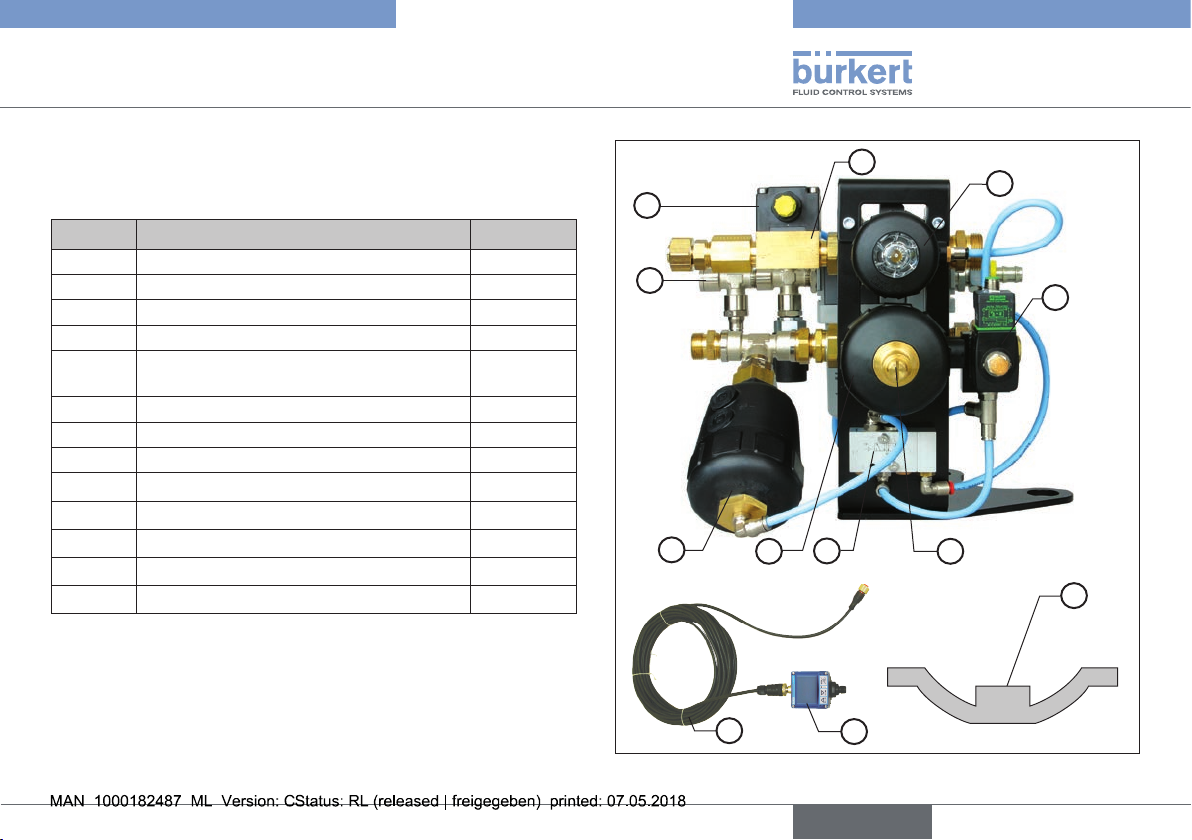
Order numbers for spare parts:
Position Part designation Order no.
1 Sensor SE12 558777
2 Fitting DN08 444571
3 Electronics module SE32 563940
4 Pilot valve 6014 153771
5
6 Expansion cylinder 211861
7 Pilot valve release Type 0450 904258
8 Drive WWA/DM50 246737
9 Drive WWA/DM63 246738
10 Max stroke limit 637866
11 M12 4-pole plug (not pictured) 448856
12 Complete pneumatic unit, right 904230
13 Diaphragm 677664
Tab. 4: Overview of spare parts
Cable for the sensor / electronics
module SE32
555676
1
12
2
8
4
6
9
7
5
3
10
13
Fig. 12: Overview of spare parts
27
Page 28
Type 8821
english
Repairs
13. REPAIRS
13.1. Replacing pilot valve Type 6014
DANGER!
Risk of injury from high pressure in the system!
• Turn off the pressure and vent the lines before loosening lines
or valves.
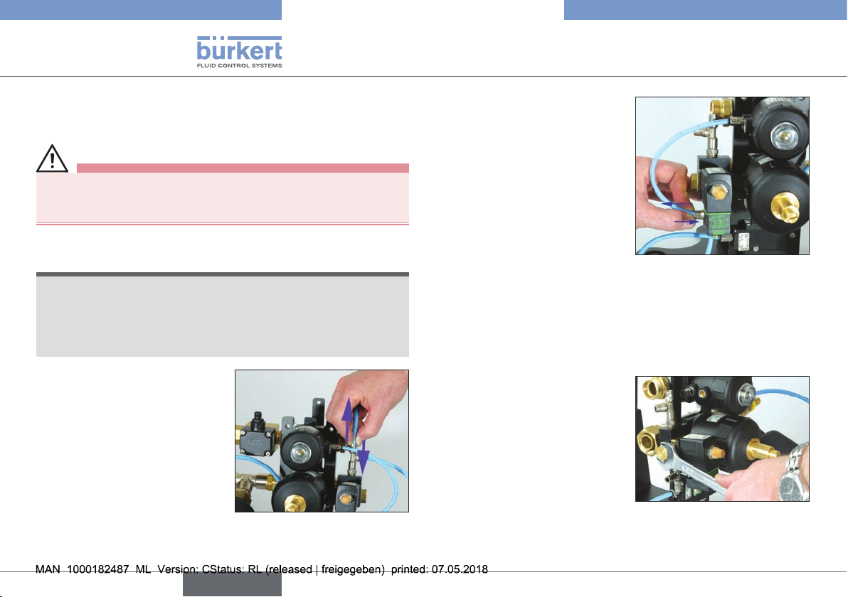
Removing the pilot valve:
NOTE!
Malfunction caused by mixing up the plug-in hose
connections
• Before disconnecting the plug-in hoses identify the affiliation of
the hose and connection, to prevent the connections from being
mixed up when being reconnected.
Before replacing the pilot valve,
disconnect the pneumatic supply
as described below.
→ Push back the lock ring on the
plug-in connector and simultaneously pull the plug-in hose
from the plug-in connector.
Fig. 13: Replacing pilot valve
Type 6014
→ Loosen and remove all of the
other plug-in hose connectors
in the same way.
Fig. 14: Removing the plug-in
hoses
Once all of the plug-in hose connections have been removed:
→ Unscrew the plug pin for the electrical M12 control from the
valve coil.
Then remove the pilot valve Type 6014 as described below.
→ Loosen and remove the
through bolt using a suitable
flat or box wrench.
→ Remove the valve.
Fig. 15: Removing pilot valve
Type 6014
28
Page 29
Type 8821
english
Repairs
Installation of the new pilot valve:
→ Attach the valve.
→ Caution!
Replace the O-ring before pushing the through bolt through.
→ Insert the through bolt and tighten to a torque of 1 Nm using a
flat or box wrench.
The torque must be observed!
The valve housing may be damaged if the bolt is tightened
excessively.
→ Reestablish all of the plug-in hose connections. Ensure that the
hose and connector are assigned correctly.
→ Connect the plug pin for the electrical M12 control to the valve
coil.
13.2. Replacing pilot valve Type 0450
DANGER!
Risk of injury from high pressure in the system!
• Turn off the pressure and vent the lines before loosening lines
or valves.
Dismantling pilot valve Type 0450:
→ Loosen and remove both of
the fastening screws on the
fixing bracket using a flatblade screwdriver.
Fig. 16: Removing pilot valve
Type 0450
NOTE!
Malfunction caused by mixing up the plug-in hose
connections
• Before disconnecting the plug-in hoses identify the affiliation of
the hose and connection, to prevent the connections from being
mixed up when being reconnected.
29
Page 30
Type 8821
english
Repairs
→ Now remove all three of the
connected plug-in hoses.
Fig. 17: Loosening the plug-in
hoses on pilot valve
Type 0450
Installation of the new valve:
→ Reestablish all of the plug-in hose connections. Ensure that the
hose and connector are assigned correctly.
→ Disconnect the locking piece on the unused connection from the
removed pilot valve Type 0450 and connect it to the new valve.
→ Screw the valve to the fixing bracket using both of the fastening
screws.
13.3. Replacing flow-rate sensor SE12
Removing the flow-rate sensor:
→ Unscrew the M12 plug pin on
the top of the sensor housing.
Fig. 18: Unscrewing the M12
plug pin on the flow-rate
sensor
→ Loosen and remove the 4
fastening screws on the
sensor head using a suitable
hex-wrench.
→ Remove the sensor head.
Fig. 19: Removing the sensor
head
30
Page 31

Type 8821
english
Repairs
Installation of the new sensor head:
→ Check the sealing ring on the
fitting is intact and is seated
correctly.
→ Place the sensor head on the
fitting.
→ Attach the sensor head with
the 4 hexagon socket screws.
CAUTION!
Tighten the 4 hexagon socket
screws crosswise.
13.4. Replacing the display and
evaluation unit
(electronics module SE32)
The display and evaluation unit (electronics module SE32) is connected with 2 cables. The 4-pole cable with the M12 plastic connector is for the power supply and data transfer from sensor
head SE12. The 5-pole cable with the M12 metal connector is for
the power supply of the display and evaluation unit (electronics
module SE32) and for the signal communication with the PLC or
robot control.
WARNING!
Risk of injury from uncontrolled actions of the system when
the supply voltage is switched on!
• Before replacing the part, switch off the power supply and
secure it against reactivation!
Fig. 20: Removed sensor head
Removing the evaluation unit (electronics module SE32)
→ Release and remove both of the M12 plug pins to remove the
display and evaluation unit (electronics module SE32).
→ Loosen the countersunk hexagon socket screw to mechanically
unlock the SE32 on the base plate.
→ Turn the evaluation unit by 30° to remove it from the bayonet
fixture.
Installation of the new evaluation unit (electronics module SE32):
→ To install, rotate the evaluation unit by 30° and place it in the
bayonet fixture on the base plate and turn to the dead center
position.
→ Secure the evaluation unit with the fixing screw.
→ Finally, replace the M12 plug pins and screw back in place.
NOTE!
Malfunction caused by missing configuration!
• The replaced display and evaluation unit (electronics
module SE32) must be programmed so that it meets the
required functionality. The programming process is described in
detail in the operating instructions of Type SE32.
31
Page 32

Type 8821
english
Repairs
13.5. Replacing drive DM63 and DM50
Removing the drive:
WARNING!
Risk of injury from pretensioned spring!
In an idle state, the drive is internally pretensioned by a spring
(flow is stopped). The spring force can suddenly slacken when the
hexagon socket screws are removed.
• Before removing the screws, charge the compressed-air connection with compressed air and maintain this counter-pressure
to the spring force.
→ Charge the compressed-air connection with compressed air and
maintain the pressure.
→ Loosen and remove all 4 of
the hexagon socket screws on
the rear of the MasterJet using
a hexagonal socket head
wrench.
→ Remove the drive.
Fig. 21: Removing the drive
Installation of the new drive:
NOTE!
Damage to the valve membranes caused by installation
without pressurization!
If the drive is installed without pressurization, the valve membrane
can be pushed into the valve seat by the spring force and be
damaged.
• Charge with compressed air before installing the valve.
→ Charge the compressed-air connection with compressed air
before installing the drive.
This is important, otherwise the spring force of the drive will push
the membrane so far out that the hexagon socket screws do not
catch.
→ Place the drive on top.
→ Uniformly tighten the 4 hexagon socket screws on the drive
housing so that the valve membranes are not jammed in the valve
structure.
32
Page 33

Type 8821
english
Repairs
13.6. Replacing expansion
cylinder DM63
DANGER!
Risk of injury from high pressure in the system!
• Turn off the pressure and vent the lines before loosening lines
or valves.
Removing the expansion cylinder:
First of all remove the pneumatic control on the top end of the
expansion cylinder as described below.
→ Press the lock ring in the
direction of the fitting and
simultaneously pull the hose
out of the fitting.
Fig. 22: Removing the plug-in
hose from the expansion
cylinder
→ Unscrew the expansion
cylinder from the screw connection on the T-fitting using
an open-end wrench.
Fig. 23: Unscrewing the
expansion cylinder from
the T-fitting
Installation of the new expansion cylinder:
→ Before the installation, remove any old seal residues from the
internal thread into which the expansion cylinder is going to be
screwed.
→ Fit the cleaned internal thread with new seals.
→ Screw the expansion cylinder to the T-fitting using an open-end
wrench.
→ Push the plug-in hose for the pneumatic control back into the
fitting.
33
Page 34

Type 8821
english
Repairs
13.7. Replacing the pneumatic unit
DANGER!
Risk of injury from high pressure in the system!
• Turn off the pressure and vent the lines before loosening lines
or valves.
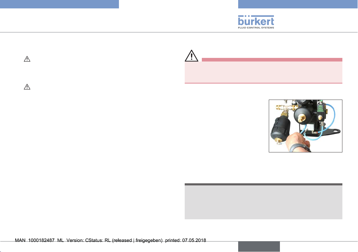
Removing the pneumatic unit:
→ Close the compressed-air supply and ventilate the pneumatic
unit.
→ 1. Unscrew and remove the screws on the input and output side
of the supply hose and connection hose leading to the robot.
→ 2. Unscrew and remove the screw on the unit's T-fitting leading
to the tip dresser (or another peripheral device).
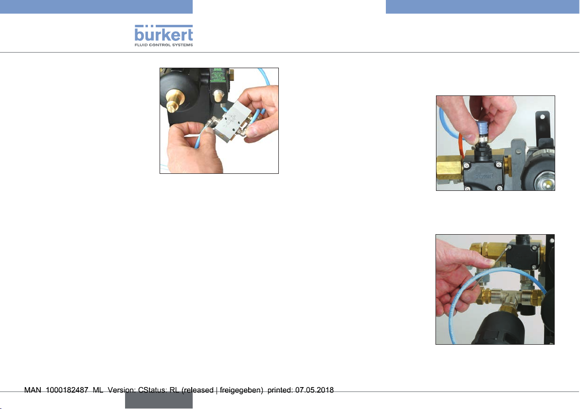
→ 3. Remove the plug-in hose
connection for the control air
to the MasterJet.
Fig. 24: Releasing the plug-in
hose on the pneumatic
unit
→ Release and remove the
pressure switch plug pin on
the input side of the pneumatic unit using a short flatblade screwdriver.
Fig. 25: Releasing the pressure
switch plug pin
→ Unscrew the pneumatic
unit from the fixture using a
hexagon socket screwdriver.
Fig. 26: Unscrewing the pneu-
matic unit from the fixture
Installation of the new pneumatic unit:
Install the new pneumatic unit in reverse order to that described in
the disassembly instructions.
34
Page 35

Type 8821
english
Shutdown
14. SHUTDOWN
14.1. Safety instructions
DANGER!
Risk of injury from high pressure in the system!
• Turn off the pressure and vent the lines before loosening lines
or valves.
Risk of injury due to electrical shock!
• Switch off the power supply and secure it against reactivation
before reaching into the device or equipment!
• Observe applicable accident prevention and safety regulations
for electrical equipment!
WARNING!
Risk of injury from improper removal!
• Removal may be carried out by authorized technicians only and
with the appropriate tools!
14.2. Disassembly of Type 8821
DANGER!
Risk of injury from falling robot!
Following disassembly of Type 8821, the robot must be screwed
back into place so that it cannot disconnect from the base frame
and fall over.
• Ensure that the required spring washers are inserted before the
fastening screws are secured.
• Ensure that the correct spring washers are inserted.
35
Page 36

15. TRANSPORTATION, STORAGE,
english
DISPOSAL
NOTE!
Transport damages!
Inadequately protected devices may be damaged during
transportation.
• Protect the device against moisture and dirt in shock-resistant
packaging during transportation.
• Prevent the temperature from exceeding or dropping below the
permitted storage temperature.
• Protect the electrical interfaces of the coil and pneumatic connections from damage by placing protective caps on them.
Incorrect storage may damage the device.
• Store the device in a dry and dust-free location!
• Storage temperature -40 to 55°C.
Damage to the environment caused by device components
contaminated with media.
• Ensure that the device and packaging are disposed of in an
environmentally sound manner!
• Observe applicable disposal and environmental regulations.
Type 8821
Transportation, Storage, Disposal
36
Page 37

Typ 8821
deutsch
Inhaltsverzeichnis
1. DIE BEDIENUNGSANLEITUNG ............................................................39
1.1. Darstellungsmittel ...........................................................................39
1.2. Begriffsdefinition ...........................................................................39
2. BESTIMMUNGSGEMÄSSE VERWENDUNG ................................... 40
2.1. Beschränkungen ............................................................................40
3. GRUNDLEGENDE SICHERHEITSHINWEISE .................................40
4. ALLGEMEINE HINWEISE .......................................................................... 41
4.1. Kontaktadressen .............................................................................41
4.2. Gewährleistung...............................................................................41
4.3. Informationen im Internet ..............................................................41
5. SYSTEMBESCHREIBUNG
5.1. Vorgesehener Einsatzbereich ......................................................42
5.2. Allgemeine Beschreibung ............................................................42
5.3. Funktionen........................................................................................42
6. TECHNISCHE DATEN ................................................................................ 43
6.1. Konformität .......................................................................................43
6.2. Normen .............................................................................................43
6.3. Betriebsbedingungen ....................................................................43
6.4. Allgemeine technische Daten ......................................................43
6.5. Prinzipschaltbild ..............................................................................46
7. MONTAGE
7.1. Sicherheitshinweise .......................................................................47
7.2. Montage der Funktionseinheit .....................................................47
........................................................................................................ 47
....................................................................... 42
8. INSTALLATION
8.1. Sicherheitshinweise .......................................................................49
8.2. Pneumatische Installation .............................................................49
8.3. Hydraulische Installation ...............................................................50
8.4. Stückliste Verschraubungen ........................................................50
8.5. Verschraubungsübersicht MasterJet mit Pneumatikeinheit . . 51
8.6. Elektrische Installation ...................................................................52
8.7. Elektrische Installation ...................................................................53
9. INBETRIEBNAHME
9.1. Sicherheitshinweise .......................................................................54
9.2. Inbetriebnahme Pneumatikeinheit ..............................................54
9.3. Inbetriebnahme Typ 8821 ............................................................55
10. BEDIENUNG
10.1. Sicherheitshinweise.....................................................................56
10.2. Manuelle Bedienung des MasterJets ......................................57
10.3. Automatisierte Bedienung des MasterJets ............................57
10.4. Sensor-Programmierung ............................................................58
11. WARTUNG
11.1. Sicherheitshinweise.....................................................................60
12. ERSATZTEILE
...............................................................................................49
......................................................................................54
.................................................................................................56
......................................................................................................60
............................................................................................... 61
37
Page 38

13. REPARATUR ..................................................................................................62
deutsch
13.1. Austausch Pilotventil Typ 6014 ................................................62
13.2. Austausch Pilotventil Typ 0450 ................................................63
13.3. Austausch Durchflusssensor SE12 .........................................64
13.4. Austausch Display- und Auswerteeinheit
(Elektronikmodul SE32) ................................................................65
13.5. Austausch Antrieb DM63 und DM50 .....................................66
13.6. Austausch des Expansionsszylinders DM63 .........................67
13.7. Austausch Pneumatikeinheit .....................................................68
Typ 8821
14. AUSSERBETRIEBNAHME
14.1. Sicherheitshinweise.....................................................................69
14.2. Demontage des Typs 8821 .......................................................69
15. TRANSPORT, LAGERUNG, ENTSORGUNG ................................. 70
38
..................................................................... 69
Page 39

Typ 8821
deutsch
Die Bedienungsanleitung
1. DIE BEDIENUNGSANLEITUNG
Die Bedienungsanleitung beschreibt den gesamten Lebenszyklus
des Geräts. Bewahren Sie diese Anleitung so auf, dass sie für jeden
Benutzer gut zugänglich ist und jedem neuen Eigentümer des Geräts
wieder zur Verfügung steht.
Die Bedienungsanleitung enthält wichtige Informationen zur
Sicherheit!
Das Nichtbeachten dieser Hinweise kann zu gefährlichen Situationen führen.
• Die Bedienungsanleitung muss gelesen und verstanden werden.
1.1. Darstellungsmittel
GEFAHR!
Warnt vor einer unmittelbaren Gefahr!
• Bei Nichtbeachtung sind Tod oder schwere Verletzungen die
Folge.
WARNUNG!
Warnt vor einer möglicherweise gefährlichen Situation!
• Bei Nichtbeachtung drohen schwere Verletzungen oder Tod.
VORSICHT!
Warnt vor einer möglichen Gefährdung!
• Nichtbeachtung kann mittelschwere oder leichte Verletzungen
zur Folge haben.
HINWEIS!
Warnt vor Sachschäden!
• Bei Nichtbeachtung kann das Gerät oder die Anlage beschädigt
werden.
bezeichnet wichtige Zusatzinformationen, Tipps und
Empfehlungen.
verweist auf Informationen in dieser Bedienungsanleitung
oder in anderen Dokumentationen.
→ markiert einen Arbeitsschritt, den Sie ausführen müssen.
1.2. Begriffsdefinition
Der in dieser Anleitung verwendete Begriff „Funktionseinheit“
besteht in der Maximalausführung aus den Komponenten:
MasterJet, Pneumatikeinheit und Sockelaufbau.
In der Minimalausführung nur aus den Komponenten:
Pneumatikeinheit und Sockelaufbau.
39
Page 40

Typ 8821
deutsch
Bestimmungsgemäße Verwendung
2. BESTIMMUNGSGEMÄSSE
VERWENDUNG
Bei nicht bestimmungsgemäßem Einsatz der Funktionseinheit können Gefahren für Personen, Anlagen in der
Umgebung und die Umwelt entstehen.
• Die Funktionseinheit ist für die Steuerung und Überwachung
von Kühlkreisläufen an industriellen Produktionsanlagen
konzipiert.
• Die Funktionseinheit darf nicht in explosionsgefährdeten Bereichen eingesetzt werden.
• Für den Einsatz die in den Vertragsdokumenten und der Bedienungsanleitung spezifizierten zulässigen Daten, Betriebs- und
Einsatzbedingungen beachten. Diese sind im Kapitel „Technische Daten“ beschrieben.
• Die Funktionseinheit darf nur in Verbindung mit von Bürkert
empfohlenen bzw. zugelassenen Fremdgeräten und -komponenten eingesetzt werden.
• Voraussetzungen für den sicheren und einwandfreien Betrieb
sind sachgemäßer Transport, sachgemäße Lagerung und Installation sowie sorgfältige Bedienung und Instandhaltung.
• Nehmen Sie keine äußerlichen Veränderungen an den Gerätegehäusen vor. Gehäuseteile und Schrauben nicht lackieren.
• Setzen Sie die Funktionseinheit nur bestimmungsgemäß ein.
2.1. Beschränkungen
Beachten Sie bei der Ausfuhr des Systems/Geräts gegebenenfalls
bestehende Beschränkungen.
3. GRUNDLEGENDE
SICHERHEITSHINWEISE
Diese Sicherheitshinweise berücksichtigen keine
• Zufälligkeiten und Ereignisse, die bei Montage, Betrieb und Wartung
der Geräte auftreten können.
• ortsbezogenen Sicherheitsbestimmungen, für deren Einhaltung, auch
in Bezug auf das Montagepersonal, der Betreiber verantwortlich ist.
Gefahr durch hohen Druck!
• Vor dem Lösen von Leitungen oder Ventilen den Druck abschalten und Leitungen entlüften.
Gefahr durch elektrische Spannung!
• Vor Eingriffen in das Gerät oder die Anlage die Spannung
abschalten und vor Wiedereinschalten sichern!
• Die geltenden Unfallverhütungs- und Sicherheitsbestimmungen
für elektrische Geräte beachten!
Allgemeine Gefahrensituationen.
Zum Schutz vor Verletzungen ist zu beachten:
• Speisen Sie in die Medienanschlüsse des Systems keine
aggressiven oder brennbaren Medien ein.
• Speisen Sie in die Druckluftanschlüsse keine Flüssigkeiten ein.
• Der Trittschutz an der Oberseite des Geräts darf nicht mit mehr
als 70 kg belastet werden.
• Dass die Anlage nicht unbeabsichtigt betätigt werden kann.
40
Page 41

Typ 8821
deutsch
Allgemeine Hinweise
• Installations- und Instandhaltungsarbeiten dürfen nur von autorisiertem Fachpersonal mit geeignetem Werkzeug ausgeführt
werden.
• Nach einer Unterbrechung der elektrischen oder pneumatischen
Versorgung ist ein definierter oder kontrollierter Wiederanlauf
des Prozesses zu gewährleisten.
• Das Gerät darf nur in einwandfreiem Zustand und unter Beachtung der Bedienungsanleitung betrieben werden.
• Für die Einsatzplanung und den Betrieb des Gerätes müssen
die allgemeinen Regeln der Technik eingehalten werden.
HINWEIS!
Elektrostatisch gefährdete Bauelemente / Baugruppen!
Das Gerät enthält elektronische Bauelemente, die gegen elektrostatische Entladung (ESD) empfindlich reagieren. Berührung
mit elektrostatisch aufgeladenen Personen oder Gegenständen
gefährdet diese Bauelemente. Im schlimmsten Fall werden sie
sofort zerstört oder fallen nach der Inbetriebnahme aus.
• Beachten Sie die Anforderungen nach EN 61340-5-1 und -5-2,
um die Möglichkeit eines Schadens durch schlagartige elektrostatische Entladung zu minimieren bzw. zu vermeiden!
• Achten Sie ebenso darauf, dass Sie elektronische Bauelemente
nicht bei anliegender Versorgungsspannung berühren!
4. ALLGEMEINE HINWEISE
4.1. Kontaktadressen
Deutschland
Bürkert Fluid Control Systems
Technik Center
Christian-Bürkert-Str. 13-17
D-74653 Ingelfingen
Tel. + 49 (0) 7940 - 10 91 110
Fax + 49 (0) 7940 - 10 91 448
E-mail: info@de.buerkert.com
International
Die Kontaktadressen finden Sie auf den letzten Seiten der
gedruckten Bedienungsanleitung.
Außerdem im Internet unter:
www.burkert.com
4.2. Gewährleistung
Voraussetzung für die Gewährleistung ist der bestimmungsgemäße
Gebrauch der Funktionseinheit unter Beachtung der spezifizierten
Einsatzbedingungen.
4.3. Informationen im Internet
Bedienungsanleitungen und Datenblätter zum Typ 8821 finden Sie
im Internet unter:
www.buerkert.de
41
Page 42

Typ 8821
deutsch
Systembeschreibung
5. SYSTEMBESCHREIBUNG
5.1. Vorgesehener Einsatzbereich
Der Typ 8821 ist für den Einsatz in industriellen Anlagen, insbesondere Roboterapplikationen zum Widerstandspunktschweißen
für die Steuerung und Überwachung von Kühlwasserkreisläufen
konzipiert.
5.2. Allgemeine Beschreibung
Der Typ 8821 dient der Steuerung und Überwachung des
Kühlmittelflusses in industriellen Roboteranwendungen zum
Widerstandspunktschweißen.
Durch die Einheit wird der Kühlwasserkreislauf gesteuert und die
geforderte Kühlmittelmenge überwacht.
Darüberhinaus wird bei Abschaltung des Kühlwasserstroms der im
System eingesperrte Wasserdruck abgebaut.
Dies ist beim Wechsel der Schweißelektroden vorteilhaft, da der
Kühlwasseraustritt dabei vermieden wird.
5.3. Funktionen
• Die Steuerung der Hauptventile (NC) von Vor- und Rücklauf des
Kühlkreislaufs erfolgt über ein Vorsteuerventil Typ 6014.
• Die Druckreduzierung im Kühlsystem wird beim Abschalten automatisch durch die verzögerte Antriebansteuerung im Rücklauf realisiert.
• Die Restdruckentspannung erfolgt über ein verzögert geschaltetes
Pilotventil Typ 0450 und einem pneumatischen Expansionszylinder
DM63 im geschlossenen Kühlkreislauf.
• Ein optischer Kühlwasserdurchflusssensor Typ 8012 DN8, bestehend
aus einer Auswerteelektronik mit integriertem Flügelrad SE12, Fitting
SO30 und Elektronikmodul SE32, überwacht die Durchflussrate und
schaltet entsprechend der programmierten Überwachungsfenster
Signalausgänge an die übergeordnete Steuerung oder den Roboter.
• Der Durchflusssensor verfügt über eine Durchflussrichtungserkennung.
• Die Kühlwasserdurchflussmenge kann über eine manuelle Justierschraube am pneumatischen Zulaufantrieb begrenzt werden.
42
Page 43

Typ 8821
deutsch
Technische Daten
6. TECHNISCHE DATEN
6.1. Konformität
Der Typ 8821 ist konform zu den EG-Richtlinien entsprechend der
EG-Konformitätserklärung.
6.2. Normen
Die angewandten Normen, mit denen die Konformität mit den EGRichtlinien nachgewiesen wird, sind in der EG-Baumusterprüfbescheinigung und/oder der EG-Konformitätserklärung nachzulesen.
6.3. Betriebsbedingungen
WARNUNG!
Verletzungsgefahr!
Funktionsausfall bei Einsatz im Außenbereich!
• Typ 8821 nicht im Außenbereich einsetzen und Wärmequellen,
die zur Überschreitung des zulässigen Temperaturbereichs
führen können, vermeiden.
Zulässige Temperaturen
Umgebungstemperatur: +5 ... +55 °C
Mediumstemperatur: +5 ... +90 °C
Medien: aggressive und neutrale flüssige Medien
Schutzart: IP65 nach EN 60529
6.4. Allgemeine technische Daten
Gewicht: 9,5 kg
Gehäusematerial: VA / Messing
Dichtungsmaterial außen: EPDM
6.4.1. Abmessungen
271,3
6
199,5
5
199,8
85,6
276,3
Bild 1: Typ 8821, MasterJet mit Pneumatikeinheit und Sockelaufbau;
Rückansicht
43
Page 44

Typ 8821
deutsch
Technische Daten
199,5
216,1
Bild 2: Typ 8821, MasterJet mit Pneumatikeinheit und Sockelaufbau;
Unteransicht
216
192,6
Bild 3: Typ 8821, MasterJet mit Pneumatikeinheit und Sockelaufbau;
Seitenansicht links
44
Page 45

Typ 8821
deutsch
Technische Daten
6.4.2. Pneumatische Daten
Steuermedium : Qualitätsklassen nach DIN ISO 8573-1
Staubgehalt: Klasse 5: max. Teilchengröße 40 μm,
max. Teilchendichte 10 mg/m
3
Wassergehalt: Klasse 3: max. Drucktaupunkt –20 °C oder
min. 10 °C unterhalb der niedrigsten
Betriebstemperatur
Ölgehalt: Klasse 5: max. 25 mg/m
3
Temperaturbereich
der Druckluft: –10 ... +50 °C
Druckbereich 3,0 ... 9,5 bar
Luftleistung IN/min
(für Be- und Entlüftung) (QNn-Wert nach Definition bei
Druckabfall von 7 auf 6 bar absolut)
Anschlüsse Schlauchsteckverbinder
Ø 6 mm / 1/4"
6.4.3. Hydraulische Daten
Medium: Wasser, Kühlwasser
Max. Betriebsdruck: 9,5 bar
Umgebungstemperatur: +5 ... +55 °C
Wasseranschlüsse
am Block: siehe „Bild 7“ auf Seite 51
6.4.4. Elektrische Daten
Ventil
Anschluss: DIN 43650 Form B mit M12 Adapter
Spannungsversorgung: 24 V DC
Sensor:
Anschluss: M12 Gerätestecker
Spannungsversorgung: 12 - 30 V DC
Messgenauigkeit: +/– 1% vom Endwert, 3 % Messwert bei
einem Durchfluss von 0,3 - 10 m/s
Ausgang: 1 Impuls / Umdrehung, Transistor NPN
700 mA
45
Page 46

6.5. Prinzipschaltbild
deutsch
Typ 8821
Technische Daten
P Druckinstallation
kundenseitig
P 5-10 bar
Pneumatik zu
Roboter
3
1
3/2-Wege-Ventil
(6014) 24VDC
ø 0,05
5/2-Wege-Ventil (0450)
pneumatisch gesteuert
Stopfen
4
3 1
Vorlauf
Versorgung
kundenseitig
Rücklauf
ø 0,5
2
Ventilzulauf 1
(2031) DN15
Ventilrücklauf 2
(2031) DN15
ø 0,5
Entlüftung
Luft
Wasser
Durchflusssensor
SE12 DN08
2
Vorlauf
Punktschweißzange
Rücklauf
Anzeige SE32
Bild 4: Prinzipschaltbild
46
Page 47

Typ 8821
deutsch
Montage
7. MONTAGE
7.1. Sicherheitshinweise
GEFAHR!
Verletzungsgefahr durch hohen Druck in der Anlage!
• Vor dem Lösen von Leitungen oder Ventilen den Druck abschalten und Leitungen entlüften.
Verletzungsgefahr durch Stromschlag!
• Vor Eingriffen in das Gerät oder die Anlage die Spannung
abschalten und vor Wiedereinschalten sichern!
• Die geltenden Unfallverhütungs- und Sicherheitsbestimmungen
für elektrische Geräte beachten!
WARNUNG!
Verletzungsgefahr bei unsachgemäßer Montage!
• Die Montage darf nur autorisiertes Fachpersonal mit geeignetem Werkzeug durchführen!
Verletzungsgefahr durch ungewolltes Einschalten der Anlage
und unkontrollierten Wiederanlauf!
• Anlage vor unbeabsichtigtem Betätigen sichern.
• Nach der Montage einen kontrollierten Wiederanlauf
gewährleisten.
7.2. Montage der Funktionseinheit
WARNUNG!
Verletzungsgefahr durch plötzlichen Kühlwasseraustritt bei
unsachgemäßem Einbau!
Bei falscher Einbaulage (Orientierung horizontal oder kopfüber)
ist die Entlastungsfunktion des Expansionszylinders nicht mehr
gewährleistet. Dadurch kann es beim Elektrodenkappenwechsel
an der Punktschweißzange zu einem plötzlichen Kühlwasseraustritt kommen.
• Die Funktionseinheit nur senkrecht stehend einbauen.
• Einbaulage unbedingt beachten.
Vorgehensweise:
→ Den MasterJet mittels den dafür vorgesehenen Bohrungen an
eine Grundplatte oder Halterung anschrauben (siehe „Bild 5“ und
„Bild 6“).
HINWEIS!
• Beachten Sie die Einbaulage der Funktionseinheit. Die Trittschutzplatte ist bei korrekter Montage oben!
47
Page 48

Typ 8821
deutsch
Montage
88
88
Bild 5: Anschraubbohrungen in Grundplatte
Für den Anbau am Roboterfuß kann eine Halterung passend zum
Schraubenlochbild des Roboters geliefert werden.
Artikelbezeichung und Bestellnummer:
Winkelhalter komplett 771338
Siehe Kapitel „12. Ersatzteile“ auf Seite 61
48
Halterung für die Montage
am Roboterfuß
Bild 6: MasterJet mit Halterung für Anbau am Roboterfuß
7.2.1. Anbaumöglichkeiten:
Grundsätzlich sind bei der Montage des MasterJets unterschiedliche
Anbaumöglichkeiten zulässig.
Empfehlung:
Die Einheit möglichst nahe am Prozess (z.B. Punktschweißzange)
montieren.
Bei großem Abstand entstehen lange Schlauchwege. Dies hat folgenden Auswirkungen:
• Die zu entspannende Kühlmittelmenge nimmt zu. Deshalb muss
der Expansionszylinder entsprechend größer gewählt werden.
• Verzögerte Reaktionszeiten auf Durchflussänderungen, wie sie z.B.
bei Elektrodenkappenabriss an der Punktschweißzange auftreten
können.
Die Erkennung von solchen und anderen Fehlerzuständen ist
deshalb ebenfalls verzögert.
Page 49

Typ 8821
deutsch
Installation
8. INSTALLATION
8.1. Sicherheitshinweise
GEFAHR!
Verletzungsgefahr durch hohen Druck in der Anlage!
• Vor dem Lösen von Leitungen oder Ventilen den Druck abschalten und Leitungen entlüften.
Verletzungsgefahr durch Stromschlag!
• Vor Eingriffen in das Gerät oder die Anlage die Spannung
abschalten und vor Wiedereinschalten sichern!
• Die geltenden Unfallverhütungs- und Sicherheitsbestimmungen
für elektrische Geräte beachten!
WARNUNG!
Verletzungsgefahr bei unsachgemäßer Installation!
• Die Installation darf nur autorisiertes Fachpersonal mit geeignetem Werkzeug durchführen!
Verletzungsgefahr durch ungewolltes Einschalten der Anlage
und unkontrollierten Wiederanlauf!
• Anlage vor unbeabsichtigtem Betätigen sichern.
• Nach der Installation einen kontrollierten Wiederanlauf
gewährleisten.
8.2. Pneumatische Installation
GEFAHR!
Verletzungsgefahr durch hohen Druck in der Anlage!
• Vor dem Lösen von Leitungen oder Ventilen den Druck abschalten und Leitungen entlüften.
Vorgehensweise:
→ Nach dem mechanischen Anbau des MasterJets den pneuma-
tischen Anschluss zwischen Pneumatikeinheit und MasterJet
herstellen:
→ Die werksseitige Luftversorgung an die Pneumatikeinheit anschließen.
Siehe „Bild 7: Verschlauchungsübersicht Typ 8821“
Die Luftmengenerfordernisse in der Roboterapplikation
beachten.
Der MasterJet benötigt einen Steckschlauchanschluss mit
6 mm Durchmesser. Die Roboterapplikation benötigt einen
1/2“-Anschluss (Standard in den meisten Rohbauapplikationen ist 1/2“ auf M22 x 1,5 oder äquivalent).
→ Am T-Stück der Wartungseinheit ausgangsseitig den Verbindungs-
schlauch zum Roboterfuß oder zu einer stationären Schweißzange
anschließen.
→ Die Verschraubungen anziehen.
49
Page 50

Typ 8821
deutsch
Installation
HINWEIS!
Sachschäden durch zu hohen Eingangsdruck!
• Der werkseitig vorgehaltene Luftdruck darf den maximal zulässigen Druck an der Funktionseinheit nicht übersteigen.
• Bei höherem als zugelassenem Eingangsdruck einen entsprechenden Druckminderer einsetzen!
8.3. Hydraulische Installation
HINWEIS!
Beschädigung der Verschraubungen durch unsachgemäßes
Anziehen!
• Beim Anziehen der Universaldichtköpfe das maximale Drehmoment bzw. 1/4 Umdrehung Anziehweg beachten, da sonst die
Verschraubung reißen kann.
Vorgehensweise:
→ Eingangsseitig am MasterJet mittels der beigelegten Verschrau-
bungen die hallenseitige Kühlwasserversorgung Vorlauf und
Rücklauf anschließen.
HINWEIS!
Fehlfunktion des MasterJets bei vertauschtem Vor- und
Rücklauf!
Bei vertauschter Fließrichtung wird ein bestehender Wasserfluss
nicht gemessen.
• Beim Anschluss der Kühlwasserversorung die Fließrichtung
beachten.
→ Die mitgelieferten Steckschläuche abhängig vom Abstand
Ausgang MasterJet und Anschlussstelle Roboterfuß ablängen.
Die Schläuche so lang lassen, dass sie mit großen
Biegeradien verlegt werden können. Durch zu enge Biegeradien
wird der Wasserfluss behindert.
→ Nun die vorbereiteten Schläuche am MasterJet ausgangsseitig
und am Roboterfuß anschließen.
Die Schlauchfarben und die farblich gekennzeichneten
Anschlüsse am Roboterfuss beachten:
Vorlauf = grün, Rücklauf = rot).
8.4. Stückliste Verschraubungen
Position Materialnummer Stück
1. GE15LREDOMDCF 1
2. 3C382-15-8 1
3. EVGE22LR3/4KEGMS 1
4. GE22LR3/4KEGMSX 1
5. 3D082-22-12B 1
6. 3C382-22-12B 1
7. EVGE15LR1/2KEGMS 1
8. GE15LR1/2KEGMSX 1
9. 3D082-15-8B 1(2)
10. 3C382-15-8B 1
11. 35C82-15-8B (2)
12. H898202 (1)
Tab. 1: Stückliste Verschraubungen
50
Page 51

Typ 8821
deutsch
Installation
8.5. Verschraubungsübersicht MasterJet mit Pneumatikeinheit
am Roboterfuß an der Funktionseinheit/ Ausgang an der Funktionseinheit / Eingang
Pneumatikverbindungen
Universaldichtkopf H898202 *) Doppelnippel GE15LREDOMDCF
35C82-15-8B + Universaldichtkopf 3C382-15-8
Kühlwasserverbindungen
Universaldichtkopf 35C82-15-8B *) Vorlauf Doppelnippel EVGE15LR1/2KEGMS Rücklauf Doppelnippel EVGE22LR3/4KEGMS
+ Schlauchverschraubung 3D082-15-8B + Schlauchverschraubung 3D082-22-12B
Universaldichtkopf 3D082-15-8B *) Rücklauf Doppelnippel GE15LR1/2KEGMSX Vorlauf Doppelnippel GE22LR3/4KEGMSX
+ Universaldichtkopf 3C382-15-8B + Universaldichtkopf 3C382-22-12B
*) im Beipack
Tab. 2: Verschraubungsübersicht
Biegeradius
Beim
Legen der
Schläuche
auf ausreichend große
Biegeradien
achten!
Bild 7: Verschlauchungsübersicht Typ 8821
51
Page 52

Typ 8821
deutsch
Installation
8.6. Elektrische Installation
GEFAHR!
Verletzungsgefahr durch Stromschlag!
• Vor Eingriffen in das Gerät oder die Anlage die Spannung abschalten und vor Wiedereinschalten sichern!
• Die geltenden Unfallverhütungs- und Sicherheitsbestimmungen für elektrische Geräte beachten!
Übersicht: Elektrische Steckerbelegung
SE12
nicht belegt
4
5
1
V+ (12-36 VDC)
Anschluss des 5-poligen M12
Kunststoff-Gerätesteckers
Bild 8: Elektrischer Anschluss; Steckerübersicht
52
0 V DC
3
Kabellänge max. 10 m
2
Impuls Ausgang
(Default NPN)
SE32
0 V DC
3
2
Impuls Eingang
(Default NPN)
Anschluss des 4-poligen
M12 Metallsteckers
nicht belegt
4
1
V+ (Sensor)
PNP-TransistorAusgang
4
5
1
V+ (12-36 V DC)
Anschluss des 5-poligen
Kunststoff-Gerätesteckers
0 V DC
3
2
NPN-TransistorAusgang
Page 53

Typ 8821
deutsch
Installation
Zuordnung der Adernfarben:
Pin Aderfarbe
1 braun
2 weiß
3 blau
4 schwarz
5 grau
Tab. 3: Elektrischer Anschluss; Adernfarben
8.7. Elektrische Installation
GEFAHR!
Verletzungsgefahr durch Stromschlag!
• Vor Eingriffen in das Gerät oder die Anlage die Spannung
abschalten und vor Wiedereinschalten sichern!
• Die geltenden Unfallverhütungs- und Sicherheitsbestimmungen
für elektrische Geräte beachten!
Vorgehensweise:
→ Den Durchflusssensor SE12 DN08 über das Verbindungskabel
(ID-Nummer 555676) mit der Display- und Auswerteeinheit
(Elektronikmodul SE32) verbinden. Dazu den M12-StandardStecker mit Schraubverriegelung aufschrauben.
Die Display-und Auswerteeinheit (Elektronikmodul SE32) kann
mechanisch an einem beliebigen Ort im Längenbereich des
Verbindungskabels montiert werden (z. B. am Schutzzaun).
→ Am 5-poligen M12-Gerätestecker die Versorgungsspannung für
die Display- und Auswerteeinheit (Elektronikmodul SE32) anlegen.
(siehe „Bild 8: Elektrischer Anschluss; Steckerübersicht“).
→ Am gleichen Stecker können die Auswertesignale der Einheit bei
Alarm etc. an die übergeordnete Steuerung oder den Roboter
durch entsprechende Verkabelung übergeben werden (siehe
Anschlussbild mit NPN- und PNP-Ausgang).
HINWEIS!
Beachten Sie die maximale Lastkapazität an den Ausgängen!
• Bei Nichtbeachtung kann das Gerät überlastet werden und die
Elektronik dabei Schaden nehmen.
53
Page 54

Typ 8821
deutsch
Inbetriebnahme
9. INBETRIEBNAHME
9.1. Sicherheitshinweise
WARNUNG!
Verletzungsgefahr bei unsachgemäßem Betrieb!
Nicht sachgemäßer Betrieb kann zu Verletzungen sowie Schäden
am Gerät und seiner Umgebung führen.
• Vor der Inbetriebnahme muss gewährleistet sein, dass der Inhalt
der Bedienungsanleitung dem Bedienungspersonal bekannt ist
und vollständig verstanden wurde.
• Die Sicherheitshinweise und die bestimmungsgemäße Verwendung müssen beachtet werden.
• Nur ausreichend geschultes Personal darf die Anlage/das Gerät
in Betrieb nehmen.
9.2. Inbetriebnahme Pneumatikeinheit
Zum Test des MasterJets muss zuerst die Pneumatikeinheit in Betrieb
genommen werden, da die Steuerventile und der Expansionszylinder
des MasterJets über Druckluft gesteuert werden.
GEFAHR!
Verletzungsgefahr durch nicht verbundene herumschlagende
Druckluftschläuche!
• Vor Beaufschlagung der Pneumatikeinheit mit Druckluft alle
Schlauchverbindungen auf festen Sitz prüfen.
• Das Entlüftungs-Absperrventil bei der Erstinbetriebnahme
zunächst geschlossen halten.
Vorgehensweise:
→ Die Luftversorgungsleitung zur Eingangsseite der Pneumatik-
einheit öffnen.
→ Die Druckluftverbindungen überprüfen und bestehende Luftle-
ckage durch geeignete Maßnahme abstellen.
→ Wenn keine Luftleckagen vorhanden sind das Entlüftungs-
Absperrventil öffnen.
→ Die Druckluftverbindungen und Komponenten der Pneumatik-
einheit ebenfalls auf Leckage überprüfen.
→ Sicherstellen, dass keine Leckagen vorhanden sind.
→ Nun die elektrische Rückmeldung des Druckschalters prüfen.
→ Prüfen, ob der Eingang an der angeschlossenen SPS oder
Robotersteuerung im Schaltzustand logisch „1“ ist.
Beachten Sie den korrekten Versorgungsdruck am Eingang
der Pneumatikeinheit. Dieser sollte zwischen 3 und 6 bar
betragen.
→ Nach Abschaltung des Entlüftungs-Absperrventils sollte der
elektrische Eingang der angeschlossenen SPS oder Robotersteuerung in den Schaltzustand logisch „0“ wechseln.
Damit ist die Inbetriebnahme der Pneumatikeinheit abgeschlossen.
54
Page 55

Typ 8821
deutsch
Inbetriebnahme
9.3. Inbetriebnahme Typ 8821
Nachdem
• das angeschlossene Leitungssystem mit Druckluft und Kühlwasser beaufschlagt ist und
• die Pneumatikeinheit in Betrieb genommen ist,
• erfolgt die Inbetriebnahme der Funktionseinheit.
Vorgehensweise:
→ Nach Öffnen des Kühlwasserflusses die Leitungszuführung zum
MasterJet eingangsseitig auf Leckagen überprüfen.
→ Etwaige Leckagen der Schlauchanschlüsse des Kühlwasser-
kreises beseitigen.
→ Über die manuelle Ventilbetätigung am Pilotventil 6014 den
Kühlkreislauf starten (siehe „Bild 9“).
→ Die ausgangsseitigen Verschraubungen auf Dichtigkeit prüfen.
→ Wird der eingestellte Schwellenwert unterschritten, wird dies
über eine rote LED angezeigt.
→ Sind alle Bedingungen korrekt, kann bei laufendem Kühlwasser
die aktuelle Durchflussmenge auf dem Display der Auswerteeinheit (Elektronikmodul SE32) je nach Einstellung in Liter oder
Gallonen pro Minute abgelesen werden.
→ Mit der Stellschraube am Rücklaufventil des MasterJets kann
die maximale Durchflussmenge durch Öffnen der Kontermutter
und anschließendem Verdrehen der Schlitzschraube auf den
gewünschten Wert reduziert werden.
HINWEIS!
Geeignetes Werkzeug zur Einstellung der Durchflussmenge:
• Zur Durchflussreduzierung kann die Stellschraube mit einem
großen Sechskantschraubendreher feiner justiert werden. Dabei
mit einem Gabelschlüssel gegenhalten.
→ Im Programmier-Menü der Auswerteeinheit (Elektronikmodul
SE32) die Grenzwerte für die Durchflussüberwachung einstellen
(siehe „10.4.1. Programmier-Menü der Auswerteeinheit (Elektronikmodul SE32)“).
Das Einstellen weiterer Parameter und Schaltbedingungen sowie
Messeinheiten ist in der Bedienungsanleitung für das Elektronikmodul SE32 beschrieben.
→ Den Kühlkreislauf über die manuelle Ventilbetätigung am Pilot-
ventil 6014 nun abschalten (siehe „Bild 9“), um die elektrischen
Funktionen zu überprüfen.
→ Zur Prüfung der elektrischen Funktionen zuerst den korrespon-
dierenden Schaltausgang der SPS oder Robotersteuerung auf
den Schaltzustand logisch „1“ setzen.
Mit dem Schaltbefehl „1“ wird das Pilotventil 6014 angesteuert,
welches pneumatisch die Vor- und Rücklaufventile des MasterJets öffnet - der Kühlkreislauf steht.
Parallel und durch eine Blende im pneumatischen Ansteuerungskreis des Schaltventils des Expansionszylinders wird die Pneumatikseite im Expansionszylinder vor gedrückt. Das Wasser im
Expansionszylinder wird in den Kühlkreislauf gedrückt.
→ Nun den Schaltzustand des Schaltausgangs zurücksetzen.
55
Page 56

Typ 8821
deutsch
Bedienung
Der Kühlkreislauf wird dadurch geschlossen und die Luftkammer
im Expansionszylinder zeitverzögert entlüftet.
Der verbliebene Druck im Kühlkreislauf zur Punktschweißzange
entspannt sich in den Expansionszylinder.
WARNUNG!
Verletzungsgefahr durch herausschießendes Kühlwasser
oder Wasserdampf!
Beim Abziehen der Elektrodenkappe kann es, bei gleichzeitiger
Fehlfunktion des Expansionszylinders, zum Austritt von Kühlwasser
oder Wasserdampf kommen.
• Die Elektrodenkappen nur mit dem dafür vorgesehenen Werkzeug abziehen.
• Beim Abziehen der Elektrodenkappen Schutzbrille und Schutzkleidung tragen.
→ Zur Prüfung der Funktionalität des MasterJets die Elektro-
denkappe der Punktschweißzange abziehen.
Bei korrekter Funktion des MasterJets darf auch bei anstehendem Druck kein Wasser aus dem Elektrodenschaft spritzen.
Nach dem Funktionstest des Expansionszylinders ist die Inbetriebnahme abgeschlossen.
10. BEDIENUNG
10.1. Sicherheitshinweise
WARNUNG!
Gefahr durch unsachgemäßer Bedienung!
Nicht sachgemäße Bedienung kann zu Verletzungen sowie
Schäden am Gerät und seiner Umgebung führen.
• Das Bedienungspersonal muss den Inhalt der Bedienungsanleitung kennen und verstanden haben.
• Die Sicherheitshinweise und die bestimmungsgemäße Verwendung müssen beachtet werden.
• Nur ausreichend geschultes Personal darf die Anlage/das Gerät
bedienen.
56
Page 57

Typ 8821
deutsch
Bedienung
10.2. Manuelle Bedienung des
MasterJets
Es gibt 2 Möglichkeiten zur Aktivierung des Kühlkreislaufs:
• Entweder das Pilotventil Typ6014 mit +24VDC beschalten oder
• den Handhebel am Ventil umlegen
(90° im Uhrzeigersinn).
Handhebel
Bild 9: Pilotventil Typ 6014 mit Handhebel zur manuellen Ventilbetätigung
Die manuelle Bedienung wird bei der Inbetriebnahme des Systems
angewandt, um die Parameter der Durchflussüberwachung erstmalig
einstellen und dabei auch die aktuelle Durchflussmenge beobachten
zu können.
Über einen manuellen Aktivierungshebel am Pilotventil Typ 0450 kann
die korrekte Funktionalität des Expansionszylinders geprüft werden.
10.3. Automatisierte Bedienung des
MasterJets
Für die Aktivierung des Kühlkreislaufs wird per 24 V DC-Ausgang einer
SPS oder einer Robotersteuerung die Spule des Pilotventils Typ 6014
geschaltet, welches pneumatisch die Antriebe im Vorlauf und Rücklauf
des Kühlkreislaufs aktiviert – der Kühlkreislauf arbeitet.
Parallel zur Aktivierung des Kühlkreislaufs wird, über ein Pilotventil vom
Typ 0450 und eine Blende im Ansteuerkreis, der Expansionszylinder
DM63 verzögert pneumatisch aktiviert. Der im Vorlauf des Kühlwasserkreises verbaute Expansionszylinder drückt im aktivierten Zustand,
das im Zylinder befindliche Kühlwasser in den Kühlkreislauf.
Wird der Kühlkreislauf per Ansteuerung geschlossen (Abschaltung
des 24 V DC-Ausgangs am Pilotventil Typ 6014), wird auch die
Aktivierung des Expansionszylinders über dessen Pilotventil Typ 0450
abgeschaltet. Der bestehende Wasserdruck wird in den Expansionszylinder abgebaut.
Die Dimensionierung des Expansionszylinders ist von der
Länge und dem Durchmesser der Schläuche des Kühlkreises
abhängig. Die Standard-Auslegung sieht den Einsatz des
MasterJets am Roboterfuß vor.
Mit Aktivierung des Kühlkreislaufs wird der sich im Rücklauf befindliche
Durchflusssensor SE12 von Kühlwasser durchströmt.
Abhängig von der Durchflussmenge sendet der Durchflusssensor SE12
Impulse an die Display- und Auswerteeinheit (Elektronikmodul SE32).
Die Auswerteeinheit berechnet aus den eingehenden Impulsen die
Durchflussmenge und vergleicht sie mit den Minimal- und Maximalwerten, die vom Anwender vorgegeben wurden.
57
Page 58

Typ 8821
deutsch
Bedienung
Nach einer programmierbaren Ausblendzeit, in welcher bis zur Stabilisierung des Kühlkreislauf die aktuellen Durchflusswerte ignoriert
werden, wird bei korrekter Durchflussmenge ein Ausgang an die SPS
oder die Robotersteuerung gesetzt. Dieser Ausgang wird nur im Fehlerfall zurückgesetzt.
10.4. Sensor-Programmierung
Der Durchflusssensor SE12 ist mittels eines Verbindungskabels
mit der Display- und Auswerteeinheit (Elektronikmodul SE32)
verbunden.
Bild 10: Durchflusssensor mit Verbindungskabel und Auswerteeinheit
(Elektronikmodul SE32)
Die maximale Leitungslänge für das Verbindungskabel beträgt 10 m.
10.4.1. Programmier-Menü der
Auswerteeinheit (Elektronikmodul SE32)
In diesem Menü können folgende Parameter eingestellt werden:
• Mengeneinheit: Liter/Sekunde oder Liter/Minute.
• K-Faktor für den Durchflusssensor: Anzahl der Impulse pro Liter.
• Ausgangsverhalten (MODE): Festlegen von Unter- und Ober-
grenze des Schaltschwellenwerts und der Schaltverzögerungszeit.
• Filterwirkung: Einstellbereich von 0 bis 9.
• Bargraph-Skalierung: Unter- und Obergrenze festlegen.
Zugang zum Programmier-Menü:
Nach Anlegen der Betriebsspannung befindet sich die Auswerteeinheit (Elektronikmodul SE32) in der Lese-Ebene. Zur Programmierung muss in die Kalibrierebene gewechselt werden.
Wechsel in die Kalibrierebene:
Beide Tasten gleichzeitig ca.
5 Sekunden gedrückt halten.
58
Page 59

Typ 8821
deutsch
Bedienung
Funktion der Tasten in der Kalibrierebene:
Wechsel in den vorherigen Menüpunkt
Eingabe von Werten
Wert erhöhen
Zum Versetzen der Kommastelle beide Tasten
Wechsel in den
nächsten Menüpunkt
Wechsel um eine
Stelle nach links
• Menüpunkt
• Einstellungen
• Wechsel in die
gleichzeitig drücken.
Tab. 4: Funktion der Tasten in der Kalibrierebene
Menüstruktur:
Maßeinheit festlegen
UNIT
L/S
L/M
K-Faktor für Durchflusssensor einstellen
K-FAC
NO TEACH
144
Wert (144)
eingeben
bestätigen
übernehmen
Lese-Ebene
Ausgangsverhalten (MODE) einstellen
OUT
MODE
Schaltschwellenwert
eingeben
7.500
OLO
Untergrenze
8.500
OHI
Obergrenze
Schaltverzögerungszeit eingeben
00
Maßeinheit Sekunden
DEL
Filter einstellen
FILT
5
Einstellwert 0 ... 9
FILT
Bargraph skalieren
BRGR
0.600
BGLO
Untergrenze
INV
Invertierung
YES / NO
12.00
BGHI
Obergrenze
OUT
END
Bild 11: Menüstruktur; Programmierung SE32
Rückkehr in die Lese-Ebene
59
Page 60

Typ 8821
deutsch
Wartung
Weitere Informationen zur Bedienung und Programmierung der
Display- und Auswerteeinheit (Elektronikmodul SE32) finden Sie in
der zugehörigen Bedienungsanleitung.
11. WARTUNG
11.1. Sicherheitshinweise
GEFAHR!
Verletzungsgefahr durch hohen Druck in der Anlage!
• Vor dem Lösen von Leitungen oder Ventilen den Druck abschalten und Leitungen entlüften.
Verletzungsgefahr durch Stromschlag!
• Vor Eingriffen in das Gerät oder die Anlage die Spannung
abschalten und vor Wiedereinschalten sichern!
• Die geltenden Unfallverhütungs- und Sicherheitsbestimmungen
für elektrische Geräte beachten!
WARNUNG!
Verletzungsgefahr bei unsachgemäßen Wartungsarbeiten!
• Die Wartung darf nur autorisiertes Fachpersonal mit geeignetem
Werkzeug durchführen!
Verletzungsgefahr durch ungewolltes Einschalten der Anlage
und unkontrollierten Wiederanlauf!
• Anlage vor unbeabsichtigtem Betätigen sichern.
• Nach der Wartung einen kontrollierten Wiederanlauf
gewährleisten.
60
Page 61

Typ 8821
deutsch
Ersatzteile
12. ERSATZTEILE
Bestellnummern für Ersatzteile:
Position Teilebezeichnung Bestell-Nr.
1 Sensor SE12 558777
2 Fitting DN08 444571
3 Elektronikmodul SE32 563940
4 Pilotventil 6014 153771
5 Kabel für Sensor / Elektronikmodul SE32 555676
6 Expansionszylinder 211861
7 Pilotventil Entlastung Typ 0450 904258
8 Antrieb WWA/DM50 246737
9 Antrieb WWA/DM63 246738
10 max. Hubbegrenzung 637866
11 M12-Stecker 4-polig (ohne Abb.) 448856
12 Pneumatikeinheit komplett rechts 904230
13 Membrane 677664
Tab. 5: Ersatzteilübersicht
1
12
2
8
4
6
9
7
5
3
10
13
Bild 12: Ersatzteilübersicht
61
Page 62

Typ 8821
deutsch
Reparatur
13. REPARATUR
13.1. Austausch Pilotventil Typ 6014
GEFAHR!
Verletzungsgefahr durch hohen Druck in der Anlage!
• Vor dem Lösen von Leitungen oder Ventilen den Druck abschalten und Leitungen entlüften.
Ausbau des Pilotventils:
HINWEIS!
Funktionsstörung durch Vertauschen der
Steckschlauchanschlüsse
• Vor dem Lösen der Steckschläuche die Zugehörigkeit von
Schlauch und Verbinder kennzeichnen, damit ein Vertauschen
der Anschlüsse beim Wiederzusammenbau vermieden wird.
Vor dem Austausch des Pilotventils die pneumatische
Versorgung wie nachfolgend
beschrieben abstecken.
→ Der Verriegelungsring des
Steckverbinders nach hinten
drücken und zeitgleich den
Steckschlauch aus dem
Steckverbinder ziehen.
Bild 13: Pilotventil Typ 6014
austauschen
→ Alle anderen Steckschlauch-
anschlüsse in gleicher Weise
lösen und entfernen.
Bild 14: Steckschläuche abziehen
Nach dem Abstecken aller Steckschlauchverbindungen:
→ Den Stecker der elektrischen Ansteuerung M12 von der Ventil-
spule abschrauben.
Nun das Pilotventil Typ 6014 wie nachfolgend beschrieben
entfernen.
→ Die Durchsteckschraube mit
einem passenden Gabeloder Ringschlüssel lösen und
herausdrehen.
→ Das Ventil abnehmen.
Bild 15: Pilotventil Typ 6014
abschrauben
62
Page 63

Typ 8821
deutsch
Reparatur
Einbau des neuen Pilotventils:
→ Ventil aufstecken.
→ VORSICHT!
Vor dem Durchschieben der Durchsteckschraube den O-Ring
wieder einsetzen.
→ Durchsteckschraube einsetzen und mit einem Gabel- oder Ring-
schlüssel und einem Drehmoment von 1 Nm anziehen.
Den Drehmoment unbedingt beachten!
Durch zu starkes Anziehen der Schraube kann das Ventilgehäuse beschädigt werden.
→ Alle Steckschlauchverbindungen wieder herstellen. Dabei die
richtige Zuordnung von Schlauch und Verbinder beachten.
→ Den Stecker der elektrischen Ansteuerung M12 an die Ventil-
spule anschließen.
13.2. Austausch Pilotventil Typ 0450
GEFAHR!
Verletzungsgefahr durch hohen Druck in der Anlage!
• Vor dem Lösen von Leitungen oder Ventilen den Druck abschalten und Leitungen entlüften.
Ausbau des Pilotventils Typ 0450:
→ Mit einem Schlitzschrau-
bendreher die beiden
Befestigungsschrauben
zum Haltewinkel lösen und
herausdrehen.
Bild 16: Pilotventil Typ 0450
demontieren
HINWEIS!
Funktionsstörung durch Vertauschen der
Steckschlauchanschlüsse
• Vor dem Lösen der Steckschläuche die Zugehörigkeit von
Schlauch und Verbinder kennzeichnen, damit ein Vertauschen
der Anschlüsse beim Wiederzusammenbau vermieden wird.
63
Page 64

Typ 8821
deutsch
Reparatur
→ Am gelösten Ventil nun die
drei angeschlossenen Steckschläuche abziehen.
Bild 17: Steckschläuche am
Pilotventil Typ 0450 lösen
Einbau des neuen Ventils:
→ Alle Steckschlauchverbindungen wieder herstellen. Dabei die
richtige Zuordnung von Schlauch und Verbinder beachten.
→ Das Verschlussstück des ungenutzten Anschlusses vom ausge-
bauten Pilotventil Typ 0450 abstecken und auf das neue Ventil
aufstecken.
→ Das Ventil mit den beiden Befestigungsschrauben an den Halte-
winkel anschrauben.
13.3. Austausch Durchflusssensor SE12
Ausbau des Durchflusssensors:
→ Den M12-Stecker auf der
Oberseite des Sensorgehäuses abschrauben.
Bild 18: M12-Stecker am
Durchflusssensor SE12
abschrauben
→ Die 4 Befestigungsschrauben
des Sensorkopfs mit einem
passenden Imbusschlüssel
lösen und herausdrehen.
→ Sensorkopf abnehmen.
Bild 19: Sensorkopf demontieren
64
Page 65

Typ 8821
deutsch
Reparatur
Einbau des neuen Sensorkopfs:
→ Den Dichtungsring zum Fitting
auf Unversehrtheit und richtigen Sitz prüfen.
→ Sensorkopf auf das Fitting
aufsetzen.
→ Den Sensorkopf mit den
4 Imbusschrauben
befestigen.
Die 4 Imbusschrauben
dabei über Kreuz anziehen.
13.4. Austausch Display- und
Auswerteeinheit
(Elektronikmodul SE32)
Die Display- und Auswerteeinheit (Elektronikmodul SE32) ist mit
2 Kabeln verbunden. Das 4-polige Kabel mit dem M12-Kunststoffstecker dient der Spannungsversorgung und Datenübertragung
des Sensorkopfes SE12. Das 5-polige Kabel mit dem M12-Metallstecker ist für die Spannungsversorgung der Display- und Auswerteeinheit (Elektronikmodul SE32) und für die Signalkommunikation mit
der SPS oder der Robotersteuerung.
WARNUNG!
Verletzungsgefahr durch unkontrollierte Aktionen der Anlage
bei Arbeiten mit eingeschalteter Versorgungsspannung!
• Vor dem Austausch Spannung abschalten und vor Wiedereinschalten sichern!
Bild 20: Ausgebauter Sensorkopf
Ausbau der Auswerteeinheit (Elektronikmodul SE32)
→ Für den Ausbau der Display- und Auswerteeinheit (Elektronik-
modul SE32) die beiden M12-Stecker lösen und abziehen.
→ Zur mechanischen Entriegelung des SE32 an der Basisplatte die
versenkte Imbusschraube lösen.
→ Die Auswerteeinheit, durch Verdrehen um 30°, aus der Bajonett-
Halterung nehmen.
Einbau der neuen Auswerteeinheit (Elektronikmodul SE32):
→ Zum Einbau die Auswerteeinheit um 30° verdreht in die Bajonett-
halterung der Basisplatte setzen und in die Nulllage drehen.
→ Die Auswerteeinheit mittels der Fixierschraube sichern.
→ Zum Abschluss die beiden M12-Stecker wieder aufstecken und
verschrauben.
HINWEIS!
Funktionsstörung durch fehlende Konfiguration!
• Damit die ausgetauschte Display- und Auswerteeinheit (Elektronikmodul SE32) die geforderte Funktion erfüllt, muss sie
programmiert werden. Die Programmierung ist in der Bedienungsanleitung des Typs SE32 detailliert beschrieben.
65
Page 66

Typ 8821
deutsch
Reparatur
13.5. Austausch Antrieb DM63 und
DM50
Ausbau des Antriebs:
WARNUNG!
Verletzungsgefahr durch vorgespannte Feder!
Der Antrieb ist im Ruhezustand durch eine Feder intern vorgespannt (Durchfluss gestoppt). Die Federkraft kann sich beim Entfernen der Imbusschrauben schlagartig entspannen.
• Vor dem Entfernen der Schrauben den Druckluftanschluss mit
Druckluft beaufschlagen und den Druck als Gegendruck zur
Federkraft aufrechterhalten.
→ Druckluftanschluss mit Druckluft beaufschlagen und Druck
aufrechterhalten.
→ Auf der Rückseite des Mas-
terJets die 4 Imbusschrauben
mit einem Innensechskantschlüssel lösen und
herausdrehen.
→ Antrieb abnehmen.
Bild 21: Antrieb demontieren
Einbau des neuen Antriebs:
HINWEIS!
Beschädigung der Ventilmembrane durch Einbau ohne
Druckluftbeaufschlagung!
Wird der Antrieb ohne Druckluftbeaufschlagung eingebaut,
kann durch die Federkraft, die Ventilmembrane in den Ventilsitz
gedrückt und beschädigt werden.
• Vor dem Einbau das Ventil mit Druckluft beaufschlagen.
→ Vor dem Einbau des Antriebs den Druckluftanschluss mit
Druckluft beaufschlagen.
Dies ist wichtig, da sonst die Federkraft des Antriebs die Membrane so weit herausdrückt, dass die Imbusschrauben nicht
fassen können.
→ Antrieb aufsetzen.
→ Die 4 Imbusschrauben am Antriebsgehäuse gleichmäßig
anziehen, damit sich die Ventilmembrane nicht im Ventilaufbau
verkantet.
66
Page 67

Typ 8821
deutsch
Reparatur
13.6. Austausch des
Expansionsszylinders DM63
GEFAHR!
Verletzungsgefahr durch hohen Druck in der Anlage!
• Vor dem Lösen von Leitungen oder Ventilen den Druck abschalten und Leitungen entlüften.
Ausbau des Expansionszylinders:
Zunächst die pneumatische Ansteuerung am oberen Ende des
Expansionszylinders wie nachfolgend beschrieben entfernen.
→ Verriegelungsring in Richtung
Fitting drücken und dabei
den Schlauch aus dem Fitting
ziehen.
Bild 22: Steckschlauch vom
Expansionszylinder lösen
→ Expansionszylinder an der Ver-
schraubung zum T-Stück mit
Hilfe eines Gabelschlüssels
abschrauben.
Bild 23: Expansionszylinders am
T-Stück abschrauben
Einbau des neuen Expansionszylinders:
→ Vor der Montage die alten Dichtungsrückstände aus dem Innen-
gewinde, in das der Expansionszylinder eingeschraubt werden
soll, entfernen.
→ Das gesäuberte Innengewinde mit neuem Dichtungsmittel
versehen.
→ Den Expansionszylinder mit einem Gabelschlüssel an das
T-Stück anschrauben.
→ Den Steckschlauch für die pneumatische Ansteuerung wieder in
das Fitting schieben.
67
Page 68

Typ 8821
deutsch
Reparatur
13.7. Austausch Pneumatikeinheit
GEFAHR!
Verletzungsgefahr durch hohen Druck in der Anlage!
• Vor dem Lösen von Leitungen oder Ventilen den Druck abschalten und Leitungen entlüften.
Ausbau der Pneumatikeinheit:
→ Druckluftversorgung schließen und Pneumatikeinheit entlüften.
→ 1. Eingangsseitige und ausgangsseitige Verschraubung des
Zuführschlauchs und des Verbindungsschlauchs zum Roboter
lösen und abschrauben.
→ 2. Die Verschraubung am T-Stück der Einheit zum Kappenfräser
(oder einer anderen Peripherie) lösen und abschrauben.
→ 3. Die Steckschlauchver-
bindung der Steuerluft zum
MasterJet abziehen.
Bild 24: Steckschlauch an der
Pneumatikeinheit lösen
→ Den Stecker des Druck-
schalters auf der Eingangsseite der Pneumatikeinheit mit
einem kurzen Schlitzschraubendreher lösen und abziehen.
Bild 25: Stecker des
Druckschalters lösen
→ Die Pneumatikeinheit mit
einem Imbusschraubendreher von der Halterung
abschrauben.
Bild 26: Pneumatikeinheit von der
Halterung abschrauben
Einbau der neuen Pneumatikeinheit:
Die neue Pneumatikeinheit wie in der Demontage beschrieben montieren, jedoch in umgekehrter Reihenfolge.
68
Page 69

Typ 8821
deutsch
Außerbetriebnahme
14. AUSSERBETRIEBNAHME
14.1. Sicherheitshinweise
GEFAHR!
Verletzungsgefahr durch hohen Druck in der Anlage!
• Vor dem Lösen von Leitungen oder Ventilen den Druck abschalten und Leitungen entlüften.
Verletzungsgefahr durch Stromschlag!
• Vor Eingriffen in das Gerät oder die Anlage die Spannung
abschalten und vor Wiedereinschalten sichern!
• Die geltenden Unfallverhütungs- und Sicherheitsbestimmungen
für elektrische Geräte beachten!
WARNUNG!
Verletzungsgefahr bei unsachgemäßer Demontage!
• Die Demontage darf nur autorisiertes Fachpersonal mit geeignetem Werkzeug durchführen!
14.2. Demontage des Typs 8821
GEFAHR!
Verletzungsgefahr durch umstürzenden Roboter!
Nach der Demontage des Typs 8821 muss der Roboter wieder
so verschraubt werden, dass er sich nicht vom Grundgestell lösen
und umstürzen kann.
• Vor dem Einschrauben der Befestigungsschrauben unbedingt
die notwendigen Spannscheiben einlegen.
• Darauf achten, dass die passenden Spannscheiben eingelegt
wurden.
69
Page 70

15. TRANSPORT, LAGERUNG,
deutsch
ENTSORGUNG
HINWEIS!
Transportschäden!
Unzureichend geschützte Geräte können durch den Transport
beschädigt werden.
• Gerät vor Nässe und Schmutz geschützt in einer stoßfesten
Verpackung transportieren.
• Eine Über- bzw. Unterschreitung der zulässigen Lagertemperatur vermeiden.
• Elektrische Schnittstellen der Spule und pneumatische Anschlüsse
mit Schutzkappen vor Beschädigungen schützen.
Falsche Lagerung kann Schäden am Gerät verursachen.
• Gerät trocken und staubfrei lagern!
• Lagertemperatur –40 … 55 °C.
Umweltschäden durch von Medien kontaminierte Geräteteile.
• Gerät und Verpackung umweltgerecht entsorgen!
• Geltende Entsorgungsvorschriften und Umweltbestimmungen
einhalten.
Typ 8821
Transport, Lagerung, Entsorgung
70
Page 71

Type 8821
français
Sommaire
INSTRUCTIONS DE SERVICE .............................................................. 73
1.
1.1. Symboles ......................................................................................73
1.2. Définition des termes ................................................................73
2. UTILISATION CONFORME .....................................................................74
2.1. Limitations.....................................................................................74
3. CONSIGNES DE SÉCURITÉ FONDAMENTALES .......................74
4. INDICATIONS GÉNÉRALES ..................................................................75
4.1. Adresse .........................................................................................75
4.2. Garantie légale ............................................................................75
4.3. Informations sur Internet ............................................................75
5. DESCRIPTION DU SYSTÈME ...............................................................76
5.1. Utilisation prévue.........................................................................76
5.2. Description générale ..................................................................76
5.3. Fonctions ......................................................................................76
6. CARACTÉRISTIQUES TECHNIQUES ............................................... 77
6.1. Conformité ....................................................................................77
6.2. Normes ..........................................................................................77
6.3. Conditions d'exploitation ...........................................................77
6.4. Caractéristiques techniques générales .................................77
6.5. Schéma de principe ...................................................................80
7. MONTAGE
7.1. Consignes de sécurité ..............................................................81
7.2. Montage de l'unité fonctionnelle .............................................81
....................................................................................................... 81
8. INSTALLATION
8.1. Consignes de sécurité ..............................................................83
8.2. Installation pneumatique............................................................83
8.3. Installation hydraulique ..............................................................84
8.4. Liste des raccords à vis.............................................................84
8.5. Vue d'ensemble des raccords à vis du MasterJet
avec unité pneumatique ............................................................85
8.6. Installation électrique .................................................................86
8.7. Installation électrique .................................................................87
9. MISE EN SERVICE .....................................................................................88
9.1. Consignes de sécurité ..............................................................88
9.2. Mise en service de l'unité pneumatique.................................88
9.3. Mise en service du type 8821 .................................................89
10. UTILISATION
10.1. Consignes de sécurité ..............................................................90
10.2. Commande manuelle du MasterJet ........................................91
10.3. Commande automatisée du MasterJet ..................................91
10.4. Programmation du capteur .......................................................92
11. ENTRETIEN
11.1. Consignes de sécurité ..............................................................94
12. PIÈCES DE RECHANGE .......................................................................... 95
.............................................................................................83
................................................................................................. 90
.................................................................................................... 94
71
Page 72

13. RÉPARATION .................................................................................................96
français
13.1. Remplacement vanne pilote type 6014 .................................96
13.2. Remplacement de la vanne pilote type 0450 ......................97
13.3. Remplacement du capteur de débit SE12 ...........................98
13.4. Remplacement de l'unité d'affichage et d'évaluation
(module électronique SE32) ....................................................99
13.5. Remplacement des actionneurs DM63 et DM50 ............ 100
13.6. Remplacement du cylindre d'expansion DM63 ................101
13.7. Remplacement de l'unité pneumatique...............................102
14. MISE HORS-SERVICE ........................................................................... 103
14.1. Consignes de sécurité ...........................................................103
14.2. Démontage du type 8821 .....................................................103
15. TRANSPORT, STOCKAGE, ÉLIMINATION ................................... 104
Type 8821
72
Page 73

Type 8821
français
Instructions de service
1. INSTRUCTIONS DE SERVICE
Les instructions de service décrivent le cycle de vie complet de l'appareil. Conservez ces instructions de sorte qu'elles soient accessibles
à tout utilisateur et à disposition de tout nouveau propriétaire.
Les instructions de service contiennent des informations
importantes sur la sécurité !
Le non-respect de ces consignes peut entraîner des situations
dangereuses.
• Les instructions de service doivent être lues et comprises.
1.1. Symboles
DANGER !
Met en garde contre un danger imminent !
• Le non-respect peut entraîner la mort ou de graves blessures.
AVERTISSEMENT !
Met en garde contre une situation éventuellement
dangereuse !
• Risque de blessures graves, voire la mort en cas de
non-respect.
ATTENTION !
Met en garde contre un risque possible !
• Le non-respect peut entraîner des blessures légères ou de
moyenne gravité.
REMARQUE !
Met en garde contre des dommages matériels !
• L'appareil ou l'installation peut être endommagé(e) en cas de
non-respect.
désigne des informations complémentaires importantes, des
conseils et des recommandations.
renvoie à des informations dans ces instructions de service
ou dans d'autres documentations.
→ identifie une opération que vous devez effectuer.
1.2. Définition des termes
Dans sa version maximale, l'unité fonctionnelle, telle qu'elle est
nommée dans ces instructions, comprend les composants suivants :
MasterJet, unité pneumatique et socle.
Dans sa version minimale, l'unité comprend uniquement les composants suivants : unité pneumatique et socle.
73
Page 74

Type 8821
français
Utilisation conforme
2. UTILISATION CONFORME
L'utilisation non conforme de l'unité fonctionnelle peut présenter des dangers pour les personnes, les installations
proches et l'environnement.
• L'unité fonctionnelle a été conçue pour la commande et la surveillance des circuits de refroidissement sur les installations de
production industrielles.
• L'unité fonctionnelle ne doit pas être utilisée dans des zones
présentant des risques d'explosion.
• Lors de l'utilisation, il convient de respecter les données et
conditions d'utilisation et d'exploitation admissibles spécifiées
dans les instructions de service et dans les documents contractuels. Celles-ci sont décrites au chapitre « Caractéristiques
techniques ».
• L'unité fonctionnelle peut être utilisée uniquement en association avec les appareils et composants étrangers recommandés
et homologués par Bürkert.
• Les conditions pour l'utilisation sûre et parfaite sont un transport, un stockage et une installation dans les règles ainsi qu'une
parfaite utilisation et maintenance.
• N'apportez pas de modifications à l'extérieur du corps de l'appareil. Ne laquez pas les pièces du corps et les vis.
• N'utilisez jamais l'unité fonctionnelle pour un usage autre que
celui prévu.
2.1. Limitations
Lors de l'exportation du système/de l'appareil, veuillez respecter les
limitations éventuelles.
3. CONSIGNES DE SÉCURITÉ
FONDAMENTALES
Ces consignes de sécurité ne tiennent pas compte
• des hasards et des événements pouvant survenir lors du montage,
de l'exploitation et de l'entretien des appareils.
• des prescriptions de sécurité locales que l'exploitant est tenu de
faire respecter entre autres par le personnel chargé du montage.
Danger dû à la haute pression !
• Avant de desserrer les conduites et les vannes, coupez la pression et purgez l'air des conduites.
Danger présenté par la tension électrique !
• Avant d'intervenir dans l'appareil ou l'installation, coupez la tension et empêchez toute remise sous tension par inadvertance !
• Veuillez respecter les réglementations en vigueur pour les appareils électriques en matière de prévention des accidents ainsi
qu'en matière de sécurité !
Situations dangereuses d'ordre général.
Pour prévenir les blessures, respectez ce qui suit :
• N'alimentez pas les raccords du système en fluides agressifs ou
inflammables.
• N'alimentez pas les raccords d'air comprimé en liquides.
• La protection contre l'accès sur la partie supérieure de l'appareil
ne doit pas supporter de charges supérieures à 70 kg.
• L'actionnement par inadvertance de l'installation ne doit pas être
possible.
74
Page 75

Type 8821
français
Indications générales
• Les travaux d'installation et de maintenance doivent être
effectués uniquement par des techniciens qualifiés et habilités
disposant de l'outillage approprié.
• Après une interruption de l'alimentation électrique ou pneumatique, un redémarrage défini ou contrôlé du processus doit être
garanti.
• L'appareil doit être utilisé uniquement en parfait état et en respectant les instructions de service.
• Les règles générales de la technique sont d'application pour
planifier l'utilisation et utiliser l'appareil.
REMARQUE !
Éléments/sous-groupes sujets aux risques électrostatiques !
L'appareil contient des éléments électroniques sensibles aux
décharges électrostatiques (ESD). Ces éléments sont affectés
par le contact avec des personnes ou des objets ayant une
charge électrostatique. Au pire, ils sont immédiatement détruits ou
tombent en panne après mise en service.
• Respectez les exigences selon EN 61340-5-1 et -5-2 pour
minimiser ou éviter la possibilité d'un dommage causé par une
soudaine décharge électrostatique !
• Veillez également à ne pas toucher d'éléments électroniques
lorsqu'ils sont sous tension !
4. INDICATIONS GÉNÉRALES
4.1. Adresse
Allemagne
Bürkert Fluid Control Systems
Technik Center
Christian-Bürkert-Str. 13-17
D-74653 Ingelfingen
Tél. + 49 (0) 7940 - 10 91 110
Fax + 49 (0) 7940 - 10 91 448
E-mail : info@de.buerkert.com
International
Les adresses se trouvent aux dernières pages des instructions de
service imprimées.
Egalement sur internet sous :
www.burkert.com
4.2. Garantie légale
La condition pour bénéficier de la garantie légale est l'utilisation
conforme de l'unité fonctionnelle dans le respect des conditions d'utilisation spécifiées.
4.3. Informations sur Internet
Vous trouverez les instructions de service et les fiches techniques
concernant le type 8821 sur Internet sous :
www.buerkert.fr
75
Page 76

Type 8821
français
Description du système
5. DESCRIPTION DU SYSTÈME
5.1. Utilisation prévue
Le type 8821 est conçu pour être utilisé dans les installations industrielles, notamment dans les applications robotisées de soudage à
l'arc avec électrode fusible pour la commande et la surveillance des
circuits d'eau de refroidissement.
5.2. Description générale
Le type 8821 sert à la commande et à la surveillance du flux de
liquide de refroidissement dans les applications industrielles robotisées de soudage à l'arc avec électrode fusible.
L'unité permet de commander le circuit d'eau de refroidissement et
de surveiller la quantité de liquide de refroidissement demandée.
Par ailleurs, la pression d'eau bloquée dans le système est réduite à
l'arrêt du flux d'eau de refroidissement.
Ceci présente un avantage lors du remplacement des électrodes de
soudage, la sortie d'eau de refroidissement étant ainsi empêchée.
5.3. Fonctions
• La commande des vannes principales (NF) du départ et du retour
du circuit de refroidissement s'effectue avec une vanne pilote de
type 6014.
• La réduction de la pression dans le système de refroidissement
s'effectue automatiquement lors de l'arrêt grâce à la commande
temporisée de l'actionneur dans le retour.
• La détente de pression résiduelle s'effectue à l'aide d'une vanne pilote
à commande temporisée de type 470 et d'un cylindre d'expansion
pneumatique DM63 dans le circuit de refroidissement fermé.
• Un capteur de débit d'eau de refroidissement optique type 8012 DN8
comprenant une électronique d'évaluation avec hélice SE12 intégrée,
un raccord SO30 et un module électronique SE32 surveille le débit
et active les sorties de signal sur la commande de niveau supérieur ou
sur le robot en fonction des fenêtres de surveillance programmées.
• Le capteur de débit possède une détection du sens de débit.
• Le débit d'eau de refroidissement peut être limité à l'aide d'une vis
d'ajustage manuel sur l'actionneur d'alimentation pneumatique.
76
Page 77

Type 8821
français
Caractéristiques techniques
6. CARACTÉRISTIQUES TECHNIQUES
6.1. Conformité
Le type 8821 est conforme aux directives CE comme stipulé dans la
déclaration de conformité CE.
6.2. Normes
Les normes appliquées justifiant la conformité aux directives CE
peuvent être consultées dans le certificat d’essai de modèle type CE
et / ou la déclaration de Conformité CE.
6.3. Conditions d'exploitation
AVERTISSEMENT !
Risque de blessures !
Panne lors de l'utilisation à l'extérieur !
• N'utilisez pas le type 8821 à l'extérieur et évitez les sources de
chaleur susceptibles d'entraîner un dépassement de la plage de
température admissible.
Températures admissibles
Température ambiante : +5 ... +55 °C
Température du fluide : +5 ... +90 °C
Fluides : fluides neutres et agressifs
Type de protection : IP65 selon EN 60529
6.4. Caractéristiques techniques générales
Poids : 9,5 kg
Matériau du corps : VA, laiton
Matériau d'étanchéité, extérieur : EPDM
6.4.1. Dimensions
271,3
6
199,5
5
199,8
85,6
276,3
Fig. 1 : Type 8821, MasterJet avec unité pneumatique et socle, vue de
derrière
77
Page 78

Type 8821
français
Caractéristiques techniques
199,5
216,1
Fig. 2 : Type 8821, MasterJet avec unité pneumatique et socle, vue de
dessous
216
192,6
Fig. 3 : Type 8821, MasterJet avec unité pneumatique et socle, vue du
côté gauche
78
Page 79

Type 8821
français
Caractéristiques techniques
6.4.2. Caractéristiques pneumatiques
Fluide de commande : Classes de qualité selon DIN ISO 8573-1
Teneur en poussières : Classe 5 : taille maximale des particules
40 μm, densité maximale des
particules 10 mg/m
3
Teneur en eau : Classe 3 : point de rosée maximal -20 °C
ou minimal 10 °C en dessous
de la température de service la
plus basse
Teneur en huile : Classe 5 : maxi 25 mg/m
3
Plage de température
de l'air comprimé : -10 ... +50 °C
Plage de pression : 3,0 ... 9,5 bars
Débit d'air IN/min (pour alimentation
en air et échappement) (QNnselon la définition pour
une chute de pression de 7 à
6 bars absolue)
Raccords Connecteur de flexible
Ø 6 mm / 1/4"
6.4.3. Caractéristiques hydrauliques
Fluide : eau, eau de refroidissement
Pression de service maxi : 9,5 bars
Température ambiante : +5 ... +55 °C
Raccords d'eau sur le bloc : voir « Fig. 7 », page 85
6.4.4. Caractéristiques électriques
Vanne
Raccord : DIN 43650 B avec adaptateur M12
Alimentation en tension : 24 V DC
Capteur :
Raccord : Fiche d'appareil M12
Alimentation en tension : 12 - 30 V DC
Précision de mesure : +/- 1 % de la valeur finale, 3 % de la
valeur mesurée pour un débit
de 0,3 - 10 m/s
Sortie : 1 impulsion / tour, transistor NPN 700 mA
79
Page 80

6.5. Schéma de principe
français
Type 8821
Caractéristiques techniques
Installation de
pression P par le
client P 5-10 bars
Pneumatique
vers le robot
3
1
Vanne 3/2
(6014) 24 V DC
ø 0,05
Vanne à 5/2 voies (0450)
à commande pneumatique
Bouchon
4
3 1
Départ
Alimentation
par le client
Retour
ø 0,5
2
Alimentation
vanne 1
(2031) DN15
Retour vanne 2
(2031) DN15
ø 0,5
Échappement
Air
Eau
Capteur de débit
SE12 DN08
2
Départ
Pince à souder par points
Retour
Affichage SE32
Fig. 4 : Schéma de principe
80
Page 81

Type 8821
français
Montage
7. MONTAGE
7.1. Consignes de sécurité
DANGER !
Risque de blessures dû à la présence de haute pression dans
l'installation !
• Avant de desserrer les conduites et les vannes, coupez la pression et purgez l'air des conduites.
Risque de choc électrique !
• Avant d'intervenir dans l'appareil ou l'installation, coupez la tension et empêchez toute remise sous tension par inadvertance !
• Veuillez respecter les réglementations en vigueur pour les appareils électriques en matière de prévention des accidents ainsi
qu'en matière de sécurité !
AVERTISSEMENT !
Risque de blessures dû à un montage non conforme !
• Le montage doit être effectué uniquement par un personnel
qualifié et habilité disposant de l'outillage approprié !
Risque de blessures dû à la mise en marche involontaire de
l'installation et au redémarrage non contrôlé !
• Empêchez tout actionnement involontaire de l'installation.
• Garantissez un redémarrage contrôlé après le montage.
7.2. Montage de l'unité fonctionnelle
AVERTISSEMENT !
Risque de blessures dû à la sortie soudaine d'eau de refroidissement consécutive à un montage non conforme !
En cas de mauvaise position de montage (orientation horizontale
ou tête en avant), la fonction de décharge du cylindre d'expansion
n'est plus garantie. Ceci peut entraîner une sortie d'eau de refroidissement soudaine au niveau de la pince à souder par points lors
du remplacement du capuchon de l'électrode.
• Montez l'unité fonctionnelle uniquement en position verticale.
• Respectez absolument la position de montage.
Procédure à suivre :
→ Vissez le MasterJet sur une plaque de base ou un support en
utilisant les alésages prévus à cet effet (voir « Fig. 5 » et « Fig. 6 ».
REMARQUE !
• Respectez la position de montage de l'unité fonctionnelle. La
plaque de protection contre l'accès se trouve en haut lorsque le
montage a été effectué correctement !
81
Page 82

Type 8821
français
Montage
88
88
Fig. 5 : Alésages à vis dans la plaque de base
Un support adapté à la configuration des trous de vis du robot peut
être fourni pour montage sur le pied du robot.
Désignation de l'article et numéro de commande :
Cornière de support complète 771338
Voir chapitre « 12. Pièces de rechange », page 95
82
Support pour montage sur
le pied du robot
Fig. 6 : MasterJet avec support pour montage sur pied de robot
7.2.1. Possibilités de montage :
Le MasterJet permet plusieurs possibilités de montage.
Recommandation :
Montez l'unité le plus près possible du processus (par ex. pince à
souder par points).
Les chemins nécessaires aux flexibles seront d'autant plus grands
que la distance par rapport au processus est grande. Ceci a les effets
suivants :
• La quantité de liquide de refroidissement à détendre augmente.
Par conséquent, il convient de choisir un cylindre d'expansion de
taille correspondante.
• Temps de réaction aux modifications de débit retardés, susceptibles
de se produire par ex. en cas de détachement du capuchon d'électrode de la pince à souder par points.
C'est pourquoi la détection de tels états d'erreur et d'autres est
également retardée.
Page 83

Type 8821
français
Installation
8. INSTALLATION
8.1. Consignes de sécurité
DANGER !
Risque de blessures dû à la présence de haute pression dans
l'installation !
• Avant de desserrer les conduites et les vannes, coupez la pression et purgez l'air des conduites.
Risque de choc électrique !
• Avant d'intervenir dans l'appareil ou l'installation, coupez la tension et empêchez toute remise sous tension par inadvertance !
• Veuillez respecter les réglementations en vigueur pour les appareils électriques en matière de prévention des accidents ainsi
qu'en matière de sécurité !
AVERTISSEMENT !
Risque de blessures dû à une installation non conforme !
• L'installation doit être effectuée uniquement par un personnel
qualifié et habilité disposant de l'outillage approprié !
Risque de blessures dû à la mise en marche involontaire de
l'installation et au redémarrage non contrôlé !
• Empêchez tout actionnement involontaire de l'installation.
• Garantissez un redémarrage contrôlé après l'installation.
8.2. Installation pneumatique
DANGER !
Risque de blessures dû à la présence de haute pression dans
l'installation !
• Avant de desserrer les conduites et les vannes, coupez la pression et purgez l'air des conduites.
Procédure à suivre :
→ Après avoir effectué le montage mécanique du MasterJet, il
convient d'établir le raccordement pneumatique entre l'unité
pneumatique et le MasterJet :
→ Raccordez l'alimentation en air de l'usine à l'unité pneumatique :
Voir « Fig. 7 : Vue d'ensemble des raccords à vis, type 8821 »
Tenez compte des besoins en air dans l'application
robot.
Le MasterJet nécessite un raccord pour flexible enfichable
d'un diamètre de 6 mm. L'application robot nécessite un
raccord de 1/2" (pour la plupart des applications de gros
œuvre, 1/2" sur M22 x 1,5 ou équivalent est standard).
→ Reliez le flexible de raccordement du pied de robot ou d'une pince à
souder stationnaire au té de l'unité de conditionnement côté sortie.
→ Serrez les vis.
83
Page 84

Type 8821
français
Installation
REMARQUE !
Dommages matériels dû à une pression d'entrée trop élevée !
• La pression de l'air prescrite en usine ne doit pas dépasser la
pression maximale admissible sur l'unité fonctionnelle.
• Il convient d'utiliser un réducteur de pression approprié si la
pression d'entrée admissible est dépassée !
8.3. Installation hydraulique
REMARQUE !
Endommagement des raccords à vis dû à un serrage non
conforme !
• Lorsque vous serrez les têtes d'étanchéité universelles, respectez le couple de serrage maximal ou 1/4 de tour de course de
serrage, sinon vous risquez d'endommager le raccord à vis.
Procédure à suivre :
→ À l'aide des vis fournies, raccordez le départ et le retour de l'ali-
mentation en eau de refroidissement côté atelier au côté entrée
du MasterJet.
REMARQUE !
Dysfonctionnement du MasterJet en cas d'inversion du départ
et du retour !
Le débit d'eau ne sera pas mesuré en cas d'inversion du sens
d'écoulement.
• Respectez le sens d'écoulement lors du raccordement de l'alimentation en eau de refroidissement.
→ Coupez les flexibles enfichables fournis à la longueur requise en
fonction de la distance entre la sortie du MasterJet et le point de
raccordement du pied de robot.
Gardez les flexibles à une longueur permettant de les poser
avec de grands rayons de courbure. Des rayons de courbure
insuffisants gênent le débit d'eau.
→ Maintenant, raccordez les flexibles préparés au MasterJet, côté
sortie, et au pied du robot.
Respectez les couleurs des flexibles et celles des raccords
identifiés sur le pied du robot : départ = vert, retour = rouge.
8.4. Liste des raccords à vis
Position Numéro d'article Unité
1. GE15LREDOMDCF 1
2. 3C382-15-8 1
3. EVGE22LR3/4KEGMS 1
4. GE22LR3/4KEGMSX 1
5. 3D082-22-12B 1
6. 3C382-22-12B 1
7. EVGE15LR1/2KEGMS 1
8. GE15LR1/2KEGMSX 1
9. 3D082-15-8B 1 (2)
10. 3C382-15-8B 1
11. 35C82-15-8B (2)
12. H898202 (1)
Tab. 1 : Liste des raccords à vis
84
Page 85

Type 8821
français
Installation
8.5. Vue d'ensemble des raccords à vis du MasterJet avec unité pneumatique
sur le pied du robot sur l'unité fonctionnelle/la sortie sur l'unité fonctionnelle/l'entrée
Raccords pneumatiques
Tête d'étanchéité universelle H898202 *) Double nipple GE15LREDOMDCF
35C82-15-8B + tête d'étanchéité universelle 3C382-15-8
Raccords eau de refroidissement
Tête d'étanchéité universelle 35C82-15-8B *) Départ double nipple EVGE15LR1/2KEGMS Retour double nipple EVGE22LR3/4KEGMS
+ raccord de flexible à vis 3D082-15-8B + raccord de flexible à vis 3D082-22-12B
Tête d'étanchéité universelle 3D082-15-8B *) Retour double nipple GE15LR1/2KEGMSX Départ double nipple GE22LR3/4KEGMSX
+ tête d'étanchéité universelle 3C382-15-8B + tête d'étanchéité universelle 3C382-22-12B
*) dans la pochette
Tab. 2 : Vue d'ensemble des raccords à vis
Rayon de courbure
Lors de la pose
des flexibles,
veillez à ce
que les rayons
de courbure
soient suffisamment
grands !
Fig. 7 : Vue d'ensemble des raccords à vis, type 8821
85
Page 86

Type 8821
français
Installation
8.6. Installation électrique
DANGER !
Risque de choc électrique !
• Avant d'intervenir dans l'appareil ou l'installation, coupez la tension et empêchez toute remise sous tension par inadvertance !
• Veuillez respecter les réglementations en vigueur pour les appareils électriques en matière de prévention des accidents ainsi qu'en matière
de sécurité !
Vue d'ensemble : Affectation des connecteurs électriques
SE12
non affecté
4
5
1
V+ (12-36 VDC)
Raccordement de la fiche d'appareil M12 à
5 pôles en plastique
Fig. 8 : Raccordement électrique ; vue d'ensemble des connecteurs
86
0 V DC
3
Longueur de câble maxi 10 m
2
Sortie impulsion
(NPN par défaut)
SE32
0 V DC
3
2
Entrée impulsion
(NPN par défaut)
Raccordement du connecteur
métallique M12 à 4 pôles
non affecté
4
1
V+ (capteur)
Sortie
transistor PNP
4
5
1
V+ (12-36 V DC)
Raccordement de la fiche
d'appareil à 5 pôles en plastique
3
2
Sortie
transistor NPN
0 V DC
Page 87

Type 8821
français
Installation
Affectation des couleurs des brins :
Broche Couleur du brin
1 brun
2 blanc
3 bleu
4 noir
5 gris
Tab. 3 : Raccordement électrique ; couleurs des brins
8.7. Installation électrique
DANGER !
Risque de choc électrique !
• Avant d'intervenir dans l'appareil ou l'installation, coupez la tension et empêchez toute remise sous tension par inadvertance !
• Veuillez respecter les réglementations en vigueur pour les appareils électriques en matière de prévention des accidents ainsi
qu'en matière de sécurité !
Procédure à suivre :
→ Raccordez le capteur de débit SE12 DN08 à l'unité d'affichage
et d'évaluation (module électronique SE32) à l'aide du câble de
raccordement (numéro d'identification 555676). Pour ce faire,
vissez le connecteur M12 standard avec verrouillage à vis.
L'unité d'affichage et d'évaluation (module électronique SE32)
peut être montée à un emplacement au choix sur la longueur du
câble de raccordement (par ex. sur la barrière de protection).
→ Raccordez la tension d'alimentation de l'unité d'affichage et d'éva-
luation (module électronique SE32) à la fiche d'appareil M12 à
5 pôles (voir « Fig. 8 : Raccordement électrique ; vue d'ensemble
des connecteurs »).
→ La même fiche permet de transmettre les signaux d'évaluation
de l'unité à la commande de niveau supérieur ou au robot en cas
d'alarme etc. grâce à un câblage correspondant (voir schéma de
raccordement avec sorties NPN et PNP).
REMARQUE !
Veuillez tenir compte de la capacité de charge maximale aux
sorties !
• En cas de non-respect, l'appareil peut être en surcharge et
endommager ainsi l'électronique.
87
Page 88

Type 8821
français
Mise en service
9. MISE EN SERVICE
9.1. Consignes de sécurité
AVERTISSEMENT !
Risque de blessures dû à une exploitation non conforme !
Une utilisation non conforme peut entraîner des blessures et
endommager l'appareil et son environnement.
• Avant la mise en service, il faut s'assurer que le contenu des
instructions de service est connu et parfaitement compris par
les opérateurs.
• Respectez les consignes de sécurité et l'utilisation conforme.
• L'appareil/l'installation doit être mis(e) en service uniquement
par un personnel suffisamment formé.
9.2. Mise en service de l'unité
pneumatique
Pour tester le MasterJet, il faut d'abord mettre en service l'unité pneumatique car les vannes pilotes et le cylindre d'expansion du MasterJet
sont commandés par air comprimé.
DANGER !
Risque de blessures dû à la présence de flexibles d'air comprimé non raccordés qui vont dans tous les sens !
• Avant d'appliquer l'air comprimé à l'unité pneumatique, vérifiez
que tous les raccords de flexible sont correctement en place.
• Lors de la première mise en service, gardez la vanne d'arrêt
d'échappement d'abord fermée.
Procédure à suivre :
→ Ouvrez la conduite d'alimentation en air de l'unité pneumatique
côté entrée.
→ Contrôlez les raccordements d'air comprimé et éliminez les fuites
d'air existantes par des mesures appropriées.
→ En cas d'absence de fuites d'air, ouvrez la vanne d'arrêt
d'échappement.
→ Contrôlez également les raccordements d'air comprimé ainsi que
les composants de l'unité pneumatique à la recherche de fuites.
→ Assurez-vous de l'absence de toute fuite.
→ Contrôlez à présent le message de retour électrique du
pressostat.
→ Contrôlez si l'entrée sur l'API raccordé ou sur la commande de
robot raccordée présente l'état de commutation logique « 1 ».
Veillez à la pression d'alimentation correcte à l'entrée de
l'unité pneumatique. Celle-ci doit se situer entre 3 et 6 bars.
→ Après l'arrêt de la vanne d'arrêt d'échappement, l'entrée élec-
trique de l'API raccordé ou de la commande de robot raccordée
doit passer à l'état de commutation logique « 0 ».
La mise en service de l'unité pneumatique est ainsi terminée.
88
Page 89

Type 8821
français
Mise en service
9.3. Mise en service du type 8821
Après
• application d'air comprimé et d'eau de refroidissement au système
de conduites raccordé et
• après mise en service de l'unité pneumatique,
• il est procédé à la mise en service de l'unité fonctionnelle.
Procédure à suivre :
→ Après ouverture du débit d'eau de refroidissement, il convient de
vérifier la présence de fuites sur le passage de conduite vers le
côté entrée du MasterJet.
→ Eliminez les fuites éventuelles des raccords de flexible du circuit
d'eau de refroidissement.
→ Démarrez le circuit de refroidissement en actionnant manuel-
lement la vanne pilote 6014 (voir « Fig. 9 »).
→ Contrôlez l'étanchéité des raccords à vis côté sortie.
→ Une LED rouge signale que la valeur de seuil réglée n'est pas
atteinte.
→ Si toutes les conditions sont remplies et l'eau de refroidissement
est activée, le débit actuel peut être lu sur l'écran de l'unité
d'évaluation (module électronique SE32) en litres ou en gallons
par minute, selon le réglage.
→ La vis de réglage sur la vanne de retour du MasterJet permet de
réduire le débit maximal à la valeur souhaitée en desserrant le
contre-écrou et en tournant ensuite la vis à tête fendue.
REMARQUE !
Outil approprié pour le réglage du débit :
• Pour réduire le débit, la vis de réglage peut être ajustée avec
plus de précision à l'aide d'un grand tournevis à six pans. Ce
faisant, retenez avec une clé plate.
→ Dans le menu de programmation de l'unité d'évaluation (module
électronique SE32), réglez les valeurs limites pour la surveillance
du débit (voir « 10.4.1. Menu de programmation de l'unité d'affichage et d'évaluation (module électronique SE32) »).
Le réglage d'autres paramètres et conditions de commutation
ainsi que des unités de mesure est décrit dans les instructions
de service du module électronique SE32.
→ Arrêtez maintenant le circuit de refroidissement en actionnant
manuellement la vanne pilote 6014 (voir « Fig. 9 ») pour vérifier
les fonctions électriques.
→ Pour contrôler les fonctions électriques, positionnez d'abord la
sortie de commande de l'API ou de la commande de robot sur
l'état de commutation logique « 1 ».
L'ordre de commutation « 1 » permet de commander la vanne
pilote 6014, assurant l'ouverture pneumatique des vannes de
départ et de retour du MasterJet - le circuit de refroidissement
est arrêté.
En parallèle et grâce à un diaphragme dans le circuit de commande pneumatique de la vanne de commande du cylindre d'expansion, le côté pneumatique dans ce cylindre est poussé en
avant. L'eau contenue dans le cylindre d'expansion est poussée
dans le circuit de refroidissement.
89
Page 90

Type 8821
français
Utilisation
→ Rétablissez maintenant l'état de commutation de la sortie de
commande.
Ceci entraîne la fermeture du circuit de refroidissement et la
purge d'air temporisée de la chambre d'air dans le cylindre d'expansion.
La pression résiduelle dans le circuit de refroidissement
vers la pince à souder par points se détend dans le cylindre
d'expansion.
AVERTISSEMENT !
Risque de blessures dû à la sortie brutale d'eau de refroidissement ou de vapeur d'eau !
Lors de l'enlèvement du capuchon d'électrode, il y a risque de
sortie d'eau de refroidissement ou de vapeur d'eau avec, en même
temps, le dysfonctionnement du cylindre d'expansion.
• Retirez les capuchons d'électrode uniquement avec l'outil prévu
à cet effet
• Portez des lunettes et des vêtements de protection lorsque
vous retirez les capuchons d'électrode.
→ Pour contrôler la fonctionnalité du MasterJet, retirez le capuchon
d'électrode de la pince à souder par points.
Si le MasterJet fonctionne correctement, l'eau ne doit pas gicler
de l'adaptateur d'électrode, même sous pression.
La mise en service est terminée après le test de fonctionnement du
cylindre d'expansion.
10. UTILISATION
10.1. Consignes de sécurité
AVERTISSEMENT !
Danger dû à une utilisation non conforme !
Une utilisation non conforme peut entraîner des blessures et
endommager l'appareil et son environnement.
• Les opérateurs doivent connaître le contenu des instructions de
service et les avoir comprises.
• Respectez les consignes de sécurité et l'utilisation conforme.
• L'appareil/l'installation doit uniquement être utilisé(e) par un
personnel suffisamment formé.
90
Page 91

Type 8821
français
Utilisation
10.2. Commande manuelle du MasterJet
Le circuit de refroidissement peut être activé de 2 façons :
• Soit la vanne pilote type 6014 est activée avec +24 V DC, soit
• le levier sur la vanne est tourné de 90° dans le sens des aiguilles
d'une montre.
Levier
Fig. 9 : Vanne pilote, type 6014 avec levier d'actionnement manuel de la
vanne
Lors de la mise en service du système, la commande manuelle est
utilisée pour régler la première fois les paramètres de surveillance du
débit et pouvoir observer le débit actuel.
Un levier d'actionnement manuel sur la vanne pilote type 0450 permet
de contrôler le fonctionnement correct du cylindre d'expansion.
10.3. Commande automatisée du MasterJet
Pour activer le circuit de refroidissement, la bobine de la vanne pilote
type 6014 est commandée par le biais de la sortie 24 V DC d'un API ou
d'une commande de robot, ce qui entraîne l'activation pneumatique des
actionneurs dans le départ et le retour du circuit de refroidissement ;
le circuit fonctionne.
L'activation pneumatique temporisée du cylindre d'expansion DM63 a
lieu au moyen d'une vanne pilote de type 0450 et d'un diaphragme dans
le circuit de commande et ce parallèlement à l'activation du circuit de
refroidissement. Lorsqu'il est activé, le cylindre d'expansion monté dans
le départ du circuit d'eau de refroidissement pousse l'eau de refroidissement contenue dans le cylindre dans le circuit de refroidissement.
Si la fermeture du circuit de refroidissement est commandée (arrêt de la
sortie de 24 V DC sur la vanne pilote type 6014), l'activation du cylindre
d'expansion est également arrêtée par sa vanne pilote type 0450. La
pression d'eau disponible se réduit dans le cylindre d'expansion.
Le dimensionnement du cylindre d'expansion dépend de la
longueur et du diamètre des flexibles du circuit de refroidissement. Le dimensionnement standard prévoit l'utilisation du
MasterJet sur le pied du robot.
Lors de l'activation du circuit de refroidissement, le capteur de débit
SE12 situé dans le retour est traversé par l'eau de refroidissement.
En fonction du débit, le capteur de débit SE12 envoie des impulsions
à l'unité d'affichage et d'évaluation (module électronique SE32).
Sur la base des impulsions entrantes, l'unité d'évaluation calcule le débit
et le compare aux valeurs minimale et maximale prescrites par l'utilisateur.
91
Page 92

Type 8821
français
Utilisation
Au terme d'un temps de masquage programmable au cours duquel
les valeurs de débit actuelles sont ignorées jusqu'à la stabilisation du
circuit de refroidissement, une sortie sur l'API ou la commande de
robot est activée si le débit est correct. Cette sortie n'est réinitialisée
qu'en cas d'erreur.
10.4. Programmation du capteur
Le capteur de débit SE12 est raccordé à l'unité d'affichage et
d'évaluation (module électronique SE32) à l'aide d'un câble de
raccordement.
Fig. 10 : Capteur de débit avec câble de raccordement et unité d'affichage
et d'évaluation (module électronique SE32)
La longueur maximale du câble de raccordement est de 10 m.
10.4.1. Menu de programmation de
l'unité d'affichage et d'évaluation
(module électronique SE32)
Ce menu permet de régler les paramètres suivants :
• Unité de débit : litres/seconde ou litres/minute.
• Facteur K pour le capteur de débit : nombre d'impulsions par litre.
• Comportement initial (MODE) : définition des limites supérieure
et inférieure de la valeur de seuil de commutation et du temps de
temporisation de commutation.
• Filtrage : plage de réglage de 0 à 9.
• Cadrage du bargraphe : définir les limites inférieure et supérieure.
Accès au menu de programmation :
Après application de la tension de service, l'unité d'évaluation
(module électronique SE32) se trouve au niveau de lecture. Pour la
programmation, il convient de passer au niveau de calibrage.
Passage au niveau de calibrage :
Maintenir les deux touches
enfoncées simultanément pendant
environ 5 secondes.
92
Page 93

Type 8821
français
Utilisation
Fonction des touches dans le niveau de calibrage :
Passage à l'option de
menu précédente
Saisie de valeurs
Augmenter la valeur
Appuyer simultanément sur les deux touches
pour déplacer la virgule décimale.
Passage à l'option de
menu suivante
Retour d'un chiffre
vers la gauche
• Confirmer
l'option de menu
• Adopter les
réglages
• Passage au
niveau de lecture
Tab. 1: Fonction des touches dans le niveau de calibrage
Structure du menu :
Définir l'unité de mesure
UNIT
L/S
L/M
Régler le facteur K pour le capteur de débit
K-FAC
NO TEACH
144
Saisir la valeur
(144)
Régler le comportement initial (MODE)
OUT
MODE
Saisir la valeur de seuil de
commutation
7 500
OLO
Limite inférieure
8 500
OHI
Limite supérieure
Saisir le temps de temporisation de commutation
00
Unité de mesure secondes
DEL
Régler le filtre
FILT
5
Valeur de réglage 0 ... 9
FILT
Cadrer le bargraphe
BRGR
0.600
BGLO
Limite inférieure
INV
Inversion
YES / NO
12.00
BGHI
Limite supérieure
OUT
END
Fig. 11 : Structure du menu ; programmation SE32
Retour au niveau de lecture
93
Page 94

Type 8821
français
Entretien
Vous trouverez de plus amples informations concernant l'utilisation
et la programmation de l'unité d'affichage et d'évaluation (module
électronique SE32) dans les instructions de service correspondantes.
11. ENTRETIEN
11.1. Consignes de sécurité
DANGER !
Risque de blessures dû à la présence de haute pression dans
l'installation !
• Avant de desserrer les conduites et les vannes, coupez la pression et purgez l'air des conduites.
Risque de choc électrique !
• Avant d'intervenir dans l'appareil ou l'installation, coupez la tension et empêchez toute remise sous tension par inadvertance !
• Veuillez respecter les réglementations en vigueur pour les appareils électriques en matière de prévention des accidents ainsi
qu'en matière de sécurité !
AVERTISSEMENT !
Risque de blessures dû à des travaux d'entretien non
conformes !
• L'entretien doit être effectué uniquement par un personnel qualifié et habilité disposant de l'outillage approprié !
Risque de blessures dû à la mise en marche involontaire de
l'installation et au redémarrage non contrôlé !
• Empêchez tout actionnement involontaire de l'installation.
• Garantissez un redémarrage contrôlé après l'entretien.
94
Page 95

Type 8821
français
Pièces de rechange
12. PIÈCES DE RECHANGE
Numéros de commande des pièces de rechange :
Position Désignation de la pièce N° de
commande
1
2
3 Module électronique SE32 563940
4 Vanne pilote 6014 153771
5
6 Cylindre d'expansion 211861
7 Décharge vanne pilote type 0450 904258
8 Actionneur WWA/DM50 246737
9 Actionneur WWA/DM63 246738
10 Limitation de la course maximale 637866
11
12 Unité pneumatique complète à droite 904230
13 Membrane 677664
Tab. 4 : Vue d'ensemble des pièces de rechange
Capteur SE12 558777
Raccord DN08 444571
Câble de capteur / module
électronique SE32
Connecteur M12 à 4 pôles
(non représenté)
555676
448856
1
12
2
8
4
6
9
7
5
3
10
13
Fig. 12 : Vue d'ensemble des pièces de rechange
95
Page 96

Type 8821
français
Réparation
13. RÉPARATION
13.1. Remplacement vanne pilote
type 6014
DANGER !
Risque de blessures dû à la présence de haute pression dans
l'installation !
• Avant de desserrer les conduites et les vannes, coupez la pression et purgez l'air des conduites.
Démontage de la vanne pilote :
REMARQUE !
Dysfonctionnement en cas d'inversion des raccords pour
flexible enfichable
• Avant de desserrer les flexibles enfichables, repérez la correspondance entre flexible et connecteur afin d'éviter toute
inversion des raccords lors du remontage.
Avant de remplacer la vanne
pilote, débranchez l'alimentation
pneumatique comme cela est
décrit ci-après.
→ Poussez la bague de ver-
rouillage du connecteur enfichable vers l'arrière et retirez
en même temps le flexible
enfichable du connecteur.
Fig. 13 : Remplacer la vanne pilote
type 6014
→ Desserrez et retirez tous les
autres raccords pour flexible
enfichable de la même façon.
Fig. 14 : Retirer les flexibles
enfichables
Après avoir retiré tous les raccords pour flexible enfichable :
→ Dévissez le connecteur M12 de la commande électrique de la
bobine de vanne.
96
Page 97

Type 8821
français
Réparation
Retirez maintenant la vanne pilote type 6014 comme cela est décrit
ci-après.
→ Desserrez et retirez la vis
auto-taraudeuse avec une clé
plate ou une clé polygonale
appropriée.
→ Retirez la vanne.
Fig. 15 : Dévisser la vanne pilote
type 6014
Montage de la nouvelle vanne pilote :
→ Mettez la vanne en place.
→ Attention !
Remettez le joint torique en place avant de faire traverser la vis
auto-taraudeuse.
→ Introduisez la vis auto-taraudeuse et serrez-la à 1 Nm avec une
clé plate ou une clé polygonale.
Respectez absolument le couple de serrage !
Le corps de la vanne peut être endommagé par un serrage trop
fort de la vis.
→ Rétablissez tous les raccords pour flexible enfichable. Ce faisant,
veillez à l'affectation correcte des flexibles et des connecteurs.
→ Raccordez le connecteur M12 de la commande électrique à la
bobine de vanne.
13.2. Remplacement de la vanne pilote
type 0450
DANGER !
Risque de blessures dû à la présence de haute pression dans
l'installation !
• Avant de desserrer les conduites et les vannes, coupez la pression et purgez l'air des conduites.
Démontage de la vanne pilote type 0450 :
→ A l'aide d'un tournevis à fente,
desserrez et dévissez les deux
vis de fixation de la cornière
de support.
Fig. 16 : Démonter la vanne pilote
type 0450
REMARQUE !
Dysfonctionnement en cas d'inversion des raccords pour
flexible enfichable
• Avant de desserrer les flexibles enfichables, repérez la correspondance entre flexible et connecteur afin d'éviter toute
inversion des raccords lors du remontage.
97
Page 98

Type 8821
français
Réparation
→ Retirez à présent de la vanne
desserrée les trois flexibles
enfichables raccordés.
Fig. 17 : Desserrer les flexibles
enfichables sur la vanne
pilote type 0450
Montage de la nouvelle vanne :
→ Rétablissez tous les raccords pour flexible enfichable. Ce faisant,
veillez à l'affectation correcte des flexibles et des connecteurs.
→ Retirez la pièce de fermeture du raccord non utilisé de la vanne
pilote type 0450 démontée et mettez-la sur la nouvelle vanne.
→ Vissez la vanne sur la cornière de support à l'aide des deux vis
de fixation.
13.3. Remplacement du capteur de débit
SE12
Démontage du capteur de débit :
→ Dévissez le connecteur M12
sur la partie supérieure du
boîtier du capteur.
Fig. 18 : Dévisser le connecteur
M12 sur le capteur de
débit SE12
→ Desserrez et dévissez les 4
vis de fixation de la tête du
capteur avec une clé Allen
appropriée.
→ Retirez la tête du capteur.
98
Fig. 19 : Démonter la tête du
capteur
Page 99

Type 8821
français
Réparation
Montage de la nouvelle tête de capteur :
→ Contrôlez l'intégrité et la
bonne assise du joint d'étanchéité du raccord.
→ Placez la tête du capteur sur
le raccord.
→ Fixez la tête du capteur avec
les 4 vis à six pans creux.
ATTENTION !
Serrez les 4 vis à six pans
creux en croix.
13.4. Remplacement de l'unité d'affichage
et d'évaluation
(module électronique SE32)
L'unité d'affichage et d'évaluation (module électronique SE32) est
raccordée avec 2 câbles. Le câble à 4 pôles avec le connecteur M12
en plastique sert à l'alimentation en tension et à la transmission des
données de la tête de capteur SE12. Le câble à 5 pôles avec le
connecteur métallique M12 sert à l'alimentation en tension de l'unité
d'affichage et d'évaluation (module électronique SE32) et à la communication par signaux avec l'API ou la commande de robot.
AVERTISSEMENT !
Risque de blessures par des actions non contrôlées de l'installation lors de travaux effectués sous tension !
• Avant le remplacement, coupez la tension et empêchez toute
remise sous tension !
Fig. 20 : Tête de capteur démontée
Démontage de l'unité d'évaluation (module électronique SE32)
→ Pour démonter l'unité d'affichage et d'évaluation (module électro-
nique SE32), desserrez et retirez les deux connecteurs M12.
→ Pour effectuer le déverrouillage mécanique du SE32 sur la
plaque de base, desserrez la vis à six pans creux noyée.
→ Retirez l'unité d'évaluation en tournant celle-ci de 30° hors de la
fixation à baïonnette.
Montage de la nouvelle unité d'évaluation
(module électronique SE32) :
→ Pour effectuer le montage, mettez l'unité d'évaluation tournée de
30° dans la fixation à baïonnette de la plaque de base et tournezla sur la position zéro.
→ Bloquez l'unité d'évaluation avec la vis de fixation.
→ Pour finir, remettez les deux connecteurs M12 en place et
vissez-les.
REMARQUE !
Dysfonctionnement en cas de configuration non effectuée !
• L'unité d'affichage et d'évaluation (module électronique SE32)
doit être programmée pour qu'elle puisse effectuer la fonction
demandée. La programmation est décrite en détail dans les
instructions de service du type SE32.
99
Page 100

Type 8821
français
Réparation
13.5. Remplacement des actionneurs
DM63 et DM50
Démontage de l'actionneur :
AVERTISSEMENT !
Risque de blessures dû au ressort précontraint !
A l'état de repos, l'actionneur est précontraint à l'intérieur par un
ressort (débit arrêté). La force du ressort peut être libérée brusquement dès lors que les vis à six pans creux sont retirées.
• Avant de retirer les vis, il convient d'appliquer l'air comprimé au
raccord d'air comprimé et de maintenir la pression pour qu'elle
fasse office de contre-pression à la force du ressort.
→ Appliquez de l'air comprimé au raccord d'air comprimé et main-
tenez la pression.
→ Desserrez et dévissez les 4
vis à six pans creux au dos du
MasterJet avec une clé Allen.
→ Retirez l'actionneur.
Fig. 21 : Démonter l'actionneur
Montage d'un nouvel actionneur :
REMARQUE !
Endommagement de la membrane de la vanne suite à un
montage sans application d'air comprimé !
Si l'actionneur est monté sans application d'air comprimé, la force
du ressort peut pousser la membrane de la vanne dans le siège
de vanne, provoquant ainsi son endommagement.
• Appliquez de l'air comprimé à la vanne avant de procéder au
montage de celle-ci.
→ Appliquez de l'air comprimé au raccord d'air comprimé avant de
procéder au montage de l'actionneur.
Ceci est important car sinon, la force du ressort de l'actionneur
fait sortir la membrane à tel point que les vis à six pans creux ne
peuvent s'engager.
→ Mettez l'actionneur en place.
→ Serrez les 4 vis à six pans creux régulièrement sur le corps de
l'actionneur afin d'empêcher le basculement de la membrane à
l'intérieur de la vanne.
100
 Loading...