

Page 1

Type 8201
Electrolyte monitoring
Elektrolytüberwachung
Détecteur de niveau d‘électrolyte
Operating Instructions
Bedienungsanleitung
Manuel utilisateur
Page 2

We reserve the right to make technical changes without notice.
Technische Änderungen vorbehalten.
Sous réserve de modifications techniques.
© 2010-2012 Bürkert SAS
Operating Instructions 1202/1_EU-ML_562121_Original_EN
Page 3
Type 8201
Electrolyte monitoring for Type 8201
Contents:
1. ABOUT THIS MANUAL .................................................................................5
1.1. Symbols used .......................................................................................5
1.2. Definition of the term "device" .....................................................5
2. INTENDED USE ................................................................................................6
2.1. Restraints ................................................................................................6
3. BASIC SAFETY INFORMATION ...............................................................6
4. GENERAL INFORMATION ...........................................................................7
4.1. Manufacturer's address and international contacts .........7
4.2. Warranty conditions ...........................................................................7
4.3. Information on the Internet ............................................................7
5. DESCRIPTION ...................................................................................................8
5.1. Area of application .............................................................................8
5.2. General description ...........................................................................8
5.2.1. Design ...................................................................................... 8
5.2.2. Measuring principle ..............................................................8
5.3. Version available .................................................................................9
6. TECHNICAL DATA ...........................................................................................9
6.1. Conditions of use ................................................................................9
6.2. Conformity to standards and directives..................................9
6.3. General technical data .....................................................................9
6.3.1. Mechanical data ....................................................................9
6.3.2. General data .........................................................................10
6.3.3. Electrical data.......................................................................10
6.3.4. Electrical connections ........................................................10
7. INSTALLATION AND WIRING .................................................................11
7.1. Safety instructions...........................................................................11
7.2. Installation on the electrolyte hose ........................................ 11
7.3. Electrical wiring .................................................................................12
8. COMMISSIONING ........................................................................................ 13
8.1. Safety instructions...........................................................................13
8.2. Commissioning ................................................................................. 13
8.3. Running ................................................................................................. 13
9. TROUBLESHOOTING .................................................................................14
9.1. Safety instructions...........................................................................14
English
3
Page 4
9.2. Disassembly of the electrolyte monitoring ........................ 14
9.3. In the event of problems .............................................................. 14
10. PACKAGING, TRANSPORT ...................................................................15
11. STORAGE ....................................................................................................... 15
12. DISPOSAL OF THE PRODUCT ........................................................... 15
Type 8201
4
English
Page 5
Type 8201
About this manual
1. ABOUT THIS MANUAL
This manual describes the entire life cycle of the device. Please keep
this manual in a safe place, accessible to all users and any new owners.
This manual contains important safety information.
Failure to comply with these instructions can lead to hazardous
situations.
• This manual must be read and understood.
1.1. Symbols used
DANGER
Warns you against an imminent danger.
• Failure to observe this warning can result in death or in serious
injury.
WARNING
Warns you against a potentially dangerous situation.
• Failure to observe this warning can result in serious injury or
even death.
CAUTION
Warns you against a possible risk.
• Failure to observe this warning can result in substantial or minor
injuries.
NOTE
Warns you against material damage.
• Failure to observe this warning may result in damage to the
device or system.
indicates additional information, advice or important recommendations for your safety and for the correct operation of
the device.
refers to information contained in this manual or in other
documents.
→ indicates a procedure to be carried out.
1.2. Definition of the term "device"
The term "device" used within the manual refers to the electrolyte
monitoring type 8201.
English
5
Page 6
Type 8201
Intended use
2. INTENDED USE
Use of the electrolyte monitoring that does not comply with
the instructions could present risks to people, nearby installations and the environment.
• The electrolyte monitoring is intended solely for the control of
the level of electrolyte in the electrolyte bottle of pH sensor type
8201.
• Protect this device against electromagnetic interference,
ultraviolet rays and, when installed outdoors, the effects of the
climatic conditions.
• Use this device in compliance with the characteristics and
commissioning and use conditions specified in the contractual
documents and in the user manual.
• Requirements for safe and proper operation are proper transport, storage and installation as well as careful operation and
maintenance.
• Only use the device as intended.
2.1. Restraints
Observe any existing restraints when the device is exported.
3. BASIC SAFETY INFORMATION
This safety information does not take into account:
• any contingencies or occurences that may arise during assembly,
use and maintenance of the devices.
• the local safety regulations that the operator must ensure the staff
in charge of installation and maintenance observe.
Danger due to electrical voltage.
Danger due to the nature of the fluid.
Various dangerous situations
To avoid injury take care to:
• prevent any power supply switch-on.
• carry out installation and maintenance by qualified and skilled
staff with the appropriate tools.
• guarantee a set or controlled restarting of the process, after a
power supply interruption.
• use the device only if in perfect working order and in compliance with the instructions provided in the user manual.
• observe the general technical rules during the planning and use
of the device.
6
English
Page 7
Type 8201
General information
4. GENERAL INFORMATION
Various dangerous situations
To avoid injury take care to:
• Not use the device in a potentially explosive atmosphere.
• Not use the device in an environment that is incompatible with
the materials of which the electrolyte monitoring is made.
• Not make any external modifications to the device. Do not paint
or varnish any part of the device.
NOTE
Elements / Components sensitive to electrostatic discharges
• This device contains electronic components sensitive to electrostatic discharges. They may be damaged if they are touched by
an electrostatically charged person or object. In the worst case
scenario, these components are instantly destroyed or go out of
order as soon as they are activated.
• To minimise or even avoid all damage due to an electrostatic
discharge, take all the precautions described in the EN 613405-1 and 5-2 norms.
• Also ensure that you do not touch any of the live electrical
components.
4.1. Manufacturer's address and international contacts
To contact the manufacturer of the device, use following address:
Bürkert SAS
Rue du Giessen
BP 21
F-67220 TRIEMBACH-AU-VAL
The addresses of our international branches can be found on the
last pages of this manual.
They can also be found on the Internet under: www.burkert.com
4.2. Warranty conditions
The condition governing the legal warranty is the conforming use of
the device in observance of the operating conditions specified in this
manual.
4.3. Information on the Internet
You can find the user manuals and technical data sheets regarding the
type 8201 at: www.burkert.com
English
7
Page 8
5. DESCRIPTION
Type 8201
Description
5.1. Area of application
The electrolyte monitoring is intended to control the level of electrolyte
in the electrolyte bottle of the pH sensor type 8201.
5.2. General description
5.2.1. Design
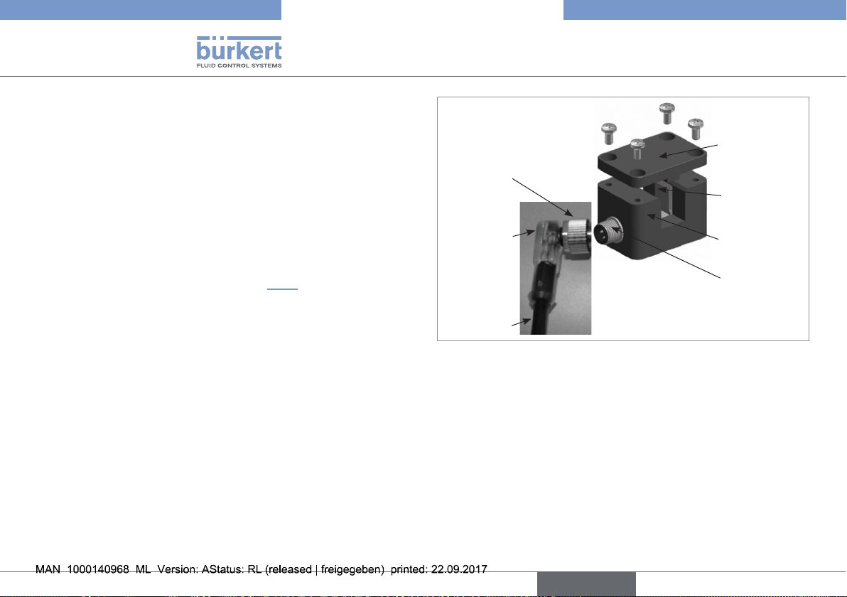
The electrolyte monitoring comprises (see Fig. 1):
• A sensor that contains two ultrasonic cells: an emitter and a
receiver;
• A screw-on cover that maintains the flexible hose in the sensor;
• A 5-m cable fitted with a right-angle M12 plug, that contains one
yellow and one green LEDs.
The electrolyte monitoring requires a power supply of 12-30 VDC and
has a PNP output which can be connected to an alarm. The electrolyte
monitoring is equipped with an M12 5-pin male fixed connector.
screw-on cover
right-angle
plug
LEDs
cable
Fig. 1: Exploded view of the electrolyte monitoring
ultrasonic cells
sensor
5-pin male
connector
5.2.2. Measuring principle
The sensor contains two ultrasonic cells: an emitter and a receiver.
The ultrasonic emitter transmits short high-frequency pulses. The
ultrasonic receiver analyzes the signal received:
• If the hose is filled with liquid, a part of the ultrasound is transferred by the emitter through the hose to the receiver. The yellow
LED is ON and the output is active.
• If the hose is empty or if there is a bubble, the part of the ultrasound received by the receiver is much lower. In that case, the
yellow LED of the connector goes out to indicate an error and the
8
English
Page 9
Type 8201
Technical data
output is set to zero.
5.3. Version available
The following version of the electrolyte monitoring is available. This
reference includes the ultrasonic module and a 5-meter long cable
including a 5-pin M12 plug.
Supply voltage Output Electrical
connection
12-30 VDC PNP
M12, 5-pin male
fixed connector
Ordering code
561533
6. TECHNICAL DATA
6.1. Conditions of use
Ambient temperature: +5 to +60°C (operating)
Protection rating: IP67
6.2. Conformity to standards and
directives
The conformity of the device to the EC directives is fulfilled by the
following standards:
• EMC: EN 61000-4-3, EN 61000-4-4, EN 61000-4-6, EN 55011
6.3. General technical data
6.3.1. Mechanical data
Component Material
Sensor/Cover POM
Ultrasonic Cell PPMA
Mold of the plug PUR
O-ring FKM
English
9
Page 10
Type 8201
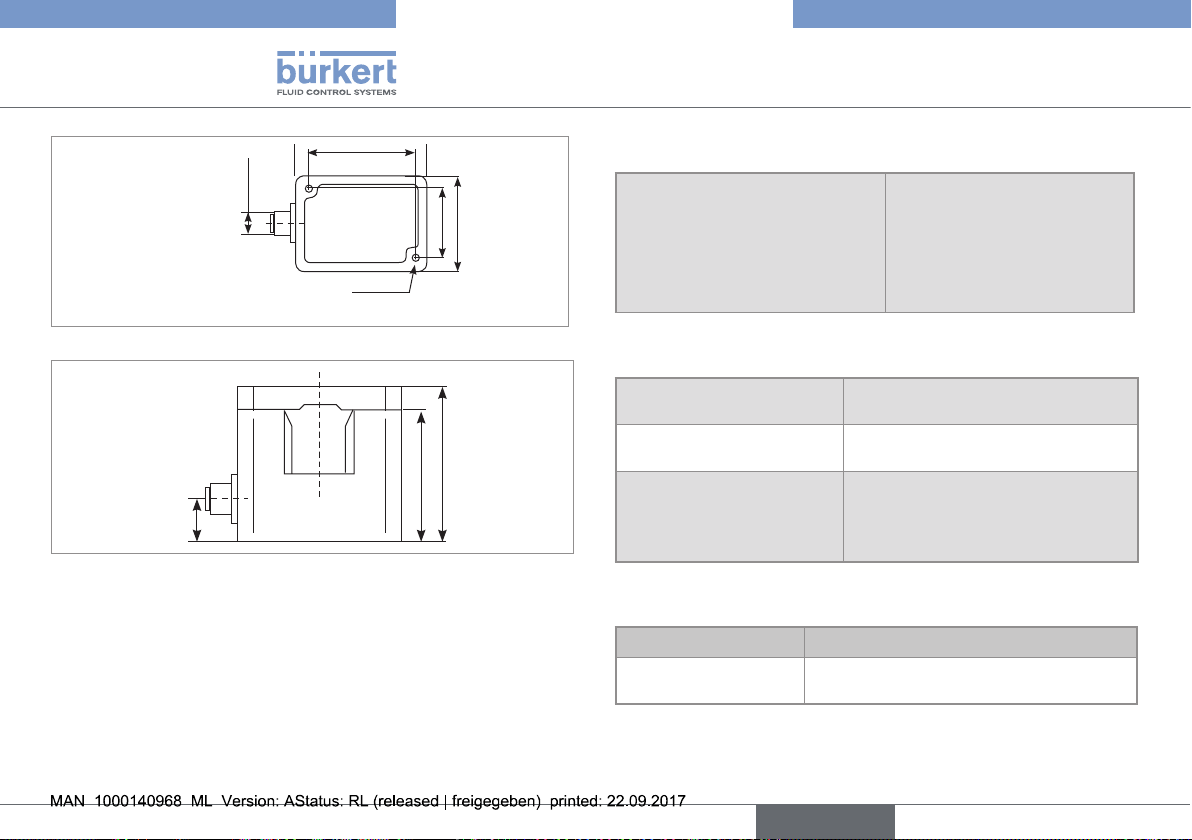
50
42
Technical data
6.3.2. General data
M12x1
27
35
Fastening holes M4, depth 8
Fig. 2: Dimensions of the electrolyte monitoring, top view [mm]
24
30
12
Fig. 3: Dimensions of the electrolyte monitoring, side view [mm]
Hose
• Material
• Length
• Outer diameter
• Optimal wall thickness
• PTFE
• 5 m max.
• 3.0 to 8.5 mm
• 10 to 20% of outer diameter
6.3.3. Electrical data
Power supply 12-30 VDC, filtered and regulated,
modulated max. 10%
Power max. 50 mA (without switching
current)
Current output
• Accuracy
• Response time
• ± 1% (0,16 mA)
• ≤ 0.5 ms
6.3.4. Electrical connections
Version Connection type
M12 5-pin male fixed
connector
A 5-meter long cable equipped with a
right-angle plug
10
English
Page 11
Type 8201
Installation and wiring
7. INSTALLATION AND WIRING
7.1. Safety instructions
DANGER
Risk of injury due to electrical voltage
• Before starting work, make sure that you switch off the supply
voltage and secure it to prevent restarting.
• Observe all applicable accident protection and safety guidelines
for electrical equipment.
WARNING
Risk of injury due to non-conforming installation.
• The electrical and fluid installation can only be carried out by
qualified and skilled staff with the appropriate tools.
• Respect the assembly instructions.
Risk of injury due to unintentional switch on of power supply
or uncontrolled restarting of the installation.
• Take appropriate measures to avoid unintentional activation of
the installation.
• Guarantee a set or controlled restarting of the process subsequent to the assembly of the device.
7.2. Installation on the electrolyte hose
DANGER
Risk of injury due to the nature of the fluid.
• Respect the regulations on accident prevention and safety relating to the use of aggressive fluids.
NOTE
The electrolyte monitoring may be irremediably damaged if
liquid is spraid between the ultrasonic cells.
• Always install a dry hose in the electrolyte monitoring.
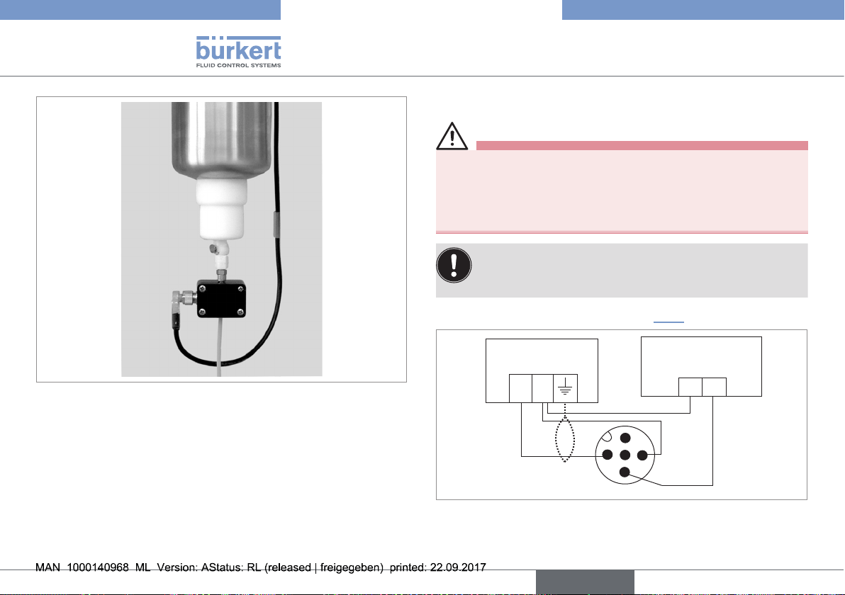
The electrolyte monitoring is installed on the electrolyte hose which
joins the electrolyte vessel to the pH sensor type 8201.
→ Clamp the sensor on the electrolyte hose as close as possible to
the output of the electrolyte vessel (see Fig. 4).
English
11
Page 12
Type 8201
Installation and wiring
7.3. Electrical wiring
DANGER
Risk of injury due to electrical voltage
• Before starting work, make sure that you switch off the supply
voltage and secure it to prevent restarting.
• Observe all applicable accident protection and safety guidelines
for electrical equipment.
• Use a high quality electrical power supply (filtered
and regulated).
• Make sure the installation is equipotential.
→ Connect the wires of the cable (see Fig. 5).
Fig. 4: Installation on the electrolyte hose
→ Screw the four screws of the cover onto the sensor in an
alternating pattern.
12
3
Alarm input
max. 200 mA
+ -
blue
black
Power supply
12-30 VDC
+-
brown
Fig. 5: Connection of the PNP output
2
1
5
4
→ If the cable is shielded, it should be grounded on the side of the
controlling unit.
English
Page 13
Type 8201
Electrolyte monitoring
green
yellow
Commissioning
8. COMMISSIONING
8.1. Safety instructions
WARNING
Danger due to non conforming commissioning.
Non conforming commissioning could lead to injuries and damage
the device and its surroundings.
• Before commissioning, make sure that the staff in charge have
read and fully understood the contents of the manual.
• In particular, observe the safety recommendations and intended
use.
• The device/installation must only be commissioned by suitably
trained staff.
Protect this device against electromagnetic interference,
ultraviolet rays and, when installed outdoors, the effects of
the climatic conditions.
8.2. Commissioning
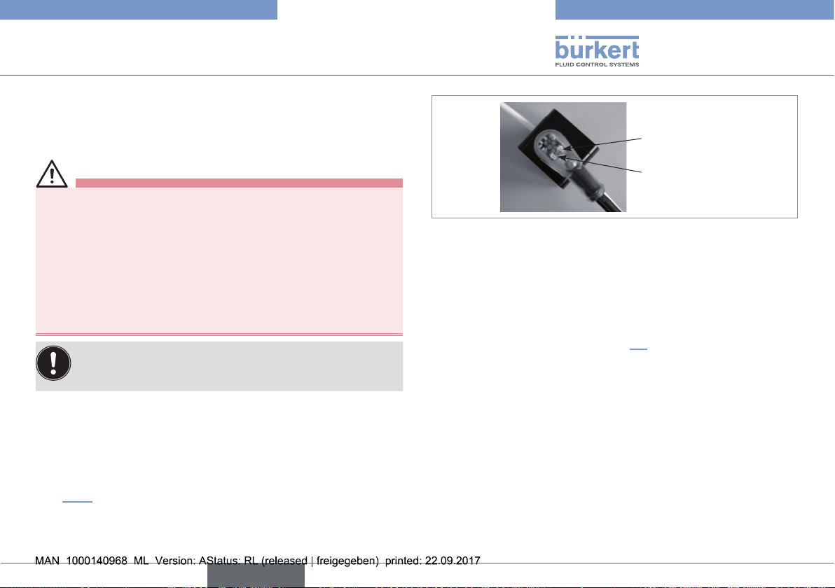
→ Plug the right-angle plug on the connector.
→ Tighten the plug nut.
The green LED of the connector lights up if the device is powered
(see Fig. 6).
green LED
yellow LED
Fig. 6: Position of the LEDs in the connector
8.3. Running
In normal running:
• the green LED is lit to ensure that the device is powered
• the yellow LED is on as long as electrolyte is in the bottle.
If the yellow LED goes off, see chap. 9.3.
English
13
Page 14
Type 8201
Troubleshooting
9. TROUBLESHOOTING
9.1. Safety instructions
DANGER
Risk of injury due to electrical discharge.
• Shut down and isolate the electrical power source before carrying out work on the system.
• Observe all applicable accident protection and safety regulations for electrical equipment.
Risk of injury due to the nature of the fluid.
• Respect the prevailing regulations on accident prevention and
safety relating to the use of aggressive fluids.
WARNING
Risk of injury due to non conforming maintenance.
• Maintenance must only be carried out by qualified and skilled
staff with the appropriate tools.
• Ensure that the restart of the installation is controlled after any
interventions.
NOTE
The pH measurement drifts if the reference electrode is
lacking electrolyte.
• Replace the electrolyte bottle (see pH sensor type 8201
manual) as soon as possible.
9.2. Disassembly of the electrolyte monitoring
CAUTION
Risk of injury due to whipping of the electrolyte hose.
• Hold the electrolyte hose while disassembling the electrolyte
monitoring.
→ Unscrew the four screws of the sensor cover.
→ Unclamp the sensor from the electrolyte hose.
9.3. In the event of problems
LEDs status Meaning Resolution
green LED is ON
and yellow LED
is OFF
Electrolyte
bottle
empty
→ Verify level of the electrolyte
bottle (see pH sensor type
8201 manual).
→ Replace it if necessary
(see pH sensor type 8201
manual).
Sensor
defective
→ If, despite presence of
electrolyte in the electrolyte
bottle, the fault persists,
contact your Bürkert retailer.
14
English
Page 15
Type 8201
Damage due to transport
Poor storage can damage the device.
Damage to the environment caused by products contami-
Packaging, Transport
10. PACKAGING, TRANSPORT
NOTE
Transport may damage an insufficiently protected device.
• Transport the device in shock-resistant packaging and away
from humidity and dirt.
• Do not expose the device to temperatures that may exceed the
admissible storage temperature range.
• Protect the electrical interfaces using protective plugs.
11. STORAGE
NOTE
• Store the device in a dry place away from dust.
• Storage temperature -20 to +70°C.
12. DISPOSAL OF THE PRODUCT
→
Dispose of the device and its packaging in an environmentallyfriendly way.
NOTE
nated by fluids.
• Keep to the existing provisions on the subject of waste disposal
and environmental protection.
Note:
Comply with the national and/or local regulations which
concern the area of waste disposal.
English
15
Page 16

Type 8201
16
English
Page 17

Typ 8201
Elektrolytüberwachung für Typ 8201
Inhaltsverzeichnis:
1. DIE BEDIENUNGSANLEITUNG ...............................................................5
1.1. Darstellungsmittel ..............................................................................5
1.2. Begriffsdefinition "Gerät" ................................................................5
2. BESTIMMUNGSGEMÄSSE VERWENDUNG ......................................6
2.1. Beschränkungen .................................................................................6
3. GRUNDLEGENDE SICHERHEITSHINWEISE ....................................6
4. ALLGEMEINE HINWEISE .............................................................................7
4.1. Herstelleradresse und internationale Kontaktadressen 7
4.2. Gewährleistung ....................................................................................7
4.3. Informationen im Internet ...............................................................7
5. BESCHREIBUNG .............................................................................................8
5.1. Vorgesehener Einsatzbereich ......................................................8
5.2. Allgemeine Beschreibung ..............................................................8
5.2.1. Aufbau ...................................................................................... 8
5.2.2. Messprinzip ............................................................................. 8
5.3. Verfügbare Version ............................................................................9
6. TECHNISCHE DATEN ...................................................................................9
6.1. Betriebsbedingungen .......................................................................9
6.2. Einhaltung von Normen und Richtlinien .................................9
6.3. Allgemeine Technische Daten .....................................................9
6.3.1. Mechanische Daten .............................................................. 9
6.3.2. Allgemeine Daten ................................................................10
6.3.3. Elektrische Daten ................................................................10
6.3.4. Elektrische Anschlüsse ......................................................10
7. INSTALLATION UND VERKABELUNG ...............................................11
7.1. Sicherheitshinweise ....................................................................... 11
7.2. Installation am Elektrolytschlauch ..........................................11
7.3. Elektrischer Anschluss ................................................................. 12
8. INBETRIEBNAHME ...................................................................................... 13
8.1. Sicherheitshinweise ....................................................................... 13
8.2. Inbetriebnahme ................................................................................. 13
8.3. Betrieb ...................................................................................................13
9. PROBLEMLÖSUNG .....................................................................................14
9.1. Sicherheitshinweise ....................................................................... 14
deutsch
3
Page 18

9.2. Demontage der Elektrolytüberwachung ..............................14
9.3. Störungsbehebung ......................................................................... 15
10. VERPACKUNG, TRANSPORT .............................................................. 15
11. ENTSORGUNG ............................................................................................16
Typ 8201
4
deutsch
Page 19

Typ 8201
Die Bedienungsanleitung
1. DIE BEDIENUNGSANLEITUNG
Die Bedienungsanleitung beschreibt den gesamten Lebenszyklus
des Gerätes. Bewahren Sie diese Anleitung so auf, dass sie für jeden
Benutzer zugänglich ist und jedem neuen Eigentümer des Gerätes
wieder zur Verfügung steht.
Die Bedienungsanleitung enthält wichtige Informationen zur
Sicherheit!
Das Nichtbeachten dieser Hinweise kann zu gefährlichen Situationen führen.
• Die Bedienungsanleitung muss gelesen und verstanden werden.
1.1. Darstellungsmittel
GEFAHR!
Warnt vor einer unmittelbaren Gefahr!
• Bei Nichteinhaltung sind Tod oder schwere Verletzungen die
Folge.
WARNUNG!
Warnt vor einer möglicherweise gefährlichen Situation!
• Bei Nichteinhaltung drohen schwere Verletzungen oder auch
der Tod.
VORSICHT!
Warnt vor einer möglichen Gefährdung!
• Nichtbeachtung kann mittelschwere oder leichte Verletzungen
zur Folge haben.
HINWEIS!
Warnt vor Sachschäden!
• Bei Nichtbeachtung kann das Gerät oder die Anlage beschädigt
werden.
bezeichnet wichtige Zusatzinformationen, Tipps und Empfehlungen, die für Ihre Sicherheit und die einwandfreie Funktion
des Gerätes wichtig sind.
verweist auf Informationen in dieser Bedienungsanleitung
oder in anderen Dokumentationen.
→ markiert einen Arbeitsschritt, den Sie ausführen müssen.
1.2. Begriffsdefinition "Gerät"
Der in dieser Anleitung verwendete Begriff "Gerät“ steht immer für
die Elektrolytüberwachung Typ 8201.
deutsch
5
Page 20

Typ 8201
Bestimmungsgemäße Verwendung
2. BESTIMMUNGSGEMÄSSE
VERWENDUNG
Bei nicht bestimmungsgemäßem Einsatz der Elektrolytüberwachung können Gefahren für Personen, Anlagen in der
Umgebung und die Umwelt entstehen.
• Die Elektrolytüberwachung dient ausschliesslich der Kontrolle
des Elektrolytinhalts in der Elektrolytflasche des pH-Sensors
Typ 8201.
• Schützen Sie das Gerät vor elektromagnetischen Störungen, U.V.-Bestrahlung und bei Außenanwendung vor
Witterungseinflüssen.
• Für den Einsatz sind die in den Vertragsdokumenten und der
Bedienungsanleitung spezifizierten zulässigen Daten, Betriebsund Einsatzbedingungen zu beachten.
• Voraussetzungen für den sicheren und einwandfreien Betrieb
sind sachgemäßer Transport, sachgemäße Lagerung und Installation sowie sorgfältige Bedienung und Instandhaltung.
• Setzen Sie das Gerät nur bestimmungsgemäß ein.
2.1. Beschränkungen
Beachten Sie bei der Ausfuhr des Gerätes gegebenenfalls bestehende
Beschränkungen.
3. GRUNDLEGENDE SICHERHEITSHINWEISE
Diese Sicherheitshinweise berücksichtigen keine:
• Zufälligkeiten und Ereignisse, die bei Montage, Betrieb und Wartung
der Geräte auftreten können.
• Ortsbezogene Sicherheitsbestimmungen, für deren Einhaltung, auch
in Bezug auf das Installations- und Wartungspersonal, der Betreiber
verantwortlich ist.
Gefahr durch elektrische Spannung!
Gefahr aufgrund der Art der Flüssigkeit!
Allgemeine Gefahrensituationen.
Zum Schutz vor Verletzungen ist zu beachten:
• Dass die Anlage nicht unbeabsichtigt betätigt werden kann.
• Installations- und Instandhaltungsarbeiten dürfen nur von autorisiertem Fachpersonal mit geeignetem Werkzeug durchgeführt werden.
• Nach einer Unterbrechung der elektrischen Versorgung ist ein
definierter oder kontrollierter Wiederanlauf des Prozesses zu
gewährleisten.
• Betreiben Sie das Gerät nur in einwandfreiem Zustand und
unter Beachtung der Bedienungsanleitung.
• Bei der Einsatzplanung und dem Betrieb des Gerätes die allgemeinen Regeln der Technik einhalten.
6
deutsch
Page 21

Typ 8201
Allgemeine hinweise
4. ALLGEMEINE HINWEISE
Allgemeine Gefahrensituationen.
Zum Schutz vor Verletzungen ist zu beachten:
• Dieses Gerät nicht in explosionsgefährdeten Bereichen einsetzen.
• Dieses Gerät nicht in einer Umgebung verwenden, die mit den
Werkstoffen, aus denen es besteht, inkompatibel ist.
• Nehmen Sie keine äußerlichen Veränderungen an den Gerätegehäusen vor. Lackieren Sie keinen Teil des Geräts.
HINWEIS!
Elektrostatisch gefährdete Bauelemente / Baugruppen!
• Das Gerät enthält elektronische Bauelemente, die gegen elektrostatische Entladung (ESD) empfindlich reagieren. Berührung
mit elektrostatisch aufgeladenen Personen oder Gegenständen
gefährdet diese Bauelemente. Im schlimmsten Fall werden sie
sofort zerstört oder fallen nach der Inbetriebnahme aus.
• Beachten Sie die Anforderungen nach EN 61340-5-1 und 5-2,
um die Möglichkeit eines Schadens durch schlagartige elektrostatische Entladung zu minimieren bzw. zu vermeiden!
• Achten Sie ebenso darauf, dass Sie elektronische Bauelemente
nicht bei anliegender Versorgungsspannung berühren!
4.1. Herstelleradresse und internationale Kontaktadressen
Sie können mit dem Hersteller des Gerätes unter folgender Adresse
Kontakt aufnehmen:
Bürkert SAS
Rue du Giessen
BP 21
67220 TRIEMBACH-AU-VAL
Die Kontaktadressen finden Sie auf den letzten Seiten dieser
Bedienungsanleitung.
Außerdem im Internet unter: www.burkert.com
4.2. Gewährleistung
Voraussetzung für die Gewährleistung ist der bestimmungsgemäße
Gebrauch des Gerätes unter Beachtung der im vorliegenden Handbuch
spezifizierten Einsatzbedingungen.
4.3. Informationen im Internet
Bedienungsanleitungen und Datenblätter zum Typ 8201 finden Sie im
Internet unter: www.buerkert.de
deutsch
7
Page 22

Typ 8201
Beschreibung
5. BESCHREIBUNG
5.1. Vorgesehener Einsatzbereich
Die Elektrolytüberwachung ist für die Kontrolle des Elektrolytinhalts in
der Elektrolytflasche des pH-Sensors Typ 8201 vorgesehen.
5.2. Allgemeine Beschreibung
5.2.1. Aufbau
Zur Elektrolytüberwachung gehören (siehe Bild 1):
• Ein Sensor, der zwei Ultraschallzellen enthält, einen Sender und
einen Empfänger;
• Ein Deckel mit 4 Schrauben, der den Schlauch im Sensor hält;
• Ein 5 m langes Kabel mit einer abgewinkelten M12-Buchse, die
eine gelbe und eine grüne Leuchtdiode besitzt.
Die Elektrolytüberwachung erfordert eine 12-30 VDC Stromversorgung
und hat einen PNP-Ausgang, der als Alarmausgang genutzt werden
kann. Die Elektrolytüberwachung ist mit einem 5-poligen M12Gerätestecker ausgestattet.
Deckel mit Schrauben
abgewinkelte
Buchse
Ultraschall-
Leuchtdioden
5-poliger
Stecker
Kabel
Bild 1: Explosionszeichnung der Elektrolytüberwachung
zellen
Sensor
5.2.2. Messprinzip
Der Sensor enthält zwei Ultraschallzellen, einen Sender und einen
Empfänger. Der Ultraschallsender sendet kurze, hochfrequente
Impulse. Der Ultraschallempfänger analysiert das empfangene
Signal:
• Wenn der Schlauch mit Flüssigkeit gefüllt ist, wird ein Teil des
Ultraschalls vom Sender durch den Schlauch zum Empfänger
8
deutsch
Page 23

Typ 8201
Technische Daten
übertragen. Die gelbe Leuchtdiode leuchtet und der Ausgang ist
aktiv.
• Wenn der Schlauch leer ist oder eine Gasblase enthält, ist der
Anteil des vom Empfänger empfangenen Ultraschalls viel geringer.
Die gelbe Leuchtdiode ist aus und der Ausgang ist gleich Null.
5.3. Verfügbare Version
Die folgende Version der Elektrolytüberwachung ist erhältlich. Diese
Referenz umfasst das Ultraschallmodul und ein 5 Meter langes
Kabel mit einer 5-poligen M12-Buchse.
Versorgungsspannung
12-30 VDC PNP
Ausgang Elektrischer
Anschluss
5-poliger M12-
Stecker, starr
Bestellnummer
561533
6. TECHNISCHE DATEN
6.1. Betriebsbedingungen
Umgebungstemperatur: +5 bis +60 °C (Betrieb)
Schutzart: IP67
6.2. Einhaltung von Normen und Richtlinien
Durch folgende Normen wird die Konformität mit den EG-Richtlinien
erfüllt:
• EMC: EN 61000-4-3, EN 61000-4-4, EN 61000-4-6, EN 55011
6.3. Allgemeine Technische Daten
6.3.1. Mechanische Daten
Element Werkstoff
Sensor/Deckel POM
Ultraschallzelle PPMA
Steckergehäuse PUR
O-ring FKM
deutsch
9
Page 24

Typ 8201
50
42
Technische Daten
6.3.2. Allgemeine Daten
M12x1
27
35
Befestigungslöcher M4, Tiefe 8
Bild 2: Abmessungen der Elektrolytüberwachung, Draufsicht [mm]
24
30
12
Bild 3: Abmessungen der Elektrolytüberwachung, Seitenansicht
[mm]
Schlauch
• Werkstoff
• Länge
• Außendurchmesser
• Optimale Wanddicke
• PTFE
• max. 5 m
• 3,0 bis 8,5 mm
• 10 bis 20 % des Außendurchmessers
6.3.3. Elektrische Daten
Stromversorgung 12-30 VDC, gefiltert und geregelt,
Modulation max. 10 %
Stromaufnahme max. 50 mA (ohne Schaltstrom)
Stromausgang
• Genauigkeit
• Reaktionszeit
• ± 1% (0,16 mA)
• ≤ 0.5 ms
6.3.4. Elektrische Anschlüsse
Version Anschlusstyp
5-poliger M12-Stecker Ein 5 Meter langes Kabel mit rechtwink-
liger Buchse
10
deutsch
Page 25

Typ 8201
Installation und Verkabelung
7. INSTALLATION UND
VERKABELUNG
7.1. Sicherheitshinweise
GEFAHR!
Verletzungsgefahr durch Stromschlag!
• Schalten Sie vor Beginn der Arbeiten in jedem Fall die Spannung ab und sichern Sie diese vor Wiedereinschalten!
• Beachten Sie die Unfallverhütungs- und Sicherheitsbestimmungen für elektrische Geräte!
WARNUNG!
Verletzungsgefahr bei unsachgemäßer Installation!
• Fluidische und elektrische Installationen dürfen nur durch autorisiertes Fachpersonal und mit geeignetem Werkzeug durchgeführt werden!
• Beachten Sie die Montageanweisungen des verwendeten
Fittings.
Verletzungsgefahr durch ungewolltes Einschalten der Anlage
und unkontrollierten Wiederanlauf!
• Anlage vor unbeabsichtigtem Betätigen sichern.
• Nach der Installation einen kontrollierten Wiederanlauf
gewährleisten.
7.2. Installation am Elektrolytschlauch
GEFAHR!
Verletzungsgefahr aufgrund der Art der Flüssigkeit.
• Beachten Sie die Regeln, die auf dem Gebiet der Unfallverhütung
und der Sicherheit in Kraft sind und die sich auf die Verwendung
aggressiver Flüssigkeiten beziehen.
HINWEIS!
Die Elektrolytüberwachung kann irreversibel beschädigt
werden, wenn Flüssigkeit zwischen die Ultraschallzellen
gelangt.
• Immer einen trockenen Schlauch in der Elektrolytüberwachung
installieren.
Die Elektrolytüberwachung wird an dem Elektrolytschlauch installiert,
der den Elektrolytbehälter mit dem pH-Sensor Typ 8201 verbindet.
→ Den Sensor so an den Elektrolytschlauch klemmen, dass er sich
so dicht wie möglich am Auslass des Elektrolytbehälters befindet
(siehe Bild 4).
deutsch
11
Page 26

Typ 8201
Installation und Verkabelung
7.3. Elektrischer Anschluss
GEFAHR!
Verletzungsgefahr durch Stromschlag!
• Schalten Sie vor Beginn der Arbeiten in jedem Fall die Spannung ab und sichern Sie diese vor Wiedereinschalten!
• Beachten Sie geltende Unfallverhütungs- und Sicherheitsbestimmungen für elektrische Geräte!
• Verwenden Sie eine hochwertige (gefilterte und gere-
gelte) Stromversorgung.
• Den Potentialausgleich der Installation gewährleisten.
→ Die Leiter des Kabels anschließen (siehe Bild 5).
Bild 4: Installation am Elektrolytschlauch
→ Die vier Schrauben des Deckels über Kreuz an den Sensor
schrauben.
12
deutsch
3
4
Alarmeingang
max. 200 mA
+ -
blau
schwarz
Stromversorgung
12-30 VDC
+-
braun
Bild 5: Anschluss des PNP-Ausgangs
2
1
5
→ Falls es sich um ein abgeschirmtes Kabel handelt, sollte es auf
der Seite der Steuereinheit geerdet werden.
Page 27

Electrolyte monitoring
green
yellow
Typ 8201
Inbetriebnahme
8. INBETRIEBNAHME
8.1. Sicherheitshinweise
WARNUNG!
Verletzungsgefahr bei unsachgemäßer Inbetriebnahme!
Nicht sachgemäßer Betrieb kann zu Verletzungen sowie Schäden
am Gerät und seiner Umgebung führen.
• Vor der Inbetriebnahme muss gewährleistet sein, dass der Inhalt
der Bedienungsanleitung dem Bedienungspersonal bekannt ist
und vollständig verstanden wurde.
• Besonders zu beachten sind die Sicherheitshinweise und die
bestimmungsgemäße Verwendung.
• Das Gerät/die Anlage darf nur durch ausreichend geschultes
Personal in Betrieb genommen werden.
HINWEIS!
Gefahr der Beschädigung des Geräts durch die Umgebung!
• Schützen Sie das Gerät vor elektromagnetischen Störungen, U.V.-Bestrahlung und bei Außenanwendung vor
Witterungseinflüssen.
8.2. Inbetriebnahme
→ Die rechtwinklige Steckbuchse an den Gerätestecker stecken.
→ Die Überwurfmutter festziehen.
Die grüne Leuchtdiode der Buchse leuchtet auf, wenn das Gerät mit
Strom versorgt wird (siehe Bild 6).
grüne Leuchtdiode
gelbe Leuchtdiode
Bild 6: Position der Leuchtdioden in der Buchse
8.3. Betrieb
Im Normalbetrieb:
• Die grüne Leuchtdiode leuchtet, um sicherzustellen, dass das
Gerät mit Strom versorgt ist.
• Die gelbe Leuchtdiode leuchtet, solange Elektrolyt in der Flasche
ist.
Wenn die gelbe Leuchtdiode aus ist: Siehe Kap. 9.3.
deutsch
13
Page 28

Typ 8201
Problemlösung
9. PROBLEMLÖSUNG
9.1. Sicherheitshinweise
GEFAHR!
Verletzungsgefahr durch Stromschlag!
• Schalten Sie vor Beginn der Arbeiten in jedem Fall die Spannung ab, und sichern Sie diese vor Wiedereinschalten!
• Beachten Sie geltende Unfallverhütungs- und Sicherheitsbestimmungen für elektrische Geräte!
Verletzungsgefahr aufgrund der Art der Flüssigkeit.
• Beachten Sie die Regeln, die auf dem Gebiet der Unfallverhütung
und der Sicherheit in Kraft sind und die sich auf die Verwendung
aggressiver Flüssigkeiten beziehen.
WARNUNG!
Gefahr durch unsachgemäße Wartungsarbeiten!
• Wartungsarbeiten dürfen nur durch autorisiertes Fachpersonal
und mit geeignetem Werkzeug durchgefürht werden!
• Nach jedem Eingriff an der Anlage einen kontrollierten Wiederanlauf gewährleisten.
HINWEIS!
Die pH-Messwerte verschieben sich, wenn die Referenzelektrode zu wenig Elektrolyt hat.
• Ersetzen Sie die Elektrolytflasche (siehe Bedienungsanleitung
des pH-Sensors Typ 8201) so bald wie möglich.
9.2. Demontage der Elektrolytüberwachung
VORSICHT!
Verletzungsgefahr durch peitschenden Elektrolytschlauch.
• Halten Sie den Elektrolytschlauch fest, während die Elektrolytüberwachung demontiert wird.
→ Lösen Sie die vier Schrauben des Sensordeckels.
→ Ziehen Sie den Sensor vom Elektrolytschlauch ab.
14
deutsch
Page 29

Typ 8201
Transportschäden!
Falsche Lagerung kann Schäden am Gerät verursachen!
Verpackung, Transport
9.3. Störungsbehebung
Status der
Leuchtdioden
grüne Leuchtdiode leuchtet
und gelbe Leuchtdiode ist aus
Bedeu
tung
Elektrolytflasche
leer
Sensor
defekt
Maßnahme
→ Füllstand der Elektrolyt-
flasche überprüfen (siehe
Bedienungsanleitung des
pH-Sensors Typ 8201).
→ Ersetzen, falls erforderlich
(siehe Bedienungsanleitung
des pH-Sensors Typ 8201).
→ Falls der Fehler trotz Vorhan-
densein von Elektrolyt in der
Elektrolytflasche bestehen
bleibt, kontaktieren Sie bitte
Ihren Bürkert Händler.
10. VERPACKUNG, TRANSPORT
VORSICHT!
Ein unzureichend geschütztes Gerät kann durch den Transport
beschädigt werden.
• Transportieren Sie das Gerät vor Nässe und Schmutz geschützt
in einer stoßfesten Verpackung.
• Das Gerät keinen Temperaturen außerhalb des zulässigen Temperaturbereichs für die Lagerung aussetzen.
• Verschließen Sie die elektrischen Schnittstellen mit Schutzkappen vor Beschädigungen.
11. LAGERUNG
VORSICHT!
• Lagern Sie das Gerät trocken und staubfrei!
• Lagerungstemperatur: -20 bis +70 °C.
deutsch
15
Page 30

12. ENTSORGUNG
Umweltschäden durch Teile, die durch Flüssigkeiten kontami-
→
Entsorgen Sie das Gerät und die Verpackung umweltgerecht.
VORSICHT!
niert wurden!
• Geltende Entsorgungsvorschriften und Umweltbestimmungen
einhalten!
Hinweis:
Beachten Sie die nationalen Abfallbeseitigungsvorschriften.
Typ 8201
Entsorgung
16
deutsch
Page 31

Typ 8201
deutsch
17
Page 32

Typ 8201
18
deutsch
Page 33

Type 8201
Détecteur de niveau d'électrolyte pour le Type 8201
Sommaire :
1. A PROPOS DE CE MANUEL ......................................................................5
1.1. Symboles utilisés ................................................................................5
1.2. Définition du terme „appareil“ ......................................................5
2. UTILISATION CONFORME..........................................................................6
2.1. Restrictions ............................................................................................6
3. CONSIGNES DE SÉCURITÉ DE BASE ................................................6
4. INFORMATIONS GÉNÉRALES ..................................................................7
4.1. Adresse du fabricant et contacts internationaux ...............7
4.2. Conditions de garantie .....................................................................7
4.3. Informations sur internet ................................................................7
5. DESCRIPTION ...................................................................................................8
5.1. Secteur d'application ........................................................................8
5.2. Description générale .........................................................................8
5.2.1. Construction ........................................................................... 8
5.2.2. Principe de mesure ............................................................... 8
5.3. Version disponible ..............................................................................9
6. CARACTÉRISTIQUES TECHNIQUES ...................................................9
6.1. Conditions d'utilisation .....................................................................9
6.2. Conformité aux normes ...................................................................9
6.3. Caractéristiques techniques générales ..................................9
6.3.1. Caractéristiques mécaniques ............................................. 9
6.3.2. Caractéristiques générales ...............................................10
6.3.3. Caractéristiques électriques .............................................10
6.3.4. Raccordements électriques ..............................................10
7. INSTALLATION ET CÂBLAGE ÉLECTRIQUE .................................. 11
7.1. Consignes de sécurité .................................................................. 11
7.2. Installation sur le tube flexible .................................................11
7.3. Câblage électrique .......................................................................... 12
8. MISE EN SERVICE ....................................................................................... 13
8.1. Consignes de sécurité .................................................................. 13
8.2. Mise en service ................................................................................. 13
8.3. Fonctionnement ................................................................................ 13
9. MAINTENANCE ET DÉPANNAGE ........................................................ 14
9.1. Consignes de sécurité .................................................................. 14
français
3
Page 34

9.2. Démonter le détecteur de niveau ...........................................14
9.3. En cas de problème .......................................................................15
10. EMBALLAGE ET TRANSPORT ............................................................15
11. ELIMINATION DE L'APPAREIL .............................................................16
Type 8201
4
français
Page 35

Type 8201
A propos de ce manuel
1. A PROPOS DE CE MANUEL
Ce manuel décrit le cycle de vie complet de l'appareil. Conservez-le
de sorte qu'il soit accessible à tout utilisateur et à disposition de tout
nouveau propriétaire.
Ce manuel contient des informations importantes relatives à
la sécurité.
Le non-respect de ces consignes peut entraîner des situations
dangereuses.
• Ce manuel doit être lu et compris.
1.1. Symboles utilisés
DANGER
Met en garde contre un danger imminent.
• Son non-respect peut entraîner la mort ou de graves blessures.
AVERTISSEMENT
Met en garde contre une situation éventuellement
dangereuse.
• Son non-respect peut entraîner de graves blessures, voire la
mort.
ATTENTION
Met en garde contre un risque éventuel.
• Son non-respect peut entraîner des blessures légères ou de
gravité moyenne.
REMARQUE
Met en garde contre des dommages matériels.
• Son non-respect peut entraîner des dommages sur l'appareil ou
l'installation.
désigne des informations supplémentaires, des conseils ou
des recommandations importants pour votre sécurité et le
fonctionnement parfait de l‘appareil.
renvoie à des informations contenues dans ce manuel ou
dans d'autres documents.
→ indique une opération à effectuer.
1.2. Définition du terme „appareil“
→ Dans ce manuel d‘utilisation, le terme „appareil“ désigne toujours
le détecteur du niveau d'électrolyte Type 8201.
français
5
Page 36

Type 8201
Utilisation conforme
2. UTILISATION CONFORME
L'utilisation non conforme du détecteur de niveau d'électrolyte peut présenter des dangers pour les personnes, les
installations proches et l'environnement.
• Le détecteur de niveau d'électrolyte est destiné au contrôle du
niveau du réservoir d'électrolyte du capteur de pH type 8201.
• Protéger cet appareil contre les perturbations
électromagnétiques, les rayons ultraviolets et, lorsqu'il est installé à l'extérieur, des effets des conditions climatiques.
• Utiliser cet appareil conformément aux caractéristiques et
conditions de mise en service et d'utilisation indiquées dans les
documents contractuels et dans le manuel utilisateur.
• L'utilisation en toute sécurité et sans problème de l'appareil
repose sur un transport, un stockage et une installation corrects
ainsi que sur une utilisation et une maintenance effectuées avec
soin.
• Veiller à toujours utiliser cet appareil de façon conforme.
2.1. Restrictions
Respecter les restrictions éventuelles lorsque l'appareil est exporté.
3. CONSIGNES DE SÉCURITÉ DE BASE
Ces consignes de sécurité ne tiennent pas compte :
• des imprévus pouvant survenir lors de l'assemblage, de l'utilisation
et de l'entretien des appareils.
• des prescriptions de sécurité locales que l'exploitant est tenu de faire
respecter par le personnel chargé de l'assemblage et de l'entretien.
Danger dû à la tension électrique.
Danger dû à la nature du fluide.
Situations dangereuses diverses
Pour éviter toute blessure, veiller à :
• empêcher toute mise sous tension involontaire de l'installation.
• ce que les travaux d'installation et de maintenance soient
effectués par du personnel qualifié et habilité, disposant des
outils appropriés.
• garantir un redémarrage défini et contrôlé du process, après
une coupure de l'alimentation électrique.
• n'utiliser l'appareil qu'en parfait état et en tenant compte des
indications du manuel utilisateur.
• respecter les règles générales de la technique lors de la
planification et de l'utilisation de l'appareil.
6
français
Page 37

Type 8201
Informations générales
4. INFORMATIONS GÉNÉRALES
Situations dangereuses diverses
Pour éviter toute blessure, veiller à :
• Ne pas utiliser cet appareil dans une atmosphère explosible.
• Ne pas utiliser cet appareil dans un environnement incompatible
avec les matériaux qui le composent.
• N'apporter aucune modification extérieure au corps. Ne peindre
ni laquer aucune partie de l'appareil.
REMARQUE
Eléments / Composants sensibles aux décharges électrostatiques
• Cet appareil contient des composants électroniques sensibles
aux décharges électrostatiques. Ils peuvent être endommagés
lorsqu'ils sont touchés par une personne ou un objet chargé
électrostatiquement. Dans le pire des cas, ils sont détruits
instantanément ou tombent en panne sitôt effectuée la mise en
route.
• Pour réduire au minimum voire éviter tout dommage dû à une
décharge électrostatique, prenez toutes les précautions décrites
dans les normes EN 61340-5-1 et 5-2.
• Veiller également à ne pas toucher les composants électriques
sous tension.
4.1. Adresse du fabricant et contacts internationaux
Le fabricant de l‘appareil peut être contacté à l‘adresse suivante :
Bürkert SAS
Rue du Giessen
BP 21
67220 TRIEMBACH-AU-VAL
Les adresses des filiales internationales sont disponibles sur internet
sous : www.burkert.com
4.2. Conditions de garantie
La condition pour bénéficier de la garantie légale est l’utilisation
conforme du détecteur de niveau d'électrolyte type 8201 dans
le respect des conditions d’utilisation spécifiées dans le présent
manuel utilisateur.
4.3. Informations sur internet
Retrouvez sur internet les manuels utilisateur et les fiches techniques relatifs au type 8201 sous : www.burkert.fr
français
7
Page 38

5. DESCRIPTION
Type 8201
Description
5.1. Secteur d'application
Le détecteur de niveau d'électrolyte est destiné au contrôle du niveau
du réservoir d'électrolyte du capteur de pH type 8201.
5.2. Description générale
5.2.1. Construction
Le détecteur de niveau d'électrolyte se compose :
• d'un capteur qui contient deux cellules à ultrasons : un émetteur et
un récepteur ;
• d'un couvercle à vis qui maintient le flexible dans le capteur ;
• d'un câble de 5 m équipé d'un connecteur coudé M12, qui contient
un voyant jaune et un voyant vert.
Le détecteur de niveau d'électrolyte nécessite une alimentation de
12-30 VDC et possède une sortie PNP qui peut être connectée à
un système d'alarme.
Le détecteur de niveau d'électrolyte est équipé d'une embase M12
mâle à 5 broches.
couvercle à vis
connecteur
voyants
câble
Fig. 1 : Vue éclatée du détecteur de niveau
cellules à
ultrasons
capteur
embase mâle à
5 broches
5.2.2. Principe de mesure
Le capteur contient deux cellules à ultrasons : un émetteur et un
récepteur. L'émetteur émet de brèves impulsions haute-fréquence.
Le récepteur analyse le signal reçu :
• Si le tube flexible est rempli de liquide, une portion d'ultrasons est
transmis de l'émetteur au récepteur à travers le flexible. Le voyant
jaune est allumé et la sortie est active.
8
français
Page 39

Type 8201
Caractéristiques techniques
• Si le tube flexible est vide ou s'il contient une bulle, la quantité
d'ultrasons reçue par le récepteur est plus faible. Le voyant est
éteint et la sortie est à zéro.
5.3. Version disponible
La version suivante du détecteur de niveau d'électrolyte est disponible.
Cette référence comprend le module à ultrasons et le câble de 5m
équipé d'un connecteur coudé femelle M12 à 5 broches.
Tension
d'alimentation
12-30 VDC PNP
Sortie Raccordement
électrique
embase M12 mâle à 5
broches
Référence de
commande
561533
6. CARACTÉRISTIQUES
TECHNIQUES
6.1. Conditions d'utilisation
Température ambiante : +5...+60 °C (en fonctionnement)
Indice de protection : IP67
6.2. Conformité aux normes
La conformité de l'appareil aux directives CE est respectée par les
normes suivantes :
• CEM : EN 61000-4-3, EN 61000-4-4, EN 61000-4-6, EN 55011
6.3. Caractéristiques techniques générales
6.3.1. Caractéristiques mécaniques
Elément Matériau
Capteur / couvercle POM
Cellules à ultrasons PPMA
Moulage du connecteur PUR
français
Joint du connecteur
femelle
FKM
9
Page 40

Type 8201
50
42
Caractéristiques techniques
6.3.2. Caractéristiques générales
M12x1
27
35
Fixation M4, profondeur 8
Fig. 2 : Dimensions du détecteur de niveau d'électrolyte, vue de
dessus [mm].
24
30
12
Fig. 3 : Dimensions du détecteur de niveau d'électrolyte, vue de
profil [mm]
Tube flexible
• Matériau
• Longueur
• Diamètre externe
• Epaisseur optimale de
• PTFE
• 5m. max.
• 3.0...8.5 mm
• 10 à 20 % du diamètre externe
paroi
6.3.3. Caractéristiques électriques
Alimentation 12-30 VDC, filtrée et régulée, modu-
lation max. 10%
Courant max. 50 mA (sans courant d'interruption)
Sortie courant
• Précision
• Temps de réponse
• ± 1% (0,16 mA)
• ≤ 0.5 ms
(10%-90%)
6.3.4. Raccordements électriques
Version Type de raccordement
Embase M12 mâle à 5
broches
Câble de 5 m équipé d'un connecteur
femelle M12
10
français
Page 41

Type 8201
Installation et câblage électrique
7. INSTALLATION ET CÂBLAGE
ÉLECTRIQUE
7.1. Consignes de sécurité
DANGER
Risque de blessure par décharge électrique.
• Couper et consigner l'alimentation électrique avant d'intervenir
sur l'installation.
• Respecter la règlementation en vigueur en matière de prévention des accidents et de sécurité relative aux appareils
électriques.
AVERTISSEMENT
Risque de blessure dû à une installation non conforme.
• L'installation électrique et fluidique ne peut être effectuée
que par du personnel habilité et qualifié, disposant des outils
appropriés.
• Respecter les consignes de montage du raccord utilisé.
Risque de blessure dû à une mise sous tension involontaire
de l'installation et à un redémarrage incontrôlé.
• Protéger l'installation contre toute mise sous tension
involontaire.
• Garantir un redémarrage contrôlé de l'installation, après assemblage de l'appareil.
7.2. Installation sur le tube flexible
DANGER
Risque de blessure dû à la nature du fluide.
• Respecter la règlementation en vigueur en matière de prévention des accidents et de sécurité relative à l'utilisation de fluides
agressifs.
REMARQUE
Le détecteur de niveau peut être endommagé irrémédiablement si du liquide est projeté sur ou entre les cellules à
ultrasons.
• Toujours installer un tube flexible sec dans le détecteur de
niveau d'électrolyte.
Le détecteur de niveau d'électrolyte est installé sur le tube flexible
qui relie le réservoir d'électrolyte au capteur de pH type 8201.
→ Fixer le capteur sur le tube flexible aussi près que possible de la
sortie du réservoir d'électrolyte (voir Fig. 4).
français
11
Page 42

Type 8201
Installation et câblage électrique
7.3. Câblage électrique
DANGER
Risque de blessure par décharge électrique
• Couper et consigner l'alimentation électrique avant d'intervenir
sur l'installation.
• Respecter la règlementation en vigueur en matière de prévention des accidents et de sécurité relative aux appareils
électriques.
• Utiliser une alimentation électrique de qualité (filtrée
et régulée).
• Garantir l'équipotentialité de l'installation.
→ Connecter les fils du câble (voir Fig. 5).
Fig. 4 : Installation du détecteur de niveau d'électrolyte sur le
tube flexible.
→ Visser en croix les quatre vis du couvercle sur le capteur.
12
3
4
Entrée alarme
max. 200 mA
+ -
bleu
noir
Alimentation
12-30 VDC
+-
2
marron
Fig. 5 : Raccordement de la sortie PNP
1
5
→ Si le câble est blindé, relier le blindage à la terre de l'alimentation
(voir Fig. 5).
français
Page 43

Type 8201
Electrolyte monitoring
green
yellow
Mise en service
8. MISE EN SERVICE
8.1. Consignes de sécurité
AVERTISSEMENT
Risque de blessure dû à une mise en service non conforme.
La mise en service non conforme peut entrainer des blessures et
endommager l'appareil et son environnement.
• S'assurer, avant la mise en service, que le personnel qui en est
chargé a lu et parfaitement compris le contenu de ce manuel.
• Respecter en particulier les consignes de sécurité et l'utilisation
conforme.
• L'appareil / l'installation ne doit être mis(e) en service que par
du personnel suffisamment formé.
Protéger l’appareil contre les perturbations électromagnétiques, les rayons ultraviolets et, lorsqu’il est installé à l’extérieur, des effets des conditions climatiques.
8.2. Mise en service
→ Brancher le connecteur du câble sur l'embase.
→ Visser l'écrou du connecteur du câble.
Le voyant vert s'allume si l'appareil est alimenté (voir Fig. 6).
voyant vert
voyant jaune
Fig. 6 : Emplacement des voyants du connecteur
8.3. Fonctionnement
En fonctionnement normal :
• le voyant vert est allumé pour garantir que l'appareil est alimenté ;
• le voyant jaune est allumé lorsque le réservoir contient de
l'électrolyte.
Si le voyant jaune est éteint, voir chap. 9.3.
français
13
Page 44

Type 8201
Maintenance et dépannage
9. MAINTENANCE ET
DÉPANNAGE
9.1. Consignes de sécurité
DANGER
Risque de blessure par décharge électrique.
• Couper et consigner l'alimentation électrique avant d'intervenir
sur l'installation.
• Respecter la règlementation en vigueur en matière de
prévention des accidents et de sécurité relative aux appareils
électriques.
Risque de blessure dû à la nature du fluide.
• Respecter la règlementation en vigueur en matière de prévention
des accidents et de sécurité relative à l'utilisation de fluides
agressifs.
AVERTISSEMENT
Danger dû à une maintenance non conforme.
• Ces travaux doivent être effectués uniquement par du personnel
qualifié et habilité, disposant des outils appropriés.
• Après toute coupure de l'alimentation électrique, garantir un
redémarrage défini ou contrôlé du process.
REMARQUE
La mesure du pH dérive si l'électrode de référence manque
d'électrolyte.
• Remplacer le réservoir d'électrolyte (voir manuel du capteur de
pH type 8201) aussi vite que possible.
9.2. Démonter le détecteur de niveau
ATTENTION
Risque de blessure dû à un coup de fouet du tube flexible.
• Maintenir le tube flexible pendant le démontage du détecteur de
niveau d'électrolyte.
→ Dévisser les quatre vis du couvercle du capteur.
→ Désolidariser le capteur du tube flexible.
14
français
Page 45

Type 8201
Emballage et transport
9.3. En cas de problème
Etat des voyants
lumineux
voyant vert allumé
et voyant jaune
éteint
Signification Résolution
Réservoir d'électrolyte vide
Capteur
défectueux
→ Vérifier le niveau du
réservoir d'électrolyte
(voir manuel du capteur
de pH type 8201).
→ Remplacer le réservoir
si nécessaire (voir
manuel capteur de pH
type 8201).
→ Si malgré la présence
d'électrolyte dans le
réservoir, le défaut persiste, contacter votre
revendeur Bürkert.
10. EMBALLAGE ET TRANSPORT
REMARQUE
Dommages dus au transport
Le transport peut endommager un appareil insuffisamment
protégé.
• Transporter l'appareil dans un emballage résistant aux chocs, à
l'abri de l'humidité et des impuretés.
• Eviter les effets de la chaleur et du froid pouvant entrainer le
dépassement de la plage de température de stockage.
• Protéger les interfaces électriques à l'aide de bouchons de
protection.
11. STOCKAGE
REMARQUE
Un mauvais stockage peut endommager l'appareil.
• Stocker l'appareil dans un endroit sec et à l'abri de la poussière.
• Température de stockage -20 à +70 °C.
français
15
Page 46

12. ELIMINATION DE L'APPAREIL
→
Eliminer l'appareil et l'emballage dans le respect de l'environnement.
REMARQUE
Dommages à l'environnement causés par des pièces contaminées par des fluides.
• Respecter les prescriptions en vigueur en matière d'élimination
des déchets et de protection de l'environnement.
Remarque
Respecter les prescriptions nationales en matière d'élimination des déchets .
Type 8201
Elimination de l'appareil
16
français
Page 47

Page 48

www.burkert.com
 Loading...