

Burkert 8200 Series Operating Instructions Manual

Type 8200
Direct Welding
Sondenhalter für direkte Schweißung
Support à souder
Operating Instructions
Bedienungsanleitung
Manuel d‘utilisation

We reserve the right to make technical changes without notice.
Technische Änderungen vorbehalten.
Sous réserve de modifications techniques.
© 2013 Bürkert SAS
Operating Instructions 1304/0_EU-ML_00564992_Original_FR

Type 8200
Contents
1. ABOUT THIS MANUAL .................................................................................4
1.1. Symbols used .......................................................................................4
1.2. Definition of the word "holder" ....................................................4
2. INTENDED USE ................................................................................................5
3. BASIC SAFETY INFORMATION ....................................................................5
4. GENERAL INFORMATION ...........................................................................6
4.1. International contacts .......................................................................6
4.2. Warranty conditions ...........................................................................6
4.3. Information on the Internet ............................................................6
5. DESCRIPTION ...................................................................................................7
5.1. Area of application .............................................................................7
5.2. Available version .................................................................................7
5.3. General description ...........................................................................7
6. TECHNICAL DATA ...........................................................................................8
6.1. Conditions of use ................................................................................8
6.2. Dimensions ............................................................................................8
6.3. Materials ..................................................................................................9
7. INSTALLATION, COMMISSIONING ..................................................................9
7.1. Safety instructions..............................................................................9
7.2. Installation onto the pipe ............................................................. 10
7.3. Inserting the probe ..........................................................................11
7.3.1. Operating mode ..................................................................11
7.3.2. The pressure evacuation holes feature .........................12
8. MAINTENANCE AND TROUBLESHOOTING .................................. 12
8.1. Safety instructions...........................................................................12
8.2. Maintenance ........................................................................................13
8.3. Cleaning ................................................................................................ 13
8.3.1. Cleaning in place (CIP)......................................................13
8.3.2. Cleaning the interior of the direct welding holder .......13
8.3.3. Care of o-rings .....................................................................14
9. SPARE PARTS AND ACCESSORIES ................................................. 15
10. PACKAGING AND TRANSPORT......................................................... 15
11. STORAGE ....................................................................................................... 15
12. DISPOSAL OF THE PRODUCT ........................................................... 16
English
3
Type 8200
About this manual
1. ABOUT THIS MANUAL
This manual describes the entire life cycle of the direct welding holder.
Please keep this manual in a safe place, accessible to all users and
any new owners.
This manual contains important safety information.
Failure to comply with these instructions can lead to hazardous
situations.
• This manual must be read and understood.
1.1. Symbols used
danger
Warns against an imminent danger.
• Failure to observe this warning can result in death or in serious
injury.
Warning
Warns against a potentially dangerous situation.
• Failure to observe this warning can result in serious injury or
even death.
attention
Warns against a possible risk.
• Failure to observe this warning can result in substantial or minor
injuries.
note
Warns against material damage.
• Failure to observe this warning may result in damage to the
fitting or system.
Indicates additional information, advice or important
recommendations.
Refers to information contained in this manual or in other
documents.
→ Indicates a procedure to be carried out.
1.2. Definition of the word "holder"
The word "holder" used within this manual refers to the direct
welding holder type 8200.
4
English
Type 8200
Intended use
2. INTENDED USE
Use of the direct welding holder that does not comply with
the instructions could present risks to people, nearby installations and the environment.
• The 8200 direct welding holder is a holder welded onto a pipe
and into which an analytical probe is inserted.
• Use the holder in compliance with the specifications and
conditions of commissioning and use given in the contractual
documents, in these operating instructions and in the operating
instuctions for the device which is inserted into it.
• Safe and trouble-free operation of the holder depends on its
proper transport, storage and installation, as well as careful
operation and maintenance.
• Only use the holder as intended.
→ Observe any existing restraints when the holder is exported.
3. BASIC SAFETY INFORMATION
This safety information does not take into account:
• any contingencies or occurences that may arise during installation,
use and maintenance of the holders.
• the local safety regulations for which the operating company is responsible including the staff in charge of installation and maintenance.
Danger due to high pressure in the installation.
Danger due to high temperatures of the fluid.
Danger due to the nature of the fluid.
Various dangerous situations
To avoid injury take care:
• Prevent any unintentional power supply switch-on.
• To ensure that installation and maintenance work are
carried out by qualified, authorised personnel in possession of
the appropriate tools.
• Use the holder only if in perfect working order and in compliance with the instructions provided in the instruction manual.
• To replace defective parts immediately.
• Observe the general technical rules when installing and using
the holder.
• Not to fix, assemble or maintain the holder in explosive
atmospheres.
English
5

Type 8200
General information
4. GENERAL INFORMATION
Various dangerous situations
To avoid injury take care:
• not to use fluid that is incompatible with the materials from
which the holder is made.
• not to use the holder in an environment incompatible with the
materials from which it is made.
• not to subject the holder to mechanical loads (by placing
objects on top of it or by using it as a step, for example).
• not to paint the internal or external threaded parts.
note
The holder may be damaged by the fluid in contact with.
• Systematically check the chemical compatibility of the component materials of the holder and the fluids likely to come into
contact with it (for example: alcohols, strong or concentrated
acids, aldehydes, alkaline compounds, esters, aliphatic compounds, ketones, halogenated aromatics or hydrocarbons,
oxidants and chlorinated agents).
• Conctact with salt solutions and concentrated acids can result
in corrosion.
4.1. International contacts
You may also contact your local Bürkert sales office.
The addresses of our international sales offices are available on the
internet at: www.burkert.com
4.2. Warranty conditions
The condition governing the legal warranty is the conforming use
of the 8200 in observance of the operating conditions specified in
these operating instructions.
4.3. Information on the Internet
You can find these operating instructions and technical data sheets
regarding the type 8200 at: www.burkert.com
6
English
Type 8200
Description
5. DESCRIPTION
5.1. Area of application
The 8200 direct welding holder is a holder welded onto a pipe and
into which an analytical probe is inserted. It is developed especially for
applications in biotechnology and pharmaceuticals with great demands
for cleanliness.
5.2. Available version
The direct welding holder exists in a single version with order code:
561728.
The certificate 3.1 is supplied with all the holders.
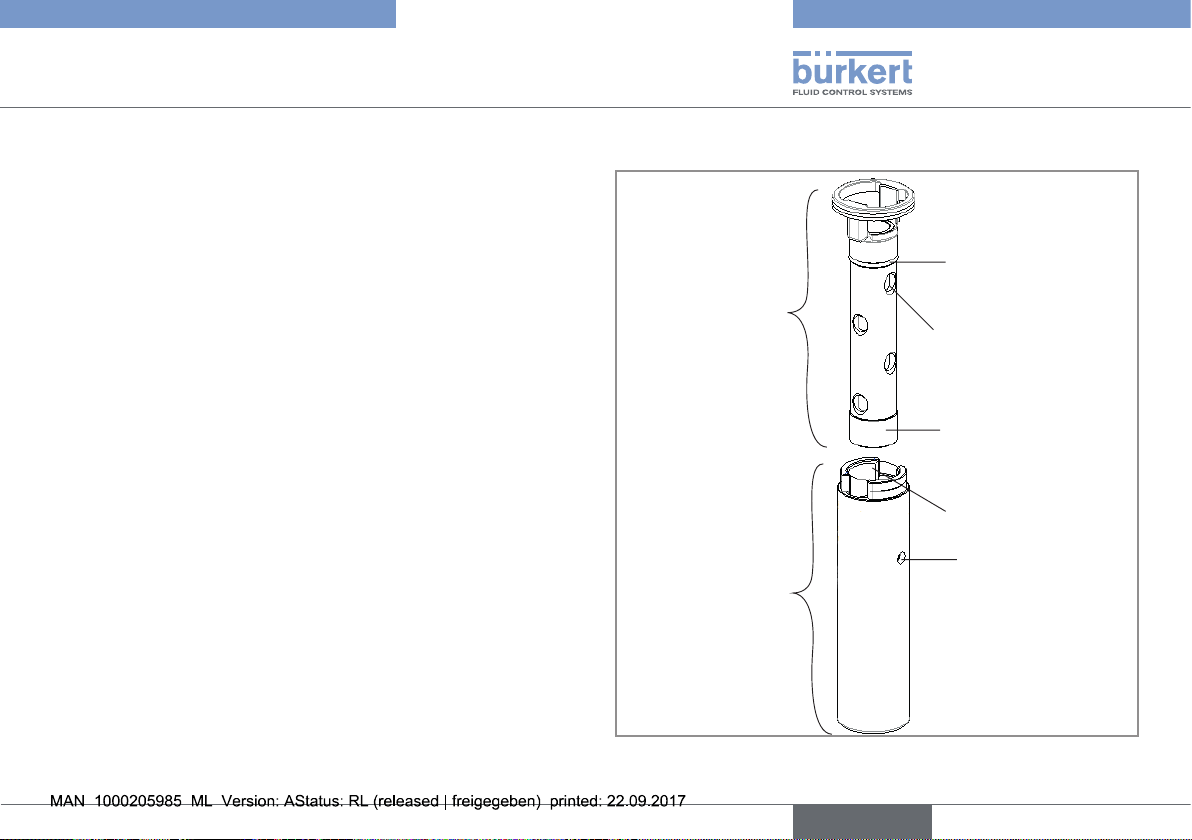
5.3. General description
Seal Pusher
Holes
Steel frame
O-ring
O-ring sleeve
(contains o-ring)
PG 13.5 thread
Pressure evacuation
holes (also accepts
cleaning adapter)
Fig. 1: Description of the holder
English
7
Type 8200
Technical data
6. TECHNICAL DATA
6.1. Conditions of use
Fluid temperature -30 to 140°C max.
Temperature limits may depend on the
inserted probe. Refer to the relevant
operating instructions. If the temperature
ranges given for the holder and the
inserted probe are different, use the most
restrictive range.
Pressure class 16 bar max.
Pressure limits may depend on the
inserted probe. Refer to the relevant operating instructions. If the pressure ranges
given for the holder and the inserted
probe are different, use the most restrictive range.
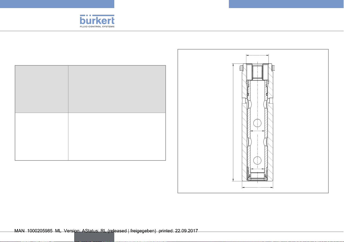
6.2. Dimensions
Pg 13.5
107
Ø 13
Ø 12,2
Ø12,2
Ø 28
Fig. 2: Dimensions [mm] of the direct welding holder
8
English
Type 8200
Installation, commissioning
6.3. Materials
Part Material
Steel frame Stainless steel
O-ring EPDM
Seal pusher Stainless Steel
7. INSTALLATION, COMMISSIONING
7.1. Safety instructions
danger
Risk of injury due to high pressure in the installation.
• Stop the circulation of fluid, cut-off the pressure and drain the
pipe before loosening the process connections.
Risk of injury due to high fluid temperatures.
• Use safety gloves to handle the holder.
• Stop the circulation of fluid and drain the pipe before loosening
the process connections.
Risk of injury due to the nature of the fluid.
• Respect the prevailing regulations on accident prevention and
safety relating to the use of hazardous products.
Warning
Risk of injury due to nonconforming installation.
• Fluidic installation can only be carried out by qualified and
authorised personnel with the appropriate tools.
• Observe the installation instructions for the measuring device
inserted into the fitting or the adapter.
Risk of injury due to an uncontrolled restart.
• Ensure that the restart of the installation is controlled after any
interventions on it.
English
9
Type 8200
Installation, commissioning
Warning
Danger due to nonconforming commissioning.
Nonconforming commissioning may lead to injuries and damage
the holder and its surroundings.
• Before commissioning, make sure that the staff in charge have
read and fully understood the contents of the manual.
• In particular, observe the safety recommendations and intended
use.
• The installation must only be commissioned by suitably trained
staff.
Warning
Gases or liquids can leak out indetected through the seals or
the screws.
• Check regularly the holder for leaks.
Warning
Before initial operation of the holder, or after a long out-of
use period:
• Ensure that the seal is tight.
• Ensure that all parts are in working order.
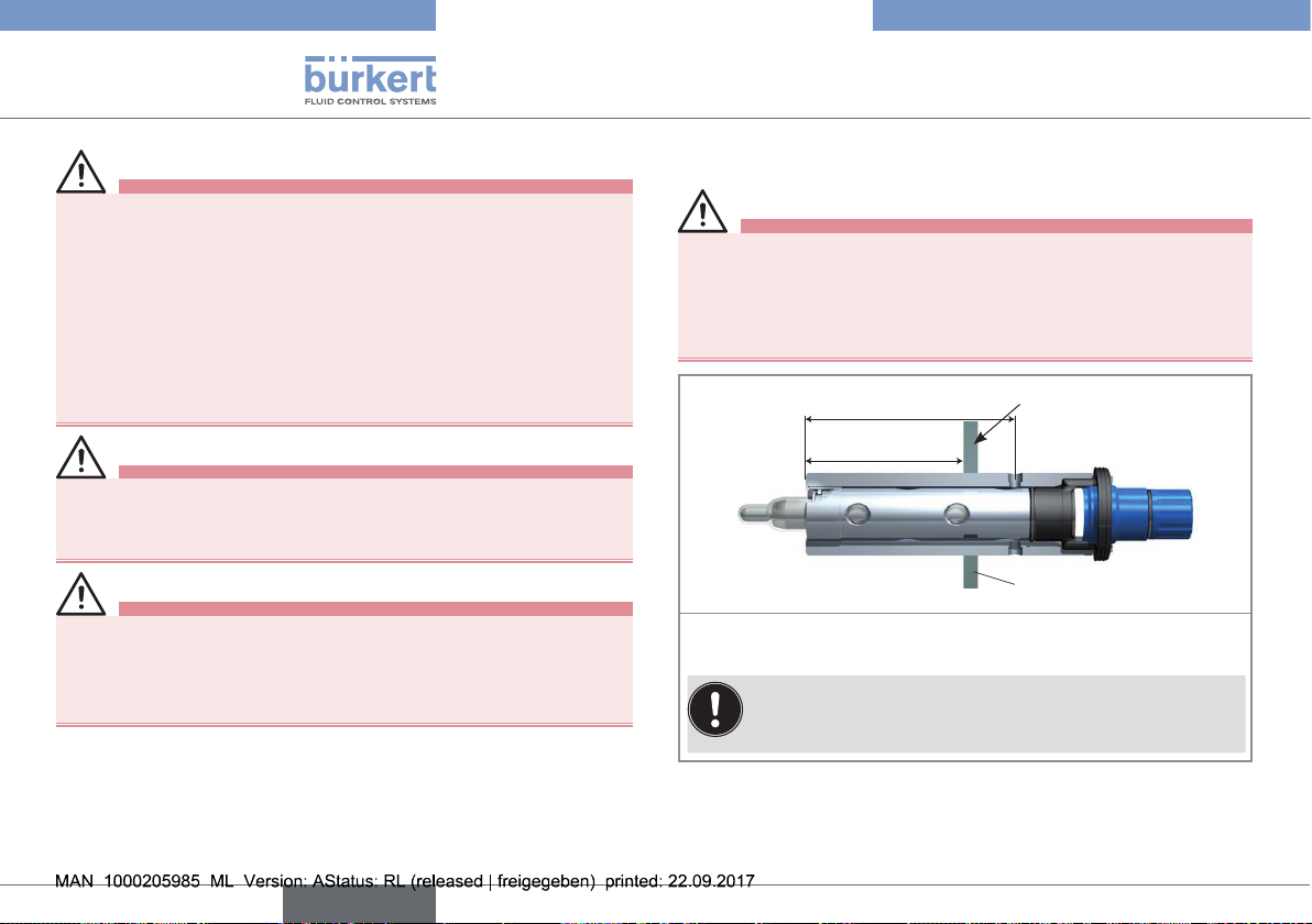
7.2. Installation onto the pipe
Warning
Risk of injury if the recommendations on installation of the
measuring device inserted into the holder are not observed
(see the relevant operating instructions).
• Take account of the recommendations on installation of the
inserted probe.
73 mm
0 to ~ 55 mm
Welding
Wall
→ Weld the steel frame into a circular cut-out of appropriate size
(28 mm diameter).
The holder can be welded at a depth of 0 to 55 mm.
Fig. 3: Dimensions [mm] for the installation of the holder onto the
pipe
10
English
Type 8200
Installation, commissioning
7.3. Inserting the probe
The holder is intended only for mounting probes with a
length of 120 mm.
Make sure the welded area has cooled down before
inserting the probe.
→ Ensure there is no damage to the probe or the holder.
→ Check that all o-rings are in place in their appropriate grooves,
and are free of damage.
→ Insert the seal pusher.
→ Screw the probe into the PG 13.5 thread at a locking torque
between 2 and 3 Nm.
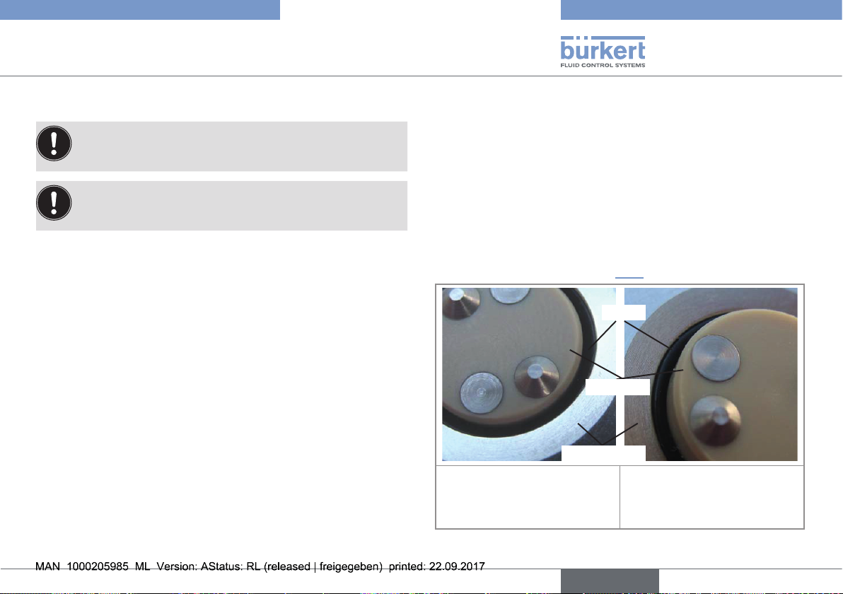
7.3.1. Operating mode
When a probe is screwed into the direct welding holder, the
seal pusher presses the o-ring into the space between the steel
frame and the probe shaft. This seals the probe in a manner that
almost completely eliminates crevices and their associated risk of
contamination.
When the probe is loosened, the o-ring relaxes again. This lowers
the friction between the o-ring and the other parts of the assembly,
and the process is no longer sealed.
If this takes place while the process is still under pressure, the pressure
evacuation holes feature (see chap. 7.3.2), automatically comes into use.
O-ring
Sensor tip
Steel mantle
Tip of a direct welding holder
with loose probe: the o-ring is
not under pressure.
Fig. 4: Tip of a direct welding holder with loose or tightened probe
Tip of a direct welding holder
with tightened probe: the o-ring,
under pressure, creates a seal
with no crevices.
English
11
Type 8200
Maintenance and troubleshooting
7.3.2. The pressure evacuation holes
feature
The direct welding holder is equipped with a safety mechanism, to
prevent danger to service personnel.
If the probe is unscrewed while there is still pressure in the process,
the o-ring between the probe and the steel frame of the holder loses
its seal. In this case, process medium enters the holder and exits
through the pressure evacuation holes before the probe is loosened
entirely (thereby informing the personnel that there is still pressure in
the process).
In this case, tighten again the probe until the process is no longer
under pressure. The probe can be then safely removed.
8. MAINTENANCE AND
TROUBLESHOOTING
8.1. Safety instructions
danger
Risk of injury due to high pressure in the installation.
• Stop the circulation of fluid, cut-off the pressure and drain the
pipe before loosening the process connections.
Risk of injury due to high fluid temperatures.
• Use safety gloves to handle the holder.
• Stop the circulation of fluid and drain the pipe before loosening
the process connections.
• Keep all easily flammable fluid or material away from the holder.
Risk of injury due to the nature of the fluid.
• Respect the prevailing regulations on accident prevention and
safety relating to the use of aggressive fluids.
Warning
Risk of injury due to nonconforming maintenance.
• Maintenance must only be carried out by qualified and skilled
staff with the appropriate tools.
• Ensure that the restart of the installation is controlled after any
interventions.
12
English
Type 8200
Maintenance and troubleshooting
8.2. Maintenance
Warning
After repairs or maintenance.
• Ensure that the seal is tight.
• Ensure that all parts are in working order.
note
Special attention must be given in the maintenance plan to the
o-rings. The o-rings used in direct welding holder are consumable
parts, and their life expectancy depends on the conditions in
which they operate. If the temperature frequently exceeds 100°C,
the o-rings must be replaced each time the probe is unscrewed,
because they are easily deformed under conditions of high temperature. If replacement of o-rings according to the plan is not
followed, leakage can occur.
→ Check and replace o-rings as required; always replace at least
once a year.
→ Check that the probe is tightly screwed into the holder. (Weekly
check recommended.)
→ Perform CIP cleaning as required by the type of process.
→ Clean the holder by means of the holes, if contamination with
medium.
→ Thoroughly clean the interior of the holder and the seal pusher if
the probe breaks.
8.3. Cleaning
note
The holder may be damaged by the cleaning product.
• Clean the holder with a cloth dampened with water or a detergent compatible with the materials the cleaning is made of.
• Never use scouring agent containing hard particles.
8.3.1. Cleaning in place (CIP)
If the installation into which the probe is built is being cleaned, the
parts of the holder and the probe that are normally in contact with
the medium (now in contact with the cleaning liquid) can be cleaned
in place, together with the rest of the installation.
8.3.2. Cleaning the interior of the direct
welding holder
If the space between probe and steel frame in the interior of the
holder becomes contaminated, it can be cleaned easily by fitting
cleaning adapters (not supplied by Bürkert) to the (non-threaded)
holes in the wall of the steel frame, and injecting a suitable cleaning
fluid. Alternatively, you can steam-sterilize.
English
13
Type 8200
Maintenance and troubleshooting
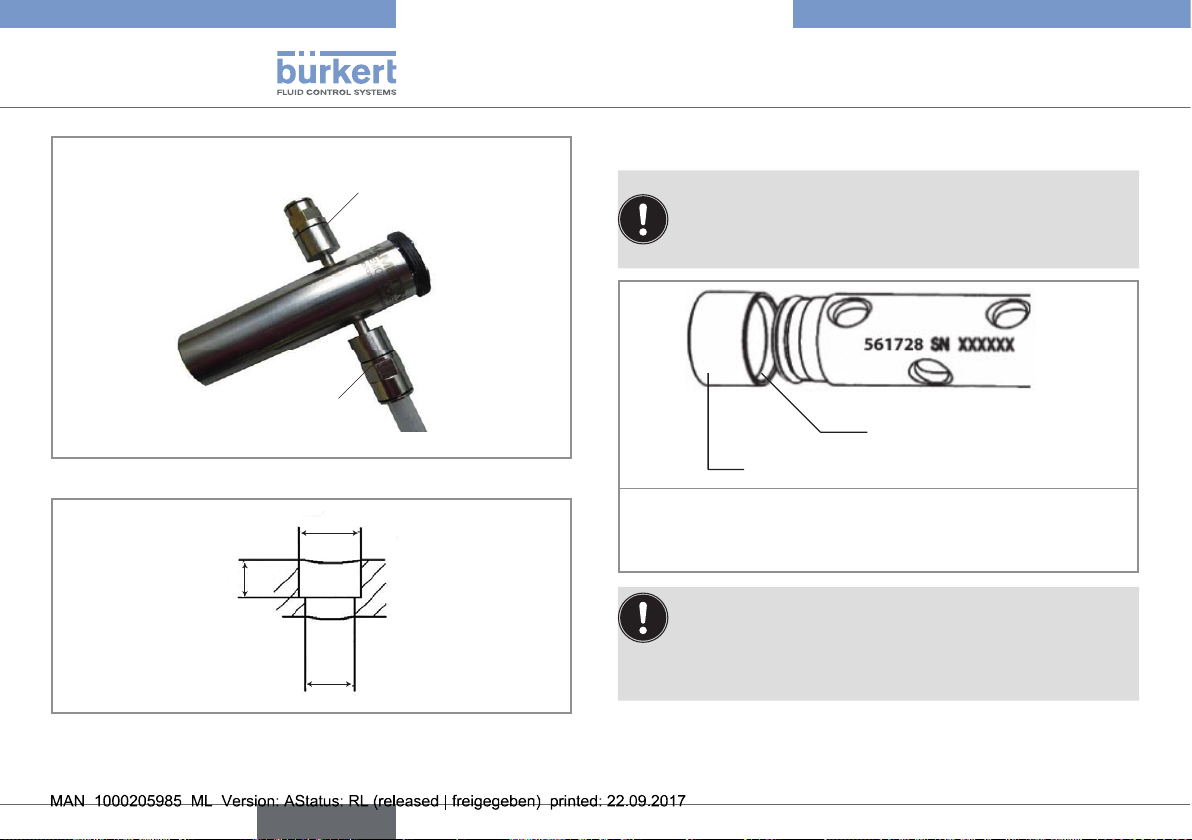
Cleaning adapter,
for example inlet
Cleaning adapter,
for example outlet
Fig. 5: Cleaning of the holder with cleaning adapters
Ø 5
3
Ø 4
8.3.3. Care of o-rings
• Check the o-rings from time to time.
• When mounting a new o-ring, take care not to damage
the o-ring nut and the o-ring. Otherwise the tightness can
no longer be guaranteed.
O-ring (inside the sleeve)
Sleeve
To replace the front o-ring:
→ Forcefully pull the sleeve from the seal pusher
→ Replace the o-ring
In higher temperature cycles (100 to 140°C) replace the
o-ring each time the probe is unscrewed. This is because
the compression set of EPDM must be considered (DIN
ISO 815, the deviation of the original o-ring form over time,
due to high temperature and pressure).
Fig. 6: Dimensions [mm] of a hole for cleaning adapters
14
English
Type 8200
Spare parts and accessories
9. SPARE PARTS AND
ACCESSORIES
attention
Risk of injury and/or damage caused by the use of unsuitable
parts.
Incorrect accessories and unsuitable spare parts may cause
injuries and damage the holder and the surrounding area.
• Use only original accessories and original spare parts from
Bürkert.
• By default, the direct welding holder is delivered with EPDM
o-rings.
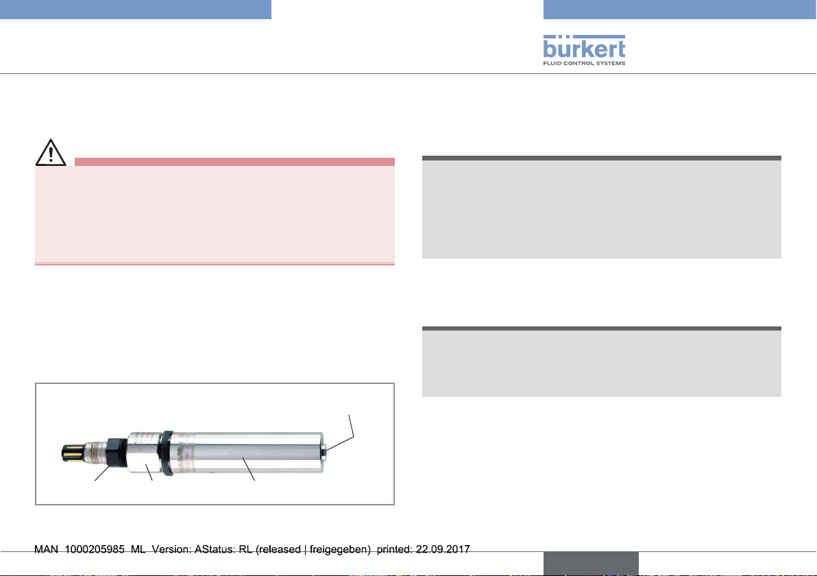
• The adapter with order code 563477 is useful for mounting 120
mm oxygen or conductivity probes. The adapter is screwed onto
the holder and the probe into the adapter. When in place, the end
of the probe is almost flush with the top of the holder.
End of the probe and of the direct
welding holder almost flush
Sensor head
Adapter
Direct welding holder
10. PACKAGING AND TRANSPORT
note
Damage due to transport
Transport may damage an insufficiently protected part.
• Transport the holder in shock-resistant packaging and away
from humidity and dirt.
• Do not expose the holder to temperatures that may exceed the
admissible storage temperature range.
11. STORAGE
note
Poor storage can damage the holder.
• Protect the direct welding holder from cold, wet, direct heat
sources (sun, heaters), soiling, and mechanical disturbance.
• Storage temperature : -30 to 140°C.
Fig. 7: Direct welding holder with adapter
English
15
 Loading...