


BUNN® ULTRA-2
INSTALLATION & OPERATING MANUAL
BUNN-O-MATIC CORPORATION
POST OFFICE BOX 3227
SPRINGFIELD, ILLINOIS 62708-3227
PHONE: (217) 529-6601 FAX: (217) 529-6644
32080.0000 03/03 © 2002 Bunn-O-Matic Corporation |
www.bunnomatic.com |
INTRODUCTION
This equipment dispenses granita-type and cold liquid drinks on demand from separate hoppers. Operating controls are accessible only through password protection.
CONTENTS
Introduction & Warranty ............................................................................................... |
2 |
User Notices .................................................................................................................. |
3 |
Site Preparation, Electrical Requirements ..................................................................... |
3 |
Initial Setup ................................................................................................................... |
4 |
Operating Controls ........................................................................................................ |
6 |
Programming ................................................................................................................ |
7 |
Using the Dispenser for Granita-Type Products .......................................................... |
18 |
Using the Dispenser for Cold Liquid Products ............................................................ |
18 |
Other Recommendations For Your Dispenser ............................................................. |
10 |
Recommended Daily Cleaning ..................................................................................... |
20 |
Schematic Wiring Diagrams ........................................................................................ |
22 |
BUNN-O-MATIC COMMERCIAL PRODUCT WARRANTY
Bunn-O-Matic Corp. (“BUNN”) warrants equipment manufactured by it as follows:
1)All equipment other than as specified below: 2 years parts and 1 year labor.
2)Electronic circuit and/or control boards: parts and labor for 3 years.
3)Compressors on refrigeration equipment: 5 years parts and 1 year labor.
4)Grinding burrs on coffee grinding equipment to grind coffee to meet original factory screen sieve analysis: parts and labor for 3 years or 30,000 pounds of coffee, whichever comes first.
These warranty periods run from the date of installation BUNN warrants that the equipment manufactured by it will be commercially free of defects in material and workmanship existing at the time of manufacture and appearing within the applicable warranty period. This warranty does not apply to any equipment, component or part that was not manufactured by BUNN or that, in BUNN’s judgment, has been affected by misuse, neglect, alteration, improper installation or operation, improper maintenance or repair, damage or casualty. This warranty is conditioned on the Buyer 1) giving BUNN prompt notice of any claim to be made under this warranty by telephone at (217) 529-6601 or by writing to Post Office Box 3227, Springfield, Illinois 62708-3227; 2) if requested by BUNN, shipping the defective equipment prepaid to an authorized BUNN service location; and 3) receiving prior authorization from BUNN that the defective equipment is under warranty.
THE FOREGOING WARRANTY IS EXCLUSIVE AND IS IN LIEU OF ANY OTHER WARRANTY, WRITTEN OR ORAL, EXPRESS OR IMPLIED, INCLUDING, BUT NOT LIMITED TO, ANY IMPLIED WARRANTY OF EITHER MERCHANTABILITY OR FITNESS FOR A PARTICULAR PURPOSE. The agents, dealers or employees of BUNN are not authorized to make modifications to this warranty or to make additional warranties that are binding on BUNN. Accordingly, statements by such individuals, whether oral or written, do not constitute warranties and should not be relied upon.
If BUNN determines in its sole discretion that the equipment does not conform to the warranty, BUNN, at its exclusive option while the equipment is under warranty, shall either 1) provide at no charge replacement parts and/ or labor (during the applicable parts and labor warranty periods specified above) to repair the defective components, provided that this repair is done by a BUNN Authorized Service Representative; or 2) shall replace the equipment or refund the purchase price for the equipment.
THE BUYER’S REMEDY AGAINST BUNN FOR THE BREACH OF ANY OBLIGATION ARISING OUT OF THE SALE OF THIS EQUIPMENT, WHETHER DERIVED FROM WARRANTY OR OTHERWISE, SHALL BE LIMITED, AT BUNN’S SOLE OPTION AS SPECIFIED HEREIN, TO REPAIR, REPLACEMENT OR REFUND.
In no event shall BUNN be liable for any other damage or loss, including, but not limited to, lost profits, lost sales, loss of use of equipment, claims of Buyer’s customers, cost of capital, cost of down time, cost of substitute equipment, facilities or services, or any other special, incidental or consequential damages.
2 |
32080 031103 |
|
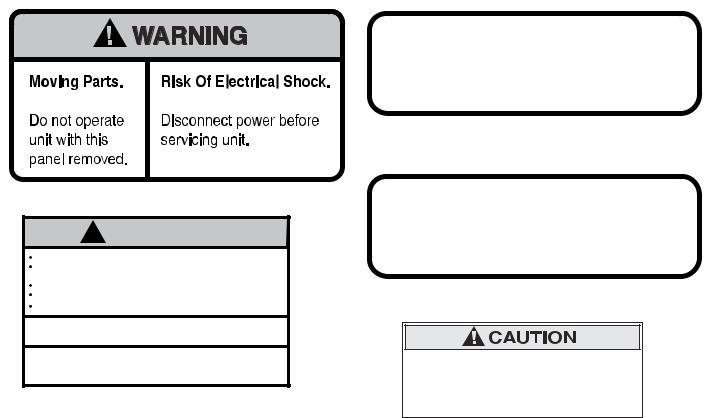
USER NOTICES
Carefully read and follow all notices on the equipment and in this manual. They were written for your protection. All notices are to be kept in good condition. Replace any unreadable or damaged labels.
27442.0000
! WARNING
DO NOT OVERLOAD CIRCUIT.
ALWAYS ELECTRICALLY GROUND THE CHASSIS OR ADAPTOR PLUG.
DO NOT DEFORM PLUG OR CORD.
FOLLOW NATIONAL AND LOCAL ELECTRICAL CODES. KEEP COMBUSTIBLES AWAY.
FAILURE TO COMPLY RISKS EQUIPMENT DAMAGE, FIRE OR SHOCK HAZARD.
READ THE ENTIRE OPERATING MANUAL
BEFORE USING THIS PRODUCT
00986.0002E 5/98 ©1994 Bunn-O-Matic Corporation
00986.0002
CHARGE
Type R404A, Amount 10 oz Design Pressures: High 240 Low 34
32162.0000 (ULTRA-2)
CHARGE
Type R404A, Amount 9.5 oz(269g)
Design Pressures: High 215 Low 40
29373.0000 (ULTRA-2A)
Risk of Electric Shock.
This equipment may have two power supply cords. Unplug all cords before moving or servicing this equipment.
29947.0000
SITE PREPARATION
The dispenser is very heavy. Place it on a sturdy counter or shelf capable of supporting at least 180 lbs. It is for indoor use only.
The dispenser must have at least six inches of space behind it. This space is needed for airflow, air filter removal, and cleaning. A clearance of at approximately six inches is recommended between the dispenser sides and the wall or another appliance. The dispenser performs better if not placed near any heating appliance. Leave some space so the dispenser can be moved for cleaning.
ELECTRICAL REQUIREMENTS
CAUTION – Improper electrical installation will damage components. An electrician must provide electrical service as specified below.
Model ULTRA-2, This dispenser has an attached cordset and requires a 2-wire, grounded, individual branch circuit rated 120 volts ac, 15 amp, single phase, 60 Hz. The mating connector must be a NEMA 5-15R.
(Refer to the dataplate for exact electrical requirements.)
Model ULTRA-2A, This dispenser has an attached cordset and requires a 2-wire, grounded, individual branch circuit rated 230 volts ac, 10 amp, single phase, 50 Hz. (Refer to the dataplate for exact electrical requirements.)
NOTE – Bunn-O-Matic does not recommend the use of any extension cord with these dispensers.
3 |
32080 040802 |
|
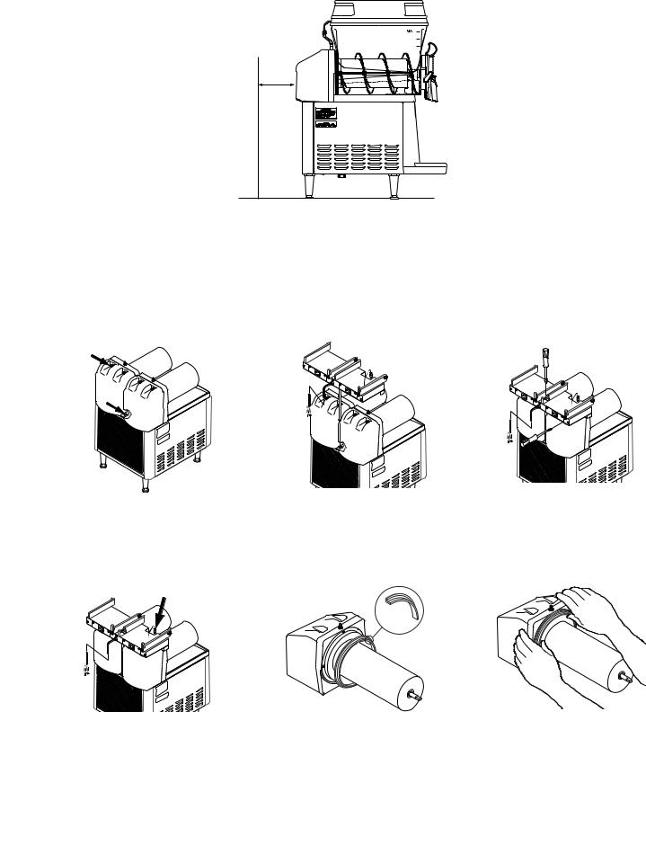
INITIAL SETUP
CAUTION – The dispenser is very heavy! Use care when lifting or moving it. Use at least two people to lift or move the dispenser.
6.0" |
MIN. |
1.Set the dispenser on a sturdy counter top. The dispenser requires a minimum of 6.0" air clearance at the rear of the dispenser. For optimum performance, do not let warm air from surrounding machines blow on the
ULTRA -2.
NOTE – The dispenser should be level or slightly lower in front for proper operation.
2.Remove all shipping material, including the compressor support eyebolt, the cooling drum supports, the “Do Not Lift Here” signs from the cooling drums, and the “Rinse Before Using” signs from each hopper. For models without PAF (Powder Auto-Fill™), proceed to step #7.
3. Remove the rear plastic plug 4. |
Place PAF platform assembly 5. |
Tighten support rod from top |
from the trim strip between the |
on top of the motor covers and |
of platform. Retighten motor |
hopper drip trays and loosen |
install support rod into hole in |
cover screws. |
the auger motor cover screws. |
trim strip. |
|
6. Plug RCA cord into ULTRA base 7. |
Install each hopper seal over 8. |
Press the seals firmly into |
unit. Proceed with steps 7 thru |
the flange at the rear of the |
place. |
12. |
cooling drums as shown. |
|
4 |
32080 021202 |
|

INITIAL SETUP (CONT.)
9.Align the auger shaft with the flat fin of the auger. Push the augers as far as they will go and rotate them so the flat fin is facing up.
12.Slide them into place and push them down until the hopper lock plungers snap into place. For models without PAF, proceed to step 15.
15.Set the lids on the hoppers. Lift slightly and slide back or front for filling.
10.Install auger nose bushing into inside front of hopper.
13.For models with PAF, install level probes into slots at top rear of PAF hoppers.
16.Plug in the hopper lid lamp cords.
11.Thoroughly rinse the hoppers and install them over the augers and cooling drums.
14.Install PAF unit onto platform and plug power cord into rear of platform. Plug platform power cord into proper outlet. (Refer to PAF manual for water connections)(Proceed to step 17)
17. Assemble the drip tray.
5 |
32080 021202 |
|
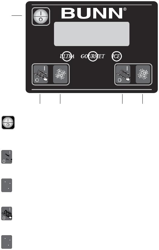
OPERATING CONTROLS
There are five of these switches that will be used for the operation of the dispenser.
1
2 |
3 |
4 |
5 |
1. switch (upper left corner of the control pad)
This switch is the ON/OFF toggle switch which powers up the dispenser and the LCD display. When ON the Date and Time toggle back and forth continously except during programming.
2. 
 (bottom left corner)
This is used to turn the left side auger motor ON or OFF.
3.  (bottom left corner)
This is used to turn the left side ice control to OFF, ICE or CHILL.
4. 
 (bottom right corner)
This is used to turn the right side auger motor ON or OFF.
5.  (bottom right corner)
This is used to turn the right side ice control to OFF, ICE or CHILL.
6 |
32080 021202 |
|
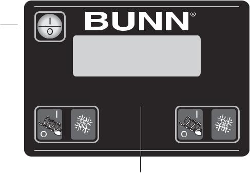
PROGRAMMING
Using the menu-driven display on the front of the dispenser, the operator has the ability to alter or modify various parameters such as beverage consistency and set day/night “ON/OFF” times. The operator is also prompted to check a variety of periodic service functions or even a step-by-step cleaning routine. There is also the opportunity to return all changes back to factory default settings.
Access to most controls can be password protected to allow only qualified personnel to make changes.
1
2 


 4
4
3
PROGRAMMING SWITCHES
To access the programming mode, and to scroll through the different function screens, hidden programming switches are used. There are three of these switches that will be used for the setup of the dispenser.
1. I/O switch (upper left corner of the control pad)
This switch is the ON/OFF toggle switch which powers up the dispenser and the LCD display. This switch is also used as back up switch in menu mode.
2. “GOURMET” (center under display)
Press and hold this switch 5 seconds to access the Menu Function Index. This switch is also used as “NEXT” to scroll through the functions.
3. “ULTRA” (left under display)
When prompted by a selection from the menu to answer yes or no, the “ULTRA” switch is used to answer “NO” or (-) minus.
4. “ICE” (right under display)
When prompted by a selection from the menu to answer yes or no, the “ICE” switch is used to answer “YES” or (+) plus.
7 |
32080 021202 |
|
 Loading...