


CRESCENDO
INSTALLATION & OPERATING GUIDE
BUNN-O-MATIC CORPORATION
POST OFFICE BOX 3227
SPRINGFIELD, ILLINOIS 62708-3227
PHONE: (217) 529-6601 FAX: (217) 529-6644
To ensure you have the latest revision of the Operating Manual, or to view the Illustrated Parts Catalog, Programming Manual, or Service Manual, please visit the Bunn-O-Matic website, at www.bunn.com. This is absolutely FREE, and the quickest way to obtain the latest catalog and
manual updates. For Technical Service, contact Bunn-O-Matic Corporation at 1-800-286-6070.
52384.0001B 09/17 ©2016 Bunn-O-Matic Corporation
BUNN-O-MATIC COMMERCIAL PRODUCT WARRANTY
Bunn-O-Matic Corp. (“BUNN”) warrants the BUNN Crescendo as further described below for a warranty period of 1 year parts and labor.
These warranty periods run from the date of installation. BUNN warrants that the equipment manufactured by it will be commercially free of defects in material and workmanship existing at the time of manufacture and appearing within the applicable warranty period. This warranty does not apply to any equipment, component or part that was not manufactured by BUNN or that, in BUNN’s judgment, has been affected by misuse, neglect, alteration, improper installation or operation, improper maintenance or repair, non periodic cleaning and descaling, equipment failures related to poor water quality, damage or casualty. This warranty is conditioned on the Buyer 1) giving BUNN prompt notice of any claim to be made under this warranty by telephone at (217) 529-6601 or by writing to Post Office Box 3227, Springfield, Illinois 62708-3227; 2) if requested by BUNN,
shipping the defective equipment prepaid to an authorized BUNN service location; and 3) receiving prior authorization from BUNN that the defective equipment is under warranty. Additionally, the following is excluded from the warranty period: Warranty Exclusions:
•Parts such as, but not limited to, hoppers and lids, drip trays, and plastic parts damaged due to improper handling or cleaning agents.
•Replacement of wear items such as, but not limited to, O-rings, gaskets, silicone tubes, hoses, and valve seats.
•Repairs made necessary due to poor water quality such as dispense valves, water inlet valves, scaling in the steam or hot water boilers. (Total Hardness recommended range of 4-7 gpg constant).
•Improper voltage. (See equipment operations manual for voltage specifications).
•Failure to use BUNN approved cleaning supplies constitutes improper maintenance.
•Failure to have required preventive maintenance performed by BUNN technician or authorized espresso service provider.
•Parts replaced under the terms of this warranty carry the remainder on the machine’s parts warranty term, or 60 days,
whichever is greater.
THE FOREGOING WARRANTY IS EXCLUSIVE AND IS IN LIEU OF ANY OTHER WARRANTY, WRITTEN OR ORAL, EXPRESS OR IMPLIED, INCLUDING, BUT NOT LIMITED TO, ANY IMPLIED WARRANTY OF EITHER MERCHANTABILITY OR FITNESS FOR A PARTICULAR PURPOSE. The agents, dealers or employees of BUNN are not authorized to make modifications to this warranty or to make additional warranties that are binding on BUNN. Accordingly, statements by such individuals, whether oral or written, do not constitute warranties and should not be relied upon. If BUNN determines in its sole discretion that the equipment does not conform to the warranty, BUNN, at its exclusive option while the equipment is under warranty, shall either 1) provide at no charge replacement parts and/or labor (during the applicable parts and labor warranty periods specified above) to repair the defective components, provided that this repair is done by a BUNN Authorized Service Representative; or 2) shall replace the equipment or refund the purchase price for the equipment.
THE BUYER’S REMEDY AGAINST BUNN FOR THE BREACH OF ANY OBLIGATION ARISING OUT OF THE SALE OF THIS EQUIPMENT, WHETHER DERIVED FROM WARRANTY OR OTHERWISE, SHALL BE LIMITED, AT BUNN’S SOLE OPTION AS SPECIFIED HEREIN, TO REPAIR, REPLACEMENT OR REFUND. In no event shall BUNN be
liable for any other damage or loss, including, but not limited to, lost profits, lost sales, loss of use of equipment, claims of Buyer’s customers, cost of capital, cost of down time, cost of substitute equipment, facilities or services, or any other special, incidental or consequential damages.
392, A Partner You Can Count On, Air Infusion, AutoPOD, AXIOM, BrewLOGIC, BrewMETER, Brew Better Not Bitter, BrewWISE, BrewWIZARD, BUNN Espress, BUNN Family Gourmet, BUNN Gourmet, BUNN Pour-O-Matic, BUNN, BUNN with the stylized red line, BUNNlink, Bunn-OMatic, Bunn-O-Matic, BUNNserve, BUNNSERVE with the stylized wrench design, Cool Froth, DBC, Dr. Brew stylized Dr. design, Dual, Easy Pour, EasyClear, EasyGard, FlavorGard, Gourmet Ice, Gourmet Juice, High Intensity, iMIX, Infusion Series, Intellisteam, My Café, Phase Brew, PowerLogic, Quality Beverage Equipment Worldwide, Respect Earth, Respect Earth with the stylized leaf and coffee cherry design, Safety-Fresh, vemycoffee.com, Scale-Pro, Silver Series, Single, Smart Funnel, Smart Hopper, SmartWAVE, Soft Heat, SplashGard, The Mark of Quality in Beverage Equipment Worldwide, ThermoFresh, Titan, trifecta, TRIFECTA (sylized logo), Velocity Brew, Air Brew, Beverage Bar Creator, Beverage Profi t Calculator, Brew better, not bitter., Build-A-Drink, BUNNSource, Coffee At Its Best, Cyclonic Heating System, Daypart, Digital Brewer Control, Element, Milk Texturing Fusion, Nothing Brews Like a BUNN, Picture Prompted Cleaning, Pouring Profi ts, Signature Series, Sure Tamp, Tea At Its Best, The Horizontal Red Line, Ultra are either trademarks or registered trademarks of Bunn-O-Matic Corporation. The commercial trifecta® brewer housing configuration is a trademark of Bunn-O-Matic Corporation.
2 |
52384.1 |
031314 |

USER NOTICES
The notices on this dispenser should be kept in good condition. Replace unreadable or damaged labels.
00656.0001
00986.0000
12368.0002 |
37881.0000 |
00824.0002
3 |
52384.1 |
062217 |
|
CE REQUIREMENTS
•This appliance must be installed in locations where it can be overseen by trained personnel.
•For proper operation, this appliance must be installed where the temperature is between 5°C to 35°C.
•Appliance shall not be tilted more than 10° for safe operation.
•An electrician must provide electrical service as specified in conformance with all local and national codes.
•This appliance must not be cleaned by water jet.
•This appliance can be used by persons aged from 18 years and above if they have been given supervision or instruction concerning use of the appliance in a safe way and if they understand the hazards involved.
•Keep the appliance and its cord out of reach of children aged less than 18 years.
•Appliances can be used by persons 18 years and above with reduced physical, sensory or mental capabilities or lack of experience and knowledge if they have been given supervision or instruction concerning use of the appliance in a safe way and understand the hazards involved.
•Children under the age of 18 years should be supervised to ensure they do not play with the appliance.
•If the power cord is ever damaged, it must be replaced by the manufacturer or authorized service personnel with a special cord available from the manufacturer or its authorized service personnel in order to avoid a hazard.
•Machine must not be immersed for cleaning.
•Cleaning and user maintenance shall not be made by children unless they are older than 18 years and supervised.
•This appliance is intended to be used in household and similar applications such as:
–staff kitchen areas in shops, offices and other working environments;
–by clients in hotels, motels and other residential type environments;
–bed and breakfast type environments.
•This appliance not intended to be used in applications such as:
–farm houses;
•Access to the service areas permitted by Authorized Service personnel only.
•The A-Weighted sound pressure level is below 70 dBA.
NORTH AMERICAN REQUIREMENTS
•This appliance must be installed in locations where it can be overseen by trained personnel.
•For proper operation, this appliance must be installed where the temperature is between 41°F to 95°F (5°C to 35°C).
•Appliance shall not be tilted more than 10° for safe operation.
•An electrician must provide electrical service as specified in conformance with all local and national codes.
•This appliance must not be cleaned by pressure washer.
•This appliance can be used by persons aged from 18 years and above if they have been given supervision or instruction concerning use of the appliance in a safe way and if they understand the hazards involved.
•Keep the appliance and its cord out of reach of children aged less than 18 years.
•Appliances can be used by persons 18 years and above with reduced physical, sensory or mental capabilities or lack of experience and knowledge if they have been given supervision or instruction concerning use of the appliance in a safe way and understand the hazards involved.
•Children under the age of 18 years should be supervised to ensure they do not play with the appliance.
•If the power cord is ever damaged, it must be replaced by the manufacturer or authorized service personnel with a special cord available from the manufacturer or its authorized service personnel in order to avoid a hazard.
•Machine must not be immersed for cleaning.
•Cleaning and user maintenance shall not be made by children unless they are older than 18 years and supervised.
•This appliance is intended for commercial use in applications such as:
–staff kitchen areas in shops, offices and other working environments;
–by clients in hotel and motel lobbies and other similar types of environments;
•Access to the service areas permitted by Authorized Service personnel only.
4 |
52384.1 |
062217 |
INITIAL SET-UP
1.Remove drip tray and cover from the parts box. Assemble the cover to the drip tray, then slide under the front door of the machine, engaging the rear of the drip tray into the opening in the lower front of the machine..
2.Remove the espresso brew group from the parts box.
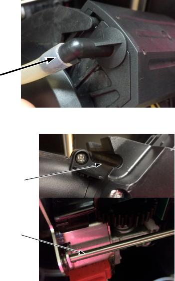
3.Slide tube onto elbow fitting on upper left side of espresso group head as shown in Figure 1.
Figure 1 |
P4375 |
4.Place groove on lower front of group head over mounting bar on espresso drive as shown in Figure 2.
Groove
Mounting
Bar
Figure 2 |
P4376 |
5 |
52384.1 |
062217 |
|
INITIAL SET-UP - continued
6.Rotate the top of group head toward rear of machine until it snaps into place as shown in Figure 3.
7.Slide red lock to the right until it snaps into place as shown in Figure 4.
8.Install group head tube into quick connect fitting on bottom of espresso drive, insuring that the tube is fully inserted as shown in Figure 5.
Brew Tube
Connection
Figure 3 |
P4377 |
Figure 4 |
P4378 |
Figure 5 |
P4379 |
6 |
52384.1 |
062217 |
INITIAL SET-UP - continued
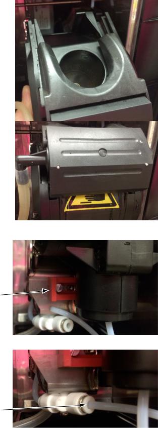
9.Remove the bean hopper from the parts box. Align the bean hopper so that the collar on the bottom of the bean hopper will engage the opening in the grinder as shown in Figure 6.
Figure 6
10.When the hopper is in place on the grinder, pull the hopper gate all the way forward to allow beans into the grinder, then lock hopper in place as shown in Figure 7.
CAPACITY
Figure 7
1.Brew chamber has a capacity rating of 5 gm minimum up to 15 gm maximum of espresso grind coffee.
2.Brewer has a peak capacity of 60 single (small) espresso shots per hour.
ELECTRICAL REQUIREMENTS
CAUTION - The dispenser must be disconnected from the power source until specified in Electrical Hook-Up.
Electrical Hook-Up
CAUTION - Improper electrical installation will damage electronic components.
1.An electrician must provide electrical service as specified.
2.Using a voltmeter, check the voltage and color coding of each conductor at the electrical source.
3.Connect the dispenser to the power source.
4.If plumbing is to be hooked up later be sure the dispenser is disconnected from the power source. If plumbing has been hooked up, the dispenser is ready for Initial Fill & Heat.
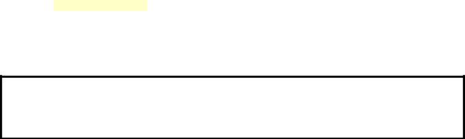
120V
Models
120 & 220-240 volt ac models
Note: This electrical service consists of 2 current carrying conductors (L1 and Neutral) and a separate conductor for chassis ground.
220-240 VOLT Models
7 |
52384.1 |
062217 |
|
PLUMBING REQUIREMENTS
This dispenser must be connected to a cold water system with operating pressure between 138 - .620 MPa (20 and 90 psi) from a 1⁄2” or larger supply line. A shut-off valve should be installed in the line before the dispenser. Install a regulator in the line when pressure is greater than .620 MPa (90 psi) to reduce it to .345 MPa (50 psi). The water inlet fitting is 3/4 British Parallel Pipe.
NOTE - Bunn-O-Matic recommends 6mm copper tubing for installations of less than 25 feet and 8mm for more than 25 feet from the water supply line. At least 18 inches of an FDA approved flexible beverage tubing, such as reinforced braided polyethylene or silicone, before the dispenser will facilitate movement to clean the counter top. Bunn-O-Matic does not recommend the use of a saddle valve to install the dispenser. The size and shape of the hole made in the supply line by this type of device may restrict water flow.
As directed in the International Plumbing Code of the International Code Council and the Food Code Manual of the Food and Drug Administration (FDA), this equipment must be installed with adequate backflow prevention to comply with federal, state and local codes. For models installed outside the U.S.A., you must comply with the applicable Plumbing /Sanitation Code for your area.
NOTE - If a backflow preventer is required by code, a shock arrestor should be installed between backflow preventer and dispenser. Installing the shock arrestor as close to the dispenser as possible will provide the best results.
NOTE - Water pipe connections and fixtures directly connected to a potable water supply shall be sized, installed and maintained in accordance with federal, state and local codes.
PLUMBING HOOK-UP
NOTE: The plumbing connection is located on the back of the unit, using the water line included with some models, that connects to a 3/8” male flare.
1.Flush the water line and securely attach it to the valve threads on the rear of the dispenser.
2.Turn on the water supply.
INITIAL FILL & HEAT
1.Turn on the water supply, connect power to the dispenser, and place the main power switch on the rear of the machine to the ON position.
2.Water will automatically flow into the soluble tank to the proper level, then shut off. This will take less than five minutes.
3.The screen on the front door will display FILL ESPRSO TANK. Press the button under START.
4.The screen will display MOVING BREW CHAMBER, ESP TANK FILLING, and the espresso tank will begin filling. This may take several minutes.
5.When water dispenses from the espresso nozzle into the drip tray, press YES under WATER DISPENSED? to stop the tank filling.
6.The tanks will then begin heating. When the tanks have completed heating, the display will read “READY TO BREW SELECT SIZE”.
PRESET TANK TEMPERATURE
The tank temperatures have been preset at the factory to 80°C (180°F) for the soluble tank, and 102°C (215°F) for the espresso tank. Bunn recommends that to provide the best quality beverage, the installer adjust the tank temperature to the powder product manufacturers recommended temperature for the hot powder product being used.
7.Fill the hopper(s) with the dry product to be dispensed.
8.Fill the bean hopper with the whole beans to be ground and brewed.
LIQUID LEVEL CONTROL
The system automatically maintains the soluble hot water tank’s level by energizing the refill solenoid when the water level drops below the liquid level probe. If the system has not successfully refilled, a refill error occurs. When a refill error occurs, the refill solenoid is de-energized. Once the cause of the refill error has been investigated and cured, the system can be reset by either cycling the power to the machine (at least five seconds) using the main power switch at the rear of the machine, or by entering one of the program modes (see Programming Modes.)
8 |
52384.1 |
062217 |

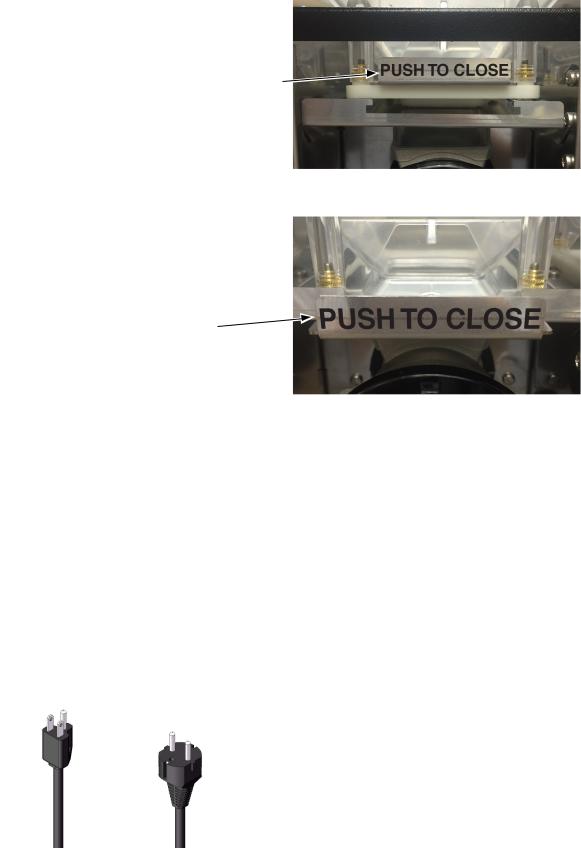
Filling Soluble Hoppers
1.Remove packing material from on top of the powder hoppers.
2.Remove powder hoppers by lifting the front of the powder
hopper until the peg on the bottom of the hopper clears the hole in the mounting plate (see Figure 1). Then pull the hopper forward to remove.
Figure 1
3.Set the hoppers on the counter, and push the slide gates on the front of the discharge chutes inward (see Figure 2) to close the gates.
Figure 2
4.Remove hopper lids and fill the hoppers with appropriate soluble products. Default menu is milk product left hopper, chocolate is center hopper, and vanilla is right hopper. Replace hopper lids.
5.Reinstall hoppers back into machine, make sure peg on bottom of hopper drops into locating hole on hopper platform.
6.After hoppers are installed, discharge chutes must be rotated as shown in Figure 3.
Figure 3
9 |
52384.1 |
062217 |
|
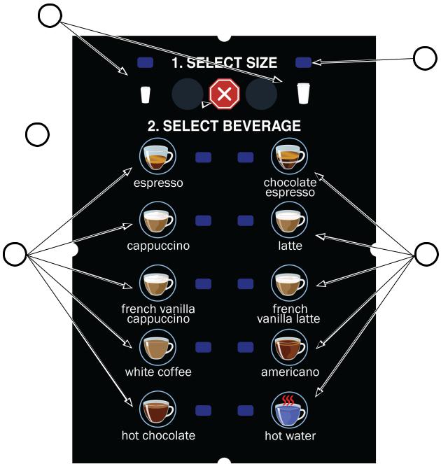
OPERATING CONTROLS AND INTERFACE
1.Cup Size Buttons: Momentarily pushed to select beverage size to dispense.
2.Dispense Buttons: Momentarily pushed to dispense selected beverage
3.LED indicators: Illuminates when the adjoining button has been selected.
4.Stop button: Pressing the stop button during dispensing will stop the dispense sequence.
1
3
4 
2 |
2 |
OPERATING THE DISPENSER
The NORMAL/PROGRAM/RINSE switch must be in the NORMAL position
1.Place a cup on the drip tray beneath the dispense nozzle.
2.In the area marked “1” of the control panel:
a.Select desired beverage size, small or large cup. This selection is mandatory for dispensing.
3.In the area marked “2” of the control panel:
a.Press the button to dispense the desired beverage. Dispensing is portion controlled, and will automatically stop when the correct amount of beverage has been dispensed.
10 |
52384.1 |
062217 |
MODIFYING THE TOUCH SWITCH FUNCTIONS
The function of the touch switch can be modified in four different ways:
1.Set for single cup size dispensing.
2.Move any default beverage from one switch location to another.
3.Disable a dispense switch.
4.Create a “custom” beverage in any switch location.
SINGLE CUP SIZE DISPENSING
In this mode, a selection can be made to dispense one cup size beverage only. When the SINGLE cup size beverage mode is selected, the large and small cup size buttons are disabled. To dispense a beverage, press only the dispense button of the beverage desired. It is recommended that the touch switch graphic insert be replaced with a new graphic that does not show the large and small cup button in this mode. Reference PROGRAMMING SWITCHES diagram on page 30, and on the flow chart on page 33.
1.In the PROGRAM mode, use the LARGE cup size button, top far right, to navigatge to the “RECIPE SET UP?” screen.
2.Press the button under “YES” (button “B”), and “USER SELECT MODE” screen will appear.
3.To change from a “MULTI”, small and large cup sizes, to a “SINGLE” cup size, press the button under “SINGLE”, (button “D”), and “SINGLE” will flash to verify the selection.
4. |
Press |
to accept the selection and exit to the “PROGRAM MODE” screen. |
5. |
When complete, return to the NORMAL\PROGRAM\RINSE switch to the NORMAL position. |
|
CHANGING DEFAULT BEVERAGE SWITCH LOCATION or DISABLING A DISPENSE SWITCH
Any default beverage can be moved to a different switch location, or any dispense switch can be disabled. It is recommended that the touch switch graphic insert be replaced with one that matches the beverage reassignments made in this mode. Reference PROGRAMMING SWITCHES diagram on page 30, and on the flow chart on page 34.
1.In the PROGRAM mode, use the LARGE cup size button, top far right, to navigate to the “RECIPE SETUP?” screen.
2.Press the button under “YES” (button “B”) and then the LARGE cup size button untill the screen displays the “SETUP SW ## RECIPE” for the desired switch to be modified.
3.In the “SETUP SW ## RECIPE” screen, press the button under “YES” (button “B”) to modify that switch setup.
4.Press the button under (+), (button “B”) to scoll through the recipe names until the desired beverage is displayed. If “DISABLE” is selected as a recipe, this dispense switch will be disabled.
5.After the desired recipe name is displayed, press the LARGE cup size button to advance to the “SW # SMALL TM” screen. The amount of soluble product in the beverage can be adjusted by using the (-) (button “D”) or the (+) (button “B”) button to change the dispense time.
6.Press the LARGE cup size button to advance to the “SW # LARGE TM” screen. The amount of soluble product in the beverage can be adjusted byusing the (-) (“D”) or the (+) (“B”) button to change the dis-
pense time. Press  to exit this menu.
7. Return the NORMAL\PROGRAM\RINSE switch to the NORMAL position.
11 |
52384.1 |
062217 |
|
MODIFYING THE TOUCH SWITCH FUNCTIONS - CONTINUED
CREATING A “CUSTOM” BEVERAGE
In this mode, a “CUSTOM” beverage may be created in any dispense switch location. A CUSTOM beverage consists of product from one or two soluble hoppers, and may include a shot of espresso. Or, instead of a soluble component,
“DILUTION” may be selected to pair with an espresso shot to create an AMERICANO type beverage. It is recommended that the touch switch graphic insert be replaced with one which matches the beverage reassignments made in this mode. Reference PROGRAMMING SWITCHES diagram on page 30, and on the flow chart on page 35.
1.In the PROGRAM mode, use the LARGE cup size button, top far right, to navigate to the “RECIPE SETUP?” screen.
2.Press the button under “YES” (button “B”) and “USER SELECT MODE” screen will appear.
3.Press the LARGE cup size button until the screen displays the “SETUP SW ## RECIPE” for the desired switch to be modified.
4.Press the button under (+), (button “B”) to scoll through the recipe names until “CUSTOM” is displayed.
5.Press the LARGE cup button to advance to the “SW # SMALL TM” screen. The amount of soluble dilution water in the beverage can be adjusted by using the (-) (“D”) or the (+) (“B”) button to change the dispense time. Note: This is the total soluble dilution water dispense time for either a single soluble component or both soluble components. It is also the dispense time if DILUTION is selected. The nominal flow rate is 22ml per second, (.74 oz/sec). So the dispense time can be estimated by dividing the volume of the soluble componet or dilution water desired by the flow rate per second. This does not account for the actual soluble powder product.
6.Press the LARGE cup size button to advance to the “SW # LARGE TM” screen. The volume of soluble or dilution water can be adjusted as in step 5.
7.Press the LARGE cup size button to advance to the “ESPRESSO SHOT?” screen. The default selection of “YES” will be flashing. If an espresso shot is to be included in the recipe, press the LARGE cup button for yes. If an espresso shot is not to be included, press the butoon under “NO” (button “D”), then press the LARGE cup button to advance. The default espresso shots settings will be included in the recipe, a small shot for the small beverage, and large shot for the large beverage.
8.In the 1st POWDER/DIL” screen, use the (+) )”B”) button to scroll to the hopper, LEFT, CENTER, or RIGHT, that the soluble product is to be dispensed from. Select the soluble hopper for the first ingredient, or DILUTION for hot water only.
9.Press the LARGE cup button to move to the “2nd POWDER/DIL” screen. Use the (+) (“B”) button to select the next ingredient hopper, or “NONE” if only one soluble ingredient is to be used.
10.Press the LARGE cup button. If more than one soluble hopper has been selected, the “HOPPER #### PORTION” screen will appear. In this screen, use the (+) (“B”) and (-) (”D”) button to set the percentage portion of the total soluble ingredients you wish this hopper to consist of. Selection value may be between 15 and 85%.
11.Press the LARGE cup button to advance to the “HOPPER #### STR” screen. Use the (+) (“B”) and (-) (“D”) button to adjuste the amount (strength) of the soluble ingredient to be dispensed.
12.Press the LARGE cup button. If a second soluble ingredient was selected, the “HOPPER #### STR” screen will be displayed. Use the (+) (“B”) and (-) (“D”) button to adjust the amount (strength) of the soluble ingredient to be dispensed.
13.Press the LARGE cup button to go back to the switch selection screen, or  to exit the RECIPE SETUP? screens.
12 |
52384.1 |
062217 |
 Loading...