


IMIX® &
IMIX®-S+
SERVICE & REPAIR MANUAL
BUNN-O-MATIC CORPORATION
POST OFFICE BOX 3227 SPRINGFIELD, ILLINOIS 62708-3227
PHONE: (217) 529-6601 FAX: (217) 529-6644
42032.0000C 07/13 ©2009 Bunn-O-Matic Corporation
BUNN-O-MATIC COMMERCIAL PRODUCT WARRANTY
Bunn-O-Matic Corp. (“BUNN”) warrants equipment manufactured by it as follows:
1)Airpots, thermal carafes, decanters, GPR servers, iced tea/coffee dispensers, MCP/MCA pod brewers thermal servers and Thermofresh servers (mechanical and digital)- 1 year parts and 1 year labor.
2)All other equipment - 2 years parts and 1 year labor plus added warranties as specified below:
a)Electronic circuit and/or control boards - parts and labor for 3 years.
b)Compressors on refrigeration equipment - 5 years parts and 1 year labor.
c)Grinding burrs on coffee grinding equipment to grind coffee to meet original factory screen sieve analysis - parts and labor for 4 years or 40,000 pounds of coffee, whichever comes first.
These warranty periods run from the date of installation BUNN warrants that the equipment manufactured by it will be commercially free of defects in material and workmanship existing at the time of manufacture and appearing within the applicable warranty period. This warranty does not apply to any equipment, component or part that was not manufactured by BUNN or that, in BUNN’s judgment, has been affected by misuse, neglect, alteration, improper installation or operation, improper maintenance or repair, non periodic cleaning and descaling, equipment failures related to poor water quality, damage or casualty. In addition, the warranty does not apply to replacement of items subject to normal use including but not limited to user replaceable parts such as seals and gaskets. This warranty is conditioned on the Buyer 1) giving BUNN prompt notice of any claim to be made under this warranty by telephone at (217) 529-6601 or by writing to Post Office Box 3227, Springfield, Illinois 62708-3227; 2) if requested by BUNN, shipping the defective equipment prepaid to an authorized BUNN service location; and 3) receiving prior authorization from BUNN that the defective equipment is under warranty.
THE FOREGOING WARRANTY IS EXCLUSIVE AND IS IN LIEU OF ANY OTHER WARRANTY, WRITTEN OR ORAL, EXPRESS OR IMPLIED, INCLUDING, BUT NOT LIMITED TO, ANY IMPLIED WARRANTY OF EITHER MERCHANTABILITY OR FITNESS FOR A PARTICULAR PURPOSE. The agents, dealers or employees of BUNN are not authorized to make modifications to this warranty or to make additional warranties that are binding on BUNN. Accordingly, statements by such individuals, whether oral or written, do not constitute warranties and should not be relied upon.
If BUNN determines in its sole discretion that the equipment does not conform to the warranty, BUNN, at its exclusive option while the equipment is under warranty, shall either 1) provide at no charge replacement parts and/or labor (during the applicable parts and labor warranty periods specified above) to repair the defective components, provided that this repair is done by a BUNN Authorized Service Representative; or 2) shall replace the equipment or refund the purchase price for the equipment.
THE BUYER’S REMEDY AGAINST BUNN FOR THE BREACH OF ANY OBLIGATION ARISING OUT OF THE SALE OF THIS EQUIPMENT, WHETHER DERIVED FROM WARRANTY OR OTHERWISE, SHALL BE LIMITED, AT BUNN’S SOLE OPTION AS SPECIFIED HEREIN, TO REPAIR, REPLACEMENT OR REFUND.
In no event shall BUNN be liable for any other damage or loss, including, but not limited to, lost profits, lost sales, loss of use of equipment, claims of Buyer’s customers, cost of capital, cost of down time, cost of substitute equipment, facilities or services, or any other special, incidental or consequential damages.
392, A Partner You Can Count On, Air Infusion, AutoPOD, AXIOM, BrewLOGIC, BrewMETER, Brew Better Not Bitter, BrewWISE, BrewWIZARD, BUNN Espress, BUNN Family Gourmet, BUNN Gourmet, BUNN Pour-O-Matic, BUNN, BUNN with the stylized red line, BUNNlink, Bunn-OMatic, Bunn-O-Matic, BUNNserve, BUNNSERVE with the stylized wrench design, Cool Froth, DBC, Dr. Brew stylized Dr. design, Dual, Easy Pour, EasyClear, EasyGard, FlavorGard, Gourmet Ice, Gourmet Juice, High Intensity, iMIX, Infusion Series, Intellisteam, My Café, Phase Brew, PowerLogic, Quality Beverage Equipment Worldwide, Respect Earth, Respect Earth with the stylized leaf and coffee cherry design, Safety-Fresh, savemycoffee.com, Scale-Pro, Silver Series, Single, Smart Funnel, Smart Hopper, SmartWAVE, Soft Heat, SplashGard, The Mark of Quality in Beverage Equipment Worldwide, ThermoFresh, Titan, trifecta, Velocity Brew, Air Brew, Beverage Bar Creator, Beverage Profit Calculator, Brew better, not bitter., BUNNSource, Coffee At Its Best, Cyclonic Heating System, Daypart, Digital Brewer Control, Element, Milk Texturing Fusion, Nothing Brews Like a BUNN, Pouring Profits, Signature Series, Sure Tamp, Tea At Its Best, The Horizontal Red Line, Ultra are either trademarks or registered trademarks of Bunn-O-Matic Corporation. The commercial trifecta® brewer housing configuration is a trademark of Bunn-O-Matic Corporation.
2 |
42032 021513 |
|
INTRODUCTION
Safety first!
To avoid electrical shock, unplug dispenser from power source before servicing inside.
Basic Maintenance
In order to maintain proper machine operation, a Preventative Maintenance schedule must be performed on a regular basis.
The following procedures pretain to all versions in the IMIX family of machines unless otherwise noted.
CONTENTS |
|
Warranty.................................................................................................................................... |
2 |
User Notices.............................................................................................................................. |
3 |
Site Preparation ........................................................................................................................ |
3 |
Preventive Maintenance |
|
Recommended Cleaning ..................................................................................................... |
4 |
Preventive Maintenance Schedule....................................................................................... |
5 |
Troubleshooting......................................................................................................................... |
6 |
Service..................................................................................................................................... |
11 |
Electrical Schematics............................................................................................................... |
43 |
USER NOTICES
All notices on this equipment are written for your protection. All notices are to be kept in good condition. Replace any unreadable or damaged labels.
SITE PREPARATION
A minimal clearance is required between the dispenser sides and the wall or another appliances. Leave some space so the dispenser can be moved for cleaning.
3 |
42032 072513 |
|

CLEANING
The use of a damp cloth rinsed in any mild, non-abrasive, liquid detergent is recommended for cleaning all surfaces on Bunn-O-Matic equipment. Do NOT clean this equipment with a water jet device.
1 x 24h
1. |
Rinse out Whipper Chambers by placing RINSE/RUN |
1. |
Para limpiar las camaras de mezcla, coloque el interruptor en la |
|
switch in the "RINSE" position and activating DISPENSE |
|
posicón ENJUAGUE/MARCHA (”RINSE/RUN”) y pulse el boton |
|
switches. |
|
para espumar y distribuir la bebida (”DISPENSE”). |
2. |
Turn elbow up, remove Hoppers, refill with product and |
2. |
Gire el codo hacia arriba, remueva las tolvas, llene las tolvas con |
|
replace hoppers into dispenser. |
|
producto y coloque las tolvas nuevamente en la maquina. |
3. |
Empty Drip Tray and wash in a solution of dish detergent. |
3. |
Vacie la bandeja de goteo y limpiela con un detergente liquido |
|
|
|
suave no abrasivo. |
 7
7
1 x 7d
8
Whipper Models only Modelos batidor sólo
5 |
1 |
|
|
|
2 |
7 |
|
6 |
|
4 |
3 |
or
a. Wash |
a. Lave |
b. Rinse |
b. Enjuague |
c. Sanitize |
c. Desinfecte |
d. Dry |
d. Seque |
a
b
c
NOTICE
The cleaning instructions noted above are for non-dairy sugar based food products. When dispensing any other food product,
the cleaning cycle for the whipping chamber assembly and ejector elbow must be performed daily.
NOTA:
Las instrucciones de limpieza descritas anteriormente excluyen productos lacteos azucarados. La limpieza de las camaras de mezcla y de los codos de salida de cada tolva deberá realizarse diariamente.
37254.0003A 02/13 © 2013 BUNN-O-MATIC CORPORATION
4 |
42032 072513 |
|
REQUIRED REGULAR MAINTENANCE:
When performing Daily-Weekly Cleaning procedures, inspect o-rings, seals, and bushings for signs of wear or damage and replace immediately.
Rinse once or twice daily or as required. On models IMIX-3, 4, 5, 3S+, & 5S+ a rinse reminder can be set using the Rinse Alarm.
Check and/or replace every 6 months or as required:
32906.0001 |
Mixing Chamber Kit (Includes items indented below) |
25732.0000 |
Steam Collector |
25733.0003 |
Mixing Chamber |
25734.0000 |
Whipper Chamber |
25736.0000 |
Dispense Tip |
24733.0010 |
O-ring |
25902.0000 |
Frother |
26356.0000 |
Shaft Seal |
28866.0000 |
Receptacle |
25903.0000 |
Elbow |
Check and/or replace every 3 months or as required: |
|
26356.1000 |
Whipper Shaft Seal Kit (Contains 6 Seals) |
5 |
42032 060109 |
|
TROUBLESHOOTING
A troubleshooting guide is provided to suggest probable causes and remedies for the most likely problems encountered. If the problem remains after exhausting the troubleshooting steps, contact the Bunn-O-Matic Technical Service Department.
•Inspection, testing, and repair of electrical equipment should be performed only by qualified service personnel.
•All electronic components have 120 volt ac and/or low voltage dc potential on their terminals. Shorting of terminals or the application of external voltages may result in board failure.
•Intermittentoperationofelectroniccircuitboardsisunlikely.Boardfailurewillnormallybepermanent.Ifanintermittent condition is encountered, the cause will likely be a switch contact or a loose connection at a terminal or crimp.
•Keep away from combustibles.
WARNING – • Exercise extreme caution when servicing electrical equipment.
•Unplug the dispenser when servicing, except when electrical tests are specified.
•Follow recommended service procedures
•Replace all protective shields or safety notices
PROBLEM |
|
PROBABLE CAUSE |
REMEDY |
|
Product will not dispense: |
1. No water |
Water lines and valves to the dispenser must be |
||
-no water and no powder (#2,3,7,11) |
|
|
open. Read display for error. |
|
2. |
No power or incorrect voltage to the |
Check for 120 volts at the terminal block across |
||
|
||||
-yes water and no powder (#6,9,10,12) |
dispenser |
the black and white wires on a two wire 120 volt |
||
-no water and yes powder (#1,4,5,8) |
|
|
dispenser |
|
3. |
Dispense switch |
Test dispense switch circuit, see “TEST SWITCH- |
||
|
||||
|
|
|
ES ?” under “DIAGNOSTICS ?” menu. |
|
|
4. |
Dispense solenoid valve |
Test dispense solenoid valve circuit, see “TEST |
|
|
|
|
DISPENSE HEAD ?” under “DIAGNOSTICS ?” |
|
|
|
|
menu. |
|
|
5. |
Solenoid valve (inlet) |
Test inlet solenoid valve, see “TEST REFIL ?” |
|
|
|
|
under “DIAGNOSTIC ?” menu. Read display for |
|
|
|
|
error. |
|
|
6. |
Auger drive |
Test auger motor circuit, see “TEST DISPENSE |
|
|
|
|
HEAD ?” under “DIAGNOSTICS ?” menu. |
|
|
7. |
Overflow protection Switch |
Check for water in overflow cup. Read display |
|
|
|
|
for error. |
|
|
8. |
Lime build-up |
Inspect tank assembly for excessive lime depos- |
|
|
|
|
its. Delime as required. |
|
|
9. |
Hopper not seated on panel |
Seat hopper so that front leg engages metal tab |
|
|
|
|
on hopper panel. |
|
|
10. Hopper out of product |
Refill hopper with correct product |
||
|
11. Rinse cycle not run within pro- |
Refer to Operations – Rinse Timer |
||
|
grammed time frame |
|
||
|
12. Low product detect on and low pow- |
Remove hopper to check level or calibrate hop- |
||
|
der. |
per |
||
6 |
42032 060109 |
|
TROUBLESHOOTING (cont.) |
|
|
|
PROBLEM |
|
PROBABLE CAUSE |
REMEDY |
Water is not hot |
1. Limit thermostat |
Disconnect power and disconnect limit thermo- |
|
|
|
|
stat from wiring harness and test for continuity |
|
2. |
Control thermostat |
(A) Check tank temperature setting in Program- |
|
|
|
ming menu |
|
|
|
(B) Check temperature probe function and cali- |
|
|
|
bration, see “CAL tank temp” under “CALIBRA- |
|
|
|
TION ?” menu |
|
3. |
Triac |
Test triac, use “TANK HEATER ?” under “DIAG- |
|
|
|
NOSTICS ?” menu |
|
4. |
Tank heater |
Disconnect wire leads from tank heater, check |
|
|
|
for continuity across tank heater leads. |
Spitting or excessive steaming |
1. |
Lime build up |
Inspect tank assembly for excessive lime depos- |
|
|
|
its. Delime as required. |
|
2. |
Control thermostat |
(A) Check tank temperature setting in Program- |
|
|
|
ming menu |
|
|
|
(B) Check temperature probe function and cali- |
|
|
|
bration, see “CAL tank temp” under “CALIBRA- |
|
|
|
TION ?” menu |
Dripping from dispense tip |
1. |
Lime build up |
Inspect tank assembly for excessive lime depos- |
|
|
|
its. Delime as required. |
|
2. |
Dispense Solenoid Valve |
Remove the dispense solenoid valve and clear |
|
|
|
any obstructions. Rebuild or replace valve as |
|
|
|
necessary. |
Water flows into tank continuously |
1. Level probe |
Check for lime buildup on level probe. Clean as |
|
|
|
|
required. |
|
2. |
Solenoid valve (inlet) |
Test inlet solenoid valve, see “TEST REFIL ?” un- |
|
|
|
der “DIAGNOSTIC ?” menu |
|
3. |
Control board |
Test inlet solenoid valve circuit, see “TEST REFIL |
|
|
|
?” under “DIAGNOSTIC ?” menu |
Product overflows mixing chamber |
1. Dispense tip |
Check dispense tip for obstructions. |
|
|
2. |
Dispense solenoid valve |
Check valve flow rate. |
|
3. |
Vacuum fan |
Check vacuum fan operation. |
7 |
42032 060109 |
|
TROUBLESHOOTING (cont.) |
|
|
|
PROBLEM |
|
PROBABLE CAUSE |
REMEDY |
Weak product |
1. Water temperature |
Place an empty container beneath the dispense |
|
|
|
|
tip. Initiate a dispense cycle and check water |
|
|
|
temperature immediately below the dispense |
|
|
|
tip with a thermometer. Repeat until maximum |
|
|
|
temperature is reached. Reading should be 185 |
|
|
|
– 190°F. Adjust tank temperature setting using |
|
|
|
programming menus. |
|
2. |
Whipper motor |
Test whipper motor circuit, see “TEST DISPENSE |
|
|
|
HEAD ?” under “DIAGNOSTICS ?” menu. |
|
3. |
Frother |
Check that frother is properly installed; refer to |
|
|
|
cleaning decal inside front door. |
|
4. |
Dispense solenoid valve |
Test dispense solenoid valve flow rate. In the |
|
|
|
“RINSE” mode, momentarily press dispense |
|
|
|
switch, and catch water in calibrated container. |
|
|
|
Unit should dispense 12±.5 oz during 10 second |
|
|
|
rinse cycle. |
|
5. |
Auger motor |
Test auger motor circuit, see “TEST DISPENSE |
|
|
|
HEAD ?” under “DIAGNOSTICS ?” menu |
|
6. |
Auger spring |
Check that auger spring is properly installed, re- |
|
|
|
fer to cleaning decal inside of front door. |
|
7. |
NORMAL/PROGRAM/RINSE switch |
Check that switch is set in the “NORMAL” posi- |
|
|
|
tion. |
|
8. |
Hopper out of product |
Refill hopper with correct product |
|
9. |
Incorrect throw weight |
Check throw weight |
Dispenser making unusual noises |
1. Plumbing lines |
Plumbing lines should not be resting on the |
|
|
|
|
counter top. |
|
2. |
Water Supply |
Water pressure to the dispenser not to exceed |
|
|
|
90 psi (620 kPa) Install a regulator if necessary |
|
|
|
to lower the working pressure to approximately |
|
|
|
50 psi (345kPa). |
|
3. |
Tank heater |
Remove and clean lime off tank heater |
|
4. |
Frother |
Check for cleanliness and correct installation of |
|
|
|
chamber and frother |
Excessive dust |
1. |
Fan |
(A) remove powder tray and clean as required |
|
|
|
(B) check that air is blowing from slots in dis- |
|
|
|
penser bottom panel. |
Display not lit |
1. Lamp |
Replace lamp if required |
|
|
2. |
Ballast |
Disconnect ballast from power supply, check for |
|
|
|
continuity between two black leads. |
|
3. |
Night Mode |
Check Night Mode Switch |
8 |
42032 060109 |
|
TROUBLESHOOTING (cont.)
PROBLEM
LCD screen displays: “FILL TIME TOO LONG”, “CHECK WATER SUPPLY”
LCD screen displays; “HEATING TIME” “TOO LONG”
“CHECK HEATING” “CIRCUIT” LCD screen displays: “OVERFLOW CUP”
“FULL, EMPTY CUP”
“CHECK REFILL” “CIRCUIT”
LCD screen displays: “TANK TEMP SENSOR” “OUT OF RANGE”,
“CHECK FOR BAD” “CONNECTIONS” LCD screen displays:
“TANK TEMP SENSOR” “OUT OF RANGE”,
“CHECK WIRE FOR” “SHORTS” LCD screen displays:
“AUGER 1 FAULT!” “CHECK MOTOR WIRING”,
“CHK RPM SENSOR” “CHK MOTOR WIRING” LCD screen displays: “DISPLAY BOARD” “COMM FAULT!”
“CHECK DISPLAY”
“ WIRING CONNECTS” LCD screen displays: “HOPPER 1 EMPTY?” “MUST FILL HOPPER”
LCD screen displays: “DISPNSE TO LONG” “CHECK SWITCHES”,
“CHECK WIRE FOR” “SHORTS”
LCD screen displays: “RINSE REQUIRED!” PLEASE RINSE NOW”
“TO OPERATE”
LCD screen displays:
“ENTER SETUP MODE” “TO CLEAR FAULT”
PROBABLE CAUSE
Occurs when refill runs without dispenses and without satisfying tank probe for more than 10 minutes
Occurs when heater runs for more than 120 minutes, refill does not come on , and tank is still below target temperature.
Occurs when overflow cup is full of water
Occurs when tank sensor is disconnected or resistance to high
Occurs when tank temperature sensor wires are shorted together, or resistance is to low.
Occurs when auger motor should be running, but no pulses are detected from the RPM sensor
Occurs if display communication lost
Not applicable on (S)
Occurs when low powder sensor returns a value lower than threshold
Not applicable on (S)
Occurs when hot water is dispensed for more than 2 minutes
Occurs when a rinse has not been performed within the specified time period and the rinse alarm is enabled.
All fault messages show this for the last of 3 alternating screens.
REMEDY
(A)Test inlet solenoid valve, see “TEST REFIL ?” under “DIAGNOSTIC ?” menu
(B)Check that unit is connected to water supply, and water supply is turned on.
See “water is not hot” in PROBLEM section above.
(A)Empty overflow cup of water
(B)Check for lime on level probe
(C)Test inlet solenoid valve, see “TEST REFIL ?” under “DIAGNOSTIC ?” menu
(D)Check float switch for continuity
(A)Check that tank temp sensor is connected to main wiring harness.
(B)Test tank temp sensor, see “CAL tank temp” under “CALIBRATION ?” menu
(C)Verify wiring
(A)Disconnect tank temperature from main wire harness, check for zero resistance across leads.
(B)Test tank temp sensor, see “CAL tank temp” under “CALIBRATION ?” menu
(C)Verify wiring
Test auger motor circuit, see “TEST DISPENSE HEAD ?” under “DIAGNOSTICS ?” menu
(A)Check wiring between main control board and display
(B)Replace display board
(A)fill hopper with correct product
(B)Calibrate hopper level sensor, see “CAL HOPPER 1 ?” under “CALIBRATION ?” menu
Test dispense switch circuit, see “TEST SWITCHES ?” under “DIAGNOSTICS ?” menu.
Refer to Operations – Rinse Timer
Enter “SETUP” mode to clear fault after problem has been corrected.
9 |
42032 071312 |
|
NOTES
10 |
42032 060109 |
|
SERVICE
This section provides procedures for testing and replacing various major components used in this dispenser should service become necessary. Refer to Troubleshooting for assistance in determining the cause of any problem.
WARNING - Inspection, testing, and repair of electrical equipment should be performed only by qualified service personnel. The dispenser should be disconnected from the power source when servicing, except when electrical tests are required and the test procedure specifically states to connect the dispenser to the power source.
COMPONENT ACCESS
WARNING - Disconnect the dispenser from the power source before the removal of any panel or the replacement of any component.
All components are accessible by opening the door, removal of the door panels, dispenser top covers, hopper(s), hopper support plate, splash guard, splash panel w/drip tray, lower front access panel and rear access cover.
Refer to the contents listing for component location.
|
INDEX |
Access Panels................................................................................................................................... |
12 |
Audio Indicator................................................................................................................................. |
13 |
Auger Drive Components.................................................................................................................. |
14 |
Ballast............................................................................................................................................... |
17 |
Control Board (Main)........................................................................................................................ |
18 |
Programming Touchpad................................................................................................................... |
22 |
Programming Calibration & Diagnostics.......................................................................................... |
23 |
Control Board (Memory, Early Models)............................................................................................ |
24 |
Temperature Probe........................................................................................................................... |
25 |
Dispense Switches........................................................................................................................... |
26 |
EMI Filter.......................................................................................................................................... |
28 |
Vacuum Fan...................................................................................................................................... |
29 |
Frother & Whipper Motor................................................................................................................. |
30 |
Lamp Holder..................................................................................................................................... |
32 |
Lamp................................................................................................................................................ |
32 |
LED Lighting..................................................................................................................................... |
33 |
Limit Thermostat.............................................................................................................................. |
34 |
ON/OFF/NIGHT Switch...................................................................................................................... |
35 |
NORMAL/PROGRAM/RINSE Switch................................................................................................. |
36 |
Overflow Protection Switch.............................................................................................................. |
37 |
Solenoid (Inlet)................................................................................................................................. |
38 |
Solenoid (Dispense)......................................................................................................................... |
39 |
Tank Heater....................................................................................................................................... |
40 |
Transformer...................................................................................................................................... |
41 |
Triac.................................................................................................................................................. |
42 |
11 |
42032 060109 |
|
SERVICE(CONT.)
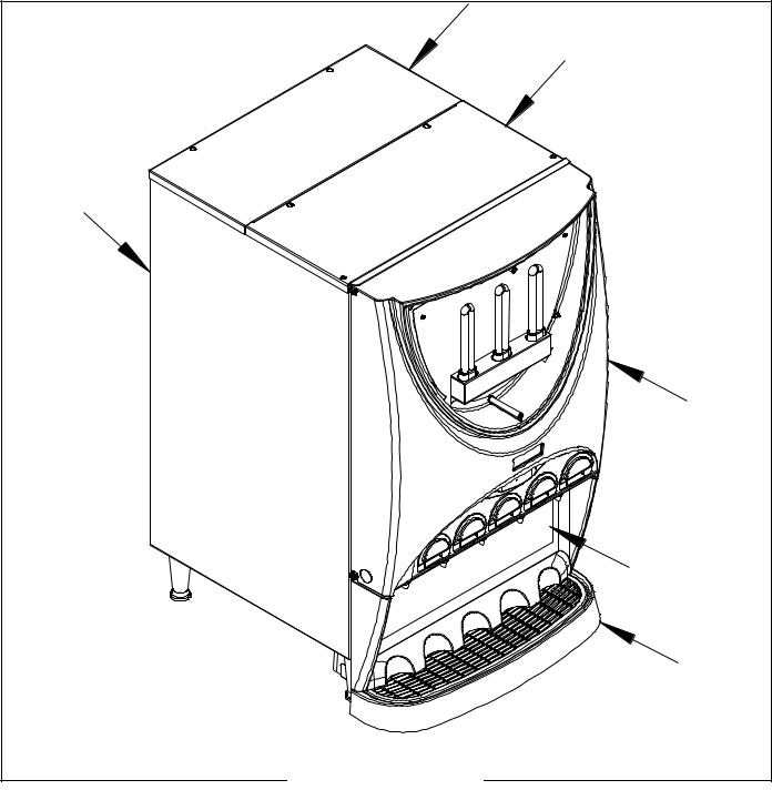
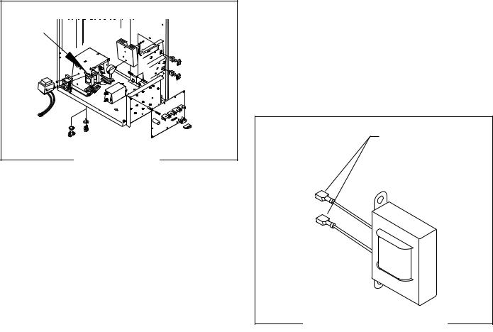
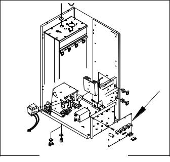
ACCESS PANELS
Location:
All access panels are similar through the whole IMIX family (IMIX-5 shown). Before removing panels, make sure power is OFF to the machine and water is disconnected accept where indicated in testing procedures. Retain all screws and other attaching hardware for re-assembly.
FIG. 1 ACCESS PANELS |
|
12 |
42032 060109 |
|
SERVICE(CONT.) |
|
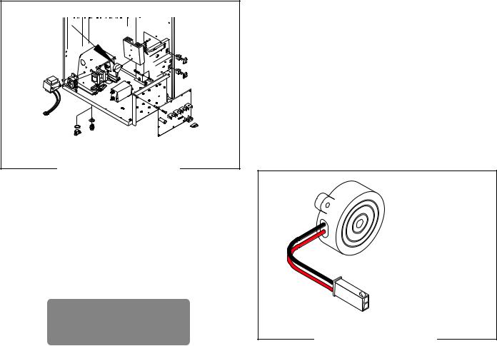
AUDIO INDICATOR (IMIX-3, 4 & 5 only) |
|
FIG. 2 AUDIO INDICATOR |
P3250.25 |
|
|
BEEPER |
|
Location:
The BEEPER is located on the back side of the component bracket assembly.
Test Procedures:
1.Enter Programming to verify the “Audible Alarm” is activated. It will always beep when pressing switches during program modes.
AUDIBLE ALARM ?
NO EXIT YES
If activated, verify it is plugged correctly into J8 on the control board.
Removal and Replacement:
1.Disconnect the dispenser from power.
2.Disconnect the two pin connector from J8 of the main control board.
3.Loosen two screws from underneath and remove the component mounting bracket.
4.Remove the two #6-32 screws attaching the Audio Indicator to the component mounting bracket.
5.Remove and discard the audio indicator.
6.Install new audio indicator using two #8-32 screws to secure indicator to the component bracket.
7.Refer to Fig. 3 when reconnecting the wires.
BLK to J8-1 |
|
on Control Board |
|
RED to J8-2 |
|
on Control Board |
|
FIG. 3 AUDIO INDICATOR |
P3250.25 |
|
|
BEEPER |
|
Specifications: |
|
SOUND PRESSURE LEVEL |
90 dBA |
RESONANT FREQUENCY |
2800 Hz |
RATED CURRENT |
7 mA |
RATED VOLTAGE |
12 VDC |
OPERATING VOLTAGE |
3 - 28 VDC |
13 |
42032 060109 |
|
SERVICE (CONT.)
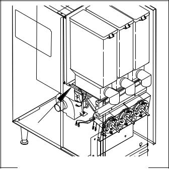
AUGER DRIVE COMPONENTS |
|
FIG. 4 AUGER DRIVE COMPONENTS |
P1341 |
|
Location:
The auger components are located inside the bottom part of the hopper except for the auger drive bracket, washer and locknut, which are located on the outside bottom rear of the hopper. The auger motors are located on the rear of the auger motor mounting panel. Refer to Fig. 5 for disassembly and assembly.
Test Procedures - Auger Motors without Proximity Sensor
1.Disconnect the dispenser from the power source.
2.Remove hoppers. Turn elbow up.
3.Back probe check the voltage across the positive and negative wire with a voltmeter. Connect the dispenser to the power supply. With the rinse/run switch in the run position press the appropriate dispense switch. After a .6 second delay the indication must be 4.0 to 24.5 volts dc.
4.Disconnect the dispenser from the power supply.
If voltage is present as described and the auger motor does not rotate, replace the auger motor.
If voltage is not present as described, refer to the wiring diagrams and check the dispenser wiring harness back to control board. Also verify 24 vac is supplied to control board from transformer - Refer to Control Board Testing.
Test Procedures - Auger Motors with Proximity Sensor. (IMIX only)
1.Open door and flip switch into PROGRAM mode.
2.Scroll to Diagnostics and select YES.
3.Scroll to Test Augers.
4.Press the appropriate dispense switch to activate motor. Refer to Diagnostics for further direction.
Removal, Cleaning and Replacement:
Hopper & Auger:
1.Open the dispenser door and turn elbow up.
2.Lift the front edge of hopper assy over the tab on hopper support plate (16) and slide hopper assembly out the front of the dispenser.
3.Remove hopper lid (1) and empty product.
4.Pull off the ejector elbow (10).
5.Remove agitator disk assy (2) by pushing out on the side of the hopper, rotating the agitator disk assy out of the mounting hubs and lifting the agitator disk assy from the hopper. Remove the mixing blades (4) from the agitator disk by tugging sharply.
6.Remove auger (9) by pulling it out the front of the hopper (8).
7.Remove the auger drive bracket by turning it clockwise while holding the auger drive shaft firmly.
8.Slide auger drive shaft (5) from auger drive shaft bushing (3) and remove from hopper (8).
9.Remove locknut (7) from auger drive shaft bushing (3) and remove auger drive shaft bushing from hopper (8).
10.Wash components in a mild solution of dish detergent using a bristle brush when needed.
11.Rinse and dry each item thoroughly.
12.Check for damaged or broken components, replace any if necessary and reassemble hopper assembly.
13.Install hopper assy in the dispenser by sliding hopper assy in the guides on the hopper support plate (16) until the slot in the bottom rear the hopper seats against the shoulder screw (15) in the hopper support plate.
14 |
42032 060109 |
|

SERVICE (CONT.)
AUGER DRIVE COMPONENTS
|
|
|
1 |
|
|
|
4 |
|
|
|
2 |
|
|
|
3 |
|
|
|
5 |
|
6 |
17 |
8 |
|
|
||
18 |
|
|
16 |
|
|
|
|
|
|
|
9 |
11 |
12 |
7 |
10 |
|
|
|
|
15 |
|
|
|
13 |
14 |
|
|
|
|
|
P2210.30 |
FIG. 5 AUGER DRIVE & HOPPER DISASSEMBLY |
|||
1. |
Hopper Lid |
10. |
Ejector Elbow |
2. |
Agitator Disk Assy |
11. |
Auger Motor Mount- |
3. |
Auger Drive Shaft |
ing Panel |
|
|
Bushing |
12. |
Auger Drive Coupling |
4. |
Mixing Blade |
13. |
Auger Motor |
5. |
Auger Drive Shaft |
14. |
Dust Seal |
6. |
Auger Shaft Coupling |
15. |
Shoulder Screw |
7. |
Locknut |
16. |
Hopper Support plate |
8. |
Hopper |
17. |
Coupling Spring |
9. |
Auger Wire |
18. |
Hex Coupling |
Auger Drive Motor (Refer to Figs. 5 thru 9)
1.Remove all hopper assemblies and set aside for reassembly.
2.Remove the four #8-32 screws securing the hopper support plate (16) and set aside for reassembly.
3.Remove the #8-32 locking screws, located inside the dispenser housing on the front of the auger motor mounting panel (11), securing auger motor
(13)to the rear of the auger motor mounting panel
4.Disconnect the wires from the auger motor (13) to be removed.
5.Disconnect RPM sensor plug.
6.Remove auger motor (13) and dust seal (14) as an assembly.
7.Remove dust seal (14) from auger motor (13).
8.Remove the #8-32 screws securing the auger motor to the auger motor mounting bracket.
9.Remove auger motor and discard.
10.Using #8-32 screws, install new auger motor (13) on mounting bracket (11).
11.Install dust seal (14) on auger motor shaft.
12.Using #8-32 locking screws install auger motor and dust seal to the rear of the auger motor mounting panel (11)
13.Reconnect the wires to the terminals on the auger motor.
14.Reconnect RPM sensor plug.
15.Install hopper support plate (16) and all hopper assemblies.
16.Refer to Fig. 6 when reconnecting wires.
BLK (-) |
RED (+) |
4-24 VDC
P1639
FIG. 6 AUGER MOTOR TERMINALS
15 |
42032 060109 |
|
SERVICE (CONT.) |
|
|
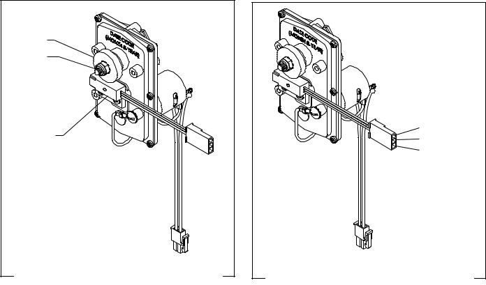
AUGER MOTOR PROXIMITY RPM SENSOR (IMIX-3, 4 & 5 only) |
||
MAGNET |
|
|
NUT & |
|
|
LOCKWASHER |
|
|
PROXIMITY |
BLK - COMMON |
|
GRN - SIGNAL |
||
SENSOR |
||
RED - +5VDC |
||
|
||
FIG. 7 AUGER MOTOR PROXIMITY SENSOR |
FIG. 8 PROXIMITY SENSOR TERMINALS |
|
Location:
The Proximity Sensor and Magnet are located on the back side of the Auger Motor assembly.
Test Procedures:
1.Ensure the the nut and lockwasher are tightened securely to prevent the Magnet from slipping, which causes a false reading when testing.
2.With a voltmeter, back probe the RED and BLK wires. The indication should be +5VDC.
3.Back probe the BLK and GRN wires. The indication should be an alternating reading of 5-0-5-0VDC. With power ON, the reading will actually fluctuate in the 3VDC range.
If voltage is present as described, the Proximity RPM Sensor is operating properly.
Removal and Replacement:
1.Disconnect the dispenser from the power source.
2.Disconnect the three pin connector from the main wirring harnes of the motor being serviced.
3.Remove the #10 nut and lockwasher securing the magnet hub to the auger motor shaft.
4.Remove the two #4-40 screws securing the sensor to the auger motor housing.
5.Remove and discard faulty parts.
6.Install a new sensor to the motor housing using the two #4-40 screws.
7.Install a new magnet hub using the #10 lockwasher and nut. Tighten the nut securely to prevent the magnet from slipping.
8.Connect the three pin connector to the dispenser main wiring harness.
16 |
42032 060109 |
|
SERVICE (cont.)
BALLAST |
P3250.25 |
FIG. 9 BALLAST |
Location: |
The front door lamp ballasts are located behind the front access panel and may be on either side of the component bracket assembly.
Test Procedure:
1.Disconnect the dispenser from the power source.
2.Disconnect the two black leads on the ballast from the dispenser main harness.
3.Check for continuity between the two black leads on the ballast.
If continuity is present as described the ballast is operating properly.
If continuity is not present as described, replace the ballast.
Removal and Replacement:
1.Disconnect the wires from the ballast.
2.Remove the two #8-32 screws securing the ballast to the component bracket.
3.Remove and discard ballast.
4.Install new ballast using two #8-32 screws to secure ballast to the component bracket.
5.Refer to Fig. 10 when reconnecting the wires.
BLK to Main Wiring |
|
Harness |
|
FIG. 10 BALLAST TERMINALS |
P1447 |
|
17 |
42032 060109 |
|
SERVICE (cont.)
CONTROL BOARD (IMIX-3, 4 & 5 only) |
P3250.25 |
FIG. 11 CONTROL BOARD |
Location:
The Control Board is located behind the lower front access cover mounted on the component bracket.
Test Procedure:
Power Supply Circuitry:
1.Disconnect the dispenser from the power source.
2.With a voltmeter, back probe check the voltage across pins 4 & 5 of the J2 connector on the wiring harness. Connect the dispenser to the power source. The indication must be 24 volts ac.
3.Disconnect the dispenser from the power source.
If voltage is present as described, proceed to step 4. If voltage is not present as described, refer to the Wiring Diagrams and check the dispenser wiring harness back to the transformer (See TRANSFORMER).
4.With a voltmeter, back probe check the voltage across pins 3 & 4 of the J1 connector on the wiring harness. Connect the dispenser to the power source. The indication must be:
a)120 volts ac for two wire 120 volt models, three wire 120/208 volt and 120/240 volt models.
b)240 volts ac for two wire 240 volt models.
c)230 volts ac for two wire 230 volt models.
5.Disconnect the dispenser from the power source.
If voltage is present as described, proceed to step 9. If voltage is not present as described, refer to the Wiring Diagrams and check the dispenser wiring harness back to the power cord. Also check for an open float switch.
Liquid Level Control Circuitry:
6.Gently pull the liquid level probe out of the tank lid and inspect for corrosion. Replace it if necessary.
7.Place the probe so that neither end is in contact with any metal surface of the dispenser.
8.With a voltmeter, check the voltage across J1 pins 4 and 8 on the control board. Connect the dispenser to the power source. The indication must be:
a)120 volts ac for two wire 120 volt models, three wire 120/208 volt and 120/240 volt models,
b)240 volts ac for two wire 240 volt models,
c)230 volts ac for two wire 230 volt models, after a delay of approximately 10 seconds.
9.Move the probe’s flat end to the dispenser housing. The indication must be 0.
10.Move the probe’s flat end away from the housing. The indication must, again, be:
a)120 volts ac for two wire 120 volt models, three wire 120/208 volt and 120/240 volt models,
b)240 volts ac for two wire 240 volt models,
c)230 volts ac for two wire 230 volt models, after a delay of approximately 5 seconds.
11.Disconnect the dispenser from the power source.
If the voltage is present as described, re-install the probe. The liquid level control circuitry is operating properly.
If the voltage is not present as described, check the pink probe wire and green tank wire for continuity.
18 |
42032 060109 |
|
 Loading...