

Page 1

PARTS REFERENCE LIST
MODEL: PT-9200DX
Page 2
NOTES FOR USING THIS PARTS REFERENCE LIST
1. In the case of ordering parts, it needs mentioning the following items:
(1) Code
(2) Q'ty
(3) Description
(4) Symbol (PCB No., Revision , and Parts location mounted on the PCB.)
Note : No orders without Parts Code or Tool No. can be accepted.
[ Example ]
(4) (1) (2) (3)
REF. NO.
SYMBOL CODE Q’TY DESCRIPTION REMARKS
Revision No. : marked on the printed circuit board.
B55L082 - 2 01 A
Design change indication
Specification No.
Pattern alteration No.
Circuit board No.
2. Design-changed parts:
When the parts are changed, any one of the following symbols is indicated in the REMARKS column.
CHNG#A : compatible between old and new
CHNG#B : replaceable from old to new
CHNG#D : incompatible
ADD : newly established
3. The original of this list was made based on the information available in September, 2000.
4. Parts are subject to change in design without prior notice.
Page 3

CONTENTS
1 . PRINT MECHANISM ................................................................................1
2 . COVERS .................................................................................................. 3
3 . MAIN PCB................................................................................................5
4 . SENSORS................................................................................................7
5 . POWER SUPPLY PCB .............................................................................7
6 . PRINTED MATTER .................................................................................. 9
7 . ATTACHMENTS.....................................................................................11
8 . PACKING MATERIALS........................................................................... 11
Page 4
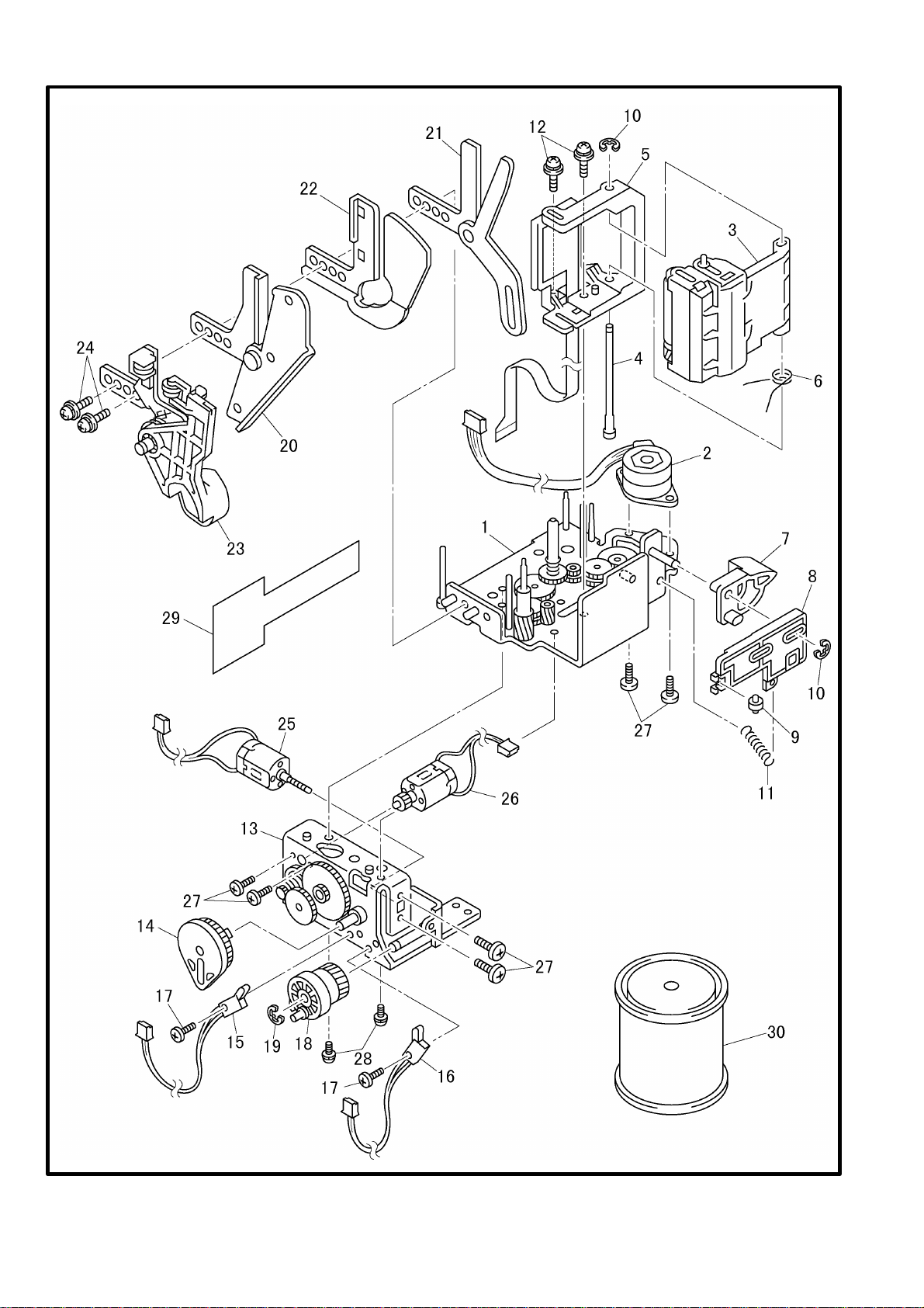
1 . PRINT MECHANISM
MODEL PT-9200DX 5V2-602-045/940
-1-
Page 5
1 . PRINT MECHANISM
REF.NO. CODE Q'TY DESCRIPTION REMARKS
1 LA2072001 1 MAIN FRAME PP ASSY
2 Z26599001 1 TAPE FEED MOTOR, BP242516M12-PP
3 LA2066001 1 ROLLER HOLDER ASSY PP (SP)
4 UT0895001 1 ROLLER HOLDER SHAFT
5 LA2071001 1 HEAD ASSY KSH384 BW3 (SP)
6 UT0901001 1 ROLLER HOLDER RELEASE SPRING
7 UT0902001 1 RELEASE CAM
8 UT0903001 1 ROLLER RELEASE ROD
9 UB5507000 1 RELEASE ROD ROLLER
10 048025346 2 RETAINING RING, E2.5
11 UT0872001 1 RELEASE LEVER SPRING PP
12 0A4301005 2 SCREW, PAN (S/P WASHER) M3X10
13 UT0904001 1 HALF FRAME ASSY
14 UT0917001 1 HALF ROCK GEAR
15 UT0958001 1 HALF CUTTER SENSOR ASSY
16 UT0961001 1 FULL CUTTER SENSOR ASSY
17 UT0855001 2 SCREW, PAN M1.7X6
18 UT0918001 1 CUTTER HELICAL GEAR ASSY
19 048040346 1 RETAINING RING, E4
20 UT0921001 1 HALF CUTTER ASSY
21 UT0929001 1 CUTTER ASSY PP
22 UT0932001 1 HALF SPACER
23 UT1401001 1 EJECT UNIT ASSY
24 0A4401205 2 SCREW, PAN (S/P WASHER) M4X12
25 UT0933001 1 FULL CUTTER MOTOR ASSY
26 UT0934001 1 HALF CUTTER MOTOR ASSY
27 UB3848001 6 SCREW, PAN M2.6X3.5
28 0A3300605 2 SCREW, PAN WASHER M3X6D
29 U62189000 1 PLATEN PROTECT PAD
30 UN7937000 1 GREASE G501, 1KG
-2-
MODEL PT-9200DX 5V2-602-045/940
Page 6

2 . COVERS
MODEL PT-9200DX 5V2-602-061
-3-
Page 7

2 . COVERS
REF.NO. CODE Q'TY DESCRIPTION REMARKS
1 LA3674001 1 BODY COVER USB, GRAY1395
2 UT0937001 1 POWER SUPPLY SWITCH BUTTON
3 UT0938001 1 POWER SUPPLY ACTUATOR
4 UT0939001 1 CUT FEED BUTTON, BLUE6189
5 UT0940001 1 COVER LOCK BUTTON, GRAY1395
6 UT0941001 1 COVER BUTTON ACTUATOR
7 UT0942001 1 LOCK LEVER SPRING
8 LA3706001 1 CASSETTE COVER USB US, GRAY1463 (USA/CAN)
8 LA3714001 1 CASSETTE COVER USB EU, GRAY 1463 (AUS/CHE/CHN/DEU/DNK/ESP/FIN/FRA
/GBR/HKG/IRL/ISL/KOR/SWE/TWN/ZAF)
9 UT0944001 1 CASSETTE PRESSER, GRAY1395
10 UT0945001 1 CASSETTE SPRING
11 UT0995001 1 COVER LOCK ACTUATOR, GRAY1395
12 UT0996001 1 COVER LOCK SPRING
13 UT0946001 1 FRONT COVER PP US, GRAY1395
14 UT0947001 1 BOTTOM COVER PP US, GRAY1395
15 UT0948001 1 CASSETTE COVER BRACKET, GY1395
16 UT0997001 1 DAMPER RUBBER
17 UT0998001 1 COVER OPEN CAM
18 UT0949001 1 COVER OPEN SPRING
19 UT0951001 1 INLET BRACKET
20 UT0952000 1 SHIELD PLATE B
21 LA4539001 1 FG HARNESS ASSY USB
22 UT0955001 1 LOWER COVER, GRAY1395
23 UB4431001 2 LOWER FOOT
24 0A5400805 2 SCREW, PAN (S/P WASHER) M4X8
25 085271017 4 TAPTITE, BIND B M2.6X10
26 084311016 2 SCREW, FLAT B M3X10
27 085270815 15 TAPTITE, BIND B M2.6X8
28 UT0555001 1 FCC LABEL (USA/CAN)
29 LA3708001 1 MYLAR LABEL USB US
30A UT0577001 1 TAPE CAUTION LABEL PP US
30B UT0578001 1 TAPE CAUTION LABEL PP EC (AUS/CAN/CHE/CHN/DEU/DNK/ESP/FIN/FRA/GBR/
HKG/IRL/ISR/KOR/SWE/TWN/ZAF)
31 UH3297001 1 C-TICK MARK (AUS)
32 LJ4421001 1 MARKING LABEL N/S (CHE/DEU/DNK/ESP/FIN/FRA/GBR/IRL/ISR/SWE/ZAF)
-4-
MODEL PT-9200DX 5V2-602-061
Page 8

3 . MAIN PCB
MODEL PT-9200DX 5V2-602-101
-5-
Page 9

3 . MAIN PCB
REF.NO. SYMBOL CODE Q'TY DESCRIPTION REMARKS
1 B55L082-201B LA3832001 1 MAIN PCB ASSY USB (SP)
-6-
MODEL PT-9200DX 5V2-602-101
Page 10

4 . SENSORS
MODEL PT-9200DX 5V2-602-100
5 . POWER SUPPLY PCB
MODEL PT-9200DX 5V2-602-102
-7-
Page 11

4 . SENSORS
REF.NO. SYMBOL CODE Q'TY DESCRIPTION REMARKS
1 B55L025-1 LA3833001 1 SUB PCB ASSY USB (SP)
2 B55L026-1 LA3834001 1 SENSOR PCB ASSY USB (SP)
3 B55L028-1 LA3835001 1 TAPE END SENSOR ASSY USB (SP)
4 UT0830001 1 INLET ASSY PP
MODEL PT-9200DX 5V2-602-100
5 . POWER SUPPLY PCB
REF.NO. SYMBOL CODE Q'TY DESCRIPTION REMARKS
1 MPW1533 UT0843001 1 PS PCB ASSY, 100-120V (SP) (USA/CAN/TWN)
1 MPW1433 UT0844001 1 PS PCB ASSY, 230V (SP) (AUS/CHE/CHN/DEU/DNK/ESP/FIN
/FRA/GBR/HKG/IRL/ISR/KOR/SWE/ZAF)
2 UT0837001 1 RELAY HARNESS ASSY
-8-
MODEL PT-9200DX 5V2-602-102
Page 12

6 . PRINTED MATTER
MODEL PT-9200DX 5V2-602-920
-9-
Page 13

6 . PRINTED MATTER
REF.NO. SYMBOL CODE Q'TY DESCRIPTION REMARKS
1 LA3710001 1 USER’S MANUAL USB US (USA)
1 LA3717001 1 USER’S MANUAL USB EC (CHE/DEU/DNK/ESP/FIN/FRA/GBR
/IRL/ISR/SWE/ZAF)
1 LA4484001 1 USER’S MANUAL USB CA (CAN)
1 LA4493001 1 USER’S MANUAL USB ASIA (AUS/CHN/HKG/KOR/TWN)
2A A LA4058001 1 WARRANTY CARD US JP (USA)
2B B UH3851001 1 WARRANTY CARD EUR (CHE/DEU/DNK/ESP/FRA/GBR/IRL
/SWE)
2C B UN8607001 1 WARRANTY CARD, CAN.E/F (CAN)
2D UB3650001 1 WARRANTY CARD, FRENCH (FRA)
2E LE5115001 1 WARRANTY CARD SWE-A (SWE)
2F UU0605001 1 WARRANTY CARD, SPA (ESP)
2G UH3662001 1 WARRANTY CARD UK-A (GBR)
2H UH3663001 1 WARRANTY CARD UK-B (GBR)
2I E UF4238001 1 WARRANTY CARD, HK (HKG)
2J LA1999001 1 WARRANTY CARD PP, TAIWAN (TWN)
3A B UT0325001 1 TAPE CATALOG US (USA)
3A UT0326001 1 TAPE CATALOG CA (CAN)
3A B UN4605001 1 TZ TAPE CATALOG, AUS (AUS/CHN/HKG)
3B A UN4239001 1 TAPE CATALOG UK (CHE/DEU/DNK/ESP/FIN/FRA/GBR/IRL
/ISR/SWE/ZAF)
4 UT0535001 1 UNPACKING INSTRUCTION PP
5 A LA1825001 1 ACCESSORY ORDER FORM, US (USA)
-10-
MODEL PT-9200DX 5V2-602-920
Page 14

7 . ATTACHMENTS
MODEL PT-9200DX 5V2-602-910
8 . PACKING MATERIALS
MODEL PT-9200DX 5V2-602-930
-11-
Page 15

7 . ATTACHMENTS
REF.NO. SYMBOL CODE Q'TY DESCRIPTION REMARKS
1A UH1051001 1 AC CORD, UL/CSA (USA/CAN/TWN)
1B UK4094001 1 AC CORD, DEMKO (DNK)
1C UH1055001 1 AC CORD, SAA (AUS)
1D UH1054001 1 AC CORD, BS (GBR/HKG/IRL)
1E UH1052001 1 AC CORD, VDE (DEU/ESP/FIN/FRA/KOR/SWE)
1F U34322001 1 AC CORD #6, ISRAEL (ISR)
1G U34320001 1 AC CORD #4, BS (ZAF)
1H UH1053001 1 AC CORD, SEV (CHE)
2 LA3677001 1 RS I/F CABLE WIN/MAC #2
3 LA3700001 1 USB I/F CABLE
4 LA3709001 1 CD-ROM ASSY USB US (USA)
4 LA4483001 1 CD-ROM ASSY USB CA (CAN)
4 LA3716001 1 CD-ROM ASSY USB EC (CHE/DEU/DNK/ESP/FIN/FRA/GBR/IRL
/ISR/SWE/ZAF)
4 LA4492001 1 CD-ROM ASSY USB ASIA (AUS/CHN/HKG/KOR/TWN)
5 UT0267001 1 LETTERING STICK TZ36 (CHE/CHN/DEU/DNK/ESP/FIN/FRA
/GBR/HKG/IRL/ISR/KOR/SWE/ZAF)
MODEL PT-9200DX 5V2-602-910
8 . PACKING MATERIALS
REF.NO. CODE Q'TY DESCRIPTION REMARKS
1 LA3711001 1 CARTON USB US (USA)
1 LA3718001 1 CARTON USB EC (CHE/DEU/DNK/ESP/FIN/FRA/GBR/IRL/ISR/SWE/ZAF)
1 LA4485001 1 CARTON USB CA (CAN)
1 LA4494001 1 CARTON USB ASIA (AUS/CHN/HKG/KOR/YWN)
2 UT0894001 1 STYROFOAM PAD PP
3 UT0895001 1 BAG, 250X600H (BODY)
4 UT0594001 1 BAG, 130X350 (AC CORD)
5 UN5224001 1 BAG, 215X360H (USER’S MANUAL)
6 UT0596001 1 STYROFOAM PAD B
7 UT0597001 1 CORRUPAD PP
8 LA4535001 1 PAD
-12-
MODEL PT-9200DX 5V2-602-930
Page 16

Sep., 2000
5V2105BE0
Printed in Japan
 Loading...