

Page 1

Brother PJ-600/700 Series Command Reference
PJ-600/700 Series Printer
Raster Command Reference
PJ-622/623/662/663/673
722/723/763/763MFi/773
2015-11-2 Version 1.2
Brother Industries, Ltd.
© 2015 Brother Industries, Ltd. All Rights Reserved.
Page 2

Brother PJ-600/700 Series Command Reference
1. Introduction .............................................................................................................. 1
2. Overview ................................................................................................................. 2
3. Print Data ................................................................................................................ 3
3.1. Print data overview ......................................................................................... 3
3.2. Page data details ........................................................................................... 5
4. Status .................................................................................................................... 13
4.1. Overview .................................................................................................... 13
4.2. Definitions of each part ................................................................................... 14
5. Command ............................................................................................................... 18
5.1. Overview .................................................................................................... 18
5.2. Command details .......................................................................................... 19
5.3. Utility Command details ................................................................................... 28
5.4. Returned data for retrieve commands .................................................................. 45
6. Flow Charts ............................................................................................................. 48
6.1. USB/Bluetooth/IrDA Printing flow ....................................................................... 49
7. USB Specifications .................................................................................................... 51
8. Compatibility and Support Information ............................................................................. 52
8.1. Compatibility with PJ-500 series printers .............................................................. 52
8.2. Inquiry ........................................................................................................ 52
© 2015 Brother Industries, Ltd. All Rights Reserved.
Page 3

Brother PJ-600/700 Series Command Reference
1
1. Introduction
This material provides the necessary information for directly controlling the Brother PJ-600 series
printer (hereafter, referred to as “PJ unit”). This information is provided assuming that the user has full
understanding of the operating system being used and basic mastery of USB/Bluetooth/IrDA and
networks in a developer’s environment.
Details concerning the USB interface are not described in this material. If a USB interface is being
used, refer to “7. USB Specifications” to prepare the interface.
We accept no responsibility for any problems caused by programs that you develop using the
information provided in this material, affecting software, data or hardware, including the Brother PJ unit,
and any problems resulting directly or indirectly from them. These materials are provided in their current
condition, and we assume no responsibility for their content. Use this material only if you accept these
terms.
This material shall not be reproduced, in part or in full, without prior approval. In addition, this material
shall not be used as evidence in a lawsuit or dispute in a way that is unfavorable towards our company.
© 2015 Brother Industries, Ltd. All Rights Reserved.
Page 4

Brother PJ-600/700 Series Command Reference
2
2. Overview
The printing procedure is described below. For detailed flow charts, refer to “6. Flow Charts” For details
on each command, refer to “5. Command”.
1. Open USB/Bluetooth Serial/IrDA/Network port
Open the USB/Bluetooth Serial/IrDA/network port in the operating environment. In addition, since the
procedure for opening the USB port is not described in this material, perform the appropriate operation
for the environment being used.
2. Check machine status
The “Status information request” command is sent to the printer, the status information received from the
printer is analyzed, and then the status of the printer is determined. For details on the “Status information
request” command and on the definition of “status”, refer to “4. Status” in “Command Reference”.
Printing is possible if the analysis results show that the following conditions are met.
・ Paper compatible with the print data is installed in the printer.
・ No error has occurred.
This step is not necessary with a unidirectional transmission.
3. Send print data
The print data is sent. The structure of the print data is explained in the next section, “3. Print Data”.
4. Confirmation of printing completion
When printing is completed, the status is sent from the printer. This status is analyzed and, if printing is
completed, one page is printed. If the print job has multiple pages, 2 through 4 are repeated.
In addition, the status is not sent with a unidirectional transmission.
5. Close USB/Bluetooth Serial/IrDA/Network port
After all printing is finished, close the port.
© 2015 Brother Industries, Ltd. All Rights Reserved.
Page 5
Brother PJ-600/700 Series Command Reference
3
Sequence
Command Name
Description/Example
1
Invalid command 700
bytes
Sends the “invalid” command to the PJ unit, then clears
raster data remaining in the unit.
00 H, 00 H, 00 H, … ,00 H
2
Switch command mode
Switches the command mode of the PJ unit.
1B H , 69 H , 61 H , 00 H
3
Initialize
Initializes the print buffer.
1B H , 40 H
4
Set 2-ply mode
To specify the disable setting for 2-ply paper:
1B H , 7E H , 70 H , 00 H
5
Set density
Specifies the print density. To set the density to 5:
1B H, 7E H, 64 H, 80 H, 00H
6
Set form feed mode
Specifies the operation that is performed when the “Form
Feed” command is received.
To feed according to the paper size specified with the
“Set paper height” command (step 9):
1B H, 7E H, 66 H, 01 H
7
Set dash line print
To turn off printing of the dashed line:
1B H, 7E H, 2D H, 00 H
8
Set paper width
Specifies the paper width. For A4 on a 300 dpi model:
1B H, 7E H, 77 H, 2C H, 01 H
9
Set paper height
Specifies the paper size. For A4 on a 300 dpi model:
1B H, 7E H, 68 H, E4 H, 0C H
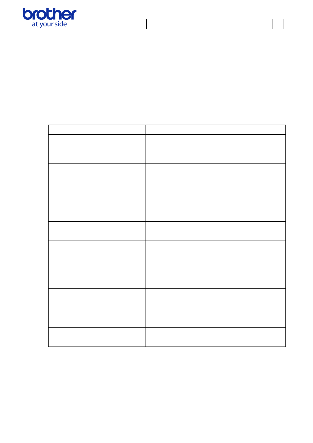
3. Print Data
3.1. Print data overview
The print data is constructed of the following: ① Initialization data, ② Printing commands and ③ Print
command. If the print job consists of multiple pages, ② through ③ are repeated.
1. Initialization data
The beginning of the job is specified only once.
*If an unlimited length or custom paper size is selected, use “Set paper length” command in step 9.
© 2015 Brother Industries, Ltd. All Rights Reserved.
Page 6
Brother PJ-600/700 Series Command Reference
4
Sequence
Command Name
Description/Example
-
Set left margin
Moves the cursor the specified distance from the left
edge of the printable area in the X direction.
1B H, 7E H, 24 H, {n1}, {n2}
-
1 Raster line data
transfer
Sends the raster line data.
To send 300 bytes of data:
1B H, 7E H, 2A H, 2C H, 01 H, FF H, FF H….
-
Multi-line feed
Terminates raster line data and feeds 1 or more lines.
1B H, 7E H, 4A H, {n1}
Sequence
Command Name
Description/Example
-
Form feed
Specifies the end of a page.
1BH, 7EH, 0CH
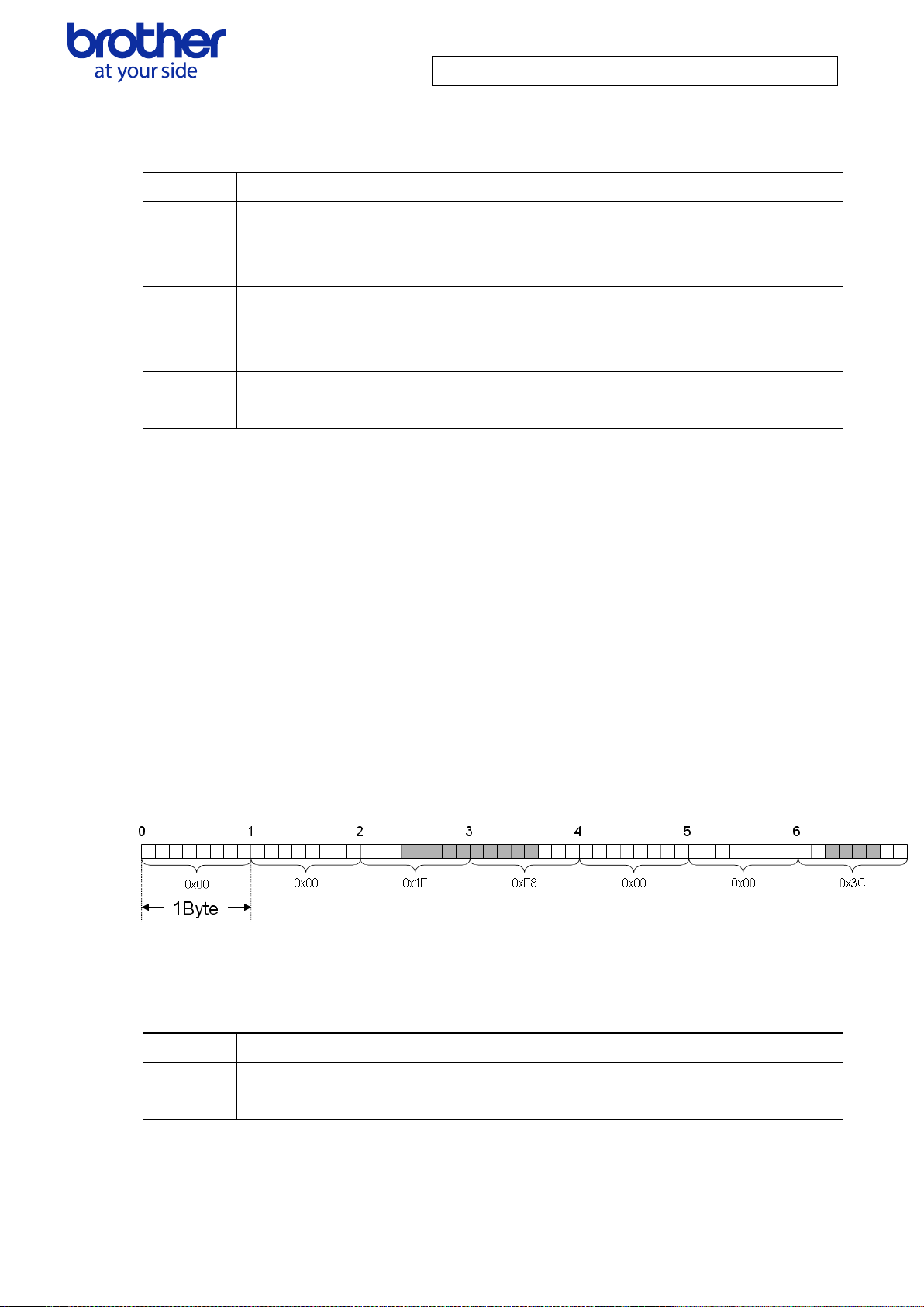
2. Printing commands
Repeat for each raster line in the print job.
Note:
“Set left margin” and “1 Raster line data transfer” commands can be sent more than once per line
Example: The raster line data shown below can be sent with the following commands.
In addition, it is recommended that the “set left margin” command be used when a blank space extends
for 16 bytes or more.
Set left margin: 1BH, 7EH, 24H, 10H, 00H
Raster line data transfer: 1BH, 7EH, 2AH, 02H, 00H, 1FH, F8H
Set left margin: 1BH, 7EH, 24H, 30H, 00H
Raster line data transfer: 1BH, 7EH, 2AH, 01H, 00H, 3CH
Multi-line feed: 1BH, 7EH, 4AH, 01H
3. Print command
Specified at the end of the page.
© 2015 Brother Industries, Ltd. All Rights Reserved.
Page 7

Brother PJ-600/700 Series Command Reference
5
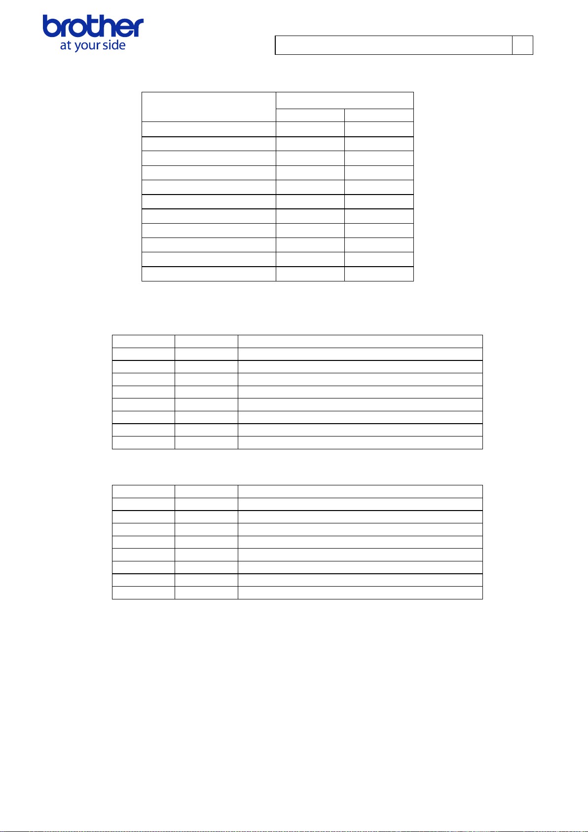
Model
Resolution
200 dpi (PJ-622/662/722/762)
300 dpi
(PJ-623/663/673/723/763/763MFi/773)
203 dpi in main scan direction,
200 dpi in secondary scan direction
300 dpi in main scan direction,
300 dpi in secondary scan direction
3.2. Page data details
Information on the values for the printed page size is provided below.
3.2.1. Resolution
© 2015 Brother Industries, Ltd. All Rights Reserved.
Page 8
Brother PJ-600/700 Series Command Reference
6
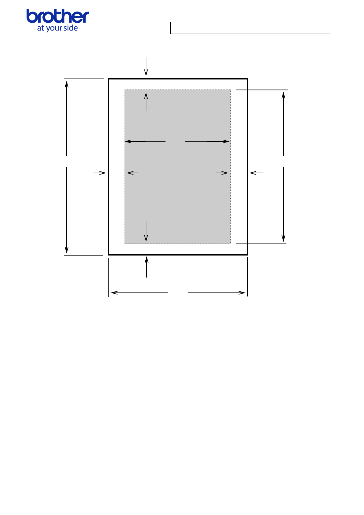
3.2.2. Page size (300 dpi model)
B
G
A C
F H
D
E
A: Length B: Top margin
C: Printable area length D: Bottom margin
E: Width F: Left margin
G:Printable area width H: Right margin
© 2015 Brother Industries, Ltd. All Rights Reserved.
Page 9
Brother PJ-600/700 Series Command Reference
7
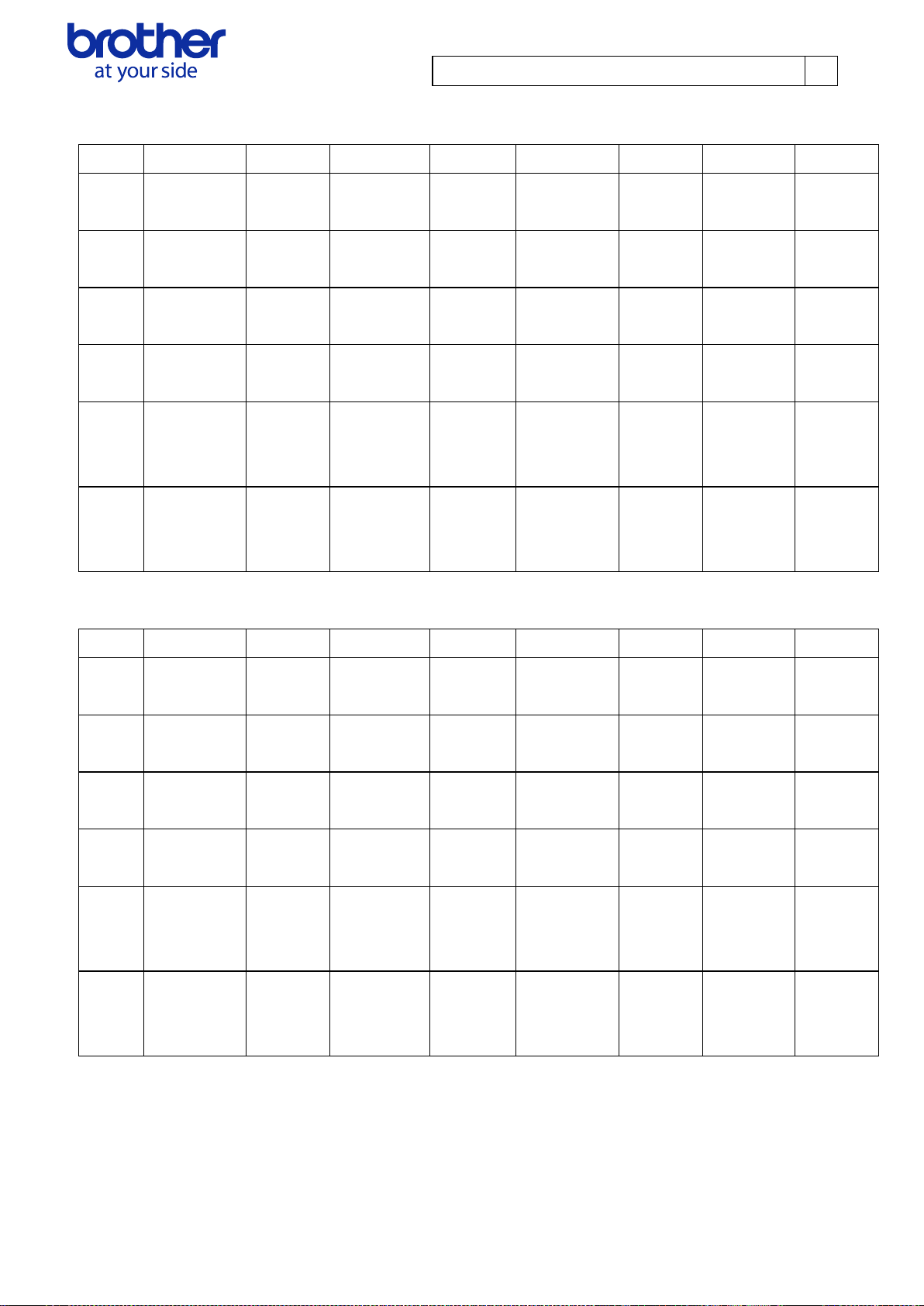
Paper A B C D E F G H
A4
297.0 mm
3507 dots
2.5 mm
30 dots
279.4 mm
3300 dots
15.0 mm
177 dots
210.0 mm
2480 dots
3.4 mm
40 dots
203.2 mm
2400 dots
3.4 mm
40 dots
Legal
355.6 mm
4200 dots
2.5 mm
30 dots
347.1 mm
4100 dots
5.9 mm
70 dots
215.9 mm
2550 dots
3.6 mm
43 dots
208.6 mm
2464 dots
3.6 mm
43 dots
Letter
279.4 mm
3300 dots
2.5 mm
30 dots
270.9 mm
3200 dots
5.9 mm
70 dots
215.9 mm
2550 dots
3.6 mm
43 dots
208.6 mm
2464 dots
3.6 mm
43 dots
A5
210.0mm
2480 dots
2.5 mm
30 dots
193.8 mm
2289 dots
13.6 mm
161 dots
148.0 mm
1748 dots
3.4 mm
40 dots
141.2 mm
1668 dots
3.4 mm
40 dots
Custom
Size
Min
50.8 mm
600 dot
2.5 mm
30 dots
42.3 mm
500 dots
5.9 mm
70 dots
101.6 mm
1200 dot
3.4 mm
40 dots
94.8 mm
1120 dots
3.4 mm
40 dots
Custom
Size
Max
2540.0 mm
30000 dot
2.5 mm
30 dots
2531.5 mm
29900 dots
5.9 mm
70 dots
215.9 mm
2550 dot
3.4 mm
40 dots
208.6 mm
2464 dot
3.9 mm
46 dots
Paper A B C D E F G H
A4
297.0 mm
3507 dots
11.9 mm
140 dots
279.1 mm
3297 dots
5.9 mm
70 dots
210.0 mm
2480 dots
3.4 mm
40 dots
203.2 mm
2400 dots
3.4 mm
40 dots
Legal
355.6 mm
4200 dots
11.9 mm
140 dots
337.8 mm
3990 dots
5.9 mm
70 dots
215.9 mm
2550 dots
3.6 mm
43 dots
208.6 mm
2464 dots
3.6 mm
43 dots
Letter
279.4 mm
3300 dots
11.9 mm
140 dots
261.6 mm
3090 dots
5.9 mm
70 dots
215.9 mm
2550 dots
3.6 mm
43 dots
208.6 mm
2464 dots
3.6 mm
43 dots
A5
210.0mm
2480 dots
11.9 mm
140 dots
192.2 mm
2270 dots
5.9 mm
70 dots
148.0 mm
1748 dots
3.4 mm
40 dots
141.2 mm
1668 dots
3.4 mm
40 dots
Custom
Size
Min
50.8 mm
600 dots
11.9 mm
140 dots
33.0 mm
390 dots
5.9 mm
70 dots
101.6 mm
1200 dots
3.4 mm
40 dots
94.8 mm
1120 dots
3.4 mm
40 dots
Custom
Size
Max
2540.0 mm
30000 dots
11.9 mm
140 dots
2522.2 mm
29790 dots
5.9 mm
70 dots
215.9 mm
2550 dots
3.4 mm
40 dots
208.6 mm
2464 dots
3.9 mm
46 dots
・Fixed length
*When the paper type is set to “cut sheet” or “perforated roll retract”
*When the paper type is set to “roll”
© 2015 Brother Industries, Ltd. All Rights Reserved.
Page 10
Brother PJ-600/700 Series Command Reference
8
Paper A B C D E F G H
A4
297.0 mm
3507 dots
11.9 mm
140 dots
268.9 mm
3177 dots
16.1 mm
190 dots
210.0 mm
2480 dots
3.4 mm
40 dots
203.2 mm
2400 dots
3.4 mm
40 dots
Legal
355.6 mm
4200 dots
11.9 mm
140 dots
327.6 mm
3870 dots
16.1 mm
190 dots
215.9 mm
2550 dots
3.6 mm
43 dots
208.6 mm
2464 dots
3.6 mm
43 dots
Letter
279.4 mm
3300 dots
11.9 mm
140 dots
251.4 mm
2970 dots
16.1 mm
190 dots
215.9 mm
2550 dots
3.6 mm
43 dots
208.6 mm
2464 dots
3.6 mm
43 dots
A5
210.0mm
2480 dots
11.9 mm
140 dots
182.0 mm
2150 dots
16.1 mm
190 dots
148.0 mm
1748 dots
3.4 mm
40 dots
141.2 mm
1668 dots
3.4 mm
40 dots
Custom
Size
Min
50.8 mm
600 dots
11.9 mm
140 dots
22.9 mm
270 dots
16.1 mm
190 dots
101.6 mm
1200 dots
3.4 mm
40 dots
94.8 mm
1120 dots
3.4 mm
40 dots
Custom
Size
Max
2540.0 mm
30000 dots
11.9 mm
140 dots
2512.0 mm
29670 dots
16.1 mm
190 dots
215.9 mm
2550 dots
3.4 mm
40 dots
208.6 mm
2464 dots
3.9 mm
46 dots
*When the paper type is set to “perforated roll”
© 2015 Brother Industries, Ltd. All Rights Reserved.
Page 11

Brother PJ-600/700 Series Command Reference
9
Paper
A B C D E F G
H
A4
297.0 mm
2338 dots
2.5 mm
20 dots
279.4 mm
2200 dots
15.0 mm
118 dots
210.0 mm
1654 dots
3.4 mm
27 dots
203.2 mm
1600 dots
3.4 mm
27 dots
Legal
355.6 mm
2800 dots
2.5 mm
20 dots
347.1 mm
2733 dots
6.0 mm
47 dots
215.9 mm
1700 dots
4.3 mm
34 dots
207.2 mm
1632 dots
4.3 mm
34 dots
Letter
279.4 mm
2200 dots
2.5 mm
20 dots
270.9 mm
2133 dots
6.0 mm
47 dots
215.9 mm
1700 dots
4.3 mm
34 dots
207.2 mm
1632 dots
4.3 mm
34 dots
A5
210.0 mm
1653 dots
2.5 mm
20 dots
193.8 mm
1526 dots
13.6 mm
107 dots
148.0 mm
1165 dots
3.4 mm
27 dots
141.1 mm
1111 dots
3.4 mm
27 dots
Custom
Size Min
50.8 mm
400 dots
2.5 mm
20 dots
42.2 mm
333 dots
6.0 mm
47 dots
101.6 mm
800 dots
3.4 mm
27 dots
94.7 mm
746 dots
3.4 mm
27 dots
Custom
Size
Max
2540.0 mm
20000 dots
2.5 mm
20 dots
2531.4 mm
19933 dots
6.0 mm
47 dots
215.9 mm
1700 dots
3.4 mm
27 dots
207.2 mm
1632 dots
5.2 mm
41 dots
Paper
A B C D E F G
H
A4
297.0 mm
2338 dots
10.9 mm
93 dots
280.0 mm
2198 dots
6.0 mm
47 dots
210.0 mm
1654 dots
3.4 mm
27 dots
203.2 mm
1600 dots
3.4 mm
27 dots
Legal
355.6 mm
2800 dots
10.9 mm
86 dots
338.7 mm
2667 dots
6.0 mm
47 dots
215.9 mm
1700 dots
4.3 mm
34 dots
207.2 mm
1632 dots
4.3 mm
34 dots
Letter
279.4 mm
2200 dots
10.9 mm
86 dots
262.5 mm
2067 dots
6.0 mm
47 dots
215.9 mm
1700 dots
4.3 mm
34 dots
207.2 mm
1632 dots
4.3 mm
34 dots
A5
210.0 mm
1653 dots
10.9 mm
86 dots
193.0 mm
1520 dots
6.0 mm
47 dots
148.0 mm
1165 dots
3.4 mm
27 dots
141.1 mm
1111 dots
3.4 mm
27 dots
Custom
Size Min
50.8 mm
400 dots
10.9 mm
86 dots
33.9 mm
267 dots
6.0 mm
47 dots
101.6 mm
800 dots
3.4 mm
27 dots
94.7 mm
746 dots
3.4 mm
27 dots
Custom
Size
Max
2540.0 mm
20000 dots
10.9 mm
86 dots
2523.1 mm
19867 dots
6.0 mm
47 dots
215.9 mm
1700 dots
3.4 mm
27 dots
207.2 mm
1632 dots
5.2 mm
41 dots
3.2.3. Page size (200 dpi model)
・Fixed length
*When the paper type is set to “cut sheet” or “perforated roll retract”
*When the paper type is set to “roll”
© 2015 Brother Industries, Ltd. All Rights Reserved.
Page 12
Brother PJ-600/700 Series Command Reference
10
Paper
A B C D E F G
H
A4
297.0 mm
2338 dots
10.9 mm
86 dots
269.0 mm
2118 dots
17.0 mm
134 dots
210.0 mm
1654 dots
3.4 mm
27 dots
203.2 mm
1600 dots
3.4 mm
27 dots
Legal
355.6 mm
2800 dots
10.9 mm
86 dots
327.7 mm
2580 dots
17.0 mm
134 dots
215.9 mm
1700 dots
4.3 mm
34 dots
207.2 mm
1632 dots
4.3 mm
34 dots
Letter
279.4 mm
2200 dots
10.9 mm
86 dots
251.5 mm
1980 dots
17.0 mm
134 dots
215.9 mm
1700 dots
4.3 mm
34 dots
207.2 mm
1632 dots
4.3 mm
34 dots
A5
210.0 mm
1653 dots
10.9 mm
86 dots
182.0 mm
1433 dots
17.0 mm
134 dots
148.0 mm
1165 dots
3.4 mm
27 dots
141.1 mm
1111 dots
3.4 mm
27 dots
Custom
Size Min
50.8 mm
400 dots
10.9 mm
86 dots
22.9 mm
180 dots
17.0 mm
134 dots
101.6 mm
800 dots
3.4 mm
27 dots
94.7 mm
746 dots
3.4 mm
27 dots
Custom
Size
Max
2540.0 mm
20000 dots
10.9 mm
86 dots
2512.0 mm
19780 dots
17.0 mm
134 dots
215.9 mm
1700 dots
3.4 mm
27 dots
207.2 mm
1632 dots
5.2 mm
41 dots
*When the paper type is set to “perforated roll”
© 2015 Brother Industries, Ltd. All Rights Reserved.
Page 13
Brother PJ-600/700 Series Command Reference
11
0 pin
Paper
margin
First byte
Raster line
Feeding
direction
Print area
Pins
on print
head
Number of
print area
pins
Number
of unused
pins
Total number of pins
Number
of offset
pins
Paper
Number of
offset pins
Number of
Print area pins
Number of
unused pins
A4
96
2400
96
Legal
64
2464
64
Letter
64
2464
64
A5
462
1668
462
Paper
Number of
offset pins
Number of
Print area pins
Number of
unused pins
A4
64
1600
64
Legal
48
1632
48
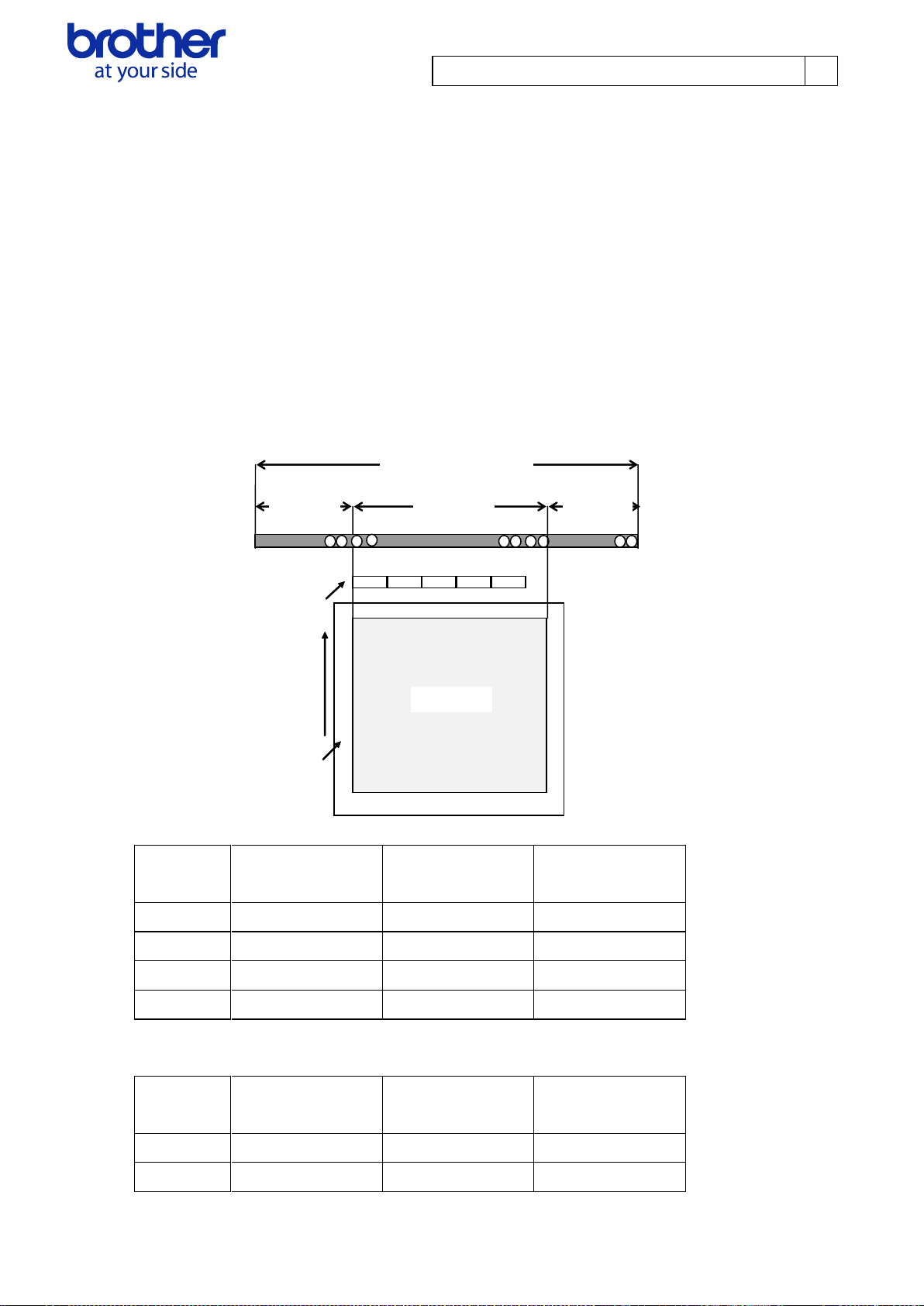
3.2.4. Raster line
The following shows how the raster is arranged on the pins of the print head according to "raster
graphics transfer".
The number of offset pins is calculated automatically based on the “set paper width” command and
centering the print area across the print head
The raster data specified with the “set left margin” and “1 raster line data transfer” commands is
reflected in the pins of the print area.
Furthermore, specified print data that extends out of the print area is automatically cut by the unit. In
addition, the page margins (in all directions) in the figure shown below have no effect on the raster
line.
Total number of pins (300dpi) 2592
Total number of pins (200dpi) 1728
© 2015 Brother Industries, Ltd. All Rights Reserved.
Page 14

Brother PJ-600/700 Series Command Reference
12
Letter
48
1632
48
A5
309
1111
308
© 2015 Brother Industries, Ltd. All Rights Reserved.
Page 15
Brother PJ-600/700 Series Command Reference
13
Number
Offset
Size
Name
Value/Reference
1 0 1
Print head mark
Fixed to “80 Hex”
2 1 1
Size
Fixed to “20 Hex”
3 2 1
Reserved
Fixed to ’B’ (42 Hex)
4 3 1
Series code
Refer to section 4.2.1.
5 4 1
Model code
Refer to section 4.2.1.
6 5 1
Reserved
Fixed to '0' (30 Hex)
7 6 1
Reserved
Fixed to “00 Hex”
8 7 1
Reserved
Fixed to “00 Hex”
9 8 1
Error information 1
Refer to section 4.2.2.
10 9 1
Error information 2
Refer to section 4.2.2.
11
10
1
Paper width
Refer to section 4.2.3.
12
11
1
Paper loaded
Refer to section 4.2.4.
13
12
1
Reserved
Fixed to “00 Hex”
14
13
1
Reserved
Fixed to “00 Hex”
15
14
1
Reserved
Fixed to “00 Hex”
16
15
1
Reserved
Fixed to “00 Hex”
17
16
1
Reserved
Fixed to “00 Hex”
18
17
1
Paper Length(Lower order
bytes)
Refer to section 4.2.4.
19
18
1
Status type
Refer to section 4.2.5.
20
19
1
Phase type
Refer to section 4.2.6.
21
20
1
Higher order bytes of phase
number
Refer to section 4.2.6.
22
21
1
Lower order bytes of phase
number
Refer to section 4.2.6.
23
22
1
Notification number
Refer to section 4.2.7.
24
23
1
Reserved
Fixed to “00 Hex”
25
24
8
Reserved
Fixed to “00 Hex”
4. Status
4.1. Overview
The status is sent from the printer to the computer as a reply to the "status information request"
command or as an error message. The size is fixed to 32 bytes.
© 2015 Brother Industries, Ltd. All Rights Reserved.
Page 16
Brother PJ-600/700 Series Command Reference
14
Model name
Status code
Series
Model
PJ-622
‘6’ (0x36)
‘1’ (0x31)
PJ-623
‘6’ (0x36)
‘2’ (0x32)
PJ-662
‘6’ (0x36)
‘3’ (0x33)
PJ-663
‘6’ (0x36)
‘4’ (0x34)
PJ-673
‘6’ (0x36)
‘5’ (0x35)
PJ-722
‘6’ (0x36)
‘6’ (0x36)
PJ-723
‘6’ (0x36)
‘7’ (0x37)
PJ-762
‘6’ (0x36)
‘8’ (0x38)
PJ-763
‘6’ (0x36)
‘9’ (0x39)
PJ-763MFi
‘6’ (0x36)
‘A’ (0x41)
PJ-773
‘6’ (0x36)
‘B’ (0x42)
Flag
Mask
Definition
Bit 0
0x01
Not used
Bit 1
0x02
Page finished (only while printing)
Bit 2
0x04
Not used
Bit 3
0x08
Charging required
Bit 4
0x10
Not used
Bit 5
0x20
Not used
Bit 6
0x40
Not used
Bit 7
0x80
Not used
Flag
Mask
Definition
Bit 0
0x01
Not used
Bit 1
0x02
Not used
Bit 2
0x04
Not used
Bit 3
0x08
Not used
Bit 4
0x10
Not used
Bit 5
0x20
Not used
Bit 6
0x40
Not used
Bit 7
0x80
Not used
4.2. Definitions of each part
4.2.1. Series/model
4.2.2. Error information 1 and error information 2
Error information 1
Error information 2
© 2015 Brother Industries, Ltd. All Rights Reserved.
Page 17

Brother PJ-600/700 Series Command Reference
15
Paper loaded
Value
No paper
00 Hex
Paper
01 Hex
4.2.3. Paper width and length
Paper width:
No paper: 0x00
Paper: 0xD2
Paper length:
Fixed to “0x00”
4.2.4. Paper loaded
© 2015 Brother Industries, Ltd. All Rights Reserved.
Page 18

Brother PJ-600/700 Series Command Reference
16
Status Type
Value
Reply to status request
00 Hex
Printing completed
01 Hex
Error occurred
02 Hex
Notification
05 Hex
Phase change
06 Hex
Phase Type
Value
Receiving state
00 Hex
Printing state
01 Hex
Phase Number
Value
(Dec)
Higher
Order
Bytes
Lower
Order
Bytes
Waiting to receive
0
00 Hex
00 Hex
Phase Number
Value
(Dec)
Higher
Order
Bytes
Lower
Order
Bytes
Printing
0
00 Hex
00 Hex
4.2.5. Status type
4.2.6. Phase type and phase number
If the phase type and phase number are not used, both are fixed to “00 Hex”.
Receiving state
Printing state
© 2015 Brother Industries, Ltd. All Rights Reserved.
Page 19

Brother PJ-600/700 Series Command Reference
17
Notification
Value
Invalid
00 Hex
Cooling (started)
03 Hex
Cooling (finished)
04 Hex
4.2.7. Notification number
© 2015 Brother Industries, Ltd. All Rights Reserved.
Page 20

Brother PJ-600/700 Series Command Reference
18
5. Command
5.1. Overview
This chapter provides descriptions of the commands that can be interpreted by the PJ unit.
Section 5.2 provides descriptions of the commands used for printing in Raster mode. See section
3.1 for typical Print Data Sequence.
Section 5.3 provides descriptions of the commands for default printer settings and ESC/P mode.
© 2015 Brother Industries, Ltd. All Rights Reserved.
Page 21

Brother PJ-600/700 Series Command Reference
19
Name
Invalid command
Syntax
NULL
00 H
Description
Skip
If data transmission should be stopped midway, send the “initialize” command after
sending the “invalid” command for the appropriate number of bytes to return to the
receiving state, where the print buffer is cleared.
Name
Switch command mode
Syntax
ESC + i + a + {n1}
1B H + 69 H + 61 H + {n1}
Description
Switches between the machine's command modes. A machine that receives this
command operates in the specified command mode until the machine is turned off.
Definition of {n1}:
0:ESC/P・Raster (default)
1: Maintenance Mode
3:P-touch Template
Name
Initialize
Syntax
ESC + @
1B H + 40 H
Description
Initializes the print buffer.
Name
Status information request
Syntax
ESC + i + S
1B H + 69 H + 53 H
Description
Status information is transmitted.
Name
Set 2-ply mode
Syntax
ESC + ~ + p + {n1} + null
1B H + 7E H + 70 H + {n1} + 00 H
Description
Specifies whether or not the strobe time is extended and the print density is adjusted
when 2-ply paper is used.
Definition of {n1}:
0:Disable (default)
1:Enable
5.2. Command details
© 2015 Brother Industries, Ltd. All Rights Reserved.
Page 22

Brother PJ-600/700 Series Command Reference
20
Name
Bidirectional transmission mode
Syntax
ESC + ~ + e + D + {n1}
1B H + 7E H + 65 H + 44 H + {n1}
Description
When bidirectional transmission is enabled, the printer returns the “printing completed”
status when printing is finished. In addition, if an error occurred during printing, all print
data received for those pages is discarded.
Definition of {n1}:
0: Disable (default)
1: Enable
*Replies with a “status information request” command even if bidirectional transmission
is disabled.
Name
Set density
Syntax
ESC + ~ + d + {n1} + null
1B H + 7E H + 64 H + {n1} + 00 H
Description
Specifies the print density.
Note: Print density may differ from the conditions, such as the type of thermal paper,
print pattern, environment, etc. Please set the appropriate density.
Definition of {n1}: 0 to 255
The lower the parameter value, the lower the density becomes.
Parameter n1 Density amount
0 (00 H) ~ 23 (17 H) 0
24 (18 H) ~ 47 (2F H) 1
48 (30 H) ~ 71 (47 H) 2
72 (48 H) ~ 95 (5F H) 3
96 (60 H) ~ 119 (77 H) 4
120 (78 H) ~ 143 (8F H) 5
144 (90 H) ~ 167 (A7 H) 6
168 (A8 H) ~ 191 (BF H) 7
192 (C0 H) ~ 215 (D7 H) 8
216 (D8 H) ~ 239 (EF H) 9
240 (F0 H) ~ 255 (FF H) 10
© 2015 Brother Industries, Ltd. All Rights Reserved.
Page 23

Brother PJ-600/700 Series Command Reference
21
Name
Set print speed
Syntax
ESC + ~ + e + V + 01 + {n1}
1B H + 7E H + 65 H + 56H + 01H + {n1}
Description
Specifies the print speed.
Note: Print density may differ from the conditions, such as the type of thermal paper,
print pattern, environment, etc. Please set the appropriate density.
Definition of {n1}
0 : 2.5 ips (65mm/s)
1 : 1.9ips (48mm/s)
2 : 1.6 ips (41 mm/s)
3 : 1.1 ips (27 mm/s)
Name
Set roll printer case setting
Syntax
ESC + ~ + e + R + 01 + {n1}
1B H + 7E H + 65 H + 52H + 01H + {n1}
Description
Specifies the feed setting when using roll printer case.
Definition of {n1}
0 : None
1 : PA-RC-001 (Without Anti Curl)
2 : PA-RC-001
Name
Set form feed mode
Syntax
ESC + ~ + f + {n1}
1B H + 7E H + 66 H + {n1}
Description
Specifies the operation that is performed when the “Form Feed” command is received.
Definition of {n1}:
0:No Feed
1:Fixed Page (default)
2:End of Page
3:End of Page Retract
[Details]
No Feed:
A page feed is not performed, even if the “Form Feed” command is received.
Fixed Page:
The page is fed the number of lines specified with the “set paper height” or “set
paper length” command.
© 2015 Brother Industries, Ltd. All Rights Reserved.
Page 24

Brother PJ-600/700 Series Command Reference
22
End of Page:
The paper is fed until the end of the page is detected. However, this is a maximum
of 14 inches.
End of Page Retract:
The paper is fed until the end of the page is detected, and then the paper is
readjusted to the starting position.
Name
Set dash line print
Syntax
ESC + ~ + - + {n1}
1B H + 7E H + 2D H + {n1}
Description
Specifies whether or not a dotted line is printed between pages when the user sets the
paper type to “roll” and the form feed mode to “Fixed page”.
Definition of {n1}:
0:Disable (default)
1:Enable
© 2015 Brother Industries, Ltd. All Rights Reserved.
Page 25

Brother PJ-600/700 Series Command Reference
23
Name
Set paper height
Syntax
ESC + ~ + h + {n1} + {n2}
1B H + 7E H + 68 H + {n1} + {n2}
Description
Specifies the paper size. The default setting is Letter size.
The 2-byte data for pre-defined paper sizes is sent as the values for {n1} and {n2}.
―300dpi―
Paper Size Letter A4 Legal
Value 3200 3300 4100
(n1, n2) (80 H, 0C H) (E4 H, 0CH) (04 H, 10 H)
―200dpi―
Paper Size Letter A4 Legal
Value 2133 2200 2733
(n1, n2) (55 H, 08 H) (98 H, 08H) (AD H, 0A H)
© 2015 Brother Industries, Ltd. All Rights Reserved.
Page 26

Brother PJ-600/700 Series Command Reference
24
Name
Set paper width
Syntax
ESC + ~ + w + {n1} + {n2}
1B H + 7E H + 77 H + {n1} + {n2}
Description
Specifies the paper width.
※The selection method is different for custom paper and for non-custom paper.
■Non-custom paper
The units of the data are in bytes.
Example: For A4, the number of dots for the print area is 2400, so 300 is set.
Ex. 1B H 7E H 77 H 2C H 01 H
→A4 setting (300)
■Custom paper
Specify the width according to the feed position, as shown below.
With [Center Alignment]
Specify, in bytes, the number of dots for the width of the print area.
Example: For a 140-mm-wide print area, the number of dots for the print area is 1654,
so 207 is set.
Ex.1BH 7EH 77H CFH 00H
With [Left Alignment]
Specify as fixed, regardless of the paper width, as shown below.
300dpi: 1BH 7EH 77H 34H 01H
200dpi: 1BH 7EH 77H CCH 00H
Name
Set paper length
Syntax
ESC + ~ + l + {n1} + {n2}
1B H + 7E H + 6C H + {n1} + {n2}
Description
Specifies the paper length.
Normally used with roll paper or custom lengths.
The setting range is 200 to 65535 (raster lines).
Ex. 1B h 7E H 6C H E4 H 0C H
→The length of the print area is set to 3300.
Name
Set left margin
Syntax
ESC + ~ + $ + {n1} + {n2}
© 2015 Brother Industries, Ltd. All Rights Reserved.
Page 27

Brother PJ-600/700 Series Command Reference
25
1B H + 7E H + 24 H + {n1} + {n2}
Description
Moves the cursor the specified distance from the left edge of the printable area in the X
direction.
The setting is a 2-byte value, and the units are in bits.
Since the sent data is specified in bytes, it is treated as a multiple of 8.
If it is not a multiple of 8, the nearest value at a multiple of 8 is specified.
Ex) 1B H 7E H 24 H 44 H 00 H
44 H = 68 However, since it is treated as bytes, the setting becomes 64.
© 2015 Brother Industries, Ltd. All Rights Reserved.
Page 28

Brother PJ-600/700 Series Command Reference
26
Name
Multi-line feed
Syntax
ESC + ~ + J + {n1}
1B H + 7E H + 4A H + {n1}
Description
Terminates current raster line and performs a line feed of multiple raster lines on the
current page.
Definition of {n1}: Number of lines
This command is used in connection with the “1 raster line data transfer” command.
After raster line data is transferred, the line buffer data is deleted, and then the current
print position in the X direction remains the same while the print position is moved in the
Y direction by the number of lines specified with {n1}.
Ex) 1B H 7E H 4A H 03 H
Performs a line feed of 3 lines.
Name
1 Raster line data transfer
Syntax
ESC + ~ + * + {n1} + {n2} + {d1} + ... + {dk}
1B H + 7E H + 2A H + {n1} + {n2} + {d1} + ... + {dk}
Description
Sends the raster line data.
Definition of {n1} and {n2}:
Amount of data to be sent (Specified in units of bytes.)
Definition of {d1} + ... + {dk}:
Raster line data
The data print position specified with this command is for the current position of the
current raster line.
If more than 1 "Raster line data transfer" command is sent for the same raster line, the
data cannot be positioned to the left of the final raster byte already sent for this raster
line.
Ex) 1B H 7E H 2A H 2C H 01 H FF H FF H ...
300 bytes = Sends raster line data for 2400 dots
© 2015 Brother Industries, Ltd. All Rights Reserved.
Page 29

Brother PJ-600/700 Series Command Reference
27
Name
Form feed
Syntax
ESC + ~ + FF
1B H + 7E H + 0C H
Description
Prints the current page and ejects according to the setting of the “set form feed mode”
command.
Using this command, cursor position is automatically reset to left edge.
If no data is received for the current page, this command is ignored.
© 2015 Brother Industries, Ltd. All Rights Reserved.
Page 30

Brother PJ-600/700 Series Command Reference
28
Name
Specify page length in lines
Syntax
ESC + C + {n1}
1B H + 43 H + {n1}
Description
Specifies the page length as ((line feed amount when this command is specified)
* (n in lines)) inches.
In addition, when this command is executed, the bottom margin is set to 0
(canceled).
Definition of {n1}:01 H ~ 7F H(1~127)
・Basic page length settings (in lines) for each paper size and line feed
6LPI 8LPI/0.125 8LPI/0.12
Letter 66 88 91
Legal 84 112 116
A4 70 93 97
Name
Specify bottom margin
Syntax
ESC + N + {n1}
1B H + 4E H + {n1}
Description
Specify the size of the bottom margin.
Definition of {n1}:01 H ~ 7F H(1~127)
The units are in lines.
・Basic bottom margin settings for each paper size and line feed
6LPI 8LPI/0.125 8LPI/0.12
Letter 2 3 2
Legal 2 3 2
A4 2 3 2
5.3. Utility Command details
Note: These commands are primarily for setting power-on default values for printer
specific settings and for printing text-only data.
© 2015 Brother Industries, Ltd. All Rights Reserved.
Page 31

Brother PJ-600/700 Series Command Reference
29
Name
Specify line feed of 1/6 inch
Syntax
ESC + 2
1B H + 32 H
Description
Specify line feed of 1/6 inch (6LPI).
The line feed becomes 1/6 inch.
After this command is specified, the page length in lines and bottom margin must
be specified again.
Name
Specify line feed of 1/8 inch
Syntax
ESC + 0
1B H + 30 H
Description
Specify line feed of 1/8 inch (8LPI).
The line feed becomes 1/8 inch.
After this command is specified, the page length in lines and bottom margin must
be specified again.
Name
Line feed at 8 LPI
Syntax
ESC + ~ + + + {n1}
1B H + 7E H + 2B H + {n1}
Description
Specify whether the line feed is “0.125"” or “0.12"” when the line feed is set to 1/8
inch.
You can use this command to allow extended ASCII graphic characters to touch
each other without creating a small vertical gap between the characters.
After this command is specified, the page length in lines and bottom margin must
be specified again.
Definition of {n1}
01 H(1) or 1F H(31) :0.120 inch Line feed
Other than those listed above :0.125 inch Line feed
© 2015 Brother Industries, Ltd. All Rights Reserved.
Page 32

Brother PJ-600/700 Series Command Reference
30
Name
Specify left margin
Syntax
ESC + l + {n1}
1B H + 6C H + {n1}
Description
Specifies the left margin position as the position from the left edge where
(character width when this command is specified) * n1, and specifies the area to
the left of this as an unprinted area.
Character width = 1 / Default pitch.
In addition, this printer operates as an 80-column device, and a setting that
extends past 4.5 inches from the left edge is ignored.
Definition of {n1}:01 H(1) ~ FF H(255)
The units are in columns.
Name
Specify right margin
Syntax
ESC + Q + {n1}
1B H + 51 H + {n1}
Description
Specifies the rightt margin position as the position from the left edge where
(character width when this command is specified) * n1,.
Character width = 1 / Default pitch.
Setting that extends past 8.0 inches from the left edge and that is less than left
margin is ignored.
Note that the setting indicates the value from left edge.
Definition of {n1}:01 H(1) ~ FF H(255)
Name
Specify Default pitch
Syntax
ESC + M + {n1}
1B H + 4D H + {n1}
Description
Select the character size (pitch).
After this command is specified, the left margin and right margin must be
specified again.
Definition of {n1}
00 H(0):10cpi
01 H(1):12cpi
02 H(2):15cpi
© 2015 Brother Industries, Ltd. All Rights Reserved.
Page 33

Brother PJ-600/700 Series Command Reference
31
Name
Apply/cancel proportional characters
Syntax
ESC + p + {n1}
1B H + 70 H + {n1}
Description
Applies or cancels proportional characters for alphanumeric characters.
After this command is specified, the left margin and right margin must be
specified again.
Definition of {n1}
00 H(0): Cancel proportional characters
01 H(1): Apply proportional characters
Name
Auto-on/off
Syntax
ESC + ~ + A + {n1}
1B H + 7E H + 41 H + {n1}
Description
Select whether or not the print unit is automatically turned on when it is plugged
into an external power supply.
Definition of {n1}:
00 H(0):Disable
01 H(1):Enable
02 H(2):Enable(No main button)
Name
Specify Auto Power Off(AC/DC/Li-ion)
Syntax
ESC + ~ + e + t + {n1} + NUL
1B H + 7E H + 65 H + 74 H + {n1} + 00 H
Description
Select the length of time until the print unit automatically turns off when it is
plugged into an external power supply.
Definition of {n1}:
00 H(0):None
01 H(1):10 minutes
02 H(2):20 minutes
03 H(3):30 minutes
04 H(4):40 minutes
05 H(5):50 minutes
06 H(6):60 minutes
© 2015 Brother Industries, Ltd. All Rights Reserved.
Page 34

Brother PJ-600/700 Series Command Reference
32
Name
Specify Auto Power Off(Ni-MH)
Syntax
ESC + ~ + t + {n1} + NUL
1B H + 7E H + 74 H + {n1} + 00 H
Description
Select the length of time until the print unit automatically turns off when it is only
using the Ni-MH rechargeable battery.
Definition of {n1}:
00 H(0):None
01 H(1):10 minutes
02 H(2):20 minutes
03 H(3):30 minutes
04 H(4):40 minutes
05 H(5):50 minutes
06 H(6):60 minutes
Name
Specify Refresh Battery
Syntax
ESC + ~ + B + {n1}
1B H + 7E H + 42 H + {n1}
Description
Select how frequently the refresh operation is performed when the Ni-MH
rechargeable battery is charged.
Definition of {n1}:
00 H(0): Do not refresh
01 H(1): Each time
02 H(2): Every 5 times
03 H(3): Every 10 times
© 2015 Brother Industries, Ltd. All Rights Reserved.
Page 35

Brother PJ-600/700 Series Command Reference
33
Name
Specify dash line print
Syntax
ESC + ~ + - + {n1}
1B H + 7E H + 2D H + {n1}
Description
Select whether or not a dotted line is printed as a perforation between pages. If
roll paper is being used and “Form Feed Mode” is set to “Fixed Page”, dotted
lines are printed between pages.
Definition of {n1}:
00 H(0):Disable
01 H(1):Enable
Name
Specify skip perforation
Syntax
ESC + ~ + P + {n1}
1B H + 7E H + 50 H + {n1}
Description
The bottom margin and the top margin of pages total 1 inch.
Definition of {n1}
00 H(0):Disable
01 H(1):Enable
Name
Specify Pre-Feed
Syntax
ESC + ~ + E + {n1}
1B H + 7E H + 45 H + {n1}
Description
Select whether or not to pre-feed paper that is in the unit when it is turned on.
Definition of {n1}:
00 H(0): Disable
01 H(1): Enable
© 2015 Brother Industries, Ltd. All Rights Reserved.
Page 36

Brother PJ-600/700 Series Command Reference
34
Name
Specify CR-LF mode
Syntax
ESC + ~ + L + {n1}
1B H + 7E H + 4C H + {n1}
Description
Select the operation mode for receiving a new line command.
Definition of {n1}:
00 H(0): LF = LF CR = CR
01 H(1): LF = CR + LF CR = CR + LF
Name
Specify Paper sensor threshold
Syntax
ESC + ~ + e + S + {n1}
1B H + 7E H + 65 H + 53 H + {n1}
Description
Specify the threshold for the sensor that detects the paper.
Definition of {n1}:
00 H(0) ~ FF H(255)
Name
BT/IrDA *Available only with PJ-662 and PJ-663.
Syntax
ESC + ~ + e + l + {n1}
1B H + 7E H + 65 H + 6C H + {n1}
Description
Select whether a Bluetooth or an IrDA connection is to be used.
Definition of {n1}
00 H(0):IrDA
01 H(1):Bluetooth
Name
Specify Wireless Switching Mode *Available only with PJ-662 and PJ-663.
Syntax
ESC + ~ + e + M + {n1}
1B H + 7E H + 65 H + 4D H + {n1}
Description
Select whether or not print unit buttons (Feed button + power button) can be
pressed to switch between using a Bluetooth or an IrDA connection.
Definition of {n1}:
00 H(0):Disable
01 H(1):Enable
© 2015 Brother Industries, Ltd. All Rights Reserved.
Page 37

Brother PJ-600/700 Series Command Reference
35
Name
Select Extended character code table
Syntax
ESC + t + {n1}
1B H + 74 H + {n1}
Description
Selects the character table for character codes 128 through 255.
Definition of {n1}:
00 H(0): Select italic characters
01 H(1): Select advanced graphics
Name
Select international character set
Syntax
ESC + R + {n1}
1B H + 52 H + {n1}
Description
Changes a part of the alphanumeric character code table.
Definition of {n1}:
00 H(0):USA
01 H(1):France
02 H(2):Germany
03 H(3):UK
04 H(4):Denmark
05 H(5):Sweden
06 H(6):Italy
07 H(7):Spain
08 H(8):Japan
09 H(9):Norway
0A H(10):Denmark II
0B H(11):Spain II
0C H(12):Latin America
0D H(13):Korea
40 H(64):Legal
© 2015 Brother Industries, Ltd. All Rights Reserved.
Page 38

Brother PJ-600/700 Series Command Reference
36
Name
Specify Default font
Syntax
ESC + k + {n1}
1B H + 6B H + {n1}
Description
Select the font to be used.
Definition of {n1}
00 H(0):Serif
01 H(1):Sans Serif
Name
Specify reduced characters
Syntax
ESC + 0x0F
1B H + 0F H
Description
The width of proportional characters is halved (10 cpi→16.67 cpi and 12 cpi →
20 cpi).
After this command is specified, the page length in lines and bottom margin must
be specified again.
In addition, the final character size when this command is executed and the
“specify double-width characters” is set becomes the size of the double-width
characters after they are reduced.
Name
Cancel reduced characters.
Syntax
ESC + 0x12
1B H + 12 H
Description
Cancels reduced characters
After this command is specified, the page length in lines and bottom margin must
be specified again.
Name
Apply bold style
Syntax
ESC + E
1B H + 45 H
Description
Applies the bold style to alphanumeric characters.
© 2015 Brother Industries, Ltd. All Rights Reserved.
Page 39

Brother PJ-600/700 Series Command Reference
37
Name
Cancel bold style
Syntax
ESC + F
1B H + 46 H
Description
Cancels the bold style.
Name
Specify/cancel double-width characters
Syntax
ESC + W + {n1}
1B H + 57 H + {n1}
Description
Specifies or cancels double-width enlargement for alphanumeric characters.
After this command is specified, the page length in lines and bottom margin must
be specified again.
In addition, the final character size when this command is executed and the
“Specify reduced characters” is set becomes the size of the double-width
characters after they are reduced.
Definition of {n1}
00 H(0):Disable
01 H(1):Enable
Name
Apply/cancel underlining
Syntax
ESC + - + {n1}
1B H + 2D H + {n1}
Description
Specifies or cancels underlining of alphanumeric characters.
Definition of {n1}
00 H(0):Disable
01 H(1):Enable
© 2015 Brother Industries, Ltd. All Rights Reserved.
Page 40

Brother PJ-600/700 Series Command Reference
38
Name
Specify/retrieve Bluetooth settings
*Available only with PJ-662 and PJ-663.
Syntax
ESC + ~ + e + B + {n1} + ・・・
1B H + 7E H + 65 H + 42 H + {n1} + ・・・
Description
Specifies or retrieves Bluetooth settings in the utility.
Definition of {n1}
00 H(0): Retrieve
01 H(1): Specify
…Additional
00 H(0):PIN Code(less than 16 characters)
01 H(1):Device Name(less than 30 characters)
02 H(2): Visible to Other Devices
00 H(0):Disable
01 H(1):Enable
03 H(3): Authentication and Encoding
00 H(0): No authentication/no encoding
01 H(1): Authentication/no encoding
02 H(2): Authentication/encoding
04 H(4): Retrieve BT address (*Invalid if “Specify” is set for {n1}.)
ex1) 1B H 7E H 65 H 42 H 01 H 00 H 04 H 0001
Specify PIN Code Number of characters
Setting
→Sets the PIN code to 0001.
ex2) 1B H 7E H 65 H 42 H 00 H 00 H
Retrieve PIN Code
→Retrieves the PIN code. (Reception example: 0x04 0001)
ex3) 1B H 7E H 65 H 42 H 01 H 01 H 0A H PJ-6630001
Specify Device Name Number of characters
Setting
→Sets the device name to PJ-6630001.
ex4) 1B H 7E H 65 H 42 H 00 H 01 H
Retrieve Device Name
→Retrieves the device name. (Reception example: 0x0A PJ-6630001)
© 2015 Brother Industries, Ltd. All Rights Reserved.
Page 41

Brother PJ-600/700 Series Command Reference
39
ex5) 1B H 7E H 65 H 42 H 01 H 02 H 00 H
Specify Visible to Other Devices Settings
→Sets that other devices cannot detect this machine (Disable).
ex6) 1B H 7E H 65 H 42 H 01 H 03 H 00 H
Specify Authentication and Encoding
Settings
→Sets that there is no authentication and encoding.
*The BT address is received at a fixed size of 6 bytes.
Name
Enter cleaning mode
Syntax
ESC + ~ + c + {n1} + NUL
1B H + 7E H + 63 H + {n1} + 00 H
Description
Sets the machine into cleaning mode.
Definition of {n1}:
01 H(1):ON
※To cancel cleaning mode, press the Feed button on the machine while it is in
cleaning mode.
Name
Print Unit Settings
Syntax
ESC + ~ + s + {n1} + NUL
1B H + 7E H + 73 H + {n1} + 00 H
Description
Sends the “print unit settings” command to the machine.
The machine that receives this command will print a page showing its current
settings
Definition of {n1}:
01 H(1):ON
© 2015 Brother Industries, Ltd. All Rights Reserved.
Page 42

Brother PJ-600/700 Series Command Reference
40
Name
Auto Adjust Sensor
Syntax
ESC + ~ + e + C + {n1}
1B H + 7E H + 65 H + 43 H + {n1}
Description
Automatically adjusts the threshold for the sensor that detects the paper. The
machine that receives this command feeds the paper and detects the black mark.
After this command is sent, notification of the results is returned as 2 bytes.
Definition of {n1}
01 H(1): Perform automatic adjustment
Notification of results
・First byte
00 H(0): Failed
01 H(1): Succeeded
・Second byte
Specified paper sensor threshold value if succeeded
ex) 1B H 7E H 65 H 43 H 01 H (perform automatic adjustment)
・Reception example of notification of results 1: 00 H
→Failed to perform automatic adjustment.
・Reception example of notification of results 2: 01 H 96 H
→Succeeded in performing automatic adjustment, and set the value to 150.
Name
Factory Reset
Syntax
ESC + ~ + R
1B H + 7E H + 52 H
Description
Returns the unit to its manufacturer default settings.
Overwrites the settings in both the non-volatile memory and RAM with the
manufacturer default settings.
If the current settings are the same as the manufacturer default settings, they are
not overwritten.
Then, the reset can be saved on the machine if the “initialize” command is sent.
© 2015 Brother Industries, Ltd. All Rights Reserved.
Page 43

Brother PJ-600/700 Series Command Reference
41
Name
Retrieve current settings (except Bluetooth settings)
Syntax
ESC + ~ + e + U + {n1}
1B H + 7E H + 65 H + 55 H + {n1}
Description
Retrieves the settings for the parameters that can be specified, except those
related to Bluetooth.
The data size (2 bytes) and data are returned from the machine.
The normal data size is 34 bytes.
For details on the data, refer to 5.4.
Definition of {n1}:
00 H(0): Host transmission
Name
Save settings
Syntax
ESC + ~ + S
1B H + 7E H + 53 H
Description
Saves the settings on the printer.
Overwrites them even if they are the same as those on the RAM and non-volatile
memory.
Name
Auto Power Off (AC/DC) 1 minute
Syntax
ESC + ~+ e + t + {n1} + 01h
Description
Specifies the amount of time that passes before the printer turns off automatically
when connected to an AC or DC power outlet.
Definition of {n1}
00h: None ~ 78h: 120 minutes
Name
Auto Power Off (Li-ion) 1 minute
Syntax
ESC + ~+ t + {n1} + 01h
Description
Specifies the amount of time that passes before the printer turns off automatically
when powered by the rechargeable Li-ion battery.
Definition of {n1}
00h: None ~ 78h: 120 minutes
5.3.1. PJ-700 Series Utility Command details
In this section, the Utility commands for only PJ-700 Series are listed.
© 2015 Brother Industries, Ltd. All Rights Reserved.
Page 44

Brother PJ-600/700 Series Command Reference
42
Name
Command Mode
Syntax
ESC + i + X + i + 2 + 01h + 00h + {n1}
Description
Specifies the printer’s command format.
Definition of {n1}
00 H(0): Raster
03 H(1): P-touch Template
04 H(2): ESC/P Brother
10 H(3): ESC/P Legacy
Name
Print Speed
Syntax
ESC + ~ + e + V + 01h + {n1}
Description
Specifies the printing speed in inches or millimeters per second.
Definition of {n1}
00 H(0): 2.5 ips / 65 mm/s
01 H(1): 1.9 ips / 48 mm/s
02 H(2): 1.6 ips / 41 mm/s
03 H(3): 1.1 ips / 27 mm/s
Name
Tear Adjust
Syntax
ESC + ~ + e + r + 01h + {n1}
Description
Adjust the tear bar tear off position for paper media.
Definition of {n1}
30h : +0.08" ~ 00h : 0" ~ D0h : -0.08"
Name
Roll Printer Case Setting
Syntax
ESC +~ + e + R + 01h + {n1}
Description
Specifies the setting for using the optional roll printer case.
Definition of {n1}
00h: Off
01h: On
02h: On (Without Anti Curl)
03h: On (Short Feed)
© 2015 Brother Industries, Ltd. All Rights Reserved.
Page 45

Brother PJ-600/700 Series Command Reference
43
Name
Print Length Scaling
Syntax
ESC + ^ + L + 01h + {n1}
Description
Specifies the reduction or enlargement ratio for printing.
Definition of {n1}
CEh : 95% ~ 00h : 100% ~ 32h : 105%
Name
Paper Grip Time
Syntax
ESC + ~ + e + F + 01h + {n1}
Description
Specifies the delay before the printer grabs the paper.
Definition of {n1}
05h : 0.5 seconds
08h : 0.8 seconds
0Ch : 1.2 seconds
Name
Print Data after Printing
Syntax
ESC + i + X + s + 32h + 00h + {n1}
Description
Allows to erase print data after it is printed.
Definition of {n1}
00h : Keep Print Data
01h : Erase All Print Data
Name
JPEG Printing Setting
Syntax
ESC + ~ + e + J + 01h + {n1}
Description
Specifies the JPEG printing setting.
Definition of {n1}
00h: Simple Binary
01h: Error Diffusion
Name
Scale JPEG images to fit media
Syntax
ESC + ~ + e + a + 01h + {n1}
Description
Allows enlarging or reducing a JPEG image to fit the paper size.
Definition of {n1}
00h: Disable
01h: Enable
© 2015 Brother Industries, Ltd. All Rights Reserved.
Page 46

Brother PJ-600/700 Series Command Reference
44
Name
Power Off Mode
Syntax
ESC + ~ + e + 6 + 01h + {n1}
Description
Choose how you want to turn off the printer.
Definition of {n1}
00h: Single press to turn off
01h: Double press to turn off
Name
Airplane Mode
Syntax
WiFi Model : ESC+ i + X + K + 2 + 00h + 00h + {n1}
Bluetooth Model : ESC+ i + X + B + 2 + 01h + 00h + 06h + {n1}
Description
Allows disabling the Bluetooth or Wi-Fi button. This function is useful when you
use the printer in a place where signal transmissions are not allowed.
Definition of {n1}
03h: On
04h: Off
Name
Reset only Device Settings
Syntax
ESC + i + U + Z
Description
Resets only the settings that can be specified using the PJ-700 Device Settings
to the factory settings.
Name
Delete Template
Syntax
ESC + i + U + Y
Description
Deletes all the templates stored in the printer.
© 2015 Brother Industries, Ltd. All Rights Reserved.
Page 47

Brother PJ-600/700 Series Command Reference
45
Name
Value
BYTE
0
Paper Size
Letter
A4
Legal
The values differ for the 200 dpi
and 300 dpi models.
2
2
Print Density
0x00 – 0xFF
1
3
Form Feed Mode
0x00:No Feed
0x01:Fixed Page
0x02:End of Page
0x03:End of Page Retract
1
4
Pre-Feed
0x00:Disable
0x01:Enable
1
5
CR-LF Mode
0x00:LF=LF CR=CR
0x01:LF=CR+LF CR=CR+LF
1
6
Paper Sensor Threshold
0x00 – 0xFF
1
7
BT/IrDA
0x00:IrDA
0x01:Bluetooth
1 8 Wireless Switching Mode
0x00:Disable
0x01:Enable
1
9
Auto-on
0x00:Disable
0x01:Enable
0x02:Enable+No main button
1
10
Auto Power Off(AC/DC/Li-ion)
0x00 – 0x06
(in 10-minute units)
1
11
Auto Power Off(Ni-MH)
0x00 – 0x06
(in 10-minute units)
1
12
Refresh Ni-MH Battery
0x00:Do not refresh
0x01:Each time
0x02:Every 5 times
0x03:Every 10 times
1
13
Dash line print
0x00:Disable
0x01:Enable
1
14
Line feed at 8 LPI
0x01 or 0x1F:0.120 inch line
feed
Other than those listed above:
0.125 inch line feed
1
15
Skip Perforation
0x00:Disable
0x01:Enable
1
5.4. Returned data for retrieve commands
© 2015 Brother Industries, Ltd. All Rights Reserved.
Page 48

Brother PJ-600/700 Series Command Reference
46
16
Default Pitch
0x00:10cpi
0x01:12cpi
0x02:15cpi
1
17
Default Pitch(Proportional
characters)
0x00:Cancel
0x01:Specify
1
18
Form Length
0x0001 – 0x007F
(in units of number of lines)
2
20
Left Margin
0x0000 – 0xFFFF
(in units of number of lines)
2
22
Right Margin
0x0000 – 0xFFFF
(in units of number of lines)
2
24
Bottom Margin
0x0001 – 0x007F
(in units of number of lines)
2
26
Text Line Spacing
0x00:1/8 inch line feed
0x02:1/6 inch line feed
1
27
Extended ASCII
0x00:Italic
0x01:Advanced graphics
1
28
Character Set Map
0x00:USA
0x01:France
0x02:Germany
0x03:UK
0x04:Denmark
0x05:Sweden
0x06:Italy
0x07:Spain
0x08:Japan
0x09:Norway
0x0A:Denmark II
0x0B:Spain II
0x0C:Latin America
0x0D:Korea
0x40:Legal
1
29
Default Font
0x00:Serif
0x01:Sans Serif
1
© 2015 Brother Industries, Ltd. All Rights Reserved.
Page 49

Brother PJ-600/700 Series Command Reference
47
30
Reduce Character Size
Character Attribute:
Double-width
0x00:Normal
0x01:Reduced
0x02:Double width
0x03:Normal
1
31
Character Attribute:
Double-height
0x00:Cancel
0x02:Specify
1
32
Character Attribute:Bold
0x00:Cancel
0x01:Specify
1
33
Character Attribute:Underline
0x00:Cancel
0x01:Specify
1
© 2015 Brother Industries, Ltd. All Rights Reserved.
Page 50

Brother PJ-600/700 Series Command Reference
48
6. Flow Charts
This chapter provides flow charts for printing with a bidirectional transmission.
To print with a unidirectional transmission, send the data to the unit as shown under “Print data
overview” in chapter 3.
※PJ-673 network printing does not support duplex transmission.
© 2015 Brother Industries, Ltd. All Rights Reserved.
Page 51

Brother PJ-600/700 Series Command Reference
49
PC(Host)
Printer Unit
①Initialize+Status information request
②Status (response to status information request)
③Print data 1st page
(Send the Form feed command for the end of page)
Start printing
Finishing process for
printing 1st page.
④Staus(Start printing status)
⑤Status(Complete Printing Status)
⑥Status(Edit Phase Status)
Printing
Printing display
Sending display
Send data for
2nd page.
Receive data
・・・・Continue in the same way・・・・
③Print data 2nd page
(Send the Form feed command for the end of page)
Receive data
Start printing
Printing
The status of the machine
(media, etc.) is checked and a
response is sent.
If there are no problems with
the machine status (media,
etc.), the data is transmitted.
⑦Printing is finished when
the status (phase change:
Receiving state) is received.
6.1. USB/Bluetooth/IrDA/Network Printing flow
Description
①Initialize(ESC+ @) + Status information request (ESC + i + S)
②Status(response to Status information request)
Refer to “4.2.5. Status type”.
However, if an error has already occurred on the machine, the machine returns “error occurred” as
the status type. For details, refer to “4.2.2. Error information 1/2”.
③Print data
Print command for 1 page. Refer to “3.1.Print data overview”.
④Status (Start printing status)
Status indicating that printing has started
Indicates “printing” as the “phase number” with “printing state” as the “phase type” and “phase change”
as the “status type”.
© 2015 Brother Industries, Ltd. All Rights Reserved.
Page 52

Brother PJ-600/700 Series Command Reference
50
⑤Status (Complete Printing Status)
Status indicating that printing is completed
Indicates that printing has been completed correctly when “printing completed” is received as the
“status type”.
If an error occurred,
“error occurred” is received as the “status type”,
and the error details can be retrieved from “error Information 1/2”.
While cooling,
“notification” is received as the status type,
and the start and finish of cooling can be retrieved from “notification number”.
⑥Status (Edit Phase Status)
Indicates that the printer has returned to standby.
Indicates “waiting to receive” as the “phase number” with “receiving state” as the “phase type” and
“phase change” as the “status type”.
© 2015 Brother Industries, Ltd. All Rights Reserved.
Page 53

Brother PJ-600/700 Series Command Reference
51
Item
Description
Vendor ID
Brother 0x04F9
Product ID
Brother PJ-622:0x203D
Brother PJ-623:0x203E
Brother PJ-662:0x203F
Brother PJ-663:0x2040
Brother PJ-673:0x2052
Brother PJ-722:0x2075
Brother PJ-723:0x2076
Brother PJ-762:0x2077
Brother PJ-763:0x2078
Brother PJ-763MFi:0x2079
Brother PJ-773:0x207a
Class
Printer
Vendor String
Character string descriptor:0x01
“Brother”
Character string for product
Character string descriptor:0x02
Character string for serial
number
Character string descriptor:0x03
Device speed
Full speed
Number of interfaces
1 (No alternate interfaces)
Power supply
Self-powered (As a printer class, Bus power is also set to “ON”.)
PnP ID
“PJ-622” BrotherPJ-62282DE
“PJ-623” BrotherPJ-623421F
“PJ-662” BrotherPJ-66242DC
“PJ-663” BrotherPJ-663821D
“PJ-673” BrotherPJ-673101C
“PJ-722” BrotherPJ-722428F
“PJ-723” BrotherPJ-723824E
“PJ-762” BrotherPJ-762828D
“PJ-763” BrotherPJ-763424C
“PJ-763MFi” BrotherPJ-763MFi2E93
“PJ-773” BrotherPJ-773D04D
7. USB Specifications
© 2015 Brother Industries, Ltd. All Rights Reserved.
Page 54

Brother PJ-600/700 Series Command Reference
52
8. Compatibility and Support Information
8.1. Compatibility with PJ-500 series printers
Main differences with PJ3/PJ3Plus
The main differences with the PJ-500 series printers are listed below.
・USB-related information
(Product ID, Device ID, PnP ID, Manufacturer string descriptor and Product string descriptor)
・Shortened IrDA transmission distance
Transferring from PJ-500 series printers to PJ-600/700 series printers
With a USB connection, since the installed driver will change, the machine cannot simply be
exchanged. The driver must be replaced from the application.
With an IrDA/Bluetooth connection, the machine can simply be used as it is. However, if the printing
system for the PJ-500 series printers have created an assumed Friendly Name and PIN code (default),
printing is not possible on the PJ-600/700 series printers.
Data that can be printed on the PJ-500 series printers can be sent to the PJ-600/700 series printers
to be printed; however, the opposite does not apply.
*Note: The PJ-500 series actualy includes the PJ3/PJ3Plus.
8.2. Inquiry
Information for developers can be found at the website at the URL below.
Site for MPrint&PocketJetSDK developers:
http://www.brother.co.jp/dev/mwprintersdk/
In the event of doubts about the technical information, get in touch with the contact listed on the "Inquiry"
page of the above-mentioned website. Our company offers support at our option.
In addition, cases may arise in which we are unable to respond to technical inquiries received at our call
center.
© 2015 Brother Industries, Ltd. All Rights Reserved.
 Loading...