

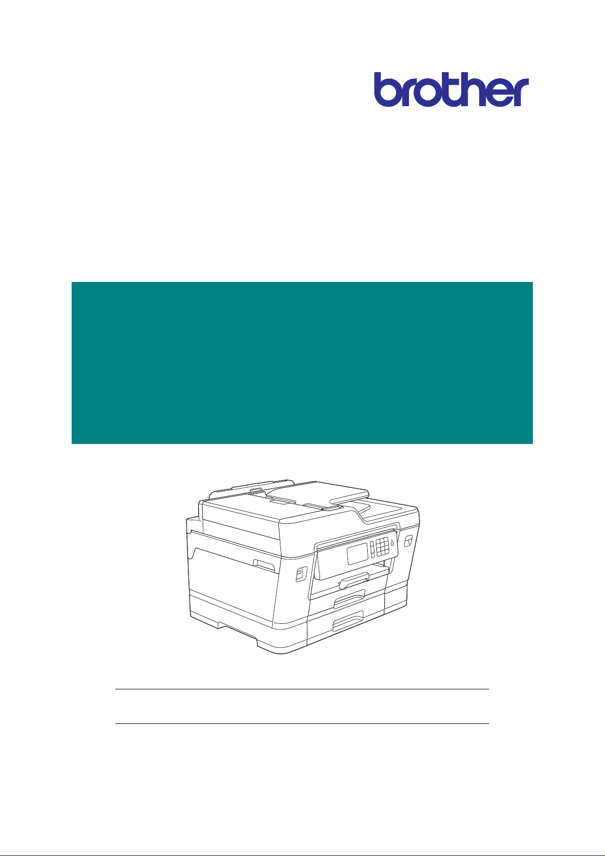
Brother Inkjet MFC
SERVICE MANUAL
MODELS:
HL-J6000DW/J6100DW/T4000DW
MFC-J3530DW/J3930DW/J6530DW
MFC-J6535DW/J6545DW/J6730DW
MFC-J6930DW/J6935DW/J6945DW
MFC-J6947DW/T4500DW
July 2016
SM-FAX172
8CH1* (4)
Read this manual thoroughly before maintenance work.
Keep this manual in a convenient place for quick and easy reference at all times.
Confidential

Trademarks
Microsoft, Windows, Windows Vista and Windows Server are either regis ter e d trad em a rks or
trademarks of Microsoft Corporation in the United States and/or other countries.
Macintosh and OS X are trademarks of Apple Inc., registered in the United States and other countries.
Wi-Fi is a registered trademark of Wi-Fi Alliance.
WPA and WPA2 are trademarks of Wi-Fi Alliance.
Each company whose software title is mentioned in this manual has a Software License Agreement
specific to its proprietary programs.
Any trade names and product names of companies appearing on Brother products, related
documents and any other materials are all trademarks or registered trademarks of those
respective companies.
Confidential
Preface
This Service Manual is intended for use by service personnel and details the specifications,
construction, and maintenance for the Brother machines noted on the front cover. It includes
information required for troubleshooting and ser vice--disassemb ly, reassemb ly, and lubrication-- so that
service personnel will be able to understand equipment function, repair the equipment in a timely
manner and order spare parts as necessary.
To perform appropriate maintenance so that the mach ine is always in the best possible condition for the
customer, service personnel must adequately understand and apply this manual.
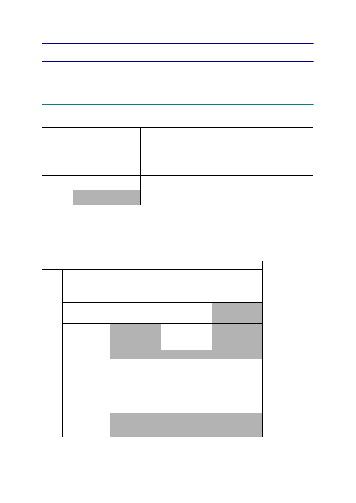
The table below shows the functional comparison between the models covered by this manual.
HL-
J6000DW
Scan --- --- --- Simplex Duplex Simplex Simplex
LCD 2.7 inch 2.7 inch 2.7 inch 2.7 inch 3.7 inch 2.7 inch 3.7 inch
Manual Feed
Slot
MP Tray √√√--- √ --- √
Lower Tray √√--- --- √ --- ---
3rd Tray --- √ --- --- --- --- ---
NFC √√--- --- √ --- ---
Document
Size Sensor
Paper
Remaining
Sensor
Ink Cartridge Simple Simple --- Regular Regular Regular Regular
Ink Tank --- --- √ --- --- --- ---
--- --- --- √ --- √ ---
--- --- --- --- --- --- √
√√--- --- --- --- ---
MFC-
J6545DW
HL-
J6100DW
MFC-
J6730DW
HL-
T4000DW
MFC-
J6930DW
MFC-
J3530DW
MFC-
J6935DW
MFC-
J3930DW
MFC-
J6945DW
MFC-
J6530DW
MFC-
J6947DW
MFC-
J6535DW
MFC-
T4500DW
Scan Simplex Simplex Duplex Duplex Duplex Duplex Simplex
LCD 3.7 inch 2.7 inch 3.7 inch 3.7 inch 3.7 inch 3.7 inch 2.7 inch
Manual Feed
Slot
MP Tray √ --- √√√√√
Lower Tray --- √√√√√---
3rd Tray --- --- --- --- --- √ ---
NFC --- --- √√√√---
Document
Size Sensor
Paper
Remaining
Sensor
Ink Cartridge Simple Regular Regular Regular Simple Simple --Ink Tank --- --- --- --- --- --- √
--- √ --- --- --- --- ---
√ --- --- √√√---
--- --- --- √√√---
Confidential

TABLE OF CONTENTS
SAFETY INFORMATION......................................................................................................... i
CHAPTER 1 SPECIFICATIONS.........................................................................................1-1
1 GENERAL......................................................................................................................1-1
1.1 General..................................................................................................................1-1
1.2 Media Specification ...............................................................................................1-1
1.3 Paper Handling......................................................................................................1-7
1.4 LCD Panel.............................................................................................................1-8
1.5 Memory..................................................................................................................1-8
1.6 Interface.................................................................................................................1-9
1.7 Others....................................................................................................................1-9
2 FAX...............................................................................................................................1-11
3 PRINTER......................................................................................................................1-11
4 COPY............................................................................................................................1-12
5 SCANNER....................................................................................................................1-12
6 SOFTWARE .................................................................................................................1-13
7 NETWORK ...................................................................................................................1-13
7.1 Network ...............................................................................................................1-13
7.2 Wired...................................................................................................................1-13
7.3 Wireless...............................................................................................................1-13
8 SUPPLIES/OPTIONS...................................................................................................1-14
9 SERVICE INFORMATION............................................................................................1-14
10 PAPER .........................................................................................................................1-15
10.1 Paper...................................................................................................................1-15
10.2 Unprintable Area..................................................................................................1-18
CHAPTER 2 TROUBLESHOOTING...................................................................................2-1
1 INTRODUCTION ............................................................................................................2-1
1.1 Precautions............................................................................................................2-1
1.2 Initial Check...........................................................................................................2-1
2 OVERVIEW ....................................................................................................................2-3
2.1 Cross-section Drawings.........................................................................................2-3
2.1.1 Document scanning ......................................................................................2-3
2.1.2 Printer part ....................................................................................................2-4
Confidential

2.2 Document Feeding Path/Recording Paper Feeding Path .....................................2-5
2.2.1 Document Feeding Path ...............................................................................2-5
2.2.2 Recording Paper Feeding Path.....................................................................2-5
2.3 Parts Names and Functions..................................................................................2-6
2.4 Block Diagram.......................................................................................................2-8
2.5 Components..........................................................................................................2-9
3 ERROR INDICATION...................................................................................................2-10
3.1 Error Code...........................................................................................................2-10
3.2 Error Messages ..................................................................................................2-17
3.3 Communications Error ........................................................................................2-21
4 TROUBLESHOOTING .................................................................................................2-25
4.1 Error Cause and Solutions ..................................................................................2-25
4.2 Recording Paper Feeding Problems...................................................................2-57
4.2.1 Paper is not fed from paper tray..................................................................2-57
4.2.2 Paper is not fed from manual feed slot .......................................................2-59
4.2.3 Paper is not fed from MP tray .....................................................................2-59
4.2.4 Two or more sheets of paper are fed from the paper tray...........................2-60
4.2.5 Two or more sheets of paper are fed from the MP tray. .............................2-60
4.2.6 Paper feeding at an angle...........................................................................2-61
4.2.7 Recording paper jam...................................................................................2-61
4.2.8 Prints only single side of the paper when duplex-printing...........................2-65
4.2.9 “No Paper Fed” is displayed........................................................................2-65
4.3 Print-image Problems..........................................................................................2-66
4.3.1 Defective images.........................................................................................2-66
4.3.2 Print-image problems..................................................................................2-67
4.4 Software-related Problems..................................................................................2-77
4.4.1 Cannot print data.........................................................................................2-77
4.5 Network Problems...............................................................................................2-77
4.5.1 Cannot make a print through network connection.......................................2-77
4.6 Control Panel Problems.......................................................................................2-78
4.6.1 No display on LCD/Incorrect display on LCD..............................................2-78
4.6.2 No display on LED ......................................................................................2-78
4.6.3 The control panel does not work.................................................................2-78
4.6.4 Touch panel inoperative..............................................................................2-79
4.7 Document Feeding Problems..............................................................................2-80
4.7.1 Document can not be fed............................................................................2-80
4.7.2 Document double feeding...........................................................................2-80
4.7.3 Document jam.............................................................................................2-81
Confidential

4.7.4 Wrinkles on documents...............................................................................2-83
4.7.5 Document size not correctly detected.........................................................2-83
4.8 Scanned-image Problems...................................................................................2-84
4.8.1 Defective images.........................................................................................2-84
4.8.2 Troubleshooting from image defect.............................................................2-84
4.9 Fax Problems ......................................................................................................2-89
4.9.1 No faxes can be sent ..................................................................................2-89
4.9.2 No faxes can be received............................................................................2-89
4.9.3 A communications error occurs...................................................................2-89
4.10 Other Problems ...................................................................................................2-90
4.10.1 The machine cannot be powered ON .........................................................2-90
4.10.2 USB flash memory does not function..........................................................2-90
4.10.3 Data of USB flash memory does not read...................................................2-90
4.10.4 Internal memory errors................................................................................2-91
4.10.5 Security Function Lock related problems....................................................2-91
4.10.6 Ink cartridge related problems.....................................................................2-91
4.10.7 Noise comes from machine.........................................................................2-92
4.10.8 “Unusable Device” is displayed...................................................................2-92
CHAPTER 3 DISASSEMBLY AND ASSEMBLY ...............................................................3-1
1 PRECAUTIONS BEFORE PROCEEDING ....................................................................3-1
2 PACKING .......................................................................................................................3-2
3 SCREW CATALOGUE...................................................................................................3-3
4 SCREW TORQUE LIST .................................................................................................3-4
5 LUBRICATION...............................................................................................................3-7
6 OVERVIEW OF GEARS...............................................................................................3-16
7 ROUTING OF HARNESSES AND INK SUPPLY TUBES ...........................................3-17
8 DISASSEMBLY FLOW ................................................................................................3-28
9 DISASSEMBLY PROCEDURE....................................................................................3-30
9.1 Preparation..........................................................................................................3-30
9.2 Head Joint Rubber/Head/carriage Unit/CR Timing Belt/< India model only >
Edge Cover Dust Foam.......................................................................................3-34
9.3 MP Side Cover L .................................................................................................3-45
9.4 MP Side Cover R .................................................................................................3-46
9.5 MP Tray ASSY/MP Paper Detection Sensor PCB/< India model only >
MP Dust Foam.....................................................................................................3-47
9.6 Jam Clear Cover..................................................................................................3-50
Confidential

9.7 Top Cover ASSY (Printer model) ........................................................................3-51
9.8 Document Scanner Side Cover L (MFC model)..................................................3-54
9.9 Document Scanner Side Cover R/< India model only > Document Scanner
Dust Foam...........................................................................................................3-59
9.10 ADF Unit/Document Scanner Unit.......................................................................3-60
9.11 ADF Front Cover .................................................................................................3-61
9.12 ADF Side Cover...................................................................................................3-61
9.13 ADF Rear Cover..................................................................................................3-62
9.14 ADF Cover...........................................................................................................3-62
9.15 Document Separation Roller ASSY.....................................................................3-63
9.16 ADF Separation Pad Holder ASSY.....................................................................3-64
9.17 ADF Document Support ......................................................................................3-65
9.18 ADF Hinge...........................................................................................................3-67
9.19 ADF Document Detection Sensor/ADF Document Width Sensor PCB...............3-69
9.20 Document Scanning Position Sensor PCB..........................................................3-70
9.21 Second Side CIS Flat Cable/Second Side CIS Unit............................................3-71
9.22 First Side CIS Unit/First Side CIS Flat Cable......................................................3-75
9.23 Document Cover Sensor.....................................................................................3-79
9.24 Front Cover L.......................................................................................................3-79
9.25 Ink Cartridge Cover .............................................................................................3-80
9.26 Upper Cover/< India model only > Upper Cover Dust Foam...............................3-80
9.27 Control Panel ASSY............................................................................................3-83
9.28 Panel Flat Cable..................................................................................................3-86
9.29 NFC PCB.............................................................................................................3-88
9.30 Panel PCB...........................................................................................................3-88
9.31 LCD PCB.............................................................................................................3-89
9.32 LCD .....................................................................................................................3-90
9.33 Touch Panel ........................................................................................................3-93
9.34 Wireless LAN PCB ..............................................................................................3-95
9.35 Main PCB ............................................................................................................3-97
9.36 Modem PCB........................................................................................................3-98
9.37 Maintenance Unit.................................................................................................3-99
9.38 Ink Absorber Felt (For Maintenance Unit) .........................................................3-107
9.39 Carriage PCB ASSY..........................................................................................3-108
9.40 Tank Case ASSY (Ink tank model only)............................................................3-110
9.41 Ink Refill ASSY..................................................................................................3-111
9.42 Ink Absorber Felt (For Ink Refill ASSY).............................................................3-112
9.43 Ink Cartridge Cover Sensor...............................................................................3-114
9.44 Ink Absorber Box...............................................................................................3-115
9.45 Switchback Sensor PCB....................................................................................3-116
Confidential

9.46 CR Encoder Strip...............................................................................................3-117
9.47 Carriage Motor...................................................................................................3-118
9.48 Flushing Base....................................................................................................3-121
9.49 LT Frame ASSY (T2 Paper Pull-in Roller L/R)..................................................3-122
9.50 T2 Bank ASSY...................................................................................................3-126
9.51 Power Supply PCB ASSY .................................................................................3-127
9.52 Switchback Roller..............................................................................................3-129
9.53 PF Encoder Disk................................................................................................3-130
9.54 PF Encoder Sensor PCB...................................................................................3-131
9.55 Paper Feed Motor..............................................................................................3-133
9.56 Paper Feed Roller .............................................................................................3-135
9.57 Platen/Paper Ejection Roller..............................................................................3-136
9.58 Registration Sensor PCB...................................................................................3-139
9.59 Flushing Box......................................................................................................3-142
9.60 Paper Feed Arm Frame ASSY (T1 Paper Pull-in Roller L/R)............................3-142
9.61 T1 Bank ASSY...................................................................................................3-144
9.62 T1 Base Pad / T2 Base Pad / T3 Base Pad......................................................3-146
9.63 3rd Tray Relay PCB...........................................................................................3-147
9.64 3rd Tray Paper Pull-in Sensor PCB...................................................................3-148
9.65 Intermediate Roller............................................................................................3-149
9.66 3rd Tray Paper Feed Motor...............................................................................3-149
9.67 T3 Bank ASSY...................................................................................................3-153
9.68 T3 Paper Pull-in Roller L/R................................................................................3-155
CHAPTER 4 ADJUSTMENTS AND UPDATING OF SETTINGS,
REQUIRED AFTER PARTS REPLACEMENT..............................................4-1
1 IF YOU REPLACE THE MAIN PCB...............................................................................4-1
1.1 Customize destinations (Maintenance mode 74)..................................................4-3
1.2 < Except for Printer model > Set the CIS type (Maintenance mode 59)................4-3
1.3 Install the firmware (Maintenance mode 28) .........................................................4-3
1.4 Initialize the EEPROM parameters (Maintenance mode 01).................................4-5
1.5 Restore the head calibration data (Maintenance mode 68)...................................4-5
1.6 Set the serial number (Maintenance mode 80).....................................................4-5
1.7 Updating of head property information (Maintenance mode 68)...........................4-6
1.8 Restore machine information (Maintenance mode 46)..........................................4-6
1.9 Adjust the touch panel (Maintenance mode 78)....................................................4-7
1.10 < Except for Printer model > Acquire white/black level data
(Maintenance mode 55).........................................................................................4-7
1.11 Adjustment of software correction for inclination/corrugation/ruled lines
(Maintenance mode 65 / User menu)....................................................................4-7
Confidential

1.12 Updating of paper feeding correction values (Maintenance mode 58 /
User menu)............................................................................................................4-7
1.13 Adjustment of margins in borderless printing (Maintenance mode 66) .................4-7
1.14 Reset purge and flushing counts...........................................................................4-7
1.15 < Paper remaining sensor model only > Disable inter-machine variation calibration
for paper remaining sensor (Maintenance mode 88 <Selector 1 on AMS04>).....4-8
1.16 Write head calibration data (Maintenance mode 02).............................................4-8
1.17 Check scanning and printing.................................................................................4-8
2 IF YOU REPLACE THE HEAD/CARRIAGE UNIT.........................................................4-9
2.1 Update the head property information (Maintenance mode 68)..........................4-10
2.2 Perform ink supply purge (Maintenance mode 76)..............................................4-11
2.3 Check head nozzles (Maintenance mode 09).....................................................4-11
2.4 Adjust head inclination.........................................................................................4-11
2.5 Adjustment of software correction for inclination/corrugation/ruled lines
(Maintenance mode 65 / User menu)..................................................................4-12
2.6 Updating of paper feeding correction values (Maintenance mode 58 /
User menu)..........................................................................................................4-13
2.7 Adjustment of margins in borderless printing (Maintenance mode 66) ...............4-13
2.8 Write head calibration data (Maintenance mode 02)...........................................4-13
2.9 Check printing......................................................................................................4-13
2.10 Obtain machine information at the user site (Instruction to the end user)...........4-13
3 IF YOU REPLACE THE DOCUMENT SCANNER UNIT, ADF UNIT OR CIS UNIT....4-14
3.1 Set the CIS type (Maintenance mode 59) (Not required after replacement of the
ADF unit on simplex scanning models)...............................................................4-14
3.2 Acquire white/black level data (Maintenance mode 55) (Not required after
replacement of the ADF unit on simplex scanning models)................................4-14
3.3 Check scanning...................................................................................................4-14
4 IF YOU REPLACE THE CONTROL PANEL ASSY.....................................................4-15
4.1 Adjust the touch panel (Maintenance mode 78)..................................................4-15
4.2 Check LCD operation (Maintenance mode 12)...................................................4-15
4.3 Check the operation of the control panel keys (Maintenance mode 13).............4-15
5 IF YOU REPLACE THE INK ABSORBER BOX OR FLUSHING BOX .......................4-15
5.1 Reset purge or flushing counts............................................................................4-15
6 IF YOU REPLACE THE PAPER FEEDING RELATED PARTS AND
MAINTENANCE UNIT..................................................................................................4-16
6.1 Check head nozzles (Maintenance mode 09).....................................................4-17
6.2 Adjustment of software correction for inclination/corrugation/ruled lines
(Maintenance mode 65 / User menu)..................................................................4-17
6.3 Updating of paper feeding correction values (Maintenance mode 58 /
User menu)..........................................................................................................4-17
Confidential

6.4 Adjustment of margins in borderless printing (Maintenance mode 66) ...............4-17
6.5 < Only when replacing the Paper feed arm frame ASSY or LT frame ASSY of the
paper remaining sensor model > Disable inter-machine variation calibration for paper
remaining sensor(Maintenance mode 88 <Selector 1 on AMS04>)....................4-17
6.6 Check printing......................................................................................................4-17
CHAPTER 5 SERVICE FUNCTIONS .................................................................................5-1
1 MAINTENANCE MODE .................................................................................................5-1
1.1 Entry to the Maintenance Mode.............................................................................5-1
1.1.1 How to Enter the Maintenance Mode for Service Personnel........................5-1
1.1.2 How to Enter the End User-accessible Maintenance Mode..........................5-3
1.2 List of Maintenance-mode Functions.....................................................................5-4
1.3 Detailed Description of Maintenance-mode Functions..........................................5-5
1.3.1 EEPROM Parameter Initialization (Maintenance mode 01, 91)....................5-5
1.3.2 Creating of Head Calibration Data and Writing it into Flash ROM
(Maintenance mode 02)................................................................................5-6
1.3.3 ADF Performance Test (Maintenance mode 08)........................................5-11
1.3.4 Printout of Test Pattern (Maintenance mode 09)........................................5-12
1.3.5 Worker Switch Setting and Printout (Maintenance modes 10 and 11)........5-13
1.3.6 Operational Check of LCD (Maintenance mode 12)...................................5-15
1.3.7 Operational Check of Keys on Control Panel (Maintenance mode 13).......5-17
1.3.8 Updating of Firmware Using a USB flash memory
(Maintenance mode 28)..............................................................................5-18
1.3.9 Sensor Operational Check (Maintenance mode 32)...................................5-19
1.3.10 Printout of Dial Log (Maintenance mode 37)...............................................5-21
1.3.11 PCL/PS function setting (Maintenance mode 45).......................................5-22
1.3.12 Backup of Machine Information (Maintenance mode 46)............................5-23
1.3.13 Transfer of Received FAX Data and/or Equipment's Log
(Maintenance mode 53)..............................................................................5-25
1.3.14 Fine Adjustment of Scanning Position (Maintenance mode 54) .................5-27
1.3.15 Acquisition of White/Black Level Data (Maintenance mode 55)..................5-28
1.3.16 Periodic Purge Time Setting (Ink tank model/Simple Ink cartridge model
only)(Maintenance mode 56) ......................................................................5-28
1.3.17 Cartridge IC Communication Check (Maintenance mode 57).....................5-29
1.3.18 Updating of Paper Feeding Correction Values (Maintenance mode 58).....5-30
1.3.19 Checking of CIS Travel and Specifying of CIS Type
(Maintenance mode 59)..............................................................................5-34
1.3.20 Printout of PRN/JPEG Files in USB Flash Memory
(Maintenance mode 61)..............................................................................5-35
1.3.21 Move of the Head/Carriage Unit to the Adjustment Position
(Maintenance mode 63)..............................................................................5-36
1.3.22 Adjustment of Software Correction for Inclination/Corrugation/Ruled Lines
(Maintenance mode 65)..............................................................................5-37
Confidential

1.3.23 Adjustment of Margins in Borderless Printing (Maintenance mode 66) ......5-39
1.3.24 Updating of Head Property Information and Backup/Restoration of Head
Calibration Data (Maintenance mode 68) ...................................................5-41
1.3.25 Traveling Speed Check of Head/Carriage Unit (Maintenance mode 69)....5-43
1.3.26 Customizing Destinations (Maintenance mode 74).....................................5-43
1.3.27 Move of the Head/Carriage Unit to the Center
(Maintenance mode 75)..............................................................................5-46
1.3.28 Purge Operation (Maintenance mode 76)...................................................5-47
1.3.29 Print of the Maintenance Information (Maintenance mode 77)...................5-51
1.3.30 Adjustment of Touch Panel (Maintenance mode 78)..................................5-58
1.3.31 Display of the Equipment's Log (Maintenance mode 80)............................5-59
1.3.32 Equipment Error Code Indication (Maintenance mode 82).........................5-72
1.3.33 Output of Transmission Log to the Telephone Line
(Maintenance mode 87)..............................................................................5-72
1.3.34 Assurance Mode Switch Setting (Maintenance mode 88) ..........................5-73
1.3.35 Printout of Block Pattern (Ink tank model / Simple Ink cartridge model only)
(Maintenance mode 89)..............................................................................5-82
2 OTHER SERVICE FUNCTIONS ..................................................................................5-83
2.1 Displaying the Firmware Version.........................................................................5-83
2.2 Moving the Head/Carriage Unit...........................................................................5-83
2.3 Retrieving the Equipment Log Information..........................................................5-84
2.4 Special purge (SPP) < Ink tank model only >......................................................5-85
CHAPTER 6 CIRCUIT DIAGRAMS AND WIRING DIAGRAMS........................................6-1
CHAPTER 7 PERIODICAL MAINTENANCE .....................................................................7-1
1 PERIODICAL REPLACEMENT PARTS........................................................................7-1
APPENDIX 1 SERIAL NUMBERING SYSTEM..........................................................App. 1-1
APPENDIX 2 DELETION OF USER SETTING INFORMATION................................App. 2-1
APPENDIX 3 INSTALLING THE MAINTENANCE PRINTER DRIVER .....................App. 3-1
Confidential
SAFETY INFORMATION
WARNING
CAUTION
WARNING indicates a potentially hazardous situation which, if not avoided, could result in
death or serious injuries.
CAUTION indicates a potentially hazardous situation which, if not avoided, may result in
minor or moderate injuries.
IMPORTANT
IMPORTANT indicates a potentially hazardous situation which, if not avoided, may result in
damage to property or loss of machine functionality.
NOTE
NOTE specifies the operating environment, conditions for installation, or special conditions
of use.
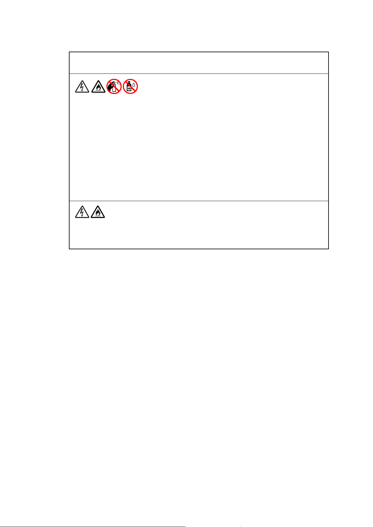
Prohibition icons indicate actions that must not be performed.
This icon indicates that flammable sprays must not be used.
This icon indicates that organic solvents such as alcohol and liquids must not be
used.
Electrical Hazard icons alert you to possible electrical shocks.
Fire Hazard icons alert you to the possibility of fire.
Italics
Italicized typeface emphasizes an important point or refers you to a related topic.
NOTE
The illustrations in this guide show MFC-J6930DW.
i
Confidential
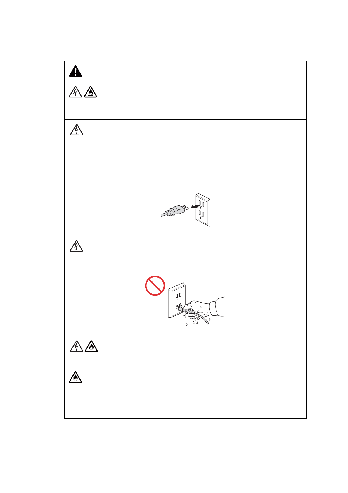
To use the machine safely
WARNING
ELECTRICAL HAZARDS
Failure to follow the warnings in this section may create the risk of an electrical shock. In
addition, you could create an electrical short, which may create the risk of a fire.
There are high-voltage electrodes inside the machine. Before you access the inside of the
machine, including for routine maintenance such as cleaning, make sure you have
unplugged the power cord from the AC power outlet, as well as any telephone/RJ-11 or
Ethernet/RJ-45 cables from the machine.
DO NOT push objects of any kind into this machine through slots or openings in the cabinet, as they may touch dangerous voltage points or short out parts.
DO NOT handle the plug with wet hands.
Always make sure the plug is fully inserted.
Unplug the power plug regularly to clean it. Use a dry cloth to clean the root of the plug
blades and between the blades. If the power plug is plugged into the outlet over a lon g
period, dust accumulates around the plug blades, which may cause a short circuit, resulting
in a fire.
ii
Confidential
DO NOT take apart or attempt to convert the machine. This may create a risk of fire or
electrical shock. Such conduct may also be punished by the law.
If the machine has been dropped or the casing has been damaged, there may be the
possibility of an electrical shock. Unplug the machine from the AC power outlet.
DO NOT drop any metallic hardware or any type of liquid on the power plug of the machine.
It may cause an electrical shock or a fire.
If water, other liquids, or metal objects get inside the machine, immediately unplug the
machine from the AC power outlet.
This machine should be connected to an AC power source within the range indicated on the
rating label. DO NOT connect it to a DC power source or inverter. If you are not sure what
kind of power source you have, contact a qualified electrician.
Power Cord Safety:
- DO NOT pull on the middle of the AC power cord; pulling on the middle may cause the
cord to separate from the plug. Doing this might cause an electrical shock.
- DO NOT allow anything to rest on the power cord.
- DO NOT place this machine where people can walk on the cord.
- DO NOT place this machine in a position where the cord is stretched or strained, as it may
become worn or frayed.
- DO NOT use the machine or handle the cord if the cord has become worn or frayed. If
unplugging your machine, DO NOT touch the damaged/frayed part.
DO NOT use this machine during an thunderstorm.
Use caution when installing or modifying telephone lines. Never touch telephone wires or
terminals that are not insulated unless the telephone line has been unplugged at the wall
jack. Never install telephone wiring during a lightning storm. Never install a telephone wall
jack in a wet location.
iii
Confidential
FIRE HAZARDS
Failure to follow the warnings in this section may create the risk of a fire.
DO NOT use flammable substances, any type of spray, or an organic solvent/liquid
containing alcohol or ammonia to clean the inside or out side of the machine. Doing so could
cause a fire or electrical shock. Instead, use only a dry, lint-free cloth.
DO NOT use the machine near any medical electrical equipment. The radio wave emitted
from the machine may affect medical electrical equipment and cause a malfunction, which
may result in accident or injury.
For users with pacemakers
This machine generates a weak magnetic field. If you feel anything wrong with the opera-
tion of your pacemakers when near the machine, move away from the machine and consult
a doctor immediately.
If the machine becomes unusually hot, releases smoke, generates any strong smells, or if
you accidentally spill any liquid on it, immediately unplug the machine from the AC power
outlet.
iv
Confidential
CAUTION
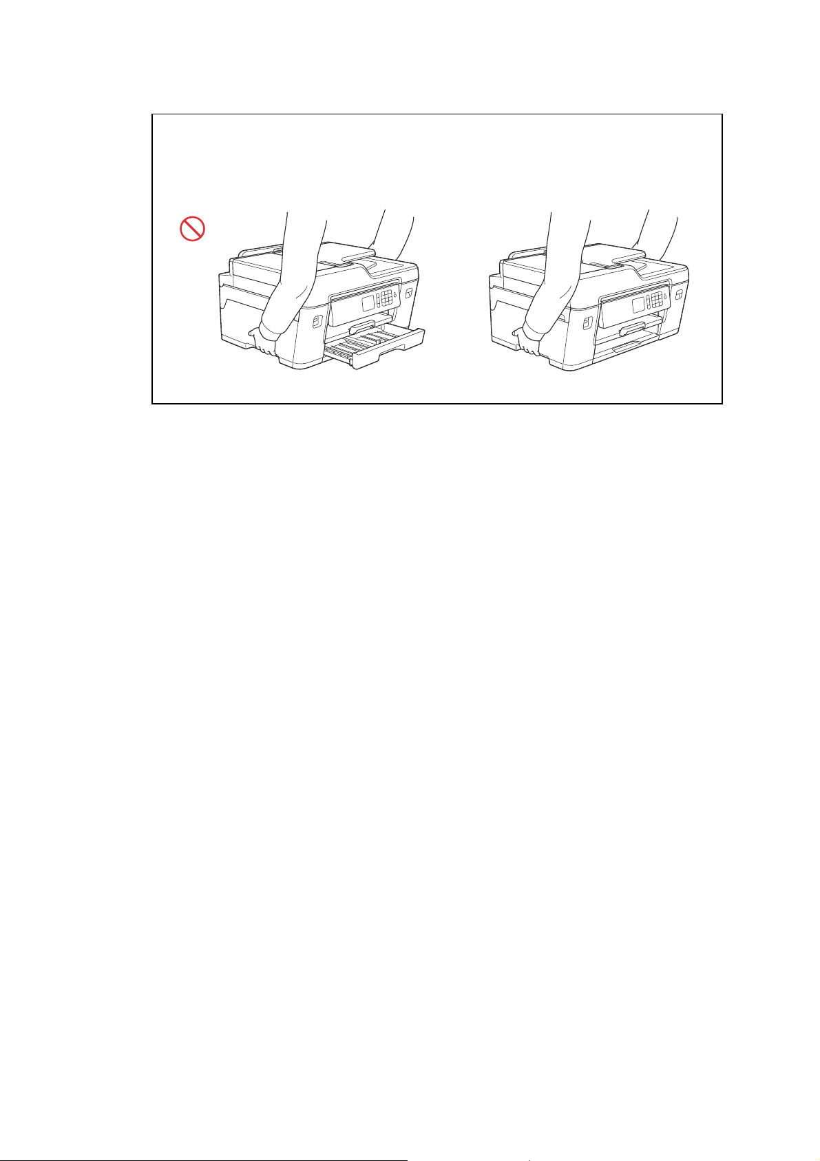
Wait until pages have exited the machine before picking them up. Failure to do this may
cause injury to your fingers by trapping them in a roller.
DO NOT put your hand or any foreign objects into the ink insertion slot. Doing this may
cause injury.
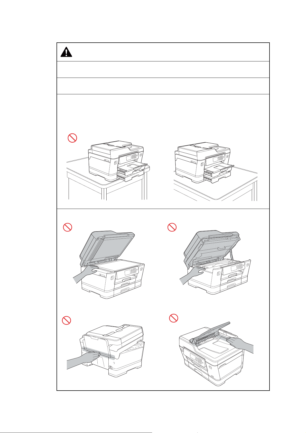
If the trays have been expanded to hold large p aper such as Ledger, A3, Legal or Folio size
paper, place the machine on a flat surface that can support both the machine and the trays.
When the trays are expanded, they will protrude from the machine. Therefore, if someone
hits the trays, the machine could fall and cause injury.
To prevent injuries, be careful not to put your fingers in the areas shown in the illustrations.
v
Confidential
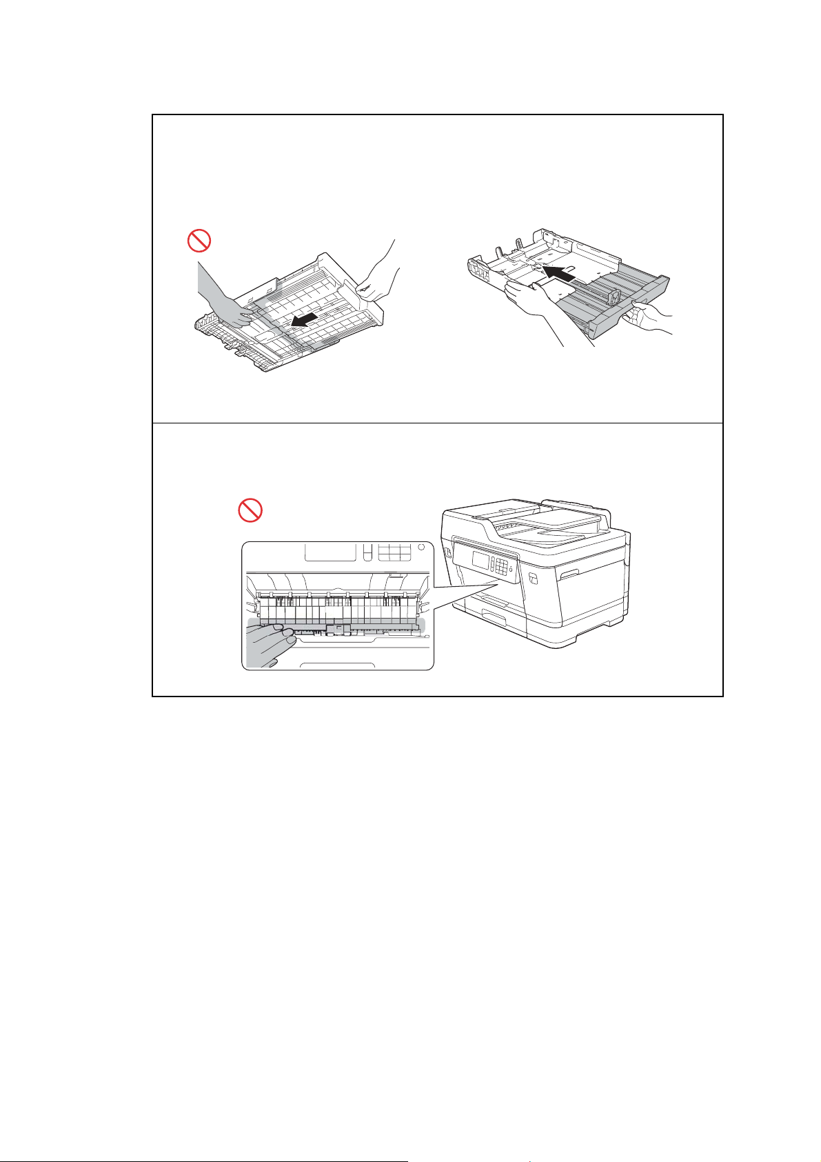
When changing the tray size from the Ledger , A3 , Legal or Folio size to the original size, be
careful not to pinch your fingers in the gaps or slots in the bottom of the tra y. It may cause
injury to you.
Be careful not to put your fingers in the areas shown in the illustrations. It may cause injury
to you.
vi
Confidential
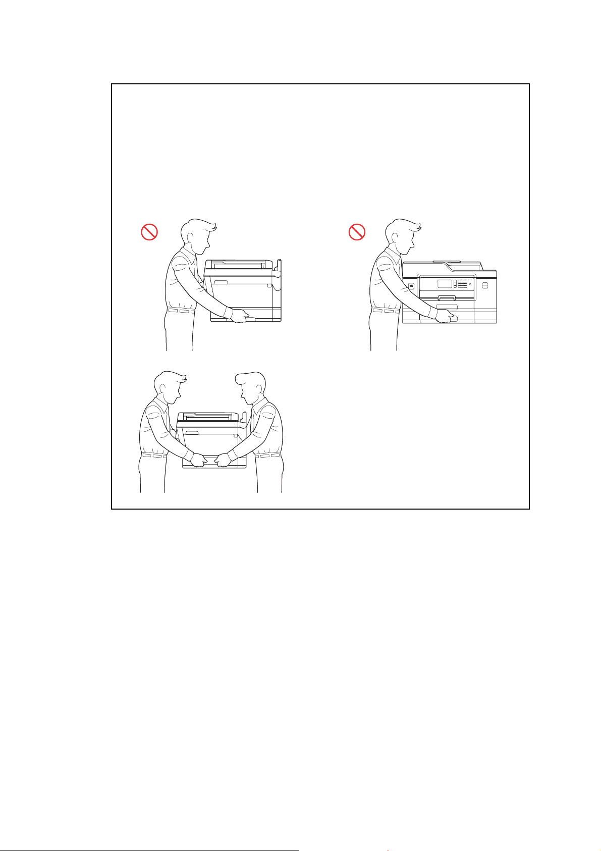
To prevent possible injuries, at least two people should lift the machine. One person should
hold the front of the machine, and one person should hold the back, as shown in the
illustration below.
Carry the machine by sliding your hands into the handhold indentations located on each
side of the machine. Be careful not to trap your fingers when you put the machine down.
DO NOT carry the machine by holding the lower tray when it is installed. The lower tray
could fall and cause injury to you.
vii
Confidential
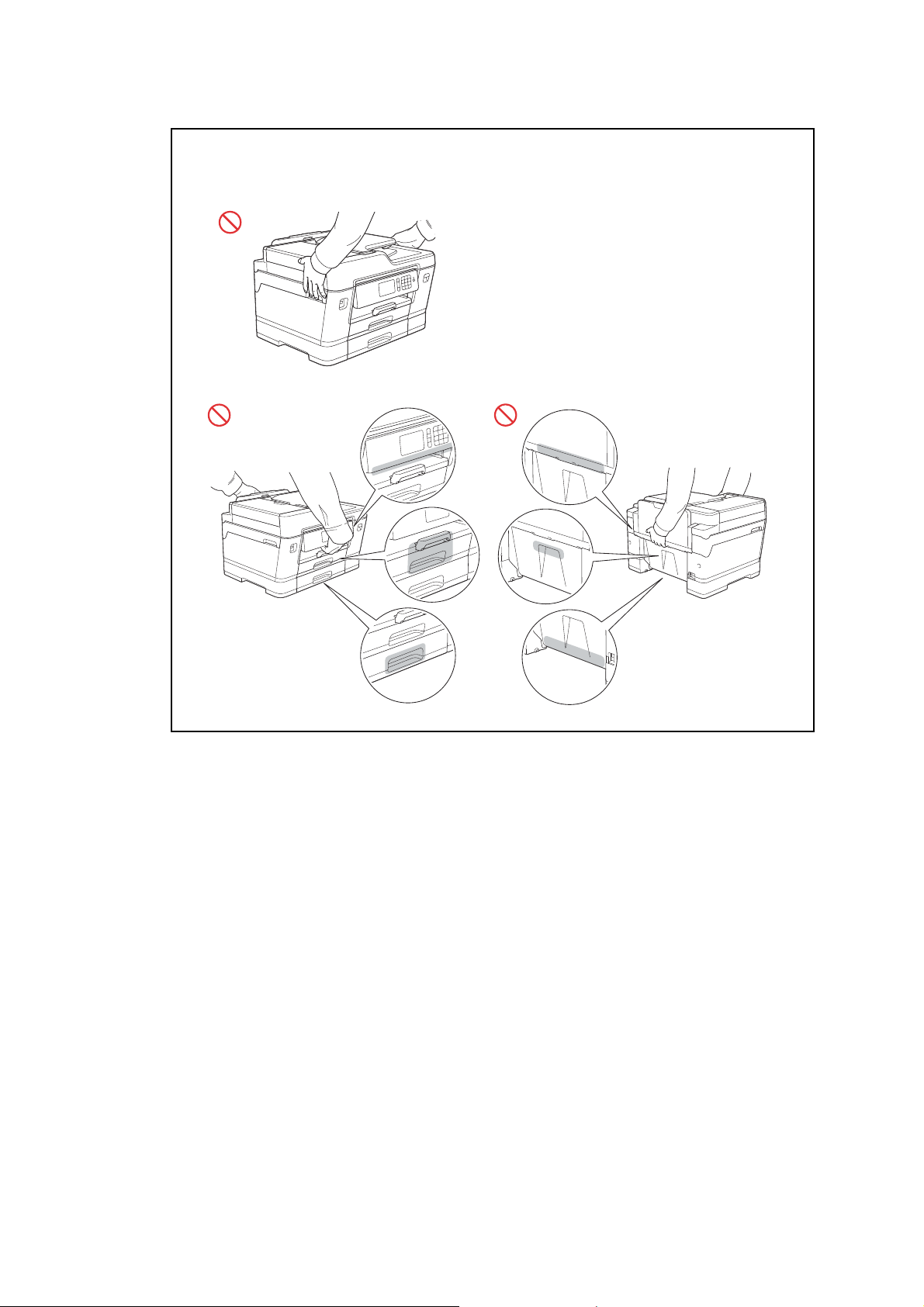
DO NOT carry the machine by holding the areas shown in the illustrations. Doing this may
cause the machine to slip out of your hands and may result in injury.
viii
Confidential
When carrying the machine, remove the trays if they have been expanded to ho ld large
paper such as Ledger, A3, Legal or Folio size paper. The weight of the pape r could cause
the trays to fall and cause injury to you.
If the ink contacts your skin or gets into your eye or mouth, please follow these steps
immediately:
- If your skin comes into contact with the ink, wash your skin with water and soap
immediately.
- If the ink gets into your eye, rinse it with water immediately. If left as is, it may cause
redness or mild inflammation of the eye. In case of any abnormality, consult with your
doctor.
- If the ink gets into your mouth, spit it out, rinse your mouth, and consult your doctor
immediately.
- Be careful not to get the ink in your eye when replacing the ink cartridge or refilling ink.
- Keep the ink cartridge or ink bottles out of the reach of children.
- DO NOT shake the ink cartridge. The ink may leak out if the cartridge is shaken or twirled.
- DO NOT take apart the ink cartridge. The cartridge can not be used if it is t a ken apart. The
ink may get in your eye or make contact with your skin if you t ake apart the cartridge.
When multiple devices, including this machine, are connected to a compute r usin g USB
cables, you may feel an electrical charge when you touch meta l part s of the machine. Avoi d
touching them.
IMPORTANT
- Disruption of power can wipe out information in the machine's memory.
- If the machine does not operate normally when the operating instructions are followed,
adjust only those controls that are covered by the operating instructions. Incorrect
adjustment of other controls may result in damage.
- DO NOT connect your machine to an AC power outlet controlled by wall switches,
automatic timers or to the same circuit as a large appliance, such as an air conditioner,
copier, shredder, or other eq uipment that requires a significant amount of electricity to
operate. Operating this machine in conjunction with the other machine(s) could create an
overvoltage, tripping your circuit breaker or blowing your fuse ; or migh t disr up t the po we r
supply . Disruption of the power supply may delete information from the machine’s memory
and repeated cycling of the power supply can damage the machine.
ix
Confidential

Precautions for Troubleshooting and/or Disassembly/Assembly
Be sure to observe the following warnings and precautions to prevent any secondary troubles
from happening by mishandling the machine during troubleshooting and/or disassembly/
assembly.
Precautions
Be sure to observe the following to prevent any secondary troubles from happening duri ng
troubleshooting and/or disassembly/assembly.
(1) Power cord must be removed from their outlet s befo re st arting any remo val of covers and
PCBs, adjustments and conductivity test using a tester.
(2) Be careful not to lose screws, washers, or other parts.
(3) Apply grease to the points specified in
(4) When using soldering irons and other heat-generating tools, take care not to damage the
plastic parts such as wires, PCBs, and covers.
(5) When disconnecting the connectors, hold the connector housings. Do not pull the lead wires.
(6) After disconnecting flat cables, check that each cable is not damaged at its end or
shortcircuited.
(7) When connecting flat cables, do not insert them at an angle. After insertion, check again
that the cables are not at an angle.
(8) When connecting or disconnecting harnesses, hold the connector bodies not the cables.
If the connector has a lock, always unlock it.
(9) After repairs, check not only the repaired portion but also that the harnesses are routed
properly. Also check that the other related portions function properly.
(10)Static electricity charged in your body may damage electronic parts.
Before handling the PCBs, touch a metal portion of the machine to discharge static
electricity charged in your body. When transporting PCBs, be sure to wrap them in
conductive sheets.
When replacing the PCBs, put on a grounding wrist band and perform the job on a
conductive mat.
Also take care not to touch the conductor sections on the flat cables.
(11) Once the head/carriage unit prints, it will start head locking operation after five seconds
from the end of printing. The head locking operation will take five to ten seconds. NEVER
unplug the power cord before the machine completes the head locking operation; doing
so will make the head/carriage unit unusable and require replacement with a new head/
carriage unit. When you receive the machine from the user or when you pack it for
sending it back to the user, check the head locking state.
(12)If ink gets on your skin or gets into your eyes or mouth, you need the following treatment.
- If ink gets on your skin, wash it off immediately with soap and water.
Chapter 3.
- If ink gets into your eyes, flush them immediately and thoroughly with water. If left
untreated, the eyes may become bloodshot or mildly inflamed. If you feel any discomfort,
consult a doctor immediately.
- If ink gets into your mouth, immediately spit it out and consult a doctor.
(13)Be sure to observe the warnings.
(14)After completion of reassembly, it is recommended that the dielectric voltage withstand
test and continuity test be conducted.
(15) After repairing the defective section, be sure to check again if the repaired section works
correctly.
x
Confidential
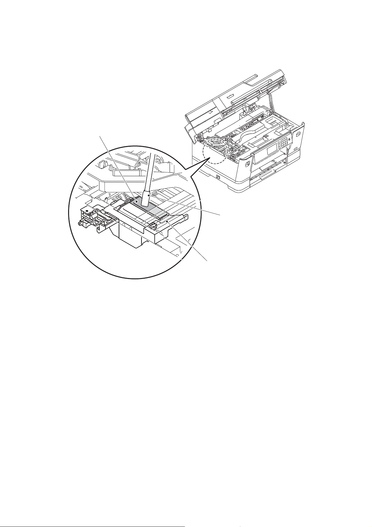
(16)Before packing the machine for sending it back to the user after repairs, be sure to clean
Cleaner stick
Flushing guide
Flushing base
the flushing guide with a cleaner stick as shown below to prevent ink splashing during
transportation.
xi
Confidential
CHAPTER 1 SPECIFICATIONS
This chapter lists the specifications of each model, which enables you to make a comparison
of different models.
1GENERAL
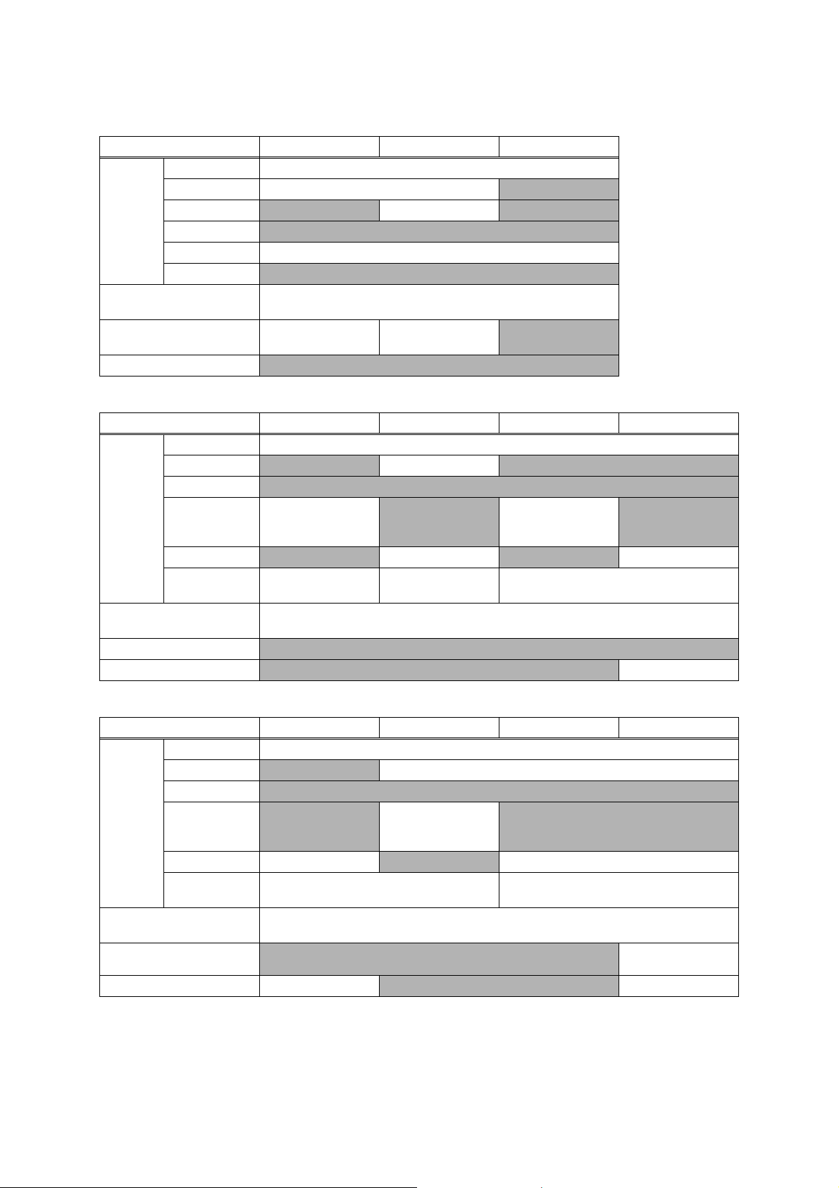
1.1 General
Model
Print Head
Minimum
Droplet Size
Scanning
Method
CPU Speed 576 MHz
Backup
Clock
HL-J6000DW/
J6100DW
BHS13plus
Head
BK/C/M/Y:
420/420/420/
420 nozzles
BK: 4 pl
CMY: 1.5 pl
HL-T4000DW
BHM17HT
Head
BK/C/M/Y:
420/420/420/
420 nozzles
BK: 3 pl
CMY: 1.5 pl
N/A CIS
MFC-J3530DW/J3930DW/J6530DW/J6535DW/J6545DW/
J6730DW/J6930DW/J6935DW/J6945DW/J6947DW
BHS13plus Head
BK/C/M/Y: 420/420/420/420 nozzles
Yes (Up to 1 hour)
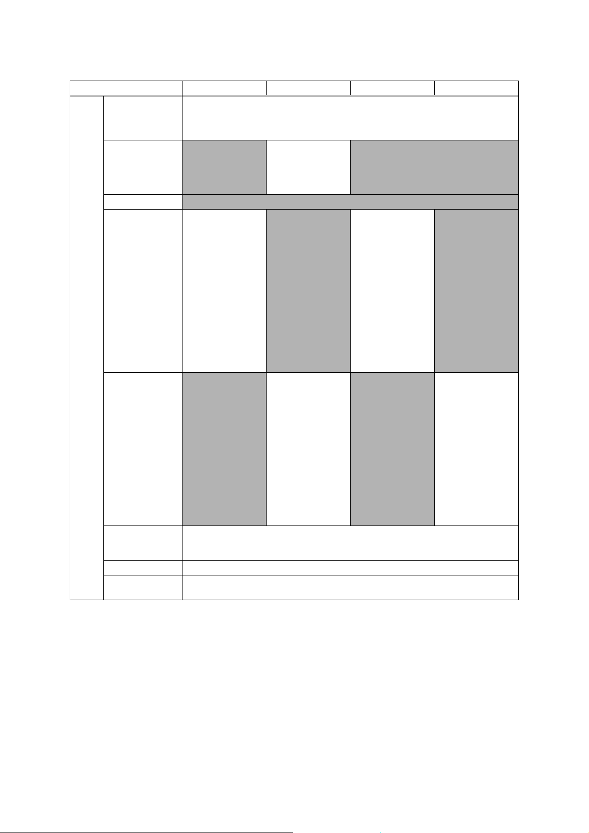
1.2 Media Specification
Model HL-J6000DW HL-J6100DW HL-T4000DW
*1
N/A
*1
, LGL, Folio, A4, LTR, EXE, A5,
N/A
Standard Tray
Lower Tray
3rd Tray
Media
Sizes
*1
*2
Manual Feed Slot
MP Tray
Duplex Print
ADF (width/length) N/A
Scanner Glass
(width/length)
Only for Taiwan/China
Only for China
<Landscape> A4, LTR, EXE, B5 (JIS)
<Portrait> A3, LGR, B4 (JIS)*1, LGL, Folio, A5, B6 (JIS)*1, A6, Photo
(102 x 152 mm/4 x 6"), Index card (127 x 203 mm/5 x 8"), Photo-L (89 x
127 mm/3.5 x 5"), Photo-2L (127 x 178 mm/5 x 7"), C5, Com-10, DL
Envelope, Monarch, Mexico Legal, India Legal, 16K (195 x 270 mm)
<Landscape> A4, LTR
<Portrait> A3, LGR, LGL, Folio, Mexico Legal,
India Legal
<Landscape> A4, LTR
N/A
<Landscape> A4, LTR, EXE, B5 (JIS)
<Portrait> A3, LGR, B4 (JIS)*1, LGL, Folio, A5, B6 (JIS)*1, A6, Photo
(102 x 152 mm/4 x 6"), Index card (127 x 203 mm/5 x 8"), Photo-L (89 x
127 mm/3.5 x 5"), Photo-2L (127 x 178 mm/5 x 7"), Com-10, DL
Envelope, Monarch, C5, Mexico Legal, India Legal, 16K (195 x 270
*2
mm)
<PC Print> A3, LGR, B4(JIS)
*1
B5(JIS)
, B6(JIS)*1, Mexico Legal, India Legal, 16K (195x270mm)
<Portrait> A3, LGR,
LGL, Folio, Mexico
Legal, India Legal
*1
BK: 4 pl
CMY: 1.5 pl
MFC-
T4500DW
BHM17HT
Head
BK/C/M/Y:
420/420/420/
420 nozzles
BK: 3 pl
CMY: 1.5 pl
*2
N/A
N/A
*2
1-1
Confidential
Media
Sizes
Model MFC-J3530DW MFC-J3930DW MFC-J6530DW MFC-J6535DW
*1
Standard Tray
<Landscape> A4, LTR, EXE, B5 (JIS)
<Portrait> A3, LGR, B4 (JIS)*1, LGL, Folio, A5, B6 (JIS)*1, A6, Photo (102 x 152 mm/4 x 6"),
Index card (127 x 203 mm/5 x 8"), Photo-L (89 x 127 mm/3.5 x 5"), Photo-2L (127 x 178 mm/5 x
7"), C5, Com-10, DL Envelope, Monarch, Mexico Legal, India Legal, 16K (195 x 270 mm)
<Landscape> A4, LTR
<Portrait> A3, LGR,
Lower Tray N/A
B4 (JIS)*1, LGL, Folio,
N/A
Mexico Legal, India
Legal
3rd Tray
Manual Feed Slot
MP Tray
Duplex Print
<Landscape> A4,
LTR, EXE, B5 (JIS)
<Portrait> A3, LGR,
*1
B4 (JIS)
, LGL, Folio,
A5, B6 (JIS)
*1
*1
, A6,
Photo (102 x 152 mm/
4 x 6"), Index card
(127 x 203 mm/5 x 8"),
Photo-L (89 x 127 mm/
N/A
3.5 x 5"), Photo-2L
(127 x 178 mm/5 x 7"),
C5, Com-10, DL
Envelope, Monarch,
Mexico Legal, India
Legal,16K (195 x 270
*2
mm)
<Landscape> A4,
LTR, EXE, B5 (JIS)
<Portrait> A3, LGR,
*1
B4 (JIS)
A5, B6 (JIS)
, LGL, Folio,
*1
Photo (102 x 152 mm/
4 x 6"), Index card
N/A
(127 x 203 mm/5 x 8"),
Photo-L (89 x 127 mm/
3.5 x 5"), Photo-2L
(127 x 178 mm/5 x 7"),
Com-10, DL Envelope,
Monarch, C5, Mexico
Legal, India Legal,
16K (195 x 270 mm)
*1
<PC Print> A3, LGR, B4 (JIS)
, LGL, Folio, A4, LTR, EXE, A5, B5 (JIS)*1, B6 (JIS)*1, Mexico
Legal, India Legal, 16K (195 x 270 mm)
, A6,
*2
N/A
<Landscape> A4,
LTR, EXE,
<Portrait> A3, LGR,
LGL, Folio, A5, A6,
Photo (102 x 152 mm/
4 x 6"), Index card
(127 x 203 mm/5 x 8"),
Photo-L (89 x 127 mm/
3.5 x 5"), Photo-2L
(127 x 178 mm/5 x 7"),
C5, Com-10, DL
Envelope, Monarch,
Mexico Legal, India
Legal
*1
N/A
*2
N/A
<Landscape> A4,
LTR, EXE
<Portrait> A3, LGR,
LGL, Folio, A5, A6,
Photo (102 x 152 mm/
4 x 6"), Index card
(127 x 203 mm/5 x 8"),
Photo-L (89 x 127 mm/
3.5 x 5"), Photo-2L
(127 x 178 mm/5 x 7"),
Com-10, DL Envelope,
Monarch, C5, Mexico
Legal, India Legal
<Copy> A3, LGR, LGL, Folio, A4, LTR, EXE*3, A5, Mexico Legal, India Legal
ADF (width/length) 105/148 mm to 297/431.8 mm (4.1/5.8" to 11.7/17.0")
Scanner Glass
(width/length)
up to 297/431.8 mm (up to 11.7/17.0")
*2
*1
Only for Hong Kong/Taiwan/China
*2
Only for China
*3
Only for US area
1-2
Confidential

Media
Sizes
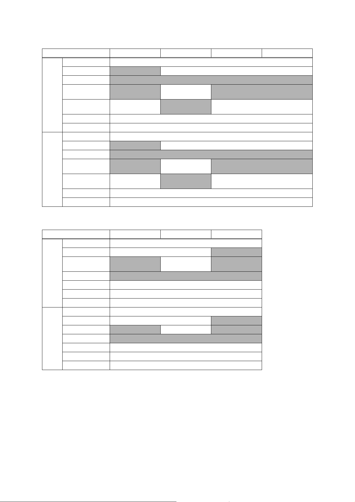
Model MFC-J6545DW MFC-J6730DW MFC-J6930DW MFC-J6935DW
<Landscape> A4, LTR, EXE
Standard Tray
Lower Tray
3rd Tray
Manual Feed Slot
MP Tray
Duplex Print
ADF (width/length) 105/148 mm to 297/431.8 mm (4.1/5.8" to 11.7/17.0")
Scanner Glass
(width/length)
<Portrait> A3, LGR, LGL, Folio, A5, A6, Photo (102 x 152 mm/4 x 6"),
Index card (127 x 203 mm/5 x 8"), Photo-L (89 x 127 mm/3.5 x 5"), Photo-2L (127 x 178 mm/5 x
7"), C5, Com-10, DL Envelope, Monarch, Mexico Legal, India Legal
N/A
N/A
<Landscape> A4,
LTR, EXE
<Portrait> A3, LGR,
LGL, Folio, A5, A6,
Photo (102 x 152 mm/
4 x 6"), Index card
(127 x 203 mm/5 x 8"),
Photo-L (89 x 127 mm/
3.5 x 5"), Photo-2L
(127 x 178 mm/5 x 7"),
Com-10, DL Envelope,
Monarch, C5, Mexico
Legal, India Legal
<PC Print> A3, LGR, LGL, Folio, A4, LTR, EXE, A5, Mexico Legal, India Legal
<Copy> A3, LGR, LGL, Folio, A4, LTR, EXE
<Landscape> A4, LTR
<Portrait> A3, LGR, LGL, Folio, Mexico Legal, India Legal
N/A
<Landscape> A4,
LTR, EXE,
<Portrait> A3, LGR,
LGL, Folio, A5, A6,
Photo (102 x 152 mm/
4 x 6"), Index card
(127 x 203 mm/5 x 8"),
Photo-L (89 x 127 mm/
3.5 x 5"), Photo-2L
(127 x 178 mm/5 x 7"),
C5, Com-10, DL
Envelope, Monarch,
Mexico Legal, India
Legal
<Landscape> A4, LTR, EXE
<Portrait> A3, LGR, LGL, Folio, A5, A6, Photo
(102 x 152 mm/4 x 6"), Index card (127 x 203
N/A
up to 297/431.8 mm (up to 11.7/17.0")
mm/5 x 8"), Photo-L (89 x 127 mm/3.5 x 5"),
Photo-2L (127 x 178 mm/5 x 7"), Com-10, DL
Envelope, Monarch, C5, Mexico Legal, India
Legal
*1
, A5, Mexico Legal, India Legal
N/A
*1
Only for US area
1-3
Confidential

Media
Sizes
Model MFC-J6945DW MFC-J6947DW MFC-T4500DW
<Landscape> A4, LTR, EXE, B5 (JIS)
*1
<Portrait> A3, LGR, B4 (JIS)*1, LGL, Folio, A5, B6 (JIS)*1, A6, Photo
Standard Tray
(102 x 152 mm/4 x 6"), Index card (127 x 203 mm/5 x 8"), Photo-L (89 x
127 mm/3.5 x 5"), Photo-2L (127 x 178 mm/5 x 7"), C5, Com-10, DL
Envelope, Monarch, Mexico Legal, India Legal, 16K (195 x 270 mm)
<Landscape> A4, LTR
Lower Tray
<Portrait> A3, LGR, LGL, Folio, Mexico Legal,
N/A
India Legal
<Landscape> A4, LTR
3rd Tray
N/A
<Portrait> A3, LGR,
LGL, Folio, Mexico
N/A
Legal, India Legal
Manual Feed Slot
<Landscape> A4, LTR, EXE, B5 (JIS)
N/A
*1
<Portrait> A3, LGR, B4 (JIS)*1, LGL, Folio, A5, B6 (JIS)*1, A6, Photo
MP Tray
Duplex Print
(102 x 152 mm/4 x 6"), Index card (127 x 203 mm/5 x 8"), Photo-L (89 x
127 mm/3.5 x 5"), Photo-2L (127 x 178 mm/5 x 7"), Com-10, DL
Envelope, Monarch, C5, Mexico Legal, India Legal, 16K (195 x 270
*2
mm)
<PC Print> A3, LGR, B4 (JIS)
*1
, B6 (JIS)*1, Mexico Legal, India Legal, 16K (195 x 270 mm)
(JIS)
*1
, LGL, Folio, A4, LTR, EXE, A5, B5
<Copy> A3, LGR, LGL, Folio, A4, LTR, EXE*3, A5, Mexico Legal, India
Legal
ADF (width/length) 105/148 mm to 297/431.8 mm (4.1/5.8" to 11.7/17.0")
Scanner Glass
(width/length)
up to 297/431.8 mm (up to 11.7/17.0")
*2
*2
*1
Only for Taiwan/China
*2
Only for China
*3
Only for US area
1-4
Confidential
Media
Weights
Media
Types
Media
Weights
Media
Types
Model HL-J6000DW HL-J6100DW HL-T4000DW
2
Standard Tray 64-220 g/m
2
Lower Tray 64-120 g/m
3rd Tray
N/A
(17-32 lb.) N/A
Manual Feed Slot
MP Tray 64-220 g/m
Duplex Print 64-120 g/m
ADF
(17-58 lb.)
64-120 g/m
(17-32 lb.)
N/A
2
(17-58 lb.)
2
(17-32 lb.)
N/A
2
N/A
Standard Tray Plain, Inkjet, Glossy, Recycled
Lower Tray Plain, Recycled
3rd Tray
N/A Plain, Recycled N/A
Manual Feed Slot
N/A
N/A
MP Tray Plain, Inkjet, Glossy, Recycled
Duplex Print Plain, Recycled
ADF
N/A
Model MFC-J3530DW MFC-J3930DW MFC-J6530DW MFC-J6535DW
2
2
2
(17-58 lb.)
N/A
2
(17-32 lb.)
2
(17-24 lb.)
64-220 g/m
(17-58 lb.)
N/A
N/A
2
N/A
64-220 g/m
(17-58 lb.)
Standard Tray 64-220 g/m
Lower Tray
N/A
64-120 g/m
(17-32 lb.)
3rd Tray
N/A
2
N/A
64-220 g/m
(17-58 lb.)
Manual Feed Slot
MP Tray
64-220 g/m
(17-58 lb.)
Duplex Print 64-120 g/m
ADF 64-90 g/m
Standard Tray Plain, Inkjet, Glossy, Recycled
Lower Tray
3rd Tray
Manual Feed Slot
MP Tray
N/A Plain, Recycled N/A
N/A
Plain, Inkjet, Glossy,
Recycled
N/A
N/A
Plain, Inkjet, Glossy,
Recycled
Plain, Inkjet, Glossy,
Recycled
N/A
N/A
Plain, Inkjet, Glossy,
Recycled
Duplex Print Plain, Recycled
ADF Plain, Recycled
2
1-5
Confidential
Media
Weights
Media
Types
Model MFC-J6545DW MFC-J6730DW MFC-J6930DW MFC-J6935DW
2
2
(17-58 lb.)
N/A
2
(17-32 lb.)
2
(17-24 lb.)
N/A
64-220 g/m
(17-58 lb.)
2
Standard Tray 64-220 g/m
Lower Tray
N/A 64-120 g/m2 (17-32 lb.)
3rd Tray
Manual Feed Slot
MP Tray
N/A
64-220 g/m
(17-58 lb.)
2
64-220 g/m
(17-58 lb.)
N/A
Duplex Print 64-120 g/m
ADF 64-90 g/m
Standard Tray Plain, Inkjet, Glossy, Recycled
Lower Tray
3rd Tray
Manual Feed Slot
MP Tray
N/A Plain, Recycled
N/A
N/A
Plain, Inkjet, Glossy,
Recycled
Plain, Inkjet, Glossy,
Recycled
N/A Plain, Inkjet, Glossy, Recycled
N/A
Duplex Print Plain, Recycled
ADF Plain, Recycled
Media
Weights
Media
Types
Model MFC-J6945DW MFC-J6947DW MFC-T4500DW
2
Standard Tray 64-220 g/m
2
Lower Tray 64-120 g/m
3rd Tray
N/A
(17-32 lb.) N/A
Manual Feed Slot
MP Tray 64-220 g/m
Duplex Print 64-120 g/m
ADF 64-90 g/m
(17-58 lb.)
64-120 g/m
(17-32 lb.)
N/A
2
(17-58 lb.)
2
(17-32 lb.)
2
(17-24 lb.)
2
N/A
Standard Tray Plain, Inkjet, Glossy, Recycled
Lower Tray Plain, Recycled
3rd Tray
N/A Plain, Recycled N/A
Manual Feed Slot
N/A
N/A
MP Tray Plain, Inkjet, Glossy, Recycled
Duplex Print Plain, Recycled
ADF Plain, Recycled
1-6
Confidential
1.3 Paper Handling
Model
Standard Tray 250 (80 g/m
Lower Tray 250 (80 g/m
Paper Input
(sheets)
3rd Tray
Manual Feed Slot
MP Tray 100 (80 g/m
ADF
Output Paper Capacity
(sheets)
Auto Paper Low Detection
Document Scan Size Sensor
Model
Standard Tray 250 (80 g/m
Lower Tray
3rd Tray
Paper Input
(sheets)
Manual Feed Slot
MP Tray
ADF
Output Paper Capacity
(sheets)
Auto Paper Low Detection
Document Scan Size Sensor
HL-J6000DW HL-J6100DW HL-T4000DW
2
)
2
) N/A
N/A 250 (80 g/m2) N/A
N/A
2
)
N/A
2
100 (Up to A4/LTR, 80 g/m
Standard Tray /
Lower Tray
Lower Tray / 3rd Tray
), 50 (Over A4/LTR, 80 g/m2)
Standard Tray /
N/A
N/A
MFC-J3530DW MFC-J3930DW MFC-J6530DW MFC-J6535DW
2
)
N/A 250 (80 g/m2) N/A
N/A
1 (Plain: 120 g/m
Glossy:
thickness 0.25 mm)
2
N/A
1 (Plain: 120 g/m
Glossy:
thickness 0.25 mm)
2
N/A
N/A 100 (80 g/m2) N/A 100 (80 g/m2)
2
50 (80 g/m
) (face up)
*sort copy up to 30
50 (80 g/m
2
) (face up)
100 (Up to A4/LTR, 80 g/m
50 (80 g/m
*sort copy up to 30
2
), 50 (Over A4/LTR, 80 g/m2)
2
) (face up)
N/A
N/A
Yes
Model
MFC-J6545DW MFC-J6730DW MFC-J6930DW MFC-J6935DW
Standard Tray 250 (80 g/m
Lower Tray
N/A 250 (80 g/m2)
3rd Tray
Paper Input
(sheets)
Manual Feed Slot
N/A
MP Tray 100 (80 g/m
ADF
Output Paper Capacity
(sheets)
Auto Paper Low Detection
Document Scan Size Sensor Yes
2
)
N/A
1 (Plain: 120 g/m
2
Glossy:
thickness 0.25 mm)
2
) N/A 100 (80 g/m2)
2
50 (80 g/m
*sort copy up to 30
) (face up)
100 (Up to A4/LTR, 80 g/m
50 (80 g/m
2
), 50 (Over A4/LTR, 80 g/m2)
N/A
N/A
N/A
2
) (face up)
Standard Tray /
Lower Tray
Yes
1-7
Confidential
Model
Standard Tray 250 (80 g/m
Lower Tray 250 (80 g/m
Paper Input
(sheets)
Output Paper Capacity
(sheets)
Auto Paper Low Detection
Document Scan Size Sensor Yes
3rd Tray
Manual Feed Slot
MP Tray 100 (80 g/m
ADF 50 (80 g/m
MFC-J6945DW MFC-J6947DW MFC-T4500DW
N/A 250 (80 g/m2) N/A
100 (Up to A4/LTR, 80 g/m
Standard Tray /
Lower Tray
1.4 LCD Panel
2
)
2
) N/A
N/A
2
)
2
) (face up)
2
), 50 (Over A4/LTR, 80 g/m2)
Standard Tray /
Lower Tray / 3rd Tray
2
50 (80 g/m
*sort copy up to 30
) (face up)
N/A
N/A
Model
Type & Size 2.7 inch TFT 3.7 inch TFT
LCD
Touch-Panel Yes
HL-J6000DW/J6100DW/T4000DW
MFC-J3530DW/J6530DW/J6730DW/T4500DW
MFC-J3930DW/J6535DW/J6545DW/J6930DW/
J6935DW/J6945DW/J6947DW
1.5 Memory
Model
Memory Capacity
(physical: Mbytes)
Memory Backup
(with Flash memory)
HL-J6000DW/
J6100DW
512 MB 128 MB 128 MB 256 MB 512 MB
HL-T4000DW
N/A Yes
MFC-J3530DW/J6530DW/
J6535DW/J6545DW/
J6730DW/T4500DW
MFC-J3930DW/
J6930DW
MFC-J6935DW/
J6945DW/
J6947DW
1-8
Confidential

1.6 Interface
HL-J6000DW/J6100DW
Model
Host Interface Hi-Speed USB 2.0
LAN
Wireless LAN
NFC
PictBridge
USB flash memory
Memory Stick Duo
Memory Stick
Extended High
Capacity
Memory Stick Pro/Pro
Duo/Micro
Acceptable
Media Cards
SD Memory Card
SDHC Memory Card
SDXC Memory Card
MultiMedia Card
MultiMedia Card plus
MultiMedia Card
mobile
MFC-J3930DW/J6930DW/J6935DW/
J6945DW/J6947DW
Yes
MFC-J3530DW/J6530DW/J6535DW/
J6545DW/J6730DW/T4500DW
Yes
Yes
N/A
Yes
N/A
N/A
N/A
N/A
N/A
N/A
N/A
N/A
N/A
HL-T4000DW
N/A
1.7 Others
Model HL-J6000DW HL-J6100DW HL-T4000DW
Operating Environment
Temperature
(Best Print Quality)
Operating Environment
Humidity
(Best Print Quality)
Power
Consumption
(Operating/
Standby/Sleep
mode/Off)
Machine Noise (Operating) 50 dBA
Machine Dimensions
Machine Weight 19.5 kg (43.0 lb) 23.2 kg (51.1 lb)
*1
As for Taiwan, refer to US area
US area
Europe 21/5.5/0.9/0.04 w
Asia/Oceania
China N/A 20/5.0/1.2/0.04 w
W575 x D477 x
H379 mm
(W22.6 x D18.8 x
H14.9 inch)
10-35 (20-33) degrees centigrade
20-80 (20-80) %
N/A 19/4.5/1.2/0.04 w
N/A 20/5.0/1.2/0.04 w
W575 x D477 x
H449 mm
(W22.6 x D18.8 x
H17.7 inch)
N/A
*1
W575 x D477 x
H310 mm
(W22.6 x D18.8 x
H12.2 inch)
16.0 kg (35.3 lb)
(For US area)
16.1 kg (35.5 lb)
(Except for US area)
1-9
Confidential

Model MFC-J3530DW MFC-J3930DW MFC-J6530DW MFC-J6535DW
Operating Environment
Temperature
(Best Print Quality)
Operating Environment
Humidity
(Best Print Quality)
Power
Consumption
(Operating/
Standby/Sleep
mode/Off)
Machine Noise (Operating) 50 dBA
Machine Dimensions
Machine Weight 19.6 kg (43.2 lb) 23.6 kg (52.0 lb)
Operating Environment
Temperature
(Best Print Quality)
Operating Environment
Humidity
(Best Print Quality)
Power
Consumption
(Operating/
Standby/Sleep
mode/Off)
Machine Noise (Operating) 50 dBA
Machine Dimensions
Machine Weight 20.1 kg (44.3 lb) 23.0 kg (50.7 lb)
US area
Europe 27/6.0/1.6/0.04 w 29/6.5/1.7/0.04 w 27/6.0/1.6/0.04 w
Asia/Oceania 27/6.0/1.6/0.04 w 29/6.5/1.7/0.04 w
China 27/6.0/1.6/0.04 w 29/6.5/1.7/0.04 w
W575 x D477 x
H305 mm
(W22.6 x D18.8 x
H12.0 inch)
Model MFC-J6545DW MFC-J6730DW MFC-J6930DW MFC-J6935DW
US area 27/5.5/1.5/0.04 w 28/6.0/1.6/0.04 w 28/5.5/1.6/0.04 w 29/6.0/1.6/0.04 w
Europe
Asia/Oceania
China
N/A 28/6.0/1.6/0.04 w 29/6.5/1.7/0.04 w
W575 x D477 x
H310 mm
(W22.6 x D18.8 x
H12.2 inch)
N/A 27/5.5/1.4/0.04 w 27/5.5/1.5/0.04 w
N/A 29/6.5/1.7/0.04 w
10-35 (20-33) degrees centigrade
20-80 (20-80) %
*1
W575 x D477 x
H374.5 mm
(W22.6 x D18.8 x
H14.7 inch)
10-35 (20-33) degrees centigrade
20-80 (20-80) %
N/A
W575 x D477 x H374.5 mm
(W22.6 x D18.8 x H14.7 inch)
27/6.0/1.6/0.04 w N/A
N/A
W575 x D477 x H305 mm
(W22.6 x D18.8 x H12.0 inch)
19.4 kg (42.8 lb)
(For US area)
19.6 kg (43.2 lb)
(Except for US area)
23.4 kg (51.6 lb)
(For US area)
23.6 kg (52.0 lb)
(Except for US area)
19.9 kg (43.9 lb)
23.5 kg (51.8 lb)
(For US area)
23.7 kg (52.2 lb)
(Except for US area)
N/A
*1
As for Taiwan, refer to MFC-J6930DW for US area
1-10
Confidential

Model MFC-J6945DW MFC-J6947DW MFC-T4500DW
Operating Environment
Temperature
(Best Print Quality)
Operating Environment
Humidity
(Best Print Quality)
Power
Consumption
(Operating/
Standby/Sleep
mode/Off)
Machine Noise (Operating) 50 dBA
Machine Dimensions
Machine Weight
*1
As for Taiwan, refer to US area
*2
As for Argentina and Chile, refer to Asia/Oceania
US area 29/6.0/1.5/0.04 w
Europe 29/6.5/1.6/0.04 w N/A
Asia/Oceania 29/6.5/1.6/0.04 w
China N/A 28/6.0/1.5/0.04 w
W575 x D477 x
H379 mm
(W22.6 x D18.8 x
H14.9 inch)
24.1 kg (53.1 lb)
(For US area)
24.2 kg (53.4 lb)
(Except for US area)
10-35 (20-33) degrees centigrade
20-80 (20-80) %
N/A 27/5.0/1.4/0.04 w
N/A 28/6.0/1.5/0.04 w
W575 x D477 x
H449 mm
(W22.6 x D18.8 x
H17.7 inch)
27.9 kg (61.5 lb)
*2
*1
W575 x D477 x
H310 mm
(W22.6 x D18.8 x
H12.2 inch)
20.4 kg (45.0 lb)
(For US area)
20.5 kg (45.2 lb)
(Except for US area)
2FAX
HL-J6000DW/
Model
Modem Speed (bps)
Transmission Speed N/A
ITU-T Group N/A
Document
COLOR FAX
(Send/Receive)
Memory
(Send/Receive)
J6100DW/
T4000DW
N/A
N/A
MFC-J3530DW/J3930DW/J6530DW/J6535DW/J6545DW/
J6730DW/J6930DW/J6935DW/J6945DW/J6947DW
33,600 (FAX)
Approx. 3 sec (ITU-T Test Chart #1, MMR)
Super G3
Yes/Yes (ITU-T color FAX)
N/A
3 PRINTER
Model All models
Print Speed ESAT (mono/color)
(based on ISO/IEC 24734)
Draft Print Speed (mono/color)
* Paper feeding time is included.
Resolution (horizontal x vertical) Up to 1,200 x 4,800 dpi
Auto Duplex Print Yes (Up to A3/LGR)
22/20 ipm
35/27 ppm
MFC-
T4500DW
N/A
1-11
Confidential

4COPY
Model
Copy Speed ESAT
(based on ISO/IEC 24735)
(mono/color)
Copy Speed FCOT
(based on ISO/
IEC 24735 Annex D)
Resolution
(horizontal x
vertical)
Auto Duplex Copy
Mono
Color
5 SCANNER
HL-J6000DW/
J6100DW/
T4000DW
N/A 12/9 ipm 15/11 ipm
N/A 6/6 sec
N/A
N/A
MFC-J3530DW/
J6530DW/
J6535DW/
J6730DW
Scan: Max. 600 x 600 dpi (FB)/Max. 300 x 600 dpi (ADF)
N/A Yes N/A Yes
MFC-J3930DW/
J6930DW/
J6935DW
Print: Max. 1,200 x 4,800 dpi
Scan: Max. 600 x 600 dpi (FB/ADF)
Print: Max. 1,200 x 4,800 dpi
MFC-J6545DW/
T4500DW
MFC-J6945DW/
J6947DW
Model
Scan speed (Mono/Color)
Multiple sheets (based on ISO/
IEC17991)
Scan speed (Duplex) (Mono/Color)
Multiple sheets (based on ISO/
IEC17991)
Resolution
(horizontal x
vertical)
Optical
Interpolated
HL-J6000DW/
J6100DW/
T4000DW
N/A
N/A
N/A
MFC-J3530DW/J6530DW/
J6535DW/J6545DW/J6730DW/
T4500DW
A4 portrait: 18/18 ipm
A4 landscape: 11/11 ipm
A3: 8/8 ipm
N/A
FB: 1,200 x 2,400 dpi (Mono) / 1,200 x 1,200 dpi (Color)
ADF: 600 x 600 dpi (Mono) / 300 x 600 dpi (Color)
For Windows Vista/7/8/8.1/10,
up to 19,200 x 19,200 dpi with Scanner Utility
MFC-J3930DW/J6930DW/
J6935DW/J6945DW/J6947DW
A4 portrait: 36/36 ipm
A4 landscape: 22/22 ipm
A3: 16/16 ipm
1-12
Confidential

6 SOFTWARE
Model
Driver
Support OS
Version
HL-J6000DW/J6100DW/T4000DW
MFC-J6545DW/J6945DW/J6947DW/T4500DW
Windows
Macintosh OS X v10.11.6, macOS v10.12.x/10.13.x OS X v10.9.5/10.10.x/10.11.x
Server 2008/2008 R2/2012/2012 R2/2016
Windows 7 SP1/8/8.1/10
MFC-J3530DW/J3930DW/J6530DW/J6535DW/
J6730DW/J6930DW/J6935DW
Windows Vista/7/8/8.1/10
Windows Server 2008/2008 R2/2012/2012 R2
7NETWORK
7.1 Network
Model
Internet FAX (Firmware)
(versionT37)
HL-J6000DW/J6100DW/T4000DW
MFC-J6545DW/T4500DW
N/A Yes (Download) Yes
7.2 Wired
Model
Model Name (Ethernet) Embedded (NC-420h) Embedded (NC-380h)
Network Connection (Ethernet) Ethernet 10/100BASE-TX Auto Negotiation
HL-J6000DW/J6100DW/T4000DW
MFC-J6545DW/J6945DW/J6947DW/
T4500DW
MFC-J3530DW/J3930DW/J6530DW/
J6535DW/J6730DW/J6930DW/J6935DW
MFC-J3530DW/J3930DW/J6530DW/
J6535DW/J6730DW/J6930DW/J6935DW
MFC-J6945DW/
J6947DW
7.3 Wireless
Model
Model Name (Wireless) Embedded (NC-430w) Embedded (NC-390w)
Network Connection
(Wireless)
Wireless Security
AOSS
Setup Support
Utility
WPS
(Wifi Protected
Setup)
HL-J6000DW/J6100DW/T4000DW
MFC-J6545DW/J6945DW/J6947DW/
T4500DW
IEEE 802.11b/g/n (Infrastructure) IEEE 802.11g/n (Wi-Fi Direct)
WEP 64/128 bit, WPA-PSK (TKIP/AES), WPA2-PSK (TKIP/AES)
* Wi-Fi Direct supports WPA2-PSK (AES) only
MFC-J3530DW/J3930DW/J6530DW/
J6535DW/J6730DW/J6930DW/J6935DW
N/A
Yes
1-13
Confidential

8 SUPPLIES/OPTIONS
Model
Bundled Cartridge
(BK/CL)
Ink
Cartridge
Yield @
ISO
pattern
(Pages)
Ink Bottle
Yield @
ISO
pattern
(Pages)
Storage Condition of Ink
Cartridge
Supply High Yield
Cartridge (BK/CL)
Supply Super High
Yield Cartridge
(BK/CL)
Bundled Bottle
(BK/CL)
Supply High Yield
Bottle (BK/CL)
HL-J6000DW/
J6100DW/
MFC-
J6947DW
2,250/975
3,000/1,500
6,000/5,000
N/A
N/A
(Temperature) Normal condition: -20 to 40°C (Humidity) Normal condition: 20 to 80%
* At the temperature of 40 to 50°C and the humidity of 80 to 95%: Up to 5 days
* At the temperature of 40 to 60°C and the humidity of Non control condition: Up to 5 days
HL-
T4000DW/
MFC-
T4500DW
N/A
N/A
N/A 3,000/1,500 6,000/5,000
5,850/
4,250
6,500/
5,000
MFC-J3530DW/
J3930DW/
J6530DW/
J6730DW/
J6930DW
357/357
(Except for China)
2,400/975
(For China)
550/550
(Except for China)
N/A (For China)
MFC-
J6535DW/
J6935DW
2,400/975
550/550
(For Europe)
N/A (Except
for Europe)
N/A
N/A
MFC-J6545DW/J6945DW
MFC-J6545DW/J6945DW:
4,000/3,700
(For U.S.A. and Canada)
2,250/975
(Except for U.S.A. and
Canada)
MFC-J6545DW XL:
1 set of 4,000/3,700 and
1 set of 5,100/3,750
3,000/1,500
9 SERVICE INFORMATION
Model All models
Monthly Volume Up to 30,000 pages
Machine Life 100,000 pages or 5 years
MTBF (Mean Time Between Failures) 4,000 hours
MTTR (Mean Time To Be Repaired) 30 minutes
1-14
Confidential

10 PAPER
10.1 Paper
Paper type and size for each operation
Usage
Paper Type Paper Size
Ledger
Letter
A3
A4
Legal
Mexico legal
India legal
Cut-Sheet
Cards
Envelopes
*1
PDF Print is available only for HL-J6000DW/J6100DW, MFC-J6935DW/J6945DW/J6947DW.
*2
Supported only in some countries.
Folio
*2
16K
Executive
JIS B4
JIS B5
JIS B6
A5
A6
Photo
Photo L
Photo 2L
Index Card
C5 Envelope
DL Envelope
Com-10
Monarch
11 x 17 in. (279.4 x 431.8 mm)
8 1/2 x 11 in. (215.9 x 279.4 mm)
11.7 x 16.5 in. (297 x 420 mm)
8.3 x 11.7 in. (210 x 297 mm)
8 1/2 x 14 in. (215.9 x 355.6 mm)
8.5 x 13.38 in. (215.9 x 339.85 mm)
8.46 x 13.58 in. (215 x 345 mm)
8 1/2 x 13 in. (215.9 x 330.2 mm)
7.7 x 10.6 in. (195 x 270 mm)
7 1/4 x 10 1/2 in. (184.1 x 266.7 mm)
*2
10.1 x 14.3 in. (257 x 364 mm)
*2
7.2 x 10.1 in. (182 x 257 mm)
*2
5.04 x 7.17 in. (128 x 182 mm)
5.8 x 8.3 in. (148 x 210 mm)
4.1x 5.8 in. (105 x 148 mm)
4 x 6 in. (10 x 15 cm)
3 1/2 x 5 in. (9 x 13 cm)
5 x 7 in. (13 x 18 cm)
5 x 8 in. (13 x 20 cm)
6.4 x 9 in. (162 x 229 mm)
4.3 x 8.7 in. (110 x 220 mm)
4 1/8 x 9 1/2 in. (104.7 x 241.3 mm)
3 7/8 x 7 1/2 in. (98.4 x 190.5 mm)
Fax Copy
Yes
Yes
Yes
Yes
Yes
Yes
Yes
Yes
---
---
---
---
---
---
---
---
---
---
---
---
---
---
---
Yes
Yes
Yes
Yes
Yes
Yes
Yes
Yes
--Yes
---
---
--Yes
Yes
Yes
---
---
---
---
---
---
---
Direct Print
JPEG
Print
Yes
Yes
Yes
Yes
---
---
---
---
---
---
---
---
---
---
--Yes
--Yes
--
---
---
---
---
Yes
Yes
Yes
Yes
Yes
Yes
Yes
Yes
--Yes
---
---
--Yes
Yes
---
---
---
---
---
---
---
--
PDF
Print
-
Printer
*1
Yes
Yes
Yes
Yes
Yes
Yes
Yes
Yes
Yes
Yes
Yes
Yes
Yes
Yes
Yes
Yes
Yes
Yes
Yes
Yes
Yes
Yes
Yes
Paper weight and thickness
Paper Type Weight Thickness
2
Plain Paper, Recycled Paper 17 to 32 lb (64 to 120 g/m
Cut-Sheet
Cards
Envelopes 20 to 25 lb (80 to 95 g/m
*1
BP71 69 lb (260 g/m2) paper is specially designed for Brother inkjet machines.
*2
Up to 12 mil (Up to 0.3 mm) for MP Tray.
*3
Up to 58 lb (Up to 220 g/m2) for MP Tray.
Inkjet Paper 17 to 53 lb (64 to 200 g/m
Glossy Paper
Photo Card
Index Card Up to 32 lb (Up to 120 g/m
*1,2
*1,2,3
Up to 58 lb (Up to 220 g/m2) Up to 10 mil (Up to 0.25 mm)
Up to 53 lb (Up to 200 g/m2) Up to 10 mil (Up to 0.25 mm)
1-15
) 3 to 6 mil (0.08 to 0.15 mm)
2
) 3 to 10 mil (0.08 to 0.25 mm)
2
) Up to 6 mil (Up to 0.15 mm)
2
) Up to 20 mil (Up to 0.52 mm)
Confidential

Paper capacity of the paper trays
Paper size Paper types No. of sheets
<Landscape>
Letter, Executive, A4, JIS B5
Standard Tray
<Portrait>
Ledger, A3, JIS B4
India Legal, Folio, A5, A6, Envelopes (C5, Com-10,
DL, Monarch), Photo, Photo L, Photo 2L, Index
Card,16K
*1
<Landscape>
Letter, A4
Lower Tray
<Portrait>
Ledger, A3, JIS B4
Legal, Folio
<Landscape>
Letter, Executive, A4, JIS B5
MP Tray
*3
<Portrait>
Ledger, A3, JIS B4
India Legal, Folio, A5, A6, Envelopes (C5, Com-10,
DL, Monarch), Photo, Photo L, Photo 2L, Index
Card,16K
*1
<Landscape>
Letter, Executive, A4, JIS B5
Manual Feed Slot
<Portrait>
Ledger, A3, JIS B4
India Legal, Folio, A5, A6, Envelopes (C5, Com-10,
DL, Monarch), Photo, Photo L, Photo 2L, Index
Card,16K
*1
<Landscape>
Letter, A4
3rd Tray
<Portrait>
Ledger, A3, JIS B4
Legal, Folio
*1
Supported only in some countries.
*2
When using plain paper 20 lb (80 g/m2).
*3
MP tray is recommended for glossy paper.
*1
, JIS B6*1, Legal, Mexico Legal,
*1
, Legal, Mexico Legal, India
*1
, JIS B6*1, Legal, Mexico Legal,
*1
, JIS B6*1, Legal, Mexico Legal,
*1
, Legal, Mexico Legal, India
*1
Plain Paper, Recycled Paper 250
*2
Inkjet Paper 20
Glossy Paper, Photo 20
Index Card 30
Envelopes 10
Plain Paper, Recycled Paper 250
Plain Paper, Recycled Paper 100
*1
Inkjet Paper
Glossy Paper, Photo
*2
*2
20 (Up to Letter/A4)
5 (Over Letter/A4)
20 (Up to Letter/A4)
5 (Over Letter/A4)
Index Card 50
Envelopes
*1
20 (Up to Letter/A4)
5 (Over Letter/A4)
Plain Paper, Recycled Paper,
Inkjet Paper, Glossy Paper,
1
Photo and Envelopes
Plain Paper, Recycled Paper 250
*2
Recommended print media
Brother paper
Paper Type Item
Premium Plus Glossy Photo
- Ledger
- Letter
- 4" x 6"
Plain Inkjet
- Ledger
- A3 Plain
- A3 Glossy Photo
- A3 Inkjet (Matte)
- A4 Plain
- A4 Glossy Photo
- A4 Inkjet (Matte)
- 10 x 15 cm Glossy Photo
BP71GLGR
BP71GLTR
BP71GP20
BP60PLGR (U.S.A. only)
BP60PA3
BP71GA3
BP60MA3
BP60PA
BP71GA4
BP60MA
BP71GP
1-16
Confidential

Handle and Use Print Media
Self-adhesive Double flaps
Store paper in its original packaging and keep it sealed. Keep the paper flat and away from
moisture, direct sunlight and heat.
Avoid touching the shiny (coated) side of the photo paper.
IMPORTANT
DO NOT use the following kinds of paper:
- Damaged, curled, wrinkled, or irregularly shaped
1: 0.08 in.(2mm) or greater curl may cause jams to occur.
- Extremely shiny or highly textured
- Paper that cannot be arranged uniformly when stacked
- Paper made with a short grain
DO NOT use envelopes that:
- Are loosely constructed
- Have windows
- Are embossed (have raised writing on them)
- Have clasps or staples
- Are pre-printed on the inside
- Are self-adhesive
- Have double flaps
1-17
Confidential

10.2 Unprintable Area
Cut-Sheet Paper Envelopes
The unprintable area depends on the settings in the applicatio n you are using. The figures
below show the unprintable areas on cut-sheet paper and envelopes. The machine can print in
the shaded areas of cut-sheet paper only when the Borderless print feature is available and
turned on.
Cut-Sheet 0.12 in. (3 mm) 0.12 in. (3 mm) 0.12 in. (3 mm) 0.12 in. (3 mm)
Envelopes 0.47 in. (12 mm) 0.12 in. (3 mm) 0.47 in. (12 mm) 0.12 in. (3 mm)
Top (1) Left (2) Bottom (3) Right (4)
Note: The Borderless print feature is not available for envelopes, 2-sided printing and some
paper sizes, such as Legal and Executive.
1-18
Confidential

CHAPTER 2 TROUBLESHOOTING
1 INTRODUCTION
This section gives the service personnel some of the troubleshooting procedures to be
followed if an error or malfunction occurs with the machine. It is impossible to anticipate
all of the possible problems which may occur in future and determine the
troubleshooting procedures, so this section covers some sample problems. However,
those samples will help service personnel pinpoint and repair other defective elements
if he/she analyzes and examines them well.
1.1 Precautions
For precautions in a check based on troubleshooting, see "Precautions for
Troubleshooting and/or Disassembly/Assembly". (Refer to page: x)
1.2 Initial Check
Prior to proceeding to the troubleshooting procedures, make the following initial
checks:
Environmental conditions
(1) The machine is placed on a flat, firm surface.
(2) The machine is used in clean environment with temperature (10 to 35 degree-C)
and humidity (20 to 80 %.)
(3) The machine is not exposed to direct sunlight, excessive heat, moisture, or dust.
(4) The machine is transported in level.
Power requirements
(1) The power requirements described in label of the machine is supplied. Its variation
is within +/-10% of the rated voltage.
(2) All cables and harnesses are firmly connected.
(3) The fuses are not blown.
Recording paper
(1) A recommended type of paper is being used (refer to Chapter 1, Section 10 "PAPER")
(2) The recording paper is not dampened.
Consumable Parts
(1) Ink cartridge (4 colors) is correctly set, or ink is properly refilled.
Head/carriage unit
(1) Repeat purge action (maintenance code 76) for a couple of times. (Refer to
Chapter 5, Section 1.3.28 "Purge Operation (Maintenance mode 76)".)
Others
(1) Low temperature
Motor may not run correctly due to excessive load for each drive in low
temperature environment. Warm the room temperature in such case.
2-1
Confidential

Cleaning
WARNING
(1) Use a soft dry lint-free cloth.
WARNING
DO NOT use flammable solvent such as alcohol, benzine, thinner to clean the body
of the machine. DO NOT use near by.
2-2
Confidential

2OVERVIEW
* Duplex scanning models only
Document tray
Document pick-up roller
ADF separation pad
Document separation roller
Second side CIS unit *
Document feed roller 1
Document
Document scanning position actuator
First side CIS unit
Document ejection roller
ADF document width actuator
ADF document detection actuator
feed roller 2
2.1 Cross-section Drawings
2.1.1 Document scanning
Fig. 2-1
2-3
Confidential

2.1.2 Printer part
MP tray ASSY
Registration
Paper feed roller
Head/carriage unit
Paper
Switchback
Switchback
Control
Duplex paper
T1 paper
T1 bank
T3 paper
T2 bank ASSY
MP bank ASSY
MP paper pull-in roller
MP paper detection actuator
feed roller
ASSY
pull-in roller
roller
actuator
actuator
ejection roller
panel
ASSY
pull-in roller
T3 bank ASSY
3rd tray paper
pull-in actuator
T2 paper
pull-in roller
Intermediate roller
Fig. 2-2
2-4
Confidential

2.2 Document Feeding Path/Recording Paper Feeding Path
Document feeding path during ADF scanning
Feeding path from MP tray
Feeding path
Feeding path
during duplex-printing
from Paper tray#1
Feeding path
from Paper tray#2
Feeding path
from Paper tray#3
2.2.1 Document Feeding Path
Fig. 2-3
2.2.2 Recording Paper Feeding Path
Fig. 2-4
2-5
Confidential

2.3 Parts Names and Functions
■ Document scanning and feeding
Parts Names Functions
ADF document detection
actuator
This detects whether documents are set on the
document tray.
ADF document width actuator Identify the document size.
Document pick-up roller
This pulls documents loaded in the document tray into
the ADF.
Document separation roller
ADF separation pad
This separates documents sent by the document
pick-up roller in single sheet.
Document feed roller 1, 2 This feeds a document to the CIS unit.
Document scanning position
actuator
This detects the leading edge and the ending edge
of the document, adjusting the scanning position
on the first side and second side.
This detects paper jamming in the ADF.
Document ejection roller This ejects the scanned document to the document
ejection tray.
■ Printing and paper feeding
Parts Names Functions
T1/T2 paper pull-in roller This feeds the recording paper from the paper tray
#1#2 to the paper feed roller.
After the registration actuator detects the leading
edge of the paper, it pushes the recording paper
against the reverse-rotating or stopped paper feed
roller, and correct inclination of the paper.
Registration actuator This detects the leading edge of recording paper,
controlling the printing start position.
This detect the leading edge/ending edge of
recording paper, identifying the recording paper
size.
This detects paper jamming in the rear.
Paper feed roller This reverses the rotation or stops when correcting
inclination of the paper with the T1/T2 paper pull-in
roller, the duplex paper feed roller and the
intermediate roller.
It feeds the recording paper to the printing start
position after correction.
Paper ejection roller This feeds printed recording paper to the
switchback roller.
2-6
Confidential

Parts Names Functions
Switchback actuator This detects whether the printed recording papers
are ejected.
This detects the ending edge of recording paper
after printing the first side when duplex-printing,
adjusting timing to reverse the switchback roller
rotation.
This detects paper jamming in the ejector.
Switchback roller
This ejects the recording paper to the output paper tray.
During duplex-printing, after feeding some of the
recording papers printed in the first side to the
switchback roller, its rotation is reversed to feed the
recording paper to the duplex-printing path.
Duplex paper feed roller During duplex-printing, this feeds the recording
paper that are fed in the duplex paper path to the
paper feed roller.
After the registration actuator detects the leading
edge of the paper, it pushes the recording paper
against the stopping paper feed roller, and corrects
inclination of the paper.
MP paper pull-in roller This feeds the recording paper from the MP tray to
the paper feed roller.
After the registration actuator detects the leading
edge of the paper, it pushes the recording paper
against the stopping or reverse-rotating paper feed
roller, and corrects inclination of the paper.
MP paper detection actuator This detects whether the recording paper are set
on the MP tray.
T3 paper pull-in roller This feeds the recording paper from the paper tray
#3 to the Intermediate roller.
After the 3rd tray paper pull-in actuator detects the
leading edge of the paper, it pushes the recording
paper against the reverse-rotating or stopped
intermediate roller, and corrects inclination of the
paper.
Intermediate roller This feeds the recording paper from the T3 paper
pull-in roller to the paper feed roller.
After the registration actuator detects the leading
edge of the paper, it pushes the recording paper
against the reverse-rotating or stopped paper feed
roller, and corrects inclination of the paper.
3rd tray paper pull-in actuator This detects the leading edge of recording paper
and switches drive from the T3 paper pull-in roller
to intermediate roller.
2-7
Confidential

2.4 Block Diagram
Print Engine 1
PF Encoder Sensor PCB
Switchback Sensor PCB
T1 Detecon Sensor
T1 Paper Remaining Sensor PCB
T2 Detecon Sensor
T2 Paper Remaining Sensor PCB
MP Paper Detecon Sensor PCB
3rd Tray
ASF Motor Unit
ASF
Motor
ASF Encoder Sensor
T3 Paper Remaining Sensor PCB
3rd Tray Paper Pull-in Sensor PCB
T3 Detecon Sensor
Document Scanner Sensor
Print Engine 2
Paper Feed Motor
Carriage Motor
ASF Motor Unit
ASF
Motor
ASF Encoder Sensor PCB
Registraon Sensor PCB
Purge Cam Sensor PCB
Cap Cam Sensor PCB
ADF Unit
ADF Document Size Sensor
ADF Document Detecon
Sensor/ADF Document
Width SensorPCB
Document Scanning Posion
Sensor PCB
ADF Cover Sensor
3rd Tray Relay
PCB
Motor
Driver IC
Power Supply
PCB
AC line
ADF
Motor
AFE/
LED Driver
ADC
USB
Host
USB
Second
Side CIS
Wireless
LAN PCB
AFE/
LED Driver
ASIC
Serial
ROM
Ink Cartridge
Cover Sensor
Scanner Unit
First Side
CIS
Motor
EEPROM
DDR3
LAN
(MAC)
Serial
ROM
(Backup)
Control Panel ASSY
LCD
FB
Touch
Panel
LCD PCB
Document Cover Sensor
FB Document Size Sensor
USB
LAN
(PHY)
AMP
Main PCB
Cerfi.
IC
PNL9
NFC
PCB
Panel PCB
OnOff SW
PC
Ethernet
Modem PCB
SDAA
Modem
Head/Carriage Unit
Print Head unit
Head IC ((COF)
Speaker
Head FPC
Head Thermistor
Carriage PCB
CR Encoder Sensor
Paper Width Sensor
INK Refill ASSY
Regular Ink cartridge model
Ink Remaining Sensor
Ink Cartridge Sensor PCB
Ink Remaining Sensor
Ink Cartridge Detecon
Sensor
Thermistor
Humidity Sensor
Cerficaon Chip PCB
Ink tank model
Ink Remaining Sensor
PCB (BK)
PCB
IC
MODULE
Tel line
Ext Tel line
Fig. 2-5
Simple Ink cartridge model
Cerficaon Chip PCB
Ink Remaining Sensor PCB
Ink Cartridge Sensor PCB
Ink Cartridge Detecon
Sensor
Thermistor
2-8
Confidential

2.5 Components
ADF unit
Document scanner unit
Upper cover
Harness cover
Head/carriage unit
Maintenance unit
Ink refill ASSY
Modem PCB
Main PCB
Wireless LAN
Ink cartridge
Control panel ASSY
Ink cartridge cover
Engine related
PCB ASSY
cover sensor ASSY
Paper tray
Paper tray ASSY #2/#3
Front cover L
Power supply
Registration sensor
PCB ASSY
PF encoder
PF encoder
sensor PCB
sensor harness
PCB ASSY
Lower power
supply frame
Lower cover
Flushing box
Jam clear cover
FB stopper
MP tray ASSY
Edge cover
FFC separator
Main PCB frame
Switchback frame ASSY
Paper feed arm
parts
Output
paper tray
Ink absorber box
Lower tray unit
ASSY
frame ASSY
(with Lower tray)
Ink absorber box
(without
Lower tray)
(for Ink cartridge model)
Ink refill ASSY
(for Ink tank model)
Tank case
ASSY
ASSY #1
3rd tray unit
3rd tray relay PCB
Fig. 2-6
2-9
Confidential

3 ERROR INDICATION
To help the user or the service personnel promptly locate the cause of a problem (if
any), the machine incorporates the self-diagnostic functions which display error
messages for equipment errors.
3.1 Error Code
Error
Code
0D00 Paper jam during duplex-printing
- The recording papers are fed in reverse on the platen when switchback
drive is started, triggering switchback sensor as paper feeding condition.
0E00 Defective during duplex-printing
- Switchback sensor detects paper feed condition at out of specified
timing during switchback.
1300 Defective during duplex-printing
- Registration sensor detects paper feed condition at out of specified timing
during switchback.
1500 Paper jam during duplex ejecting
- Recording paper is not able to be ejected since it is longer than 840 mm
when ejecting the paper. (The registration sensor stays in the paper
feeding condition during ejecting.)
1700 Recording paper size error (duplex-printing/duplex-copying)
- Paper width is narrower than 95.5 mm (detection by paper width
sensor)
- Paper length is longer than 461.8 mm (detection by registration sensor)
- Paper length is shorter than 143.5 mm (detection by registration sensor)
1800 Paper jam during duplex-printing
- Registration sensor does not detect paper feed within specified pulse
numbers in the second side paper re-feed.
2000 Cannot identify a black ink cartridge.
- The ink cartridge detection sensor and the ink remaining sensor are
detecting.
2001 Cannot identify a yellow ink cartridge.
- The ink cartridge detection sensor and the ink remaining sensor are
detecting.
2002 Cannot identify a cyan ink cartridge.
- The ink cartridge detection sensor and the ink remaining sensor are
detecting.
2003 Cannot identify a magenta ink cartridge.
- The ink cartridge detection sensor and the ink remaining sensor are
detecting.
2100 Black ink cartridge side IC chip relation defective
- Detecting setting wrong color
2101 Yellow ink cartridge side IC chip relation defective
- Detecting setting wrong color
2102 Cyan ink cartridge side IC chip relation defective
- Detecting setting wrong color
2103 Magenta ink cartridge side IC chip relation defective
- Detecting setting wrong color
Contents
Refer to
page:
2-25
2-25
2-26
2-26
2-27
2-27
2-28
2-28
2-28
2-28
2-28
2-28
2-28
2-28
2-10
Confidential

Error
Code
Contents
Refer to
page:
2200 Black ink cartridge side IC chip relation defective
- It is judged as incompatible ink cartridge is loaded.
2201 Yellow ink cartridge side IC chip relation defective
- It is judged as incompatible ink cartridge is loaded.
2202 Cyan ink cartridge side IC chip relation defective
- It is judged as incompatible ink cartridge is loaded.
2203 Magenta ink cartridge side IC chip relation defective
- It is judged as incompatible ink cartridge is loaded.
2300 Black ink cartridge side IC chip relation defective
- It is judged as optional ink cartridge has been loaded before the initial
installation is started.
2301 Yellow ink cartridge side IC chip relation defective
- It is judged as optional ink cartridge has been loaded before the initial
installation is started.
2302 Cyan ink cartridge side IC chip relation defective
- It is judged as optional ink cartridge has been loaded before the initial
installation is started.
2303 Magenta ink cartridge side IC chip relation defective
- It is judged as optional ink cartridge has been loaded before the initial
installation is started.
2400 Black ink cartridge side IC chip relation defective
- Identification no match
- Judging as incompatible ink cartridge
2401 Yellow ink cartridge side IC chip relation defective
- Identification no match
- Judging as incompatible ink cartridge
2402 Cyan ink cartridge side IC chip relation defective
- Identification no match
- Judging as incompatible ink cartridge
2403 Magenta ink cartridge side IC chip relation defective
- Identification no match
- Judging as incompatible ink cartridge
2500
2501
2502
2503
Cannot communicate with b
Cannot communicate with y
Cannot communicate with
lack
ellow
cyan
Cannot communicate with m
ink cartridge IC chip (ink cartridge side.)
ink cartridge IC chip (ink cartridge side.)
ink cartridge IC chip (ink cartridge side.)
agenta
ink cartridge IC chip (ink cartridge side.)
2600 Black ink cartridge reaches its replacement period.
Black ink reaches its refill period.
- After judging as no ink by the ink remaining sensor, ink discharged for
specified times.
2601 Yellow ink cartridge reaches its replacement period.
- After judging as no ink by the ink remaining sensor, ink discharged for
specified times.
2602 Cyan ink cartridge reaches its replacement period.
- After judging as no ink by the ink remaining sensor, ink discharged for
specified times.
2603 Magenta ink cartridge reaches its replacement period.
- After judging as no ink by the ink remaining sensor, ink discharged for
specified times.
2700 Black ink cartridge will reach its replacement period.
Black ink will reach its refill period soon.
- After judging as no ink by the ink remaining sensor, ink discharged for
less than specified times.
2-29
2-29
2-29
2-29
2-29
2-29
2-29
2-29
2-30
2-30
2-30
2-30
2-30
2-30
2-30
2-30
2-31
2-31
2-31
2-31
2-31
2-11
Confidential

Error
Code
2A00 No black ink cartridge loaded.
Contents
Refer to
page:
2-32
- Detected by the ink cartridge detection sensor.
2A01 No yellow ink cartridge loaded.
2-32
- Detected by the ink cartridge detection sensor.
2A02 No cyan ink cartridge loaded.
2-32
- Detected by the ink cartridge detection sensor.
2A03 No magenta ink cartridge loaded.
2-32
- Detected by the ink cartridge detection sensor.
2B00 Black ink cartridge ink remaining counter error 2-32
2B01 Yellow ink cartridge ink remaining counter error 2-32
2B02 Cyan ink cartridge ink remaining counter error 2-32
2B03 Magenta ink cartridge ink remaining counter error 2-32
2E00 Cannot communicate with ink cartridge IC chip (machine body side.) 2-33
2F00 Ink cartridge cover sensor detects opened cover state. 2-33
3000 Carriage does not move.
2-33
- Detected by the CR encoder sensor.
3100 Carriage cannot detect origin.
2-34
- Detected by the CR encoder sensor.
3200 Head capping is unable. 2-34
3500 Abnormal stop of head/carriage unit being driven
2-35
- Causes other than paper jam when ink is not discharging
3800 Abnormal stop of head/carriage unit being driven
2-35
- Caused by paper jam when ink is not discharging
3B00 Abnormal stop of head/carriage unit being driven
2-35
- Causes other than paper jam when ink is discharging
3C00 Abnormal stop of head/carriage unit being driven
2-36
- Caused by paper jam when ink is discharging
3E00 Defective occurs in the ASF motor, carriage motor or paper feed motor. 2-36
3F00 Carriage motor cannot stop. 2-37
4000 Casing internal thermistor defective
2-37
- Casing internal thermistor detects -20 degree-C or less, or 80 degree-C
or more when power is ON.
4200 Head voltage does not turn OFF. 2-37
4300 Head thermistor defective
2-38
- Head thermistor detects -20 degree-C or less, or 80 degree-C or more
when power is ON.
4400
Head driver IC detects abnormal temperature during operation or stand-by.
2-38
4600 Purge count or flushing count overflown. 2-38
4800 Head flat cable detected to be not correctly inserted. 2-38
4900 Head voltage does not raise. 2-39
4C00 ASIC thermistor error
2-39
- The ASIC thermistor detected a temperature of -21 degree-C or less, or
125 degree-C or greater, when the machine was turned on.
2-12
Confidential

Error
Code
Contents
Refer to
page:
4C01 Compound IC thermistor error
2-39
- The compound IC thermistor detected a temperature of -21 degree-C or
less, or 125 degree-C or greater, when the machine was turned on.
4E00 Head voltage remains ON and does not turn OFF even after 15 minutes
2-39
have passed.
4F00 Head voltage drops too quick. 2-40
5000 The purge cam switch is not switching ON/OFF. 2-40
5200 Failed to detect the origin of the purge cam. 2-40
5A00 Abnormal stop of purge cam being driven 2-40
5B00
5D00 Excessive current protection activated for the head driver IC during purge
Pump of maintenance unit stopped abnormally during exhaustion/suction.
2-40
2-40
cam operation.
5E00 Excessive current protection activated for the head driver IC during pump
2-40
operation.
6700 T1 detection sensor detects no paper tray #1 state. 2-41
6701 T2 detection sensor detects no paper tray #2 state. 2-41
6702 T3 detection sensor detects no paper tray #3 state. 2-41
6F00 ASF motor cannot stop. 2-42
6F01 ASF encoder sensor cannot detect rotation of the ASF motor. 2-42
7000 Failed to detect ON/OFF of the purge cam. 2-42
7200
Failed to detect the origin of the purge cam.
2-42
7500 Cap cam cannot shift to head capping position. 2-42
7600 Cap cam cannot shift to head uncapping position. 2-42
7A00 Purge cam rotation error (capping CW) 2-42
7D00 Current protection activated for the cap driver IC. 2-42
7E00 Head property information not input. 2-42
8000 Recording paper size error (during FAX/list printing) (Only the models
2-43
with single tray) The registration sensor and paper width sensor detect
that the size of the loaded recording paper does not match the recording
paper size setting.
8001 Paper tray #1 recording paper size error (during FAX/list printing) (Only
2-43
the models with multiple trays) The registration sensor and paper width
sensor detect that the size of the loaded recording paper does not match
the recording paper size setting.
8002 Paper tray #2 recording paper size error (during FAX/list printing) (Only
2-43
the models with multiple trays) The registration sensor and paper width
sensor detect that the size of the loaded recording paper does not match
the recording paper size setting.
8003
Paper tray #3 recording paper size error (during FAX/list printing)
2-43
(Only the models with multiple trays) The registration sensor and
paper width sensor detect that the size of the loaded recording
paper does not match the recording paper size setting.
8004 MP tray recording paper size error (during FAX/list printing) (Only the
models with multiple trays) The registration sensor and paper width
sensor detect that the size of the loaded recording paper does not match
the recording paper size setting.
2-43
2-13
Confidential

Error
Code
Contents
Refer to
page:
8101 Recording paper size error (during FAX/list printing) (Only the models
with single tray) The registration sensor and paper width sensor detect
recording paper smaller than the setting size.
8102 Recording paper size error (during PC printing) (Only the models with
single tray) The registration sensor and paper width sensor detect
recording paper smaller than the setting size.
8103 Recording paper size error (during copy printing) (Only the models with
single tray) The registration sensor and paper width sensor detect
recording paper smaller than the setting size.
8104 Paper tray #1 recording paper size error (during FAX/list printing) (Only
the models with multiple trays) The registration sensor and paper width
sensor detect recording paper smaller than the setting size.
8105 Paper tray #2 recording paper size error (during FAX/list printing) (Only
the models with multiple trays) The registration sensor and paper width
sensor detect recording paper smaller than the setting size.
8106 Paper tray #3 recording paper size error (during FAX/list printing) (Only
the models with multiple trays) The registration sensor and paper width
sensor detect recording paper smaller than the setting size.
8107 MP tray recording paper size error (during FAX/list printing) (Only the
models with multiple trays) The registration sensor and paper width
sensor detect recording paper smaller than the setting size.
8108 Paper tray #1 recording paper size error (during PC printing) (Only the
models with multiple trays)The registration sensor and paper width
sensor detect recording paper smaller than the setting size.
8109 Paper tray #2 recording paper size error (during PC printing) (Only the
models with multiple trays) The registration sensor and paper width
sensor detect recording paper smaller than the setting size.
810A Paper tray #3 recording paper size error (during PC printing) (Only the
models with multiple trays) The registration sensor and paper width
sensor detect recording paper smaller than the setting size.
810B MP tray recording paper size error (during PC printing) (Only the models
with multiple trays) The registration sensor and paper width sensor detect
recording paper smaller than the setting size.
810C
Paper tray #1 recording paper size error
(during copy printing)
(Only the
models with multiple trays) The registration sensor and paper width
sensor detect recording paper smaller than the setting size.
810D
Paper tray #2 recording paper size error
models with multiple trays)
The registration sensor and paper width
(during copy printing) (Only the
sensor detect recording paper smaller than the setting size.
810E
Paper tray #3 recording paper size error
models with multiple trays)
The registration sensor and paper width
(during copy printing) (Only the
sensor detect recording paper smaller than the setting size.
810F MP tray recording paper size error (during copy printing) (Only the
models with multiple trays) The registration sensor and paper width
sensor detect recording paper smaller than the setting size.
8110 The paper size and paper type of each tray set during print setting are
different from before printing. This error occurs when the paper tray #1
has been specified as a pickup tray with the highest priority and plain
paper has been specified as the paper type in auto tray switching print.
2-43
2-43
2-43
2-43
2-43
2-44
2-44
2-44
2-44
2-44
2-44
2-44
2-44
2-44
2-45
2-46
2-14
Confidential

Error
Code
Contents
Refer to
page:
8111 The paper size and paper type of each tray set during print setting are
2-46
different from before printing. This error occurs when the MP tray or
manual feed slot has been specified as a pickup tray with the highest
priority and plain paper has been specified as the paper type in auto tray
switching print.
8112 The paper size and paper type of each tray set during print setting are
2-46
different from before printing. This error occurs when the paper tray #1
has been specified as a pickup tray with the highest priority and inkjet
paper has been specified as the paper type in auto tray switching print.
8113 The paper size and paper type of each tray set during print setting are
2-46
different from before printing. This error occurs when the MP tray or
manual feed slot has been specified as a pickup tray with the highest
priority and inkjet paper has been specified as the paper type in auto tray
switching print.
8114 The paper size and paper type of each tray set during print setting are
2-46
different from before printing. This error occurs when the paper tray #1
has been specified as a pickup tray with the highest priority and Glossy
paper has been specified as the paper type in auto tray switching print.
8115 The paper size and paper type of each tray set during print setting are
2-46
different from before printing. This error occurs when the MP tray or
manual feed slot has been specified as a pickup tray with the highest
priority and Glossy paper has been specified as the paper type in auto
tray switching print.
8116 The paper size and paper type of each tray set during print setting are
2-46
different from before printing. This error occurs when the paper tray #2
has been specified as a pickup tray with the highest priority and plain
paper has been specified as the paper type in auto tray switching print.
8120 Recording paper size error (during PC printing/Copy/AirPrint printing)
2-45
The registration sensor and paper width sensor detect that the size of the
loaded recording paper does not match the recording paper size setting.
8200 Paper jam
2-47
- Paper width sensor cannot detect leading edge or width of recording
papers.
8400 Paper jam
2-47
- Registration sensor stays in paper feeding state even after completion
of paper ejection action.
8700 Paper jam
2-48
- Switchback sensor stays in paper feeding state even after completion of
paper ejection action.
8800 Paper jam
2-48
- Switchback sensor cannot detect paper feeding state even papers are
fed during printing.
8900 Paper width sensor cannot detect origin specified on the paper feed
2-49
roller.
8F00 Paper feed motor cannot stop. 2-49
8F01 PF encoder sensor cannot detect rotation of the paper feed motor. 2-49
9F00 3rd tray paper feed motor cannot stop. 2-50
2-15
Confidential

Error
Code
Contents
Refer to
page:
9F01 3rd tray paper feed motor encoder sensor cannot detect rotation of the
2-50
3rd tray paper feed motor.
A000 Time out occurred during data transfer for second side document
2-50
scanning.
A100 Document scanner sensor detects that document scanner is open. 2-50
A200 Document scanning position sensor detects length of document 900 mm
2-51
or more.
A300
Document detection sensor detects that document is pulled out during
2-51
document scanning. Or, the document scanning position sensor cannot
detect document within specified time.
A400 ADF cover sensor detects that ADF cover is open. 2-52
A500 Level of CIS scan result is detected as abnormal during the first side fax
2-52
sending. (During the first sending)
A600 Level of CIS scan result is detected as abnormal during the first side fax
2-52
sending. (After retrying)
A700 Type of cis unit and CIS type input value does not match. 2-52
AC00 Level of CIS scan result is detected as abnormal during the second side
2-53
fax sending. (During the first sending)
AD00 The required number of pixels of the scanning data is not output, and it
2-53
does not finish normally.
AF00 CIS positioning abnormal (Home position cannot be found) 2-54
BC00 Level of CIS scan result is detected as abnormal during the second side
2-53
fax sending. (After retrying)
BF00 Document scanning position sensor detects that the document’s length
2-54
does not fit duplex scanning.
D100 Modem PCB initialization failed. 2-54
D200 SDAA communication failure 2-54
D800 Touch panel initialization failed. 2-55
E200 Wired LAN MAC address not registered. 2-55
E300 Wireless LAN connection error 2-55
E600 Main PCB EEPROM write error 2-55
E900 NFC PCB initialization failed. 2-55
EC00 A USB device out of the specifications is inserted to the USB terminal,
2-56
and consequently over current flows.
F000 Flash file system error 2-56
F001 Flash ROM read problem 2-56
FD00 Firmware verification during the self test fails. 2-56
FD01 System resource error 2-56
FE00 ROM data acquisition error 2-56
2-16
Confidential

3.2 Error Messages
Error Message State
Black and White Print Only
Replace Ink
B&W Print Only
Cannot Detect Cannot identify a ink cartridge. 2000
Cannot Detect Ink Volume A cartridge with an incorrect remaining ink (a
Comm. Error Poor telephone line quality caused a
Connection Error Other devices are trying to connect to the Wi-Fi
Connection Failed The machine and the mobile de vice cannot
Cover is Open Document scanner sensor detects that document
Ink cartridge reaches its replacement period.
After judging as no ink by the ink remaining
sensor, ink discharged for specified times.
The amount of remaining ink in one or more of the
ink tanks (except black) is low.
Ink cartridge side IC chip relation defective
- Identification no match
- Judging as incompatible ink cartridge
cartridge which has been refilled repeatedly) is
loaded.
communication error.
Direct network at the same time.
communicate.
scanner is open.
Ink cartridge cover sensor detects opened cover
state.
Error
Code
2600
2601
2602
2603
2001
2002
2003
2400
2401
2402
2403
--- 4.10.6
--- 4.9.3
--- 4.5.1
--- 4.5.1
A100 2-50
2F00 2-33
Reference
2-31
2-28
2-30
Data Remaining in Memory The memory is full and data cannot be processed. --- 4.10.4
Disconnected The destination FAX machine stopped. --- 4.9
Document Jam/too Long Document scanning position sensor detects length
of document 900 mm or more.
Document detection sensor detects that document
is pulled out during document scanning. Or, the
document scanning position sensor cannot detect
document within specified time.
High Temperature It is detected that the head temperature is higher
than the setting.
It is detected that the machine temperature is
higher than the setting.
Hub is Unusable A USB hub or a USB device with a built-in hub has
been set.
Ink absorber Pad Full Purge count or flushing count overflown. 4600 2-38
Ink Low The ink cartridge will reach its replacement period.
Ink will reach its refill period.
Install Ink Ink cartridge side IC chip relation defective
- It is judged as optional ink cartridge has been
loaded before the initial installation is started.
A200 2-51
A300 2-51
4300 2-38
4000 2-37
--- 4.10.2
2700 2-31
2300
2301
2302
2303
2-29
2-17
Confidential

Error Message State
Error
Code
Reference
Jam Front/Rear
Jam Front
Jam Rear
Jam MP Tray
Jam Front/MP Tray
Jam Tray2
Jam Tray3
Paper Jam
Repeat Jam (XX)
Repetitive Paper Jams
Paper jam during duplex-printing
The recording papers are fed in reverse on the
platen when switchback drive is started, triggering
switchback sensor as paper feeding condition.
Defective during duplex-printing
Switchback sensor detects paper feed condition at
out of specified timing during switchback.
Defective during duplex-printing
Registration sensor detects paper feed condition
at out of specified timing during switchback.
Paper jam during duplex ejecting
Recording paper is not able to be ejected since it
is longer than 840 mm when ejecting the paper.
Paper jam during duplex-printing
Registration sensor does not detect paper feed
within specified pulse numbers in the second side
paper re-feed.
Carriage cannot detect origin.
Detected by the CR encoder sensor.
Abnormal stop of head/carriage unit being driven
Caused by paper jam when ink is not discharging
Abnormal stop of head/carriage unit being driven
Caused by paper jam when ink is discharging
0D00
2-25
0E00 2-25
1300 2-26
1500 2-26
1800 2-27
3100 2-34
3800 2-35
3C00 2-36
Paper jam
8200 2-47
Paper width sensor cannot detect leading edge or
width of recording papers.
Paper jam
8400 2-47
Registration sensor stays in paper feeding state
even after completion of paper ejection action.
Paper jam
8700 2-48
Switchback sensor stays in paper feeding state
even after completion of paper ejection action.
Paper jam
8800 2-48
Switchback sensor cannot detect paper feeding
state even papers are fed during printing.
Low Temperature It was detected that the head temperature is the
4300 2-38
specified value or less.
It was detected that the machine temperature is
4000 2-37
the specified value or less.
Machine Error SDAA communication failure D200 2-54
Media is Full The memory in the media slot is full, or there are
999 or more files.
No Caller ID There is no caller ID information.
2-18
Confidential
Error Message State
Error
Code
Reference
No Cartridge No ink cartridge loaded.
Detected by the ink cartridge detection sensor.
Cannot communicate with ink cartridge IC chip
(ink cartridge side.)
No Device When configuring the Wi-Fi Direct network, the
machine cannot find the mobile device.
No File The external memory in the media drive does not
contain a .JPGfile.
No Paper Fed
Repetitive No Paper Fed
It is detected that there is no recording paper in
the valid trays for printing.
2A00
2A01
2A02
2A03
2500
2501
2502
2503
--- 4.5.1
--- 4.10.3
--- 4.2.1
2-32
2-30
4.2.2
4.2.3
No Response/Busy The dialled number does not answer or is busy. --- 4.9.3
Out of Fax Memory
Out of Memory
Paper size Mismatch
Wrong Tray Settings
The memory becomes full.
The size of the paper loaded in the tray does not
match the specified print size.
--- 4.10.4
8101
8102
8103
8104
8105
8107
8108
8109
810B
810C
810D
810F
8110
8111
8112
8113
8114
8115
8120
2-43
2-44
2-45
2-46
Paper Tray not detected
Paper Tray #1 not detected
Paper Tray #2 not detected
Paper Tray #3 not detected
Replace Ink
Refill Ink
Sending Error
Wrong Document Size Settings
The maximum number of
devices are already connected
using Wi-Fi Direct.
Paper tray detection sensor detects no paper tray
state.
Ink cartridge reaches its replacement period.
After judging as no ink by the ink remaining sensor,
ink discharged for specified times.
The amount of remaining ink in one or more of the ink
tanks is low.
The size of the document does not match the
specified scanning document size.
The maximum number of mobile devices are already
connected to the Wi-Fi Direct network when the
machine is the Group Owner (G/O).
2-19
6700
6701
6702
2600
2601
2602
2603
--- 4.5.1
2-41
2-31
Confidential

Error Message State
Error
Code
Reference
Touchscreen Initialization (Init.)
Failed
Unable to Clean XX
Unable to Initialize XX
Unable to Print XX
Unable to Scan XX
Unusable Device
(Disconnect device from front
connector & turn machine off &
then on)
(Please disconnect USB
device.)
Wrong Ink Cartridge
Wrong Ink Color
The touch panel was touched before completing
D800 2-55
initialization of the touch panel when the power
was turned ON.
Detects some problem in printing.
(Refer to the error code XX.)
Detects some problem in scanning.
(Refer to the error code XX.)
A USB device out of the specifications is inserted
EC00 2-56
to the USB terminal, and consequently over
current flows.
An unsupported USB device is connected. --- 4.10.8
Ink cartridge side IC chip relation defective
- It is judged as incompatible ink cartridge is loaded.
2200
2201
2-29
2202
2203
Ink cartridge side IC chip relation defective
- Detecting setting wrong color
2100
2101
2-28
2102
2103
2-20
Confidential

3.3 Communications Error
Code 1 Code 2 Cause
10 07 No paper when document transmission is called 4.9.3
10 08 Wrong fax number sent
11 01 No dial tone detected before start of dialing
11 02 Busy tone detected before dialing
11 03 2nd dial tone not detected
11 05 No loop current detected
11 06 Busy tone detected after dialing or called
11 07 No response from the calling station in sending
11 10 Unobtainable tone detected after dialing
11 11 No response after sending Fax2 net command
13 12 NG response signal is received after sending Fax2 net
command
17 07 No response from the calling station in receiving
20 01 Unable to detect a flag field
Refer to
page:
"A
communicati
ons error
occurs"
20 02 Carrier termination lasts for 200 msec
20 03 Termination command (consecutive "1" of 7 bits or
more)
20 04 Overrun detected
20 05 A frame for 3 seconds or more received
20 06 CRC error in answerback
20 07 Echo command received
20 08 Invalid command received
20 09 Command ignored once for document setting or for
dumping-out at turn-around transmission
20 0A T5 time-out error
20 0B CRP received
20 0C EOR and NULL received
20 0D While command send bit of FIF in ON, no
corresponding command is received
20 0E EOR Command received
32 01 Remote terminal only with V.29 capability in 2,400 or
4,800 bps transmission.
32 02 Remote terminal not ready for polling.
2-21
Confidential
Code 1 Code 2 Cause
Refer to
page:
32 10 Remote terminal not equipped with password function,
or password function switch is OFF.
32 11 Remote terminal not equipped with or not ready for
confidential mailbox function.
32 12 Remote terminal not equipped with or not ready for
relay function.
32 13 No confidential mail in the remote terminal.
32 14 The available memory space of the remote terminal is
less than that required for reception of the confidential
or relay broad-casting instruction.
32 16 Remote terminal not equipped with SEP function.
32 17 Remote terminal not equipped with SUB function.
32 18 Remote terminal not equipped with color function.
40 02 Illegal coding system requested.
40 03 Illegal recording width requested.
40 05 ECM requested although not allowed.
40 06 Polled while not ready.
4.9.3
"A
communicati
ons error
occurs"
40 07 No document to send when polled.
40 08 There is no data in the box No. specified by F code
communication.
40 10 Nation code or manufacturer code not coincident.
40 11 Group number not registered in relay broad-casting
commanded, or commanded total broad-casting
number exceeds maximum broadcast enabled
number.
40 12 Retrieval while not in retrieval stand-by.
40 13 Received polling from other maker products during
confidential polling stand-by.
40 17 Invalid resolution selected.
40 18 Retrieval is commanded although remote retrieval of F
code is not available.
40 19 Remote registration is commanded although remote
registration of F code is not available.
40 20 Invalid full-color mode requested.
50 01 Vertical resolution capability changed after
compensation of background color.
63 01 Password plus "lower 4 digits of telephone number" not
coincident.
2-22
Confidential

Code 1 Code 2 Cause
63 02 Password not coincident. 4.9.3
63 03 Polling ID not coincident.
63 04
Commanded confidential ID and MailBox ID not
coincident.
63 05 Relay broad-casting ID not coincident.
63 06 Commanded Retrieval ID and MailBox Retrieval ID not
coincident.
63 09 There is no box No. specified by F code
communication.
63 10 SID frame is not sent at the time of remote registration
to bulletin board using F code.
63 11 PWD frame is not sent at the time of remote retrieval of
confidential data using F code.
63 12 Password specified by F code does not match.
74 XX DCN received.
Refer to
page:
"A
communicati
ons error
occurs"
80 01 Fallback impossible.
90 01 Unable to detect video signals or commands within 6
seconds after CFR is transmitted.
90 02
Received PPS containing invalid page count or block
count.
A0 03 Error correction sequence not terminated even at the
final transmission speed for fallback.
A0 11 Receiving buffer empty (5 seconds time-out.)
A0 12 Receive buffer full during operation except receiving
into memory.
A0 13 Decoding error continued on 500 lines or more.
A0 14 Decoding error continued for 15 seconds or more.
A0 15 Timeout: 13 seconds or more for one-line transmission.
A0 16
RTC not detected and carrier off detected for 6 seconds.
A0 17 RTC detected but command not detected for 60
seconds or more.
A0 19 No image data to be sent.
A0 20
Continue Color FAX receiving impossible (ink remaining
low.)
A8 01 Receive RTN or PIN or ERR (sending side.)
A9 01 Send RTN or PIN or ERR (receiving side.)
2-23
Confidential

Code 1 Code 2 Cause
AA 18 Receive buffer full during receiving into memory. 4.9.3
B0 02 Unable to receive the next-page data.
B0 03 Unable to receive polling even during turn-around
transmission due to call reservation.
B0 04 PC interface error
BF 01 Communication canceled by depressing stop key
before confirming FAX communication.
BF 02 Communication canceled by depressing stop key after
confirming FAX communication.
C0 01 No common modulation mode or polling failed.
C0 02 Unable to detect JM.
C0 03 Unable to detect CM.
C0 04 Unable to detect CJ.
C0 10 V. 34 negotiation or training not finished.
C0 11 Modem error detected during V. 34 negotiation or
training.
Refer to
page:
"A
communicati
ons error
occurs"
C0 20 Modem error detected during sending of commands.
C0 21 Modem error detected during receiving of commands.
C0 22 Control channel connection time-out.
C0 30 Modem error detected during sending of image
signals.
C0 31 Modem error detected during receiving of image
signals.
E0 01 Failed to detect 1,300 Hz signal in burn-in operation.
E0 02 Failed to detect PB signals in burn-in operation.
E0 03 Command not detected from RS232C in burn-in.
2-24
Confidential

4 TROUBLESHOOTING
4.1 Error Cause and Solutions
■ Error Code 0D00
Paper jam during duplex-printing
- The recording papers are fed in reverse on the platen when switchback drive is
started, triggering switchback sensor as paper feeding condition.
< User Check >
- Remove the jammed paper.
- Check whether the recording paper being used is within the specification.
- Check that recording paper are not curled, wrinkled or wet.
- Check that recording paper is loaded correctly in the tray.
- Check that Output paper tray is set correctly (not inserted halfway)
Step Cause Solution
.
1 Foreign materials in the duplex
print paper path
2 Switchback outer paper guide
not mounted in place
3 Switchback actuator caught on
the surrounding parts
4 Switchback sensor defective Replace the switchback sensor PCB.
5 Main PCB defective Replace the main PCB.
Remove foreign materials.
Set the switchback outer paper guide into place.
Set the switchback frame ASSY into place.
■ Error Code 0E00
Defective during duplex-printing
- Switchback sensor detects paper feed condition at out of specified timing during
switchback.
< User Check >
- Check whether the recording paper being used is within the specification.
- Check that Output paper tray is set correctly (not inserted halfway).
Step Cause Solution
1 Switchback actuator caught on
the surrounding parts
Set the switchback frame ASSY into place.
2 Switchback sensor defective Replace the switchback sensor PCB.
3 Main PCB defective Replace the main PCB.
2-25
Confidential

■ Error Code 1300
Defective during duplex-printing
- Registration sensor detects paper feed condition at out of specified timing during
switchback.
< User Check >
- Check that recording paper is not loaded in the MP tray and/or manual feed slot.
- Check whether the recording paper being used is within the specification.
- Check that Output paper tray is set correctly (not inserted halfway).
Step Cause Solution
1 Registration actuator caught
on the surrounding parts
2 Switchback actuator caught on
the surrounding parts
3 Registration sensor defective Replace the registration sensor PCB.
4 Main PCB defective Replace the main PCB.
Set the registration actuator into place.
Set the switchback frame ASSY into place.
■ Error Code 1500
Paper jam during duplex ejecting
- Recording paper is not able to be ejected since it is longer than 840 mm when ejecting
the paper.
(The registration sensor stays in the paper feeding condition during
ejecting.)
< User Check >
- Remove the jammed paper.
- Check whether the recording paper being used is within the specification.
Step Cause Solution
1 Foreign materials in the
recording paper path
Remove foreign materials.
2 Registration actuator caught
on the surrounding parts
3 Main PCB defective Replace the main PCB.
Set the registration actuator into place.
2-26
Confidential

■ Error Code 1700
Recording paper size error (duplex-printing/duplex-copying)
- Paper width is narrower than 95.5 mm (detection by paper width sensor)
- Paper length is longer than 461.8 mm (detection by registration sensor)
- Paper length is shorter than 143.5 mm (detection by registration sensor)
< User Check >
- Check whether the recording paper being used is within the specification.
- Check that dark recording paper is not used.
Step Cause Solution
1 CR encoder strip stained Clean the CR encoder strip.
2 PF encoder disk stained Clean the PF encoder disk and flushing guide.
(refer to "Precautions for Troubleshooting and/
or Disassembly/Assembly")
3 Registration actuator caught
on the surrounding parts
4 Switchback actuator caught on
the surrounding parts
5 CR encoder strip defective Replace the CR encoder strip.
6 PF encoder disk defective Replace the PF encoder disk.
7 Registration sensor defective Replace the registration sensor PCB.
8 Paper width sensor defective Replace the carriage PCB ASSY.
9 Paper feed motor defective Replace the paper feed motor.
10 Main PCB defective Replace the main PCB.
Set the registration actuator into place.
Set the switchback frame ASSY into place.
■ Error Code 1800
Paper jam during duplex-printing
- Registration sensor does not detect paper feed within specified pulse numbers in
the second side paper re-feed.
< User Check >
- Remove the jammed paper.
- Check whether the recording paper being used is within the specification.
- Check that recording paper are not curled, wrinkled or wet.
- Check that Output paper tray is set correctly (not inserted halfway)
Step Cause Solution
1 Foreign materials in the duplex
print paper path
2 Registration actuator caught
on the surrounding parts
3 Switchback actuator caught on
the surrounding parts
4 Registration sensor defective Replace the registration sensor PCB.
5 Switchback roller defective Replace the switchback roller.
6 Drive frame ASSY defective Replace the maintenance unit.
Remove foreign materials.
Set the registration actuator into place.
Set the switchback frame ASSY into place.
.
7 Main PCB defective Replace the main PCB.
2-27
Confidential

■ Error Code 2000
Cannot identify a black ink cartridge.
- The ink cartridge detection sensor and the ink remaining sensor are detecting.
Error Code 2001
Cannot identify a yellow ink cartridge.
- The ink cartridge detection sensor and the ink remaining sensor are detecting.
Error Code 2002
Cannot identify a cyan ink cartridge.
- The ink cartridge detection sensor and the ink remaining sensor are detecting.
Error Code 2003
Cannot identify a magenta ink cartridge.
- The ink cartridge detection sensor and the ink remaining sensor are detecting.
< User Check >
- Check if incompatible ink cartridge is loaded.
- Reload the ink cartridge.
- Replace the ink cartridge.
Step Cause Solution
1 Each ink cartridge sensor or
ink cartridge IC chip PCB
defective
2 Main PCB defective Replace the main PCB.
Replace the ink refill ASSY.
■ Error Code 2100
Black ink cartridge side IC chip relation defective
- Detecting setting wrong color
Error Code 2101
Yellow ink cartridge side IC chip relation defective
- Detecting setting wrong color
Error Code 2102
Cyan ink cartridge side IC chip relation defective
- Detecting setting wrong color
Error Code 2103
Magenta ink cartridge side IC chip relation defective
- Detecting setting wrong color
< User Check >
- Check if incompatible ink cartridge is loaded.
- Reload the ink cartridge.
- Replace the ink cartridge.
- Set ink cartridge at position for correct color.
Step Cause Solution
1 Ink cartridge IC chip PCB
defective
2 Main PCB defective Replace the main PCB.
Replace the ink refill ASSY.
2-28
Confidential

■ Error Code 2200
Black ink cartridge side IC chip relation defective
- It is judged as incompatible ink cartridge is loaded.
Error Code 2201
Yellow ink cartridge side IC chip relation defective
- It is judged as incompatible ink cartridge is loaded.
Error Code 2202
Cyan ink cartridge side IC chip relation defective
- It is judged as incompatible ink cartridge is loaded.
Error Code 2203
Magenta ink cartridge side IC chip relation defective
- It is judged as incompatible ink cartridge is loaded.
< User Check >
- Check if incompatible ink cartridge is loaded.
- Reload the ink cartridge.
- Replace the ink cartridge.
Step Cause Solution
1 Ink cartridge IC chip PCB
defective
2 Main PCB defective Replace the main PCB.
Replace the ink refill ASSY.
■ Error Code 2300
Black ink cartridge side IC chip relation defective
- It is judged as optional ink cartridge has been loaded before the initial installation is
started.
Error Code 2301
Yellow ink cartridge side IC chip relation defective
- It is judged as optional ink cartridge has been loaded before the initial installation is
started.
Error Code 2302
Cyan ink cartridge side IC chip relation defective
- It is judged as optional ink cartridge has been loaded before the initial installation is
started.
Error Code 2303
Magenta ink cartridge side IC chip relation defective
- It is judged as optional ink cartridge has been loaded before the initial installation is
started.
< User Check >
- Check if optional ink cartridge or incompatible ink cartridge is loaded.
- Reload the ink cartridge.
- Replace with the starter ink cartridge.
Step Cause Solution
1 Ink cartridge IC chip PCB
defective
2 Main PCB defective Replace the main PCB.
Replace the ink refill ASSY.
2-29
Confidential

■ Error Code 2400
Black ink cartridge side IC chip relation defective
- Identification no match or judging as incompatible ink cartridge
Error Code 2401
Yellow ink cartridge side IC chip relation defective
- Identification no match or judging as incompatible ink cartridge
Error Code 2402
Cyan ink cartridge side IC chip relation defective
- Identification no match or judging as incompatible ink cartridge
Error Code 2403
Magenta ink cartridge side IC chip relation defective
- Identification no match or judging as incompatible ink cartridge
< User Check >
- Check if incompatible ink cartridge is loaded.
- Reload the ink cartridge.
- Replace the ink cartridge.
Step Cause Solution
1 Ink cartridge IC chip PCB
defective
2 Main PCB defective Replace the main PCB.
Replace the ink refill ASSY.
■ Error Code 2500
Cannot communicate with b
lack
ink cartridge IC chip (ink cartridge side.)
Error Code 2501
Cannot communicate with y
ellow
ink cartridge IC chip (ink cartridge side.)
Error Code 2502
Cannot communicate with c
yan
ink cartridge IC chip (ink cartridge side.)
Error Code 2503
Cannot communicate with m
agenta
ink cartridge IC chip (ink cartridge side.)
< User Check >
- Check if incompatible ink cartridge is loaded.
- Reload the ink cartridge.
Step Cause Solution
1 Ink sensor flat cable
connection failure
Reconnect the ink sensor flat cable.
2 Ink cartridge IC chip PCB
defective
3 Main PCB defective Replace the main PCB.
Replace the ink refill ASSY.
2-30
Confidential

■ Error Code 2600
Black ink cartridge reaches its replacement period.
Black ink reaches its refill period.
- After judging as no ink by the ink remaining sensor, ink discharged for specified
times.
Error Code 2601
Yellow ink cartridge reaches its replacement period.
- After judging as no ink by the ink remaining sensor, ink discharged for specified
times.
Error Code 2602
Cyan ink cartridge reaches its replacement period.
- After judging as no ink by the ink remaining sensor, ink discharged for specified
times.
Error Code 2603
Magenta ink cartridge reaches its replacement period.
- After judging as no ink by the ink remaining sensor, ink discharged for specified
times.
Error Code 2700
Black ink cartridge will reach its replacement period.
Black ink will reach its refill period soon.
- After judging as no ink by the ink remaining sensor, ink discharged for less than
specified times.
< User Check >
- Replace the ink cartridge.
- Refill ink.
Step Cause Solution
1 Ink remaining sensor defective Replace the ink refill ASSY.
2 Main PCB defective Replace the main PCB.
2-31
Confidential

■ Error Code 2A00
No black ink cartridge loaded.
- Detected by the ink cartridge detection sensor.
Error Code 2A01
No yellow ink cartridge loaded.
- Detected by the ink cartridge detection sensor.
Error Code 2A02
No cyan ink cartridge loaded.
- Detected by the ink cartridge detection sensor.
Error Code 2A03
No magenta ink cartridge loaded.
- Detected by the ink cartridge detection sensor.
< User Check >
- Check if incompatible ink cartridge is loaded.
- Reload the ink cartridge.
- Replace the ink cartridge.
Step Cause Solution
1 Ink cartridge detection sensor or
ink cartridge IC chip PCB defective
2 Main PCB defective Replace the main PCB.
Replace the ink refill ASSY.
■ Error Code 2B00
Black ink cartridge ink remaining counter error
Error Code 2B01
Yellow ink cartridge ink remaining counter error
Error Code 2B02
Cyan ink cartridge ink remaining counter error
Error Code 2B03
Magenta ink cartridge ink remaining counter error
< User Check >
- Check if incompatible ink cartridge is loaded.
- Replace the ink cartridge.
Step Cause Solution
1 Ink cartridge IC chip PCB defective Replace the ink refill ASSY.
2 Main PCB defective Replace the main PCB.
2-32
Confidential
■ Error Code 2E00
Cannot communicate with ink cartridge IC chip (machine body side.)
Step Cause Solution
1 Main PCB defective Replace the main PCB.
■ Error Code 2F00
Ink cartridge cover sensor detects opened cover state.
< User Check >
- Close the ink cartridge cover.
Step Cause Solution
1 Ink cartridge cover sensor
harness connection failure
2 Ink cartridge cover defective Replace the ink cartridge cover.
3 Ink cartridge cover sensor
defective
4 Main PCB defective Replace the main PCB.
Reconnect the ink cartridge cover sensor
harness.
Replace the ink cartridge cover sensor ASSY.
■ Error Code 3000
Carriage does not move.
- Detected by the CR encoder sensor.
< User Check >
- Remove the jammed paper in platen part.
Step Cause Solution
1 Foreign materials in the engine
unit
2 CR encoder strip out of place Set the CR encoder strip into place.
3 CR timing belt out of place Set the CR timing belt into place.
4 Head cover out of place Set the head cover into place.
Remove foreign materials.
5 Carriage motor harness
connection failure
6 Carriage flat cable connection
failure
7 CR encoder strip stained Clean the CR encoder strip.
8 CR encoder strip defective Replace the CR encoder strip.
9
10 Carriage motor defective Replace the carriage motor.
11 Main PCB defective Replace the main PCB.
CR encoder sensor
defective Replace the carriage PCB ASSY.
Reconnect the carriage motor harness.
Reconnect the carriage flat cable.
2-33
Confidential

■ Error Code 3100
Carriage cannot detect origin.
- Detected by the CR encoder sensor.
< User Check >
- Remove the jammed paper in platen part.
Step Cause Solution
1 Foreign materials around the
maintenance unit
2 Foreign materials around the
flushing box
3 Switching lever guide out of
place
4 CR encoder strip stained Clean the CR encoder strip.
5 Flushing box not mounted in
place
6
7 Platen not mounted in place Set the platen into place.
8 Maintenance unit not mounted
9 Head/carriage unit not
10 CR encoder strip defective Replace the CR encoder strip.
11
12 Switching lever guide defective
CR guide rail
place
in place
mounted in place
CR encoder sensor
Maintenance unit defective
not mounted in
defective Replace the carriage PCB ASSY.
Remove foreign materials.
Remove foreign materials.
Set the switching lever guide into place.
Set the flushing box into place.
Set the CR guide rail into place.
Set the maintenance unit into place.
Set the head/carriage unit into place.
Replace the maintenance unit.
13 Main PCB defective Replace the main PCB.
■ Error Code 3200
Head capping is unable.
< User Check >
- Remove the jammed paper in platen part.
Step Cause Solution
1 Foreign materials around the
maintenance unit
2 Switching lever guide out of
place
3 CR encoder strip defective Replace the CR encoder strip.
4 Switching lever guide defective
Maintenance unit defective
5 Main PCB defective Replace the main PCB.
Remove foreign materials.
Set the switching lever guide into place.
Replace the maintenance unit.
2-34
Confidential
■ Error Code 3500
Abnormal stop of head/carriage unit being driven.
- Causes other than paper jam when ink is not discharging.
Step Cause Solution
1
2 CR encoder strip stained Clean the CR encoder strip.
3 Switching lever guide out of
4 CR encoder strip defective Replace the CR encoder strip.
5 CR encoder sensor defective Replace the carriage PCB ASSY.
6 Maintenance unit defective Replace the maintenance unit.
7 Main PCB defective Replace the main PCB.
Foreign materials in the engine unit
place
Remove foreign materials.
Set the switching lever guide into place.
■ Error Code 3800
Abnormal stop of head/carriage unit being driven.
- Caused by paper jam when ink is not discharging.
< User Check >
- Remove the jammed paper in platen part.
Step Cause Solution
1
2 CR encoder strip stained Clean the CR encoder strip.
Foreign materials in the engine unit
Remove foreign materials.
3 Switching lever guide out of
place
4 CR encoder strip defective Replace the CR encoder strip.
5 CR encoder sensor defective Replace the carriage PCB ASSY.
6 Maintenance unit defective Replace the maintenance unit.
7 Main PCB defective Replace the main PCB.
Set the switching lever guide into place.
■ Error Code 3B00
Abnormal stop of head/carriage unit being driven.
- Causes other than paper jam when ink is discharging.
Step Cause Solution
1
2 CR encoder strip stained Clean the CR encoder strip.
3 CR encoder strip defective Replace the CR encoder strip.
4 CR encoder sensor defective Replace the carriage PCB ASSY.
5 Main PCB defective Replace the main PCB.
Foreign materials in the engine unit
Remove foreign materials.
2-35
Confidential
■ Error Code 3C00
Abnormal stop of head/carriage unit being driven.
- Caused by paper jam when ink is discharging.
< User Check >
- Remove the jammed paper in platen part.
Step Cause Solution
1
2 CR encoder strip stained Clean the CR encoder strip.
3 CR encoder strip defective Replace the CR encoder strip.
4 CR encoder sensor defective Replace the carriage PCB ASSY.
5 Main PCB defective Replace the main PCB.
Foreign materials in the engine unit
Remove foreign materials.
■ Error Code 3E00
Defective occurs in the ASF motor, carriage motor or paper feed motor.
Step Cause Solution
1 Foreign materials in the
recording paper path
2 Foreign materials in the
maintenance unit
3 Foreign materials around
paper feed roller belt
4 Foreign materials around
paper ejection roller belt
5
Foreign materials in the engine unit
Remove foreign materials.
Remove foreign materials.
Remove foreign materials.
Remove foreign materials.
Remove foreign materials.
6 Maintenance unit not mounted
in place
7
8
9 Platen not mounted in place Set the platen into place.
10 Head/carriage unit not
11 CR encoder strip defective Replace the CR encoder strip.
12 PF encoder disk defective Replace the PF encoder disk.
13 PF encoder sensor defective Replace the PF encoder sensor.
14 CR encoder sensor defective Replace the carriage PCB ASSY.
15 Carriage motor defective Replace the carriage motor.
16 Paper feed motor defective Replace the paper feed motor.
17 ASF motor defective Replace the maintenance unit.
18 Main PCB defective Replace the main PCB.
Flushing box not mounted in place
CR guide rail not mounted in place
mounted in place
Set the maintenance unit into place.
Set the flushing box into place.
Set the CR guide rail into place.
Set the head/carriage unit into place.
2-36
Confidential

■ Error Code 3F00
Carriage motor cannot stop.
Step Cause Solution
1 Carriage motor harness
connection failure
2 CR encoder strip stained Clean the CR encoder strip.
3 CR encoder strip defective Replace the CR encoder strip.
4 CR encoder sensor defective Replace the carriage PCB ASSY.
5 Carriage motor defective Replace the carriage motor.
6 Main PCB defective Replace the main PCB.
Reconnect the carriage motor harness.
■ Error Code 4000
Casing internal thermistor defective
- Casing internal thermistor detects -20 degree-C or less, or 80 degree-C or more
when power is ON.
Step Cause Solution
1 Casing internal thermistor
defective
2 Main PCB defective Replace the main PCB.
Replace the ink refill ASSY.
■ Error Code 4200
Head voltage does not turn OFF.
< User Check >
- They may occur due to lower surrounding temperature. Use in warmer surrounding
temperature.
Step Cause Solution
1 Head flat cable connection
failure
2 Carriage flat cable connection
failure
3 Carriage PCB defective Replace the carriage PCB ASSY.
4 Head defective Replace the head/carriage unit.
5 Power supply PCB defective Replace the power supply PCB.
6 Main PCB defective Replace the main PCB.
Reconnect the head flat cable.
Reconnect the carriage flat cable.
2-37
Confidential

■ Error Code 4300
Head thermistor defective
- Head thermistor detects -20 degree-C or less, or 80 degree-C or more when power
is ON.
Step Cause Solution
1 Carriage flat cable connection
failure
2 Head thermistor defective Replace the head/carriage unit.
3 Main PCB defective Replace the main PCB.
Reconnect the carriage flat cable.
■ Error Code 4400
Head driver IC detects abnormal temperature during operation or stand-by.
Step Cause Solution
1 Carriage flat cable connection
failure
2 Head property information not
input
3 Head thermistor defective
Head defective
4 Main PCB defective Replace the main PCB.
Reconnect the carriage flat cable.
Input the head property information (refer to
Chapter 5, Section 1.3.24 "Updating of Head
Property Information and Backup/Restoration of
Head Calibration Data (Maintenance mode
68)")
Replace the head/carriage unit.
■ Error Code 4600
Purge count or flushing count overflown.
Step Cause Solution
1 Ink absorber box or flushing
box full.
2 Main PCB defective Replace the main PCB.
Replace ink absorber box or flushing box,
resetting purge counter or flushing counter.
■ Error Code 4800
Head flat cable detected to be not correctly inserted.
Step Cause Solution
1 Carriage flat cable connection
failure
2
3 Carriage PCB defective Replace the carriage PCB ASSY.
4 Head defective Replace the head/carriage unit.
5 Main PCB defective Replace the main PCB.
Head flat cable connection
failure
Reconnect the carriage flat cable.
Reconnect the head flat cable.
2-38
Confidential

■ Error Code 4900
Head voltage does not raise.
< User Check >
- They may occur due to lower surrounding temperature. Use in warmer surrounding
temperature.
Step Cause Solution
1 Head flat cable connection
failure
2 Carriage flat cable connection
failure
3 Carriage PCB defective Replace the carriage PCB ASSY.
4 Head defective Replace the head/carriage unit.
5 Power supply PCB defective Replace the power supply PCB.
6 Main PCB defective Replace the main PCB.
Reconnect the head flat cable.
Reconnect the carriage flat cable.
■ Error Code 4C00
ASIC thermistor error.
- The ASIC thermistor detected a temperature of -21 degree-C or less, or 125
degree-C or greater, when the machine was turned on.
Error Code 4C01
Compound IC thermistor error.
- The compound IC thermistor detected a temperature of -21 degree-C or less, or
125 degree-C or greater, when the machine was turned on.
Step Cause Solution
1 Head flat cable connection failure Reconnect the head flat cable.
2 Carriage flat cable connection
failure
3 Carriage PCB defective Replace the carriage PCB ASSY.
4 Head defective Replace the head/carriage unit.
5 Power supply PCB defective Replace the power supply PCB.
6 Main PCB defective Replace the main PCB.
Reconnect the carriage flat cable.
■ Error Code 4E00
Head voltage remains ON and does not turn OFF even after 15 minutes have
passed.
Step Cause Solution
1 Carriage PCB defective Replace the carriage PCB ASSY.
2 Head defective Replace the head/carriage unit.
3 Main PCB defective Replace the main PCB.
2-39
Confidential

■ Error Code 4F00
Head voltage drops too quick.
< User Check >
- They may occur due to lower surrounding temperature. Use in warmer surrounding
temperature.
Step Cause Solution
1 Head flat cable connection
failure
2 Carriage flat cable connection
failure
3 Carriage PCB defective Replace the carriage PCB ASSY.
4 Head defective Replace the head/carriage unit.
5 Power supply PCB defective Replace the power supply PCB.
6 Main PCB defective Replace the main PCB.
Reconnect the head flat cable.
Reconnect the carriage flat cable.
■ Error Code 5000
The purge cam switch is not switching ON/OFF.
Error Code 5200
Failed to detect the origin of the purge cam.
Step Cause Solution
1 Foreign materials in the
maintenance unit
2 Purge cam switch harness
connection failure
Remove foreign materials.
Reconnect the purge cam switch harness.
3 Maintenance unit defective Replace the maintenance unit.
4 Main PCB defective Replace the main PCB.
■ Error Code 5A00
Abnormal stop of purge cam being driven
Error Code 5B00
Pump of maintenance unit stopped abnormally during exhaustion/suction.
Error Code 5D00
Excessive current protection activated for the head driver IC during purge cam
operation.
Error Code 5E00
Excessive current protection activated for the head driver IC during pump operation.
Step Cause Solution
1 Foreign materials in the
maintenance unit
2 Ink supply tubes bent Replace the ink refill ASSY.
3 Maintenance unit defective Replace the maintenance unit.
4 Main PCB defective Replace the main PCB.
Remove foreign materials.
2-40
Confidential

■ Error Code 6700
T1 detection sensor detects no paper tray #1 state.
< User Check >
- Set paper tray #1.
Step Cause Solution
1 T1 detection actuator caught
on the surrounding parts
2 T1 detection sensor harness
connection failure
3 Paper tray #1 defective Replace the paper tray ASSY #1.
4 Main PCB defective Replace the main PCB.
Set the T1 detection actuator into place.
Reconnect the T1 detection sensor harness.
■ Error Code 6701
T2 detection sensor detects no paper tray #2 state.
< User Check >
- Set paper tray #2.
Step Cause Solution
1 T2 detection actuator caught
on the surrounding parts
2 T2 detection sensor harness
connection failure
3 Paper tray #2 defective Replace the paper tray ASSY #2.
Set the T2 detection actuator into place.
Reconnect the T2 detection sensor harness.
4 Main PCB defective Replace the main PCB.
■ Error Code 6702
T3 detection sensor detects no paper tray #3 state.
< User Check >
- Set paper tray #3.
Step Cause Solution
1 T3 detection actuator caught
on the surrounding parts
2 3rd tray relay harness
connection failure
3 T3 detection sensor harness
connection failure
4 Paper tray #3 defective Replace the paper tray ASSY #3.
5 3rd tray relay PCB defective Replace the 3rd tray relay PCB.
6 Main PCB defective Replace the main PCB.
Set the T3 detection actuator into place.
Reconnect the 3rd tray relay harness.
Reconnect the T3 detection sensor harness.
2-41
Confidential

■ Error Code 6F00
ASF motor cannot stop.
Error Code 6F01
ASF encoder sensor cannot detect rotation of the ASF motor
Step Cause Solution
.
1 ASF encoder sensor harness
connection failure
2 ASF motor harness connection
failure
3 Maintenance unit defective Replace the maintenance unit.
4 Main PCB defective Replace the main PCB.
Reconnect the ASF encoder sensor harness.
Reconnect the ASF motor harness.
■ Error Code 7000
Failed to detect ON/OFF of the purge cam.
Error Code 7200
Failed to detect the origin of the purge cam.
Error Code 7500
Cap cam cannot shift to head capping position.
Error Code 7600
Cap cam cannot shift to head uncapping position.
Error Code 7A00
Purge cam rotation error (capping CW)
Error Code 7D00
Current protection activated for the cap driver IC.
Step Cause Solution
1 Foreign materials in the
maintenance unit
2 Purge cam sensor harness
connection failure
3 ASF motor harness connection
failure
4 Maintenance unit defective Replace the maintenance unit.
5 Main PCB defective Replace the main PCB.
Remove foreign materials.
Reconnect the purge cam sensor harness.
Reconnect the ASF motor harness.
■ Error Code 7E00
Head property information not input.
Step Cause Solution
1 Head property information not
input
Input the head property information (refer to
Chapter 5, Section 1.3.24 "Updating of Head
Property Information and Backup/Restoration of
Head Calibration Data (Maintenance mode
68)")
2 Main PCB defective Replace the main PCB.
2-42
Confidential

■ Error Code 8000
Recording paper size error (during FAX/list printing) (Only the models with single
tray)
The registration sensor and paper width sensor detect that the size of the loaded
recording paper does not match the recording paper size setting.
Error Code 8001
Paper tray #1 recording paper size error (during FAX/list printing) (Only the models
with multiple trays)
The registration sensor and paper width sensor detect that the size of the loaded
recording paper does not match the recording paper size setting.
Error Code 8002
Paper tray #2 recording paper size error (during FAX/list printing) (Only the models
with multiple trays)
The registration sensor and paper width sensor detect that the size of the loaded
recording paper does not match the recording paper size setting.
Error Code 8003
Paper tray #3 recording paper size error (during FAX/list printing) (Only the models
with multiple trays)
The registration sensor and paper width sensor detect that the size of the loaded
recording paper does not match the recording paper size setting.
Error Code 8004
MP tray recording paper size error (during FAX/list printing) (Only the models with
multiple trays)
The registration sensor and paper width sensor detect that the size of the loaded
recording paper does not match the recording paper size setting.
Error Code 8101
Recording paper size error (during FAX/list printing) (Only the models with single
tray)
The registration sensor and paper width sensor detect recording paper smaller than
the setting size.
Error Code 8102
Recording paper size error (during PC printing) (Only the models with single tray)
The registration sensor and paper width sensor detect recording paper smaller than
the setting size.
Error Code 8103
Recording paper size error (during copy printing) (Only the models with single tray)
The registration sensor and paper width sensor detect recording paper smaller than
the setting size.
Error Code 8104
Paper tray #1 recording paper size error (during FAX/list printing) (Only the models
with multiple trays)
The registration sensor and paper width sensor detect recording paper smaller than
the setting size.
Error Code 8105
Paper tray #2 recording paper size error (during FAX/list printing) (Only the models
with multiple trays)
The registration sensor and paper width sensor detect recording paper smaller than
the setting size.
2-43
Confidential

Error Code 8106
Paper tray #3 recording paper size error (during FAX/list printing) (Only the models
with multiple trays)
The registration sensor and paper width sensor detect recording paper smaller than
the setting size.
Error Code 8107
MP tray recording paper size error (during FAX/list printing) (Only the models with
multiple trays)
The registration sensor and paper width sensor detect recording paper smaller than
the setting size.
Error Code 8108
Paper tray #1 recording paper size error (during PC printing) (Only the models with
multiple trays)
The registration sensor and paper width sensor detect recording paper smaller than
the setting size.
Error Code 8109
Paper tray #2 recording paper size error (during PC printing) (Only the models with
multiple trays)
The registration sensor and paper width sensor detect recording paper smaller than
the setting size.
Error Code 810A
Paper tray #3 recording paper size error (during PC printing) (Only the models with
multiple trays)
The registration sensor and paper width sensor detect recording paper smaller than
the setting size.
Error Code 810B
MP tray recording paper size error (during PC printing) (Only the models with
multiple trays)
The registration sensor and paper width sensor detect recording paper smaller than
the setting size.
Error Code 810C
Paper tray #1 recording paper size error (during copy printing) (Only the models
with multiple trays)
The registration sensor and paper width sensor detect recording paper smaller than
the setting size.
Error Code 810D
Paper tray #2 recording paper size error (during copy printing) (Only the models
with multiple trays)
The registration sensor and paper width sensor detect recording paper smaller than
the setting size.
Error Code 810E
Paper tray #3 recording paper size error (during copy printing) (Only the models
with multiple trays)
The registration sensor and paper width sensor detect recording paper smaller than
the setting size.
2-44
Confidential

Error Code 810F
MP tray recording paper size error (during copy printing) (Only the models with
multiple trays)
The registration sensor and paper width sensor detect recording paper smaller than
the setting size.
Error Code 8120
Recording paper size error (during PC printing/Copy/AirPrint printing)
The registration sensor and paper width sensor detect that the size of the loaded
recording paper does not match the recording paper size setting.
< User Check >
- Check that the recording paper of the specified size is used.
- Check that recording paper is loaded in correct direction in the tray.
- Check that dark recording paper is not used.
-
Clean the platen.
Step Cause Solution
1 Registration actuator caught
on the surrounding parts
2 CR encoder strip stained Clean the CR encoder strip.
3 PF encoder disk stained Clean the PF encoder disk and flushing guide.
4 CR encoder strip defective Replace the CR encoder strip.
5
6 Paper width sensor defective Replace the carriage PCB ASSY.
7
8 Registration sensor defective Replace the registration sensor PCB.
9 Carriage motor defective Replace the carriage motor.
10 Paper feed motor defective Replace the paper feed motor.
11 Maintenance unit defective Replace the maintenance unit.
12 Main PCB defective Replace the main PCB.
PF encoder disk
PF encoder sensor
defective Replace the PF encoder disk.
defective Replace the PF encoder sensor PCB.
Set the registration actuator into place.
(refer to "Precautions for Troubleshooting and/
or Disassembly/Assembly")
2-45
Confidential

■ Error Code 8110
The paper size and paper type of each tray set during print setting are different from
before printing. This error occurs when the paper tray #1 has been specified as a
pickup tray with the highest priority and plain paper has been specified as the paper
type in auto tray switching print.
Error Code 8111
The paper size and paper type of each tray set during print setting are different from
before printing. This error occurs when the MP tray
or manual feed slot has been
specified as a pickup tray with the highest priority and plain paper has been
specified as the paper type in auto tray switching print.
Error Code 8112
The paper size and paper type of each tray set during print setting are different from
before printing. This error occurs when the paper tray #1 has been specified as a
pickup tray with the highest priority and inkjet paper has been specified as the paper
type in auto tray switching print.
Error Code 8113
The paper size and paper type of each tray set during print setting are different from
before printing. This error occurs when the MP tray
or manual feed slot has been
specified as a pickup tray with the highest priority and inkjet paper has been
specified as the paper type in auto tray switching print.
Error Code 8114
The paper size and paper type of each tray set during print setting are different from
before printing. This error occurs when the paper tray #1 has been specified as a
pickup tray with the highest priority and Glossy paper has been specified as the
paper type in auto tray switching print.
Error Code 8115
The paper size and paper type of each tray set during print setting are different from
before printing. This error occurs when the MP tray
or manual feed slot has been
specified as a pickup tray with the highest priority and Glossy paper has been
specified as the paper type in auto tray switching print.
Error Code 8116
The paper size and paper type of each tray set during print setting are different from
before printing. This error occurs when the paper tray #2 has been specified as a
pickup tray with the highest priority and plain paper has been specified as the paper
type in auto tray switching print.
< User Check >
- Check that the paper size in the tray is the same as the paper size in the print setting.
Step Cause Solution
1 Main PCB defective Replace the main PCB.
2-46
Confidential

■ Error Code 8200
Paper jam.
- Paper width sensor cannot detect leading edge or width of recording papers.
< User Check >
- Check whether the recording paper being used is within the specification.
- Check that dark recording paper is not used.
- Clean the platen.
- Remove the jammed paper in jam clear cover part.
Step Cause Solution
1 Foreign materials in the
feeding path
2 Paper feeding path parts out of
place
3 Paper feed roller stained Clean the paper feed roller.
4 Paper width sensor defective Replace the carriage PCB ASSY.
5 Paper feed roller defective Replace the paper feed roller.
6 Main PCB defective Replace the main PCB.
Remove foreign materials.
Set the paper feeding path parts into place.
■ Error Code 8400
Paper jam.
- Registration sensor stays in paper feeding state even after completion of paper
ejection action.
< User Check >
- Remove the jammed paper in platen part.
Step Cause Solution
1 Foreign materials in the
feeding path
Remove foreign materials.
2 Registration actuator caught
on the surrounding parts
3 Switchback actuator caught on
the surrounding parts
4 Paper feed roller, paper
ejection roller or switchback
roller stained
5 Paper feed roller, paper
ejection roller or switchback
roller defective
6 PF encoder sensor defective Replace the PF encoder sensor PCB.
7 Maintenance unit defective Replace the maintenance unit.
8 Main PCB defective Replace the main PCB.
Set the registration actuator into place.
Set the switchback frame ASSY into place.
Clean the related rollers.
Replace related rollers.
2-47
Confidential

■ Error Code 8700
Paper jam.
- Switchback sensor stays in paper feeding state even after completion of paper
ejection action.
< User Check >
- Remove the jammed paper in front part.
- The paper tray is not set correctly.
Step Cause Solution
1 Foreign materials in the
feeding path
2 Switchback actuator caught on
the surrounding parts
3 Switchback outer paper guide
not mounted in place
4 Paper feed roller or switchback
roller stained
5 Paper feed roller or switchback
roller defective
6 PF encoder sensor defective Replace the PF encoder sensor PCB.
7 Maintenance unit defective Replace the maintenance unit.
8 Main PCB defective Replace the main PCB.
Remove foreign materials.
Set the switchback frame ASSY into place.
Set the switchback outer paper guide into place.
Clean the paper feed roller or switchback roller.
Replace the paper feed roller or switchback
roller.
■ Error Code 8800
Paper jam.
- Switchback sensor cannot detect paper feeding state even papers are fed during
printing.
< User Check >
- Remove the jammed paper in platen part and front part.
Step Cause Solution
1 Foreign materials in the
feeding path
2 Switchback actuator caught on
the surrounding parts
3 Switchback sensor harness
connection failure
4 Paper feed roller or paper
ejection roller stained
5 Paper feed roller or paper
ejection roller defective
6 PF encoder sensor defective Replace the PF encoder sensor PCB.
7 Maintenance unit defective Replace the maintenance unit.
8 Main PCB defective Replace the main PCB.
Remove foreign materials.
Set the switchback frame ASSY into place.
Reconnect the switchback sensor harness.
Clean the paper feed roller or paper ejection
roller.
Replace the paper feed roller or paper ejection
roller.
2-48
Confidential

■ Error Code 8900
PF home position detection lever
Paper width sensor cannot detect origin specified on the paper feed roller.
Step Cause Solution
1 PF encoder disk stained Clean the PF encoder disk and flushing guide.
(refer to "Precautions for Troubleshooting and/
or Disassembly/Assembly")
2 PF home position detection
lever out of place
3 Paper width sensor or carriage
PCB defective
4 Main PCB defective Replace the main PCB.
Set the PF home position detection lever into
place.
Replace the carriage PCB ASSY.
Fig. 2-7
■ Error Code 8F00
Paper feed motor cannot stop.
Step Cause Solution
1 Paper feed roller belt out of
place
Set the paper feed roller belt into place.
2 PF encoder sensor defective Replace the PF encoder sensor.
3 PF encoder disk defective Replace the PF encoder disk.
4 Paper feed motor defective Replace the paper feed motor.
5 Main PCB defective Replace the main PCB.
■ Error Code 8F01
PF encoder sensor cannot detect rotation of the paper feed motor.
Step Cause Solution
1 PF encoder sensor harness
connection failure
2 PF motor harness connection
failure
3 PF encoder sensor defective Replace the PF encoder sensor PCB.
4 PF encoder disk defective Replace the PF encoder disk.
5 Paper feed motor defective Replace the paper feed motor.
6 Main PCB defective Replace the main PCB.
Reconnect the PF encoder sensor harness.
Reconnect the PF motor harness.
2-49
Confidential

■ Error Code 9F00
3rd tray paper feed motor cannot stop.
Error Code 9F01
3rd tray paper feed motor encoder sensor cannot detect rotation of the 3rd tray
paper feed motor.
Step Cause Solution
1 3rd tray paper feed motor
harness connection failure
2 3rd tray paper feed motor
defective
3 3rd tray relay PCB defective Replace the 3rd tray relay PCB.
4 Main PCB defective Replace the main PCB.
Reconnect the 3rd tray paper feed motor
harness.
Replace the 3rd tray paper feed motor.
■ Error Code A000
Time out occurred during data transfer for second side document scanning.
Step Cause Solution
1 Second side CIS flat cable
connection failure
2 Second side CIS unit defective Replace the second side CIS unit.
3 Main PCB defective Replace the main PCB.
Reconnect the second side CIS flat cable.
■ Error Code A100
Document scanner sensor detects that document scanner is open.
< User Check >
- Close the document scanner.
Step Cause Solution
1 Document scanner sensor
harness connection failure
2 Document scanner unit boss
broken
3 Main PCB defective Replace the main PCB.
Reconnect the document scanner sensor
harness.
Replace the document scanner unit.
2-50
Confidential

■ Error Code A200
Document scanning position sensor detects length of document 900 mm or more.
< User Check >
- Check whether the scanned document is longer than the specified limit.
- Remove the jammed document.
Step Cause Solution
1 Document scanning position
actuator caught on the
surrounding parts
2 Document scanning position
sensor defective
3 ADF motor defective
Document feed roller worn out
4 Main PCB defective Replace the main PCB.
Set the document scanning position actuator
into place.
Replace the document scanning position
sensor PCB.
Replace the ADF unit.
■ Error Code A300
Document detection sensor detects that document is pulled out during document
scanning. Or, the document scanning position sensor cannot detect document
within specified time.
< User Check >
- Remove the jammed document.
Step Cause Solution
1 Foreign materials in the
document feeding path
2 Document detection actuator
caught on the surrounding
parts
3 Document scanning position
actuator out of place
4 Document scanning position
sensor harness connection
failure
5 Document scanning position
sensor defective
6 Document pick-up roller worn
out
7 ADF motor defective Replace the ADF unit.
8 Main PCB defective Replace the main PCB.
Remove foreign materials.
Set the document detection actuator into place.
Set the document scanning position actuator
into place.
Reconnect the document scanning position
sensor harness.
Replace the document scanning position
sensor PCB.
Replace the document separation roller ASSY.
2-51
Confidential

■ Error Code A400
ADF cover sensor detects that ADF cover is open.
< User Check >
- Close the ADF cover.
Step Cause Solution
1 ADF cover sensor harness
connection failure
2 ADF cover boss broken Replace the ADF cover.
3 ADF cover sensor defective Replace the ADF unit.
4 Main PCB defective Replace the main PCB.
Reconnect the ADF cover sensor harness.
■ Error Code A500
Level of CIS scan result is detected as abnormal during the first side fax sending.
(During the first sending)
Error Code A600
Level of CIS scan result is detected as abnormal during the first side fax sending.
(After retrying)
Step Cause Solution
1 White level data failure Acquire white/black level data. (refer to Chapter
5, Section 1.3.15 "Acquisition of White/Black
Level Data (Maintenance mode 55)")
2 White reference film of
document scanner unit stained
3 First side CIS unit defective Replace the first side CIS unit.
Clean the white reference film of document
scanner unit.
4 White reference film of
document scanner unit
damaged, broken
5 Main PCB defective Replace the main PCB.
Replace the document scanner unit.
■ Error Code A700
Type of CIS unit and CIS type input value does not match.
Step Cause Solution
1 First side or second side CIS
type input value error
2 Main PCB defective Replace the main PCB.
Automatically identify the first side or second
side CIS type input value.
(refer to Chapter 5, Section 1.3.19 "Checking of
CIS Travel and Specifying of CIS Type
(Maintenance mode 59)")
2-52
Confidential

■ Error Code AC00
Level of CIS scan result is detected as abnormal during the second side fax
sending. (During the first sending)
Error Code BC00
Level of CIS scan result is detected as abnormal during the second side fax
sending. (After retrying)
Step Cause Solution
1 White level data failure Acquire white/black level data. (refer to Chapter
5, Section 1.3.15 "Acquisition of White/Black
Level Data (Maintenance mode 55)")
2 White reference film of
document pressure bar of ADF
stained
3 Second side CIS unit defective Replace the second side CIS unit.
4 White reference film of
document pressure bar of ADF
damaged, broken
5 Main PCB defective Replace the main PCB.
Clean the white reference film of document
pressure bar of ADF.
Replace the ADF unit.
■ Error Code AD00
The required number of pixels of the scanning data is not output, and it does not
finish normally.
Step Cause Solution
1 White level data failure Carry out maintenance 55 to obtain white/black
level data.
2 First side or second side CIS
flat cable connection failure
3 First side or second side CIS
unit defective
Reconnect the first side or second side CIS flat
cable.
Replace the first side or second side CIS unit.
4 Main PCB defective Replace the main PCB.
2-53
Confidential

■ Error Code AF00
CIS positioning abnormal (Home position cannot be found)
Step Cause Solution
1 Scanner belt out of place Set the scanner belt into place.
2 Scanner motor harness
connection failure
3 First side CIS flat cable
connection failure
4 Black reference film stained Clean document cover glass at black reference
5 First side CIS flat cable
defective
6 First side CIS unit defective Replace the first side CIS unit.
7 Scanner motor defective Replace the document scanner unit.
8 Main PCB defective Replace the main PCB.
Reconnect the scanner motor harness.
Reconnect the first side CIS flat cable.
film.
Replace the first side CIS flat cable.
■ Error Code BF00
Document scanning position sensor detects that the document’s length does not fit
duplex scanning.
< User Check >
- Check whether the document scanned is longer than the specified limit.
- Remove the jammed document.
Step Cause Solution
1 Document scanning position
actuator caught on the
surrounding parts
2 Document scanning position
sensor defective
3 Document feed roller worn out Replace the ADF unit.
4 Main PCB defective Replace the main PCB.
Set the document scanning position actuator
into place.
Replace the document scanning position
sensor PCB.
■ Error Code D100
Modem PCB initialization failed.
Error Code D200
SDAA communication failure
Step Cause Solution
1 Modem PCB harness
connection failure
2 Modem PCB defective Replace the modem PCB.
3 Main PCB defective Replace the main PCB.
Reconnect the modem PCB harness.
2-54
Confidential

■ Error Code D800
Touch panel initialization failed.
Step Cause Solution
1 Touch panel defective Replace the touch panel.
2 Main PCB defective Replace the main PCB.
■ Error Code E200
Wired LAN MAC address not registered.
Step Cause Solution
1 Main PCB defective Replace the main PCB.
■ Error Code E300
Wireless LAN connection error
Step Cause Solution
1 Wireless LAN PCB connection
failure
2 Wireless LAN PCB defective Replace the wireless LAN PCB.
3 Main PCB defective Replace the main PCB.
Reconnect the wireless LAN PCB.
■ Error Code E600
Main PCB EEPROM write error
Step Cause Solution
1 Main PCB defective Replace the main PCB.
■ Error Code E900
NFC PCB initialization failed.
Step Cause Solution
1 NFC PCB harness connection
failure
2 NFC PCB defective Replace the NFC PCB.
Reconnect the NFC PCB harness.
3 LCD PCB defective Replace the LCD PCB.
4 Main PCB defective Replace the main PCB.
2-55
Confidential

■ Error Code EC00
A USB device out of the specifications is inserted to the USB terminal, and
consequently over current flows.
< User Check >
- Remove the inserted USB device.
Step Cause Solution
1 Main PCB defective Replace the main PCB.
■ Error Code F000
Flash file system error
Error Code F001
Flash ROM read problem
Error Code FD00
Firmware verification during the self test fails.
Error Code FD01
System resource error
Error Code FE00
ROM data acquisition error
< User Check >
- Turn the power OFF and ON.
Step Cause Solution
1 Program malfunctioning Re-load the firmware.
2 Main PCB defective Replace the main PCB.
2-56
Confidential

4.2 Recording Paper Feeding Problems
Problems related to paper feeding are end user recoverable if following the User
Check items.
If the same problem occurs, follow each procedure in the order of the number
described in the Step column in the tables below.
4.2.1 Paper is not fed from paper tray
< User Check >
- Check that setting of tray selection is not fixed to MP Tray/Manual feed slot.
- Check that recording paper is loaded correctly in the paper tray.
- Check that the paper smaller than the specified size is not loaded.
- Adjust the paper guide to match the recording paper size.
- Try reversing the recording paper in the paper tray, or rotating direction of the paper
for 180 degrees.
- Check thickness of recording paper is within tolerance of each type.
- Check that the number of recording paper loaded in the paper tray is within specified
volume.
- Clean the paper pull-in roller.
Step Cause Solution
1 Paper pull-in roller not
mounted in place
2 CR encoder strip stained Clean the CR encoder strip.
3 PF encoder disk stained Clean the PF encoder disk and flushing
4 Bank ASSY out of place Set the bank ASSY into place.
5 The grease of the switching
lever guide of the maintenance
unit is not enough
6 ASF motor harness connection
failure
7 3rd tray paper feed motor
harness connection failure
8 Registration actuator out of
place
9 3rd tray paper pull-in actuator
out of place
10 Paper feeding path parts out of
place
Set the paper pull-in roller into place.
guide.
(refer to "Precautions for Troubleshooting
and/or Disassembly/Assembly")
Apply the grease for the switching lever guide
of the maintenance unit.
(refer to Fig. 2-8 (2-58))
Reconnect the ASF motor harness.
Reconnect the 3rd tray paper feed motor
harness.
Set the registration actuator into place.
Set the 3rd tray paper pull-in actuator into
place.
Set the feeding path parts into place.
11 Paper pull-in roller worn out Replace the T1 Paper pull-in roller L/R, paper
feed arm frame ASSY, T2 Paper pull-in roller
L/R, LT frame ASSY or T3 Paper pull-in roller
L/R.
12 CR encoder strip defective Replace the CR encoder strip.
13 CR encoder sensor defective Replace the carriage PCB ASSY.
2-57
Confidential

Step Cause Solution
Maintenance unit
Lubricant type: Permalub BAN-5
Lubricant amount: 3.0 mm diameter ball
Apply grease here.
14 PF encoder disk defective Replace the PF encoder disk.
15 Registration sensor defective Replace the registration sensor PCB ASSY.
16 3rd tray paper pull-in sensor
Replace the 3rd tray paper pull-in sensor.
defective
17 Paper feed motor defective Replace the paper feed motor.
18 3rd tray paper feed motor
Replace the 3rd tray paper feed motor.
defective
19 ASF motor/Switching lever
Replace the maintenance unit.
guide defective
20 Main PCB defective Replace the main PCB.
Fig. 2-8
2-58
Confidential

4.2.2 Paper is not fed from manual feed slot
< User Check >
- Check that recording paper is loaded correctly in the manual feed slot.
- Check thickness of recording paper is within tolerance of each type.
- Check only a single recording paper enters.
Step Cause Solution
1 Paper feed motor harness
connection failure
2
Registration actuator out of place
3
Paper feeding path parts out of place
4 Registration sensor defective Replace the registration sensor PCB ASSY.
5 Paper feed motor defective Replace the paper feed motor.
6
Manual paper tray ASSY defective
7 Main PCB defective Replace the main PCB.
4.2.3 Paper is not fed from MP tray
< User Check >
- Check that recording paper is loaded correctly in the MP tray.
- Check thickness of recording paper is within tolerance of each type.
- Check that setting of tray selection is not fix to the paper tray.
- Check that the paper smaller than the specified size is not loaded.
- Adjust the paper guide to match the recording paper size.
- Try reversing the recording paper in the MP tray, or rotating direction of the paper for
180 degrees.
- Check that the number of recording paper loaded in the MP tray is within specified
volume.
- Clean the MP paper pull-in roller.
- Check that there is no foreign material in the MP tray.
Reconnect the paper feed motor harness.
Set the registration actuator into place.
Set the paper feeding path parts into place.
Replace the manual paper tray ASSY.
Step Cause Solution
1 Paper feed motor harness
connection failure
2 MP paper detection sensor
harness connection failure
3 MP paper detection actuator out
of place
4 MP paper detection sensor
defective
5
Paper feeding path parts out of place
6 Paper feed motor defective Replace the paper feed motor.
7 ASF motor defective Replace the maintenance unit.
8 MP drive gear broken
MP paper pull-in roller worn out
9 Main PCB defective Replace the main PCB.
Reconnect the paper feed motor harness.
Reconnect the MP paper detection sensor
harness.
Set the MP paper detection actuator into place.
Replace the MP paper detection sensor PCB
ASSY.
Set the paper feeding path parts into place.
Replace the MP tray ASSY.
2-59
Confidential

4.2.4 Two or more sheets of paper are fed from the paper tray.
< User Check >
- Check that recording paper is loaded correctly in the paper tray.
- Check that the number of recording paper loaded in paper tray is within specified
volume.
- Try reversing the recording paper in paper tray, or rotating direction of the paper for
180 degrees.
- Check thickness of recording paper is within tolerance of each type.
- Shuffle recording papers thoroughly and then reload them in the paper tray.
Step Cause Solution
1 Bank ASSY worn out Replace the bank ASSY.
2 Base pad worn out Replace the base pad.
3 Paper pull-in roller defective Replace the T1 Paper pull-in roller L/R, paper
feed arm frame ASSY, T2 Paper pull-in roller L/
R, LT frame ASSY or T3 Paper pull-in roller L/R.
4 Paper tray defective Replace the paper tray ASSY.
4.2.5 Two or more sheets of paper are fed from the MP tray.
< User Check >
- Check that recording paper is loaded correctly in the MP tray.
- Check that the number of recording paper loaded in the MP tray is within specified
volume.
- Try reversing the recording paper in the MP tray, or rotating direction of the paper for
180 degrees.
- Check thickness of recording paper is within tolerance of each type.
- Shuffle recording papers thoroughly and then reload them in the MP tray.
Step Cause Solution
1 Base pad worn out
Bank ASSY worn out
Friction pad worn out
Replace the MP tray ASSY.
2-60
Confidential
 Loading...