

Page 1
Inkjet MFC
SERVICE MANUAL
MODELS: MFC-J6510DW
MFC-J6710DW
MFC-J6910DW
Read this manual thoroughly before maintenance work.
Keep this manual in a convenient place for quick and easy reference at all times.
December 2010
SM-FAX119
8CAL11 (6)
Confidential
Page 2

© Copyright Brother 2010
All rights reserved.
No part of this publication may be reproduced in any form or by any means without permission in writing
from the publisher.
Specifications are subject to change without notice.
Trademarks
The Brother logo is a registered trademark of Brother Industries, Ltd.
Brother is a registered trademark of Brother Industries, Ltd.
Multi-Function Link is a registered trademark of Brother International Corporation.
Windows Vista is either a registered trademark or trademark of Microsoft Corporation in the United
States and/or other countries.
Microsoft, Windows, Windows Server and Internet Explorer are registered trademarks of Microsoft
Corporation in the United States and/or other countries.
Apple and Macintosh are trademarks of Apple Inc., registered in the United States and other countries.
Adobe, Flash, Illustrator, PageMaker and Photoshop are either registered trademarks or trademarks of
Adobe Systems Incorporated in the United States and/or other countries.
Nuance, the Nuance logo, PaperPort and ScanSoft are trademarks or registered trademarks of Nuance
Communications, Inc. or its affiliates in the United States and/or other countries.
PowerPC is a trademark of International Business Machines Corporation.
Memory Stick, Memory Stick PRO, Memory Stick PRO Duo, Memory Stick Duo, MagicGate Memory
Stick, Memory Stick Micro and M2 are trademarks of Sony Corporation.
AOSS is a trademark of Buffalo Inc.
Wi-Fi, WPA, WPA2, Wi-Fi Protected Access and Wi-Fi Protected Setup are either trademarks or
registered trademarks of Wi-Fi Alliance in the United States and/or other countries.
Intel and Pentium are trademarks of Intel Corporation in the U.S. and other countries.
AMD is a trademark of Advanced Micro Devices, Inc.
FaceFilter Studio is a trademark of Reallusion, Inc.
BRAdmin Professional is a trademark of Brother Industries, Ltd.
UNIX is a registered trademark of The Open Group.
Linux is the registered trademark of Linus Torvalds in the U.S. and other countries.
CorelDraw, Corel Paint Shop Pro and Corel WordPerfect are trademarks or registered trademarks of
Corel Corporation and/or its subsidiaries in Canada, the United States and/or other countries.
Each company whose software title is mentioned in this manual has a Software License Agreement
specific to its proprietary programs.
Any trade names and product names of companies appearing on Brother products, related
documents and any other materials are all trademarks or registered trademarks of those
respective companies.
Confidential
Page 3

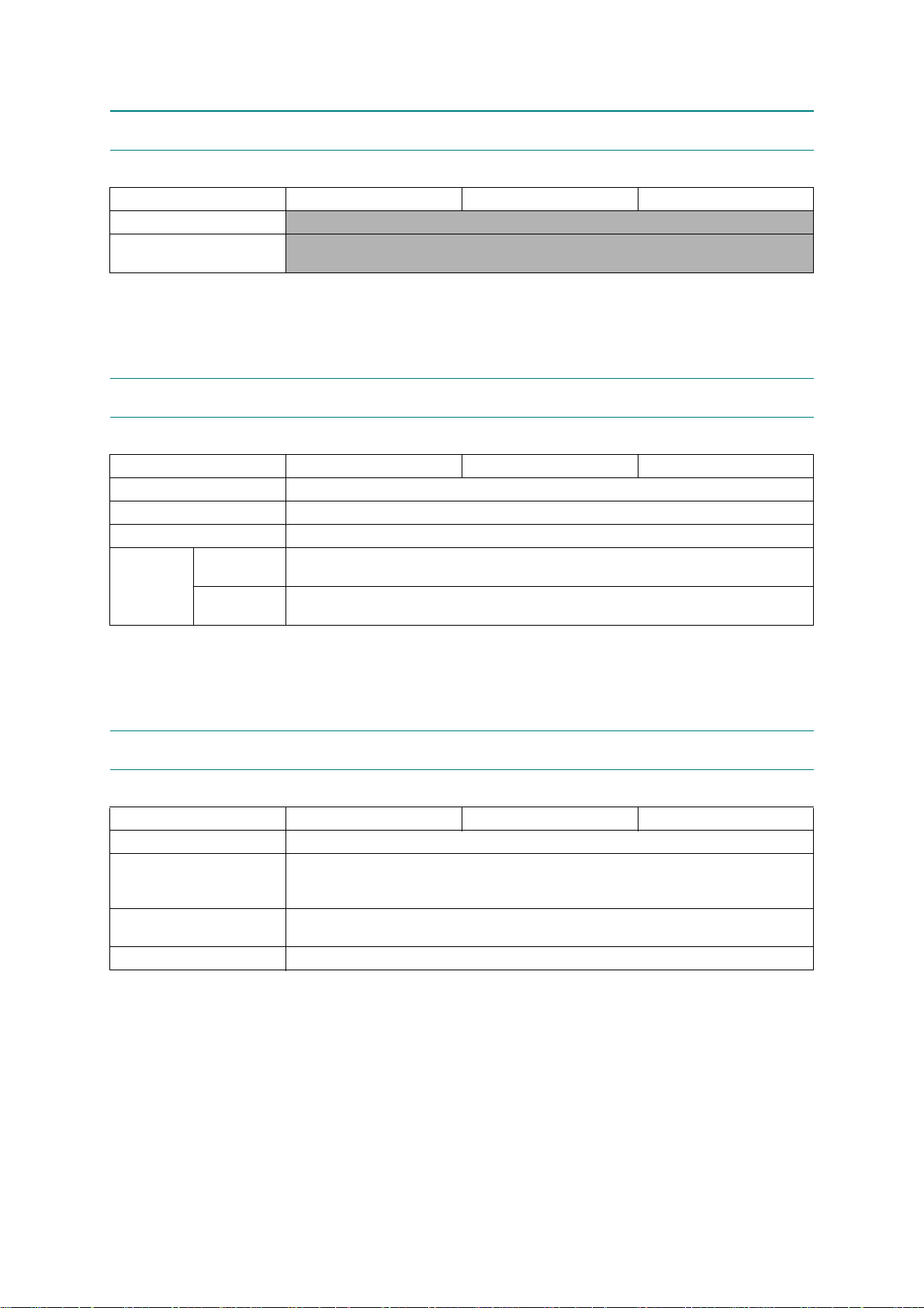
The table below shows the functional comparison between the models covered by this manual.
Model MFC-J6510DW MFC-J6710DW MFC-J6910DW
Touch panel −−√
Lower tray (Paper tray #2) −√√
Duplex scan −−Up to LTR/LGL/A4
Confidential
Page 4

TABLE OF CONTENTS
REGULATION....................................................................................................................... viii
SAFETY INFORMATION........................................................................................................ xi
CHAPTER 1 SPECIFICATIONS..................................... .. .. .. .. ............................................1-1
1.1 GENERAL ....................................................................................................................1-1
1.1.1 General............................................................................................................1-1
1.1.2 Media Specifications........................................................................................1-1
1.1.3 Paper Handling.......... ......................................................................................1-2
1.1.4 LCD/Panel........................................................................................................1-2
1.1.5 Memory............................................................................................................1-2
1.1.6 Interface...........................................................................................................1-3
1.1.7 Others..............................................................................................................1-3
1.2 TELEPHONE................................................................................................................ 1-4
1.3 FAX...............................................................................................................................1-4
1.4 PRINTER ......................................................................................................................1-4
1.5 COPY............................................................................................................................1-5
1.6 SCANNER....................................................................................................................1-5
1.7 SOFTWARE .................................................................................................................1-5
1.8 NETWORK ...................................................................................................................1-6
1.8.1 Network............................................................................................................1-6
1.8.2 Wired................................................................................................................1-6
1.8.3 Wireless...........................................................................................................1-6
1.9 SUPPLIES/OPTIONS...................................................................................................1-7
1.10 SERVICE INFORMATION............................................................................................1-7
1.11 PAPER..........................................................................................................................1-8
1.11.1 Paper Specifications ........................................................................................1-8
1.11.2 Printable Area................................................................................................1-11
CHAPTER 2 ERROR INDICATION AND TROUBLESHOOTING...................................... 2-1
2.1 INTRODUCTION ..........................................................................................................2-1
2.1.1 Precautions......................................................................................................2-1
2.1.2 Initia l Ch e ck ...... .. .................. ................. .................. .. .................. ................. ... 2-2
i
Confidential
Page 5

2.2 OVERVIEW...................................................................................................................2-3
2.2.1 Cross-section Drawings and Components.......................................................2-3
2.2.2 Paper Path for Documents and Recording Paper............................................2-4
2.2.3 Parts Names and Functions....................................................................... ......2-5
2.2.4 Block Diagram..................................................................................................2-7
2.2.5 Components.....................................................................................................2-8
2.3 ERROR INDICATION...................................................................................................2-9
2.3.1 Erro r C o des......... .. .................. ................. .................. .. .................. ..................2-9
2.3.2 Error Messages..............................................................................................2-13
2.3.3 Communications Error Codes........................................................................2-16
2.3.4 Stat us Mo n itor Errors....................... ................. .................. .................. .. .......2-20
2.4 TROUBLESHOOTING ...............................................................................................2-22
2.4.1 Erro r C a us e and S olu tions.......... .. .................. .................. .. .................. .........2-22
2.4.2 Paper Feeding Problems............. ..................................................................2-61
2.4.2.1 No paper feeding....................................................................... .............2-61
2.4.2.2 Double feeding .......................................................................................2-62
2.4.2.3 Recording paper jam............................................... ...............................2-63
2.4.2.4 Stains on recording paper ......................................................................2-67
2.4.3 Print-image Problems ............ ........................................................................2- 68
2.4.3.1 Defective images....................................................................................2-68
2.4.3.2 Troubleshooting from image defect........................................................2-69
2.4.4 Soft w a re -r e la t ed P ro b le ms ..... .. .................. .. ................. .................. ..............2-80
2.4.4.1 Cannot print data....................................................................................2-80
2.4.5 Netwo rk Problems . .................. ................. .................. .. .................. ................2-81
2.4.5.1 Cannot make a print through network connection................. .................2-81
2.4.6 Document Feeding Problems ........................................................................2-82
2.4.6.1 Cannot feed documents .........................................................................2-82
2.4.6.2 Document double feeding.......................................................................2-82
2.4.6.3 Document jam ........................................................................................2-83
2.4.6.4 Wrinkles on documents..........................................................................2-84
2.4.6.5 Cannot detect the document size correctly ............................................2-84
2.4.7 Scanned-image Problems................... .. ...................................... .. .................2-85
2.4.7.1 Defective images....................................................................................2-85
2.4.7.2 Troubleshooting from image defect........................................................2-85
2.4.8 Control Panel Problems.................................................................... .............2-89
2.4.8.1 LCD shows nothing ................................................................................2-89
ii
Confidential
Page 6

2.4.8.2 Control panel inoperative.................................................. ......................2-89
2.4.8.3 Lamps on the control panel does not light..............................................2-90
2.4.8.4 Touch panel inoperative (For models with touch panel).........................2-90
2.4.9 Fax P ro b le ms.............................. .................. ................. ... ................. ............2-91
2.4.9.1 No faxes can be sent..............................................................................2-91
2.4.9.2 Speed dialing or one-touch dialing will not work.....................................2-91
2.4.9.3 No faxes can be received.......................................................................2-92
2.4.9.4 The ringer does not sound......................................................................2-92
2.4.9.5 In on-hook dialing, the speaker does not sound.......................... ...........2-92
2.4.9.6 Dial does not switch between tone and pulse ........................................2-93
2.4.9.7 A communications error occurs..............................................................2-93
2.4.9.8 Receive mode cannot be changed.........................................................2-93
2.4.9.9 Caller ID not displayed ...........................................................................2-93
2.4.10 Other Problems..............................................................................................2-94
2.4.10.1 The machine cannot be powered on or nothing appears on the LCD....2-94
2.4.10.2 When the power is on, the scanner crackles..........................................2-94
2.4.10.3 Memory card/PictBridge does not function.............................................2-94
2.4.10.4 Memory err or s ................... .................. ................. .................. .. ..............2-95
2.4.10.5 Paper tray set does not work..................................................................2-95
CHAPTER 3 DISASSEMBLY AND ASSEMBLY ...............................................................3-1
3.1 SAFETY PRECAUTIONS AND HANDLING NOTES ...................... .. .. ........................3-1
3.2 PACKING .....................................................................................................................3-3
3.3 SCREW CATALOGUE.................................................................................................3-4
3.4 SCREW TORQUE LIST ............................................................................................... 3-5
3.5 LUBRICATION.............................................................................................................3-6
3.6 OVERVIEW OF GE A R S.. .................. ................. .. .................. .................. ................. . 3-13
3.7 HARNESS ROUTING.................... .. .......................................................... .. .. .. ...........3-14
3.8 DISASSEMBLY FLOW ..............................................................................................3-31
3.9 DISASSEMBLY PROCEDURE..................................................................................3-33
3.9.1 Preparation ....................................................................................................3-33
3.9.2 Head/Carriage Unit ........................................................................................3- 3 7
3.9.3 Scanner Cover (Scanner Unit) and Scanner Cover Support.........................3-50
3.9.4 Manual Feed Slot Cover and ADF & Document Cover ASSY.......................3-55
3.9.5 Disassembly of ADF & Document Cover ASSY ............................................3-58
iii
Confidential
Page 7

3.9.6 Control Panel ASSY.......................................................................................3-81
3.9.7 Disassembly of Control Panel ASSY.............................................................3-82
3.9.8 Backup Battery, Speaker and Upper Cover...................................................3-87
3.9.9 Ink Cartridge Cover, Front Cover, Wireless LAN PCB and Media Module
Cover .............................................................................................................3-91
3.9.10 Main PCB.......................................................................................................3-93
3.9.11 LT Cover*, T2 Paper Pull-in Roller ASSY, and Jam Clear Cover..................3-98
3.9.12 MJ/PS Shield Unit (MJ PCB and Power Supply PCB).................................3-100
3.9.13 CR Encoder Strip and its Guard Film...........................................................3-105
3.9.14 Carriage PCB ASSY, Ink Refill ASSY and Ink Cartridge Detection
Sensor PCB.................................................................................................3-107
3.9.15 Ink Absorber Box, Ink Absorber Felt, and PF Encoder Disk........................3-113
3.9.16 Duplex-printing Related Components..........................................................3-115
3.9.17 Engine Unit, Flashing Box and Ink Cartridge Cover Switch.........................3-117
3.9.18 Components on the Engine Unit
(Earth spring, Maintenance unit, Carriage motor, CR support chassis,
Star wheel holder, Intermediate roller, Inner paper guide, Switchback
paper sensor PCB ASSY, Platen, DX chute roller holder ASSYs,
Inner chute ASSY, Registration sensor PCB ASSY and actuator,
PF encoder/PF sensor harness unit and actuator, PF encoder disk,
Paper feed motor, T1 paper pull-in roller ASSY) .........................................3-121
3.9.19 Paper Tray #1..............................................................................................3-134
3.9.20 Paper Tray #2..............................................................................................3-135
CHAPTER 4 ADJUSTMENTS AND UPDATING OF SETTINGS, REQUIRED AFTER
PARTS REPLACEMENT...............................................................................4-1
4.1 IF YOU REPLACE THE HEAD/CARRIAGE UNIT OR ENGINE UNIT........................4-1
[ 1 ] Update the head property data stored in the EEPROM on the main PCB*........4-2
[ 2 ] Clean the new head/carriage unit (Function code 76)........................................4-5
[ 3 ] Print out a nozzle test pattern (Function code 09)..............................................4-6
[ 4 ] Adjust the inclination of the head/carriage unit...................................................4-7
[ 5 ] Update the paper feeding correction value (Function code 58)........................4-10
[ 6 ] Adjust the height of the platen..........................................................................4-17
[ 7 ] Align vertical print lines in monochrome (Function code 65)............................4-19
[ 8 ] Adjust margins in borderless printing (Function code 66).................................4-21
[ 9 ] Create head calibration data and write it into flash ROM
(Function code 02)............................................................................................4-24
[ 10 ] Print out a total quality check pattern................................................................4-27
[ 11 ] Switch back to standby.....................................................................................4-29
[ 12 ] Replace the ink cartridges with the protective part...........................................4-29
iv
Confidential
Page 8

[ 13 ] Obtain machine information at the user site (Instruction to the end user)........4-29
4.2 IF YOU REPLACE THE MAIN PCB...........................................................................4-30
[ 1 ] Load update programs/data..............................................................................4-31
[ 2 ] Customize the EEPROM on the main PCB (Function code 74).......................4-36
[ 3 ] Initialize the EEPROM on the main PCB (Function code 01)...........................4-36
[ 4 ] Load local programs.........................................................................................4-36
[ 5 ] Restore machine information (Function code 46).............................................4-36
[ 6 ] Restore head calibration data (Function code 68)............................................4-36
[ 7 ] Check the sensor operation (Function code 32)...............................................4-36
[ 8 ] Set an ID code (change the serial number) and update the head property
data...................................................................................................................4-37
[ 9 ] Acquire white level data and set CIS scanner area (Function code 55)...........4-39
[ 10 ] Update the paper feeding correction value (Function code 58)........................4-39
[ 11 ] Align vertical print lines (Function code 65)......................................................4-39
[ 12 ] Adjust margins in borderless printing (Function code 66).................................4-39
[ 13 ] Create head calibration data and write it into flash ROM (Function code 02)..4-39
[ 14 ] Print out an ADF copy chart and make a copy of that chart in ADF scanning..4-39
[ 15 ] Print out a total quality check pattern................................................................4-39
[ 16 ] Adjust the touch panel (Function code 78) (For models with touch panel).......4-39
[ 17 ] Switch back to standby.....................................................................................4-39
4.3 IF YOU REPLACE THE ADF OR ADF-RELATED PARTS.......................................4-40
[ 1 ] Print out an ADF copy chart and make a copy of that chart in ADF scanning..4-40
4.4 IF YOU REPLACE THE INK ABSORBER BOX OR FLUSHING BOX .....................4-43
[ 1 ] Reset each of the purge and flushing counts...................................................4-43
4.5 IF YOU REPLACE THE CONTROL PANEL ASSY, CONTROL PANEL PCB OR
LCD UNIT...................................................................................................................4-43
[ 1 ] Adjust the touch panel (Function code 78) (For models with touch panel).......4-43
[ 2 ] Check LCD operation (Function code 12) ........................................................4-43
[ 3 ] Check the operation of the control panel PCB (Function code 13)...................4-43
4.6 IF YOU REPLACE THE FB UNIT* OR SCANNER COVER (SCANNER UNIT) .......4-44
[ 1 ] Acquire white level data and set CIS scanner area (Function code 55)...........4-44
[ 2 ] Print out an ADF copy chart and make a copy of that chart in ADF scanning
(For models with ADF)......................................................................................4-44
v
Confidential
Page 9

CHAPTER 5 SERVICE FUNCTIONS .................................................................................5-1
5.1 MAINTENANCE MODE................................................................................................5-1
5.1.1 How to Enter the End User-accessible Maintenance Mode.............................5-1
5.1.2 How to Enter the Maintenance Mode Exclusive to Service Personnel............5-2
5.1.3 List of Maintenance-mode Functions...............................................................5-4
5.1.4 Detailed Description of Maintenance-mode Functions ....................................5-5
5.1.4.1 EEPROM Parameter Initialization (Function code 01, 91) .......................5-5
5.1.4.2 Creating of Head Calibration Data and Writing it into Flash ROM
(Function code 02)....................................................................................5-6
5.1.4.3 Printout of Scanning Compensation Data (Function code 05) .................5-9
5.1.4.4 ADF Performance Test (Function code 08)............................................5-11
5.1.4.5 Printout of Nozzle Test Pattern (Function code 09)................................5-12
5.1.4.6 Firmware Switch Setting and Printout (Function codes 10 and 11)
(User-accessible)....................................................................................5-14
5.1.4.7 Operational Check of LCD (Function code 12) (User-accessible)..........5-17
5.1.4.8 Operational Check of Control Panel PCB (Function code 13)................5-18
5.1.4.9 Updating of Firmware Using an External Memory (Function code 28)...5-19
5.1.4.10 Sensor Operational Check (Function code 32)......................................5-20
5.1.4.11 Backup of Machine Information (Function code 46) (User-accessible)..5-22
5.1.4.12 Setting of Country/Language (Function code 52) (User-accessible)......5-24
5.1.4.13 Transfer of Received FAX Data and Log Information
(Function code 53) (User-accessible).....................................................5-25
5.1.4.14 Fine Adjustment of Scanning Position (Function code 54).....................5-28
5.1.4.15 Acquisition of White & Black Level Data and CIS Scanner Area Setting
(Function code 55)..................................................................................5-29
5.1.4.16 Updating of Paper Feeding Correction Value (Function code 58)..........5-30
5.1.4.17 Checking of CIS Travel (Function code 59)............................................5-37
5.1.4.18 Printout of PRN/JPEG Files in Memory Card (Function code 61)..........5-38
5.1.4.19 Travel Check of the Head/Carriage Unit and Initial Setup Mode
(Function code 63)..................................................................................5-40
5.1.4.20 Alignment of Vertical Print Lines in Monochrome (Function code 65)....5-41
5.1.4.21 Margin Adjustment in Borderless Printing (Function code 66)
(User-accessible)....................................................................................5-43
5.1.4.22 Updating of Head Property Data and Backup/Restoration of
Head Calibration Data (Function code 68).............................................5-46
5.1.4.23 Traveling Speed Check of Head/Carriage Unit (Function code 69) .......5-48
5.1.4.24 Cleaning of Leveler Roller (LR) ASSY (Function code 70).....................5-49
5.1.4.25 EEPROM Customizing (Function code 74)............................................5-50
vi
Confidential
Page 10

5.1.4.26 Travel of Head/Carriage Unit (for removing paper particles and
dust accumulated on the maintenance unit) (Function code 75)
(User-accessible)....................................................................................5-53
5.1.4.27 Purge Operation (Function code 76) (User-accessible) .........................5-54
5.1.4.28 Print of the Equipment’s Log (Function code 77) ...................................5-57
5.1.4.29 Adjustment of Touch Panel (Function code 78) ............... ......................5-60
5.1.4.30 Display of the Equipment's Log (Function code 80) (User-accessible)..5-62
5.1.4.31 Equipment Error Code Indication (Function code 82)
(User-accessible)....................................................................................5-67
5.1.4.32 Output of Transmission Log to the Telephone Line (Function code 87)
(User-accessible)....................................................................................5-67
5.1.4.33 Assurance Mode Switch Setting (Function code 88) (User-accessible).5-68
5.2 OTHER SERVICE FUNCTIONS.................................................................................5-75
5.2.1 Cancellation of the Pin TX Lock Mode (Not applicable to Japanese and
U.S.A. models)...............................................................................................5-75
5.2.2 Displaying the Firmware Version ...................................................................5-75
5.2.3 Travel of Head/Carriage Unit......... ................................................................5-75
CHAPTER 6 Circuit Diagrams and Wiring Diagrams .....................................................6-1
APPENDIX 1 SERIAL NUMBERING SYSTEM.................................................... ...... App. 1-1
APPENDIX 2 DEL E T ION OF USER SETTING INF ORMATION................................App. 2-1
A2.1 Deleting User Setting Info from the Machine........................................App. 2-1
APPENDIX 3 INSTALLING THE MAINTENANCE PRINTER DRIVER .....................App. 3-1
vii
Confidential
Page 11
REGULATION
Federal Communications Commission (FCC) Declaration of Conformity (USA
only)
viii
Confidential
Page 12

Industry Canada Compliance Statement (Canada only)
This Class B digital apparatus complies with Canadian ICES–003.
Cet appareil numérique de la classe B est conforme à la norme NMB–003 du Canada.
Operation is subject to the following two conditions:
(1) this device may not cause interference, and (2) this device must accept any interference,
including interference that may cause undesired operation of this device.
L'utilisation de ce dispositif est autorisée seulement aux conditions suivantes:
(1) il ne doit pas produire de brouillage et (2) l'utilisateur du dispositif doit être prêt à accepter
tout brouillage radioélectrique reçu, même si ce brouillage est susceptible de compromettre le
fonctionnement du dispositif.
EQUIPMENT ATTACHMENT LIMITATIONS (Canada only)
NOTICE
This product meets the applicable Industry Canada technical specifications.
NOTICE
The Ringer Equivalence Number is an indication of the maximum number of devices allowed to
be connected to a telephone interface. The termination on an interface may consist of any
combination of devices subject only to the requirement that the sum of the RENs of all the
devices does not exceed five.
LAN connection
Declaration of Conformity (Europe only)
We, Brother Industries, Ltd.
15-1, Naeshiro-cho, Mizuho-ku, Nagoya 467-8561 Japan
declare that this product is in compliance with the essential requirements of Directives 1999/5/
EC and 2005/32/EC.
The Declaration of Conformity (DoC) is on our Website.
Please go to http://solutions.brother.com/
-> choose region (eg. Europe)
-> choose country
-> choose your model
-> choose "Manuals"
-> choose Declaration of Conformity (Select Language when required.)
ix
Confidential
Page 13
Wiring information (U.K. only)
If you need to replace the plug fuse, fit a fuse that is approved by ASTA to BS1362 with the
same rating as the original fuse. Always replace the fuse cover. Never use a plug that does not
have a cover. If in any doubt, call a qualified electrician.
Warning - This machine must be earthed.
The wires in the mains lead are colored in line with the following code:
- Green and Yellow: Earth
- Blue: Neutral
- Brown: Live
Radio interference
This product complies with EN55022 (CISPR Publication 22)/Class B. When connecting the
machine to a computer, ensure that you use a USB cable which does not exceed 2 m in length.
Recycling information in accordance with the WEEE (2002/96/EC) and Battery
(2006/66/EC) Directives
Product mark Battery mark
European Union only
The product/battery is marked with one of the above recycling symbols. It indicates that at the
end of the life of the product/battery, you should dispose of it separately at an appropriate
collection point and not place it in the normal domestic waste stream.
For products with user replaceable batteries please refer to the users guide for replacement
instructions.
International ENERGY STAR® Qualification Statement
The purpose of the International ENERGY STAR® Program is to promote the development and
popularization of energy-efficient equipment.
As an ENERGY STAR
the ENERGY STAR
®
Partner, Brother Industries, Ltd. has determined that this product meets
®
specifications for energy efficiency.
x
Confidential
Page 14

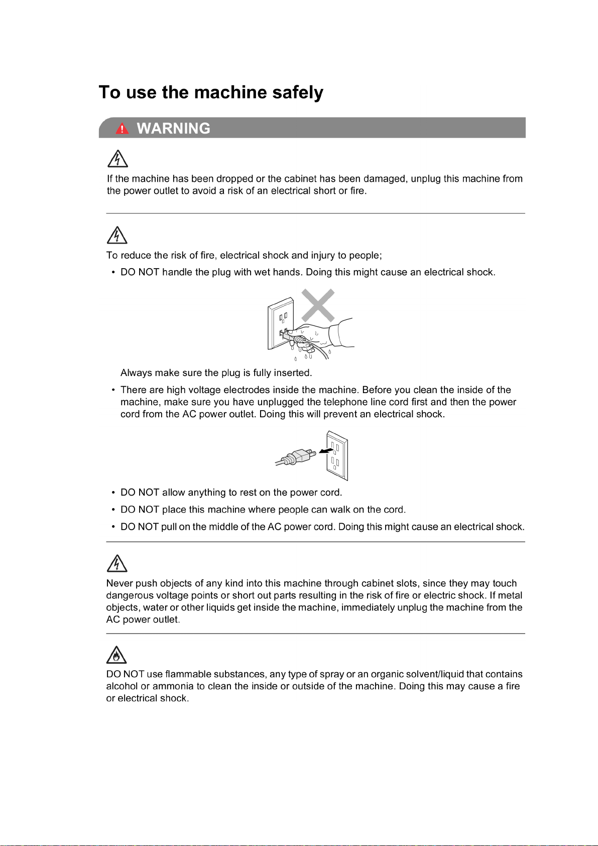
SAFETY INFORMATION
WARNING
CAUTION
WARNING
WARNING indicates a potentially hazardous situation which, if not avoided, could result in
death or serious injuries.
CAUTION
CAUTION
or moderate injuries.
indicates a potentially hazardous situation which, if not avoided, may result in minor
IMPORTANT
IMPORTANT
damage to property or loss of product functionality.
Follow all warnings and instructions marked on the machine.
indicate a potentially hazardous situation which, if not avoided, may result in
Notes tell you how you should respond to a situation that may arise or give tips about
how the operation works with other features.
Electrical Hazard icons alert you to possible electrical shock.
Improper Setup icons alert you to devices and operations that are not compatible with
the machine.
Fire Hazard icons alert you to the possibility of fire.
xi
Confidential
Page 15
xii
Confidential
Page 16
xiii
Confidential
Page 17

xiv
Confidential
Page 18

xv
Confidential
Page 19

xvi
Confidential
Page 20
CHAPTER 1 SPECIFICATIONS
This chapter lists the specifications of each model, which enables you to make a comparison of
different models.
1.1 GENERAL
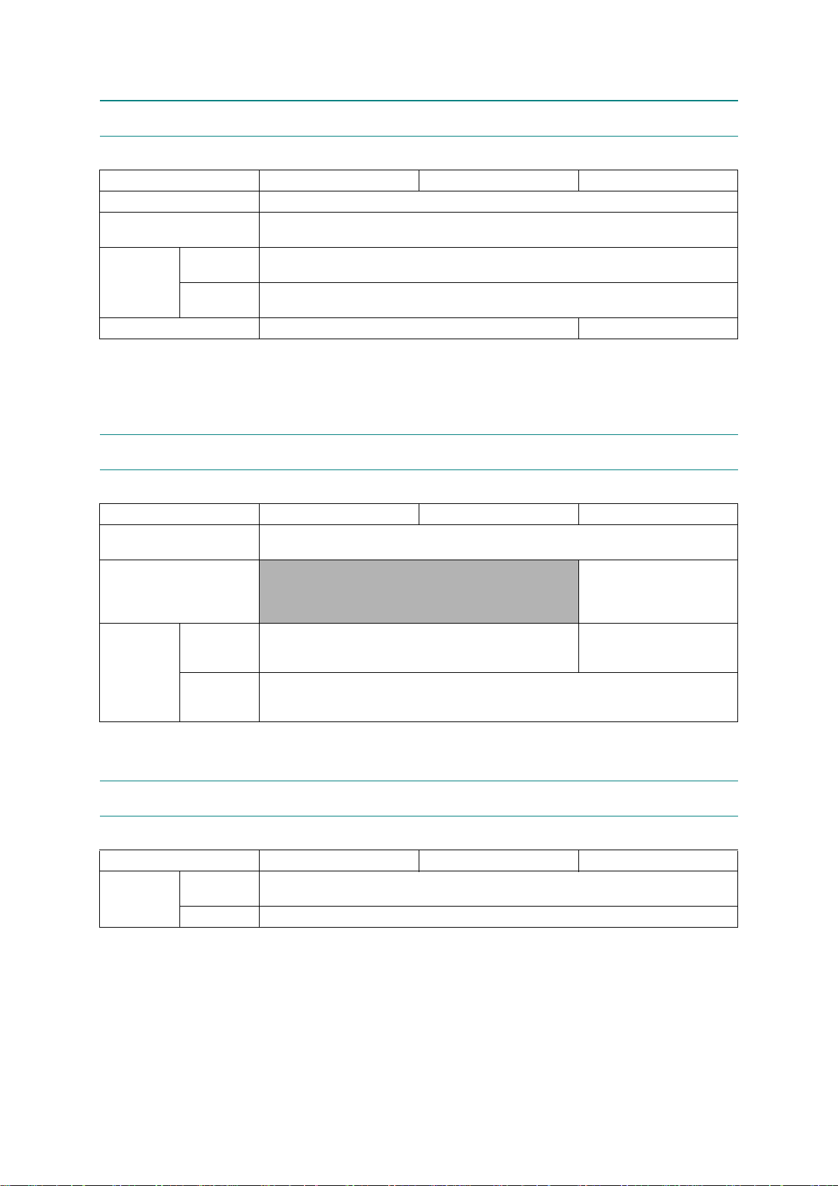
1.1.1 General
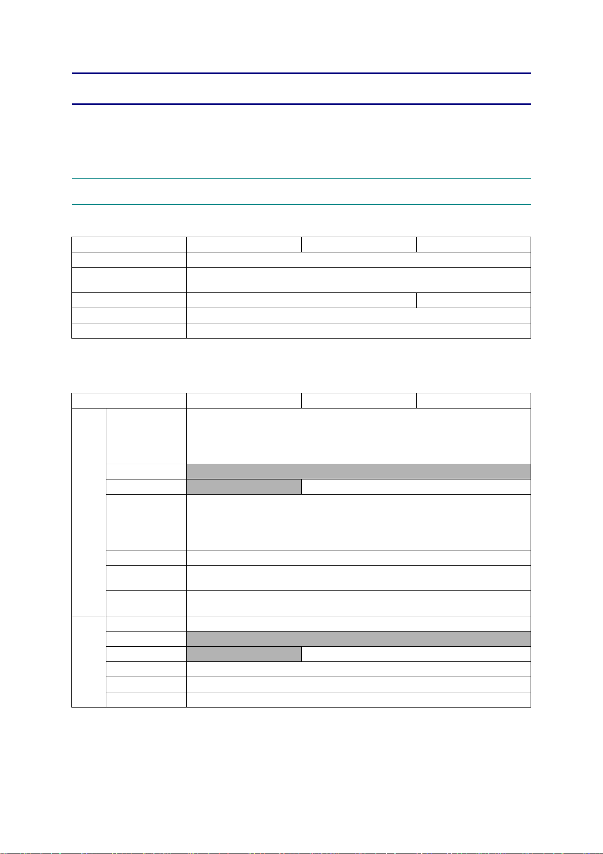
Model MFC-J6510DW MFC-J6710DW MFC-J6910DW
Print Head BH11
Minimum Droplet Size
Scanning Method CIS x 1 CIS x 2
CPU Speed RISC 192 MHz
Backup Clock Yes
1.1.2 Media Specifications
BK: 3 pl
CMY: 1.5 pl
Media
Sizes
Media
Weights
Model MFC-J6510DW MFC-J6710DW MFC-J6910DW
A3, A4, LGR, LTR, LGL, EXE, JIS B4, JIS B5, A5, A6, Photo (102 x 152 mm/4 x 6 inches),
Standard Tray
Photo Tray
Lower Tray
Manual Feed Slot
Duplex Print A3/LGR/LGL/A4/LTR/EXE/A5/A6/JIS B4/JIS B5
ADF
(width/length)
Scanner Glass
(width/length)
Standard Tray 64-220 g/m
Photo Tray
Lower Tray
Manual Feed Slot 64-285 g/m
Duplex Print 64-105 g/m
ADF 64-90 g/m
Indexcard (127 x 203 mm/5 x 8 inches), Photo-L (89 x 127 mm/3.5 x 5 inches),
Photo-2L (127 x 178 mm/5 x 7 inches), Post Card 1 (100 x 148 mm/3.9 x 5.8 inches),
Post Card 2 (Double) (148 x 200 mm/5.8 x 7.9 inches), C5 Envelope, Com-10,
DL Envelope, Monarch, JE4 Envelope
N/A
N/A JIS B5, EXE, A4/LTR, LGL, JIS B4, A3/LGR
A3, A4, LGR, LTR, LGL, EXE, JIS B4, JIS B5, A5, A6, Photo (102 x 152 mm/4 x 6 inches),
Indexcard (127 x 203 mm/5 x 8 inches), Photo-L (89 x 127 mm/3.5 x 5 inches),
Photo-2L (127 x 178 mm/5 x 7 inches), Post Card 1 (100 x 148 mm/3.9 x 5.8 inches),
Post Card 2 (Double) (148 x 200 mm/5.8 x 7.9 inches), C5 Envelope, Com-10,
148/148 mm to 297/431.8 mm (5.8/5.8 inches to 11.7/17.0 inches)
N/A 64-105 g/m2 (17-28 lb.)
DL Envelope, Monarch, JE4 Envelope
Up to 297/431.8 mm (Up to 11.7/17.0 inches)
2
(17-58 lb.)
N/A
2
(17-76 lb.)
2
(17-28 lb.)
2
(17-24 lb.)
1-1
Confidential
Page 21
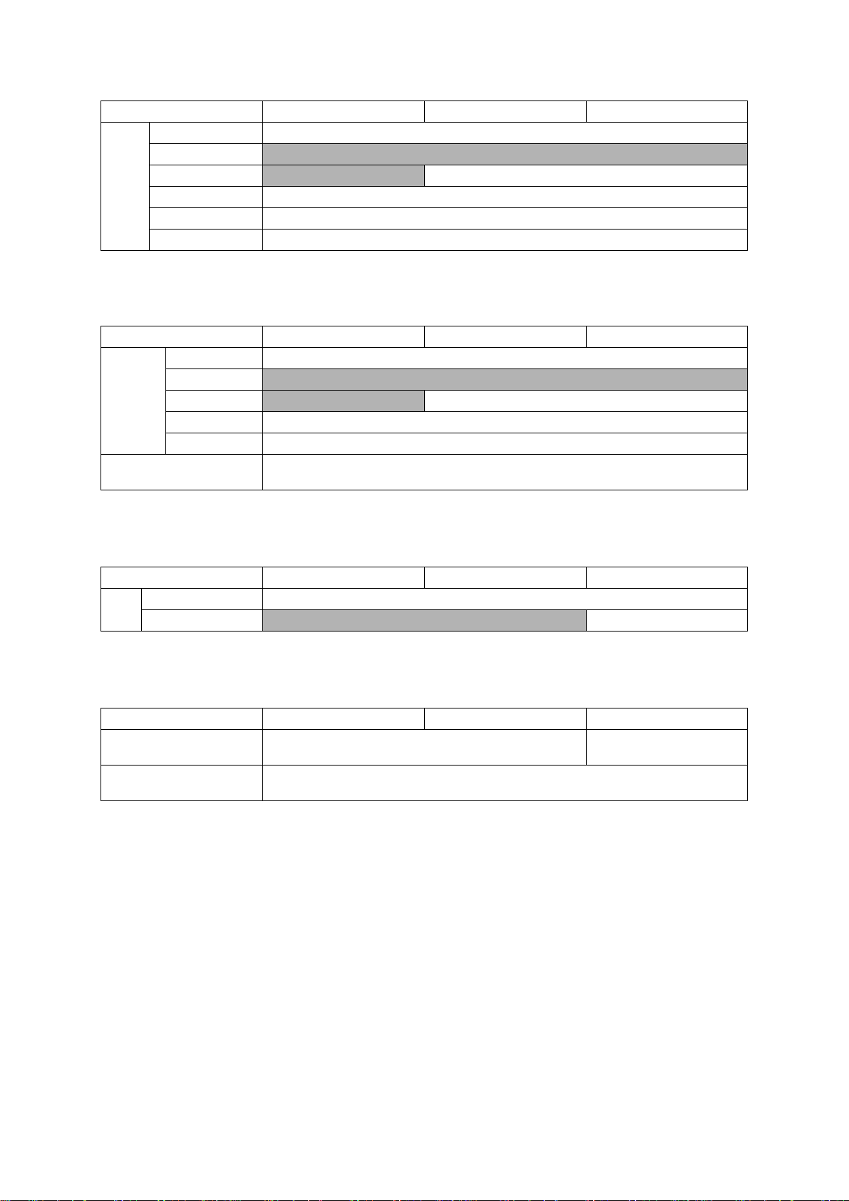
Model MFC-J6510DW MFC-J6710DW MFC-J6910DW
Standard Tray Plain, Inkjet, Glossy (cast/resin coated), Transparency
Photo Tray
Media
Types
Lower Tray
Manual Feed Slot Plain, Inkjet, Glossy (cast/resin coated), Transparency, Envelope, Label
Duplex Print Plain
ADF Plain
1.1.3 Paper Handling
Model MFC-J6510DW MFC-J6710DW MFC-J6910DW
Standard Tray 250 (80 g/m
Paper Input
(sheets)
Output Paper Capacity
(sheets)
Photo Tray
Lower Tray
Manual Feed Slot 1 (Plain: 120 g/m
ADF 35 (90 g/m
N/A
N/A Plain
2
)
N/A
N/A 250 (80 g/m2)
2
, Glossy: 0.28 mm)
2
)
50
1.1.4 LCD/Panel
Model MFC-J6510DW MFC-J6710DW MFC-J6910DW
Type & Size 3.3-inch Wide TFT Color LCD
LCD
Touch-Screen
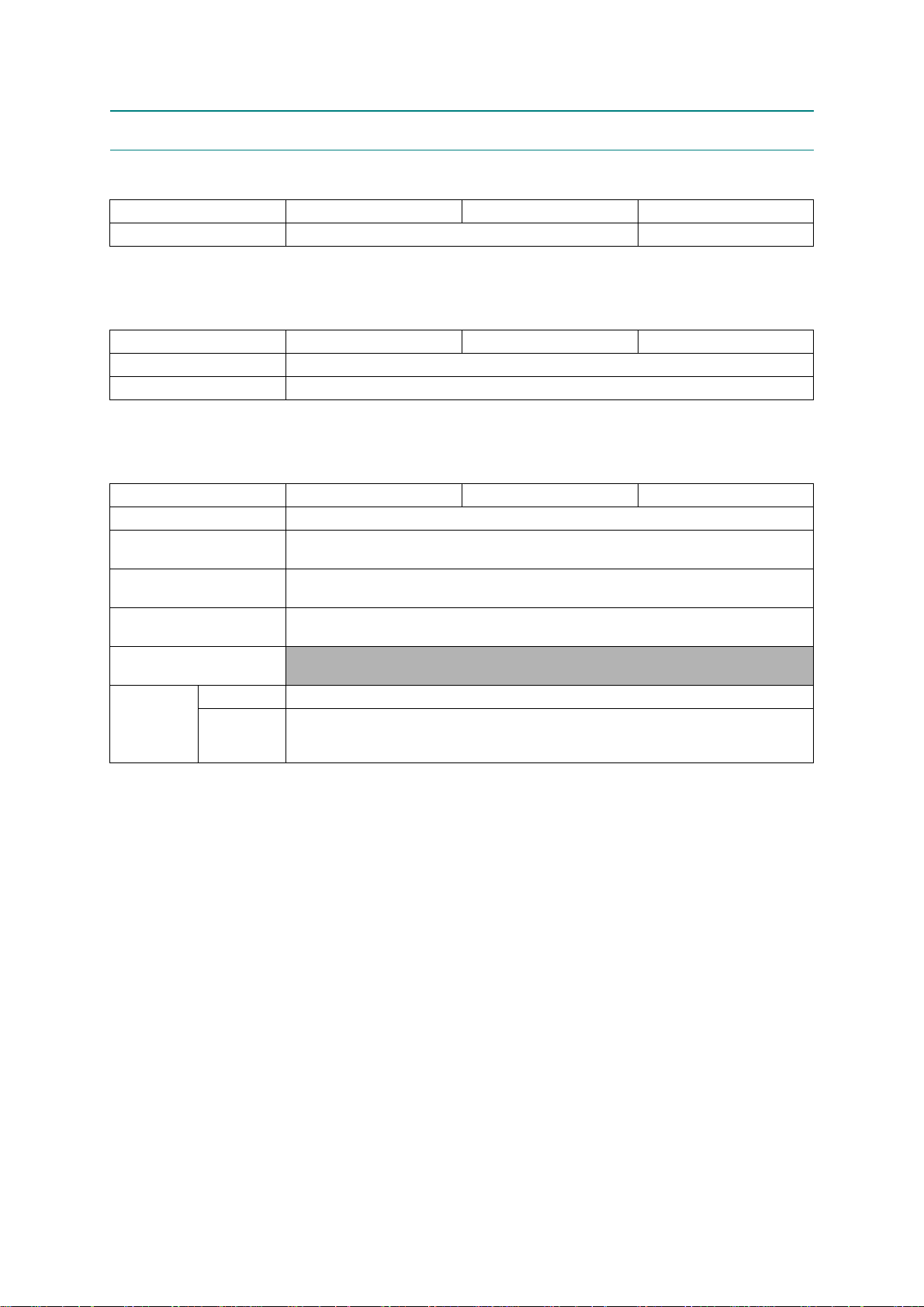
1.1.5 Memory
Model MFC-J6510DW MFC-J6710DW MFC-J6910DW
Memory Capacity
(physical: megabytes)
Memory Backup
(with battery, 24 hours)
N/A Yes
64 MB 192 MB
Yes
1-2
Confidential
Page 22
1.1.6 Interface
Model MFC-J6510DW MFC-J6710DW MFC-J6910DW
Host Interface USB 2.0 Hi-Speed
LAN Yes
Wireless LAN Yes
Bluetooth
IrSimple
PictBridge Yes
USB Flash Memory Yes
"Memory Stick"
"Memory Stick Pro"
"Memory Stick Duo"
Acceptable Media Cards
"Memory Stick Duo Pro"
"Secure Digital"
"Secure Digital High Capacity"
"Multi Media Card"
N/A
N/A
1.1.7 Others
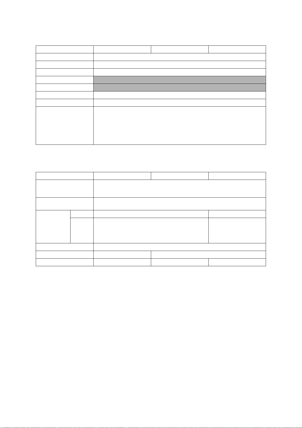
Model MFC-J6510DW MFC-J6710DW MFC-J6910DW
Operating Environment
Temperature (Best Print
Quality)
Operating Environment
Humidity (Best Print Quality)
Power
Consumption
Approx.
(Copying
Standby/Sleep/
OFF mode)
Machine Noise (Operating) 50 dBA (Maximum)
Machine Dimensions 540 x 489 x 257 mm 540 x 489 x 331 mm
Machine Weight 15.8 kg (34.8 lb.) 18.2 kg (40.1 lb.) 18.5 kg (40.8 lb.)
*2
U.S.A. 26/7/3.5/0.3 W 28/8/4/0.3 W
*1
Europe/
/
*3
Asia
Oceania
/
10-35 (20-33) degrees centigrade
20-80 (20-80) %
26/7.5/4/0.3 W 28/8.5/4/0.3 W
*1 Measured when the machine is connected to a USB interface.
*2 Measured under the following conditions:
- ADF scanning
- Simplex printing/scanning (on duplex scann i n g mo de l s )
- Resolution: Standard
- Document: ISO/IEC 24712
*3 Except Taiwan
1-3
Confidential
Page 23
1.2 TELEPHONE
Model MFC-J6510DW MFC-J6710DW MFC-J6910DW
Handset
Digital Cordless Phone
(Cordless Handset)
N/A
N/A
1.3 FAX
Model MFC-J6510DW MFC-J6710DW MFC-J6910DW
Modem Speed 33,600 bps
Transmission Speed Approx. 3 seconds (Brother #1, MMR)
ITU-T Group Super G3
Color FAX
Document
(Send/Receive)
Memory
(Send/Receive)
Yes/Yes (ITU-T color FAX)
No/No (ITU-T color FAX)
1.4 PRINTER
Model MFC-J6510DW MFC-J6710DW MFC-J6910DW
Print Speed (mono/color)
Print Speed ESAT
(mono/color)
(based on ISO/IEC 24734)
Resolution
(horizontal x vertical)
Auto Duplex Print Yes (up to A3)
Maximum 35/27 ppm (Simplex Print)
12/10 ipm (Normal Mode: 600 x 300 dpi)
Up to 1,200 x 6,000 dpi
1-4
Confidential
Page 24
1.5 COPY
Model MFC-J6510DW MFC-J6710DW MFC-J6910DW
Copy Speed (A4/LTR)
Copy Speed ESAT
(based on ISO/IEC 24735)
Resolution
(horizontal x
vertical)
Duplex Copy Yes (w/o Duplex Scan) Yes
Mono
Color
Maximum 23/20 cpm (Simplex Copy)
6/6 ipm (Normal Mode: 600 x 600 dpi)
Print: Maximum 1,200 x 1,200 dpi
Scan: Maximum 1,200 x 1,200 dpi
Print: Maximum 1,200 x 1,200 dpi
Scan: Maximum 1,200 x 1,200 dpi
1.6 SCANNER
Model MFC-J6510DW MFC-J6710DW MFC-J6910DW
Scan Speed
(Mono/Color) *@100 dpi
Scan Speed (Duplex)
(Mono/Color) *@100 dpi
Resolution
(horizontal x
vertical)
Optical
Interpolated
(For Win XP/Vista/7, up to 19,200 x 19,200 dpi with Scanner Utility)
A4: Mono 3.49 seconds, Color 4.71 seconds
Letter: Mono 3.29 seconds, Color 4.43 seconds
N/A
2,400 x 2,400 dpi (FB)
2,400 x 1,200 dpi (SX ADF)
TWAIN: Maximum 19,200 x 19,200 dpi
WIA: Maximum 1,200 x 1,200 dpi
A4: Mono 4.68 seconds,
Color 6.32 seconds
Letter: Mono 4.48 seconds,
Color 6.04 seconds
2,400 x 2,400 dpi (FB)
2,400 x 1,200 dpi (SX ADF)
600 x 600 dpi (DX ADF)
1.7 SOFTWARE
Model MFC-J6510DW MFC-J6710DW MFC-J6910DW
Support OS
Version
Windows
Macintosh Mac OS X 10.4.11, 10.5.x, 10.6.x
2000/XP x64/Vista/7
Server 2003/2003 x64/2003 R2/2003 R2 x64/2008/2008 R2
1-5
Confidential
Page 25
1.8 NETWORK
1.8.1 Network
Model MFC-J6510DW MFC-J6710DW MFC-J6910DW
Internet FAX (Firmware) Yes (Download) Yes
1.8.2 Wired
Model MFC-J6510DW MFC-J6710DW MFC-J6910DW
Model Name (Ethernet) NC-230h
Network Connection (Ethernet) Y es (for Wireless LAN & WIRED at once) (in LAN Menu)
1.8.3 Wireless
Model MFC-J6510DW MFC-J6710DW MFC-J6910DW
Model Name (Wireless) NC-240w
Network Connection
(Wireless)
Wireless Security
WiFi Certification
WCN
(Windows Connect Now)
AOSS Yes
Setup Support
Utility
WPS (WiFi
Protected
Setup)
SSID (32 chr), WEP 64/128 bit, WPA-PSK (TKIP: AES), WPA2-PSK (AES)
IEEE 802.11 b/g/n
(Russia IEEE 802.11 b/g)
**NO LEAP**
WiFi b, g and n
(Russia WiFi b and g)
N/A
Yes
1-6
Confidential
Page 26

1.9 SUPPLIES/OPTIONS
Model MFC-J6510DW MFC-J6710DW MFC-J6910DW
Bundled Ink Cartridge Type High yield
Bundled Cartridges Approx. 390/390 (BK/CL)
Ink
Cartridge
Yield
(@ISO
pattern/
normal)
Supply Standard
Cartridges
Supply High Yield
Cartridges
Supply Super High
Yield Cartridges
N/A
Approx. 600/600 (BK/CL)
Approx. 2,400/1,200 (BK/CL)
1.10 SERVICE INFORMATION
Model MFC-J6510DW MFC-J6710DW MFC-J6910DW
Monthly Volume 5,000 pages
Machine Life 60,000 pages or 5 years
Parts Life
(Scanner unit (Scanner cover))
MTBF (Mean Time Between
Failures)
MTTR (Mean Time To Be
Repaired)
60,000 pages (Total in flat-bed and ADF scanning)
4,000 hours
30 minutes
1-7
Confidential
Page 27
1.11 PAPER
1.11.1 Paper Specifications
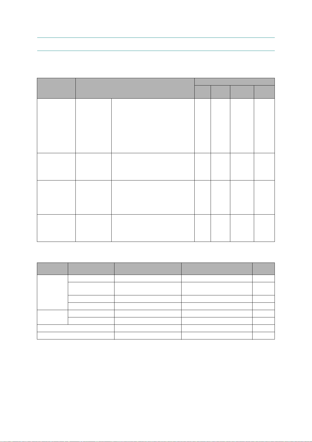
Paper type and size for each operation
Paper Type Paper Size Usage
Fax Copy Photo
Capture
Cut Sheet Ledger 279.4 x 431.8 mm (11 x 17 inches) Yes Yes Yes Yes
A3 297 x 420 mm (11.7 x 16.5 inches ) Yes Yes Yes Yes
Letter 215.9 x 279.4 mm (8 1/2 x 11 inches) Yes Yes Yes Yes
A4 210 x 297 mm (8.3 x 11.7 inches) Yes Yes Yes Yes
Legal 215.9 x 355.6 mm (8 1/2 x 14 inches) Yes Yes -- Yes
Executive 184 x 267 mm (7 1/4 x 10 1/2 inches) -- Yes -- Yes
A5 148 x 210 mm (5.8 x 8.3 inches) -- Yes -- Yes
A6 105 x 148 mm (4.1 x 5.8 inches) -- -- -- Yes
Cards Photo 10 x 15 cm (4 x 6 inches) -- Yes Yes Yes
Photo L 89 x 127 mm (3 1/2 x 5 inches) -- -- -- Yes
Photo 2L 13 x 18 cm (5 x 7 inches) -- -- Yes Yes
Index Card 127 x 203 mm (5 x 8 inches) -- -- -- Yes
Envelopes C5 Envelope 162 x 229 mm (6.4 x 9 inches) -- -- -- Yes
DL Envelope 110 x 220 mm (4.3 x 8.7 inches) -- -- -- Yes
COM-10 105 x 241 mm (4 1/8 x 9 1/2 inches) -- -- -- Yes
Monarch 98 x 191 mm (3 7/8 x 7 1/2 inches) -- -- -- Yes
JE4 Envelope 105 x 235 mm (4.1 x 9.3 inches) -- -- -- Yes
Transparencies Letter 215.9 x 279.4 mm (8 1/2 x 11 inches) -- Yes -- Yes
A4 210 x 297 mm (8.3 x 11.7 inches) -- Yes -- Yes
Legal 215.9 x 355.6 mm (8 1/2 x 14 inches) -- Yes -- Yes
A5 148 x 210 mm (5.8 x 8.3 inches) -- Yes -- Yes
Printer
Paper weight, thickness and capacity
Paper Type Weight Thickness No. of
sheets
Cut Sheet Plain Paper
(Tray #2) Plain
Paper 17 to 32 lb. (64 to 120 g/m
Inkjet Paper
Glossy Paper
*4
*4
*4
17 to 32 lb. (64 to 120 g/m2) 3 to 6 mil (0.08 to 0.15 mm) 250
2
) 3 to 6 mil (0.08 to 0.15 mm) 250
17 to 53 lb. (64 to 200 g/m2) 3 to 10 mil (0.08 to 0.25 mm) 20
Up to 58 lb. (Up to 220 g/m2) Up to 10 mil (Up to 0.25 mm) 20
Cards Photo 4 x 6 inches Up to 58 lb. (Up to 220 g/m2) Up to 10 mil (Up to 0.25 mm) 20
2
Index Card Up to 32 lb. (Up to 120 g/m
Envelopes
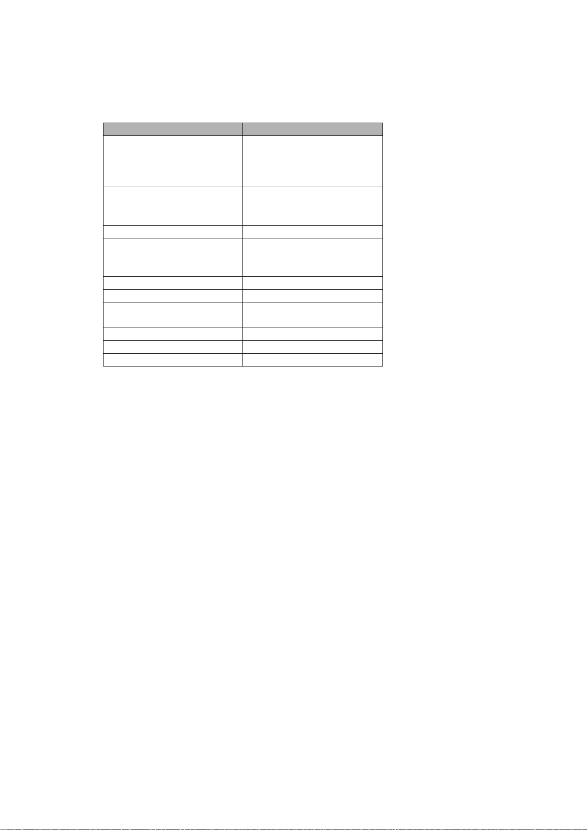
Transparencies
*1
Up to 250 sheets of plain paper 20 lb. (80 g/m2).
*2
Up to 250 sheets of plain paper 20 lb. (80 g/m2).
*3
BP71 69 lb. (260 g/m2) paper is especially designed for Brother inkjet machines.
*4
The manual feed slot can accept a sheet of paper at a time.
*4
*4
20 to 25 lb. (75 to 95 g/m2) Up to 20 mil (Up to 0.52 mm) 10
-- -- 10
) Up to 6 mil (Up to 0.15 mm) 30
*1
*2
*3
*3
1-8
Confidential
Page 28
Recommended print media
To get the best print quality, we suggest using Brother paper. (See the table below.)
We recommend using "3M Transparency Film" when you print on transparencies.
Paper Type Item
Premium Plus Glossy Photo
- Ledger BP71GLGR
- Letter BP71GLTR
- 4 x 6 inches BP71GP
Premium Glossy Photo
- Letter BP61GLL (USA only)
- 4 x 6 inches BP61GLP (USA only)
Matte Inkjet (Letter) BP60ML (USA only)
Plain Inkjet
- Ledger BP60PLGR (USA only)
- Letter BP60PL100 (USA only)
A3 Plain BP60PA3
A3 Glossy Photo BP71GA3
A3 Inkjet (Matte) BP60MA3
A4 Plain BP60PA
A4 Glossy Photo BP71GA4
A4 Inkjet (Matte) BP60MA
10 x 15 cm Glossy Photo BP71GP
Handling and using print media
Store paper in its original packaging, and keep it sealed. Keep the paper flat and away from
moisture, direct sunlight and heat.
Avoid touching the shiny (coated) side of photo paper. Load photo paper with the shiny side
facing down.
Avoid touching either side of transparencies because they absorb water and perspiration
easily, and this may cause decreased output quality. Transparencies designed for laser
printers/copiers may stain your next document. Use only transparencies recommended for
inkjet printing.
1-9
Confidential
Page 29
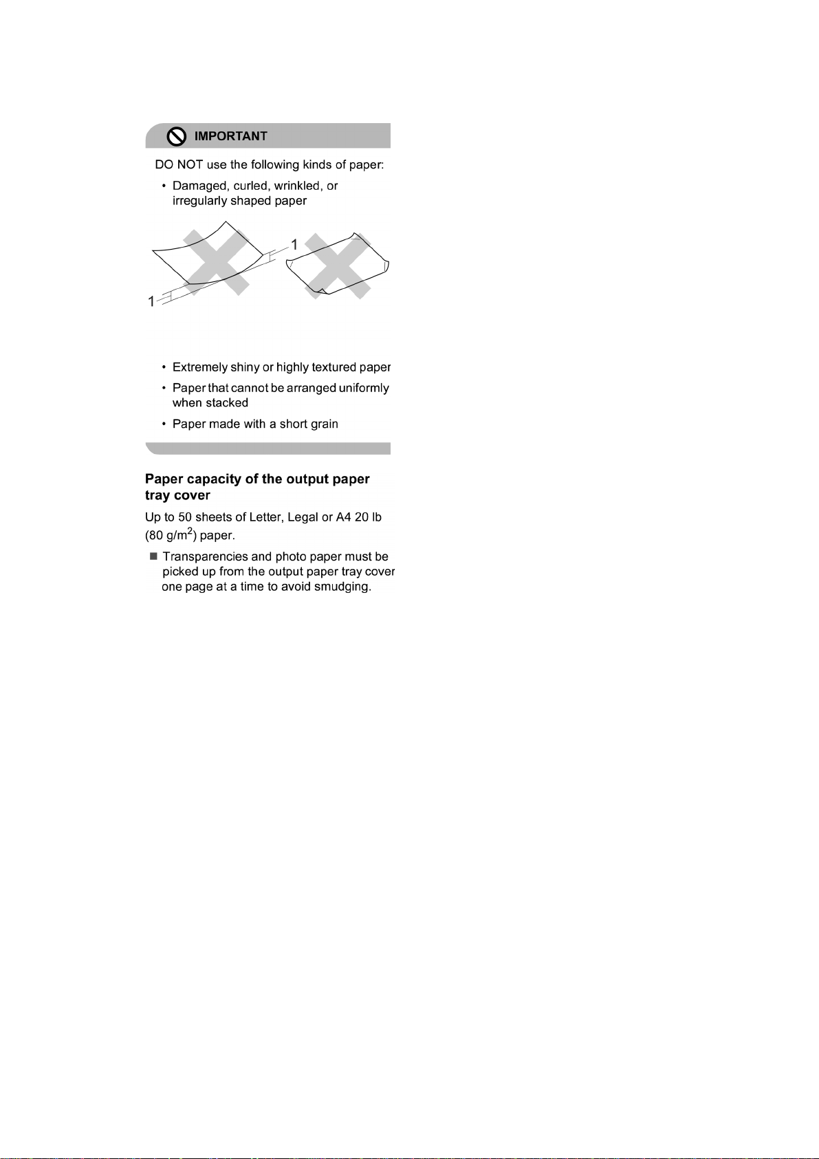
You can only print on both sides of the paper with PC printing using Windows.
1 0.08 inches (2 mm) or greater curve
may cause jams to occur
1-10
Confidential
Page 30
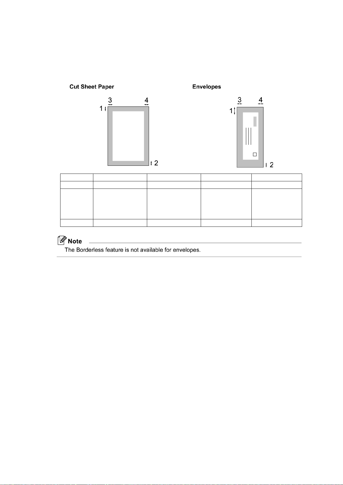
1.11.2 Printable Area
The printable area depends on the settings in the application you are using. The figures below
show the unprintable areas on cut sheet paper and envelopes. The machine can print in the
shaded areas of cut sheet paper only when the Borderless print feature is available and turned
on.
Top (1) Bottom (2) Left (3) Right (4)
Cut Sheet 3 mm (0.12 inches) 3 mm (0.12 inches) 3 mm (0.12 inches) 3 mm (0.12 inches)
Cut Sheet
(Duplex print
when using
Ledger or A3
size)
Envelopes 22 mm (0.86 inches) 22 mm (0.86 inches) 3 mm (0.12 inches) 3 mm (0.12 inches)
22 mm (0.86 inches) 22 mm (0.86 inches) 3 mm (0.12 inches) 3 mm (0.12 inches)
1-11
Confidential
Page 31

CHAPTER 2 ERROR INDICATION AND TROUBLESHOOTING
WARNING
2.1 INTRODUCTION
This section gives the service personnel some of the troubleshooting procedures to be followed
if an error or malfunction occurs with the machine. It is impossible to anticipate all of the
possible problems which may occur in future and determine the troubleshooting procedures, so
this section covers some sample problems. However, those samples will help service personnel
pinpoint and repair other defective elements if he/she analyzes and examines them well.
2.1.1 Precautions
Be sure to observe the following to prevent any secondary troubles from happening during
troubleshooting.
WARNING
DO NOT use flammable substances or organic solvent such as alcohol, benzine, thinner or
any type of spray to clean the insi de or outside of the machine. Doing this may cause a fire or
electrical shock.
Always unplug the AC power cord from the outlet when removing the covers and PCBs,
adjusting the mechanisms, or conducting continuity testing with a circuit tester.
(1) When disconnecting the connectors, do not pull the lead wires but hold the connector
housings.
(2) Static electricity charged in your body may damage electronic parts.
Before handling the PCBs, touch a metal portion of the machine to discharge static
electricity charged in your body. When transporting PCBs, be sure to wrap them in
conductive sheets.
When replacing the PCBs, put on a grounding wrist band and perform the job on a static
mat. Also take care not to touch the conductor sections on the flat cables.
(3) Be sure to observe the warnings
(4) After repairing the defective section, be sure to check again if the repaired section works
correctly.
2-1
Confidential
Page 32

2.1.2 Initial Check
Prior to proceeding to the troubleshooting procedures, make the following initial checks:
Environmental conditions
Check that:
(1) The machine is placed on a flat, firm surface.
(2) The machine is used in a clean environment at or near normal room temperature (10°C to
35°C) with normal relative humidity (20 to 80%).
(3) The machine is not exposed to direct sunlight, excessive heat, moisture, or dust.
Power requirements
Check that:
(1) The power supply specified on the rating plate on the machine is used. The supply voltage
stays within the rating ±10%.
(2) Each voltage level on AC input lines and DC lines is correct.
(3) All cables and h arnesses are firmly connected.
(4) The fuses are not blown.
Recording paper
Check that:
(1) A recommended type of recording paper is used. (Refer to Chapter 1, Section 1.11
"PAPER.")
(2) The recording paper is not dampened.
Ink cartridges
(1) Check that all of four ink cartridges are loaded.
Head/carriage unit
(1) Repeat the purge operation (Function code 76) several times. (Refer to Chapter 5, Section
5.1.4.27.)
2-2
Confidential
Page 33

2.2 OVERVIEW
r
2.2.1 Cross-section Drawings and Components
Document scanning and feeding mechanisms
Document feed roller 1
Second side scanning
CIS unit
ADF cover
Document
feed roller 2
(Left)
First side scanning
CIS unit
Document scanning position detection actuator
(for first side scanning)
Document separation roller
Separation rubber
Document width detection actuator
Document detection actuator
Document pull-in roller
ADF cover switch actuator
Document scanning position detection actuator
(for second side scanning)
Printing and paper feeding mechanisms
Registration sensor actuator
Intermediate roller
Paper feed roller
Document ejection roller
Head/carriage
unit
Recording paper
ejection roller
(Right)
Switchback paper detection actuato
Switchback roller
(Rear)
Paper feed
sensor actuator
T1 bank ASSY
T1 paper pull-in rollers
T2 bank ASSY
T2 paper pull-in rollers
Platen
2-3
DX roller
(Front)
Confidential
Page 34

2.2.2 Paper Path for Documents and Recording Paper
Document path in ADF scanning
Place a document face up
Recording paper p ath
Paper path from the
manual feed slot
Document path
in ADF scanning
Paper path in duplex printing
Paper path from paper tray #1
Paper path from paper tray #2
2-4
Confidential
Page 35

2.2.3 Parts Names and Functions
Document scanning and feeding
Names Functions
Document detection actuator
Document width detection actuator
Document pull-in roller This pulls documents loaded in the document tray into the
Document separation roller and
separation rubber
Document scanning position detection
actuator (for second side scanning)
Document feed roller 1 This feeds a document to the CIS unit (for second side
Document feed roller 2 This feeds a document to the CIS unit (for first side
Document scanning position detection
actuator (for first side scanning)
This detects whether documents are set on the document tray.
This detects whether documents loaded are A4 (letter) or B4/
A3 (ledger) in width.
ADF.
These feed document pages (drawn in by the document pull-
in roller) one at a time to the document feed roller 1.
This detects the leading edge of document pages, indicating
the scanning start position for second side scanning (only in
duplex scanning).
This also detects paper jams in the ADF.
scanning).
scanning).
This detects the leading edge of document pages, indicating
the scanning start position for first side scanning (only in
duplex scanning).
This also detects paper jams in the ADF.
Document ejection roller This ejects document pages that have been scanned, onto the
document cover.
2-5
Confidential
Page 36

Printing and paper feeding
Names Functions
T1 paper pull-in rollers
T2 paper pull-in rollers
Paper feed sensor actuator
These rollers pull in recording paper from paper tray #1.
These rollers pull in recording paper from paper tray #2.
This detects whether recording paper is fed from the paper tray by
detecting the leading edge of the paper for driving the intermediate
roller.
This also detects paper jams in the rear section of the machine.
Intermediate roller
This stops the leading edge of recording paper for alignment
(registration).
After registration, this roller rotates to feed the recording paper to
the paper feed roller.
Registration sensor actuator
This detects the leading and trailing edges of recording paper for
indicating the printing start position and for judging the paper size,
respectively.
In manual paper feeding, this detects whether recording paper is set
on the manual feed slot.
This also detects paper jams in the rear section of the machine.
Paper feed roller
This feeds recording paper to the printing position.
Recording paper ejection roller This feeds printed recordi ng paper to the switchback roller.
Switchback paper detection
actuator
This detects whether printed recording paper is ejected.
In duplex printing, it detects the trailing edge of the paper after
printing on the first side to determine the reversing timing of the
switchback roller, as well as judgi ng the paper size.
In duplex printing, it also detects whether recording paper has
passed through the DX chute or jammed in the DX chute.
This also detect paper jams in the paper ejection section.
Switchback roller
DX roller
This ejects recording paper to the paper ejection tray.
In duplex printing, after feeding of recording paper printed on its
first side by the specified amount, this roller reverses to feed the
paper to the duplex print paper path.
In duplex printing, this roller feeds paper passing through the duplex
print paper path, to the intermediate roller.
2-6
Confidential
Page 37

2.2.4 Block Diagram
Head/carriage unit
Head/carriage unit
Carriage PCB
CR encoder sensor
Paper width sensor
Head thermistor
Carriage motor
Paper feed motor
Switchback paper sensor PCB
Switchback paper sensor
PF encoder sensor PCB
Paper feed (PF) sensor PCB
Registration sensor PCB
Line
External Line
AC line
PF encoder sensor
Paper feed sensor
Registration sensor
MJ/PS shield unit
MJ PCB
Power supply
PCB
Control panel
unit
Control panel
PCB
Key matrix
Scanner
cover sensor
2-wire
2-wire
3-wire
4wire
7-wire
3wire
3-wire
2-wire
2-wire *
6-wire
Scanner cover
Touch panel *
1
(Scanner unit)
Touch panel *
1
relay PCB
Color
LCD
6-wire 4-wire 4-wire
CIS unit
(First side scanning,
black harness)
USB
5-wire in 6-wire
connector
housing
Wireless
LAN PCB
SDAA
3
6-wire *
AFE/LED Driver
Main
ASIC
MODEM
AMP
Digital camera
Speak er
4
/USB memory
CIS
motor
PC Network
USB LAN
EEPROM
DDR2
MAIN PCB
4-wire 2-wire2-wire
Backup
battery
[
LAN IC
ROM
Media
SD/MS/MS Duo
Ink cartridge
cover switch
7-wire
4-wire
3-wire
3-wire
3-wire *
6-wire *
2-wire
4-wire
4-wire
2-wire
2-wire
CIS unit (Second side scanning, white harness)
Document detection/width sensor PCB
Document detection sensor
Document width sensor (A3-size) *
Document scanning position sensor PCB (First side scanning)
Document scanning position sensor (First side scanning)
Document width sensor PCB
Document width sensor (B4-size) *
Document scanning position sensor PCB (Second side scanning)
3
4
Document scanning position sensor (Second side scanning)
ADF cover switch
ADF motor
3
4
ASF drive ASSY
ASF motor/encoder sensor PCB
6-wire
ASF encoder sensor
ASF motor
Maintenance unit
Purge cam switch
Ink cartridge detection sensor PCB
Ink cartridge detection sensors
High-yield ink cartridge sensor PCB
High-yield ink cartridge sensors
Ink remaining sensor PCB
Ink remaining sensors
Casing internal temperature thermistor
Ink refill ASSY
*1 For models with touch panel
*2 For duplex scanning models
*3 Fo r mo de ls destined for countries except Japan
*4 For Japa nese models
ADF unit
2-7
Confidential
Page 38

2.2.5 Components
ADF & document cover ASSY
Scanner cover
(Scanner unit)
Speaker spring
Control panel ASSY
with touch panel
Control panel ASSY
without touch panel
CIS flat cable cover
Speaker
Harness cover
Scanner cover
support
Registration
sensor PCB
ASSY
PF encoder/
PF sensor
harness unit
MJ PCB ASSY
Power supply PCB
ASSY
Flushing box
Lower MJ/PS
shield
Engine
unit
Lower cover
Front cover
Wireless LAN PCB
Flat cable support
Upper cover
Head/carriage unit
Maintenance unit +
ASF drive ASSY
Backup battery
Ink refill ASSY
Ink absorber box
Main PCB ASSY
Ink cartridge cover switch
Ink cartridge cover
Media module cover
Paper tray #1
Jam clear cover
LT cover*
2-8
Paper tray #2
(Lower tray)*
(COMPONENTS)
* For models with paper tray #2
Confidential
Page 39

2.3 ERROR INDICATION
To help the user or the service personnel promptly locate the cause of a problem (if any), the
machine incorporates the self-diagnostic functions which display error messages for equipment
errors.
2.3.1 Error Codes
Error
Code
0D
0E
0F
13
16
17
Contents
In duplex printing, a recording paper jam has occurred. (The switchback paper
sensor does not come ON within the specified paper feeding amount after the
start of switchbacking.)
In duplex printing, a sensor error has occurred during printing on the second
side. (During switchbacking, the combination of the sensing states of the
registration sensor, switchback paper sensor, and paper feed sensor has become
unexpected.)
In duplex printing, a recording paper jam has occurred. (During printing on the
second side, the switchback paper sensor does not go OFF even after the
recording paper is fed for the speci fied paper feeding amount.)
In duplex printing, a sensor error has occurred during printing on the second
side. (During printing on the second side, the user has drawn out recording
paper or bypass-fed paper.)
In paper ejecting after printing on the first side, a recording paper jam has
occurred. (The switchback paper sensor does not go OFF even after paper
ejection following printing on the first side with the switchback paper sensor
being ON.)
Recording paper size error. (Duplex PC print/Duplex copy) (Detected by the
paper width sensor or registration sensor)
Refer to
page:
2-22
2-23
2-24
2-24
2-25
2-25
In switchbacking of paper for pr inting on the seco nd side, a recordin g paper jam
18
20
21
22
23
24
26 Replace black ink cartridge. (Detected by the black ink remaining sensor) 2-29
27 Replace yellow ink cartridge. (Detected by the yellow ink remaining sensor) 2-29
has occurred. (The paper feed sensor do es not com e ON even after the recordin g
paper is fed for the specified paper feeding amount.)
Cannot identify a black ink cartridge. (The sensing timing of the ink remaining
sensor, i nk cartridge detection sensor and high-yield ink cartridge sensor is off.)
Cannot identify a yellow ink cartridge. (The sensing timing of the ink remaining
sensor, i nk cartridge detection sensor and high-yield ink cartridge sensor is off.)
Cannot identify a cyan ink cartridge. (The sensing timing of the ink remaining
sensor, i nk cartridge detection sensor and high-yield ink cartridge sensor is off.)
Cannot identify a magenta ink cartridge. (The sensing timing of the ink
remaining sensor, ink cartridge detection sensor and high-yield ink cartridge
sensor is off.)
An ink cartridge of wrong color is loaded. (A color ink cartridge is loaded in the
black ink cartridge slot.)
2-9
2-26
2-27
2-27
2-27
2-27
2-28
Confidential
Page 40

Error
Code
Contents
28 Replace cyan ink cartridge. (Detected by the cyan ink remaining sensor) 2-29
29 Replace magenta ink cartridge. (Detected by the magenta ink remaining sensor) 2-29
2A Black ink cartridge not loaded. (Detected by the ink cartridge detection sensor) 2-30
2B Y ellow ink cartridge not loaded. (Detected by the ink cartridge detection sensor) 2-30
2C Cyan ink cartridge not loaded. (Detected by the ink cartridge detection sensor) 2-30
Refer to
page:
2D
Magenta ink cartridge not loaded. (Detected by the ink cartridge detection
sensor)
2-30
2F Ink cartridge cover opened. 2-31
30 Carriage motor does not rotate. (Detected by the CR encoder) 2-31
31 Cannot detect the origin of the carriage. (Detected by the CR encoder) 2-32
32 Capping load large. 2-32
35
38
3B
3C
Head/carriage unit stopped during printing. (Error caused by any problem
except a paper jam when ink is not being jetted out)
Head/carriage unit stopped during printing. (Error caused by a paper jam when
ink is not being jetted out)
Head/carriage unit stopped during printing. (Error caused by any problem
except a paper jam when ink is being jetted out)
Head/carriage unit stopped during printing. (Error caused by a paper jam when
ink is being jetted out)
2-33
2-33
2-34
2-34
3E Any abnormality in the carriage motor, ASF motor, or paper feed motor. 2-35
3F Carriage motor does not stop. (Keeps rotating for 10 seconds or more) 2-35
40 Casing internal thermistor defective. (Detects -20ºC or below or 80ºC or higher) 2-36
42 Head drive voltage dropped below the lower limit. 2-36
43
Head thermistor defective. (Detects -20ºC or below or 80ºC or higher when the
power is turned on)
2-36
44 Abnormal temperature of the print head driver. 2-37
46 Purge count or flushing count overflown. 2-37
48 Head flat cables halfway connected. 2-37
49 Abnormal head drive voltage. (Does not rise to the specified level) 2-38
4F
The head drive voltage has dropped from the high to low level in an abnormally
short period.
2-38
50 Purge cam switch does not come ON or go OFF. 2-38
52
Failed to detect the origin of the purge cam. (Failed to detect the longest OFF
domain of the purge cam)
2-10
2-39
Confidential
Page 41

Error
Code
Contents
5A Abnormal stop of purge cam being driven. 2-39
Refer to
page:
5B
5D
Abnormal stop of pump in the maintenance unit (during expelling/sucking of
air).
Driver IC overcurrent protection activated when the purge cam was being
driven.
2-39
2-40
5E D river IC overcurrent protection activated when the pump was in operation. 2-40
60 Paper width sensor does not come ON. 2-41
61 Light intensity adjustment failure of paper width sensor. 2-41
62 Paper width sensor positioning failure. 2-41
6C Driver IC overcurrent protection act ivated during running of the A SF motor. 2-42
6F ASF motor does not stop. (Keeps rota t ing for 15 seconds or more) 2-42
75 Head capping failed at the maintenance unit. 2-43
76 Head uncapping failed at the maintenance unit. 2-43
7A
7B
7D
Abnormal stop of the purge cam during head capping. (When being driven in
the capping direction)
Abnormal stop of the purge cam during head capping. (When being driven in
the uncapping direction)
Driver IC overcurrent protection activated when the purge cam was being
driven.
2-44
2-44
2-44
7E Head property data not entered. 2-45
80
81
82
83
Recording paper size error. (During fax/list printing) (Paper size not su itable for
fax receiving was detected by the paper width sensor or registration sensor.)
Recording paper size error. (Except during fax/list printing) (That the recording
paper width is less than the specified one is detect ed by the paper wid th sens or.)
Recording paper jam in paper feeding. (The paper width sensor has failed to
detect the leading edge of paper.)
Recording paper jam in paper feeding. (The registration sensor does not come
ON.)
2-45
2-46
2-46
2-47
Recording paper jam in paper ejecting. (Any of the paper feeding sensor,
84
registration sensor and switchback paper sensor sticks to ON even after
2-48
completion of paper ejection.)
Recording paper jam during printing. (Although recording paper advances for
88
the specified amount during printing, the switchback paper sensor does not
2-49
come ON.)
89 Failed to detect the leading edge of recording paper. 2-49
2-11
Confidential
Page 42

Error
Code
Contents
8A PF encoder cannot detect the rotation of the paper feed roller. 2-50
8B PF encoder detects an abnormal stop of the paper feed roller. 2-50
Refer to
page:
8C
Driver IC overcurrent protection activated during running of the paper feed
motor.
2-51
8F Paper feed motor cannot stop. 2-51
A1 Scanner cover (scanner unit) opened. 2-52
A2 In ADF scanning, a document of 90 cm or longer is detected. 2-52
A3
The document scanning position sensor (for first side scanning) or the one (for
second side scanning) does not come ON during ADF scanning.
2-53
A4 ADF cover opened. 2-54
A5 Fax scanning failure by the first side scanning CIS (1st time). 2-54
A6 Fax scanning failure by the first side scanning CIS (retry). 2-54
A7 Mismatch between actual CIS type and EEPROM data. 2-55
A8 Color parameter matching error. (Used for monitoring bugs at the factory.) 2-55
AC Fax scanning failure by the second side scanning CIS (1st time). 2-55
AF Positioning error of the first side scanning CIS. (Home positioning failed) 2-56
BC Fax scanning failure by the second side scanning CIS (retry). 2-56
BD Black level data error in flat-bed scanning. 2-56
BF
During the second side scanning in the ADF, a document longer than the
specified limit is detected.
2-57
DF SDAA failure. 2-57
E0 Modem cannot start up normally even after reset. 2-57
E2 Wired MAC address not registered. 2-58
E3 Wireless MAC address not registered. 2-58
E5 Unidentifiable error. 2-58
E6 Write error in EEPROM. 2-58
E7 Unidentifiable error. 2-59
EA Document removed at phase B. (Detected by the document detection sensor) 2-59
EC LCD failure. 2-59
ED Touch panel initial i zati on fail ed. 2-60
F8 Battery harness connection failure. 2-60
FE ROM data acquisition error. 2-60
2-12
Confidential
Page 43

2.3.2 Error Messages
Error Message Contents
B&W Print Only One or more of the color ink cartridges have
reached the end of their life.
BT Call Sign On
(U.K. only)
MFC-J6910DW
Cannot Detect Cannot detect an ink cartridge correctly. 20, 21, 22, 23 p. 2-27
Cannot Print
Comm.Error
Connection Fail Failed to connect to the other end. - Section
Cover is Open
Data Remaining
Disconnect device
from front connect or
& turn machine off &
then on
BT Call Sign is set to ON, so the Receive Mode
cannot be changed.
The service life of any ink cartridge has
expired. Or a paper jam or an abnormality has
occurred in the machine.
Fax communication error.
Any of the ink cartridge cover, scanner cover
and ADF cover is opened.
Memory full so that data processing is
impossible.
A USB device not supported by the machine is
connected or the connected USB device is
defective.
Error Code Refer to:
27, 28, 29 p. 2-29
- Section
2.4.9.8
-
- Section
2.4.9.3
2.4.9.3
2F
A1
A4
- Section
- Section
p. 2-31
p. 2-52
p. 2-54
2.4.10.4
2.4.10.3
Disconnected
Document Jam/
Too long
DR Mode in Use The Distinctive Ringing mode is ON so that the
High Temperature
Hub is Unusable.
Image Too Long.
Image Too Small.
Fax communications line not connected or data
send/receive not possible.
Document jam or too long document in the
ADF.
Receive Mode cannot be changed.
The room temperature is high.
A USB hub or a hub built-in USB device is
connected.
In using the PhotoCapture Center, the image is
too long to correct or trim.
In using the PhotoCapture Center, the image is
too small to correct or trim.
- Section
2.4.9.3
A2
A3
BF
EA
- Section
40 p. 2-36
- Section
-
-
p. 2-52
p. 2-53
p. 2-57
p. 2-59
2.4.9.8
2.4.10.3
2-13
Confidential
Page 44

Error Message Contents
Error Code Refer to:
Ink Absorber Full Purge count or flushing count overflown. 46 p. 2-37
Low Temperature
Media Error
The room temperature is low.
The memory card is either corrupted or
40 p. 2-36
- Section
improperly formatted.
Media is Full. When the memory card or USB flash memory
- Section
drive loaded in the machine already contains
1,000 or more image files (including folders),
you tried to execute "Scan to Media."
No Caller ID
No File
No caller ID information has been received.
The memory card or USB flash memory drive
- Section
- Section
loaded in the machine contains no printable fi le.
No Ink Cartridge No ink cartridge is loaded. 2A, 2B, 2C,
2D
No Paper Fed
Not Registered
No paper is loaded in the paper tray(s).
One Touch or Speed Dial number is not
- Section
registered.
No Response/Busy
The number dialed does not answer or is busy.
Out of Fax Memory Data stored in the memory by Memory Send/
- Section
- Section
Receive operation has exceeded the allowable
memory space.
2.4.10.3
2.4.10.3
2.4.9.9
2.4.10.3
p. 2-30
Section
2.4.2.1
2.4.9.2
2.4.9.3
2.4.10.4
Out of Memory
Paper Jam
Please Disconnect
USB Device.
Replace Ink
Touchscreen
initialization failed
MFC-J6910DW
The machine’s memory is full.
Recording paper is jammed in the machine.
A USB device not supported by the machine is
connected.
One or more of the ink cartridges have reached
the end of their life.
The touch screen was pressed before
completion of power-on initialization.
- Section
2.4.10.4
0D
0E
0F, 13
16
18
31
38
3C
82
83
84
88
8A, 8B
8C
p. 2-22
p. 2-23
p. 2-24
p. 2-25
p. 2-26
p. 2-32
p. 2-33
p. 2-34
p. 2-46
p. 2-47
p. 2-48
p. 2-49
p. 2-50
p. 2-51
- Section
2.4.10.3
26, 27, 28, 29 p. 2-29
ED p. 2-60
Unusable Device
A USB flash memory drive not supported by
the machine is connected.
2-14
-
Confidential
Page 45

Error Message Contents
Wrong Ink Color
An ink cartridge of wrong color is loaded. (A
color ink cartridge is loaded in the black ink
cartridge slot.)
Wrong Paper Size
Recording paper of a size other than the preset
size is loaded in the paper tray.
Error Code Refer to:
24 p. 2-28
17
80
81
p. 2-25
p. 2-45
p. 2-46
Wrong Tray Setting
(MFC-J6710DW/
MFC-J6910DW)
Tray setting made in the machine is wrong. 81 p. 2-46
2-15
Confidential
Page 46

2.3.3 Communications Error Codes
Code 1 Code 2 Cause Refer to:
10 08 Wrong number called. Section 2.4.9.7
11 01 No dial tone detected before start of dialing.
11 02 Busy tone detected before dialing.
11 03 2nd dial ton e not detected.
11 05 No loop current detected.
11 06 Busy tone detected after dialing or called.
11 07 No response from the remote station in sending.
11 10 Unobtainable tone detected after dialing.
17 07 No response from the calling station in receiving.
20 01 Unable to detect a flag field.
20 02 Carrier was OFF for 200 milliseconds or longer.
20 03 Abort detected ("1" in succession for 7 bits or more).
20 04 Overrun detected.
20 05 A frame for 3 seconds or more received.
*1
20 06 CRC error in answerback.
20 07 Error command received.
20 08 Invalid command received.
20 09 Command ignored once for document setting or for
dumping-out at turn-around transmission.
20 0A T5 time-out error.
20 0B CRP received.
20 0C EOR and NULL received.
*1 Available in German models only.
2-16
Confidential
Page 47

Code 1 Code 2 Cause Refer to:
32 01 Remote terminal only with V.29 capability in 2,400 or
4,800 bps transmission.
32 02 Remote terminal not ready for polling.
32 10 Remote terminal not equipped with password
function or its password switch OFF.
32 11 Remote terminal not equipped with or not ready for
confidential mailbox function.
32 12 Remote terminal not equipped with or not ready for
relay broadcasting function.
32 13 No confidential mail in the remote terminal.
32 14 The available memory space of the remote terminal is
less than that required for reception of the
confidential or relay broad-casting instruction.
32 18 Remote terminal not equipped with color function.
40 02 Illegal coding system requested.
40 03 Illegal recording width requested.
40 05 ECM requested although not allowed.
40 06 Polled while not ready.
Section 2.4.9.7
40 07 No document to send when polled.
40 10 Nation code or manufacturer code not coincident.
40 13 Polled by any other manufacturers' terminal while
waiting for secure polling.
40 17 Invalid resolution selected.
40 20 Invalid full-color mode requested.
50 01 Vertical resolution capability changed after
compensation of background color.
63 01 Password plus "lower 4 digits of telephone number"
not coincident.
63 02 Password not coincident.
63 03 Polling ID not coincident.
74 DCN received.
80 01 Fallback impossible.
90 01 Unable to detect video signals and commands within
6 seconds after CFR is transmitted.
90 02 Received PPS containing invalid page count or block
count.
2-17
Confidential
Page 48

Code 1 Code 2 Cause Refer to:
A0 03 Error correction sequence not terminated even at the
final transmission speed for fallback.
A0 11 Receive buffer empty. (5-second time-out)
A0 12 Receive buffer full during operation excep t receiving
into memory.
A0 13 Decoding error continued on 500 lines.
A0 14 Decoding error continued for 10 seconds.
A0 15 Time-out: 13 seconds or more for one-line
transmission.
A0 16 RTC not found and carrier OFF signal detected for 6
seconds.
A0 17 RTC found but no command detected for 60 seconds.
A0 19 Receive buffer full during receiving into memory.
A8 01 RTN, PIN, or ERR received at the calling terminal.
A9 01 RTN, PIN, or ERR received at the called terminal.
*1
*1
AA 18 Receive buffer full during receiving into memory.
B0 02 Unable to receive the next-page data.
B0 03 Unable to receive polling even during turn-around
transmission due to call reservation.
Section 2.4.9.7
B0 04 PC interface error .
BF 01 Communication canceled by pressing the STOP key
before establishment of FAX communication*2.
BF 02 Communication canceled by pressing the STOP key
after establishment of FAX communication
*2
.
BF 03 Transmission canceled due to a scanning error c aused
by no document or document feed problem in ADF
scanning in real time transmission.
*1 Available in German models only.
*2 Establishment of FAX communication
FAX commu nication is established when the calling station receives a DIS (reception capability) signal
from the called station and the called station receives an NSS or DCS (communications test) signal from
the calling station.
2-18
Confidential
Page 49

Code 1 Code 2 Cause Refer to:
C0 01
C0 02
C0 03
C0 04
No common modulation mode or polling failed.
Unable to detect JM.
Unable to detect CM.
Unable to detect CJ.
C0 10 V. 34 negotiation or training not finished.
C0 11
Modem error detected during V. 34 negotiation or
training.
C0 20
C0 21
Modem error detected during sending of commands.
Modem error detected during receiving of
commands.
C0 22
C0 30
Control channel connection timeout.
Modem error detected during sending of image
signals.
C0 31
Modem error detected during receiving of image
signals.
E0 01 Failed to detect 1,300 Hz signal in burn-in operation.
E0 02 Failed to detect PB si gnals in burn-in operation.
Section 2.4.9.7
FF XX Equipment error . (For X
"Error Codes.")
X, refer to Section 2.3.1
2-19
Confidential
Page 50

2.3.4 Status Monitor Errors
Error Message Contents Error Code Refer to:
Cover is Open Any cover opened. 2F
A1
A4
Document Jam Document jam detected in the ADF. A2
A3
p. 2-31
p. 2-52
p. 2-54
p. 2-52
p. 2-53
High Temperature The room temperature is high. 40 p. 2-36
Ink Absorber Full Purge count or flashing count overflown. 46 p. 2-37
Ink Absorber Near
Full
Ink low The service life of any ink cartridge will be
Purge count or flashing count approaching
overflow .
-
-
expired soon.
Low Temper ature The room temperature is low. 40 p. 2-36
No Ink Cartridge Ink cartridge not loaded. 2A, 2B, 2C, 2Dp. 2-30
No Paper Fed No paper loaded in paper tray(s). 18 p. 2-26
Offline Machine is offline. - Section
2.4.9.3
Out of Memory The memory is full. - Section
2.4.10.4
Paper Jam Recording paper jam. 0D
0E
0F, 13
16
18
31
38
3C
82
83
84
88
8A, 8B
8C
Replace Ink The service life of any ink cartridge has
26, 27, 28, 29 p. 2-29
expired.
Wrong Paper Size The recording paper size is different from
the specified one.
The recording paper size is not supported in
17
80
81
duplex printing.
p. 2-22
p. 2-23
p. 2-24
p. 2-25
p. 2-26
p. 2-32
p. 2-33
p. 2-34
p. 2-46
p. 2-47
p. 2-48
p. 2-49
p. 2-50
p. 2-51
p. 2-25
p. 2-45
p. 2-46
2-20
Confidential
Page 51

Error Message Contents Error Code Refer to:
Unable to Print 3X Errors around the head/carriage unit. 30 to 3F p. 2-31 to
p. 2-35
Unable to Print 5X Errors around the maintenance unit. 50 to 5E p. 2-38 to
p. 2-40
Unable to Print 7X 75 to 7E p. 2-43 to
p. 2-45
Unable to Scan AX Errors around the scanner. A2 to AF p. 2-52 to
p. 2-56
Unable to Print XX Errors other than 3X, 5X, 7X, and AX. Codes other
than 3X, 5X,
7X and AX
p. 2-36 to
p. 2-60
2-21
Confidential
Page 52

2.4 TROUBLESHOOTING
2.4.1 Error Cause and Solutions
First see the user check items. If it cannot recover the machine, proceed to the troubleshooting
table exclusive to service personnel.
Error Code 0D
Paper Jam
LCD
In duplex printing, a recording paper jam has occurred. (The switchback paper sensor does not
come ON within the specified paper feeding amount after the start of switchbacking.)
User Check
- Remove the jammed paper.
- Check whether the recording paper being used is within the specification.
- Check that the recording paper is not curled.
- Clean the switchback (SB) roller.
Step Cause Solution
1 Foreign materials inside the
engine unit
2
3
4
5
Switchback paper detection
actuator out of place
Switchback paper sensor harness
connection failure
Switchback paper sensor
defective
Main PCB defective
Remove the foreign materials.
Set the actuator into place.
Check the connection and reconnect the harness.
Replace the sensor PCB ASSY.
Replace the main PCB ASSY.
2-22
Confidential
Page 53

Error Code 0E
Paper Jam
LCD
In duplex printing, a sensor error has occurred during printing on the second side. (During
switchbacking, the combination of the sensing states of the registration sensor, switchback
paper sensor, and paper feed sensor has become unexpected.)
User Check
- Remove the jammed paper.
- Check whether the recording paper being used is within the specification.
- Check that the recording paper is not curled.
- Clean the switchback (SB) roller.
Step Cause Solution
1 Switchback paper detection
actuator caught on the
surrounding parts
2 Paper feed sensor actuator caught
on the surrounding parts
3 Registration sensor actuator
caught on the surrounding parts
Reposition the actuator.
Reposition the actuator.
Reposition the actuator.
4 Switchback paper sensor
defective
5 Paper feed sensor defective Replace the PF encoder/PF sensor harness unit.
6 Registration sensor defective Replace the registration sensor PCB ASSY.
7 Main PCB defective Replace the main PCB ASSY.
Replace the sensor PCB ASSY.
2-23
Confidential
Page 54

Error Code 0F
Paper Jam
LCD
In duplex printing, a recording paper jam has occurred. (During printing on the second side, the
switchback paper sensor does not go OFF even after the recording paper is fed for the specified
paper feeding amount.)
User Check
- Remove the jammed paper.
- Check whether the recording paper being used is longer than the specified limit.
- Clean the switchback (SB) roller.
Step Cause Solution
1 Switchback paper detection
actuator caught on the
surrounding parts
2
Error Code 13
Main PCB defective
Reposition the actuator.
Replace the main PCB ASSY.
Paper Jam
LCD
In duplex printing, a sensor error has occurred during printing on the second side. (During
printing on the second side, the user has drawn out recording paper or bypass-fed paper.)
User Check
- Remove the jammed paper
- Clean the switchback (SB) roller..
Step Cause Solution
1 Switchback paper detection
actuator caught on the
surrounding parts
2 Paper feed sensor actuator caught
on the surrounding parts
3 Registration sensor actuator
caught on the surrounding parts
4 Switchback paper sensor
defective
5 Paper feed sensor defective Replace the PF encoder/PF sensor harness unit.
Reposition the actuator.
Reposition the actuator.
Reposition the actuator.
Replace the sensor PCB ASSY.
6 Registration sensor defective Replace the registration sensor PCB ASSY.
2-24
Confidential
Page 55

Error Code 16
Paper Jam
LCD
In paper ejecting after printing on the first side, a recording paper jam has occurred. (The
switchback paper sensor does not go OFF even after paper ejection following printing on the
first side with the switchback paper sensor being ON.)
User Check
- Remove the jammed paper.
- Clean the switchback (SB) roller.
Step Cause Solution
1 Foreign materials inside the
engine unit
2 Switchback paper detection
actuator out of place
3 Switchback paper sensor harness
connection failure
4 Switchback paper sensor
defective
5
Main PCB defective
Remove foreign materials.
Set the actuator into place.
Check the connection and reconnect the harness.
Replace the sensor PCB ASSY.
Replace the main PCB ASSY.
Error Code 17
Wrong Paper Size
LCD
Recording paper s iz e err or. (Duplex PC prin t/ Dupl ex copy) (Detected by the paper width sensor
or registration sensor)
User Check
- Check whether the recording paper being used is within the specification.
- Check that dark recording paper is not used.
Step Cause Solution
1 Registration sensor actuator
caught on the surrounding parts
2 PF encoder disk stained Replace the PF encoder disk and clean the flushing
3 Registration sensor defective Replace the registration sensor PCB ASSY.
4 Paper feed motor defective Replace the paper feed motor ASSY.
5 Paper width sensor defective Replace the carriage PCB ASSY.
Reposition the actuator.
guide. (Refer to Chapter 3, Section 3.1 .)
6 Main PCB defective Replace the main PCB ASSY.
2-25
Confidential
Page 56

Error Code 18
Paper Jam
LCD
In switchbacking of paper for printing on the second side, a recording paper jam has occurred.
(The paper feed sensor does no t come ON eve n aft er the reco rdi ng pa per is f ed fo r the specified
paper feeding amount.)
User Check
- Remove the jammed paper.
- Check whether the recording paper being used is within the specification.
- Clean the switchback (SB) roller.
Step Cause Solution
1 Foreign materials in the duplex
print paper path
2 Paper feed sensor actuator caught
on the surrounding parts
3
Main PCB defective
Remove foreign materials.
Reposition the actuator.
Replace the main PCB ASSY.
2-26
Confidential
Page 57

Error Code 20
Cannot Detect / Install Starter Ink
LCD
Cannot identify a black ink cartridge. (The sensing timing of the ink remaining sensor, ink
cartridge detection sensor and high-yield ink cartridge sensor is off.)
Error Code 21
Cannot Detect / Install Starter Ink
LCD
Cannot identify a yellow ink cartridge. (The sensing timing of the ink remaining sensor, ink
cartridge detection sensor and high-yield ink cartridge sensor is off.)
Error Code 22
Cannot Detect / Install Starter Ink
LCD
Cannot identify a cyan ink cartridge. (The sensing timing of the ink remaining sensor, ink
cartridge detection sensor and high-yield ink cartridge sensor is off.)
Error Code 23
Cannot Detect / Install Starter Ink
LCD
Cannot identify a magenta ink cartridge. (The sensing timing of the ink remaining sensor, ink
cartridge detection sensor and high-yield ink cartridge sensor is off.)
User Check
- Reload the ink cartridge.
- Replace the ink cartridge.
Step Cause Solution
1 Ink cartridge detection sensor
defective
2 Ink remaining sensor or high-
yield ink cartridge sensor failure
3 Main PCB defective Replace the main PCB ASSY.
Replace the ink cartridge detection sensor.
Replace the ink refill ASSY.
2-27
Confidential
Page 58

Error Code 24
Wrong INK Color
LCD
An ink cartridge of wrong color is loaded. (A color ink cartridge is loaded in the black ink
cartridge slot.)
User Check
- Load the ink cartridge into place.
- Replace the ink cartridge.
Step Cause Solution
1 Ink cartridge detection sensor
defective
2 Ink remaining sensor or high-
yield ink cartdige sensor failure
3 Main PCB defective Replace the main PCB ASSY.
Replace the ink cartridge detection sensor.
Replace the ink refill ASSY.
2-28
Confidential
Page 59

Error Code 26
Cannot Print
LCD
Replace INK [Black]
Replace black ink cartridge. (Detected by the black ink remaining sensor)
Error Code 27
Cannot Print
LCD
Replace INK [Yellow]
Replace yellow ink cartridge. (Detected by the yellow ink remaining sensor)
Error Code 28
Cannot Print LCD
Replace INK [Cyan]
Replace cyan ink cartridge. (Detected by the cyan ink remaining sensor)
Error Code 29
Cannot Print
LCD
Replace INK [Magenta]
Replace magenta ink cartridge. (Detected by the magenta ink remaining sensor)
User Check
- Reload the ink cartridge.
- Replace the ink cartridge.
Step Cause Solution
1 Ink remaining sensor defective Replace the ink refill ASSY.
2 Main PCB defective Replace the main PCB ASSY.
2-29
Confidential
Page 60

Error Code 2A
No INK Cartridge Black
Black ink cartridge not loaded. (Detected by the ink cartridge detection sensor)
Error Code 2B
No INK Cartridge Yellow
Yellow ink cartridge not loaded. (Detected by the ink cartridge detection sensor)
Error Code 2C
No INK Cartridge Cyan
Cyan ink cartridge not loaded. (Detected by the ink cartridge detection sensor)
Error Code 2D
No INK Cartridge Magenta
LCD
LCD
LCD
LCD
Magenta ink cartridge not loaded. (Detected by the ink cartridge detection sensor)
User Check
- Reload the ink cartridge.
- Replace the ink cartridge.
Step Cause Solution
1 Ink cartridge detection sensor
defective
2 Main PCB defective Replace the main PCB ASSY.
Replace the ink cartridge detection sensor PCB
ASSY.
2-30
Confidential
Page 61

Error Code 2F
Cover is Open
Ink cartridge cover opened.
User Check
- Close the ink cartridge cover.
Step Cause Solution
1 Boss on the ink cartridge cover,
working as an actuator for the ink
cartridge cover switch, broken
2 Connection failure of the ink
cartridge cover switch harness
3 Ink cartridge cover switch failure Replace the ink cartridge cover switch.
4 Main PCB defective Replace the main PCB ASSY.
Error Code 30
Replace the ink cartridge cover.
Check the connection and reconnect the harness.
Unable to Print 30 / Unable to Clean 30 / Unable to Init. 30
LCD
LCD
Carriage motor does not rotate. (Detected by the CR encoder)
User Check
- Remove the jammed paper.
Step Cause Solution
1 CR timing belt or pulley out of
place
2 Foreign materials on the CR
timing belt or around the head/
carriage unit
3 Carriage motor harness
connection failure
4 Leveler roller (LR) ASSY not
mounted correctly on the head/
carriage unit
5 CR encoder strip out of place Reposition the encoder strip.
6 CR encoder strip stained Replace the encoder strip.
7 CR encoder sensor failure Replace the carriage PCB ASSY.
8 Carriage motor defective Replace the carriage motor.
Reposition the CR timing belt or the pulley.
Remove foreign materials.
Check the connection and reconnect the harness.
Set the LR ASSY into place, using the LR jigs (LR
positioning jig and LR fitting jig).
9 Main PCB defective Replace the main PCB ASSY.
2-31
Confidential
Page 62

Error Code 31
Paper Jam
Cannot detect the origin of the carriage. (Detected by the CR encoder)
User Check
- Remove foreign materials.
Step Cause Solution
1 Foreign materials on the CR
timing belt or around the head/
carriage unit
2 Switching lever guide out of place Reposition the switching lever guide.
3 CR encoder strip stained Replace the encoder strip.
4 Maintenance unit defective Clean the maintenance unit or replace it.
5 Main PCB defective Replace the main PCB ASSY.
Error Code 32
Remove foreign materials.
LCD
Unable to Print 32 / Unable to Clean 32 / Unable to Init. 32
Capping load large.
User Check
- Remove the jammed paper.
Step Cause Solution
1 Switching lever guide out of place Reposition the switching lever guide.
2 Leveler roller (LR) ASSY not
mounted correctly on the head/
carriage unit
3 Maintenance unit defective Clean the maintenance unit or replace it.
Set the LR ASSY into place, using the LR jigs (LR
positioning jig and LR fitting jig).
LCD
2-32
Confidential
Page 63

Error Code 35
Unable to Print 35 / Unable to Clean 35 / Unable to Init. 35
LCD
Head/carriage unit stopped during printing. (Error caused by any problem except a paper jam
when ink is not being jetted out)
User Check
- Remove the jammed paper.
Step Cause Solution
1 Foreign materials on the CR
timing belt or around the head/
carriage unit
2 Switching lever guide out of place Reposition the switching lever guide.
3 Leveler roller (LR) ASSY not
mounted correctly on the head/
carriage unit
4 CR encoder strip stained Replace the encoder strip.
5 Maintenance unit defective Clean the maintenance unit or replace it.
Remove foreign materials.
Set the LR ASSY into place, using the LR jigs (LR
positioning jig and LR fitting jig).
Error Code 38
Paper Jam
LCD
Head/carriage unit stopped during printing. (Error caused by a paper jam when ink is not being
jetted out)
User Check
- Remove the jammed paper.
Step Cause Solution
1 Foreign materials on the CR
timing belt or around the head/
carriage unit
2 Leveler roller (LR) ASSY not
mounted correctly on the head/
carriage unit
3 CR encoder strip stained Replace the encoder strip.
4 Maintenance unit defective Clean the maintenance unit or replace it.
Remove foreign materials.
Set the LR ASSY into place, using the LR jigs (LR
positioning jig and LR fitting jig).
2-33
Confidential
Page 64

Error Code 3B
Unable to Print 3B / Unable to Clean 3B / Unable to Init. 3B
LCD
Head/carriage unit stopped during printing. (Error caused by any problem except a paper jam
when ink is being jetted out)
User Check
- Remove the jammed paper.
Step Cause Solution
1 Foreign materials on the CR
timing belt or around the head/
carriage unit
2 Leveler roller (LR) ASSY not
mounted correctly on the head/
carriage unit
3 Switching lever guide out of place Reposition the switching lever guide.
4 CR encoder strip stained Replace the encoder strip.
5 Maintenance unit defective Clean the maintenance unit or replace it.
Remove foreign materials.
Set the LR ASSY into place, using the LR jigs (LR
positioning jig and LR fitting jig).
Error Code 3C
Paper Jam
LCD
Head/carriage unit stopped during printing. (Error caused by a paper jam when ink is being
jetted out)
User Check
- Remove the jammed paper.
Step Cause Solution
1 Foreign materials on the CR
timing belt or around the head/
carriage unit
2 Leveler roller (LR) ASSY not
mounted correctly on the head/
carriage unit
3 CR encoder strip stained Replace the encoder strip.
4 Maintenance unit defective Clean the maintenance unit or replace it.
Remove foreign materials.
Set the LR ASSY into place, using the LR jigs (LR
positioning jig and LR fitting jig).
2-34
Confidential
Page 65

Error Code 3E
Unable to Print 3E / Unable to Clean 3E / Unable to Init. 3E
Any abnormality in the carriage motor, ASF motor, or paper feed motor.
Step Cause Solution
1
2
3
4
5
Error Code 3F
Foreign materials in the recording
paper path
Foreign materials in the
maintenance unit
Maintenance unit defective Replace the maintenance unit.
Engine unit defective Replace the engine unit.
Main PCB defective
Remove foreign materials.
Remove foreign materials.
Replace the main PCB ASSY.
Unable to Print 3F / Unable to Clean 3F / Unable to Init. 3F
LCD
LCD
Carriage motor does not stop. (Keeps rotating for 10 seconds or more)
Step Cause Solution
1
2 CR encoder strip stained Replace the encoder strip.
3
4
Carriage motor harness
connection failure
Carriage motor defective Replace the carriage motor.
Main PCB defective
Check the connection and reconnect the harness.
Replace the main PCB ASSY.
2-35
Confidential
Page 66

Error Code 40
Unable to Init. 40
LCD
Casing internal thermistor defective. (Detects -20ºC or below or 80ºC or higher)
Step Cause Solution
1 Casing internal temperature
thermistor defective
2 Main PCB defective Replace the main PCB ASSY.
Error Code 42
Unable to Print 42
Replace the ink refill ASSY.
LCD
Head drive voltage dropped below the lower limit.
User Check
- This error may occur when the ambient temperature is low. Increase the ambient temperat ure for
use of the machine.
Step Cause Solution
1 Connection failur e of the carriage-
head flat cable or head flat cables
2 Print head defective Replace the head/carriage unit.
3 Power supply PCB defective Replace the power supply PCB.
4 Main PCB defective Replace the main PCB ASSY.
Error Code 43
Unable to Print 43
Check the connection and reconnect the
corresponding flat cable(s).
LCD
Head thermistor defective. (Detects -20ºC or below or 80ºC or higher when the power is turned
on)
Step Cause Solution
1 Connection failur e of the carriage-
head flat cable or head flat cables
2 Head temperature thermistor
defective
Check the connection and reconnect the
corresponding flat cable(s).
Replace the carriage PCB ASSY.
3 Main PCB defective Replace the main PCB ASSY.
2-36
Confidential
Page 67

Error Code 44
Unable to Print 44
Abnormal temperature of the print head driver.
Step Cause Solution
1 Connection failure of the carriage-
head flat cable or head flat cables
2
3
4
Error Code 46
Head property data not entered Enter the head property data.
Print head defective Replace the head/carriage unit.
Main PCB defective
Check the connection and reconnect the
corresponding flat cable(s).
Replace the main PCB ASSY.
Unable to Print 46
Ink Absorber Full
Purge count or flushing count overflown.
LCD
LCD
Step Cause Solution
1
*
For the resetting procedures of the flushing count, refer to Chapter 4, Section 4.4.
Error Code 48
Ink absorber box and flushing box
full of ink
Replace the ink absorber box and flushing box, then
reset their counts. *
Unable to Init. 48
Head flat cables halfway connected.
Step Cause Solution
1 Connection failure of the carriage-
head flat cable or head flat cables
2
3
Print head defective Replace the head/carriage unit.
Main PCB defective
Check the connection and reconnect the
corresponding flat cable(s).
Replace the main PCB ASSY.
LCD
2-37
Confidential
Page 68

Error Code 49
Unable to Print 49
LCD
Abnormal head drive voltage. (Does not rise to the specified level)
Error Code 4F
Unable to Print 4F
LCD
The head drive voltage has dropped from the high to low level in an abnormally short period.
Step Cause Solution
1 Connection failur e of the carriage-
head flat cable or head flat cables
2 Print head defective Replace the head/carriage unit.
3 Power supply PCB defective Replace the power supply PCB.
4 Main PCB defective Replace the main PCB ASSY.
Check the connection and reconnect the
corresponding flat cable(s).
Error Code 50
Unable to Print 50 / Unable to Clean 50 / Unable to Init. 50
Purge cam switch does not come ON or go OFF.
Step Cause Solution
1 Foreign materials in the
maintenance unit
2 Purge cam switch harness
connection failure
3 ASF switching gear(s) broken Replace the ASF switching gear(s).
4 Paper feed motor defective Replace the paper feed motor.
5 Maintenance unit defective Replace the maintenance unit.
6 Main PCB defective Replace the main PCB ASSY.
Remove foreign materials.
Check the connection and reconnect the harness.
LCD
2-38
Confidential
Page 69

Error Code 52
Unable to Print 52 / Unable to Clean 52 / Unable to Init. 52
LCD
Failed to detect the origin of the purge cam. (Failed to detect the longest OFF domain of the
purge cam)
Step Cause Solution
1 Foreign materials in the
maintenance unit
2
3
Error Code 5A
Maintenance unit defective Replace the maintenance unit.
Main PCB defective
Unable to Print 5A / Unable to Clean 5A / Unable to Init. 5A
Remove foreign materials.
Replace the main PCB ASSY.
LCD
Abnormal stop of purge cam being driven.
Error Code 5B
Unable to Print 5B / Unable to Clean 5B / Unable to Init. 5B
Abnormal stop of pump in the maintenance unit (during expelling/sucking of air).
Step Cause Solution
1 Main drain tube bent Reconnect the main drain tube.
2 Foreign materials in the
maintenance unit or around the
paper feed roller
3 PF encoder disk stained Replace the PF encoder disk and clean the flushing
4 PF encoder PCB defective Replace the PF encoder/PF sensor harness unit.
5 Ink supply tubes be nt Replace the ink refill ASSY.
6 ASF switching gear broken Replace the ASF switching gear.
7 Paper feed motor defective Replace the paper feed motor.
Remove foreign materials.
guide. (Refer to Chapter 3, Section 3.1 .)
LCD
2-39
Confidential
Page 70

Step Cause Solution
8
9
10 Main PCB defective Replace the main PCB ASSY.
11 Power supply PCB defective Replace the power supply PCB.
Error Code 5D
Maintenance unit defective Replace the maintenance unit.
Engine unit defective Replace the engine unit.
Unable to Clean 5D
Driver IC overcurrent protection activated when the purge cam was being driven.
Error Code 5E
Unable to Clean 5E
Driver IC overcurrent protection activated when the pump was in operation.
Step Cause Solution
LCD
LCD
1 Main drain tube bent Reconnect the main drain tube.
2 Foreign materials in the
maintenance unit or around the
paper feed roller
3
4 ASF switching gear broken Replace the ASF switching gear.
5
6
7
Ink supply tubes bent Replace the ink refill ASSY.
Maintenance unit defective Replace the maintenance unit.
Engine unit defective Replace the engine unit.
Main PCB defective
Remove foreign materials.
Replace the main PCB ASSY.
2-40
Confidential
Page 71

Error Code 60
MACHINE ERROR 60
Paper width sensor does not come ON.
Step Cause Solution
1 Carriage-head flat cable
connection failure
2 Paper width sensor defective Replace the carriage PCB ASSY.
3 Main PCB defective Replace the main PCB ASSY.
Error Code 61
Check the connection and reconnect the flat cable.
MACHINE ERROR 61
Light intensity adjustment failure of paper width sensor.
Error Code 62
LCD
LCD
MACHINE ERROR 62
Paper width sensor positioning failure.
Step Cause Solution
1 Paper width sensor defective Replace the carriage PCB ASSY.
2 Main PCB defective Replace the main PCB ASSY.
LCD
2-41
Confidential
Page 72

Error Code 6C
Unable to Print 6C
Driver IC overcurrent protection activated during running of the ASF motor.
Step Cause Solution
1 Main drain tube bent Reconnect the main drain tube.
2 Foreign materials in the
maintenance unit or engi ne unit
3 PF encoder PCB defective Replace the PF encoder/PF sensor harness unit.
4 Ink supply tubes be nt Replace the ink refill ASSY.
5 ASF switching gear broken Replace the ASF switching gear.
6 Paper feed motor defective Replace the paper feed motor.
7 Carriage motor defective Replace the carriage motor.
8 ASF motor defective Replace the ASF drive ASSY.
9 Maintenance unit defective Replace the maintenance unit.
10 Engine unit defective Replace the engine unit.
11 Main PCB defective Replace the main PCB ASSY.
Remove foreign materials.
LCD
Error Code 6F
Unable to Print 6F
ASF motor does not stop. (Keeps rotating for 15 seconds or more)
Step Cause Solution
1 PF encoder disk stained Replace the PF encoder disk and clean the flushing
guide. (Refer to Chapter 3, Section 3.1 .)
2 ASF switching gear broken Replace the ASF switching gear.
3 ASF motor defective Replace the ASF drive ASSY.
4 Maintenance unit defective Replace the maintenance unit.
5 Engine unit defective Replace the engine unit.
6 Main PCB defective Replace the main PCB ASSY.
LCD
2-42
Confidential
Page 73

Error Code 75
Unable to clean 75
Head capping failed at the maintenance unit.
Step Cause Solution
1 Foreign materials in the
maintenance unit
2 Foreign materials in the engine
unit
3 Carriage motor defective Replace the carriage motor.
4
5
6
Error Code 76
ASF motor defective
Maintenance unit defective Replace the maintenance unit.
Main PCB defective
Remove foreign materials.
Remove foreign materials.
Replace the ASF drive ASSY.
Replace the main PCB ASSY.
Unable to clean 76
LCD
LCD
Head uncapping failed at the maintenance unit.
Step Cause Solution
1 CR encoder strip out of place Set the CR encoder strip into place.
2 Foreign materials in the
maintenance unit
3 ASF motor defective Replace the ASF drive ASSY.
4 Maintenance unit defective Replace the maintenance unit.
5 Main PCB defective Replace the main PCB ASSY.
Remove foreign materials.
2-43
Confidential
Page 74

Error Code 7A
Unable to clean 7A
LCD
Abnormal stop of the purge cam during head capping. (When being driven in the capping
direction)
Error Code 7B
Unable to clean 7B
LCD
Abnormal stop of the purge cam during head capping. (When being driven in the uncapping
direction)
Step Cause Solution
1 Foreign materials in the
maintenance unit
2 ASF motor defective Replace the ASF drive ASSY.
3 Maintenance unit defective Replace the maintenance unit.
4 Main PCB defective Replace the main PCB ASSY.
Remove foreign materials.
5 Power supply PCB defective Replace the power supply PCB ASSY.
Error Code 7D
Unable to clean 7D
Driver IC overcurrent protection activated when the purge cam was being driven.
Step Cause Solution
1 Foreign materials in the
maintenance unit
2 ASF motor defective Replace the ASF drive ASSY.
3 Maintenance unit defective Replace the maintenance unit.
4 Main PCB defective Replace the main PCB ASSY.
5 Power supply PCB defective Replace the power supply PCB.
Remove foreign materials.
LCD
2-44
Confidential
Page 75

Error Code 7E
MACHINE ERROR 7E
LCD
Head property data not entered.
Step Cause Solution
1 Head property data not entered Enter the head property data. (Refer to Chapter 4,
Section 4.1 [ 1 ].)
2
Error Code 80
Wrong Paper Size
Main PCB defective Replace the main PCB ASSY.
LCD
Recording paper size error. (During fax/list printing) (Paper size not suitable for fax receiving
was detected by the paper width sensor or registration sensor.)
User Check
- Check whether the recording paper being used is within the specification.
- Check that the recording paper being used is not paper with header or colored paper.
Step Cause Solution
1 Registration sensor actuator
caught on the surrounding parts
2 CR encoder strip stained Replace the encoder strip.
3 PF encoder disk stained Replace the encoder disk and clean the flushing
4 Registration sensor defective Replace the registration sensor PCB ASSY.
5 Paper width sensor defective Replace the carriage PCB ASSY.
6 Main PCB defective Replace the main PCB ASSY.
Reposition the actuator.
guide. (Refer to Chapter 3, Section 3.1 .)
2-45
Confidential
Page 76

Error Code 81
Wrong Paper Size
LCD
Wrong Tray Setting*
*Models with paper tray #2
Recording paper size error. (Except during fax/list printing) (That the recording paper width is
less than the specified one is detected by the paper width sensor.)
User Check
- Check whether the recording paper being used is within the specification.
- Check that dark recording paper is not used.
Step Cause Solution
1 CR encoder strip stained Replace the encoder strip.
2 Carriage motor defective Replace the carriage motor.
3 Paper width sensor defective Replace the carriage PCB ASSY.
4 Main PCB defective Replace the main PCB ASSY.
Error Code 82
Paper Jam
LCD
Recording paper jam in paper feeding. (The paper width sensor has failed to detect the leading
edge of paper.)
User Check
- Remove the jammed paper.
- Check whether the recording paper being used is within the specification.
- Check that dark recording paper is not used.
Step Cause Solution
1
2 Paper feed roller worn out Replace the engine unit.
3
Paper width sensor defective Replace the carriage PCB ASSY.
Main PCB defective
Replace the main PCB ASSY.
2-46
Confidential
Page 77

Error Code 83
Paper Jam
Recording paper jam in paper feeding. (The registration sensor does not come ON.)
User Check
- Remove the jammed paper.
- Check whether the recording paper being used is within the specification.
Step Cause Solution
1 Foreign materials inside the
engine unit
2 Registration sensor actuator out of
place
3 Registration sensor harness
connection failure
4 Registration sensor defective Replace the registration sensor PCB ASSY.
5 Paper feed motor defective Replace the paper feed motor.
6 Paper feed roller worn out Replace the engine unit.
7 Main PCB defective Replace the main PCB ASSY.
Remove foreign materials.
Set the actuator into place.
Check the connection and reconnect the harness.
LCD
8 Intermediate roller worn out Replace the engine unit.
2-47
Confidential
Page 78

Error Code 84
Paper Jam
LCD
Recording paper jam in paper eject ing. (Any of the pa per fee ding se nsor, registration sensor and
switchback paper sensor sticks to ON even after completion of paper ejection.)
User Check
- Remove the jammed paper.
- Cle a n the switchback roller.
Step Cause Solution
1 Paper feed sensor actuator caught
on the surrounding parts
2 Registration sensor actuator
caught on the surrounding parts
3 Switchback paper detection
actuator caught on the
surrounding parts
4 Paper feed sensor harness
connection failure
Reposition the actuator.
Reposition the actuator.
Reposition the actuator.
Check the connection and reconnect the harness.
5 Paper feed sensor defective Replace the PF encoder/PF sensor harness unit.
6 Registration sensor harness
connection failure
7 Registration sensor defective Replace the registration sensor PCB ASSY.
8 Switchback paper sensor
defective
9 Paper ejection roller worn out Replace the engine unit.
10 Main PCB defective Replace the main PCB ASSY.
Check the connection and reconnect the harness.
Replace the switchback paper sensor PCB ASSY.
2-48
Confidential
Page 79

Error Code 88
Paper Jam
LCD
Recording paper jam during printing. (Although recording paper advances for the specified
amount during printing, the switchback paper sensor does not come ON.)
User Check
- Remove the jammed paper.
- Cle a n the switchback roller.
Step Cause Solution
1 Switchback paper detection
actuator out of place
2 Switchback paper sensor harness
connection failure
3 Switchback paper sensor
defective
4 Paper ejection roller worn out Replace the engine unit.
5 Main PCB defective Replace the main PCB ASSY.
Set the actuator into place.
Check the connection and reconnect the harness.
Replace the switchback paper sensor PCB ASSY.
Error Code 89
Unable to Print 89
Failed to detect the leading edge of recording paper.
Step Cause Solution
1 Paper width sensor defective Replace the carriage PCB ASSY.
2 PF encoder disk stained Replace the PF encoder disk and clean the flushing
guide. (Refer to Chapter 3, Section 3.1 .)
3 Main PCB defective Replace the main PCB ASSY.
LCD
2-49
Confidential
Page 80

Error Code 8A
Paper Jam
PF encoder cannot detect the rotation of the paper feed roller.
Error Code 8B
Paper Jam
PF encoder detects an abnormal stop of the paper feed roller.
User Check
- Check whether recording paper is jammed.
Step Cause Solution
1 Foreign materials inside the
engine unit
2
3 Connection failure of the PF
Paper feed motor harness
connection failure
encoder/PF sensor harness unit
Remove foreign materials.
Check the connection and reconnect the harness.
Check the connection and reconnect the harness.
LCD
LCD
4
5
6 Paper feed motor defective Replace the paper feed motor.
7
8
PF encoder disk defective
PF encoder PCB defective
Engine unit defective Replace the engine unit.
Main PCB defective
Replace the PF encoder disk.
Replace the PF encoder/PF sensor harness unit.
Replace the main PCB ASSY.
2-50
Confidential
Page 81

Error Code 8C
Paper Jam
Driver IC overcurrent protection activated during running of the paper feed motor.
User Check
- Check whether recording paper is jammed.
Step Cause Solution
1 Foreign materials inside the
engine unit
2 Paper feed motor harness
connection failure
3 PF encoder disk defective Replace the PF encoder disk.
4 Paper feed motor defective Replace the paper feed motor.
5
6
Error Code 8F
Engine unit defective Replace the engine unit.
Main PCB defective
Remove foreign materials.
Check the connection and reconnect the harness.
Replace the main PCB ASSY.
LCD
Unable to Print 8F
Paper feed motor cannot stop.
Step Cause Solution
1 Paper feed motor harness
connection failure
2 Paper feed motor defective Replace the paper feed motor.
3
Main PCB defective
Check the connection and reconnect the harness.
Replace the main PCB ASSY.
LCD
2-51
Confidential
Page 82

Error Code A1
Cover is Open
Scanner cover (scanner unit) opened.
User Check
- Close the scanner cover.
Step Cause Solution
1 Scanner cover sensor actuator
defective
2 Panel-main harness connection
failure
3
4 Rubber keypad defective Replace the rubber keypad.
5 Boss on the scanner cover,
6
Control panel PCB defective
working as an actuator for the
scanner cover sensor, broken
Main PCB defective
Replace the actuator.
Check the connection and reconnect the harness.
Replace the control panel PCB ASSY.
Replace the scanner cover (scanner unit).
Replace the main PCB ASSY.
LCD
Error Code A2
Document Jam / Too Long
In ADF scanning, a document of 90 cm or longer is detected.
User Check
- Check whether the document scanned is longer than the specified limit.
- Remove the jammed document.
Step Cause Solution
1 Document scanning position
detection actuator (for first side
scanning) caught on the
surrounding parts
2 Document scanning position
detection actuator (for second side
scanning) caught on the
surrounding parts
(For duplex scanning models)
3
Document scanning position
sensor (for first side scanning)
defective
Reposition the actuator.
Reposition the actuator.
Replace the document scanning position sensor PCB
(for first side scanning).
LCD
2-52
Confidential
Page 83

Step Cause Solution
4 Document scanning position
sensor (for second side scanning)
defective
5 ADF motor defective
6
Error Code A3
Main PCB defective
Document Jam / Too Long
Replace the document scanning position sensor PCB
(for second side scanning).
Replace the ADF motor.
Replace the main PCB ASSY.
LCD
The document scanning position sensor (for first side scanning) or the one (for second side
scanning) does not come ON during ADF scanning.
User Check
- Remove the jammed document.
Step Cause Solution
1
2 Document scanning position
Foreign materials in the ADF
document path
detection actuator (for first side
scanning) out of place
Remove foreign materials.
Set the actuator into place.
3 Document scanning position
detection actuator (for second side
scanning) out of place
(For duplex scanning models)
4 ADF motor harness connection
failure
5 Document scanning position
sensor (for first side scanning)
defective
6 Document scanning position
sensor (for second side scanning)
defective
(For duplex scanning models)
7 ADF motor defective Replace the ADF motor.
8
Main PCB defective
Set the actuator into place.
Check the connection and reconnect the harness.
Replace the document scanning position sensor PCB
(for first side scanning).
Replace the document scanning position sensor PCB
(for second side scanning).
Replace the main PCB ASSY.
2-53
Confidential
Page 84

Error Code A4
Cover is Open
ADF cover opened.
User Check
- Close the ADF cover.
Step Cause Solution
1 ADF cover switch harness
connection failure
2 Boss on the ADF cover, working
as an actuator for the ADF cover
switch, broken
3
4
Error Code A5
ADF cover switch defective
Main PCB defective
Check the connection and reconnect the harness.
Replace the ADF cover.
Replace the ADF harness unit.
Replace the main PCB ASSY.
Unable to Scan A5
LCD
LCD
Fax scanning failure by the first side scanning CIS (1st time).
Error Code A6
Unable to Scan A6
Fax scanning failure by the first side scanning CIS (retry).
Step Cause Solution
1 White reference film stained
First side scanning CIS defective
2
Main PCB defective
Replace the scanner unit.
Replace the main PCB ASSY.
LCD
2-54
Confidential
Page 85

Error Code A7
Unable to Scan A7
Mismatch between actual CIS type and EEPROM data.
Step Cause Solution
1 Main PCB defective Replace the main PCB ASSY.
Error Code A8
Unable to Init. A8
Color parameter matching error. (Used for monitoring bugs at the factory.)
Step Cause Solution
1
2
Program malfunctioning Reload programs .
Main PCB defective
Replace the main PCB ASSY.
LCD
LCD
Error Code AC
Unable to Scan AC
Fax scanning failure by the second side scanning CIS (1st time).
User Check
- Send a fax again.
Step Cause Solution
1 Document pressure bar (for
second side scanning) stained
2 Second side scanning CIS
defective
3 Main PCB defective Replace the main PCB ASSY.
Clean the document pressure bar.
Replace the CIS unit.
LCD
2-55
Confidential
Page 86

Error Code AF
Unable to Scan AF
Positioning error of the first side scanning CIS. (Home positioning failed)
Step Cause Solution
1
2
3
Error Code BC
Connection failure of the CIS
motor harness of the scanner unit
Scanner unit defective
Main PCB defective
Check the connection and reconnect the harness.
Replace the scanner unit.
Replace the main PCB ASSY.
Unable to Scan BC
Fax scanning failure by the second side scanning CIS (retry).
Step Cause Solution
LCD
LCD
1 Document pressure bar (for
second side scanning) stained
2 Second side scanning CIS
defective
3 Main PCB defective Replace the main PCB ASSY.
Error Code BD
Clean the document pressure bar.
Replace the CIS unit.
Unable to Scan BD
Black level data error in flat-bed scanning.
Step Cause Solution
1
2
Black reference film stained
Main PCB defective
Replace the scanner unit.
Replace the main PCB ASSY.
LCD
2-56
Confidential
Page 87

Error Code BF
Document Jam / Too long
LCD
During the second side scanning in the ADF, a document longer than the specified limit is
detected.
User Check
- Check whether the document scanned is longer than the specified limit.
Step Cause Solution
1
2 Connection failure of the
3
4 ADF motor defective Replace the ADF motor.
Document scanning position
detection actuator (for second side
scanning) caught on the
surrounding parts
document scanning position
sensor harness (for second side
scanning)
Document scanning position
sensor (for second side scanning)
defective
Reposition the actuator.
Check the connection and reconnect the harness.
Replace the document scanning position sensor PCB
(for second side scanning).
5
Error Code DF
Main PCB defective
Replace the main PCB ASSY.
Unable to Init. DF
SDAA failure.
Error Code E0
Unable to Init. E0
Modem cannot start up normally even after reset.
Step Cause Solution
1
Main PCB defective
Replace the main PCB ASSY.
LCD
LCD
2-57
Confidential
Page 88

Error Code E2
MACHINE ERROR E2
LCD
Wired MAC address not registered.
Error Code E3
MACHINE ERROR E3
LCD
Wireless MAC address not registered.
User Check
Enter the wired/wireless MAC address again.
Step Cause Solution
1 Main PCB defective Replace the main PCB ASSY.
Error Code E5
This error does not occur under normal use. It is considered to be caused by electrical noise in
the vicinity of the machine, power voltage fluctuation, or software failure.
MACHINE ERROR E5
Unidentifiable error.
User Check
- Unplug the power cord, wait a while, and plug the power cord again to turn the power ON.
Step Cause Solution
1 Main PCB defective Replace the main PCB ASSY.
Error Code E6
Unable to Init. E6
Write error in EEPROM.
Step Cause Solution
1 Main PCB defective Replace the main PCB ASSY.
LCD
LCD
2-58
Confidential
Page 89

Error Code E7
This error does not occur under normal use. It is considered to be caused by electrical noise in
the vicinity of the machine, power voltage fluctuation, or software failure.
MACHINE ERROR E7
Unidentifiable error.
User Check
- Unplug the power cord, wait a while, and plug the power cord again to turn the power ON.
Step Cause Solution
1 Main PCB defective Replace the main PCB ASSY.
Error Code EA
Docum e n t Ja m
Document removed at phase B. (Detected by the document detection sensor)
User Check
Send a fax again.
LCD
LCD
Step Cause Solution
1 Main PCB defective Replace the main PCB ASSY.
Error Code EC
Unable to Init. EC
LCD failure.
Step Cause Solution
1 LCD flat cable connection failure Check the connection and reconnect the flat cable.
2 LCD defective Replace the LCD unit.
3 Main PCB defective Replace the main PCB ASSY.
LCD
2-59
Confidential
Page 90

Error Code ED
Unable to Init. ED
Touch panel init ialization failed.
Step Cause Solution
1 Touch panel harness connect ion
failure
2 Touch panel defective Replace the LCD unit.
3 Main PCB defective Replace the main PCB ASSY.
Error Code F8
Check the connection and reconnect the harness.
Unable to Init. F8
Battery harness connection failure.
Step Cause Solution
LCD
LCD
1
2
3
Error Code FE
Battery harness connection failure
Battery defective Replace the battery ASSY.
Main PCB defective
Check the connection and reconnect the harness.
Replace the main PCB ASSY.
Unable to Init. FE
ROM data acquisition error.
Step Cause Solution
1
2
Customizing code mismatch Reload programs.
Main PCB defective
Replace the main PCB ASSY.
LCD
2-60
Confidential
Page 91

2.4.2 Paper Feeding Problems
Problems related to pap er fee ding ar e end use r reco verabl e if f ollowi ng the Use r Check ite ms. If
the same problem occurs again, follow each procedure in the order of the number described in
the Step column in the tables below.
2.4.2.1 No paper feeding
Paper is not fed from paper tray #1 (Err o r code 18, 82, etc.)
User Check
- Check that the paper is loaded in paper tray #1 correctly.
- Check that paper tray #1 is set.
- Check that the jam clear cover is closed.
- Check that the recording paper weight is 75 to 105 g/m
- Clean the related rollers.
Step Cause Solution
2
.
1 ASF motor harness connection
failure
2 Paper feed sensor defective Replace the PF encoder/PF sensor harness unit.
3 T1 paper pull-in rollers worn out Replace the rollers.
4 ASF motor defective Replace the ASF drive ASSY.
5 Engine unit defective Replace the engine unit.
6 Main PCB defective Replace the main PCB ASSY.
Paper is not fed from paper tray #2 (Err o r code 18, 82, etc.)
Check the connection and reconnect the harness.
User Check
- Check that the paper is loaded in paper tray #2 correctly.
- Check that paper tray #2 is set.
- Check that the jam clear cover is closed.
2
- Check that the recording paper weight is 75 to 105 g/m
.
- Clean the related rollers.
Step Cause Solution
1 ASF motor harness connection
failure
Check the connection and reconnect the harness.
2 T2 paper pull-in rollers worn out Replace the rollers.
3 ASF motor defective Replace the ASF drive ASSY.
4 Engine unit defective Replace the engine unit.
5 Main PCB defective Replace the main PCB ASSY.
2-61
Confidential
Page 92

Paper cannot be fed from the manual feed slot
User Check
- Check that recording paper is loaded in the manual feed slot correctly.
Step Cause Solution
1 Registration sensor actuator out of
place
2 Connection failure of the
registration sensor harness
3 Paper feed motor harness
connection failure
4 Registration sensor defective Replace the registration sensor PCB ASSY.
5
6
7
Paper feed motor defective
Engine unit defective Replace the engine unit.
Main PCB defective
2.4.2.2 Double feeding
User Check
- Check that recording paper is loaded correctly in each of paper trays.
- Check that the recording paper weight is 75 to 105 g/m
- Fan the stack of recording paper well and reload it into the paper tray.
- Clean the related rollers.
Set the actuator into place.
Check the connection and reconnect the harness.
Check the connection and reconnect the harness.
Replace the paper feed motor.
Replace the main PCB ASSY.
2
.
Step Cause Solution
1
2 Base pad worn out Replace the base pad.
Bank ASSY worn out Replace the bank ASSY.
2-62
Confidential
Page 93

2.4.2.3 Recording paper jam
Paper jam in paper tray #1 (Error code 82, 83, 8A, 8B, 8C)
User Check
- Check that recording paper is loaded correctly in paper tray #1.
- Adjust the paper guide to match the recording paper size.
- Ch eck if too much paper is loaded in the paper tray.
- Check that the reccording paper weight is 75 to 105 g/m
- Check that the jam clear cover is closed.
- Clean the related rollers.
Step Cause Solution
2
.
1 Foreign materials in the recording
paper path
2 Paper feed sensor actuator out of
place
3 Paper feed sensor harness
connection failure
4 ASF motor harness connection
failure
5 Paper feed motor harness
connection failure
6 ASF motor defective Replace the ASF drive ASSY.
7 Paper feed motor defective Replace the paper feed motor.
8 Paper feed sensor defective Replace the PF encoder/PF sensor harness unit.
9 Paper width sensor defective Replace the carriage PCB ASSY.
10 Intermediate roller does not rotate Replace the engine unit.
11 Main PCB defective Replace the main PCB ASSY.
Remove foreign materials.
Set the actuator into place.
Check the connection and reconnect the harness.
Check the connection and reconnect the harness.
Check the connection and reconnect the harness.
2-63
Confidential
Page 94

Paper jam in paper tray #2 (Error code 82, 83, 8A, 8B, 8C)
User Check
- Check that recording paper is loaded correctly in paper tray #2.
- Adjust the paper guide to match the recording paper size.
- Ch eck if too much paper is loaded in the paper tray.
2
- Check that the reccording paper weight is 75 to 105 g/m
.
- Check that the jam clear cover is closed.
- Clean the related rollers.
Step Cause Solution
1 Foreign materials in the recording
paper path
2 Paper feed sensor actuator out of
place
3 Paper feed sensor harness
connection failure
4 ASF motor harness connection
failure
5 Paper feed motor harness
connection failure
6 ASF motor defective Replace the ASF drive ASSY.
7 Paper feed motor defective Replace the paper feed motor.
8 Paper feed sensor defective Replace the PF encoder/PF sensor harness unit.
9 Paper width sensor defective Replace the carriage PCB ASSY.
10 Intermediate roller does not rotate Replace the engine unit.
11 Main PCB defective Replace the main PCB ASSY.
Remove foreign materials.
Set the actuator into place.
Check the connection and reconnect the harness.
Check the connection and reconnect the harness.
Check the connection and reconnect the harness.
2-64
Confidential
Page 95

Paper jam on the manual feed slot (Error code 82, 83, 8A, 8B, 8C)
User Check
- Check whether recording paper is loaded correctly in the manual feed slot.
- Adjust the paper guide to match the recording paper size.
- Check whether two or more sheets of recording paper are loaded in the manual feed slot.
Step Cause Solution
1 Foreign materials in the recording
paper path
2 Registration sensor actuator out of
place
3 Registration sensor harness
connection failure
4 Paper feed motor harness
connection failure
5
6 Registration sensor defective Replace the registration sensor PCB ASSY.
7 Paper feed roller does not rotate
8
Paper jam near the platen (Error code 84, 88, 8A, 8B, 8C)
Paper feed motor defective
Main PCB defective
Remove foreign materials.
Set the actuator into place.
Check the connection and reconnect the harness.
Check the connection and reconnect the harness.
Replace the paper feed motor.
Replace the engine unit.
Replace the main PCB ASSY.
User Check
- Adjust the paper guide to match the recording paper size.
2
- Check that the reccording paper weight is 75 to 105 g/m
.
Step Cause Solution
1
2 Registration sensor actuator out of
3 Switchback paper detection
4 Registration sensor harness
5
6 Registration sensor defective Replace the registration sensor PCB ASSY.
7 Switchback paper sensor
8
9
Foreign materials in the recording
paper path or around the
maintenance unit
place
actuator out of place
connection failure
Switchback paper sensor harness
connection failure
defective
Engine unit defective Replace the engine unit.
Main PCB defective
Remove foreign materials.
Set the actuator into place.
Set the actuator into place.
Check the connection and reconnect the harness.
Check the connection and reconnect the harness.
Replace the switchback paper sensor PCB ASSY.
Replace the main PCB ASSY.
2-65
Confidential
Page 96

Paper jam around paper ejection parts (Error code 84, 8A, 8B, 8C)
User Check
Clean the related rollers.
Step Cause Solution
1 Foreign materials in the recording
Remove foreign materials.
paper path
2
Paper feed sensor actuator caught
Reposition the actuator.
on the surrounding parts
3
Registration sensor actuator
Reposition the actuator.
caught on the surrounding parts
4 Switchback paper detection
Reposition the actuator.
actuator caught on the
surrounding parts
5 Switchback paper sensor harness
Check the connection and reconnect the harness.
connection failure
6 Registration sensor defective Replace the registration sensor PCB ASSY.
7 Switchback paper sensor
Replace the switchback paper sensor PCB ASSY.
defective
8 Paper ejection roller worn out
9
Main PCB defective
Replace the engine unit.
Replace the main PCB ASSY.
Paper jam during duplex printing (Error code 0D, 0E, 0F, 16, 18)
User Check
- Adjust the paper guide to match the recording paper size.
2
- Check that the reccording paper weight is 75 to 105 g/m
.
- Clean the related rollers.
Step Cause Solution
1 Foreign materials in the recording
Remove foreign materials.
paper path
2 Switchback paper detection
Reposition the actuator.
actuator out of place
3 Switchback paper sensor harness
Check the connection and reconnect the harness.
connection failure
4 Switchback paper sensor
Replace the switchback paper sensor PCB ASSY.
defective
5
6
Engine unit defective Replace the engine unit.
Main PCB defective
Replace the main PCB ASSY.
2-66
Confidential
Page 97

2.4.2.4 Stains on recording p aper
User Check
- Check that recording paper is loaded correctly in the paper tray.
- Print on blank paper several times to clean the rollers.
- Clean the platen.
- Perform head cleaning.
Step Cause Solution
1 Maintenance unit contaminated
2
3
Leveler roller (LR) stained
Rollers heavily contaminated Replace the engine unit.
Head cleaner stick
(Front)
Clean the maintenance unit.
Clean the leveler roller ASSY. (Refer to Chapter 5,
Section 5.1.4.24, Function code 70.)
Maintenance unit
(cleaning)
2-67
Confidential
Page 98

2.4.3 Print-image Problems
2.4.3.1 Defective images
Examples of defective images
Completely
blank
Straight
vertical stripes
Print edges not
aligned
All black R a n dom color Light Dark
Blurred
vertical stripes
Random
missing dots
White vertical
streaks
White
horizontal
streaks
Ink splash Ink splash
Stained
leading edge
of recording
paper
Overlapping
lines over the
whole page
Separated lines
over the whole
page
Traces of
paper pull-in
rollers (T1 or
T2)
Overlapping
lines at the
trailing edge of
the recording
paper
Dirt on the paper
Separated lines
at the trailing
edge of the
recording
paper
Characters
having
shadows
(ghost)
VWXYZ
Random
horizontal stains
Stains in the
center of, or
over the whole
page of, the
recording
paper
2-68
Confidential
Page 99

2.4.3.2 Troubleshooting from image defect
Completely blank
User Check
- Check that ink remaining is sufficient.
- Perform head cleaning.
Step Cause Solution
1 Maintenance unit contaminated Clean the maintenance unit. Refer to Section 2.4.2.4.
2 Head property data incorrect Enter correct head property data. Refer to Chapter 5,
Section 5.1.4.22.
3 Head flat cables connection
4
5
6
7 Maintenance unit defective Replace the maintenance unit.
8 Print head defective
9
All black
failure
Ink refill ASSY defective
Drain tubs bent
Carriage PCB defective
Main PCB defective
User Check
- Check whether ink cartridges are properly loaded into the correct color
slots.
Check the connection and reconnect the flat cables.
Replace the ink refill ASSY.
Replace the drain tube.
Replace the carriage PCB ASSY.
Replace the head/carriage unit.
Replace the main PCB ASSY.
Step Cause Solution
1
2 Print head defective
3
Carriage PCB defective Replace the carriage PCB ASSY.
Replace the head/carriage unit.
Main PCB defective
Replace the main PCB ASSY.
2-69
Confidential
Page 100

Random color
Step Cause Solution
1 Maintenance unit contaminated Clean the maintenance unit. Refer to Section 2.4.2.4.
User Check
- Perform head cleaning.
- Check that ink cartridges are loaded in the correct color slots.
Light
2
3 Head calibration data not written Perform head calibration. See Function code 02.
4 Head flat cables connection
5
6
7 Print head defective
8
Head property data incorrect
failure
Carriage PCB defective Replace the carriage PCB ASSY.
Clogging in the maintenance unit Replace the maintenance unit.
Main PCB defective
Enter the correct head property data. Refer to
Chapter 5, Section 5.1.4.22.
(Refer to Chapter 5, Section 5.1.4.2.)
Check the connection and reconnect the flat cables.
Replace the head/carriage unit.
Replace the main PCB ASSY.
User Check
- Perform head cleaning.
- Replace the ink cartridge(s).
- Check whether recording paper being used is within the specification.
- Check whether the paper type setting is correct.
Step Cause Solution
1 Maintenance unit contaminated Clean the maintenance unit. Refer to Section 2.4.2.4.
2 Head property data incorrect Enter the correct head property data. Refer to
Chapter 5, Section 5.1.4.22.
3 Head calibration data not written Perform head calibration. See Function code 02.
(Refer to Chapter 5, Section 5.1.4.2.)
4 Carriage PCB defective Replace the carriage PCB ASSY.
5 Clogging in the maintenance unit Replace the maintenance unit.
6 Print head defective Replace the head/carriage unit.
7 Power supply PCB defective Replace the power supply PCB ASSY.
8 Main PCB defective Replace the main PCB ASSY.
2-70
Confidential
 Loading...