

Page 1
DC
MOTOR
DC-MOTOR
INSTRUCTION
MANUAL
BEDIENUNGSANLEITUNG
MANUEL D'INSTRUCTIONS
MOTEUR
MOTOR
DC
M D-806
M D-816 MARK II
Please read
Please keep
Bitte
Bitte
Veuillez
Veuillez
Por
Por
vor
halten
favor
favor
DC
MARK
this
this
Gebrauch
Sie
diese
lire
ce
manuel
garder
lea
guarde
ce
este
manual
manual
der
Anleitung
manuel
manual
este
manual
II
(Single-phase/Einphasig/Monophase/Monofasico)
(Three-phase/Dreiphasig/Triphase/Trifasico)
before
within
Maschine
avant
d'utiliser
pres
de
antes
al alcance
MANUAL
using
easy reach
the
machine.
for
diese
stets
de
Anleitung
griffbereit
Ia machine.
vous
pour
usar Ia maquina.
de
une
Ia
quick
mano
reference.
lesen!
zur
schnellen
verification
para una
DE
INSTRUCCIONES
Orientierung!
rapide
rapida
.
referencia.
I
._
__
Page 2
Thank you
manual. To obtain the best performance
have a full understanding
Furthermore, because
cations
for
purchasing the Brother
of
the correct method
we
for
the product which you have purchased may
are continually improving
DC
motor. Before using the motor, please be sure
from
this product, and also
of
operation.
our
products
differ
slightly from those listed in this manual.
to
ensure safe operation,
as
a result
of
continuing research, the specifi-
to
read this instruction
it
is important
to
Vielen Dank
nahme des Motors sorgfaltig durch.
sich
uber die richtige Betriebsmethode
Wegen der stetigen Weiterentwicklung unserer Produkte ist
von denen in dieser Bedienungsanleitung angegebenen abweichen konnen.
Nous vous remercions d'avoir achete le moteur
present manuel d'instructions. Pour profiter
securite, il est important de bien comprendre comment le faire fonctionner.
De
plus,
permanentes,
gurant dans le present manuel.
Gracias por haber adquirido un motor
ciones.
es
muy
Ademas, como resultado de las mejoras que constantemente realizamos
el
resultado de investigaciones que realizamos continuamente, las especificaciones del producto que haya ad-
quirido pueden ser un poco diferentes de las especificadas
fur
den Kauf des DC-Motors von Brother. Lesen Sie bitte diese Bedienungsanleitung
en
raison des ameliorations que nous apportons continuellement a nos produits suite a nos recherches
il
se
peut que les specifications du produit que vous avez achete different legerement de celles
Para
obtener los majores resultados de este producto, y asegurarse de que funcionara correctamente,
importante que comprenda completamente
Fur eine optimale Leistung und einen sicheren Betrieb ist
zu
informieren.
DC
de Brother. Avant d'utiliser le moteur, lire attentivement le
au
mieux des possibilites de
DC
de Brother. Antes de usar
Ia
es
moglich, daB die technischen Daten geringfUgig
el
manera de usarlo.
en
este manual.
ce
produit, et pour l'utiliser
motor, debe leer este manual de instruc-
en
nuestros productos las cuales son
vor
lnbetrieb-
es
sehr wichtig,
en
Safety indications and their meanings
Sicherheitsangaben und ihre Bedeutung
Indications de securite
lndicaciones de seguridad y
The terms and symbols which appear in this manual and on the
the possible degree
and symbol
to
of
get a full understanding
danger
et
leur signification
sus
significados
motor
or
injury that each one warns against Please read the explanations
of
what
they represent before using the motor.
warning label are classified according
for
each term
toute
fi-
to
Die Ausdrucke und Symbole in dieser Bedienungsanleitung und auf dem
geteilt
Bedeutung richtig
Les
sees salon le risque de danger ou de blessures que chaque etiquette indique. Veiller a bien lire les explications
pour
teur.
Los terminos y simbolos que aparecen en este manual y
sificaci6n de acuerdo
explicaciones de cada uno de los terminos y sfmbolos para comprender completamente lo que significan antes
de usar el motor.
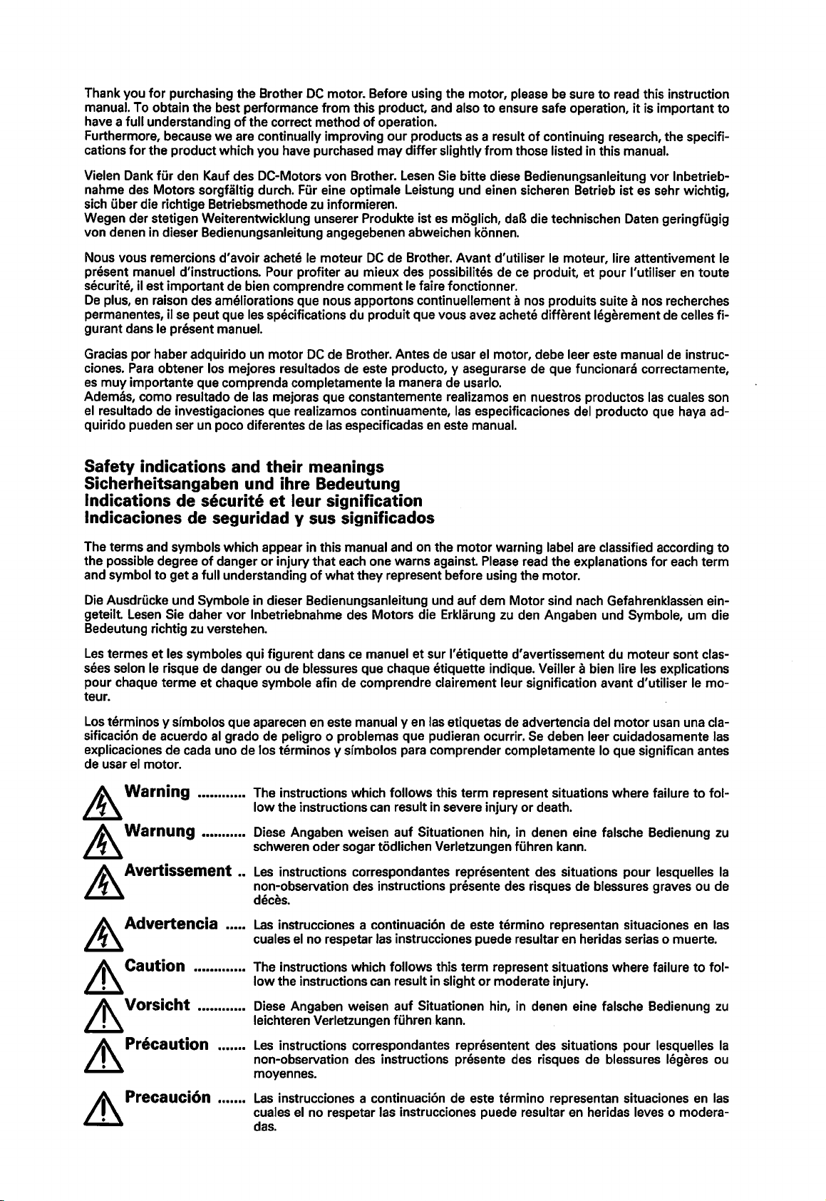
~Warning
~
~
~
~Caution
~
Lesen Sie daher
termes
chaque terme
zu
et
les symboles qui figurent dans
Warnung
Avertissement
Advertencia
Vorsicht
vor
verstehen.
et
•••••.•••••.
••••••••••.
••••••.•••••.
•••••.•••••.
lnbetriebnahme des Motors die Erklarung
ce
manuel et sur I' etiquette d'avertissement du moteur sont clas-
chaque symbole afin de comprendre clairement leur signification avant d'utiliser le
en
al
grado de peligro o problemas que pudieran ocurrir.
The instructions which follows this term represent situations where failure
low
the instructions can result in severe injury
Diese Angaben weisen auf Situationen hin, in denen eine falsche Bedienung
schweren oder sogar ted lichen Verletzungen fUhren kann.
Les
instructions correspondantes representant des situations
•.
non-observation des instructions presente des risques de blessures graves ou de
deces.
Las
••••.
instrucciones a continuaci6n de este termino representan situaciones en las
cuales
el
no respetar las instrucciones puede resultar en heridas serias o muerte.
The instructions which
low
the instructions can result in slight
Diese Angaben weisen auf Situationen hin, in denen eine falsche Bedienung
leichteren Verletzungen fuhren kann.
las etiquetas de advertencia del
follows this term represent situations where failure
Motor
sind nach GefahrenklassEm ein-
zu
den Angaben und Symbole, urn die
Se
or
death.
or
moderate injury.
deben leer cuidadosamente las
motor
pour
mo-
usan una cla-
to
fol-
zu
lesquelles
to
fol-
zu
Ia
Les
~Precaution
If\
Lll
Precauci6n
.......
instructions correspondantes representant des situations pour lesquelles
non-observation des instructions presente des risques de blessures legeres ou
moyennes.
Las
instrucciones a continuaci6n de este termino representan situaciones en las
cuales
el
das.
no respetar las instrucciones puede resultar
en
heridas leves o modera-
Ia
Page 3
Note
............................. The instructions which follows this term are supplementary instructions
erences which
should
be
read when using the machine.
or
ref-
Hinweis ....................... Diese Angaben sollten
Remarque
Nota
.............................
..................
Les
instructions correspondantes sont des instructions supplementaires ou des
references qu'il faut lire lorsqu'on utilise
Las
instrucciones a continuaci6n de este termino son instrucciones suplementa-
rias o referencias que
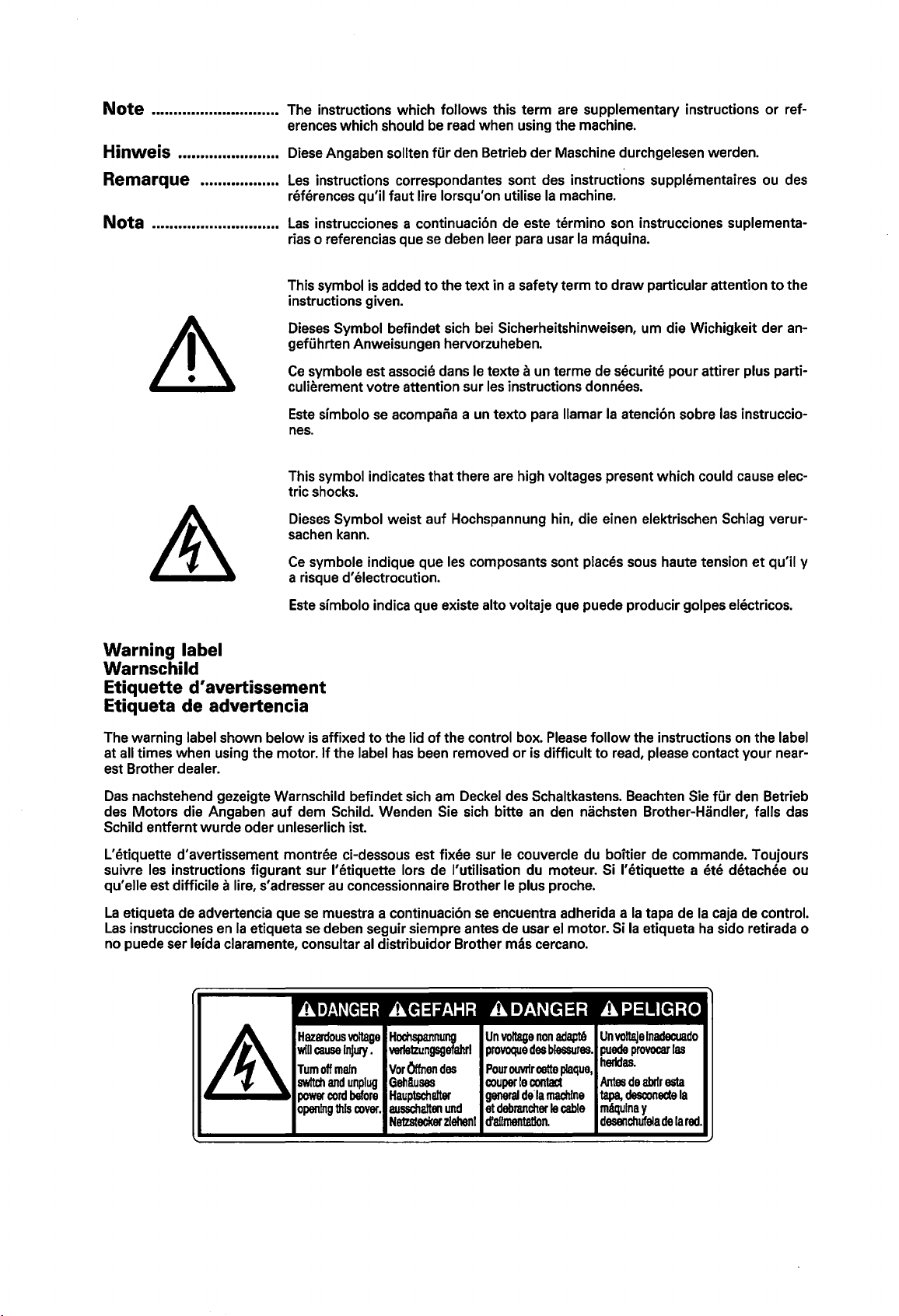
This symbol is added
instructions given.
Dieses
Symbol befindet sich bei Sicherheitshinweisen, urn die Wichigkeit der an-
gefuhrten Anweisungen hervorzuheben.
Ce
symbole est associe dans le texte a un terme de securite pour attirer plus parti-
culierement votre attention sur les instructions donnees.
Este
simbolo
nes.
This symbol indicates that there are high voltages present which could cause electric shocks.
Dieses
sachen kann.
Ce
symbole indique que les composants sont places sous haute tension
a risque
se
acompana a un texto para llamar
Symbol weist auf Hochspannung hin, die einen elektrischen Schlag verur-
d'
electrocution.
fur
den Betrieb der Maschine durchgelesen werden.
Ia
machine.
se
deben leer para usar
to
the text in a safety term
Ia
maquina.
to
draw
particular attention
Ia
atenci6n sobre las instruccio-
et
to
the
qu'il y
Este
simbolo indica que existe alto voltaje que puede producir golpes electricos.
Warning label
Warnschild
Etiquette
d'
avertissement
Etiqueta de advertencia
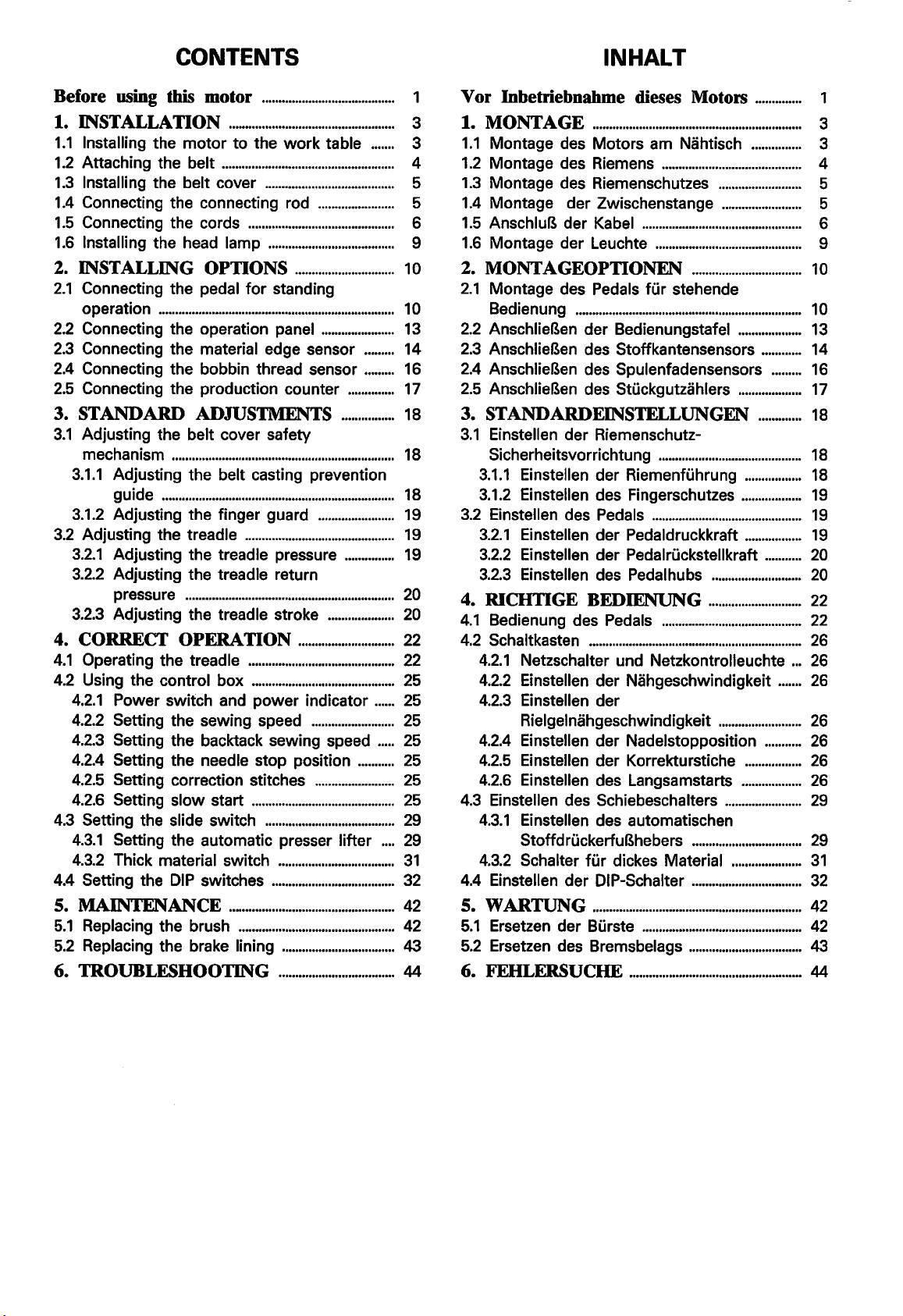
The warning label shown below is affixed
at all times when using the motor.
est Brother
Das
des Motors die Angaben auf dem
Schild entfernt
L'etiquette d'avertissement montree ci-dessous est
suivre
qu'elle est difficile a lire, s'adresser
La
etiqueta de advertencia que
Las
instrucciones
no puede ser
dealer.
nachstehend gezeigte Warnschild befindet sich am Deckel des Schaltkastens. Beachten Sie
wurde
oder unleserlich ist.
les instructions figurant sur !'etiquette lors de !'utilisation du moteur. Si !'etiquette a ete detachee ou
en
Ia
leida claramente, consultar
etiqueta
If
se
muestra a continuaci6n
se
ADANGER
Hazardous
will
cause
Tum
off
swltd'l
power
opening
to
the lid
of
the label
Schild. Wenden Sie sich bitte
au
deben seguir siempre antes de usar el motor. Si
has
concessionnaire Brother le plus proche.
al
distribuidor Brother mas cercano.
AGEFAHR
voltage
Hochspannung
InJury • verle1zungsgefahrl
main
and
cord
this
unplug
before
cover.
Vor
GehAuses
Hauptschafter
ausschalten
Ne1zstecker
the control box. Please
been removed
fixee sur le couvercle du boitier de commande. Toujours
or
is difficult
an
se
encuentra adherida a
ADANGER
Un
voltage
non
des
le
contact
de·
Ia
debrancher
Otrnen
des
und
zlehenl
provoque
Pourouvrlrcette
couper
general
et
d'allrnentatlon.
follow
to
read, please contact your near-
den nachsten Brother-Handler, falls das
APELIGRO
adapt6
Un
blessures.
plaque,
machine
le
cable
voftaJe
puede
hertdas.
Antes
tapa,
mtqulna
desenchufela
the instructions on the label
Ia
tapa de
Ia
etiqueta
lnadecuado
provocar
de
abrfr
desconecte
y
esta
de
las
Ia
Ia
ha
Ia
red.
fur
den Betrieb
caja de control.
sido retirada o
Page 4
CONTENTS
INHALT
Before using this motor
1. IN'STALLATION
1.1
Installing the
1.2
Attaching the belt
1.3
Installing the belt cover
1.4
Connecting the connecting rod
1.5
Connecting the cords
1.6
Installing the head lamp
motor
2. IN'STALLIN'G OPTIONS
2.1
Connecting the pedal
operation
2.2
Connecting the operation panel
2.3
Connecting the material edge sensor
2.4
Connecting the bobbin thread sensor
2.5
Connecting the production counter
.......................................................................
........................................
..................................................
to
the
work
....................................................
.......................................
.......................
............................................
......................................
..............................
for
standing
......................
3. STANDARD ADJUSTMENTS
3.1
Adjusting the belt cover safety
mechanism
3.1.1
Adjusting the belt casting prevention
guide
3.1.2
Adjusting the finger guard
3.2
Adjusting the treadle
3.2.1
Adjusting the treadle pressure
3.2.2
Adjusting the treadle return
pressure
3.2.3
Adjusting the treadle stroke
4. CORRECT OPERATION
4.1
Operating the treadle
4.2
Using the control box
4.2.1
Power switch and
4.2.2
Setting the sewing speed
4.2.3
Setting the backtack sewing speed
4.2.4
Setting the needle stop position
4.2.5
Setting correction stitches
4.2.6
Setting slow start
4.3
Setting the slide switch
4.3.1
Setting the automatic presser lifter
4.3.2
Thick material switch
4.4 Setting the
5. MAIN'TENANCE
5.1
Replacing the brush
5.2
Replacing the brake lining
6. TROUBLESHOOTIN'G
...................................................................
......................................................................
.......................
.............................................
...............................................................
.............................
............................................
...........................................
DIP
power
...........................................
switches
indicator
.........................
........................
.......................................
...................................
.....................................
..................................................
...............................................
..................................
...................................
table
.......
.........
.........
..............
................
...............
....................
......
.....
...........
....
1
Vor Inbetriebnahme dieses Motors
3
3
4
5
5
6
9
10
1 0 Bedienung
13
14
16
17
18
18
18
19
19
19
20
20
22
22
25
25
25
25
25
25
25
29
29
31
32
42
42
43
44 6. FEHLERSUCHE
1. MONTAGE
1.1
Montage des Motors am Nahtisch
1.2
Montage des Riemens
1.3
Montage des Riemenschutzes
1.4
Montage der Zwischenstange
1.5
AnschluB der Kabel
1.6
Montage der Leuchte
...............................................................
2. MONTAGEOPTIONEN
2.1
Montage des Pedals
....................................................................
2.2
AnschlieBen der Bedienungstafel
2.3
AnschlieBen des Stoffkantensensors
2.4
AnschlieBen des Spulenfadensensors
2.5
AnschlieBen des Stuckgutzahlers
3. STANDARDEIN'STELLUNGEN
3.1
Einstellen der RiemenschutzSicherheitsvorrichtung
3.1.1
Einstellen der Riemenfuhrung
3.1.2
Einstellen des Fingerschutzes
3.2
Einstellen des Pedals
3.2.1
Einstellen der Pedaldruckkraft
3.2.2
Einstellen der Pedalruckstellkraft
3.2.3
Einstellen des Pedalhubs
4. RICHTIGE BEDIENUNG
4.1
Bedienung des Pedals
4.2
Schaltkasten
4.2.1
Netzschalter und Netzkontrolleuchte
4.2.2
Einstellen der Nahgeschwindigkeit
4.2.3
Einstellen der
Rielgelnahgeschwindigkeit
4.2.4
Einstellen der Nadelstopposition
4.2.5
Einstellen der Korrekturstiche
4.2.6
Einstellen des Langsamstarts
4.3
Einstellen des Schiebeschalters
4.3.1
Einstellen des automatischen
StoffdruckerfuBhebers
4.3.2
Schalter
4.4
Einstellen der DIP-Schalter
5.
WARTUNG
5.1
Ersetzen der Burste
5.2
Ersetzen des Bremsbelags
................................................................
fur
dickes Material
...............................................................
..............
1
3
...............
..........................................
.........................
........................
................................................
............................................
.................................
fur
stehende
...................
............
.........
...................
.............
...........................................
.................
..................
.............................................
.................
...........
...........................
............................
..........................................
.........................
...........
.................
..................
.......................
.................................
.....................
.................................
................................................
..................................
....................................................
...
.......
3
4
5
5
6
9
10
10
13
14
16
17
18
18
18
19
19
19
20
20
22
22
26
26
26
26
26
26
26
29
29
31
32
42
42
43
44
Page 5
TABLE DES MATIERES
CONTENIDO
Avant d'utiliser
1. IN'STALLATION
1.1
Installation du moteur sur
travail
1.2
Fixation de
1.3
Installation du couvercle de courroie
1.4
Branchement de
1.5
Branchement des cordons
1.6
Installation de !'ampoule de tete de
machine
..............................................................................
ce
moteur
..................................
..................................................
Ia
table de
Ia
courroie
.........................................................................
..........................................
Ia
tige de connexion
..................................
2. INSTALLATION DES OPTIONS
2.1
Branchement de
I' utilisation de bout
2.2
Branchement du panneau de
commande
2.3
Branchement du detecteur
.................................................................................
tissu
2.4
Branchement du detecteur
canette
2.5
Branchement du compteur de pieces
produites
............................................................................
.......................................................................
3. REGLAGES STANDARD
3.1
Reglage du dispositif de securite du
couvercle de courroie
3.1.1
Reglage du guide de prevention de
saute de courroie
3.1.2
Reglage
3.2
Reglage
3.2.1
3.2.2
3.2.3
4.
FONCI10NNEMENT CORRECT
4.1
Fonctionnement
4.2
Utilisation du boitier de commande
4.2.1
4.2.2
4.2.3
4.2.4
4.2.5
4.2.6
4.3
Reglage de l'interrupteur coulissant
4.3.1
4.3.2
4.4
Reglage des interrupteurs
s.
EN'TRETIEN"
5.1
Remplacement du balai
5.2
Remplacement de
6. GUIDE
de
Reglage
Reglage
pedale
Reglage de
lnterrupteur d'alimentation et temoin
d'alimentation
Reglage de
Reglage de
points d'arret
Reglage
l'aiguille
Reglage des points de correction
Reglage du debut de couture a
vitesse lente
Reglage du releveur de pied presseur
automatique
lnterrupteur pour tissu epais
DU
Ia
pedale pour
...................................................
...................................................................
de
bards du
de
fil de
...........................
...........................................
...........................................
du protege-doigts
Ia
pedale
de
de
....................................................................
de
................................................................
.............................................
Ia
pression de pedale
Ia
pression de retour de
Ia
course de pedale
de
Ia
pedale
...................................................
Ia
vitesse de couture
Ia
vitesse de couture des
.....................................................
Ia
position d'arret de
.......................................................
.......................................................
.......................
...........................
.............
...................
DIP
.........................
.............................................................
.......................................
Ia
garniture de frein
DEPANNAGE
.......................
..........
........
........
.......
...........
.........
.........
.........
.............
.....
2
3
3
4
5
5
6
9
10
10
13
14
16
17
18
18
18
19
19
19
20
20
21
21
27
27
27
27
27
27
27
30
30
31
33
42
42
43
44
Antes de usar este motor
1. IN'STALACION
1.1
lnstalacion del motor
trabajo
1.2
lnstalacion de
1.3
lnstalacion de
1.4
Conexion de
1.5
Conexion de los cables
1.6
lnstalacion de
............................................................................
.....................................................
Ia
correa
Ia
cubierta de
Ia
biela
Ia
luz
...................................
en
Ia
mesa
de
........................................
Ia
correa
..............................................
........................................
...............................................
2. OPCIONES DE INSTALACION
2.1
Conexion del pedal para operar de pie
2.2
Conexion del panel de control
2.3
Conexion del sensor de borde de
material
2.4
Conexion del sensor de hilo de bobina
2.5
Conexion del contador de produccion
..........................................................................
3. AJUS1ES ESTANDAR
3.1
Ajuste del mecanisme de seguridad de
Ia
cubierta
3.1.1
Ajuste de
salida de
3.1.2
Ajuste de
3.2
Ajuste del pedal
3.2.1
Ajuste de
3.2.2
Ajuste de
pedal
3.2.3
Ajuste del recorrido del pedal
4.
FUNCIONAMIENTO CORRECTO
4.1
Uso del pedal
4.2
Uso de
4.2.1
Interrupter principal e indicador de
alimentacion
4.2.2
Ajuste de
4.2.3
Ajuste de
4.2.4
Ajuste de
aguja
4.2.5
Ajuste de las puntadas de
correccion
4.2.6
Ajuste de comienzo Iento
4.3
Ajuste del interrupter de deslizamiento
4.3.1
Ajuste del levantador automatico del
prensatelas
4.3.2
Interrupter de material grueso
4.4
Ajuste
5.
MANTENIMIENTO
5.1
Cambia del cepillo
5.2
Cambia del forro de frena
de
Ia
correa
Ia
gufa
Ia
correa
Ia
proteccion para dedos
.......................................................
Ia
presion del pedal
Ia
presion de retorno del
......................................................................
.............................................................
Ia
caja
de controles
.......................................................
Ia
velocidad de costura
Ia
velocidad de rematado
Ia
posicion de parada de
......................................................................
............................................................
.........................................................
de
los interruptores
........................................
de prevencion de
.........................................
...........................................
..................................................
........................
..................................
...............
................
..............................
.........................
...............
DIP
.......................
.................................
6. LOCALIZACION DE A VERIAS
.......
..........
.....
.....
........
....
.....
.......
..
Ia
.....
.........
2
3
3
4
5
5
6
9
10
10
13
14
16
17
18
18
18
19
19
19
20
20
21
21
28
28
28
28
28
28
28
30
30
31
33
42
42
43
44
Page 6
Before using this motor
1.
Because the
moving
2.
Turn
off
there are no loose
3.
Turn
off
4.
If
you are using the three-phase motor, always
secure ground.
5.
Be
sure
sewing machine and before threading the needle.
6.
Wait at least
trol box.
does not drop immediately after the power switch is turned off.
7.
The control dials inside the control box have been pre-adjusted and should not
any circumstances.
8.
Do not use the motor near a strong source
correct operation
motor
it
from the work table.
the power switch before connecting and disconnecting any
the power switch when not using the motor.
to
turn
10
It
is dangerous
is
heavy, more than one person should be present when installing
or
disconnected connectors before turning the power switch back on again.
be
sure
to
connect the ground wire (green wire) to a
off
the power switch before raising the machine head
minutes after turning
to
open the face plate straight away,
of
the
motor
could result.
off
the power switch before opening the face plate
as
the voltage inside the control box
of
noise such
as
a high-frequency welder, otherwise in-
it
to and re-
of
the connectors. Check that
to
make adjustments
of
the con-
be
touched under
Vor lnbetriebnahme dieses Motors
1.
Wegen des groBen Gewichts sind zwei Personen notwendig, um den
vom
ren oder
2.
Vor dem AnschlieBen und Losen von Steckern muB die Stromversorgung ausgeschaltet werden.
Kontrollieren
angeschlossen sind.
3.
Schalten Sie die Stromversorgung aus, wenn der
4.
Bei
einem Dreiphasenmotor mussen Sie kontrollieren, ob das Erdungskabel (grunes Kabel) richtig
der Masse angeschlossen ist.
5.
Fur Einstellungen bei angehobenem Nahmaschinenoberteil oder zum Einfadeln muB der Netzschal-
ter
ausgeschaltet werden.
6.
Zum Qffnen der Stirnplatte des Schaltkastens muB nach dem Ausschalten des Netzschalters minde-
10
stens
schalters geoffnet wird, ist im Schaltkasten immer noch Spannung vorhanden.
7.
Die Regier im Schaltkasten sind voreingestellt und durfen unter keinen Umstanden beruhrt werden.
8.
Verwenden Sie den
quenzschweiBgerates, weil sonst Betriebsstorungen auftreten konnen.
Nahtisch abzunehmen.
Sie
vor
dem Wiedereinschalten der Stromversorgung, ob aile Stecker richtig und fest
Motor
nicht verwendet wird.
Minuten gewartet werden. Falls die Stirn platte unmittelbar nach dem Ausschalten des Netz-
Motor
nicht in der Nahe von starken Storsignalquellen, wie
Motor
am
Nahtisch
z.B.
eines Hochfre-
zu
montie-
to
the
an
-
1-
Page 7
Avant d'utiliser ce moteur
1.
Le
moteur etant lourd, le concours de plusieurs personnes est necessaire pour !'installer
lever de
2. Mettre l'interrupteur d'alimentation sur
quelconque des connecteurs. Verifier que tous les connecteurs sont bien fermement branches avant
de remettre l'interrupteur d'alimentation sur
3. Mettre l'interrupteur d'alimentation sur
4.
Si
une borne de terre appropriee.
5.
Veiller a toujours mettre l'interrupteur d'alimentation sur
de machine pour faire des reglages sur
6.
Attendre
avant d'ouvrir
immediatement, car
ment
7.
Les
solument pas
8.
Ne
quence, sinon
Ia
table de travail.
Ia
position d'arret avant de brancher ou de debrancher l'un
Ia
position demarche.
Ia
position d'arret lorsqu'on n'utilise pas le moteur.
I' on utilise un moteur triphase, veiller a toujours brancher le cable de mise a
Ia
position d'arret avant de soulever
Ia
machine a coudre et avant d'enfiler l'aiguille.
au
mains 10 minutes
Ia
plaque frontale du boitier de commande.ll est dangereux d'ouvrir
Ia
tension presente dans le boitier de commande ne disparait
apres qu'on ait mis l'interrupteur d'alimentation sur
commandes situees dans le boitier de commande ont ete prereglees
etre touchees.
pas
utiliser le moteur pres d'une forte source de bruit telle qu'un appareil de soudure a haute fre-
le
moteur pourrait presenter des anomalies de fonctionnement.
apn3s
avoir mis l'interrupteur d'alimentation sur
Ia
position d'arret.
en
usine et
Ia
et
pour I' en-
terre (cable vert) a
Ia
position d'arret
Ia
plaque frontale
pas
immediate-
ne
doivent ab-
Ia
tete
Antes de
1.
Debido a que el
zar con
2.
Apagar
nectores no hayan quedado desconectados o flojos antes de volver a encender el interrupter principal.
3. Apagar
4.
AI usar un motor trifasico,
tierra segura.
5.
Asegurarse de apagar
Ia
6.
Esperar
tera de
que
terrupter principal.
7.
Los
ninguna circunstancia.
8.
No usar
cuencia, o de lo contrario
Ia
ayuda de mas de una persona.
el
interrupter principal antes de conectar o desconectar los conectores. Verificar que los co-
el
interrupter principal cuando
maquina de coser y antes de enhebrar
al
menos 10 minutes despues de apagar
Ia
caja de controles.
el
voltaje
diales de control dentro de
el
motor cerca de una fuente de ruido fuerte como una aparato de soldadura de alta fre-
usar
motor
es
pesado,
se
el
interrupter principal antes de levantar
en
Ia
caja de controles no
el
motor pod
este motor
Ia
instalaci6n y
nose
debe conectar siempre
Ia
Es
peligroso abrir
se
Ia
caja de controles han sido preajustados y no
ria
no funcionar correctamente.
el
desmontaje de
use
el
motor.
el
cable a tierra (cable verde) en una conexi6n a
Ia
aguja.
el
interrupter principal antes de abrir
Ia
placa delantera directamente hacia afuera, debido a
interrumpe inmediatamente despues que
Ia
mesa de trabajo
cabeza de
Ia
se
debe reali-
maquina para ajustar
Ia
placa delan-
se
apaga el in-
se
deben tocar bajo
-2-
Page 8
1. INSTALLATION
1. INSTALLATION
1. MONTAGE
1.1
Installing
1.1
Montage
1.1
Installation
1.1
lnstalaci6n del
the
motor
des
Motors
du
moteur
motor
1
~-
I
to
the
work
am
Nihtisch
sur Ia
table
en Ia mesa de
table
de
trabajo
1. INSTALACION
travail
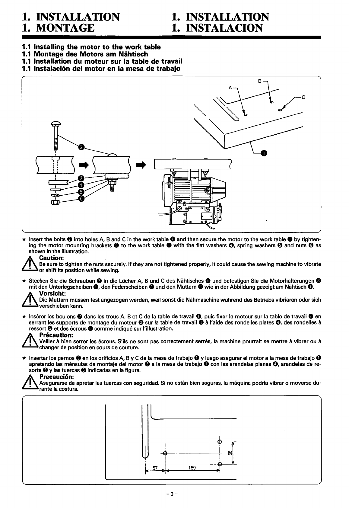
* Insert the bolts 8 into holes A, B and C in the
ing the
shown in the illustration.
motor
mounting brackets e
Caution: .
Be
sure to tighten the
or
shift its position while sewing.
f!Uts
to
securely.
the
work
If
they are
work
table 0 and then secure the
table 0
not
with
the
tightened properly,
flat
motor
to
the
washers
8,
spring washers e and nuts
it
could cause the sewing machine
work
table 0 by tighten-
to
vibrate
Cit
as
* Stecken Sie die Schrauben 8 in die Locher A, B und C des Nahtisches 0 und befestigen Sie die Motorhalterungen e
mit
den Unterlegscheiben
Vorsicht:
Die Muttern mussen fest angezogen werden, weil sonst die Nahmaschine wahrend des Betriebs vibrieren oder sich
verschieben kann.
* lnserer les boulons 8 dans les trous A, B
serrant les supports de montage du moteur e sur
ressort e
&
• changer de position
* lnsertar los pernos 8 en los orificios A, B y C de
apretando las mensulas de montaje del
sorte
&
et
des ecrous
Precaution:
Veiller a bien serrer les ecrous. S'ils ne sont pas correctement serres,
8 y las tuercas
Precauci6n:
Asegurarse de apretar las tuercas con seguridad. Si no estan bien seguras,
rante
Ia
costura.
8,
den Federscheiben e und den Muttern
et
C de
Cit
com me indique sur !'illustration.
en
cours de couture.
ct
indicadas
en
Ia
figura.
motor
Cit
wie
in der Abbildung gezeigt am Nahtisch
Ia
table de travail
Ia
table de travail 0 a I' aide des rondelles plates
Ia
mesa de trabajo 0 y luego asegurar el
e a
Ia
mesa de trabajo 0 con las arandelas planas
0,
puis fixer le moteur sur
Ia
machine pourrait se mettre a vibrer ou a
Ia
maquina podria vibrar o moverse
Ia
table de travail 0
motor a Ia
0.
8,
des rondelles a
mesa de trabajo 0
8,
arandelas de re-
en
du-
l
~
--
--
~
~
.J'
I
r---
-E
~
~
-3-
159
I
I
I
(0
(0
~
Page 9
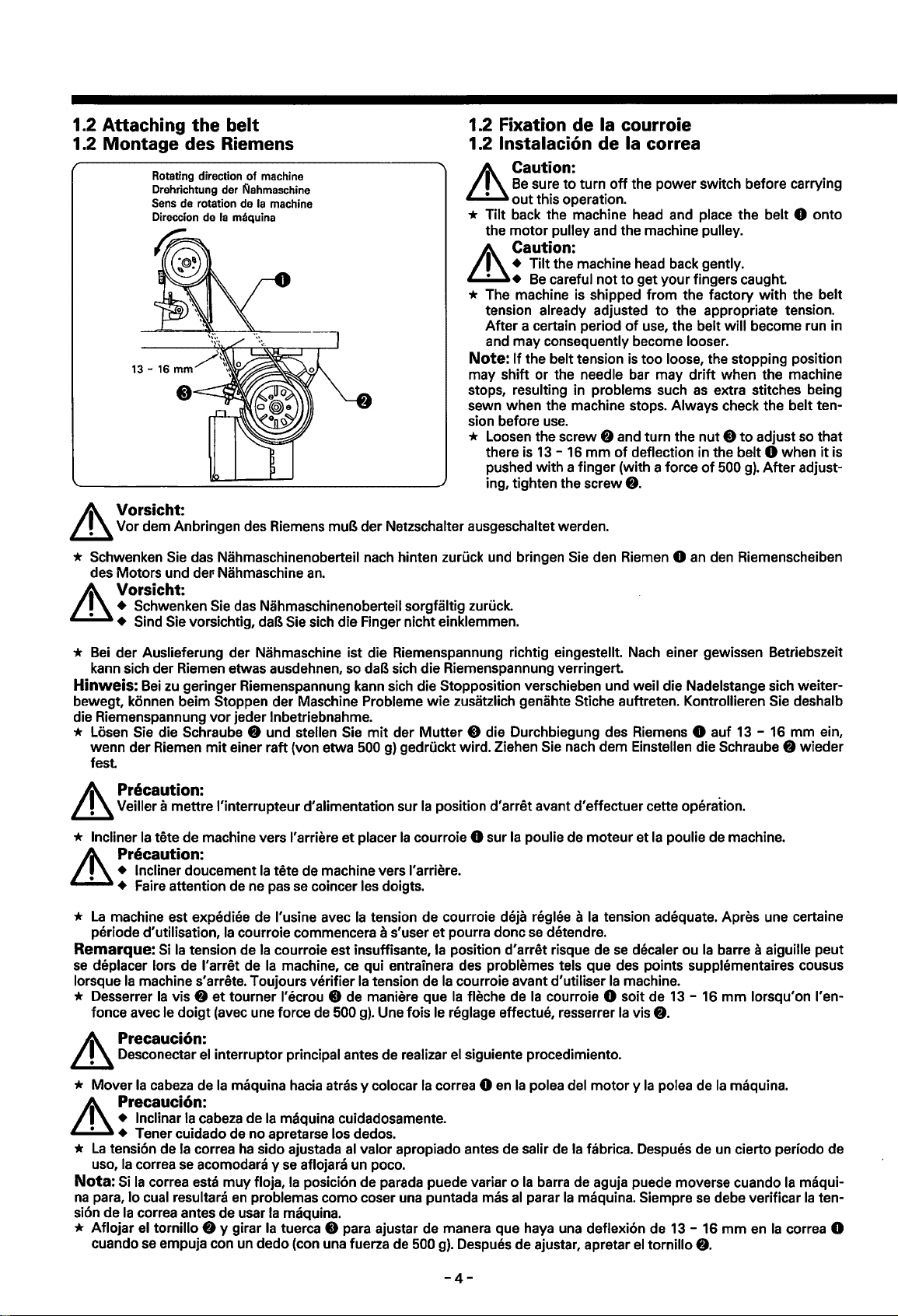
1.2 Attaching the belt
1.2 Montage des Riemens
Rotating direction
Drehrichtung der
de rotation de
Sens
Direccion de
of
l\lahmaschine
Ia
maquina
machine
Ia
machine
~
A\ Vorsicht:
~
Vor dem Anbringen des Riemens muB
1.2 Fixation de Ia courroie
1.2 lnstalaci6n de
Caution:
Be
&
sure
out
this operation.
* Tilt back the machine head and place the belt 0 onto
the
motor
Caution:
+ Tilt the machine head back gently.
•
Be
* The machine is shipped
tension already adjusted
After
a certain period
and may consequently become looser.
Note:
If
may shift or the needle bar may
stops, resulting in problems such
sewn when the machine stops. Always check the
sion before
* Loosen the screw
der
Netzschalter ausgeschaltet werden.
the belt tension is
use.
there is
pushed
ing, tighten the screw
13-
with
Ia correa
to
turn
off
the power switch before carrying
pulley and the machine pulley.
careful
not
to
get your fingers caught.
from
the factory
to
of
f)
16
a finger (with a force
and turn the
mm
of
the appropriate tension.
use, the belt will become run in
too
loose, the stopping position
drift
deflection in the belt 0 when
when the machine
as
extra stitches being
nut 8 to
of
500
8.
with
the belt
belt ten-
adjust so that
g).
After
adjust-
it
is
* Schwenken Sie das Nahmaschinenoberteil nach hinten zuruck und bringen Sie den Riemen 0
des Motors und
der Nahmaschine
Vorsicht:
• Schwenken Sie das Nahmaschinenoberteil sorgfaltig zuruck.
• • Sind Sie vorsichtig, daB Sie sich die Finger nicht einklemmen.
*
Bei
der Auslieferung der Nahmaschine ist die Riemenspannung richtig eingestellt. Nach einer gewissen Betriebszeit
kann sich der Riemen etwas ausdehnen, so
Hinweis:
bewegt, konnen beim
die Riemenspannung
* Losen Sie die Schraube
wenn der Riemen
fest
Bei
zu
geringer Riemenspannung kann sich die Stopposition verschieben und weil die Nadelstange sich weiter-
Stoppen der Maschine Problema
vor
jeder lnbetriebnahme.
f)
mit
einer raft (von etwa 500
an.
und stellen Sie
daB sich die Riemenspannung verringert.
wie
zusatzlich genahte Stiche auftreten. Kontrollieren Sie deshalb
mit
der
Mutter
g)
gedruckt wird. Ziehen Sie nach dem Einstellen die Schraube
8 die Durchbiegung des Riemens 0 auf
A\ Precaution:
~
Veiller a mettre l'interrupteur d'alimentation sur
* Incliner
Ia
tete de machine vers l'arriere
et
placer
Precaution:
&
• Incliner doucement
• + Faire attention de ne pas se coincer les doigts.
*
La
machine est expediee de l'usine avec
periode
Remarque:
se
deplacer lors de l'arret de
lorsque
* Desserrer
fonce avec
d'utilisation,
Si
Ia
tension de
Ia
machine s'arrete. Toujours verifier
Ia
vis
f)
et
le
doigt
Ia
tete de machine vers l'arriere.
Ia
Ia
courroie commencera a s'user
Ia
courroie est insuffisante,
Ia
machine,
tourner l'ecrou 0 de maniere que
(avec une force de 500
tension de courroie deja reglee a
ce
qui entrainera des problemas tels que des points supplementaires cousus
Ia
tension de
g).
Ia
position d'arret avant d'effectuer cette operation.
Ia
courroie 0 sur
et
pourra done
Ia
position d'arret risque de
Ia
courroie avant d'utiliser
Ia
Une fois le reglage effectue, resserrer
Ia
fleche de
poulie de moteur et
Ia
se
detendre.
Ia
courroie 0 soit de
tension adequate. Apres une certaine
se
decaler ou
Ia
machine.
Ia
vis
Ia
poulie de machine.
f).
an
den Riemenscheiben
13-
Ia
barre a aiguille peut
13-
16
mm
lorsqu'on l'en-
16
mm
f)
wieder
ein,
A\ Precauci6n:
~
Desconectar el interruptor principal antes de realizar el siguiente procedimiento.
* Mover
Ia
cabeza de
Ia
maquina hacia atras y colocar
Ia
correa 0
en
Ia
Precauci6n:
+ lnclinar
• Tener cuidado de no apretarse los dedos.
*
La
tension de
uso,
Ia
correa
Nota: Si
na
sion de
* Aflojar
Ia
para, lo cual resultara
Ia
correa antes de usar
el
cuando
Ia
cabeza de
Ia
correa
se
acomodara y
correa esta
tornillo
se
f)
empuja con un dedo (con una fuerza de 500
Ia
maquina cuidadosamente.
ha
sido ajustada al valor apropiado antes de salir de
se
aflojara un poco.
muy
floja,
Ia
en
problemas como coser una puntada mas
y girar
posicion de parada puede variar o
Ia
maquina.
Ia
tuerca 8 para ajustar de manera que haya una deflexion de 13 - 16
Ia
al
g).
Despues de ajustar, apretar
-4-
polea del
barra de aguja puede moverse cuando
parar
Ia
motor y Ia
Ia
fabrica. Despues de un cierto periodo de
maquina. Siempre
el
tornillo
polea de
se
f).
Ia
maquina.
en
Ia
Ia
correa 0
debe verificar
mm
maqui-
Ia
ten-
Page 10
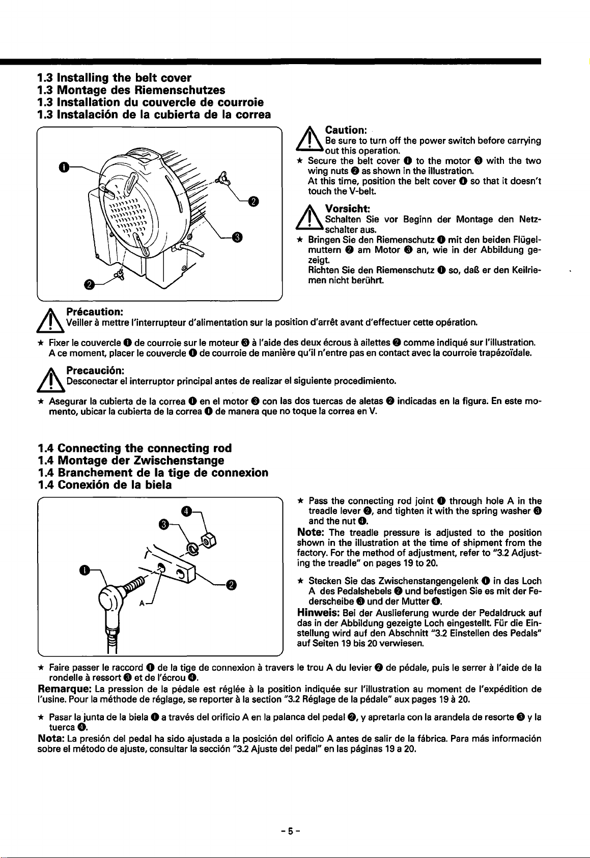
1.3 Installing
the
belt
cover
1.3 Montage des Riemenschutzes
Installation du couvercle de courroie
1.3
lnstalaci6n de Ia cubierta de Ia correa
1.3
A\
Caution: .
L.!.1
Be
sure
to
turn
off
out
this operation.
* Secure the belt cover 0 to the
wing nuts 8
At
this time, position the belt cover 0
touch the V-belt.
as
shown in the illustration.
the power switch before carrying
motor
8 with the
so
that
it
doesn't
two
Vorsicht:
A\
L.!.1
Precaution:
Veiller a mettre l'interrupteur d'alimentation sur
Schalten
&
schalter
* Bringen Sie den Riemenschutz 0
muttern 8 am Motor 8
zeigt.
Richten
men nicht beruhrt.
Ia
position d'arret avant d'effectuer cette operation.
Sie
vor
Beginn der Montage den Netz-
aus.
an,
Sie den Riemenschutz 0 so,
mit
wie in der Abbildung ge-
den beiden Flugel-
daB
er den Keilrie-
* Fixer le couvercle 0 de courroie sur le moteur 8 a I' aide des deux ecrous a ailettes 8 comma indique sur !'illustration.
Ace
A\
L.!.1
moment, placer le couvercle 0 de courroie de maniere qu'il n'entre pas
Precauci6n:
Desconectar el interrupter principal antes de realizar
el
siguiente procedimiento.
en
contact avec
Ia
courroie trapezo'idale.
* Asegurar
mento, ubicar
1.4 Connecting
1.4 Montage
Ia
cubierta de
Ia
cubierta de
der
the
Zwischenstange
1.4 Branchement de
1.4 Conexi6n
* Faire passer
rondelle a ressort e
Remarque:
l'usine. Pour
de
Ia biela
le
raccord 0 de
et
La
pression de
Ia
methode de reglage,
Ia
correa 0 en el
Ia
correa 0 de manera que no toque
connecting rod
Ia
tige
de connexion
Ia
de l'ecrou
tige de connexion a travers
8.
Ia
pedale est reglee a
se
reporter a
motor
8 con las dos tuercas de aletas 8 indicadas
Ia
correa
*
Pass
the connecting rod joint 0 through hole A in the
treadle lever
and the
en
nut8.
V.
8,
Note: The treadle pressure is adjusted
shown in the illustration at the time
factory. For the method
ing the
treadle" on pages
* Stecken Sie das Zwischenstangengelenk 0 in das Loch
A des Pedalshebels 8 und befestigen
derscheibe 8 und der Mutter
Hinweis:
das
stellung
auf Seiten
le
trou A du levier 8 de pedale, puis
Ia
position indiquee sur !'illustration
Ia
section "3.2 Reglage de
Bei
in
der Abbildung gezeigte Loch eingestellt. Fur die Ein-
der Auslieferung wurde der Pedaldruck auf
wird
auf den Abschnitt "3.2 Einstellen des Pedals"
19
bis
20
Ia
pedale" aux pages
and tighten
of
adjustment, refer
19
to
verwiesen.
au
en
Ia
figura;
En
este me-
it
with
the spring washer 8
to
of
20.
8.
le
moment de !'expedition de
19 a 20.
the position
shipment from the
to
"3.2 Adjust-
Sie
es
mit
der
Fe-
serrer a l'aide
de
Ia
*
Pasar
Ia
junta de
tuerca
8.
Nota:
La
sobre el metodo de ajuste, consultar
presion del pedal
Ia
biela 0 a traves del orificio A
ha
sido ajustada a
Ia
seccion "3.2 Ajuste del pedal"
en
Ia
palanca del pedal
Ia
posicion del orificio A antes de salir de
-5-
8,
en
las paginas
y apretarla con
Ia
19 a 20.
Ia
arandela de resorte 8 y
fabrics.
Para
mas informacion
Ia
Page 11
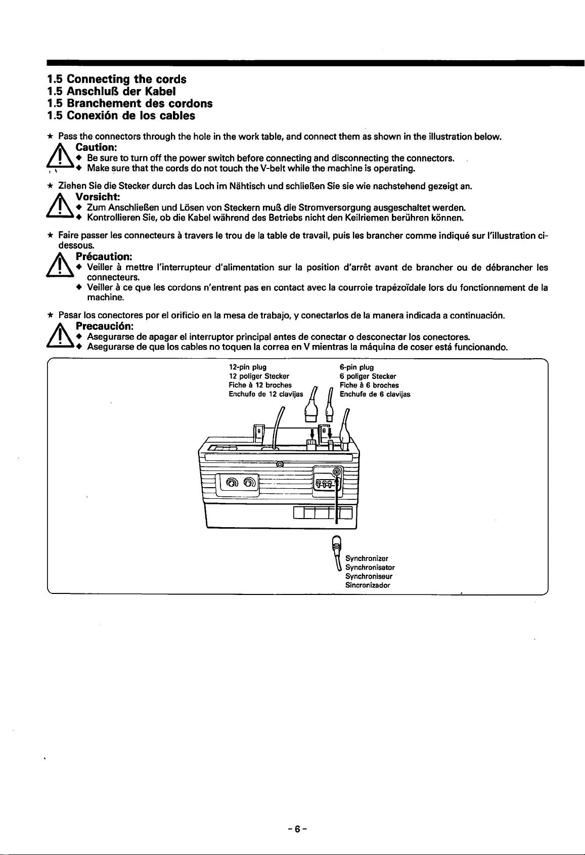
1.5 Connecting
the
cords
1.5 AnschluB der Kabel
1.5 Branchement des cordons
1.5 Conexi6n de los cables
*
Pass
the connectors through the hole in the
A\_
Caution:
~
•
Be
sure
to
turn
off
the
, , • + Make sure
that
power
the cords
do
not
work
table, and connect them
switch before connecting and disconnecting the connectors.
touch the V-belt while the machine is operating.
as
shown in the illustration below.
* Ziehen Sie die Stecker durch das Loch
Vorsicht:
&
+ Zum AnschlieBen und Losen von Steckern muB die Stromversorgung ausgeschaltet werden.
+ Kontrollieren Sie,
ob
die Kabel wahrend des Betriebs nicht den Keilriemen beriihren konnen.
im
Nahtisch und schlieBen Sie sie
* Faire passer les connecteurs a travers le trou de
dessous.
Precaution:
• Veiller a mettre l'interrupteur d'alimentation sur
connecteurs.
+ Veiller
* Pasar los conectores
Precauci6n:
• Asegurarse de apagar
• Asegurarse de que los cables no toquen
ace
machine.
que
por
Jes
cordons n'entrent pas en contact avec
el orificio
en
Ia
mesa de trabajo, y conectarlos de
el
interruptor principal antes de conectar o desconectar los conectores.
Ia
table de travail, puis
Ia
position d'arret avant de brancher ou de debrancher
Ia
correa en V mientras
wie
nachstehend gezeigt
Jes
brancher comme indique
Ia
courroie trapezoi"dale tors du fonctionnement de
Ia
man era indicada a continuaci6n.
Ia
maquina de coser esta funcionando.
6-pin plug
6 poliger Stecker
a 6 broches
Rche
Enchufe de 6
clavijas
an.
sur
l'illustration ci-
Jes
Ia
~
Synchronizer
~
Synchronisator
Synchroniseur
Sincronizador
-6-
Page 12

A\ Caution:
~
+ ·Refer
+ Terminal <Dis the
+ Solenoids and
is necessary
• Never short terminals
Vorsicht:
&
+ Fur die Zusatzausgangsfunktion
• Die Klemme
+ Falls Solenoide oder ein Luftventil angeschlossen warden, mussen sie einen Widerstand von mindestens 10Q
aufweisen. AuBerdem
die Nennspannung einzustellen.
• Die Klemmen
12-pin plug
12 poliger
Fiche a 12 broches
Enchufe de
to
4.4
"DIP switch settin9s" on page 32
power
an
to
connect serial resistors
<D
ist
<D
und ® durfen niemals kurzgeschlossen warden, weil sonst
terminal (approx.
air valve can be connected,
<D
and
®,
die Stromversorgung
ist
es notwendig Serienwiderstande am Luftventil anzuschlieBen, urn die Spannung
Connecteur
Enchufe de 12 clavijas
Stecker
12
clavijas
for
+42
but
to
the air valve so that the voltage is at the rated voltage.
as
this will damage the motor.
wird
auf
den Abschnitt ,4.4 DIP-Schalter-Einstellungen"
(ca.
+42
Thread
Fadenabschneidersolenoid
Soleno'ide de coupe du fil
Solenoide del cortahilos
Thread
Fadenwischersolenoid
Soleno'ide
Solenoide
Option
Zusatzausgang (positive Seite)
Sortie
Salida
Option
Zusatzausgang
Sortie
Salida opcional (lado
details
V)
and terminal
they
V)
und die Klemme ® ist die
12-pin connector
12poliger
Stecker
trimming
wiping
du
output
d'option
opcional (lado
output(-
d'option
of
the option
a
12
broches
solenoid
solenoid
tire-fil
dellimpiahilos
(+
side)
(cOte+)
+)
side)
(negative
Seite)
(c6te
-)
-)
output
®is
the transistor collector terminal.
should have resistances
No. 12-pin connector
Nr. 12poliger
No. Connecteur a
No. Enchufe de 12 clavijas
Reverse solenoid
Umkehrsolenoid
®·®
Solenoide
Solenoide
Reverse switch
Umkehrschalter
CD·®
lnterrupteur
Interrupter de marcha atras
Ground
Masse
(i)
Terre
Tierra
Spare
Frei
®
Rechange
Libra
Stecker
12
broches
de
couture arrit3re
de marcha atras
de
couture arriere
No.
Nr.
No.
No.
®·®
®·®.
®
®
function.
of
10 Q or
Transistorkollektorklemme~
greater. In addition,
auf
Seite 32 verwiesen.
it
auf
der
Motor
beschadigt warden kann.
Precaution:
&
+ Pour plus de details concernant
• teurs DIP" a
+
La
borne (j) est
+
Les
soleno'ides
Q ou plus.
Ia
valeur nominate.
+ Ne jamais court-circuiter les barnes
Precauci6n:
&
+ Consultar
salida opcional.
+ Terminal <Des
• Se pueden conectar solenoides y valvulas de aire, pero debe tener resistencias de
necesario conectar resistencias
• Nunca cortocircuitar los terminates
Ia
page
33.
Ia
borne d'alimentation (environ
et
une soupape d'air peuvent etre branchees, mais elles doivent etre munies de resistances de 10
De
plus; il
faut
brancher des resistances serielles a
Ia
secci6n
4.4
"Ajuste de los interruptores DIP" en
el
terminal de alimentaci6n (aprox.
en
Ia
fonction de sortie
+42V)
<D
et
®,
sinon le
+42
serie a
Ia
<D
valvula de aire de manera que
y
®,
pues esto podrla daiiar el motor.
d'
option, se reporter a
et
Ia
moteur
V)
y
terminal®
borne®
sera endommage.
Ia
soupape
Ia
pagina 33
est
es
Ia
section
Ia
borne du collecteur a transistor.
d'air
por
4.4
"Reglage des interrup-
afin que
Ia
tension corresponde a
mas detalles sabre
Ia
funci6n de
el terminal del colector del transistor.
10
Q o mayores. Ademas, es
el
voltaje
sea
igual
al
voltaje nominal.
-7-
Page 13
6-pin plug
6 poliger Stecker
Fiche a 6 broches
Enchufe de 6
clavijas
6-pin connector
6poliger Stecker
Connecteur a 6 broches
Conector de 6 clavijas
Presser
lifter solenoid
StoffdruckerfuBhebersolenoid
Solenoi"de de releveur de
pied presseur
Solenoide dellevantador del
prensatelas
Option (air)
Option (Luft)
Option (air)
Opcional (aire)
6-pin connector No.
No.
Nr.
6poliger Stecker
No.
Connecteur a 6 broches
Conector de 6 clavijas No.
No.
Knee switch
Knieschalter
CD·®
lnterrupteur au genou
Interrupter de rodilla
Ground
Masse
®
Terre
Tierra
Nr.
No.
®·®
®
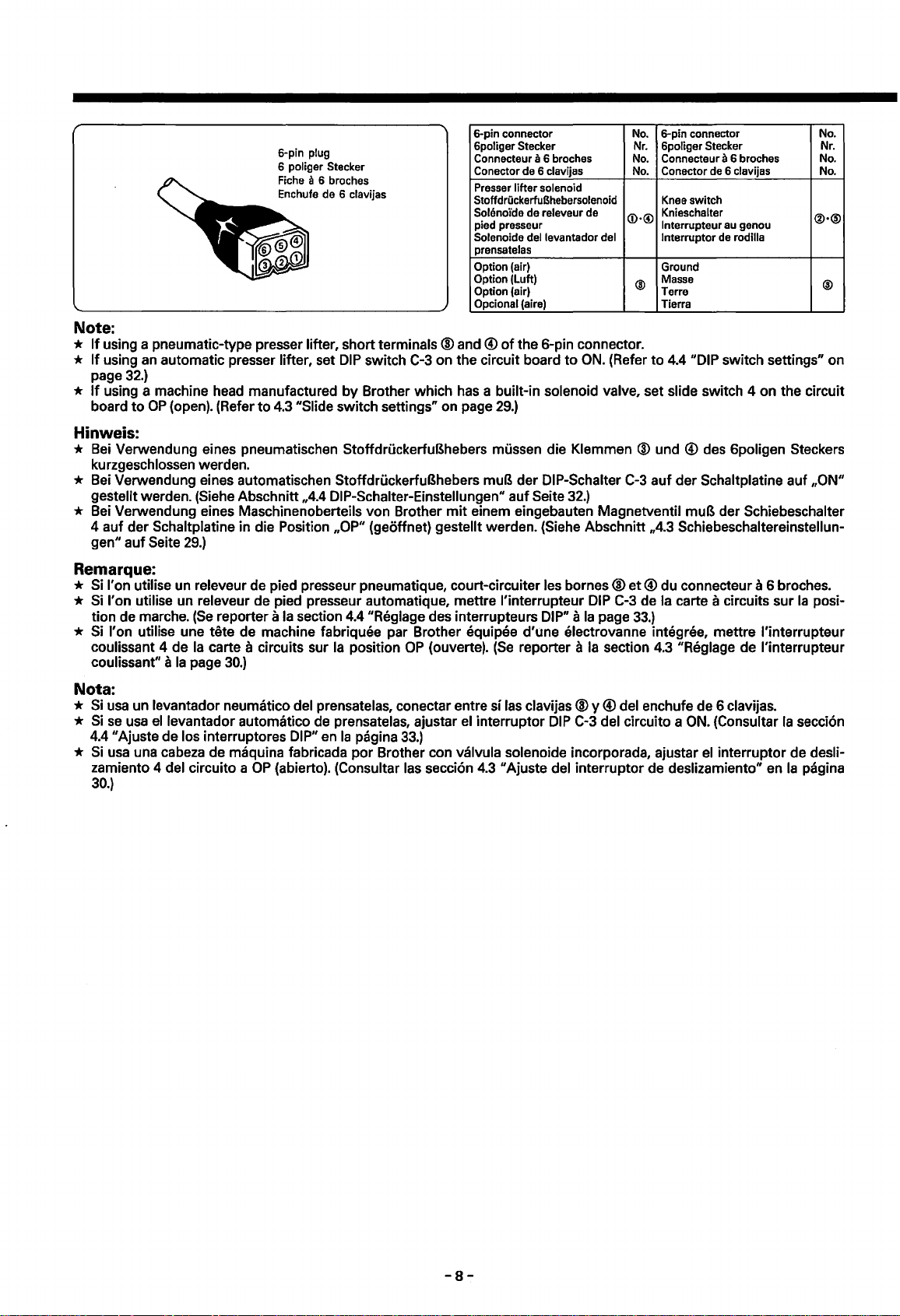
Note:
*
If
using a pneumatic-type presser lifter, short terminals @ and ®
*
If
using
an
page
*
If
using a machine head manufactured by Brother which has a built-in solenoid valve, set slide switch 4 on the circuit
board
automatic presser lifter, set
32.)
to
OP
(open). (Refer
to
4.3
DIP
switch C-3 on the circuit board
"Slide switch settings" on page
of
the 6-pin connector.
to
ON.
29.)
(Refer
to
4.4
"DIP switch settings" on
Hinweis:
*
Bei
Verwendung eines pneumatischen StoffdruckerfuBhebers mussen die Klemmen ® und
kurzgeschlossen werden.
* Bei Verwendung eines automatischen StoffdruckerfuBhebers muB der DIP-Schalter C-3 auf der Schaltplatine auf
gestellt warden. (Siehe Abschnitt ,4.4 DIP-Schalter-Einstellungen" auf Seite
* Bei Verwendung eines Maschinenoberteils von Brother
4 auf der Schaltplatine in die Position
gen" auf
Seite
29.)
,OP"
(geoffnet) gestellt warden. (Siehe Abschnitt ,4.3 Schiebeschaltereinstellun-
mit
einem eingebauten Magnetventil muB der Schiebeschalter
32.)
®des
6poligen Stackers
,ON"
Remarque:
* Si I' on utilise un releveur de pied presseur pneumatique, court-circuiter les bornes@ et ® du connecteur a 6 broches.
* Si I'
on
utilise un releveur de pied presseur automatique, mettre l'interrupteur
(Se
tion de marche.
reporter a
Ia
section
4.4
"Reglage des interrupteurs DIP" a
DIP
Ia
C-3 de
page
Ia
carte a circuits sur
33.)
Ia
posi-
* Si l'on utilise une tete de machine fabriquee par Brother equipee d'Une electrovanne integree, mettre l'interrupteur
coulissant 4 de
coulissant"
Ia
carte a circuits sur
a
Ia
page
30.)
Ia
position
OP
(ouverte).
(Se
reporter a
Ia
section
4.3
"Reglage de l'interrupteur
Nota:
*
Si
usa
*
*
un levantador neumatico del prensatelas, conectar entre si las clavijas @ y ® del enchufe de 6 clavijas.
Si
se
usa ellevantador automatico de prensatelas, ajustar el interrupter
4.4 "Ajuste de los interruptores
Si
usa
una cabeza de maquina fabricada
zamiento 4 del circuito a
30.)
DIP"
en
Ia
pagina
33.)
por
OP
(abierto). (Consultar las secci6n
Brother con valvula solenoide incorporada, ajustar
DIP
C-3 del circuito a
4.3
"Ajuste del interrupter de deslizamiento" en
ON.
(Consultar
el
interrupter de desli-
Ia
secci6n
Ia
pagina
-8-
Page 14
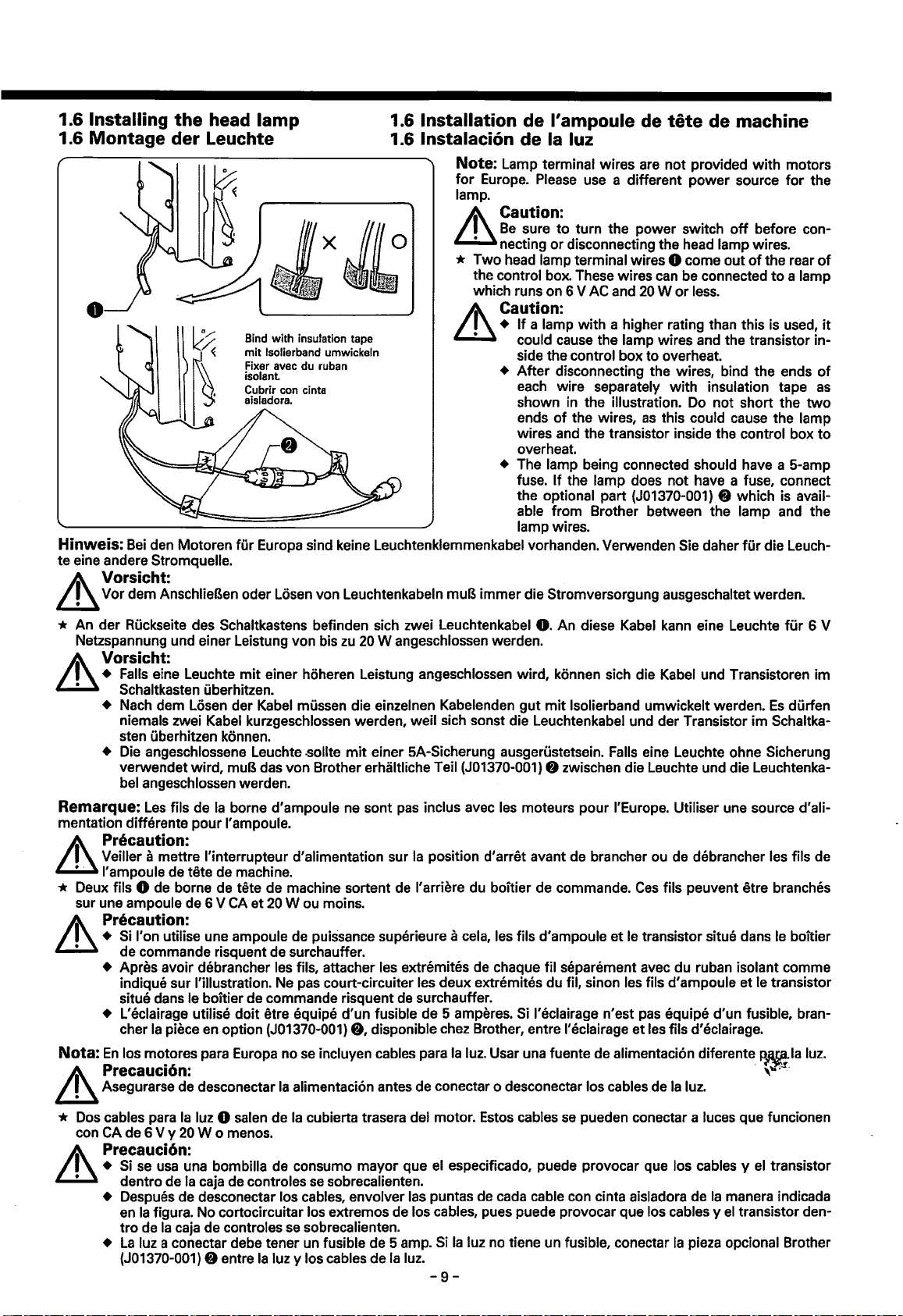
1.6 Installing the head lamp
1.6 Montage der Leuchte
0
Bind with insulation tape
mit
lsolierband umwickeln
Hinweis:
te eine andere Stromquelle.
Bei
den Motoren fur Europa sind keine Leuchtenklemmenkabel vorhanden. Verwenden Sie daher
A\ Vorsicht:
~
Vor dem AnschlieBen oder Losen von Leuchtenkabeln muB immer die Stromversorgung ausgeschaltet werden.
1.6 Installation de l'ampoule de
1.6
lnstalacion de
Ia
luz
Note: Lamp terminal wires are not provided
for
Europe.
lamp.
Please
use a different power source
A\ Caution:
~Be
• necting
sure
to
turn the power switch
or
disconnecting the head lamp wires.
* Two head lamp terminal wires 0 come out
the control box. These wires can be connected
which runs on 6 V AC and
It\ Caution:
~
+
If
a lamp with a higher rating than this is used,
could cause the lamp wires and the transistor in-
side the control box
+ After disconnecting the wires, bind the ends
each wire separately with insulation tape
shown
ends
wires and the transistor inside the control box
overheat.
+ The lamp being connected should have a 5-amp
fuse.
the optional part
able from Brother between the lamp and the
lamp wires.
in
the illustration. Do not short the
of
the wires,
If
the lamp does not have a fuse, connect
20 W or
to
as
(J01370-001). 8 which is avail-
tete
de machine
with
motors
for
the
off
before con-
of
the rear
less.
overheat.
this could cause the lamp
fur
die Leuch-
to
a lamp
of
it
of
as
two
to
* An der Ruckseite des Schaltkastens befinden sich zwei Leuchtenkabel
Netzspannung und einer Leistung von bis
zu
20
W angeschlossen werden.
0.
An diese Kabel kann eine Leuchte
Vorsicht:
+ Falls eine Leuchte
Schaltkasten uberhitzen.
• Nach dem Losen der Kabel mussen die einzelnen Kabelenden
niemals zwei Kabel kurzgeschlossen werden, weil sich sonst die Leuchtenkabel und der Transistor im Schaltkasten uberhitzen konnen.
+ Die angeschlossene Leuchte .sollte
verwendet wird,
bel angeschlossen werden.
Remarque:
mentation differente pour I' ampoule.
Les
fils de
mit
einer hoheren Leistung angeschlossen wird, konnen sich die Kabel und Transistoren im
gut
mit
lsolierband umwickelt werden.
mit
muB das von Brother erhaltliche Teil (J01370-001) 8 zwischen die Leuchte und die Leuchtenka-
Ia
borne d'ampoule ne sont
einer 5A-Sicherung ausgerustetsein. Falls eine Leuchte ohne Sicherung
pas
inclus avec les moteurs pour I'Europe. Utiliser une source d'ali-
Precaution:
&
Veiller a mettre l'interrupteur d'alimentation sur
I' ampoule de tete de machine.
* Deux fils 0 de borne de tete de machine sortent
sur une ampoule de 6 V
CA
et
20
W ou moins.
Ia
position d'arret avant de brancher ou de debrancher les fils de
de
l'arriere du boitier de commande.
Ces
fils peuvent etre branches
Precaution:
~
de commande risquent de surchauffer.
I' on utilise une ampoule de puissance superieure a cela, les fils d'ampoule
et
le
transistor situe dans
+
Si
+ Apres avoir debrancher les fils, attacher les extremites de chaque fil separement avec du ruban isolant comme
indique sur !'illustration. Ne pas court-circuiter les deux extremites du fil, sinon les fils d'ampoule et le transistor
situe dans le boitier de commande risquent
+ L'eclairage utilise doit etre equipe d'un fusible de 5 amperes.
char
Ia
piece
en
Nota:
option (J01370-001)
En
los motores para Europa no
se
8,
incluyen cables para
de
surchauffer.
Si
disponible chez Brother, entre l'eclairage et les fils d'eclairage.
Ia
luz. Usar una fuente de alimentaci6n diferente
l'eclairage n'est
pas
equipe d'un fusible, bran-
A\ Precauci6n: -
~
Asegurarse de desconectar
Ia
alimentaci6n antes de conectar o desconectar los cables de
Ia
luz.
fur
6 V
Es
durfen
le
boitier
~Ia
luz.
''"·~-
* Dos cables para
con
CA de 6 V y
Ia
luz 0 salen de
20
W o me
nos.
Ia
cubierta trasera del motor. Estos cables
se
Precauci6n:
+
Si
se
usa
una bombilla de consumo mayor que el especificado, puede provocar que los cables y el transistor
Ia
dentro de
caja de controles
se
sobrecalienten.
+ Despues de desconectar los cables, envolver las puntas de cada cable con cinta aisladora de
Ia
figura. No cortocircuitar los extremos de los cables, pues puede provocar que los cables y
en
tro
de
Ia
+
La
(J01370-001) 8 entre
caja de controles
luz a conectar debe tener un fusible de 5 amp.
se
sobrecalienten.
Ia
luz y los cables de
Ia
luz.
Si
Ia
luz no tiene un fusible, conectar
-9-
pueden conectar a luces que funcionen
Ia
manera indicada
el
transistor den-
Ia
pieza opcional Brother
Page 15
2. INSTALLING OPTIONS 2. MONTAGEOPTIONEN
2.
INSTALLATION
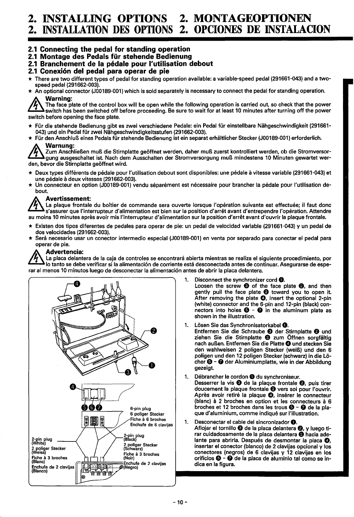
2.1
Connecting
2.1
Montage des Pedals fur stehende Bedienung
2.1
Branchement de Ia pedale pour l'utilisation debout
2.1
Conexi6n del pedal para operar de pie
* There are
speed pedal (291662-003).
two
* An optional connector (J00189-001) which is sold separately
Warning:
The face plate
switch
switch before opening the face plate.
* Fur die stehende Bedienung
043)
und ein Pedal
* Fur den AnschluB eines Pedals
Warnung:
Zum AnschlieBen muB die Stirnplatte geoffnet werden, daher muB zuerst kontrolliert werden, ob die Stromversorgung ausgeschaltet ist. Nach dem Ausschalten der Stromversorgung muB mindestens
den, bevor die Stirn platte geoffnet wird.
* Deux types differents de pedale pour I' utilisation debout sont disponibles: une pedale a vitesse variable (291661-043)
une pedale a deux vitesses (291662-003).
* Un connecteur
bout.
Avertissement:
La
plaque frontale du boitier
s'assurer que l'interrupteur d'alimentation est bien sur
au
moins
10
minutes apres avoir mis l'interrupteur d'alimentation sur
* Existen dos tipos diferentes de pedales para operar de pie: un pedal de velocidad variable (291661-043) y un pedal de
dos velocidades (291662-003).
* Sera necesario usar un conector intermedio especial (J00189-001)
operar de pie.
fA..
Advertencia:
~La
rar
placa delantera de
lo tanto
al
menos
10
the
pedal for standing operation
different types
of
has
se
minutos luego de desconectar
the control box will
been switched
tor
zwei Nahgeschwindigkeitsstufen (291662-003).
en
option (J00189-001) vendu separement est necessaire pour brancher
debe verificar
DES
of
pedal
for
off
before proceeding.
gibt
es
zwei verschiedene Pedale: ein Pedal
fur
stehende Bedienung ist ein separat erhaltlicher Stecker (J00189-001) erforderlich.
de
commande sera ouverte lorsque !'operation suivante est effectuee; il taut done
Ia
caja de controles
si
Ia
alimentaci6n de corriente esta desconectada antes de continuar. Asegurarse de espe-
6-pin plug
6 poliger Stecker
Fiche
Enchufe de 6 clavijas
OPTIONS
standing operation available: a variable-speed pedal (291661-043) and a
be
open while the following operation is carried out, so check that the power
se
encontrara abierta mientras
Ia
alimentaci6n antes de abrir
a 6 broches
Be
2.
OPCIONES
is
necessary
sure
to
wait
Ia
position d'arret avant d'entrependre I' operation. Attendre
1.
Disconnect the synchronizer cord
Loosen the screw 8
gently
After removing the plate G, insert the optional 2-pin
(white) connector and the 6-pin and 12-pin (black) connectors into holes
shown in the illustration.
1.
Losen Sie das Synchronisatorkabel
Entfernen Sie die Schraube 8 der Stirnplatte 8 und
ziehen
nach
den wahlweisen 2 poligen Stecker (weiB) und den 6
poligen und den
cher 8 - 0 der Aluminium platte, wie in der Abbildung
gezeigt.
1.
Debrancher
Desserrer
doucement
Apres avoir retire
(blanc) a 2 broches
broches
que d'aluminium, comme indique sur
1.
Desconectar
Aflojar
rar cuidadosamente de
lante para abrirla. Despues de desmontar
insertar
conectores (negros) de 6 clavijas y
orificios 0 - G de
dica
to
connect the pedal
for
at least
fur
einstellbare Nahgeschwindigkeit (291661-
Ia
position d'arret avant d'ouvrir
en
venta por separado para conectar
se
Ia
placa delantera.
pull the face plate e toward you
Sie
die Stirnplatte 8 zum Qffnen sorgfaltig
au
Ben.
Entfernen Sie die Platte G und stecken Sie
le
Ia
vis 8 de
Ia
et
12
el
el
tornillo 8 de
el
conector (blanco) de 2 clavijas opcional y los
en
Ia
figura.
DE
INSTALACION
for
standing operation.
10
minutes after turning
10
Minuten gewartet war-
Ia
pedale pour !'utilisation de-
realiza
el
siguiente procedimiento, por
off
Ia
plaque frontale.
el
0.
of
the face plate
8,
e - G in the aluminum plate
0.
12
poligen Stecker (schwarz) in die Lo-
cordon 0 du synchroniseur.
Ia
plaque frontale 8 vers soi pour l'ouvrir.
broches dans les trous 8 - G de
cable del sincronizador
plaque frontale
Ia
plaque
en
Ia
placa de aluminio tal como
G,
option et les connecteurs a 6
Ia
placa delantera
Ia
placa delantera 8 hacia ade-
inserer le connecteur
8,
!'illustration.
0.
8,
Ia
12
clavijas
to
two-
the power
et
pedal para
and then
open it.
as
puis tirer
Ia
pla-
y luego ti-
placa
G,
en
los
se
in-
-10-
Page 16
A2-pin
V(White}
3.
3.
3.
3.
Conector
6 clavijas
de
connector
2
P<?lig_er
(WeiSS)
Connecteur
2 broches
Conector de
2
For variable-speed pedal
Fur Pedal
Nahgeschwindigkeit
Pour
Para pedal de velocidad variable
Stecker
(Blanc}
clavijas (Blanco)
mit
einstellbarer
Ia
pedale a vitesse variable
2-pin connector
(Black)
2 poliger Stecker
(Schwarz)
Connecteur
2 broches (Noir)
Conector de
clavijas (Negro)
2
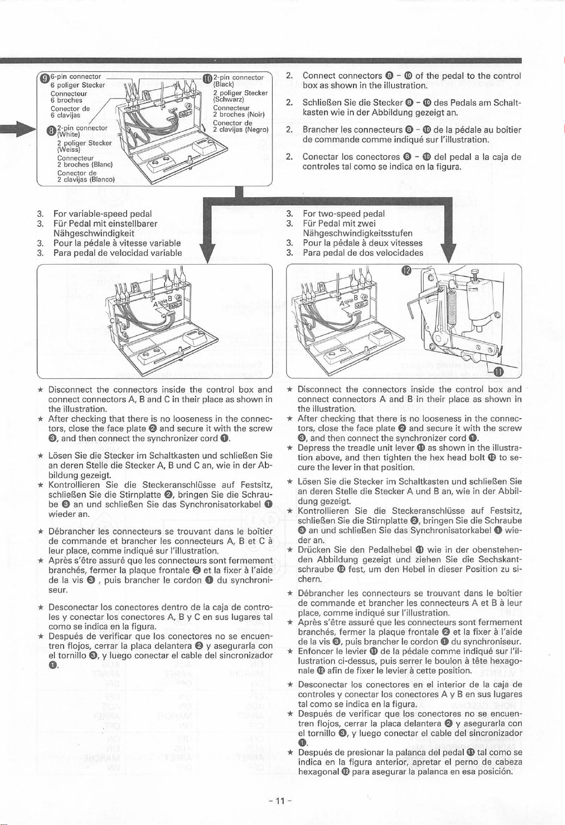
2.
Connect connectors 0 -~ of
box
as
shown in the illustration.
2.
SchlieBen Sie die Stecker 0 -~ des Pedals am Schalt-
der
kasten wie in
2.
8rancher les connecteurs
de commande com
2.
Conectar los conectores 0 -~ del pedal a
controles tal como
3.
For two-speed pedal
3.
Fur Pedal
Nahgeschwindigkeitsstufen
3.
Pour
Ia
pedale a deux vitesses
3.
Para pedal de dos velocidades
Abbildung gezeigt
me
se
mit
zwei
indique sur !'illustration.
indica
0-
en
the pedal
~de
Ia
figura.
to
an.
Ia pedale au boitier
the
control
Ia
caja de
* Disconnect the connectors inside the control box and
connect connectors
the
illustration.
*
After
checking that there is no looseness in the connec-
tors, close the face plate e and secure
E), and then connect
* Losen Sie die Stecker
an
deren Stelle die Stecker A, 8 und
bildung gezeigt.
* Kontrollieren Sie die Steckeranschlusse
schlieBen Sie die Stirnplatte
be
E)
an und schlieBen Sie das Synchronisatorkabel 0
wieder
an.
* Debrancher les connecteurs
de commande
leur place, com me indique sur !'illustration.
* Apres s'etre assure que l
branches, fermer
Ia
vis E) , puis brancher le cordon 0 du synchroni-
de
seur.
* Desconectar los conectores dentro
es
y conectar lo s conectores A, 8 y C en sus lugares tal
l
se
como
indica en
* Despues de verificar que los conectores
tren flojos, cerrar
el tornillo
0.
E), y luego conectar el cable del sincronizador
A, 8 and C in
the
synchronizer cord
im
Schaltkasten und schlieBen Sie
et
brancher les connecteurs A, 8 et C a
es
Ia
plaque frontale @
Ia
figura.
Ia
placa delantera @ y asegurarla con
their
Can,
@,
bringen Sie
se
trouvant
connecteurs
de
place
as
shown in
it
with
the
0.
wie in der Ab-
auf
Festsitz,
die
Schrau-
dans le boitier
sont
fermement
et
Ia fixer a !'aide
Ia caja de contro-
no
se
encuen-
screw
* Disconnect the connectors inside the control
connect connectors A and 8 in
the illustration.
*
After
checking
tors, close the face plate e and secure
E), and then connect the synchronizer cord
* Depress
tion
above, and then tighten the hex head
cure the lever in
* Losen Sie die Stecker
an deren Stelle die Stecker A und 8 an,
dung gezeigt.
that
there
the
treadle unit lever
that
position.
im
* Kontrollieren Sie die Steckeranschlusse
schlieBen Sie die Stirn platte@, bringen Sie die Schraube
E)
an
und
der
schlieBen Sie das Synchronisatorkabel 0
an.
* Drucken Sie den Pedalhebel
den Abbildung gezeigt und ziehen
schraube
chern.
* Debrancher l
de commande
place,
* Apres s'etre assure
branches, fermer Ia plaque frontale @
de
* Enfoncer le levier
lustration ci-dessus, puis serrer le bouton
nale
m fest,
comme
Ia
vis E), puis brancher le cordon 0 du synchroniseur.
m afin de
um
den Hebel in dieser Position
es
connecteurs
et
brancher les connecteurs A et 8 a leur
indique sur !'illustration.
que
les connecteurs
CD
de
Ia
fixer
le levier a cette position.
* Desconectar los conectores en
controles y conectar los conectores A y 8 en sus lugares
tal como
* Despues de verificar
tren flojos, cerrar
el
se
indica en
tornillo E), y luego conectar el cable del sincronizador
Ia
figura.
que
Ia
placa delantera @ y asegurarla con
their
place
is
no looseness in the connec-
it
CD
as
shown in the illustra-
Schaltkasten und schlieBen Sie
CD
se
pedale comme indique sur l'il-
los conectores no
wie
wie in
der
Sie
trouvant dans le boitier
sont
et
el
interior de
box
as
shown in
with the screw
0.
bolt
m to se-
in
der
auf
Festsitz,
obenstehen-
die
Sechskant-
fermement
Ia
fixer
a !'aide
a tete hexago-
Ia
caja de
se
encuen-
0.
* Despues de presionar Ia palanca del pedal
indica en
hexagonal
Ia
figura anterior, apretar el perno de cabeza
m para asegurar
Ia palan
ca
en
CD
tal como se
esa posicion.
and
Abbil-
wie-
zu
si-
-
11
-
Page 17
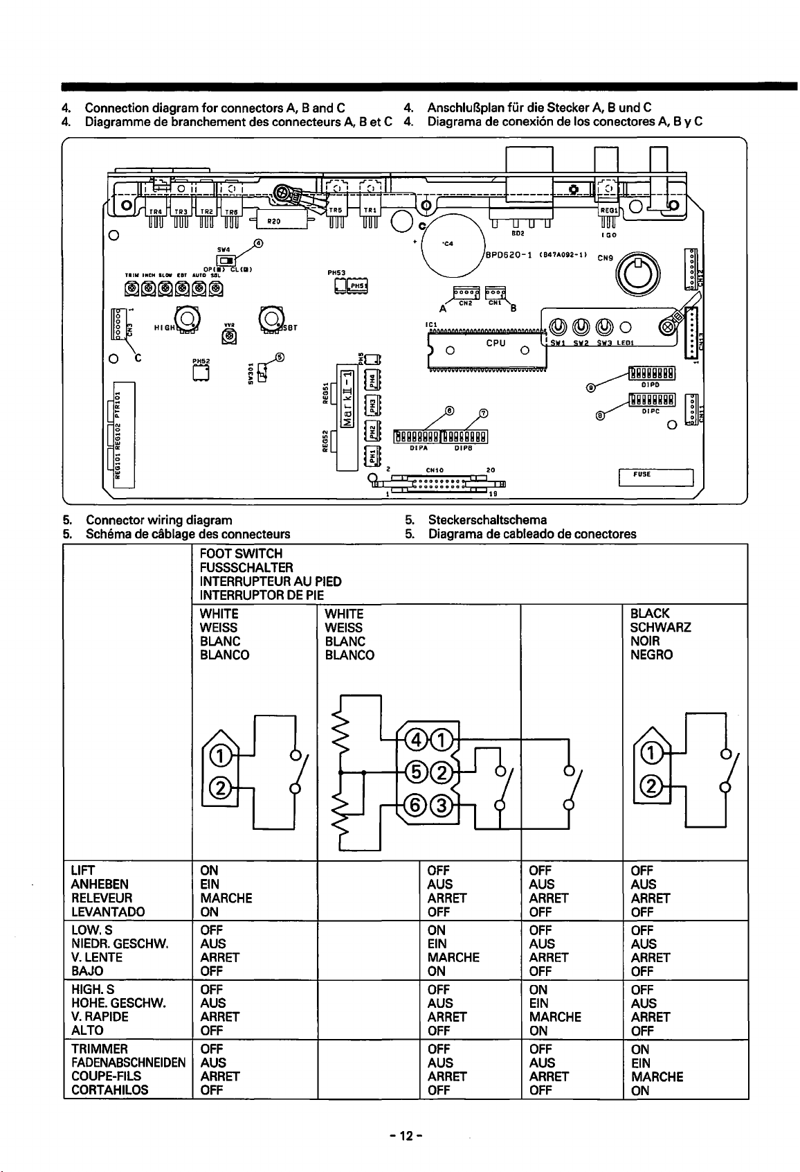
4.
Connection diagram for connectors
4.
Diagramme
de
branchement
0
~
TRill
INCH
SLOW
OPt•>
UT
AUTO
S8L
JI
ruz
0 c
N
0
..
g
D<
D
§
D<
CLIIII
des
connecteurs
A, B and
N
ltl
g
D<
C
A,
B et C
PH
53
bj~
4.
AnschluBplan fur
4.
Diagrama
0
de
conexi6n
CPU O
die
Stecker
de
los
A, B und
C
conectores
FUSE
A,
B y C
5.
Connector wiring diagram
5.
Schema
de
cablage
LIFT
ANHEBEN
RELEVEUR
LEVANT
ADO
LOW.S
NIEDR.
V.
GESCHW.
LENTE
BAJO
HIGH.S
HOHE.
GESCHW.
V.
RAPIDE
ALTO
TRIMMER
FADENABSCHNEIDEN
COUPE-FILS
CORTAHILOS
des
connecteurs
FOOT
SWITCH
FUSSSCHALTER
INTERRUPTEUR
INTERRUPTOR
DE
WHITE
WEISS
BLANC
BLANCO
ON
EIN
MARCHE
ON
OFF
AUS
ARRET
OFF
OFF
AUS
ARRET
OFF
OFF
AUS
ARRET
OFF
AU
PIED
PIE
WHITE
WEISS
BLANC
BLANCO
5.
Steckerschaltschema
5.
Diagrama
de
OFF
AUS
ARRET
OFF OFF
ON
EIN
MARCHE
ON
OFF
AUS
ARRET
OFF
OFF
AUS
ARRET
OFF OFF
cableado
OFF
AUS
ARRET
OFF
AUS
ARRET
OFF
ON
EIN
MARCHE
ON
OFF
AUS
ARRET
de
conectores
BLACK
SCHWARZ
NOIR
NEGRO
OFF
AUS
ARRET
OFF
OFF
AUS
ARRET
OFF
OFF
AUS
ARRET
OFF
ON
EIN
MARCHE
ON
-12-
Page 18

2.2 Connecting
the
operation panel
2.2 AnschlieBen der Bedienungstafel
2.2 Branchement du panneau de commande
2.2 Conexi6n
* The
E-20,
Warning:
The face plate
switch
switch before opening the face
*
FOr
die Bedienung dieses Motors konnen die Bedienungstafeln
fA..
Warnung:
~
Zum AnschlieBen muB die Stirn platte geoffnet werden, daher muB zuerst kontrolliert werden, ob die Stromversorgung
den, bevor die
*
Les
panneaux de commande
Avertissement:
La
plaque frontale du boitier de commande sera ouverte lorsque !'operation suivante est effectuee; il
s'assurer que l'interrupteur
au
moins 10 minutes apres avoir mis l'interrupteur d'alimentation sur
* Los paneles de control
Advertencia:
La
placa delantera de
lo tanto
al
menos 10 minutos luego de desconectar
rar
del panel de control
E-40
and E-100 operation panels can be connected and used
of
has
ausgeschaltet ist. Nach dem Ausschalten der Stromversorgung muB mindestens 10 Minuten gewartet wer-
Stirn platte geoffnet wird.
se
the control box will be open while the following operation is carried out, so check that the power
been switched
E-20,
debe verificar si
off
before proceeding.
plate.
E-20,
E-40
et
E-100 peuvent etre branches et utilises avec ce moteur.
d'alimentation est bien sur
E-40
y E-100
Ia
caja de controles
Ia
alimentaci6n de corriente esta desconectada antes de continuar. Asegurarse de espe-
se
pueden conectar y usar con este motor.
Ia
Be
sure
to
E-20,
Ia
position d'arret avant d'entrependre I' operation. Attendre
se
encontrara abierta mientras se realiza
alimentaci6n antes de abrir
* Disconnect the synchronizer cord
* Loosen the screw e
pull
*
After
align the
the
curely insert operation panel connector e until the pawl
locks.
* Clamp the cord 0
lustration,
careful
* Close the face plate E) and secure
* Connect the synchronizer cord
* Losen Sie das des Synchronisatorkabel
with
this motor.
wait
for
at
least 10 minutes after turning
E-40
oder E-100 verwendet werden.
Ia
position d'arret avant
Ia
placa delantera.
the face plate e toward you
opening the pawl
'Y
'Y
mark on operation panel connector e
mark on the circuit board connector
and then install the control box while being
not
to
with
damage the cord
d'ouvrir
el
siguiente procedimiento,
of
the control box, and then gently
of
the circuit board connector
the rubber
G.
0.
Ia
plaque frontale.
0.
to
open it.
CD
as
it
with the screw
0.
* Entfernen Sie die Schraube e am Schaltkasten und zie-
hen
Sie die Stirnplatte 8 zum Offnen sorgfaltig nach au-
Ben.
* Offnen Sie die Sicherung des Schaltplatinensteckers 8
und losen die den AnschluB. Richten Sie die Markierung
'Y
des Bedienungstafelsteckers 8
den Markierung
und stecken
* Bringen Sie den Gummi
Kabel G
Sie den Bedienungstafelstecker 8 hinein, so daB die Steckersicherung richtig eingreift.
CD
wie
zu
beschadigen.
in der Abbildung gezeigt am Kabel G
an
* *SchlieBen Sie die Stirnplatte E) und bringen Sie die Schraube e wieder
* SchlieBen Sie das Synchronisatorkabel 0 wieder
* Debrancher
* Desserrer
* Apres avoir ouvert le cliquet d'arret du connecteur 8 de
teur
8 du panneau de commande avec le repere
mement
* Attacher le cordon G avec le caoutchouc
mande
* Refermer
le
cordon 0 du synchroniseur.
Ia
vise
du boitier de commande, puis tirer doucement
le connecteur 8 du panneau de commande jusqu'a
en
prenant so in de
Ia
plaque frontale E)
ne
pas endommager le cordon
et
Ia
fixer a I' aide de
CD
an.
Ia
Ia
'Y
de
Ia
maniere indiquee sur !'illustration, puis installer le boitier de com-
carte a circuits, aligner le repere
marque sur le connecteur 8 de
plaque frontale E) vers soi
ce
que le cliquet d'arret
G.
Ia
vis
e.
'Y
des Schaltplatinensteckers 8 aus
und montieren Sie den Schaltkasten ohne das
an.
Ia
carte a circuits, puis inserer fer-
se
verrouille.
mit
der entsprechen-
pour
l'ouvrir.
'Y
marque sur le connec-
* Brancher le cordon 0 du synchroniseur.
* Debrancher le cordon 0 du synchroniseur.
* Desserrer
* Apres avoir ouvert le cliquet d'arret du connecteur 8 de
teur
mement
* Attacher le cordon G avec le caoutchouc
de
* Refermer
* Brancher le cordon 0
Ia
vise
du boitier de commande, puis tirer doucement
8 du panneau de commande avec le repere
le connecteur 8 du panneau de commande jusqu'a ce que le cliquet d'arret
CD
en
prenant soin de ne pas endommager le cordon
Ia
plaque frontale
E)
du
et
synchroniseur.
Ia
fixer a I' aide de
'Y
de
Ia
maniere indiquee sur !'illustration, puis installer le boitier de comman-
Ia
marque sur le connecteur 8 de
G.
Ia
vis
e.
Ia
carte a circuits, aligner le repere
plaque frontale E) vers soi pour l'ouvrir.
'Y
Ia
carte a circuits, puis inserer fer-
se
verrouille.
marque sur le connec-
off
the power
taut
done
por
8,
with
e,
and se-
shown in the il-
e.
-13-
Page 19

2.3 Connecting the material edge sensor
AnschlieBen des Stoffkantensensors
2.3
du
2.3 Branchement
Conexi6n del sensor de borde de material
2.3
* The sensor-1,
* The
sensor-11
Warning:
The face plate
check that the
turning
~
/A.
off
Caution:
If
connecting the
sensor-11
is used in conjunction
the
power
detecteur de bords du tissu
and sensor-Ill material edge sensors can all be connected.
of
the control box
power
switch has been switched
switch before opening the face plate.
sensor-11
with
the E-20, E-40 and E-100 operation panels, and cannot be used
will
be open
sensor, be sure
to
turn the
by
while
the sensor-1 and sensor-Ill sensors are being connected, so
off
before proceeding.
power
switch
Be
sure
off
before carrying
to
wait
for
at
least 10 minutes after
out
the
operation below.
itself.
* Die Stoffkantensensoren
* Der Stoffkantensensor
I, II
und Ill konnen angeschlossen werden.
II
kann
nur
mit
den Bedienungstafeln E-20, E-40 oder E-100
Warnung:
Zum
AnschlieBen des Sensors I und Ill muB die Stirnplatte geoffnet werden, daher muB zuerst kontrolliert werden,
ob
die Stromversorgung ausgeschaltet
ten gewartet werden, bevor
JA.
Vorsicht:
~
Zum
AnschlieBen des Sensors
* Les detecteurs
*
Le
detecteur-11 est utilise en conjonction avec les panneaux de commande E-20, E-40
lise independamment.
de
bords
die
Stirn platte
II
du
tissu detecteur-1, detecteur-11
ist
Nach
dem
Ausschalten
geoffnet
muB die Stromversorgung ausgeschaltet werden.
wird.
et
detecteur-111
der
Avertissement:
La
plaque frontale du boitier de commande sera ouverte pendant que les detecteurs detecteur-1
sont branches; il faut done s'assurer que l'interrupteur d'alimentation est bien
pendre
d'ouvrir
I' operation. Attendre au moins
Ia
plaque frontale.
10
minutes apres avoir mis l'interrupteur d'alimentation
Precaution:
Si
l'on
branche le detecteur detecteur-11, veiller a mettre l'interrupteur d'alimentation
d'
entreprendre I' operation ci-dessous.
*
Se
pueden conectar los sensores de borde de material: Sensor-1,
*
El
Sensor-11
se
usa
junto
con los paneles de control E-20, E-40 y E-100, y
Sensor-11
nose
A\ Advertencia:
~La
se de esperar
placa delantera de
sor-Ill
por lo tanto
al
menos 10 minutos luego de desconectar
Ia
caja de controles se encontrara abierta mientras
se
debe verificar si
Ia
alimentaci6n de corriente esta desconectada antes de continuar. Asegurar-
Ia
alimentaci6n antes de abrir
A\ Precauci6n:
~AI
(1)
(1)
conectar el sensor
• dicado a continuaci6n.
Connecting the sensor-
Branchement
du
II
detecteur detecteur-11
Sensor-11,
sensor
asegurarse de apagar el interrupter principal antes de realizar el procedimiento'
(1)
AnschlieBen des Sensors
(1)
Conexi on del sensor Sensor-
* Push the material edge sensor connector E) into the
connector
as
far
as
it
Note:
* The illustration
machine head is
* Drucken Sie den Stecker 8 des Stoffkantensensors so
weit
wie
de
moglich in den Stecker
8edienungstafel
Hinweis:
*
Auf
der
montiertem
* Pousser bien a
bords
du
panneau
de
Remarque:
* L'illustration ci-contre a gauche represente le cas ou
tete de
* Empujar el conector del' sensor de borde
hacia adentro del conector
de control
Nota:
*
La
de
-14-
Ia
figura a
maquina 8737 se encuentra instalada.
verwendet
Stromversorgung muB mindestens 10
peuvent tous etre branches.
sur
et
E-100,
Ia
position
werden.
sur
sur
Ia
et
ne
d'arret
Ia
position
position
peut
pas etre
et
avant d'entre-
d'arret
d'arret
y Sensor-Ill.
pueden usar solos.
se
conectan los sensores Sensor-1 y Sen-
Ia
placa delantera.
II
II
f)
on
the
will
go.
at
left
installed.
right side
shows the case
of
the
operation panel 0
when
f)
auf
der
rechten Seite
0.
linksstehenden Abbildung
Maschinenoberteil 8737
fond
tissu dans le connecteur
commande
machine 8737 est installee.
0 tanto
Ia
izquierda indica el caso en
le connecteur 8
0.
f)
como
del lado derecho del panel
sea posible.
wird
der
gezeigt
du
detecteur de
f)
situe a droite
de
que
Minu-
uti-
detecteur-111
avant
avant
in-
the
8737
Fall
mit
du
Ia
material E)
una cabeza
Page 20

(2)
Connecting the
(2)
AnschlieBen des Sensors I und des Sensors Ill
(2)
Branchement des detecteurs detecteur-1
(2)
Conexi6n de los sensores Sensor-I y Sensor-Ill
sensor-1
and sensor-Ill sensors
et
detecteur-111
* Disconnect the synchronizer cord
* Loosen the screw e
pull
the face plate e toward you
* After opening the pawl
align the
the
curely insert operation panel connector e until the pawl
locks.
'Y
'Y
mark on operation panel connector e with
mark on the circuit board connector G, and se-
* Clamp the cord G
lustration,
careful
and then install the control box while being
not
to
damage the cord
of
the control box, and then gently
of
the circuit board connector
with
the rubber
* Close the face plate E) and secure
* Connect the synchronizer cord
0.
to
open it.
C)
as
G.
it
with the screw
0.
shown in the il-
G,
e.
* Losen Sie das Synchronisatorkabel
* Entfernen Sie die Schraube e am Schaltkasten und zie-
hen
Sie die Stirnplatte E) zum Offnen sorgfaltig nach au-
Ben.
* Ottnen Sie die Sicherung des Schaltplatinensteckers G
und losen die den AnschluB. Richten Sie die Markierung
'Y
des Bedienungstafelsteckers 0
den Markierung
so
daB die Steckersicherung richtig eingreift.
* Bringen Sie den Gummi
Kabel G
zu
beschadigen.
C)
wie
in der Abbildung gezeigt am Kabel G
und stecken
* SchlieBen Sie die Stirnplatte E) und bringen Sie die Schraube e wieder
* SchlieBen Sie das Synchronisatorkabel 0 wieder
an.
* Debrancher le cordon 0 du synchroniseur.
* Desserrer
* Apres avoir ouvert le cliquet d'arret du connecteur G de
teur
mement
* Attacher le cordon G avec le caoutchouc
prenant soin de ne pas endommager le cordon
* Refermer
* Brancher le cordon 0 du synchroniseur.
* Desconectar el cable del sincronizador
* Aflojar
* Despues de liberar
marca
de trabada.
* Enganchar
do
* Cerrar
* Conectar el cable del sincronizador
Ia
vise
du boitier de commande, puis tirer doucement
0 du panneau de commande avec le repere
le connecteur 0 du panneau de commande jusqu'a ce que le cliquet d'arret
C)
'Y
comme indique sur !'illustration, puis installer le boitier de commande
Ia
marque sur le connecteur G de
Ia
plaque frontale E) vers soi pour l'ouvrir.
carte a circuits, aligner le repere
G.
Ia
plaque frontale E) et
Ia
fixer a I' aide de
Ia
vis
e.
0.
el
tornillo e de
'Y
en
el
conector del circuito
el
cable G con
de no danar
Ia
placa delantera E) y asegurarla con el tornillo
Ia
caja de controles, y luego tirar ligeramente
Ia
una del conector del circuito
G,
Ia
goma
C)
el
cable
G.
G,
alinear
e insertar seguramente
tal como
se
indica en
e.
Ia
Ia
marca
el
conector del panel de control e hasta que
Ia
figura, luego instalar
0.
0.
mit
der entsprechen-
'Y
Sie den Bedienungstafelstecker 0 hinein,
an
und montieren Sie den Schaltkasten ohne das
an.
placa delantera E) hacia adelante.
'Y
en
des Schaltplatinensteckers G aus
'Y
Ia
carte a circuits, puis inserer fer-
se
verrouille.
el
conector de panel de control 0 con
Ia
caja de controles teniendo cuida-
marque sur le connec-
Ia
una que-
en
Ia
-
15-
Page 21

2.4 Connecting
AnschlieBen des Spulenfadensensors
2.4
the
bobbin thread sensor
2.4 Branchement du detecteur de fil de canette
2.4 Conexi6n
Warning:
The face plate
switch has been switched
switch before opening the face plate.
Warnung:
Zum AnschlieBen muB die Stirn platte geoffnet werden, daher muB zuerst kontrolliert werden, ob die Stromversor-
gung ausgeschaltet
den, bevor die Stirn platte geoffnet wird.
Avertissement:
La
plaque frontale du boitier de commande sera ouverte pendant qu'on effectue !'operation suivante; il faut done
s'assurer que l'interrupteur
au
moins 10 minutes apres avoir mis l'interrupteur d'alimentation sur
Advertencia:
La
placa delantera de
lo tanto
rar
al
menos
del sensor de hilo de bobina
of
the control box will
se
debe verificar si
10
minutes luego de desconectar
off
before proceeding.
ist
Nach dem Ausschalten der Stromversorgung muB mindestens 10 Minuten gewartet
d'alimentation est bien sur
Ia
caja de controles
Ia
alimentaci6n de corriente esta desconectada antes de continuar. Asegurarse de espe-
be
open while the following operation is carried out, so check that the power
Ia
alimentaci6n antes de abrir
Be
sure to
se
encontrara abierta mientras
wait
for
Ia
position d'arret avant d'entrependre I' operation. Attendre
Ia
position d'arret avant
* Disconnect the synchronizer cord
* Loosen the screw e
pull the face plate 8 toward you
at least 10 minutes after turning
se
realiza
Ia
placa delantera.
d'ouvrir
el
siguiente procedimiento,
Ia
plaque frontale.
0.
of
the control box, and then gently
to
open
* Connect the bobbin thread sensor panel connectors 0
and G securely
respectively.
* Clamp the cords 0 and
in the
illustration, and then install the control box while
being careful
* Close the face plate 8 and secure
* Connect the synchronizer cord
to
circuit board connectors G and 0
~
with
the rubber 0
not
to
damage the cords 0 and
it
with the screw
0.
off
it
the power
war-
por
as
shown
~-
e.
* Losen Sie das Synchronisatorkabel
0.
* Entfernen Sie die Schraube e am Schaltkasten und zie-
hen
Sie die Stirnplatte e zum Offnen sorgfaltig nach au-
Ben.
* SchlieBen Sie die Stecker des Spulenfadensensors 0
* SchlieBen Sie das Synchronisatorkabel 0 wieder
* Debrancher le cordon 0 du synchroniseur.
* Desserrer
* Brancher fermement les connecteurs 0
connecteurs G
* Attacher les cordons 0
mande
* Refermer
* Brancher le cordon 0 du synchroniseur.
* Desconectar el cable del sincronizador
* Aflojar
Ia
vise
du boitier de commande, puis tirer doucement
et
et
e de
Ia
carte a circuits.
en
prenant soin de ne pas endommager les cordons 0 et
Ia
plaque frontale 8
et ~ avec le caoutchouc 0 comme indique sur !'illustration, puis installer le boitier de com-
et
Ia
fixer a I' aide de
8 de panneau de detecteur de fil de canette respectivement dans les
0.
el
tornillo e de
Ia
caja de controles, y luego tirar ligeramente
an.
Ia
und 8
G
* Bringen Sie den Gummi 0
an
Schaltkasten ohne die Kabel
* SchlieBen Sie die Stirnplatte e und bringen Sie die
Schraube
vis
e.
an
und0an.
den Kabeln 0 und ~ an und montieren Sie den
Ia
den entsprechenden Schaltplatinensteckern
wie
in der Abbildung gezeigt
0 und
~
zu
beschadigen.
e wieder
plaque frontale 8 vers soi pour l'ouvrir.
an.
e.
Ia
placa delantera 8 hacia adelante.
* Conectar los conectores del panel de sensor de hilo de bobina 0 y 8 con seguridad a los conectores del circuito G y 0
respectivamente.
* Enganchar
dado de no daiiar los cables
* Cerrar
* Conectar el cable del sincronizador
el
cable 0 y ~ con
Ia
placa delantera 8 y asegurarla con
Ia
goma 0 talcomo
0 y
~-
0.
el
tornillo
se
indica en
e.
Ia
figura, luego instalar
Ia
caja de controles teniendo cui-
-16-
Page 22

2.5 Connecting
2.5
AnschlieBen des Stuckgutzahlers
the
production counter
2.5 Branchement du compteur de pieces produites
2.5
Conexi6n del contador de producci6n
* The production counter is used in conjunction
itself.
Warning: ·
The face plate
has
switch
switch before opening the face plate.
of
the control box will
been switched
off
before proceeding.
with
the
E-20,
E-40
be
open while the following operation is carried out, so check that the power
Be
sure
to
wait
and
E-100
operation panels, and cannot be used by
for
at least 10 minutes after turning
off
the power
* Der Stuckgutzahler kann nur zusammen
Warnung:
Zum AnschlieBen muB die Stirnplatte geoffnet werden, daher muB zuerst kontrolliert werden, ob die Stromversorgung ausgeschaltet ist.. Nach dem Ausschalten der Stromversorgung
den, bevor die
*
Le
compteur de pieces produites est utilise
peut pas
Avertissement:
&
&
La
s'assurer que l'interrupteur
au
moins
*
El
contador de producci6n
Advertencia:
La
lo tanto
al
menos 10 minutos luego de desconectar
rar
Stirn platte geoffnet wird.
etre utilise independamment.
plaque frontale du boitier de commande sera ouverte pendant qu'on effectue !'operation suivante; il faut done
10
minutes apres avoir mis l'interrupteur d'alimentation sur
placa delantera de
se
debe verificar si
d'alimentation est bien sur
se
usa
junto con los paneles de control
Ia
caja de controles
Ia
alimentaci6n de corriente esta desconectada antes de continuar. Asegurarse de espe-
mit
den Bedienungstafeln
en
conjonction avec les panneaux de commande
Ia
se
encontrara abierta mientras
Ia
alimentaci6n antes de abrir
E-20,
E-40
oder E-100 verwendet werden.
muB mindestens
position d'arret avant d'entrependre I' operation. Attendre
Ia
position d'arret avant d'ouvrir
E-20,
E-40
y E-100, y
se
Ia
placa delantera.
* Disconnect the synchronizer cord
* Loosen the screw e
pull the face plate e toward you
* Connect the production counter connector 8 securely
to
circuit board connector
* Clamp the cord 0
lustration, and then install the control box while being
not
to
careful
damage the cord
* Close the face plate E) and secure
* Connect the synchronizer cord
10
Minuten gewartet wer-
E-20,
E-40
et
Ia
plaque frontale.
nose
puede usar solo.
realiza
el
siguiente procedimiento,
0.
of
the control box, and then gently
to
open it.
e.
with
the rubber &
as
0.
it
with the screw
0.
shown in the il-
E-100, et ne
por
e.
* Losen Sie das Synchronisatorkabel
0.
* Entfernen Sie die Schraube e am Schaltkasten und zie-
hen
Sie die Stirnplatte
Ben.
E)
zum Offnen sorgfaltig nach au-
* SchlieBen Sie den Stecker 8 des Stuckgutzahlers fest
am Schaltplatinenstecker
* Bringen Sie den Gummi &
am Kabel
ne
0
an
das Kabel 0
und montieren Sie den Schaltkasten ohzu
* SchlieBen Sie die Stirnplatte E) und bringen Sie die
* Debrancher le cordon 0 du synchroniseur.
* Desserrer
Ia
vis e du boitier de commande, puis tirer doucement
Schraube
* Schlie
e Wieder
Ben
Sie das Synchronisatorkabel 0 wieder
Ia
plaque frontale E) vers soi
* Brancher fermement le connecteur 8 du compteur de pieces produites dans le connecteur G de
* Attacher le cordon 0 avec le caoutchouc & comme indique sur !'illustration, puis installer le boitier de commande
prenant soin de ne pas endommager
* Refermer
Ia
plaque frontale E)
le
et
cordon G.
Ia
fixer a I' aide de
Ia
vis
e.
* Brancher le cordon 0 du synchroniseur.
* Desconectar
* Aflojar el tornillo 8 de
* Conectar
* Enganchar
do de no
* Cerrar
* Conectar
el
cable del sincronizador
el
conector del contador de producci6n 8 con seguridad a los conectores del circuito
el
cable 0 con
danar
Ia
placa delantera
el
cable del sincronizador
el
cable G.
Ia
caja de controles, y luego tirar ligeramente
Ia
goma & tal como
E)
y asegurarla con el tornillo
0.
0.
se
indica
8.
Ia
placa delantera E) hacia adelante.
en
Ia
figura, luego instalar
G
an.
wie
in der Abbildung gezeigt
beschadigen.
an.
pour
I' ouvrir.
Ia
carte a circuits.
G.
Ia
caja de controles teniendo cuida-
an.
en
-17-
Page 23

3.
STANDARD
ADJUSTMENTS
3.
STANDARDEINSTELLUNGEN
3. REGLAGES STANDARD 3. AJUSTE ESTANDAR
3.1
Adjusting
3.1
Einstellen
3.1
Reglage du
3.1
Ajuste del mecanismo de seguridad de
A\ Caution:
~
B~
sure
A\ Vorsicht:
~
Kontrollieren Sie, ob die Stromversorgung ausgeschaltet ist.
A\ Precaution:
~
Veiller a mettre l'interrupteur d'alimentation sur
A\
Precaucion:
~
Asegurarse de apagar el interrupter principal antes de realizar
105
mm diameter pulley
Riemenscheibe
Durchmesser
Poulie de
Polea
de
the
der
to
turn
mit
105
105
mm de diametre
105
mm de diametro
belt
cover
safety
mechanism
Riemenschutz-Sicherheitsvorrichtung
dispositif
off
the power switch before carrying out this operation.
mm
de securite du couvercle de courroie
Ia
cubierta de Ia correa
Ia
position d'arret avant d'entreprendre cette operation.
3.1.1
3.1.1
3.1.1
3.1.1
* Loosen the screw 0 and then adjust the guide in ac-
cordance with the size
shown in the illustration.
* After adjusting, tighten the screw
Note:
* This safety guide will prevent the belt
even when the machine head is tilted back.
el
siguiente procedimiento.
Adjusting
Einstellen
Reglage du guide de prevention de saute de courroie
Ajuste de Ia guia de prevencion de salida de
rrea
the
belt
der
casting prevention guide
Riemenfuhrung
of
the belt within the range
0.
from
Ia
coming
co-
off
If
the pulley diameter is
105
mm
Bei
einem Riemenscheibendurchmesser von
mehr
als
Si le diametre de
est de
Si
el
diametro de
es
105
* Desserrer
tration.
or more
105
mm
Ia
105
mm o mas
Ia
poulie
mm ou plus
Ia
polea
vis 0 puis regler le guide
If
the pulley diameter is
less than
Bei
einem Riemenscheibendurchmesser von
weniger
Si
le diametre de
est inferieur a
Si el diametro de
es
manor de
* Une fois le reglage accompli, resserrer
Remarque:
*
Ce
guide de securite empeche
* Aflojar
gura.
el
tornillo 0 y ajustar
* Despues de ajustar, apretar
Nota:
*
Esta
guia evitara que
Ia
el
correa
Ia
courroie de sauter marne lorsqu'on incline
Ia
guia de acuerdo con
tornillo
se
salga cuando
105
mm
als
105
105
105
en
fonction de
Ia
vis
0.
mm
Ia
poulie
mm
Ia
polea
mm
0.
el
se
inclina hacia atras
* Losen Sie die Schraube 0 und stellen Sie die Fuhrung
entsprechend der RiemengroBe im abgebildeten Bereich ein.
* Ziehen Sie nach dem Einstellen wieder die Schraube 0
fest.
Hinweis:
* Durch diese SicherheitsfUhrung
Riemens verhindert, selbst wenn das Nahmaschinenoberteil nach hinten zuruckgeschwenkt wird.
Ia
taille de
tamaiio de
Ia
courroie dans
Ia
tete de machine vers l'arriere.
Ia
correa dentro del rango indicado
Ia
cabeza de
Ia
Ia
plage montree sur !'illus-
maquina.
wird
ein Abspringen des
en
Ia
fi-
-18-
Page 24

~
Max. 4 mm
Max.4mm~
max.4
m~
Max.
Max. 4 mm
~
4 mm
3.1.2 Adjusting
Einstellen des Fingerschutzes
3.1.2
3.1.2
Reglage du protege-doigts
3.1.2. Ajuste de
* Loosen the screw 8 and then adjust
guard
the place where the belt comes onto the
*
After
adjusting, tighten the screw
the
finger
Ia
protecci6n para dedos
e is within the range shown in the illustration at
Note:
* The finger guide is a safety mechanism that prevents
fingers
from
being caught in the belt.
* Losen Sie die Schraube 8 und stellen Sie den Finger-
schutz
8
im
cher der Riemen urn die Riemenscheibe
* Ziehen Sie nach dem Einstellen die Schraube 8 wieder
Hinweis:
* Der Fingerschutz ist eine Sicherheitsvorrichtung
* Desserrer
tration a l'endroit ou
* Une fois le reglage accompli, resserrer
Ia
vis 8 puis effectuer le reglage de maniere que le protege-doigts 8 soit dans
Ia
courroie entre
en
contact avec
Ia
vis
8.
mit
der ein Einklemmen
Ia
Remarque:
*
Le
protege-doigts est un dispositif de securite qui empeche les doigts de
* Aflojar el tornillo 8 y luego ajustar de manera que
en
Ia
figura
en
ellugar
* Despues de ajustar, apretar el tornillo
donde
Ia
correa toea
Ia
8.
polea.
Ia
proteccion para dedos 8
Nota:
*
La
proteccion para dedos
3.2 Adjusting
the
es
una mecanismo de seguridad para evitar que sus dedos sean atrapados por
treadle 3.2 Einstellen des Pedals
3.2 Reglage de Ia pedale 3.2 Ajuste del pedal
A\
£ll
Caution: .
Be
sure
to
turn
off
the
power
switch before carrying
fest.
poulie.
out
this operation.
gezeigten Bereich ein,
der
Finger verhindert wird.
se
coincer dans
se
encuentre dentro del rango indicado
guard
so
pulley.
8.
an
der Stelle
gefOhrt wird.
Ia
plage indiquee sur !'illus-
Ia
courroie.
that the finger
an
wel-
Ia
correa.
It\
£ll
£ll
£ll
Vorsicht:
Kontrollieren Sie,
A\
Precaution:
Veiller a mettre l'interrupteur d'alimentation sur
A\
Precauci6n:
Asegurarse de apagar
* Falls die Maschine
kann die Pedaldruckkraft durch die Position
stellt werden.
ob
die Stromversorgung ausgeschaltet ist.
el
interrupter principal antes de realizar el siguiente procedimiento.
zu
laufen beginnt, wenn lhr
Hinweis:
* Die Pedaldruckkraft
*
Si
Ia
machine demarre a petite vitesse lorsque le pied est simplement pose sur
de
Ia
pedale est
pedale.
nimmt
trop
faible, regler
von a nach c
Ia
Remarque:
*
La
pression de
*
Si
Ia
maquina comienza a funcionar a baja velocidad cuando
del pedal
palanca del pedal
Ia
pedale s' accroit de
es
demasiado debil, ajustar
e.
Nota:
*
La
presion del pedal aumentara desde
(a
zu.
position
Ia
position a a
Ia
posicion
Ia
posicion a a
Ia
position d'arret avant d'entreprendre cette operation.
3.2.1
3.2.1
3.2.1
3.2.1
* If the machine starts running at
foot
pressure is felt
c)
treadle lever
Note:
* The treadle pressure will increase
sition
FuB
auf
bis
(a a c)
dem Pedal ruht oder die Pedalkraft
c),
an
welcher die Pedalfeder 0 am Pedalhebel 8 befestigt ist, einge-
a laquelle le ressort 0 de
Ia
position
(a a c)
Ia
c.
se
en
Ia
que el resorte del pedal 0
c.
-
19-
Adjusting
Einstellen der Pedaldruckkraft
Reglage de Ia pression de pedale
Ajuste de
is simply resting on the treadle,
at which the treadle spring 0 is hooked onto the
the
treadle pressure
Ia
presi6n del pedal
low
speed when your
to
be too weak, adjust the position
or
if
the treadle
(a
8.
from
position a to po-
Ia
pression
Ia
presion
tiene
c.
zu
gering empfunden wird,
Ia
pedale, ou si on sent que
Ia
pedale est accroche sur le levier 8 de
el
pie descansando sobre el pedal, o si
se
encuentra enganchado a
.
to
Ia
Ia
Page 25

3.2.2 Adjusting
3.2.2
Einstellen
3.2.2 Reglage de Ia pression de retour de pedale
3.2.2 Ajuste de
the
treadle return pressure
der
Pedalriickstellkraft
Ia presi6n de retorno del pedal
•
* Loosen the nut 8 and turn the bolt
The treadle return pressure becomes heavier
e is tightened, and
loosened.
it
becomes lighter
e.
as
the bolt
as
the bolt e is
* Losen Sie die Mutter 8 und drehen Sie die Schraube
Durch Anziehen
kraft erhoht; durch
ringert.
der
Schraube e
Losen der Schraube e
wird
die Pedalruckstell-
wird
sie ver-
e.
* Aflojar
3.2.3
3.2.3.
3.2.3
3.2.3
* Remove the nut
The treadle stroke
Ia
La
afloja
tuerca 8 y girar
presion de retorno del pedal
el
perno
e.
Adjusting
Einstellen des Pedalhubs
Reglage de Ia course de pedale
Ajuste del recorrido del pedal
the
treadle stroke
0,
and then move the connecting rod
will
then be increased by approximately
el
perno
e.
es
mayor cuanto mas
* Desserrer I' ecrou 8
La
pression de retour de pedale augmente lorsqu'on
serre le bouton
lone.
se
aprieta
joint 0 from
27%.
el
perno
the position in figure A
et
tourner le bouton
e,
et diminue lorsqu'on desserre le bou-
e, y Ia
presion sera menor cuanto mas
to
the position in figure
e.
se
B.
Note:
* This adjustment
justed
if
necessary.
will
also affect the treadle pressure and the treadle return pressure, so these settings should be read-
* Entfernen Sie die Mutter 0 und stellen Sie das Zwischenstangengelenk 0 von der Position in der Abbildung A in die in
der
Abbildung B gezeigte Position. Dadurch
Hinweis:
* Durch diese Einstellung
stellungen notigenfalls Wiederholt Werden.
* Deposer l'ecrou
sition indiquee sur !'illustration
0,
wird
auch die Pedaldruckkraft und die Pedalruckstellkraft beeinfluBt. Daher mussen diese Ein-
puis deplacer le raccord 0 de
B.
La
Remarque:
*
Ce
reglage affectera aussi
faire ces derniers reglages.
Ia
pression de pedale et
wird
course de
der Pedalhub urn ungefahr
Ia
tige de connexion de
Ia
pedale sera alors augmentee d'environ
Ia
pression de retour de pedale; il peut done etre necessaire de re-
27%
erhoht.
Ia
position indiquee surl'illustration A a
27%.
Ia
po-
* Quitar
Ia
tuerca
0,
rrido del pedal aumentara aproximadamente
y fuego mover
Ia
junta de
Nota:
*
Este
ajuste tam bien afectara
de volver a reajustar.
Ia
presion del pedal y
Ia
biela 0 de
27%.
Ia
Ia
posicion de
presion de retorno del pedal,
Ia
figura A a
Ia
posicion de
por
to
que si fuera necesario
Ia
figura
B.
El
se
reco-
pue-
-20-
Page 26

4.
CORRECT OPERATION
4.
RICHTIGE BEDIENUNG
4.1
Operating
4.1
Bedienung des Pedals
A\
Caution:
~Take
your
the
foot
treadle
off
the treadle before turning on the power switch.
Jl\ Vorsicht:
~Lassen
Sie
den
FuB
beim Einschalten des Netzschalters nicht auf dem
Pedal
ruhen.
Ill For pedals
Ill Fur Pedale
(1)
When the treadle is gently depressed
If
it
(2)
When the treadle is pressed forward and then back
will stop below the needle plate (when needle down stop mode has been
(3)
When the treadle is depressed backwards
turned
the needle plate.
(4)
If
using with the synchronizer cord disconnected
* When the treadle is pressed forward and then back
the needle position.
* Thread trimming will not be carried out even
(5)
If
an
* The presser
* When the treadle is pressed back
*
treadle is pressed gently forward to position
with
two
forward
mit
einer
Vorwirts-
Low speed
langsame Geschwindigkeit
High speed
hohe Geschwindigkeit
is then depressed
to
the neutral position 8), the thread trimmer operates, and then the needle will
does
not
operate.)
automatic presser lifter is being used
presser
If
foot
the presser
as
foot
will rise when the treadle is pressed back
will
rise
foot
and
two
rea·r
stages
und zwei
---7---____.::~--=~~
far
as
8,
high speed sewing is carried
as
long
as
the treadle is being pressed to position e
is rising while the treadle is
Ruckwirtsstellungen
to
position
to
position 8 and the thread is trimmed, the sewing machine will stop, and
0,
to
position 8 (or when the treadle is pressed backward
e.
---~--
low-speed sewing is carried out.
to
the neutral position E) (when the treadle is released), the needle
to
the neutral position E), the machine will stop regardless
if
the treadle is pressed back
to
at
the neutral position (position E)),
(The sewing machine will not operate.)
Note:
*
If
DIP
switch A2
to
ward
switch A functions in
position
or
A3
has
e.
been set
If
the treadle is returned
u4.4
DIP
switch settings" on page
to
ON, the presser
to
position E), the presser
foot
31.)
will only
out
position
be
set).
to
position
be
to
raised and will stop above
8.
8 and is then re-
(The sewing machine
e.
or
e.
it
will the
lowered while the treadle is being pressed for-
foot
will rise. (Refer
to
the explanation
be
lowered
of
if
the
of
the
DIP
(1)
Beim leichten Drucken des Pedals in die Position 0 naht die Maschine
Wenn das Pedal bis in die Position 8 gedrOckt wird,
(2)
Falls das
die Nihmaschine
(3)
Falls das Pedal in die Position 8 zurOckgedruckt (oder beim ZuruckdrOcken in die Position 8 und danach ZurOckstellen in die Neutralposition E)),
(4)
Verwendung
Pedal
vorwarts und dann wieder zuruck
mit
abgesenkter Nadel (falls die Stopposition
wird
der
mit
gelostem Synchronisatorkabel
Fadenabschflei~er
* Wenn das Pedal vorwarts und danach Wieder
schine unabhangig von der Nadelposition.
* Der
Faden
wird
schine
(5)
Bei Verwendung eines automatischen StoffdrOckerfuBhebersy
wird
nicht abgeschnitten, auch nicht wenn das
nicht betatigt)
* Beim ZuruckdrOcken des Pedals in die Position e
* Beim ZuruckdrOcken des Pedals in die Position 8
StoffdruckerfuB bleibt angehoben, so lange das Pedal in die Position 8 oder e zuruckgedruckt gehalten wird.
niht
in
die Maschine
die Neutralposition E) gedruckt
betatigt und die Maschine stoppt
zurOck
in die Neutralposition e gedruckt wird, stoppt die Nahma-
Pedal
wird
der StoffdrOckerfuB angehoben.
wird
der Faden abgeschnitten und die Nahmaschine
* Wenn der StoffdruckerfuB in der Neutralposition des Pedals (Position
das Pedal Ieicht nach vorne in die Position e gedruckt wird. (Die Nahmaschine
mit
niedriger Nahgeschwindigkeit.
mit
mit
abgesenkter Nadel eingestellt ist).
in die Position 8 zurOckgedruckt wird. (Die
8)
Hinweis:
* Falls der DIP-Schalter A2 oder A3 auf
nach vorne
angehoben. (Siehe Erklarung
in
die Position e gedruckt gehalten wird. Beim Zuruckdrucken in die Position E)
zu
,ON"
gestellt ist,
den DIP-Schalterfunktionen
wird
-21-
der StoffdrOckerfuB nur solange abgesenkt,
im
Abschnitt
,4.4
hoher Nahgeschwindigkeit.
wird
(loslassen des Pedals) stoppt
mit
angehobener Nadel.
stoppt
angehoben ist,
wird
DIP-Schalter-Einstellungen" auf Seite
wird
nicht in Betrieb gesetzt.)
er abgesenkt, wenn
wird
wie
der StoffdruckerfuB
das Pedal
Nihma-
Der
31.)
Page 27

4.
FONCTIONNEMENT CORRECT
4. FUNCIONAMIENTO
4.1
Fonctionnement de Ia pedale
4.1
Funcionamiento del pedal
A\
Precaution:
~
Oter le pied de
A\
Precauci6n:
~
Retirar
el
Ill Pour les pedales avec deux paliers avant
Ia
pedale avant de mettre l'interrupteur sur
pie del pedal antes de encender
CORRECTO
el
interrupter principal.
et
deux paliers arriere
Ia
position de marche.
Ill Para pedales con dos posiciones hacia adelante y dos posiciones hacia atras
Vitesse lente
Baja
velocidad
Vitesse rapide
Alta velocidad
----
0 Coupe des fils
A Pied presseur releve
V
Pie
de
prensatelas levantado
Cortahilos
(1)
Lorsqu'on enfonce doucement
Si
on l'enfonce jusqu'a
(2)
Si
on enfonce
guille s'arretera au-dessous de
choisi). ,
(3)
Lorsqu'on enfonce
position
rete au-dessus de
(4)
Si
on utilise
Ia
G puis qu'on
Ia
machine avec le cordon du synchroniseur debranche
* Lorsqu'on enfonce
Ia
que soit
*
Le
fil ne sera pas coupe meme
fonctionne
(5)
Si on utilise un releveur de pied presseur automatique
*
Le
pied presseur se relevera lorsqu'on enfonce
position de l'aiguille.
pas.)
* Lorsqu'on enfonce
et
le pied presseur
* Si le pied presseur
doucement
Ia
Ia
pedale vers l'avant puis vers l'arriere jusqu'en position neutre e (lorsqu'on relache
Ia
pedale vers l'arriere jusqu'en position 8 (ou lorsqu'on enfonce
Ia
Ia
plaque a aiguille.
Ia
Ia
se
se
pedale vers I' avant jusqu'en position
Ia
position
ramene
pedale vers I' avant puis vers l'arriere jusqu'en position neutre
pedale vers l'arriere jusqu'en position
relevera aussi longtemps
releve pendant que
pedale jusqu'a
e,
Ia
couture a vitesse rapide est etfectuee.
Ia
plaque a aiguille (lorsque le mode d'arret de l'aiguille
en
position neutre
si
on enfonce
Remarque:
*
Si
on a regie l'interrupteur
qu'on enfonce
leve.
(Se
a
Ia
page
(1)
Cuando se pisa suavemente
Si luego
(2)
Si se pisa suavemente
pedal),
ha
sido fijado).
ja
(3)
Si se pisa completamente
luego se vuelve a
de aguja.
(4)
Si se usa con
* Cuando
dientemente de
*
El
(5)
hilo no sera cortado aunque se pise el pedal hacia
Si se usa un levantador automatico de prensatelas
*
El
prensatelas se levantara cuando
Ia
reporter aux explications des fonctions de l'interrupteur
32.)
Ia
pedale vers I' avant jusqu'en position
se
pisa hasta
aguja
se
detendra debajo de
Ia
el
cable del sincronizador desconectado
el
pedal se pisa hacia adelante y luego hacia atras a
* Cuando se pise el pedal hacia
vantara mientras se mantenga presionando
*
Si
el
prensatelas se esta levantando mientras el pedal
si se pisa suavemente hacia adelante hacia
DIP
A2 ou A3 sur
el
e,
el
posicion neutral e), el cortahilos funcionara,
Ia
posicion de
pedal a
se cose a alta velocidad.
pedal hacia adelante y luego hacia atras a
el
pedal hacia atras de
Ia
posicion
Ia
placa de aguja levantara (cuando el
Ia
aguja.
se
pise el pedal hacia
Ia
posicion G y se corte el hilo,
Nota:
*
Si
el interrupter
Ia
posicion
ciones A del interrupter
DIP
0.
A2 o A3
Si
se vuelve el pedal a
DIP
se
encuentra en
Ia
en
Ia
posicion
seccion "4.4 Ajustes del interrupter DIP"
Ia
position
Ia
pedale vers l'arriere jusqu'en position
Ia
qu'on
Ia
pedale est en position neutre (position
Ia
position de marche, le pied presseur sera abaisse seulement pendant
0,
Ia
posicion G (o cuando
el
pedal en
Ia
posicion
Ia
posicion ON,
e,
el
0,
Ia
couture a vitesse lente est effectuee.
Ia
pedale), l'ai-
en
position abaissee a ete
Ia
pedale vers l'arriere jusqu'en
e),
le coupe-fil entre en action, puis l'aiguille est relevee et s'ar-
e,
Ia
machine s'arretera quelle
8.
(La
machine a coudre ne
pedale vers l'arriere jusqu'en position
0.
0.
se cose a baja velocidad.
prensatelas se levantara. (Consultar
Get
enfonce
(La
Si on ramene
Ia
posicion
Ia
Ia
se
encuentra en
0.
(La
que le fil est coupe,
Ia
pedale jusqu'en position G ou
machine a coudre ne fonctionne
Ia
DIP
Ia
posicion
Ia
posicion G o
maquina de coser no funcionara.)
el
prensatelas solo bajara mientras se pise el pedal hacia
pedale en position
A a
Ia
section "4.4 Reglage des interrupteurs DIP"
Ia
posicion neutral e (cuando se deja de pisar el
modo
se
Ia
aguja se levantara y se parara encima de
posicion neutral
G.
pisa el pedal hacia atras a
(La
maquina de coser no funcionara.)
e.
maquina de coser se parara, y
e.
Ia
posicion n.eutral (posicion e), aquel bajara
en
Ia
pagina
de parada de aguja en posicion ba-
e.
Ia
machine a coudre s'arretera
e),
il s'abaissera si on enfonce
e,
Ia
maquina se parara indepen-
Ia
32.)
0.
pas.)
e,
le pied presseur
Ia
el
prensatelas se le-
explicacion sobre las
posicion G y
Ia
sere-
placa
fun-
-22-
Page 28

4. CORRECT OPERATION
4. RICIITIGE BEDIENUNG
Ill
For pedals
Ill
Fur Pedale
Low speed
langsame Geschwindigkeit
High speed
hohe Geschwindigkeit
(1)
When the treadle is gently depressed
If
it
(2)
When the treadle is pressed forward and then back
will
(3)
When the treadle is depressed backwards
turned
the needle plate.
(4)
If
using with the synchronizer cord disconnected
* When the treadle is pressed forward and then back
* Thread trimming will
(5)
If
an
* When the treadle is pressed back, the presser
* When the treadle is pressed back and the thread is trimmed, the sewing machine will stop and the presser
with
one
mit
is then depressed
stop below the needle plate (when needle down stop mode
to
the neutral position 8), the thread trimmer operates, and then the needle will
the needle position.
does not operate.)
automatic presser lifter is being used
presser
rise
will
foot
as
long
be
lowered.
forward
einer
Vorwirts-
will be lowered.
as
the treadle is being pressed
and one rear stage
und einer
as
far
as
8,
not
be carried
Riickwirtsposition
to
position
high speed sewing is carried out.
out
0,
low-speed sewing is carried out.
to
the neutral position E) (when the treadle is released), the needle
has
to
position 8 (or when the treadle is pressed backward
to
the neutral position E), the machine will stop regardless
even
if
the treadle is pressed back
foot
back.
will rise.
If
the treadle is returned
If
been
the treadle is returned
...........
.........
....
_
-
....
-
....
8 Thread trimming
Fadenabschneiden
set).
be
raised and will stop above
to
position
to
the neutral position, the presser
8.
(The sewing machine
to
the neutral position, the
to
8 and is then re-
of
foot
will
foot
(1)
Beim leichten Drucken des Pedals in die Position 0 naht die Maschine
Wenn das Pedal bis in die Position 8 gedruckt wird, naht die Maschine
(2)
Falls das Pedal vorwarts und dann wieder zuruck in die Neutralposition E) gedruckt
die Nahmaschine
(3)
Falls das Pedal in die Position 8 zuruckgedruckt (oder beim Zuruckdrucken in die Position 8 und danach Zuruckstellen in die Neutralposition 8),
(4)
Verwendung
mit
abgesenkter Nadel (falls die Stopposition
wird
mit
gelostem Synchronisatorkabel
der Fadenabschneider betatigt und die Maschine stoppt
mit
niedriger Nahgeschwindigkeit.
mit
hoher Nahgeschwindigkeit.
mit
abgesenkter Nadel eingestellt ist).
wird
(Loslassen des Pedals) stoppt
mit
angehobener Nadel.
* Wenn das Pedal vorwarts und danach wieder zuruck in die Neutralposition E) gedruckt wird, stoppt die Nahma-
schine unabhangig von der Nadelposition.
* Der
Faden
wird
nicht abgeschnitten, auch nicht wenn das Pedal in die Position 8 zuruckgedruckt wird. (Die Nahma-
schine wird nicht betatigt.)
(5)
Bei
Verwendung eines automatischen StoffdruckerfuBhebersy
* Beim Zuruckdrucken des Pedals
zuruckgestellt wird, wird der StoffdruckerfuB abgesenkt.
* Beim Zuruckdrucken des Pedals wird der
wird
angehoben, solange das Pedal zuruckgedruckt gehalten wird. Wenn das Pedal in die Neutralstellung zuruck-
kehrt, wird der StoffdruckerfuB abgesenkt.
wird
der StoffdruckerfuB angehoben und wenn das Pedal in die Neutralstellung
Faden
abgeschnitten, die Nahmaschine stoppt und der StoffdruckerfuB
-23-
Page 29

4. FONCTIONNEMENT CORRECT
4. FUNCIONAMIENTO CORRECTO
Ill Pour les pedales avec un palier avant
et
un palier arriere
Ill Para pedales con una etapa hacia adelante y
Vitesse lente
Baja
velocidad
Vitesse rapide
Alta velocidad
(1)
Lorsqu'on enfonce doucement
Si
on l'enfonce jusqu'a
(2)
Si
on enfonce
guille s'am3tera au-dessous de
choisi).
(3)
Lorsqu'on enfonce
position
rete au-dessus de
(4)
Si
e puis qu'on
on utilise
Ia
* Lorsqu'on enfonce
que soit
*
Le
fonctionne
(5)
Si
on utilise un releveur de pied presseur automatique
Ia
position de l'aiguille.
fil
ne
sera pas coupe meme si on enfonce
* Lorsqu'on enfonce
pied presseur s'abaisse.
* Lorsqu'on enfonce
releve aussi longtemps qu'on enfonce
presseur s'abaisse.
1'~--....Jt..----~~--=~
Ia
pedale jusqu'a
Ia
Ia
pedale vers l'avant puis vers l'arriere jusqu'en position neutre 8 (lorsqu'on relache
machine avec le cordon du synchroniseur debranche
pas.)
position
Ia
pedale vers l'arriere jusqu'en position e (ou lorsqu'on enfonce
Ia
ramene
Ia
plaque a aiguille.
Ia
pedale vers I' avant puis vers l'arriere jusqu'en position neutre
Ia
pedale vers l'arriere, le pied presseur
Ia
pedale vers l'arriere
f),
Ia
couture a vitesse rapide est effectuee.
Ia
plaque a aiguille (lorsque le mode d'am3t de l'aiguille en position abaissee a ate
en
position neutre 8), le coupe-fil entre
Ia
otra
hacia atras
........
....._
.......
Ia
position
Ia
pedale vers l'arriere jusqu'en position
et
qu'on coupe le fil,
pedale vers l'arriere.
0,
Ia
couture a vitesse lente est effectuee.
en
se
releve.
Si
on ramene
Ia
machine a coudre s'arrete
Si
on ramene
_
........
....
--
action, puis l'aiguille est relevee et s'ar-
Ia
_
.........
8 Coupe des fils
Cortahilos
Ia
pedale), l'ai-
Ia
pedale vers l'arriere jusqu'en
8,
Ia
machine s'arretera quelle
e.
(La
machine a coudre ne
Ia
pedale
en
position neutre, le
et
pedale
en
le pied presseur
position neutre, le pied
se
(1)
Cuando
Si
luego
(2)
Si
se
pedal),
ja
ha
(3)
Si
se
luego
de aguja.
(4)
Si
se
* Cuando
dientemente de
*
El
(5)
Si
se
* Cuando
satelas
* Cuando
mientras
se
pisa suavemente
se
pisa hasta
pisa suavemente
Ia
aguja
se
sido fijado).
pisa completamente el pedal hacia atras de
se
vuelve a
usa con el cable del sincronizador desconectado
hila no sera cortado aunque
usa un levantador automatico de prensatelas
se
detendra debajo de
Ia
posicion neutral 8),
el
pedal
se
Ia
se
pisa
el
bajara.
se
se
pedal hacia atras, el prensatelas
pisa el pedal hacia atras y
mantenga pisando
el
f),
el
pisa hacia adelante y luego hacia atras a
posicion de
pedal a
se
case a alta velocidad.
pedal hacia adelante y luego hacia atras a
Ia
posicion
Ia
placa de aguja levantara (cuando
el
Ia
aguja.
se
pise
el
se
el
pedal. Si
0,
Ia
cortahilos funcionara,
pedal hacia
posicion e (o cuando
corta
el
se
vuelve
se
case a baja velocidad.
Ia
Ia
aguja
Ia
posicion neutral
Ia
se
hila,
el
posicion
levantara.
Ia
pedal a
e.
Si
maquina parara y el prensatelas
Ia
posicion neutral,
posicion neutral 8 (cuando
el
modo de parada de aguja
se
pisa
el
se
(La
maquina de coser no funcionara.)
se
vuelve el pedal a
pedal hacia atras a
levantara y
8,
Ia
el
prensatelas
se
parara encima de
maquina
Ia
posicion neutral,
se
mantendra levantado
se
deja de pisar
en
posicion ba-
Ia
posicion e y
se
parara indepen-
se
bajara.
Ia
el
el
placa
pren-
-24-
Page 30

4.
CORRECT OPERATION
4.2 Using
the
control
box
4.2.1
Power
switch
* When the power switch 0 is turned
cator (green
* When the power switch 0
cator (green
supplied.
and
power
indicator
on,
LED)
8 illuminates and power is supplied.
is
LED)
8 switches
turned off, the power indi-
off
and power is no longer
the power indi-
Warning:
&
Wait at least
switch before opening the face plate
box. It is dangerous to open the face plate straight away,
the voltage inside the control box does not drop immediately after the power switch
4.2.2
Setting
* The sewing speed (the speed corresponding
amount that the treadle is depressed) will increase
speed
control e is turned clockwise (to the right), and
will decrease
clockwise (to the left).
10
minutes after turning
the
sewing
if
speed
the speed control e
is
turned off.
off
the power
of
the control
to
is
turned counter-
if
the
the
* The sewing speed range varies from a minimum 215
spm
to
a variable maximum speed.
4.2.3
Setting
* The backtack sewing speed will increase
speed
will decrease
clockwise (to the left).
*
The
215
* However, the end backtack sewing speed cannot
to
1,800 spm.
the
backtack
control e is turned clockwise (to the right),
if
the speed control e
backtack sewing speed
to 1,800 spm.
sewing
can
speed
if
is
turned counter-
be
set within a range
the backtack
and
be
set
as
it
it
of
4.2.4
Setting
(1)
When setting to the needle down stop position
* Set the needle position switch 0
(2)
When setting
the
needle
down position. When the treadle
neutral position, the needle will stop below the
needle plate.
to
stop
position
to
is
returned to the
the needle up stop position
the needle
* Set the needle position switch 0 to the needle up
position. When the
position, the needle will stop above the needle
plate.
4.2.5
Setting
correction
treadle is returned to the neutral
stitches
* Set the correction switch 0 to the on position in order
to
enable correction stitches
If the actuator 0 is pressed ·while the machine
stopped, correction stitches
* If the actuator 0 is pressed while the machine is opera-
ting, the feed direction
4.2.6
Setting
slow
start
* Set the slow start switch 0
would like the stitches at the sewing start (after thread
trimming
sition)
ches
ches
the
or
when the needle
to
be
sewn at slow speed. After the first
have been sewn at slow speed, the following stitwill
be
sewn at the speed determined by how far
treadle is pressed.
will
to
be
sewn.
can
be
sewn at 215 spm.
be
reversed.
to
the
on
has
stopped in the up po-
position
if
two
you
stit-
is
-25-
Page 31

4. RICHTIGE BEDIENUNG
4.2
Schaltkasten
4.2.1
Netzschalter und Netzkontrolleuchte
*
Bei
eingeschalteter Netzkontrolleuchte 0 leuchtet die
Netzanzeige (grune
eingeschaltet.
*
Bei
ausgeschaltetem Netzschalter 0 ist die Netzanzeige
LED)
(grune
ist unterbrochen.
LED)
8 und die Stromversorgung ist
8 ausgeschaltet und die Stromversorgung
Warnung:
Warten
ters mindestens
te des Schaltkastens offnen. Falls die Stirnplatte unmittel-
bar nach dem Ausschalten des Netzschalters geoffnet
wird, besteht Gefahr wegen vorhandener Spannung im
Schaltkasten.
Sie
nach dem Ausschalten des Netzschal-
10
Minuten bevor Sie die Stirnplat-
4.2.2 Einstellen
*
Die
Nahgeschwindigkeit,
der angewendeten Pedaldruckkraft entspricht, wird erhoht, wenn der Regier E) nach rechts gedreht wird. Beim
Drehen des Reglers
digkeit verringert.
der
Nihgeschwindigkeit
d.h.
E)
nach
links wird die Nahgeschwin-
die Geschwindigkeit, die
* Der Nahgeschwindigkeitsbereich erstreckt sich zwi-
schen der Minimalgeschwindigkeit von
Minute bis zur variablen Maximalgeschwindigkeit.
4.2.3
Einstellen
*
Die
Riegelnahgeschwindigkeit erhoht sich, wenn der
gier 8 nach rechts gedreht wird. Beim Drehen des
glers E) nach links wird die Riegelnahgeschwindigkeit
verringert.
* Die Riegelnahgeschwindigkeit
zwischen
werden.
der
Riegelnihgeschwindigkeit
215
bis 1800 Stichen pro Minute eingestellt
kann
215
Stichen pro ·
ReRe-
in einem Bereich
* Die Endriegelnahgeschwindigkeit laBt sich jedoch nicht
auf
1800
Stiche pro Minute einstellen.
4.2.4 Einstellen
(1)
Stopposition abgesenkte Nadel
* Stellen
lung
des Pedals in die Neutralposition stoppt die Maschi-
ne
(2)
Stopposition hochgestellte Nadel
* Stellen
lung fUr
des
ne
der
Nadelstopposition
Sie
den Nadelpositionsschalter 0 in die Stel-
fur
die abgesenkte Nadel. Beim Zuruckstellen
mit
unter die Stichplatte abgesenkter Nadel.
Sie
den Nadelpositionsschalter 0 in die Stel-
die hochgestellte Nadel. Beim Zuruckstellen
Pedals
mit
in die Neutralposition stoppt die Maschi-
hochgestellter Nadel.
4.2.5 Einstellen
* Stellen Sie den Korrekturstichschalter 0 in die Position
,ON", urn Korrekturstiche
Falls
das Stellglied G bei stillstehender Maschine beta-
tigt
wird, konnen die Korrekturstiche
schwindigkeit von
den.
*
Falls
das Stellglied G bei laufender Maschine betatigt
wird, wird die Materialvorschubrichtung umgekehrt.
4.2.6 Einstellen des Langsamstarts
* Stellen
Abschneiden des
len.
Sie
den Langsamstartschalter 0 in die Position ,ON", falls Sie die ersten Stiche nach dem Start,
Nach dem langsamen Nahen der ersten beiden Stiche wird die Nahgeschwindigkeit
Fadens
oder nach dem Stoppen
mit
hochgestellter Nadel,
-26-
mit
der
Korrekturstiche
zu
nahen.
215
Stichen pro Minute genaht wer-
langsamer Geschwindigkeit nahen
mit
dem
Pedal
mit
d.h.
geregelt
einer Ge-
nach
dem
WOl-
Page 32

4. FONCTIONNEMENT CORRECT
4.2 Utilisation du
boitier
de commande
•
•
4.2.1
lnterrupteur
tion
d'alimentation
et
temoin
d'alimenta-
* Lorsque l'interrupteur d'alimentation 0 est sur
tion de marche, le temoin d'alimentation
s'allume et I' alimentation est etablie.
* Lorsque l'interrupteur d'alimentation 0 est sur
tion d'arret, l'indicateur d'alimentation
s'eteint et I' alimentation est coupee.
Avertissement:
Attendre
terrupteur d'alimentation sur
avant d'ouvrir
est dangereux d'ouvrir
Ia
tension presente dans le boitier de commande
rait
pas
d'alimentation sur
4.2.2
*
*
immediatement apres qu'on ait mis l'interrupteur
Reglage de Ia vitesse de
La
vitesse de couture (vitesse correspondant a
tite
d'enfoncement de
Ia
commande de vitesse 8 dans le sens des aiguilles
d'une montre (vers
commande de vitesse e dans
guilles d'une montre (vers
La
vitesse de couture varie d'un minimum de
a une vitesse maximum variable.
4.2.3
Reglage de Ia vitesse de
*
La
vitesse de couture des points d'arret augmente
tourne
le
sens des aiguilles d'une montre (vers
minue
sens contraire des aiguilles d'une montre (vers
gauche).
*
La
vitesse de couture des points d'arret peut etre reglee
entre
215
* Cependant,
fin de couture
au
mains
10
minutes apres avoir mis l'in-
Ia
plaque frontale du boitier de commande.ll
tout
de suite
Ia
position d'arret.
Ia
pedale) augmente
Ia
droite), et diminue si on tourne·Ja
Ia
Ia
commande de vitesse de point d'arret 8 dans
si
on tourne
et 1
Ia
Ia
commande de vitesse 8 dans
800
pt/mn.
vitesse de couture des points d'arret
ne
peut
pas
etre reglee a
Ia
couture
le
sens contraire
gauche).
couture
(LED
(LED
Ia
position d'arret
plaque frontale, car
si
on tourne
215
des
points
Ia
droite), et di-
1.800
pt/mn.
Ia
posi-
vert) 8
Ia
posi-
vert) 8
ne
dispa-
Ia
quan-
des
pt/mn
si
ai-
on
le
Ia
en
4.2.4
(1)
(2)
4.2.5
* Mettre l'interrupteur de correction 8 sur
*
4.2.6 Reglage du
debut
de
couture
a vitesse
lente
* Mettre l'interrupteur 0 de debut de couture a vitesse lente sur
cousus
vee).
par
a vitesse lente
Les
deux premiers points sont cousus a vitesse lente, puis les points suivants sont cousus a
Ia
quantite d'enfoncement de
en
debut de couture (apres que le til a ete coupe ou que l'aiguille s'est arretee
Ia
pedale.
Reglage de Ia
Pour regler !'arret de l'aiguille
position
d'arret
en
de
l'aiguille
position abaissee
* Mettre l'interrupteur 8 de position de l'aiguille sur
Ia
position abaissee de l'aiguille. Lorsqu'on ramene
Ia
pedale
en
position neutre, l'aiguille s'arretera au-
dessous de
Pour regler !'arret de l'aiguille
* Regier l'interrupteur 8 de position de l'aiguille a
position relevee de l'aiguille. Lorsqu'on ramene
pedale
dessus
Reglage des
marche afin que les points de correction puissant
co
usus.
Si
l'actuateur 0 est enfonce pendant que
arretee, les points de correction pourront etre cousus a
215
pt/mn.
Si
l'actuateur 0 est enfonce pendant que
fonctionne,
Ia
position demarche
Ia
plaque a aiguille.
en
position neutre, l'aiguille s'arretera au-
Ia
plaque a aiguille.
points
de
le
sens de I' entrainement sera inverse.
si
en
position relevee
correction
Ia
position de
Ia
machine est
Ia
I' on veut que les points soient
en
Ia
position rele-
vitesse determinee
Ia
Ia
etre
machine
-27-
Page 33

4. FUNCIONAMIENTO CORRECTO
4.2 Uso de Ia caja de controles
4.2.1
lnterruptor
* Cuando
dicador de
se
* Cuando
cador de
alimentara
ra
de
tera directamente hacia afuera, debido a que
Ia
caja
pues que
4.2.2
*
La
Ia
velocidad E) hacia
control de velocidad E) hacia
*
El
de
4.2.3
*
La
de velocidad de rematado 8 hacia
nuira si
da.
*
El
entre un rango de 215 a 1.800 ppm.
* Sin embargo,
de fijar
el
alimentara
el
alimentacion
Advertencia:
Esperar
interrupter principal antes de abrir
Ia
caja de controles.
de controles no
se
Ajuste
velocidad de costura
presion del pedal) aumentara
rango de
215 ppm a una velocidad maxima variable.
Ajuste
velocidad de rematado aumentara
se
rango de
en
principal e indicador
interrupter principal 0 esta encendido, el in-
alimentacion
Ia
corriente.
interrupter principal 0 esta apagado,
Ia
corriente.
al
menos
apaga el interrupter principal.
de Ia velocidad
Ia
velocidad de costura varia de un minimo
de
Ia velocidad
gira
el
control de velocidad E) hacia
Ia
velocidad de rematado
Ia
velocidad de rematado final no
(LED
(LED
verde) 8
10
minutos despues de apagar el
Es
peligroso abrir
se
interrumpe inmediatamente des-
de
costura
(Ia
velocidad correspondiente a
Ia
derecha, y disminuira si
Ia
de
rematado
de
verde) 8
se
si
se
izquierda.
si
Ia
alimentaci6n
se
encendera y
el
apagara y no
Ia
placa delante-
Ia
placa delan-
el
gira
el
se
gira
derecha, y dismi-
se
puede ajustar
indi-
voltaje
control de
se
gira el
el
control
Ia
izquier-
se
pue-
1.800 ppm.
se
en
4.2.4
(1)
AI
* Ajustar
(2)
AI
* Ajustar
4.2.5
Ajuste
Ajuste
de
Ia
ajustar
posicion aguja abajo.
placa de aguja cuando
cion neutral durante
ajustar
posicion aguja arriba.
placa de aguja cuando el pedal
cion neutral durante
posici6n
Ia
posicion de parada de aguja abajo
el
interrupter de posicion de aguja 0 a
Ia
posicion de parada de aguja arriba
el
interrupter de posicion de aguja 0 a
de
puntadas
de
parada de Ia aguja
La
aguja parara debajo de
el
pedal
Ia
costura. .
La
aguja parara encima de
Ia
costura.
de correcci6n
se
se
* Ajustar el interrupter de correccion 0 a
para poder coser puntadas de correccion.
Si
se
presiona
parada,
ppm.
*
Si
se
presiona
funcionando,
4.2.6
Ajuste
* Ajustar
ON
si
se
de
Ia
costura (despues de cortar
ja
se
encuentre parada arriba). Despues de las dos primeras puntadas
mediante cuanto
el
se
el
desea coser puntadas lentamente
accionador 0 mientras
podran coser puntadas de correccion a 215
el
accionador 0 mientras
se
cambiara el sentido de alimentacion.
de
comienzo
interrupter de comienzo Iento 0 a
Iento
se
cosera a
se
presiona el pedal.
Ia
el
hilo o cuando
velocidad determinada
vuelve a
vuelve a
Ia
posicion
Ia
maquina esta
Ia
maquina esta
Ia
al
comienzo
Ia
Ia
Ia
posi-
Ia
Ia
Ia
posi-
ON
posicion
Ia
agu-
-28-
Page 34

4. CORRECT OPERATION
4. RICHTIGE BEDIENUNG
4.3
Setting the slide
4.3
Einstellen des Schiebeschalters
/A.
Warning:
~The
switch before opening the face plate.
den, bevor die
4.3.1
4.3.1
&
moved
&
• • Falls nicht ein Maschinenoberteil
Position
beschadigt warden.
face plate
has
switch
been switched
Warnung:
Zum Einstellen muB die Stirnplatte geoffnet warden, daher muB zuerst kontrolliert werden, ob die Stromversorgung ausgeschaltet
Stirn platte geoffnet wird.
Setting
Einstellen des automatischen StoffdruckerfuBhebers
the
automatic
Caution:
• This setting is made
• If not using a machine head with a built-in solenoid, the switch should
to
the
OP
(open) position, damage
Vorsicht:
• Die Einstellung wurde bei der Auslieferung vorgenommen und sollte nicht geandert werden.
,CL"
(geschlossen) stehen. Falls der Schalter in die Position ,OP" (geoffnet) gestellt wird, kann der Schaltkasten
switch
of
the control box will be open while the following operation is carried out, so check that the power
off
before proceeding.
ist
Nach dem Ausschalten der Stromversorgung muB mindestens
presser
at
lifter
the time
of
purchase and should not
to
the control box may result.
mit
einem eingebauten Solenoid verwendet wird, sollte der Schalter in der
Be
sure
to
wait
be
for
at
least
changed.
10
be
left in the
minutes after turning
10
Minuten gewartet wer-
CL
(closed) position.
off
the power
If
it
is
* Disconnect the synchronizer cord
* Loosen the screw 8
* Set the switch
CL
(closed) position: When using
OP
(open) position: When using
of
the control box, and then gently pull the face plate E) toward you
(SW4) 8 as
worktable
* Close the face plate E) and secure
* Connect the synchronizer cord
* Losen Sie das Synchronisatorkabel
0.
shown in the illustration.
an
automatic presser lifter with a solenoid valve
with
a solenoid valve which is built into the machine head.
it
with the screw &.
0.
0.
to
open
it
or
pneumatic valve attached
.
* Entfernen Sie die Schraube 8 am Schaltkasten und ziehen Sie die Stirnplatte e zum Offnen sorgfaltig nach auBen.
* Stellen Sie den Schalter
Position
Position
CL
(geschlossen):
OP
(geoffnet): Bei Verwendung
* SchlieBen Sie die Stirnplatte E) und bringen Sie die Schraube 8 wieder
* SchlieBen Sie das Synchronisatorkabel 0 wieder
(SW4)
8 wie in der Abbildung gezeigt
Bei
Verwendung eines automatischen StoffdruckerfuBhebers
einem pneumatischen
Vantil, das am Nahtisch angebracht ist
mit
einem im Maschinenoberteil eingebauten Magnetventil
an.
ein.
an.
-29-
mit
einem Magnetventil oder
to
the
Page 35

4.
FONCTIONNEMENT CORRECT
4.
FUNCIONAMIENTO CORRECTO
4.3 Reglage de
4.3
Ajuste
l'interrupteur
del·interruptor
coulissant
de
deslizamiento
Avertissement:
La
plaque frontale du boitier de commande sera ouverte pendant qu'on effectue I' operation suivante; il faut done
s'assurer que l'interrupteur d'alimentation est bien sur
au
moins 10 minutes apres avoir mis l'interrupteur d'alimentation sur
Avertissement:
La
plaque frontale du boitier de commande sera ouverte pendant qu'on effectue !'operation suivante;
s'assurer que l'interrupteur d'alimentation est bien sur
au
moins
10
minutes apres avoir mis l'interrupteur d'alimentation sur
4.3.1
Reglage du releveur de pied presseur
4.3.1
Ajuste
dellevantador
automatico
automatique
del prensatelas
Precaution:
•
Ce
CL
(fermee).
reglage a ate effectue
+
Si
on n'utilise pas une tete de machine equipee
Si
on
met
l'interrupteur a
au
moment de I' a chat et ne do
Ia
position
OP
(ouverte}, le boitier de commande risque d'etre endommage.
d'un
Precauci6n:
• Este ajuste
• • Si
(cerrado). Si
se
se
se
realiza
en
el
usa
una cabeza de maquina con un solenoide incorporado,
mueve a
Ia
posicion
momento de
OP
(abierto},
Ia
compra y no
se
podria daiiar
Ia
position d'arret avant d'entrependre I' operation. Attendre
Ia
position d'arret avant
Ia
position d'arret avant d'entrependre I' operation. Attendre
Ia
position d'arret avant
it
pas etre modifie.
soleno"ide integra, il
se
debe cambiar.
Ia
caja de controles.
se
faut
debe dejar
d'ouvrir
d'ouvrir
laisser l'interrupteur a
el
interrupter
Ia
plaque frontale.
Ia
plaque frontale.
en
Ia
il
faut done
Ia
position
posicion
CL
* Debrancher le cordon 0 du synchroniseur.
* Desserrer
* Regier l'interrupteur
Position
Position
* Fermer
* Brancher
* Desconectar el cable del sincronizador
* Aflojar el tornillo 8 de
* Colocar
Posicion
Posicion
* Cerrar
*
Co
nectar
Ia
vis 8 du boitier de commande, puis tirer doucement
CL
(fermee): Lorsqu'on utilise un releveur de pied presseur automatique muni d'une electrovanne ou d'une
OP
(ouverte): Lorsqu'on utilise une electrovanne integree dans
Ia
plaque frontale 8
le
cordon 0 du synchroniseur.
(SW4)
G comma indique sur !'illustration.
soupape pneumatique
et
Ia
fixer a I' aide de
0.
Ia
el
interrupter
CL
(cerrado): Cuando
OP
(abierto): Cuando
Ia
placa delantera 8 y asegurarla con
el
cable del sincronizador
caja de controles, y luego tirar suavemente de
(SW4)
G tal como
se
neumatica
se
se
usa
un levantador automatico de prensatelas con una valvula solenoide o valvula
en
Ia
mesa de trabajo
usa
una valvula solenoide incorporada
0.
fixee a
indica
el
tornillo
Ia
table de travail.
Ia
vis
8.
en
Ia
figura.
8.
Ia
plaque frontale 8 vers soi pour l'ouvrir.
Ia
tete de machine.
Ia
placa delantera 8 hacia adelante para abrirla.
en
Ia
cabeza de
Ia
maquina.
-30-
Page 36

4.
CORRECT OPERATION 4. RICHTIGE BEDIENUNG
4.
FONCTIONNEMENT
CORRECT
4.
FUNCIONAMIENTO
CORRECTO
4.3.2 Thick material
4.3.2 Schalter
4.3.2
lnterrupteur
4.3.2
Interrupter
Note:
* If using a sewing machine which is intended
switch
to
the up position
Hinweis:
* Wenn bei einer Nahmaschine
obere Position gestellt werden, urn die Einstichkraft bei niedriger Nahgeschwindigkeit
Remarque:
*
Si
on utilise une machine a coudre conr;ue pour
est insuffisante, regler cet interrupteur
vitesse lente.
Nota:
*
Si
se
usa
te, ajustar este interrupter a
una maquina de coser para coser materiales gruesos y
switch
fur
dickes Material
pour
tissu epais
de material grueso
to
increase the penetration force when sewing
Ia
for
thick materials and the needle penetration force is insufficient, set this
fur
dicke Materialien die Nadeleinstichkraft ungenugend ist, kann dieser Schalter in die
Ia
en
position haute afin d'augmenter
posicion superior para aumentar
couture des tissus epais et que
Ia
at
low
Ia
force de penetration lors de
Ia
fuerza de penetracion de
fuerza de penetracion cuando
speed.
Ia
zu
erhohen.
force de penetration de l'aiguille
Ia
aguja no fuera suficien-
se
cose despacio.
Ia
couture a
* This switch is normally set
* Disconnect the synchronizer cord
* Loosen the screw 8
* Set the switch (SW301) 0
Up position: The needle penetration force is increased further at
Down position: The normal penetration force is provided.
* Close the face plate E) and secure
* Connect the synchronizer cord
*
Bei
der Auslieferung befindet sich dieser Schalter in der unteren Position.
* Losen Sie das Synchronisatorkabel
to
the
down
position at the time
of
shipment
0.
of
the control box, and then gently pull the face plate E) toward you
as
shown in the illustration.
it
with
the screw
8.
low
sewing speeds.
0.
0.
to
open
it
* Entfernen Sie die Schraube 8 am Schaltkasten und ziehen Sie die Stirnplatte E) zum Offnen sorgfaltig nach auBen.
* Stellen Sie den Schalter (SW301)0
Obere Position: Erhohte Nadeleinstichkraft bei niedriger Nahgeschwindigkeit
Untere Position: Normale Nadeleinstichkraft
* SchlieBen Sie die Stirn platte E) und bring
* SchlieBen Sie das Synchronisatorkabel 0 wieder
* Cet interrupteur est normalement regie
* Debrancher
* Desserrer
le
cordon 0 du synchroniseur.
Ia
vis 8 du boitier de commande, puis tirer doucement
wie
in der Abbildung gezeigt ein.
en
Sie die Schraube 8 wieder
an.
en
position basse
au
an.
moment de I' expedition.
Ia
plaque frontale E) vers soi pour l'ouvrir.
* Regier l'interrupteur (SW301) 0 com me indique sur I' illustration.
Position haute:
Position basse:
* Fermer
force de penetration de l'aiguille est augmentee pour
La
force de penetration est normale.
Ia
plaque frontale E)
et
Ia
fixer a I' aide de
Ia
vis
8.
Ia
couture a vitesse lente.
La
* Brancher le cordon 0 du synchroniseur.
*
Este
interrupter
* Desconectar
* Aflojar el tornillo 8 de
* Ajustar el interrupter (SW301) 0 de
Posicion superior:
Posicion inferior:
* Cerrar
Ia
* Conectar el cable del sincronizador
se
encuentra
el
cable del sincronizador
La
La
placa delantera E) y asegurarla con
en
Ia
posicion inferior
0.
Ia
caja de controles, y luego tirar suave mente de
Ia
fuerza de penetracion de
fuerza de penetracion de
manera indicada
0.
en
el
momento de salir de
en
Ia
aguja aumenta cuando
Ia
aguja
el
tornillo
Ia
es
8.
figura.
normal.
Ia
fabrica.
Ia
placa delantera E) hacia atras para abrirla.
se
cose lentamente.
-31-
Page 37

4. CORRECT OPERATION
4. RICHTIGE BEDIENUNG
4.4 Setting the DIP switches
Einstellen der DIP-Schalter
4.4
Warning:
The face plate
switch has been switched
switch before opening the face plate.
Warnung:
Zum
&
den, bevor die Stirnplatte geoffnet wird.
Einstellen muB die Stirnplatte geoffnet werden, daher muB zuerst kontrolliert werden, ob die Stromversor-
gung ausgeschaltet
of
the control box will be open while the following operation is carried out, so check
off
before proceeding.
ist
Nach dem Ausschalten
Be
der
sure
to
wait
for
at least
Stromversorgung muB mindestens
10
minutes after turning
that
off
10
Minuten gewartet
the
the
power
power
war-
* Disconnect the synchronizer cord
* Loosen the screw 8
* Change the settings
switches' function.
of
the control box, and then gently pull the face plate 8
for
DIP
0.
switches (i) -
CD
(DIP
A,
DIP
8,
DIP
C,
DIP
D).
toward
Refer
you
to
to
pages 34 - 35
open
it
for
details
of
each
Note:
*
DIP
switch A 1 is set
* Some functions cannot be set
some functions are only valid
* Losen Sie das Synchronisatorkabel
to
ON
and all other
if
for
DIP
the sewing machine has been set
a certain operation panel
switches are normally set
0.
(E-40
to
or
E-100}.
to
OFF
at the
time
of
EO
specifications (no operation panel). In addition,
shipment.
* Entfernen Sie die Schraube 8 am Schaltkasten und ziehen Sie die Stirnplatte e zum Offnen sorgfaltig nach auBen.
* Stellen Sie die DIP-Schalter (i) -
auf
die Seiten 36 - 37 verwiesen.
Hinweis:
*
Bei
der
Auslieferung ist
* Falls die Nahmaschine auf
gibt
AuBerdem
40 oder
E-100).
es bestimmte Funktionen, die nur bei einer bestimmten Bedienungstafel eingestellt werden konnen
der
CD
ein
(DIP
A,
DIP
B,
DIP
C,
DIP
D).
Fur die Einzelheiten zur Einstellung
DIP-Schalter A 1 auf
EO
(keine Bedienungstafel) eingestellt ist, konnen einige Funktionen nicht eingestellt werden.
,ON"
und aile anderen DIP-Schalter
auf
,OFF" gestellt.
CPU O
0
der
Schalter
~
~rno
.~~:
0
DIP
·
wird
(E-
..
* Close the face plate 8 and secure
* Connect the synchronizer cord
0.
it
with
the screw
8.
* SchlieBen Sie die Stirnplatte Q und bringen Sie die Schraube
* SchlieBen Sie das Synchronisatorkabel 0
wieder
an.
CNtO
~::::::::~
OFFsetting D
Position .OFF"
f)
wieder
an.
20
19
~
FUSE
ONsetting
Position .ON" D
~
-32-
Page 38

4. FONCTIONNEMENT CORRECT
4. FUNCIONAMIENTO CORRECTO
4.4 Reglage des interrupteurs DIP
4.4 Ajuste de los interruptores DIP
fA.
Avertissement:
[ll
La
plaque frontale du boitier de commande sera ouverte pendant
s'assurer que l'interrupteur d'alimentation est bien sur
10
au moins
rar
al
minutes apres avoir mis l'interrupteur d'alimentation sur
Advertencia
La
placa delantera de
lo tanto
menos
se
debe verificar si
10
minutes luego de desconectar
Ia
caja de controles
Ia
alimentaci6n de corriente esta desconectada antes de continuar. Asegurarse de espe-
qu'
Ia
position d'arret avant d'entrependre I' operation. Attendre
Ia
position d'arret avant
se
encontrara abierta mientras se realiza el siguiente procedimiento,
Ia
alimentaci6n antes de abrir
* Debrancher le cordon 0 du synchroniseur.
* Desserrer
*
Modifier
tion de chacun des interrupteurs
Remarque:
* L'interrupteur
sur
* Certaines fonctions ne peuvent pas etre reglees si
neau de commande).
E-100).
Ia
vise
du boitier de commande, puis tirer doucement
les reglages des interrupteurs
DIP
A 1 est regie sur
Ia
position d'arret au
moment
De
plus, certaines fonctions sont utilisables avec un certain panneau de commande (E-40 ou
DIP
8 -
DIP,
se reporter aux pages
Ia
position de marche
de I' expedition.
CD
Ia
plaque frontale E) vers soi pour l'ouvrir.
(DIP
A,
DIP
B,
DIP
38-39.
et
tous les autres interrupteurs
Ia
machine a coudre a ete reg lee aux specifications
C,
on effectue I' operation suivante; il
Ia
placa delantera.
DIP
D).
Pour plus de details concernant
d'ouvrir
DIP
Ia
plaque frontale.
sont normalement regles
faut
EO
(pas de pan-
Ia
done
por
fonc-
* Desconectar
* Aflojar el tornillo e de
* Cambiar el ajuste de los interruptores
talles de cada funci6n de los interruptores
Nota:
*
El
interrupter
Ia
fabrica.
el
cable del sincronizador
DIP
Ia
caja de controles, y
A 1 se a justa a
ON
0.
DIP
y todos los otros interruptores
* Algunas funciones no se pueden ajustar si
control). Ademas, algunas funciones no
sera validas para algunos de los paneles (E-40 o E-100).
Juego
tirar suavemente de
8-
CD
(DIP
A,
DIP.
Ia
maquina de coser
DIP
Ia
placa delantera E) hacia atras para abrirla.
B,
DIP
C,
DIP
D).
Consultar
DIP
se encuentran en
ha
sido ajustada a las especificaciones
O CPU O
CNSO
~::::::::~
AjusteOFF
ROglage
20
OFF
las
OFF
111
D
~
paginas
40-41
en
el
memento de salir de
EO
~
~rn
./~:
ROglagoON
AjusteON D
por
mas de-
(sin panel de
0
FUSE
~
..
* Fermer
* Brancher le cordon 0
* Cerrar
*
Co
Ia
plaque frontale E)
Ia
placa delantera E) y asegurarla con el tornillo
nectar
el
cable del sincronizador
et
Ia
du
synchroniseur.
fixer
0.
a I' aide de
Ia
vis
e.
e.
-33-
Page 39

4.
CORRECT OPERATION
DIP
switch
1 turned
2 Movement
3
4 Start backtack stitch sequence
A functions
Movement
to
ing
Movement
tral position
of
presser
foot
the neutral position after thread
of
presser
of
presser
at
the
when the treadle is re-
foot
after thread trimming
foot
when treadle is
time
that the machine stops
trimm-
at
neu-
5 End backtack stitch sequence
6 10 extra stitches during start backtack sewing
7
10 extra stitches during end backtack sewing
8 Start and continuous backtack sewing speeds
Presser
foot
ON
Presser
OFF
Presser
ON
Presser
OFF
Presser
ON
Presser
OFF
Sequence
ON
OFF
Sequence
Sequence C-0-C-D
ON
Sequence
OFF
Number
ON
OFF
No extra stitches
Number
ON
No extra stitches
OFF
Start and continuous backtack sewing speeds are set
ON
end backtack sewing
Start and continuous backtack sewing speeds can be adjusted
OFF
speed control
is lowered
foot
is raised
foot
is raised when treadle is at neutral position
foot
is lowered when treadle is
foot
is raised
foot
is lowered
A-8-A-8
A-8
of
of
is sewn
is sewn
or
8-A-8-A
C-D
or
8-A
is sewn
stitches becomes A+10 and 8+10
stitches becomes
C+10
is sewn
and 0+10
at
neutral position
to
the same speed
with
as
for
the backtack
*1: When setting fixed-length sewing with the
the number
When carrying
backtack stitches can
*2: When using the
of
start backtack and end backtack stitches are both set
out
fixed-length sewing and pleat sewing with the
be
set
to
A and
B,
but
E-20,
E-40
or
E-100 operation panels, this setting will be ignored and the delay will become 150
Should always be
Stopping is possible when treadle is returned
Stopping is
stops after start backtack sewing is completed)
Variable stitch number setting is possible (during fixed-length sewing, attaching
name tags and pleat sewing)
Fixed at 4 stitches
Operates
Operates
switch when machine is stopped
No
delay
Delay
of
80 ms
Feed
direction is
tion)
Feed
direction is reversed
OFF
:
~:
E-20
operation panel and name tag sewing
OFF
100ms
•
the end backtack stitches will
OFF
(The machine will not operate
not
possible when treadle is returned
(*1)
as
a thread trimming switch
as
a reverse switch when machine is operating and
not
reversed (operates
ON
150
OFF
to
4 stitches.
E-40
operation panel, the number
be
Note:
*
If
DIP
switch 83 is set to
and a reset occurs, the power indicator flashes).
*
If
DIP
switch 86 is set to
ing is completed even when the treadle is pressed forward during thread trimming).
ON,
the setting also acts
ON,
the interlock is released during thread trimming (restarting is possible after thread
as
a voltage drop check function (if the voltage drops during sewing
ms
Band
if
this switch is set
to
neutral position
to
neutral position (machine
as
a correction
as
a fixed-length stitch retrieval func-
OFF
~:
ON
: I
200ms
: I
with
the
ON
ON
E-40
operation panel,
of
start and end
A.
to
250
ms.
trimm-
ON.)
ms
-34-
Page 40

DIP switch C functions
...2.__
Switching the machine
switching automatic backtack sewing control)
2
3 Automatic presser
Control when decelerating
4
Continuous backtack function selection (for
5
and
E-100
operation panels)
10
stitches during continuous backtack
Extra
6
sewing
Sewing speed before starting end backtack
7
sewing
Slow presser foot lowering function
8
head
specifications (for
lifter setting (*3)
to
a stop
E-40
OFF
l
f------.-.j
ON
OFF
ON
OFF
ON
OFF
ON
OFF
ON
OFF
ON
OFF
8737
OFF
'
Should
be
set to
Should
be
set to
Normal control
Machine stops with no extra stitches being sewn
Stitches A and 8 are repeatedly sewn D times (*4)
Normal backtack sewing; stitch numbers equal A,
Number
of
stitches becomes
No extra stitches
End
backtack sewing starts without dropping to low speed beforehand
Speed drops
Slow lowering
Slow lowering is disabled
ON
l
~
ON
OFF
to
low speed before end backtack sewing starts
is
enabled
OFF
when
when
8791
l
an
automatic presser lifter is used
an
automatic presser lifter
A+10,
8+10,
OFF
~8774
ON
C+10,
l
i
8,
0+10
is
not
C and D
ON
1---:
ON
used
l 8842
8845
l 8875
*3: When
*4:
DIP
switch
C3
is set
to
ON, there is a delay from the time when the treadle is pressed forward until the motor
starts when the presser foot is rising
If
this
DIP
switch is left at the
sure
to
leave
it
at
If
the setting is A = 2, 8 = 2 and D =
ON at
all
OFF
times.
setting, the machine will operate even when the presser
(a
time delay until the presser
5,
then the stitches will
be
sewn
foot
is lowered).
as
A-8-A-8-A.
Note:
* When no operation panel is being used, start backtack sewing will be possible when
backtack sewing will
both
cases.
If you would like
of
number
stitches. After making the setting, disconnect the
memorized.)
DIP switch D functions
Mode selection
1
Half-stitch correction
2
Reverse
3
4
-
5
6
7
8
correction
Option output selection (output between terminals
(1)
and
(2)
of
tor) (*6)
Feed
sewing is completed (*7)
Extra 8 stitch during start backtack
ous backtack sewing
Extra D stitch during end backtack sewing
the sewing machine 12-pin connec-
direction
be
possible when
to
change the number
for
stopping after start backtack
and
continu-
DIP
switch
of
stitches, set
ON
OFF
ON
OFF
ON
OFF
ON
OFF
ON
OFF
ON
OFF
ON
OFF
ON
OFF
C6
is set
to
ON.
However, the number
DIP
switch 83
Parameter setting is possible
Parameter setting is not possible
Whole-stitch correction during normal feed/Half-stitch correction during normal
feed (*5)
Whole-stitch correction during normal feed/No correction (*5)
Whole-stitch correction during normal feed/Whole-stitch correction during
reverse feed (*5)
Whole-stitch correction during normal feed/No correction (*5)
Output
can
When using
Puller output
Needle cooler or vacuum output (while machine is operating)
Stops while still in reverse feed direction
Changes
Extra stitch added
No extra stitch added
Extra stitch added
No extra stitch added
to
to
E-40
be selected by setting
as
normal feed direction and then stops
ON. Connect the
operation panel. (The stitch number setting will be
DIP
3-position tension release output
DIP
switch
of
E-40
switch 05
foot
is
not lowered,
C5
is set
to
stitches will
ON, and end
be
operation panel
set
to
so
be
to
4 in
set the
*5: The item
to
the left
of
the slash is
for
when the correction switch is on, and the item to the right
when the correction switch is off.
*6: Refer
*7: Valid when
to
"1.5 Connecting the cords" on page 6
DIP
switch 82 is set
to
OFF.
for
connection details.
-35-
of
the slash is
for
Page 41

4. RICHTIGE BEDIENUNG
Funktionen
StoffdruckerfuBbewegung wenn das Pedal nach
1 dem Fadenabschneiden in die Neutralposition
zurlickgestellt wird
StoffdruckerfuBbewegung nach dem Fadenab-
2
schneiden
StoffdruckerfuBbewegung in der Neutralposition
3
des Pedals wenn die Maschine stoppt
4 Anfangsriegelsequenz
5 Endriegelsequenz
10
6
riegels
7
10
Niihgeschwindigkeit
8
Funktionen
1
Stoppen in der Neutralposition des Pedals beim
2
Nahen eines Anfangsriegels
Stichzahleinstellung
3
und
4
Stellgliedschalterfunktion
5
Startverzogerung
6
Transportrichtungseinstellung beim Faltenniihen
Verzogerung vom Ausschalten des Stoffdriicker-
7
1--
fuBschalters bis zum Einschalten des Motors,
8
wenn keine Bedienungstafel verwendet wird
des DIP-Schalters A
zusatzliche Sticha beim Nahen eines Anfangs-
zusatzliche Stiche beim Nahen eines Endriegels
fur
Anfangs- und Riegelstiche
des DIP-Schalters 8
fur
E-40
die Bedienungstafel
fUr stehende Bedienung
E-20
StoffdruckerfuB wird abgesenkt
ON
StoffdruckerfuB wird angehoben
OFF
StoffdruckerfuB wird in der Neutralposition des Pedals angehoben
ON
der
StoffdruckerfuB wird in
OFF
StoffdruckerfuB wird angehoben
ON
StoffdrlickerfuB wird abgesenkt
OFF
Sequenz A-8-A-B
ON
Sequenz A-B
OFF
Sequenz C-D-C-C oder B-A-8-A
ON
Sequenz
OFF
Stichzahl
ON
OFF
Keine zusiitzlichen Stiche
Stichzahl C
ON
OFF
Keine zusiitzlichen Stiche
Die Niihgeschwindigkeit
ON
geschwindigkeit
Die Niihgeschwindigkeit
OFF
stichgeschwindigkeitsregler
Sollte sich immer in der Position ,OFF" befinden
Maschino nicht in Betrieb genommen werden.)
ON
Stoppen ist moglich, wenn das Pedal in die Neutralposition zuruckgestellt wird
Stoppen ist nicht moglich, wenn das Pedal in die Neutralposition zuruckgestellt
OFF
wird (Die Maschino stoppt erst nach vollstiindigem Nahen eines Anfangsriegels.)
Variable
ON
Annahen von Etiketten und zum Faltennahen)
Fest auf 4
OFF
ON
Funktion als Fadenabschneiderschalter
Funktion als Umkehrschalter bei laufender Maschine und als Korrekturstichschal-
OFF
ter bei
Keine Verzogerung
ON
Verzogerung
OFF
Transportrichtung wird nicht umgekehrt (Betrieb als feste Saumlangenfunktion)
ON
Transportrichtungsumkehr
OFF
OFF
OFF
C-D
oder
A+
10
und 8 +
+
10
und D +
wie
Stichzahleinstellung moglich (bei Nahen einer festen Saumliinge zum
Sticha (*1)
stillstehender Maschine
80 ms
100 ms
Neutralposition des Pedals abgesenkt
8-A
10
10
fur
Anfangs- und Riegelstiche ist auf die gleiche Niih-
die Endriegelstiche eingestellt
fur
Anfangs- und Riegelstiche kann
eingestellt warden.
(In
der Position
ON
t---:
OFF
1
150 ms
1
OFF
1
1----:
200
ON
' ,
ms
mit
~
dem Riegel-
,ON"
kann die
250
ms
*1: Beim Nahen einer festen Saumlange
nungstafel
Beim
E-40
ist die Anzahl Anfangs- und Endriegelstiche auf 4 Stiche eingestellt
Nahen von festen Saumlangen und beim Faltennahen
mit
der Bedienungstafel
E-20
und beim Anna hen von Etiketten
mit
der Bedienungstafel
und Endriegelstiche von A und B eingestellt werden; die Endriegelstichfolge ist jedoch B und A.
Bei
*2:
Verwendung der Bedienungstafeln
E-20,
E-40
oder E-100
wird
diese Einstellung nicht berucksichtigt und die Ver-
zogerung betragt 150 ms.
Hinweis:
* Falls der DIP-Schalter 83
abfall (falls
trolleuchte).
beim Nahen ein Spannungsabfall auftritt und die Einstellungen zuruckgestellt werden, blinkt die Netzkon-
* Falls der DIP-Schalter 86 auf
denabschneiden ist ein Neustart moglich, auch wenn das Pedal wahrend dem Fadenabschneiden nach vorne gedruckt
wird).
auf
,ON"
gestellt ist, funktioniert diese Einstellung auch als Pruffunktion
,ON"
gestellt ist,
wird
die Verrieglung beim Fadenabschneiden aufgehoben (nach dem
-36-
mit
E-40
kann die Anzahl Anfangs-
fur
den Spannungs-
der Bedie-
Fa-
Page 42

Funktionen des DIP-Schalters C
1
Einstellung des Nahmaschinenoberteils (zum Ein-
1-
schalten des automatischen Riegelnahens)
2
3 Automatische StoffdruckerfuBheber (*3)
4
Regelung beim Verzogern
(fur
Riegelnahfunktion
5
E-100)
6
10
zusatzliche Sticha beim Riegelnahen
Nahgeschwindigkeit
7
gels
Langsames Absenken des StoffdruckerfuBes
8
Bedienungstafel E-40 und
vor
dem Nahan eines Endrie-
OFF
l
1----:
ON
OFF
ON
OFF
ON
OFF
ON
OFF
ON
OFF
ON
OFF
8737
OFF
l
Solita
auf
wird
wendet
Solita
auf
verwendet
Normale Regelung
Maschine stoppt ohne zusatzliche Sticha
Sticha A und 8 warden D mal wiederholt (*4)
Normales Riegelnahen, gleiche Stichzahl
Stichzahl
Kaine zusatzlichen Sticha
Endriegel
wird
Vor dem Nahan eines Endriegels
umgeschaltet
langsames Absenken eingeschaltet
langsames Absenken ausgeschaltet
A+
I
ON
r
OFF
,ON"
gestellt sein, wenn der automatische StoffdruckerfuBheber ver-
,OFF" gestellt sein, wenn kein automatischer StoffdruckerfuBheber
wird
10,
B +
10,
C +
wird
genaht, ohne
OFF
8791
10,
D +
10
daB
auf
niedere Nahgeschwindigkeit umgeschaltet
wird
auf
:
~:
zu
fUr A, 8, C und D
8774
ON
l
nahan
eine niedrige Nahgeschwindigkeit
ON
l 8842
-:
ON j 8875
8845
*3: Wenn der DIP-Schalter
und dem Einschalten des Motors beim Anheben des
C3
auf
,ON"
gestellt ist, wird eine Verzogerung zwischen der dem Vorwartsdrucken des Pedals
StoffdruckerfuBes eingeschaltet {eine Verzogerung bis der Stoff-
druckerfuB abgesenkt ist).
Falls der DIP-Schalter in der Position ,OFF" steht, kann die Maschine in 8etrieb genommen werden, auch wenn der
StoffdruckerfuB nicht abgesenkt ist; aus diesem Grund sollte darauf geachtet werden, den Schalter immer auf die Position
,ON"
zu
*4: 8ei einer Einstellung von
stellen.
A=
2,
8 = 2 und D = 5 werden die Stiche A-8-A-8-A genaht.
Hinweis:
* Wenn keine Bedienungstafel verwendet wird, konnen Anfangsriegel genaht werden, wenn der DIP-Schalter
,ON"
gestellt
Fallen ist die Stichzahl fest auf 4 Stiche eingestellt.
Zum Andern der Stichzahl kann der DIP-Schalter 83 auf
E-40
an
Stichzahleinstellung ist damit gespeichert)
Funktionen
Einstellung
1
Halbstichkorrektur
2
Umkehrkorrektur
3
4
Wahl eine Zusatzausgangs (Ausgang zwischen
1-
den Klemmen
schinensteckers) (*6)
5
Transportrichtung zum Stoppen nach dem Nahan
6
eines Anfangsriegels (*7)
Zusiitzlicher 8-Stich beim Anfangsriegel- und Rie-
7
gelniihen
Zusiitzlicher 0-Stich bairn Endriegelniihen
8
wird
und Endriegel konnen genaht werden, wenn der DIP-Schalter
,ON"
gestellt werden. SchlieBen
C6
und stellen Sie die Stichzahl ein. Danach konnen Sie die 8edienungstafel
des DIP-Schalters D
Parametereinstellung moglich
der
Betriebsart
(1)
und
(2)
des 12poligen Nahma-
ON
Parametereinstellung nicht moglich
OFF
Ganzstichkorrektur bei normalem Transport/Halbstichkorrektur bei normalen
ON
Transport (*5)
Ganzstichkorrektur bei normalem Transport/keine Korrektur (*5)
OFF
Ganzstichkorrektur bei normalem Transport/Ganzstichkorrektur bei umgekehrtem
ON
Transport (*5)
Ganzstichkorrektur bei normalem Transport/keine Korrektur (*5)
OFF
Ausgang kann durch Einstellen des DIP-Schalters
ON
Bei Verwendung eines Spannungsausgleichs
OFF
Ausgang des Spannungsausgleichs
ON
Ausgang
OFF
Stoppt
ON
Schaltet
OFF
Zusatzlicher Stic
ON
Kein zusiitzlicher Stich
OFF
Zusatzlicher
ON
Kein zusiitzlicher Stich
OFF
fur
Nadelkuhlung oder Vakuum (wiihrend des Maschinenbetriebs)
bei umgekehrter Transportrichtung
auf
die normale Transportrichtung urn und
Stich
auf
,ON"
gestellt wird.
Sie
dazu die 8edienungstafel
E-40
wieder entfernen. {Die neue
05
eingestellt warden
mit
3 Positionen
stoppt
In
C5
auf
beiden
*5: Der Gegenstand
Schragstrich ist
dem
*6:
Fur Einzelheiten siehe Abschnitt , 1.5 AnschluB der Kabel" auf Seite
*7: Gilt wenn der DIP-Schalter 82 auf ,OFF" geschaltet
vor
dem Schragstric.h ist
fur
den ausgeschalteten Korrekturstichschalter.
fur
den eingeschalteten Korrekturstichschalter und der Gegenstand nach
ist
6.
-37-
Page 43

4. FONCTIONNEMENT CORRECT
Fonctions de
Muvement du pied presseur lorsque
1
remise
ouvement du pied presseur apres
2
Mouvement du pied presseur lorsque
est
3
s'arrete
Sequence des points d'arret
4
5 Sequence des points d'arret
10
6
en
10
7
en
Vitesses de couture a points d'arret continue et
8
en
Fonctions de
Arret
2
d'arret
Reglage du nombre de points sur les panneaux
3
de commando
4
Fonction
5
Debut de couture retarde pour !'utilisation debout
Reglage
6
Ia
Retard entre
7
1-
seur et
8
n'utilise
l'interrupteur
en
position neutre apres
en
position neutre
points supplementaires lors des points d'arret
debut de couture
points supph3mentaires lors des points d'arret
fin de couture
debut de couture
l'interrupteur
en
position neutre
en
debut de couturen
E-20
et
de
l'interrupteur d'actuateur
de
Ia
couture des fronces
directio de l'entrainement pendant
!'arret de l'interrupteur de pied pres-
Ia
mise
en
pas
marche du moteur lorsqu'on
de panneau
DIP A
Ia
coupe du fil
Ia
au
moment ou
en
debut de couture
en
fin de couture
DIP 8
de
pedale lors des points
E-40
de
commando (*2)
Ia
pedale est
coupe du fil
Ia
pedale
Ia
machine
Le
ON
OFF
ON
OFF
ON
OFF
ON
OFF
ON
OFF
ON
OFF
ON
OFF
ON
OFF
ON
OFF
ON
OFF
ON
OFF
ON
OFF
ON
OFF
pied presseur est abaisse.
Le
pied presseur est releve.
Le
pied presseur est releve lorsque
Le
pied presseur est abaisse lorsque
Le
pied presseur est
Le
pied presseur est abaisse.
La
sequence A-8-A-8 est cousue.
La
sequence A-8 est cousue.
La
sequence C-D-C-D ou 8-A-8-A est cousue.
La
sequence
Le
nombre de points deviant A+10 et 8+10
Pas
de points supplementaires
Le
nombre
de
Pas
de points supplementaires
Les
vitesses de couture a points d'arret continue et
reglees a
Les
vent
Doit toujours etre
terrupteur est mis sur
L'arret est possible lorsqu'on remet
L'arret n'est pas possible lorsqu'on ramene
chine
sus).
Le
points de
fronces)
Fixee a 4 points (*1)
Fonctionne comme interrupteur de coupe-til.
Fonctionne comme interrupteur de couture arriere lorsque
tionne et comme interrupteur de correction lorsque
Pas
Retard de
La
de rappel de points a longueur fixe).
La
OFF
OFF
Ia
vitesses de couture a points d'arret continue et
etre reglees a l'aide de
s'arrete une fois que les points d'arret
reglage du nombre de points variables est possible (pendant
longueur fixe, pour !'attache des etiquettes de nom
de retard
80
direction de l'entrainement n'est pas inversee (fonctionne comme fonction
direction de l'entrainement est inversee.
100
releve.1
C-D
ou 8-A est cousue.
points deviant
meme vitesse que pour les points d'arret
en
position
Ia
position de marche.)
ms
ON:
ms
f--:
OFF
Ia
pedale est
Ia
pedale est
C+10
et
D+10
Ia
commando de vitesse de points
d'arret
(La
Ia
pedale
ms
~~
150
: •
en
machine
en
position neutre.
Ia
pedale
en
debut de couture
position neutre.
en
position neutre.
en
debut de couture sont
en
fin de couture.
en
debut de couture peu-
d'arret
ne
fonctionnera pas si cet in-
en
position neutre
Ia
machine est arretee.
200
ms
ont
Ia
couture de
et
Ia
couture des
Ia
machine fonc-
ON
f--!
ON
ete cou-
:
:
(Ia
250
ma-
ms
*1: Lorsqu'on regie les points a longueur fixe avec
le panneau de commande
ture sont tous deux
Lorsqu'on effectue
le nombre de points d'arret
en
fin de couture sera regie sur 8
E-40,
les nombres de points d'arret
regles a 4 points.
Ia
couture de points a longueur fixe
en
debut et
etA.
*2: Lorsqu'on utilise les panneaux de commande
alors de 150 ms.
sera
le
panneau de commande
en
debut de couture
et
Ia
couture des frances avec le panneau de commande
en
fin de couture peut etre regie sur A et 8, mais le nombre de points d'arret
E-20,
E-40
ou E-100, ce reglage
Remarque:
*
Si
l'interrupteur
de tension
DIP
83
(si
est regie sur
Ia
tension baisse en cours de couture et qu'une reinitialisation
Ia
position de marche, le reglage agira aussi comme fonction de controle de baisse
tera).
*
Si
l'interrupteur
sera possible de faire redemarrer
vers I' avant pendant
dale
DIP
86 est regie sur
Ia
Ia
position de marche, le systeme de blocage sera Iibera pendant
Ia
couture une fois que
coupe du fil.)
Ia
coupe du fil est terminee marne lorsqu'on enfonce
-38-
E-20
et
Ia
couture d'etiquettes de nom avec
et
de points d'arret
ne
sera pas pris
se
produit, le temoin d'alimentation cligno-
en
en
compte
Ia
coupe du til
fin de cou-
et
E-40,
le retard
(il
Ia
pe-
Page 44

OFF
l
-------{
8737
OFF
l
Doit
etre mis sur
presseur automatique
Doit
etre mis sur
presseur automatique
Commande normale
La
machine s'arrete lorsqu'aucun
Les
points A
Couture
de
Le
nombre
de
Pas
de
points supplementaires
Les
points d'arret en fin de couture commencent sans avoir a passer prealable-
ment
en vitesse lente.
La
couture passe en vitesse lente avant le debut des points d'arret en fin de
couture
L'abaissement lent est active.
L'abaissement lent est
ON l
----i
Ia
position
Ia
position de marche lorsqu'on utilise un releveur de pied
et
8 sont cousus en couture continue D fois (*4)
points d'arret normale; nombre de points egal a A, 8, C
points deviant A+10, 8+10,
OFF
desactive.
8791
l
demarche
OFF
l
-:
lorsqu'on utilise un releveur de pied
point
supplementaire n'est cousu
ON l
C+10,
8n4
0+10
ON l 8842
1---:
ON l 8875
et
8845
D.
*3: Lorsque l'interrupteur
dale vers I' avant jusqu'au
ou le pied presseur est abaisse).
ment
Si
cet interrupteur
abaisse; veiller done
*4:
Si
le reglage est
DIP
C3
est mis sur
moment
DIP
est laisse
a le laisser toujours
A=
2,
8 = 2
et
Ia
position de marche, il y a un retard depuis le moment ou on enfonce
ou le moteur demarre lorsque le pied presseur s'eleve (ou un retard jusqu'au mo-
en
position d'arret,
en
position de marche.
D =
5,
les points seront cousus
Ia
machine fonctionnera meme lorsgue le pied presseur n'est pas
en
sequence
Remarque:
* Lorsqu'on n'utilise aucun panneau de commande, les points d'arret
l'interrupteur
terrupteur
Si
l'on desire changer le nombre de points, mettre l'interrupteur
de commande
E-40.
(Le
Fonctions de
Selection
1
Correction
2
Correction de couture arriere
3
4
selection
r--
barnes
machine)
5
Sens de l'entrainement
une fois que les points d'arret en debut
6
ture
ont
Point 8 supplementaire en cours de points d'arret
debut
en
7
points
Point supplementaire D pendant les points d'arret
8
en
fin
DIP
C5
DIP
est mis sur
C6
est mis sur
E-40
pour regler le nombre de points. Une fois le reglage effectue, debrancher le panneau de commande
Ia
position de marche,
Ia
position demarche. Cependant, le nombre de points sera regie a 4 dans les deux
reglage du nombre de points sera memorise.)
l'interrupteur
du
mode
par
demi-point
de
sortie
(1)
et
(2)
du
(*6)
ete cousus (*7)
de couture
d'arret
de
couture
d'option
connecteur a 12 broches de
DIP
(sortie entre les
pour
arreter
et
de
couture continue
D
Ia
couture
de
cou-
en
ON
OFF
ON
OFF
ON
OFF
ON
OFF
Ia
ON
OFF
ON
OFF
ON
OFF
ON
OFF
et
les points
DIP
Le
reglage des parametres est possible
Le
reglage des parametres n'est pas possible
Correction
point pendant l'entrainement normal (*5)
Correction
Correction
entier pendant l'entrainement arriere (*5)
Correction par point entier pendant l'entrainement normal/Pas de correction (*5)
La
Lors
Sortie
Sortie
tionnement
S'arrete en cours d'entrainement arriere
Passe
Point supplementalre ajoute
Pas.
Point supplementaire ajoute
Pas
par point entier pendant l'entrainement normal/Correction par demi-
par
point entier pendant l'entrainement normal/Pas de correction (*5)
par
point entier pendant l'entrainement normal/Correction par
sortie peut etre selectionnee en reglant l'interrupteur
de
!'utilisation comme sortie
de
dispositif de tirage
du
dispositif
de
Ia
en sens d'entrainement normal puis s'arr6te
de
point
supplementaire ajoute
de
point
supplementaire ajoute
A-8-A-8-A
en
debut de couture pourront etre cousus lorsque
en
fin de couture pourront etre cousus lorsque l'in-
83 sur
Ia
position demarche. 8rancher le panneau
DIP
D5
de
liberation de tension a 3 positions
de
refroidissement d'aiguille ou de depression (lors
machine)
du
Ia
cas.
point
fonc-
pe-
*5: L'article situe a gauche de
marche,
tion
et
I' article situe a droite de
d'
arret
*6: Pour plus de details concernant les branchements,
*7: Valable lorsque l'interrupteur
Ia
barre oblique est pour le cas ou l'interrupteur de correction est mis sur
Ia
DIP
82 est mis sur
barre oblique est
Ia
pour
se
reporter a
position
le
cas
ou l'interrupteur de correction est mis sur
Ia
section "1.5 8ranchement des cordons" a
d'arret
-39-
Ia
position de
Ia
Ia
page
posi-
6.
Page 45

4.
FUNCIONAMIENTO CORRECTO
Funciones del
Movimiento del prensatelas cuando el pedal vuel-
1
ve a
Movimiento
2
hilo
Movimiento
encuentra en posicion neutral en el memento que
3
Ia
maquina para
Secuencia de puntadas de remate de comienzo
4
5 Secuencia de puntadas de remate final
10
puntadas extra durante
6
de remate de comienzo
10
puntadas extra durante
7
de remate final
Velocidades de costura de puntadas de remate
8
continuo e inicial
Funciones del
1
Se
puede parar con el pedal en posicion neutral
2
durante
Ajuste de numero de puntadas en paneles de
3
control
4
Funcion del accionador
5
Comienzo demorado para operar de pie
Ajuste de sentido de
6
de
plisados
Oemora desde que el interrupter del prensatelas
7
~
se apaga hasta el comienzo del
8
se usa
*1: Cuando
el
numero de puntadas de remate de comienzo y final
AI coser con puntada de largo
final se puede ajustar a A y
*2: AI usar los paneles de control E-20, E-40 o E-100
interruptor
Ia
posicion neutral despues de cortar el hilo
del prensatelas despues de cortar el
del prensatelas cuando el pedal
interrupter
Ia
costura de remate inicial
E-20
y E-40
el panel de control (*2)
se
a justa
DIP
A
Ia
costura de puntadas
Ia
costura de puntadas
DIP
B
alimentacion durante costura
motor
cuando no
Ia
costura de largo
fijo
y coser plisados con el panel de control E-40, el numero de puntadas
B,
pero el numero de puntadas de remate final seran
se
fijo
con el panel
Prensatelas abajo
ON
Prensatelas levantado
OFF
Prensatelas levantado cuando el pedal
ON
Prensatelas bajo cuando el pedal se encuentra en posicion neutral
OFF
Prensatelas levantado
ON
Prensatelas abajo
OFF
Se
ON
Se
OFF
Se
ON
Se
OFP
Numero de puntadas pasa a ser A+10 y 8+10
ON
Sin puntadas extra
OFF
Numero
ON
Sin puntadas extra
OFF
Las
ON
a
Las
OFF
ajustar con el control de velocidad de rematado
Se
se
Se
ON
No se puede parar cuando
OFF
para despues de completar al costura de remate de comienzo)
Se
ON
jo,
Fija en 4 puntadas (*1)
OFF
Funciona como interrupter de corte
ON
Funciona como interrupter de puntadas hacia
OFF
cionando y como interrupter de correccion cuando
Sin demora
ON
OFF
Oemora de 80 ms
El
ON
cion de puntada de largo fijo)
OFF
Sentido de alimentacion invertido
OFF
OFF
se
Nota:
*
Si
el interrupter
(si
Ia
caida de voltaje
menzara a destellar).
*
Si
el interrupter
menzar despues de cortar el hilo incluso cuando se pisa
DIP
83 se ajusta a ON, el ajuste tambiim actua como funci6n de verificaci6n de caida de voltaje
se
produce durante
DIP
86 se ajusta a ON, el interbloqueo
Ia
costura y
se
encuentra en posicion neutral
cose
Ia
secuencia
cose
Ia
secuencia
cose
Ia
secuencia
cose
Ia
secuencia
de
puntadas pasa a ser
velocidades de costura de puntadas de remate continuo e inicial se ajustan
Ia
misma velocidad que
velocidades de costura de puntadas de remate continuo e inicial se pueden
debe encontrar siempre en
encuentra en
puede parar cuando el pedal se vuelve a
puede ajustar el numero de puntadas variables (durante costura de largo
colocacion de etiquetas y costura
sentido de alimentacion no se invierte (funciona como funcion de recupera-
; 100 ms
de
control E-20 y
se
ajusta a 4 puntadas.
ignora este ajuste y
Ia
maquina
se
el
A-8-A-8
A-8
c-o-c-o
o
8-A-8-A
C-O o 8-A
C+10
y 0+10
en
Ia
costura
de
rematado final
OFF
(La
ON.)
el pedal se vuelve a
'
~
se
cosen etiquetas con el panel de control E-40,
Ia
demora sera
se
repone,
150 ms
maquina no funcionara si el interrupter
Ia
posicion neutral
Ia
de
plisados)
de
hilo
atras cuando
~
By
A.
el
200 ms
'
de
150 ms.
indicador de alimentaci6n co-
Iibera durante el corte del hilo
pedal durante el corte de hilo).
posicion neutral
Ia
Ia
maquina esta fun-
maquina esta parada
ON
ON
de
(se
podra volver a co-
(Ia
maquina
comienzo y
250
fi-
ms
-40-
Page 46

OFF
:
~B737
OFF
l
Se
debe ajustar a
Se
debe ajustar a
las
Control normal
La
maquina
Las
puntadas A y 8
Costura de puntadas de remate normales; numero de puntadas igual A,
ON
:
f--------.;
ON
OFF
se
para sin coser ninguna puntada extra
se
B791
OFF
cuando
se
cuando no
cosen repetidamente D veces (*4)
OFF
ON
usa
un levantador automatico de prensatelas
se
usa
un levantador automatico de prensate-
B774
ON l B842
f--------.;
ON
D
Numero de puntadas
Sin puntadas extra
La
costura de remate final comienza sin que baje
La
velocidad de costura baja antes de comenzar
Bajada lenta activada
Bajada lenta desactivada
pasa
a ser A+10,
B+10,
C+10,
0+10
Ia
velocidad costura
Ia
costura de remate final
8845
l 8875
B,
C y
*3: uando el interrupter
motor
comienza a funcionar cuando
Si
este interrupter
*4:
satelas,
Si
por
el ajuste
lo tanto se debe de jar en
es
A =
DIP
DIP
se ajusta a
2,
8 = 2 y D =
C3
se
ajusta a
5,
ON,
existe una demora desde el momenta
el
prensatelas esta levantando (demora hasta que el prensatelas baja).
Ia
posicion
ON
en
OFF,
todo
Ia
maguina comenzara a funcionar aungue no haya bajado
momenta.
luego las puntadas se coseran como A-8-A-8-A.
Nota:
* Cuando
costura de remate final se podra realizar cuando el interrupter
puntadas se ajustara a 4 en ambos casos.
Si
ajustar el numero de puntadas. Despues de realizar
de puntadas
Funciones del
1
2
3
4
r-
5
6
7
8
nose
usa el panel de control,
se
desea cambiar el numero de puntadas, ajustar el interrupter
se
podra comenzar una costura de remate con
el
ajuste, desconectar
sera memorizado.)
interruptor
Selecci6n de modo
Correccl6n de media puntada
Correcci6n de puntada hacia atras
Selecci6n de salida opcional
les
(1) y (2)
maquina de coser) (*6)
Sentido de
completar
Puntada B extra durante costura de remate inicial
y costura de remate continuo
Puntada D extra durante
nal
del conector de
alimentaci6n para parar despues de
Ia
costura de remate inicial (*7)
DIP
D
(salida entre termina-
12
clavijas de
al
costura de remate fi-
Ajuste de parametro
ON
Ajuste de parametro no
OFF
Correcci6n de puntada entera/media puntada durante alimentacion normal (*5)
ON
Correcci6n de puntada entera durante alimentaci6n normal/sin correccion (*5)
OFF
Correcci6n de puntada entera durante alimentaci6n normal/correcci6n de punta-
ON
da
entera durante alimentaci6n hacia atras (*5)
Correcci6n de puntada entera durante alimentaci6n normal/sin correccion (*5)
OFF
Se
ON
Ia
OFF
ON
OFF
ON
OFF
ON
OFF
ON
OFF
puede seleccionar
AI
usar
Salida del tensor
Salida de vacio o enfriador de aguja (mientras
Para
Cambia a sentido de alimentaci6n normal y luego para
Puntada extra agregada
Sin puntada extra agregada
Puntada extra agregada
Sin
en
que
se
pisa
el
pedal hasta que el
el
se encuentra en
DIP
83 a
ON.
el
panel de control
se
puede realizar
se
puede realizar
Ia
salida ajustando el interrupter
Ia
salida de liberacion de tension de 3 posiciones
cuando todavia esta en sentido de alimentaci6n hacia atras
puntada extra agregada
ON.
Conectar
Sin embargo,
el
panel de control E-40 para
E-40.
Ia
maquina esta funcionando)
DIP
interrupter
C6
DIP
(EI
ajuste del numero
DIP
05
C5
en
el
numero de
el
ON,
pren-
y
Ia
*5: I punto a
cha de
*6: Consultar
Valida cuando el interrupter
*7:
Ia
izquierda de
Ia
barra inclinada
Ia
secci6n "1.5 Conexi6n de los cables"
Ia
barra inclinada es para cuando el interrupter de correcci6n esta en
es
para cuando
DIP
82 esta en
el
interrupter de correcci6n esta en
en
Ia
Ia
posicion
pagina 6
OFF.
por
mas detalles sobre las conexiones.
OFF.
-41-
ON,
y el punto a
Ia
dere-
Page 47

5. MAINTENANCE
5. WARTUNG
5.1
Replacing
5.1
Ersetzen der Burste
5.1
Remplacement du balai
5.1
Cambio del cepillo
fA.
Avertissement:
~
Une haute tension dangereuse est presente dans
tion sur
(1)
Debrancher les connecteurs du moteur.
(2)
Deposer
(3)
Deposer
(4)
Verifier !'emplacement de
ligna de reference 8 soit situee sur le cote oppose a
remplacer.
(5)
Serrer
Ia
(6)
Rebrancher les connecteurs du moteur.
the
brush
Ia
position d'arret avant d'effectuer cette operation.
Ia
vis
0.
le
balai
f).
Ia
ligna de reference sur le balai
vis 0 a uncouple de
10-15
kg/em.
5. ENTRETIEN
5. MANTENIMIENTO
Warning:
Dangerously-high voltages are present,
turn
off
the power switch before carrying
operation.
(1)
Disconnect the
(2)
Remove the screw
(3)
Remove the brush
(4)
After checking the location
brush
f),
reference line
a brush
replace the brush
(5)
Tighten the screw 0 at a torque
(6)
Re-connect the
fA.
Warnung:
~
Wegen Hochspannungsgefahr muB der Netzschalter
zur Wartung immer ausgeschaltet warden.
(1)
Losen Sie die Motorstecker.
(2)
Entfernen Sie die Schraube
(3)
Entfernen Sie die Burste
(4)
Kontrollieren Sie die Referenzlinie der Burste
setzen Sie die
sich die Referenzlinie 8 auf der Gegenseite der Rie-
menscheibe
linie 8 abgenutzt ist, muB sie durch eine neue ersetzt
warden.
(5)
Ziehen Sie die Schraube 0
ment von
(6)
SchlieBen Sie die Motorstecker wieder
Ia
machine; il taut done toujours mettre l'interrupteur d'alimenta-
f),
puis brancher le balai
Ia
poulie.
Si
le balai est use jusqu'a
motor
connectors.
0.
f).
connect the brush
8 is on the opposite side
has
been used down
with
a new one.
motor
connectors.
f).
zu
verwendende Burste
befindet
10 -15
kg
em
Falls
fest
f)
of
the reference line on the
f)
to
be
to
the reference line
of
10-
0.
die Burste bis zur Referenz-
mit
einem Anzugsdrehmo-
a utiliser de maniere que
Ia
ligna de reference
so
always
out
used so that the
to
the pulley.
15
kg/em.
f)
f)
so ein, daB
an.
this
und
8,
If
8,
Ia
le
Advertencia:
AI
realizar este procedimiento
to
(1)
(2)
(3)
(4)
(5)
(6)
a alto voltaje peligroso.
Desconectar los conectores del motor.
Ouitar
el
tornillo
Desmontar el cepillo
Despues de verificar
linea de referencia 8 quede del lado opuesto de
cambiar
Apretar
Volver a conectar los conectores del motor.
el
el
0.
f).
Ia
ubicaci6n de
cepillo por uno nuevo.
tornillo 0
al
par de apriete
se
debera siempre apagar
Ia
linea de referencia del cepillo
Ia
polea.
10-
15
kg/em.
el
interrupter principal pues de lo contrario estara expues-
f),
conectar el cepillo
Si
el
cepillo
ha
-42-
f)
sido usado hasta
a usar de manera que
Ia
linea de referencia
Ia
8,
Page 48

5.2 Replacing
the
brake lining
5.2 Ersetzen des Bremsbelags
* Replace the brake lining
* Wenn
* Remplacer
* Cambiar
A\
~.Turn
(1)
(2)
(3)
(4)
(5)
(6)
(7)
(8)
der
Bremsbelag ausgetauscht werden.
Bremsbelag nach einer Iangen Betriebszeit abgenutzt ist und sich die Stopposition verschiebt, muB der
Ia
garniture de frein si elle est usee apres une longue periode d'utilisation
el
forro de freno si se ha gastado despues de ser usado durante mucho
Caution:
off
the
power
Remove the
Remove the V-belt
Use a monkey wrench and spanner
Remove the three screws
clearance
After
Install the
Tilt back the machine head and place the V-belt onto the
Tighten the pulley cover
two
to
approximately
the clearance has been adjusted, secure the brake lining 0
motor
if
it
has become
switch before carrying
screws
pulley assembly
from
0,
and then remove the pulley cover
the
motor
8,
and then replace the brake lining
0.2
mm. The washers 8 are provided in three thicknesses:
f)
with
the
worn
after a long period
Window
for
the brake
Aussparung zur
lr::-~--
pulley.
to
remove the
e,
and then use a monkey wrench and spanner
two
screws 0 so that the belt does
Prufung des
Brems6elagabstands
Fenetre pour le
reglage au jeu de
garniture de frein
Ventanilla para ajuste
de
Ia
separaci6n del
forro de frenos
out
this operation.
nut
0,
motor
It\ Vorsicht:
~
Schalten Sie zum Austauschen des Bremsbelags den Netzschalter a us.
5.2 Remplacement de
5.2 Cambio
of
adjusting
lining gap
del forro de freno
use and the stop position has shifted.
et
si
tiempo y Ia
8.
and then remove the
0.
Use the accessory washers 8
with
the three screws
pulley.
motor
to
tighten the
not
touch the pulley cover
Ia garniture de frein
Ia
position d'arret s'est decalee.
posicion de parada ha variado.
0.1
mm
pulley assembly
0.1
to
mm, 0.15
e.
adjust the brake lining
mm
and
0.3
8.
nut
0.
8.
mm.
(1)
Entfernen Sie die beiden Schrauben 0 und nehmen Sie die Riemenscheibenabdeckung 8 a
(2)
Nehmen Sie den Keilriemen von
(3)
Entfernen Sie die
(4)
Entfernen Sie die drei Schrauben 8 und ersetzen Sie den Bremsbelag
terlegscheiben 8 a us dem Zubehor
0,15
mm
(5)
Befestigen Sie nach dem Einstellen des Abstands den Bremsbelag 0
(6)
Montieren Sie die Riemenscheibe e und ziehen Sie die
(7)
Schwenken Sie das Maschinenoberteil zuruck und legen Sie den Keilriemen auf die Motorriemenscheibe.
(8)
Befestigen Sie die Riemenscheibenabdeckung 8
nabdeckung
A\
~
(1)
Deposer les deux vis
(2)
Deposer
(3)
A I' aide d'une cle anglaise
(4)
Deposer les trois vis
und 0,3
Precaution:
Mettre l'interrupteur d'alimentation sur
Ia
Mutter 8 mit
mm
vorhanden.
8 nicht streift.
0,
courroie trapezoi"dale de
puis deposer
8,
puis rem placer
a environ 0,2 mm. Les rondelles 8 sont disponibles en trois epaisseurs:
(5)
Une fois que l'ecart a eta ajuste,
(6)
Installer I' ensemble de poulie de moteur
(7)
Incliner
(8)
Serrer le couvercle 8 de poulie a I' aide des deux vis 0 de maniere que
8depoulie.
A\
~
(1)
Ouitar los dos tornillos
(2)
Desmontar
(3)
Aflojar
(4)
Ouitar los tres tornillos
del
(5)
Despues de ajustar
(6)
lnstalar el con
(7)
lnclinar hacia atras
(8)
Asegurar
Ia
tete de machine vers l'arriere
Precauci6n:
Desconectar
Ia
alimentaci6n antes de realizar el siguiente procedimiento.
0,
Ia
correa en V de
Ia
tuerca 0 con una llave de tuercas, y luego desmontar
8,
forro
de freno a aproximadamente 0,2 mm. Las arandelas 8 vienen en tres grosores:
Ia
cubierta de
junto
Ia
separaci6n, asegurar el
de
Ia
polea del
Ia
cabeza de
Ia
der
Riemenscheibe ab.
einem Schlussel und ziehen Sie die Riemenscheibe e a
auf
ca.
0,2
mm
ein.
Es
sind Unterlegscheiben in drei verschiedenen Dicken von
Mutter 0 mit
mit
den beiden Schrauben
Ia
position d'arret avant d'effectuer cette operation.
le
couvercle 8 de poulie.
Ia
et
d'une cle a ecrous, deposer l'ecrou
y luego desmontar
Ia
y luego cambiar el
polea
poulie de moteur.
Ia
garniture de frein
fixer
Ia
garniture de frein 0 a I' aide des trois vis
8,
puis serrer l'ecrou 8 a
et
placer
Ia
Ia
cubierta de
polea del motor.
forro
motor
Ia
maquina e instalar
f)
con los dos tornillos 0 de manera que
forro
8,
y luego usar una llave de tuercas para apretar
0.
A I' aide des rondelles
courroie trapezoi"dale sur
Ia
del freno
<t.
del freno 0 con los tres tornillos
Ia
correa en V en
0.
Stellen Sie den Bremsbelagabstand
mit
den drei Schrauben
einem SchiUssel
0,
puis deposer I' ensemble de poulie de
0,1
I'
aide d'une cle anglaise
Ia
courroie
polea
f).
el
con
Usar las arandelas accesorias 8 para ajustar
junto
Ia
polea del motor.
no
0,
so daB
f),
mm, 0,15
regler I' ecart de
8.
Ia
poulie de moteur.
n'
entre pas en contact avec le couvercle
de
Ia
polea del
toque
Ia
b.
b.
8.
fest
der
Riemen die Riemenscheibe-
mm
et 0,3 mm.
et
d'une cle a ecrous.
motor
0,1
mm,
8.
Ia
tuerca
cubierta de
-43-
mit
\
moteur
Ia
garniture de frein
e.
0,15
Ia
mm
0.
polea
Ia
separaci6n
y 0,3 mm.
f).
den Un0,1
mm,
8.
Page 49

6. TROUBLESHOOTING
6. GUIDE
DU
DEPANNAGE
6. FEHLERSUCHE
*
If
there seems
turn
off
the
to
be a malfunction, first check the machine
power
and contact your nearest Brother dealer.
6. LOCALIZACION DE A VERIAS
* Oberprufen Sie bei einer Storung zuerst die Nahmaschine
beheben konnen,
bindung.
* S'il semble y avoir une anomalie, verifier d'abord
per
I' alimentation electrique et s'adresser a un concessionnaire Brother.
* Si
se
detecta un malfuncionamiento, primero verificar
continua, apagar
Problem
Storung
Problema
Problema
1.
The motor will not operate even though
the power
pressed.
1.
Der Motor
Stromversorgung durch Drucken des
Pedals
1.
Le
Ia
pedale soit enfoncee.
1.
El
encendido
sando
is
nicht in Betrieb gesetzt warden.
moteur
ne
machine soit sous tension et que
motor
no
el
el
pedal.
schalten Sie die Stromversorgung aus und setzen Sie sich
Ia
machine comme indique ci-dessous.
Ia
el
interrupter principal y consultar
on and the treadle is de-
kann
bei eingeschalteter
fonctionne
funciona incluso habiendo
interrupter principal y pi-
pas,
bien que
Ia
Where to check (after turning
Prufung (bei ausgeschalteter Stromversorgung)
Points
a verifier (apres avoir coupe I' alimentation electrique)
Puntos a verificar (despues de desconectar
(1)
The power indicator (green
luminated. necting the power cord
(1)
Die
Netzkontrolleuchte (grune
tet nicht. Netzkabel
(1)
Le
temoin d'alimentation
pas
allume. sayer de brancher
(1)
"EI
indicador de alimentaci6n
nose
enciende. (Probar de conectar
al
representante Brother mas cercano.
as
described below.
wie
nachstehend beschrieben. Falls Sie die Storung nicht
maquina tal como
off
the power)
Ia
alimentaci6n)
LED)
is not il- -
-
If
the problem remains unresolved,
mit
dem nachsten Brother-Handler in Ver-
Si
le problema persiste, cou-
se
indica a continuaci6n.
Check
the voltage
Check
for
3-phase motors)
of
a blown fuse.
the power supply. (Try con-
to
Si
a different outlet)
(2
5-amp fuses
Note:
*
In
the
case
of
single-phase motors, the fuse
be
replaced.
an
einer anderen Steckdose anschlie-
to
check.
LED)
leuch- -
cannot
* Remove the cover screw
ing, return the cover to its proper
tighten the screw.
Die
Spannung der Stromquelle kontrollieren.
Ben.)
-
Auf
eine durchgebrannte Sicherung uberprufen.
5A-Sicherungen fur den Dreiphasenmotor)
Hinweis:
*
Bei
einem Einphasenmotor
nicht ersetzt warden.
kann
* Zur Kontrolle die Abdeckungsschraube entfer-
nen.
Nach
der Prufung die Abdeckung wieder
der Schraube anbringen.
Ia
tension de !'alimentation electrique.
le
cordon d'alimentation a une
UIJ
fusible a grille.
les
moteurs triphases)
le
cas
des moteurs monophases, il n'est
possible de remplacer
Ia
vis du couvercle pour verifier.
Ia
verification effectuee, remettre le cou-
sa
place et resserrer
el
voltaje de
el
caso
de los motores monofasicos, no
el
el
tornillo de
(2
fusibles de 5 am-
le
fusible.
Ia
vis.
Ia
fuente de alimentaci6n.
el
cable
de
alimentaci6n
(2
fusible.
Ia
cubierta para verificar.
volver
Ia
cubierta a
el
tornillo.
(LED
vert) n'est - Verifier
(LED
verde) - Verificar
mit
autre prise de courant)
- Verifier si
peres pour
Remarque:
*
Dans
pas
* Deposer
fois
vercle a
otro tomacorriente.)
- Verificar por un fusible quemado.
amp para motores trifasicos)
Nota:
*
En
puede cambiar
* Quitar
Despues de verificar,
posici6n inicial y apretar
el
problema
for
After check-
place and
(Das
die Sicherung
(Es-
Une
en
fusibles de 5
se
su
(2
R.ower
indicator
Netzkontrolleuchte
Temoin d'alimentation
lndicador
de alimentaci6n
-44-
Page 50

Problem
Storung
Problema
Problema
Where
to
Prufung (bei ausgeschalteter Stromversorgung)
Points
Puntos a verificar (despues de desconectar
(2)
check (after turning
a verifier
The power indicator (green
nated. connectors.
(a
pres avoir coupe I' alimentation electrique)
off
the power)
LED)
Ia
is illumi-
alimentaci6n)
.....
Check
Note:
* Remove the cover screw to
(2)
Die
Netzkontrolleuchte (rote
tet
(2)
Le
temoin d'alimentation
lume.
(2)
El
indicador
se
enciende.
de
alimentaci6n
(LED
LED)
leuch- -
vert) est al-
(LED
verde) -
Den
Hinweis:
* Zur Kontrolle die Abdeckungsschraube entfer-
Verifier
.....
branches.
Remarque:
* Deposer
Verificar que
conectados.
Nota:
* Quitar
that there are no loose or disconnected
check.
Ia
vis.
Ia
tornillo.
After check-
cubierta a
Une
su
ing, return the cover to its proper place and
tighten the screw.
Festsitz der Steckeranschliisse uberpriifen.
nen.
Nach der Prufung die Abdeckung wieder
mit
der Schraube anbringen.
s'il y a des connecteurs laches ou de-
Ia
fois
vercle
Despues de verificar,
posici6n inicial y apretar
vis du couvercle pour verifier.
Ia
verification effectuee, remettre le cou-
a
sa
place et resserrer
los conectores no estan flojos o des-
el
tornillo de
Ia
cubierta para verificar.
volver
el
(3)
The power indicator (green
ing. motor
(3)
Die
Netzkontrolleuchte (grune
(3)
Le
temoin d'alimentation
gnote.
(3)
El
indicador
destella.
de
alimentaci6n
LED)
(LED
is flash-
LED)
blinkt.
vert) eli- -
(LED
verde)
.....
If
the power indicator is flashing,
has
check
If the pulley is unusually hard to turn or will not
turn, check the sewing machine or the motor.
.....
Falls
blockiert
trollieren,
Hand
schwer oder uberhaupt nicht gedreht warden
kann,
prOft werden.
Si
moteur s'est verrouille. Couper !'alimentation
electrique
ner facilement
est difficile a tourner ou
verifier
teur.
Si
que
tor principal y luego verificar que
de
ficil
maquina de coser o
locked. Turn
that the pulley
die Netzkontrolleuchte blinkt, ist der Motor
Den
ob sich die Riemenscheibe Ieicht
drehen
muB die Nahmaschine bzw. der Motor
le
temoin d'alimentation clignote, c'est que
puis verifier qu'il est possible de tour-
l'etat de
el
indicador
el
motor
girar con
o no
se
can
Netzschalter ausschalten und konliiBt
Falls
Ia
poulie avec
Ia
machine a coudre ou du mo-
de
alimentaci6n destella, signifies
esta
bloqueado. Apagar
Ia
ayuda de
pudiera girar
el
motor.
it
off
be
si
means that the
the power and then
turned easily by hand.
die Riemenscheibe nur
Ia
main.
Si
elle refuse de tourner,
Ia
mano.
Ia
Ia
el
interrup-
Ia
polea
Si
resultara di-
polea, verificar
mit
Ober-
poulie
se
der
le
pue-
Ia
-45-
Page 51

Problem
Storung
Problema
Problema
Where
to
Prufung (bei ausgeschalteter Stromversorgung)
Points
Puntos
(4)
(4)
(4)
(4)
check (after turning
a verifier (apres avoir coupe
a verificar (despues de desconectar
"0" is flashing in stitch number display A -
on the operation
Auf
der Stichzahlanzeige A der Bedie- -
nungstafel
L'indication
du nombre de points du panneau de
commande.
"0" destella
de puntadas
blinkt ,0".
"0
..
clignote sur l'affichage A -
en
Ia
del panel de control.
off
the power)
I'
alimentation electrique)
Ia
panel. operation panel and turn the power switch
exhibici6n A de numero -
alimentaci6n)
An operation
then back on again.
the treadle is pressed, the problem is with the
operation panel.
there is a problem
Eine
dienungstafel losen und den Netzschalter ausund wieder einschalten.
Pedals der
Fehler an der Bedienungstafel.
nicht eingeschaltet wird, liegt der Fehler am
Schaltkasten.
Une touche du panneau de commande s'est coincee.
Debrancher le panneau de commande et met-
tre l'interrupteur d'alimentation de
Ia
position d'arret puis a nouveau sur
de marche.
fonce
de commande.
problema
Una de las teclas
Desconectar
rruptor principal y volverlo a encender. Si
funcionara cuando
blema
ciona, existe un problema
panel key is stuck. Disconnect the
If
the motor operates when
If
the motor does not operate,
with
the control box.
Bedlenungstafeltaste ist
Motor
eingeschaltet wird, liegt der
Si
le moteur fonctionne lorsqu'on en-
Ia
pedale, le problema provient du panneau
Si
le moteur ne fonctionne
provient du boitier de commande.
del panel de control esta pegada.
el
panel de control y apagar
en
el panel de control.
se
verklemmt
Falls
beim Drucken des
pisa
el
pedal, existe un pro-
Si
el motor no fun-
en
Ia
caja de controles.
Falls der
Ia
machine sur
off
Das
Ia
position
el
el
and
Be-
Motor
pas,
inte-
motor
le
2.
The machine operates when the treadle
is pressed, but the stitch number display on the operation panel flashes.
2.
Die Maschine funktioniert beim Drucken
Pedals, aber die Stichzahlanzeige
des
der Bedienungstafel
2.
La
machine fonctionne lorsqu'on en-
fonce
Ia
nombre de points sur
commande.
2.
La
pedal, pero
el panel de control destella.
pedale, mais l'affichage du
maquina funciona cuando
blinkt
le panneau de
el
numero de puntadas en
se
pisa
There is a problem
Note:
If
this occurs, the number
changed and the machine
Der Fehler
with
the memory
can
liegt am Speicher der Schaltkasten-Schaltplatine.
of
the control box circuit board.
of
stitches cannot
be operated.
be
memorized,
but
stich number settings
Hinweis: In diesem Fall kann die Stichzahl nicht gespeichert werden, aber die Stichzahl kann einge-
stellt und die Maschine kann in Betrieb genommen werden.
Le
problema provient de
Remarque: Si cela
du nombre
el
Existe un problema con
Nota:
puntadas
de
points peuvent etre modifies
Si
esto ocurre,
se
puede cambiar y
Ia
carte a circuits du boitier de commande.
se
produit, le nombre de points ne peut pas etre memorise, mais les reglages
Ia
memoria en
el
numero de puntadas no
Ia
maquina
et
el
circuito de
se
puede usar.
Ia
machine peut etre utilisee.
Ia
caja de controles.
se
podra memorizar, pero
el
ajuste del numero de
can
be
-46-
Page 52

Problem
Storung
Problema
Problema
3.
The machine will
speed.
3.
Die Niihmaschine kann nicht
Geschwindigkeit betrieben werden.
3.
La
machine ne fonctionne pas a vitesse
raplde.
3.
La
maquina no funciona a alta velocidad.
not
operate at high
mit
hoher
Where
to
Prufung (bei ausgeschalteter Stromversorgung)
Points
Puntos a verificar (despues de desconectar
(1)
(1)
(1)
(1)
check (after turning
a verifier (apres avoir coupe !'alimentation electrique)
The maximum sewing speed control is set
to LOW (turned fully counterclockwise).
Der Nahgeschwindigkeitsregler ist
"niedrig", d.h. ganz nach links
La
commande de vitesse de couture maxi-
mum
est reg lee sur
done tournee a fond dans le sens contra ire
des aiguilles d'une montre).
El
control de velocidad maxima de costura
se
encuentra en
tamente hacia al izquierda).
Ia
off
the power)
auf
gestellt
Ia
position LOW (elle est
posicion LOW (comple-
Ia
/
alimentaci6n)
4.
The machine stops while sewing.
4.
Die Niihmaschinestelltwiihrend dem Nahan ab.
4.
La
machine s'arr6te en cours de couture.
4.
La
maquina
se
para durante
Ia
costura.
\ \
L Maximum sewing speed control
(2)
The machine pulley does
(2)
Die Riemenscheibe laBt sich nur schwer drehen. uberprufen.
(2)
La
poulie de machine tourne
(2)
La
polea
de
Ia
maquina
Voltage drop
Spannungsabfall
Baisse de tension
Caida de voltaje
not
turn easily. - Remove the V-belt
dlfflcllement
no
gira facilmente. - Desmontar
check the torque.
Den
- Deposer
chine
verificar el par.
- Check the
voltage measured is normal, using a power cord
is too long
same circuit can cause the voltage to suddenly drop
and
Die
Netzspannung kann eln
wenn das Netzkabel sehr lang ist oderwenn an einer
Steckdose viele elektrische Verbraucher angeschlossen sind.)
- Verifier !'alimentation electrique.
sion d'alimentation electrique mesuree est normale, si
ou si
cuit,
reinitialisera pas.)
- Verificar
taje de
un cable de alimentaci6n demasiado largo o se usan
muchos aparatos en
cion el voltaje podrla bajar
I I I I I I
Nahgeschwindigkeitsregler
Commande de vitesse
Control de velocidad maxima de costura
Keilriemen abnehmen und das Drehmoment
Ia
courroie trapezoi'dale de
et
verifier le couple.
Ia
correa en V de
power
supply. (Even
or
running too many appliances
fail
to
reset)
Stromquelle Oberprufen. (Selbst bei normaler
le cordon d'alimentation utilise est
trop
d'appareils sont branches sur le meme cir-
Ia
tension pourra baisser soudainementet ne
Ia
fuente de alimentaci6n. (lncluso si el vol-
Ia
fuente de alimentaci6n es normal, si se usa
de
couture maximum
from
the machine pulley and
Ia
poulie de ma-
Ia
polea de
Ia
maquina y
if
the
power
supply
that
off
Spannungsabfall auftreten,
(Marne si
el mismo clrcuito de ali menta-
por
debajo de lo normal.)
Ia
trop
ten-
long
the
se
-47-
Page 53

Problem
Storung
Problema
Problema
5.
The machine does
down
or
treadle is returned
5.
Nach dem Zuruckstellen des Pedals in die
Neutralstellung
mit
angehobener, bzw. abgesenkter
nicht
Nadel.
5.
La
machine ne s'am3te pas en position
d'aiguille relevee ou abaissee une fois
que
Ia
pedale a ete ramenee en position
neutre.
5.
La
maquina
posici6n inferior o superior despues de
el pedal vuelve a
que
not
needle
up
to
the neutral position.
stoppt
nose
para con
Ia
Needle
Hochgestellte Nadel
Position relevee
de l'aiguille
Posici6n de aguja
levantada
stop
in
the needle
position after the
die Nahmaschine
Ia
aguja en
posici6n neutral.
up position
aaza ezzzz,
Where
to
check (after turning
Prufung (bei
Points
Puntos a verificar (despues de desconectar
Turn
chronizer cord and then turn the
back on.
treadle is
lem
Den
satorkabel losen und den Netzschalter wieder
einschalten. Falls die Maschine in
position des Pedals
Synchronisator.
Mettre
tion d'arret, debrancher le cordon du synchro-
Ia
niseur puis remettre l'interrupteur d'alimentation sur
coudre s'arrete lorsque
tion neutre,
seur.
Apagar
cable del sincronizador y luego volver a encender
ser se para cuando el pedal esta en
neutral, existe un problema con el sincronizador.
If
the sewing machine does not stop, there is a
problem
Falls
am
Si
Ia
blame provient
Si
Ia
blema con
ausgeschalteter Stromversorgung)
il verifier (apres avoir coupe I' alimentation electrique)
off
the power switch, disconnect the syn-
If
the sewing machine stops when the
at
the neutral position, there is a prob-
with
the synchronizer.
Netzschalter ausschalten, das Synchroni-
stoppt
l'interrupteur d'alimentation sur
Ia
position de marche.
le
probleme provient du synchroni-
el
interrupter principal, desconectar
el interrupter principal. Si
with
the control box.
die Maschino nicht stoppt, liegt
Schaltkasten. schen.
machine il coudre ne s'arrete pas, le pro-
maquina de coser
du
boitier de commando.
Ia
caja de controles.
off
liegt
Ia
pedale est en posi-
Ia
nose
para, existe un pro-
the power)
Ia
alimentaci6n)
- The
power
switch
der
Neutral-
der
Fehler am
Ia
posi-
Si
Ia
machine a
el
maquina de co-
Ia
posici6n
der
Fehler - Den Schaltkasten so rasch
motor
motor,
but
soon as possible.
Der
Motor
werden, aber der Synchronisator sollte so rasch
moglich ausgetauscht warden.
On
peut continuer a utiliser le moteur comma mo-
teur a embrayage, mais il faut rem placer le synchro-
niseur des que possible.
El
motor
con embrague, pero
cambiar
Replace
Remplacer des que possible le boitier de commando.
Cambiar
posible.
can continue
the synchronizer should be replaced
kann als Kupplungsmotor verwendet
se
puede continuar usando como un
lo antes posible.
the control box
Ia
caja de controles tan pronto como sea
to
be operated as a clutch
el
sincronizador se debera
as
soon
as
possible.
wie
moglich austau-
as
wie
motor
Needle
down
Heruntergestellte Nadel
Position descendue
de
l'aiguille
Posici6n de aguja baja
position
-48-
Page 54

!I
\
\
\
·'·
..
·
..
I
'•'
'· .
.
~~.:
..:
..
;
~.
'
...
\
·.·.·
BROTHER
INDUSTRIES, L TO.
NAGOYA,
JAPAN
Printed
in
Japan, 1995,5 J90016-001
 Loading...