

Page 1
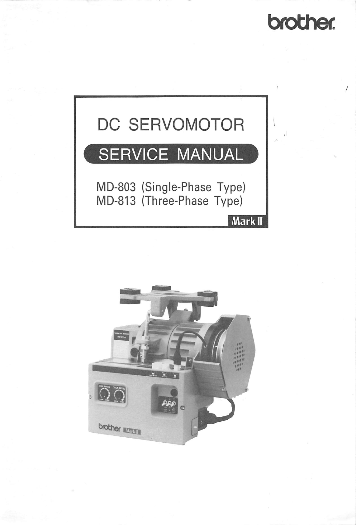
brothec
DC
SERVOMOTOR
MD-803
l\/ID-813
(Single-Phase Type)
(Three-Phase Type)
""I.
•g
^*«her
K93S1I
Page 2
INTRODUCTION
This service manual is compiled forthe technical staff responsible for maintaining
automatic
Read
thread
trimming machine.
the
service manual carefullysothat you
DESCRIPTION
SPECIFICATIONS
NAME
PRINCIPLE
OF
EACH
OF
The
manual
TABLE
OF
THE
PART
CONTROL
describes
understand
OF
MOTOR
SYSTEM
the
motor
and
the
right handling
CONTENTS
CONFIGURATION
COMPATIBILITY
(except
MOTOR
OPERATION
OPERATION
ADJUSTMENT
B738
OF
MD-802,
or
B7380) 7
812
AND
MD-803,
PANEL
INSTRUCTION
TROUBLESHOOTING
CHECKING
CHECKING
PARTS
SPEED
NOTES
DC
MOTOR
CONTROL
CONTROL
TIMING
BLOCK
DETAILS
TIMING
HIC
CIRCUIT
FRAME
INSTALLATION
USING
USING
THE
THE
CODE
NOS.
ADJUSTMENT
REGARDING
TROUBLESHOOTING
BOX
TROUBLESHOOTING
BOX
TROUBLESHOOTING
CHART
DIAGRAM
OF
CONNECTOR
CHART
ASSEMBLY
THE
THE
OF
DIAGRAM
OF
MATERIAL
PRODUCTION
MOTOR
MACHINE
FOR
FOR
DC
OF
CONTROL
OP.
#2
REPLACEMENT
OPTIONS
SOLENOIDS
SPACE
EACH
MOTOR
PANEL
PANEL
EDGE
QUANTITY
PARTS
MACHINE
INSTALLATION
GUIDE
GUIDE
GUIDE
CIRCUIT
E-40
SENSOR
COUNTER
and
inspecting the drive motor
the
control box
and
adjustment.
813
OUTLINE
DETAILS
and
also
covers
1
2
3
5
6
8
8
9
10
17
18
19
20
22
24
25
34
35
57
58
60
73
77
80
84
91
92
designed
adjustments.
for
the
Page 3
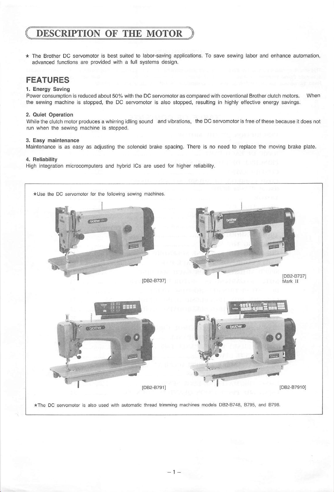
★
The
Brother DC servomotor is
advanced
functions
are
best
suited to labor-saving applications. To
provided with a full
systems
design.
FEATURES
1.
Energy
Power consumption is
the sewing machine is stopped, the DC servomotor is
2.
Quiet
Whilethe clutch motor produces a whirring idling sound
run
3.
Easy
Maintenance isaseasyasadjusting the solenoid brake spacing.
4.
Reliability
High integration microcomputers
when
maintenance
Saving
Operation
the
sewing
reduced
machineisstopped.
about
and
50%
hybrid ICs
with the DC servomotorascompared
also
stopped, resulting in highly effective
and
vibrations, the DC servomotor is free of
are
used
for higher reliability.
There
save
sewing labor
and
enhance
with coventional Brother clutch motors.
energy
these
becauseitdoes
is no
needtoreplace
the
moving brake plate.
automation,
When
savings.
not
★The
DC servomotor is also
wotref
•
used
with
automatic
[DB2-B791J
thread
trimming
machines
models
A;
DB2-B748,
•iflrL'^SlIiLSS
8795,
and
B798.
[DB2-B7910]
Page 4
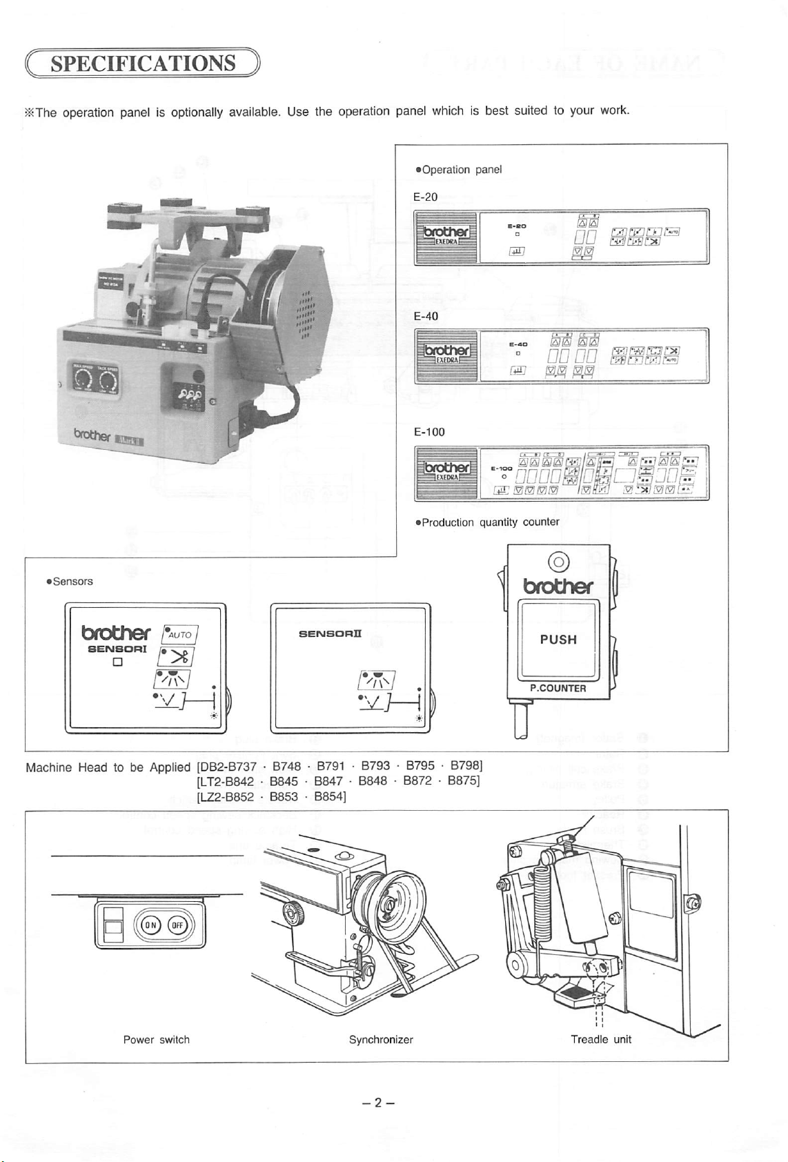
SPECIFICATIONS
J«The
operation panel is
optionally
available.
Use the operation panel
which
is best suited to your
Operation panel
work.
Machine
Head to be
Applied
.
[DB2-B737
[LT2-B842
[L22-B852 • B853 • B854]
• B748 •
• B845 • B847 • B848 • B872 • B875]
B791
Production quantity
• B793 • B795 •
counter
P.COUNTER
B798]
i
Power
switch
Synchronizer
Treadle
unit
Page 5
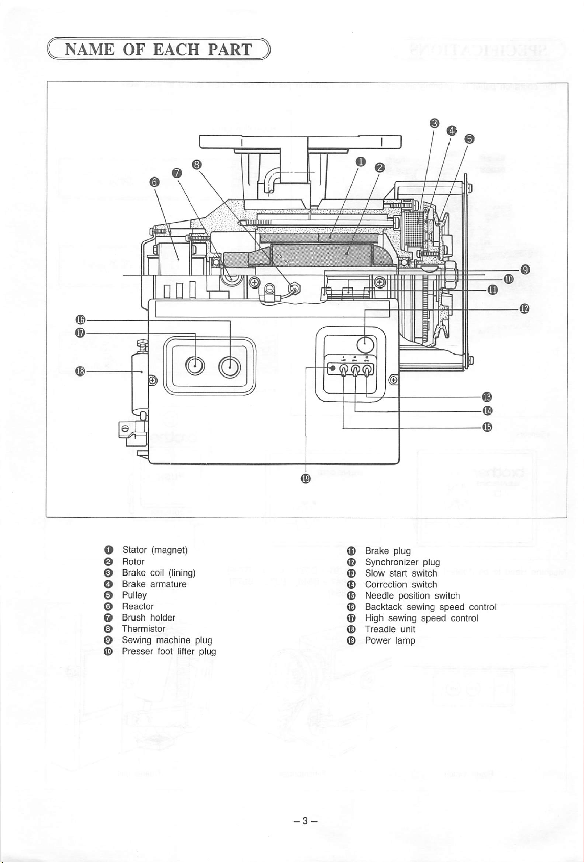
NAME
OF
EACH
PART
Stator (magnet)
Rotor
Brake
coil (lining)
Brake
armature
Pulley
Reactor
Brush
holder
Thermistor
Sewing machine plug
Presser
foot lifter plug
Brake
plug
Synchronizer plug
Slow
start
switch
Correction
Needle
Backtack
High
Treadle
position
sewing
sewing
unit
switch
speed
Power lamp
switch
speed
control
control
Page 6
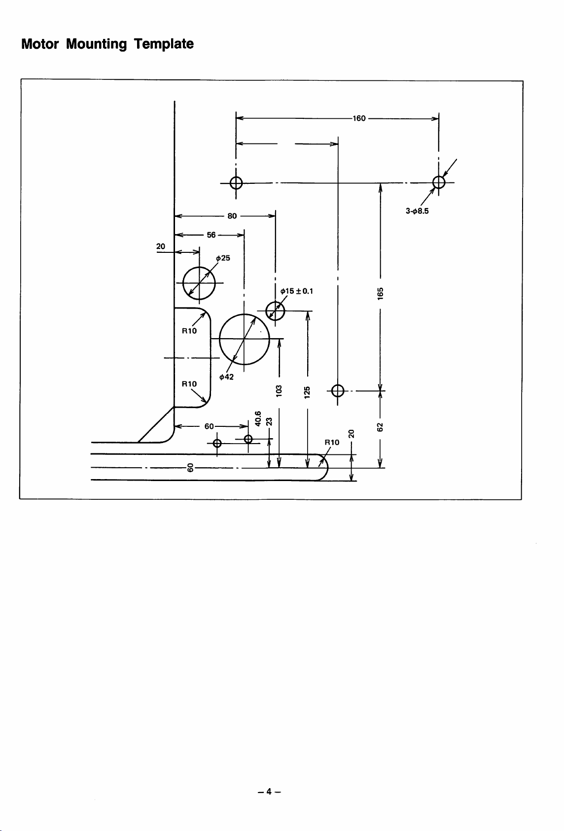
Motor
Mounting
Template
160
80
20
RIO
RIO
01510.1
CO
in
O CO
60
(O
^ CN
RIO
in
-4-
Page 7
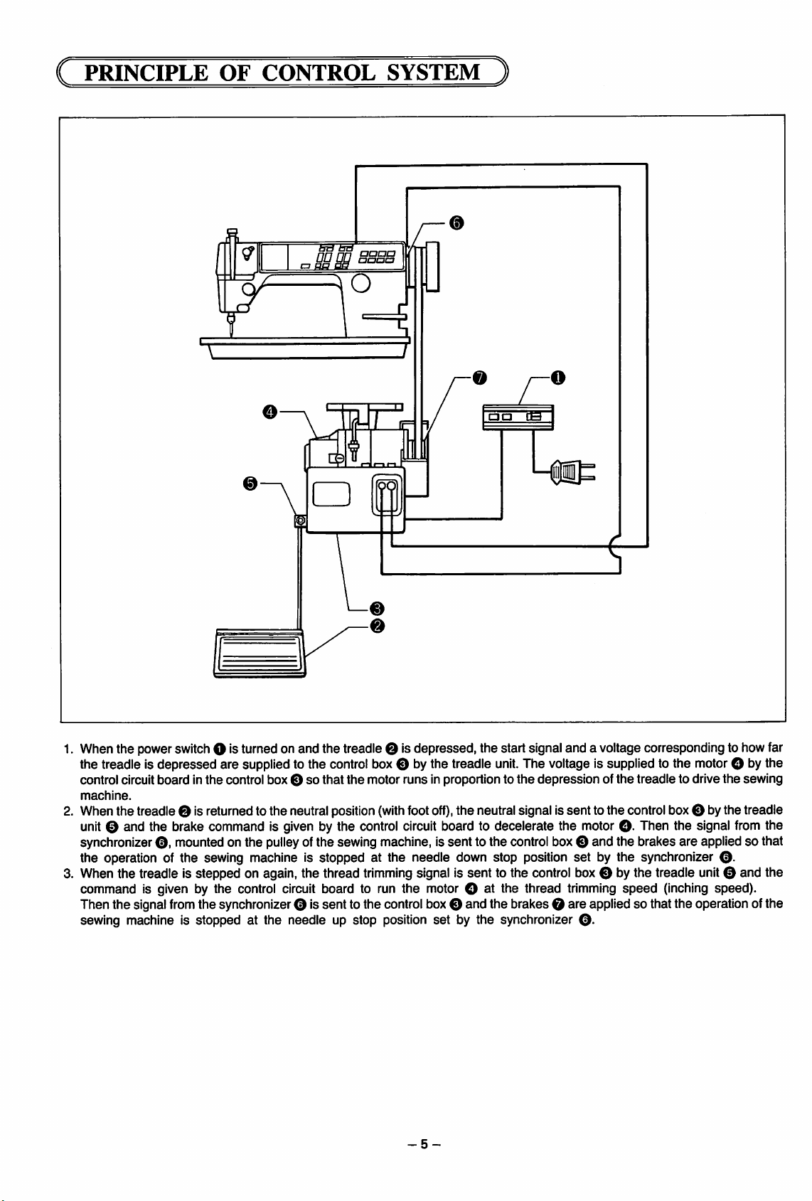
C PRINCIPLE OF CONTROL
m
aa
p
aa
SYSTEM
)
gg
CB
1. When the powerswitchO is turned on and the treadle O Isdepressed, the start signal and a voltage corresponding to how far
the treadle Is depressed are suppliedto the control box O by the treadle
control circuit board Inthe control box Osothat
machine.
2. When the treadle 0 Isreturnedto the neutralposition
the
motor runs Inproportion to
(with
foot
off),
unit.
The voltageIs supplied to the motorO by the
the
depression of
the
treadle to drive the sewing
the neutral signal Issent to the controlboxO bythetreadle
unit 0 and the brake command Is given by the control circuit board to decelerate the motor O- Then the signal from the
synchronizer
the operation of the sewing machine Is stopped at the needle down stop position set by the synchronizer
3. When the treadle Is stepped on again, the thread
command Is given by the control circuit board to run the motor O at the thread trimming
O,
mounted on the pulleyof the sewing machine. Issent to the controlbox O and the brakes are applied so that
O.
trimming
signal Is sent to the control boxO by the treadle unit0 and the
speed
(Inching speed).
Then the signalfromthe synchronizer 0 Issent to the controlbox0 and the brakes O are applied so that the operation of the
sewing machine Is stopped at the needle up stop position set by the synchronizer
-5-
0.
Page 8
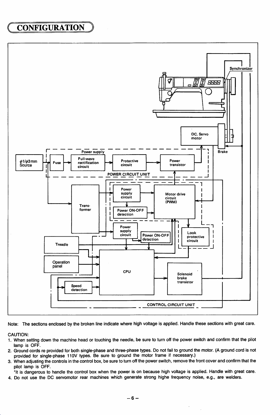
CONFIGURATION )
anon
gP
DC.
motor
bdbd
BS
Servo
O
aaaa
Synchronizer
auaa
61/03 mm
Source
r
I
Mt-
I
I
Fuse
Treadle
Operation
panel
Full-wave
rectification
circuit
Trans
former
Speed
detection
Power
supply
Protective
circuit
POWER
CIRCUIT
Power
supply
circuit
Power
detection
ON-OFF
UNIT
Motor
circuit
(PWM)
^ — ——/5
Power
supply
circuit
CPU
Power
detection
ON-OFF
Power
transistor
drive
5^
Solenoid
brake
transistor
Look
protective
circuit
Brake
I
L_.
CONTROL
CIRCUIT
UNIT
Note: The sections enclosed by the broken line indicate where high voltage is applied. Handle these sections with great care.
CAUTION:
1. When setting down the machine head or touching the needle, be sure to turn offthe power switch and
confirm
that the
lamp is OFF.
2. Groundcords re providedforboth single-phase and three-phase types. Do not
provided
for
single-phase
110V
types.
Be sure to
ground
the
motor
3. Whenadjustingthe controlsinthe controlbox, be sure to tum offthe powerswitch,removethe
fail
to ground the motor. (Aground cord is not
frameifnecessary.)
front
cover and
confirm
pilot lamp is OFF.
*lt
is dangerous to handle the control boxwhen the power is on because high voltage is applied. Handle
4. Do not
use
the
DC
servomotor
rear
machines
which
generate
-6-
strong
highe
frequency
noise,
e.g.,
are
with
great care.
welders.
pilot
that the
Page 9
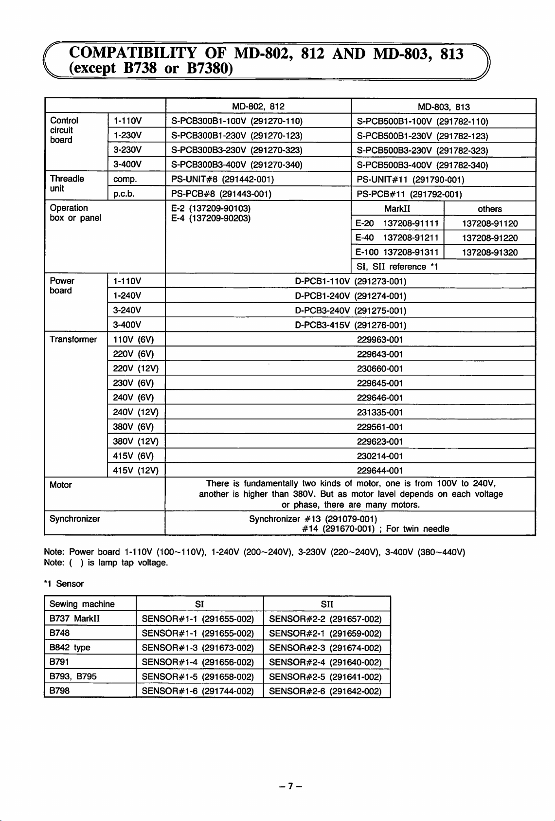
f COMPATIBILITY OF MD-802, 812
V
(except
B738
or
B7380)
AND
MD-803,
813
Control
circuit
board
Threadle
unit
Operation
box or panel
Power
board
Transformer
Motor
Synchronizer
1-110V
1-230V
3-230V
3-400V
comp.
p.c.b.
1-110V
1-240V
3-240V
3-400V
110V
(6V)
220V
(6V)
220V
(12V)
230V (6V)
240V
(6V)
240V (12V)
380V
(6V)
380V
(12V)
415V (6V)
415V
(12V)
S-PCB300B1
MD-802,
-1OOV
812
(291270-110)
S-PCB300B1-230V (291270-123)
S-PCB300B3-230V (291270-323)
S-PCB300B3-400V (291270-340)
PS-UNIT#8
PS-PCB#8
(291442-001)
(291443-001)
E-2 (137209-90103)
E-4 (137209-90203)
There
is fundamentally two kinds of motor,
anotherishigher
than
380V. Butasmotor lavel
or
phase,
Synchronizer
S-PCB500B1 -1
S-PCB500B1-230V (291782-123)
S-PCB500B3-230V (291782-323)
S-PCB500B3-400V (291782-340)
PS-UNIT#11 (291790-001)
PS-PCB#11
Markll
E-20
137208-91111
E-40
137208-91211
E-100
137208-91311
SI,
SII
reference
D-PCB1-110V (291273-001)
D-PCB1-240V (291274-001)
D-PCB3-240V (291275-001)
D-PCB3-415V (291276-001)
229963-001
229643-001
230660-001
229645-001
229646-001
231335-001
229561-001
229623-001
230214-001
229644-001
one
there
are
many
motors.
#13
(291079-001)
#14
(291670-001):For
MD-803,
OOV
813
(291782-110)
(291792-001)
others
137208-91120
137208-91220
137208-91320
*1
is from 100V to 240V,
depends
twin
on
needle
each
voltage
Note: Power board 1-110V
Note: ( ) is lamp
*1
Sensor
tap
Sewing machine
B737
Markll
B748
B842
type
B791
B793,
B795
B798
(100-110V),
voltage.
SENS0R#1-1
SENS0R#1-1
SENS0R#1-3
SENS0R#1-4
SENS0R#1-5
SENS0R#1-6
1-240V (200~240V), 3-230V (220~240V), 3-400V (380~440V)
SI
(291655-002)
(291655-002)
(291673-002)
(291656-002)
(291658-002)
(291744-002)
SENSOR#2-2
SENS0R#2-1
SENSOR#2-3
SENSOR#2-4
SENSOR#2-5
SENSOR#2-6
-7-
SII
(291657-002)
(291659-002)
(291674-002)
(291640-002)
(291641-002)
(291642-002)
Page 10
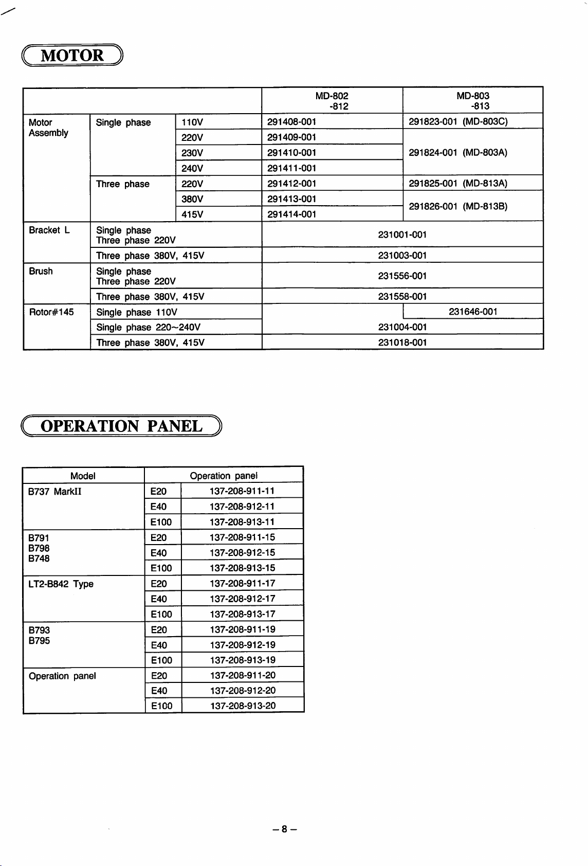
i MOTOR )
Motor
Assembly
Bracket
Brush
Rotor#145
MD-802
-812
phase
Single
Three
phase
L
Single
phase
Three
phase
Three
phase
Single
phase
Three
phase
Three
phase
Single
phase
Single
phase
Three
phase
110V
220V
230V
240V
220V
380V
415V
220V
380V,
415V
220V
380V, 415V
110V
220~240V
380V,
415V
291408-001
291409-001
291410-001
291411-001
291412-001
291413-001
291414-001
291823-001 (MD-803C)
291824-001 (MD-803A)
291825-001
291826-001
231001-001
231003-001
231556-001
231558-001
231004-001
231018-001
MD-803
-813
(MD-813A)
(MD-813B)
231646-001
( OPERATION PANEL )
00
00
00
00
00
Operation
137-208-911-11
137-208-912-11
137-208-913-11
137-208-911-15
137-208-912-15
137-208-913-15
137-208-911-17
137-208-912-17
137-208-913-17
137-208-911-19
137-208-912-19
137-208-913-19
137-208-911-20
137-208-912-20
137-208-913-20
B737
Markll
B791
B798
B748
LT2-B842
B793
B795
Operation
Model
Type
panel
E20
E40
El
E20
E40
El
E20
E40
El
E20
E40
El
E20
E40
El
panel
-8-
Page 11
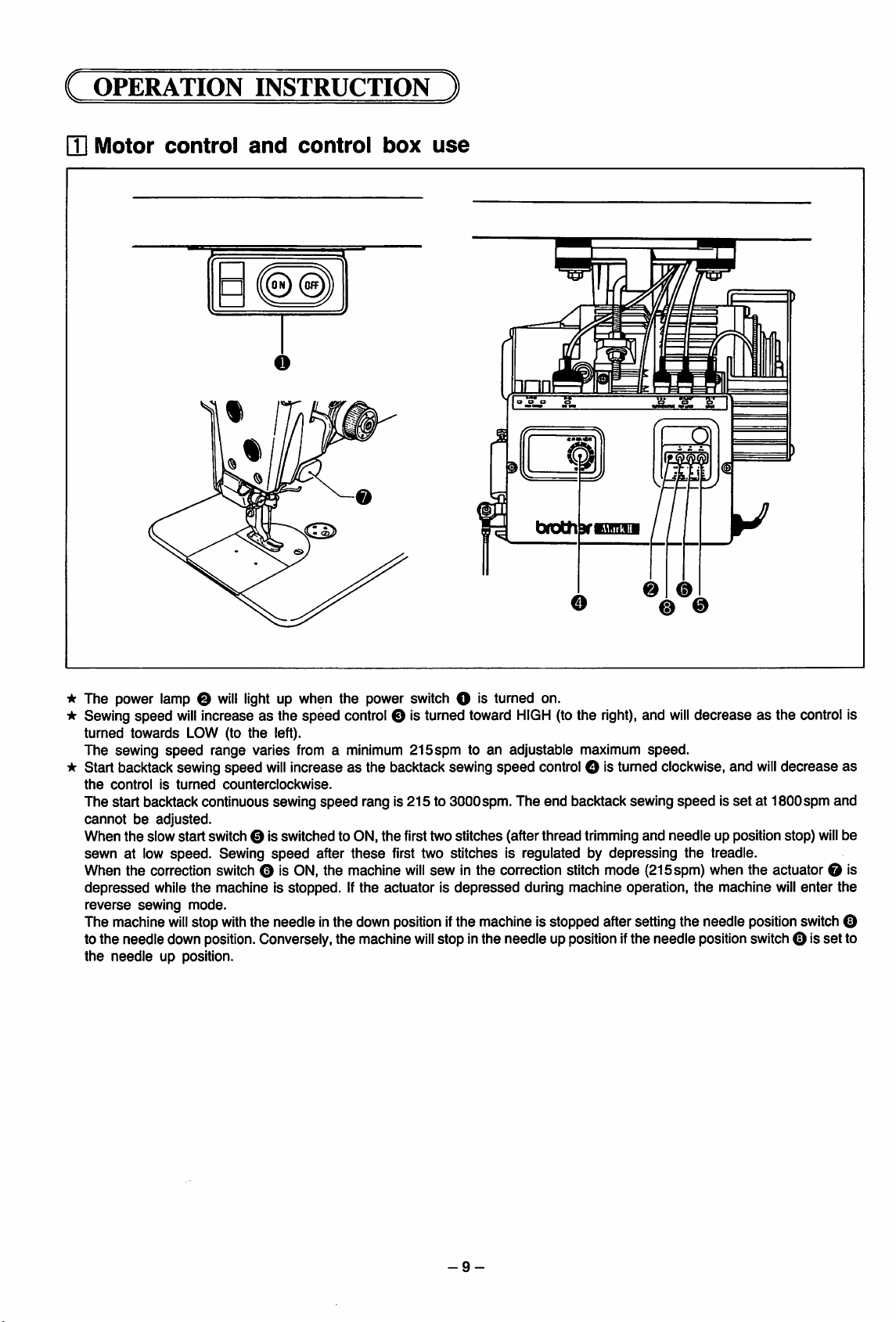
(
OPERATION
[U
Motor
control
INSTRUCTION
and
ONI
o
control
(OFF
box
)
use
tDDl
o o o o
oiocn
ycsssm
-At
The power lamp O
•k Sewing speed
turned
towards
The sewing
-k Start backtack sewing speed
the
controlisturned
The start backtack continuous sewing
cannotbeadjusted.
When
sewn
When the correction switch 0 is ON, the machine
depressed
reverse
The machine
to the needle down position. Conversely,the machine
the
needle
the
slow
at low
sewing
speed
speed.
while
will
up position.
will
light up when the power switch O is turned on.
will
increaseasthe speed control O is turned toward
LOW (to
start
the
mode.
stop
the
left).
range varies from a minimum 215spm to an adjustable maximum speed.
will
increaseasthe backtack sewing speed control O is turned clockwise, and
counterclockwise.
speed
rang is 215 to 3000spm. The end backtack sewing
switch 0 is switched to ON,
Sewing
machine is stopped. If
with
speed
after
these
the
the needle inthe down positionifthe machine is stopped after setting the needle positionswitch0
I
right),
0
and
and
o
HIGH
(to the
the
first two
first two stitches is regulated by depressing
will
actuator is
stitches
sew
depressed
will
stop inthe needle up positionifthe needle positionswitchO<sset to
(after
thread
trimming
in the correction stitch mode (215spm) when the actuator 0 is
during machine operation,
@ 0
will
decreaseasthe control is
will
speedisset
needle
the
the
at 1800spm and
up position stop)
treadle.
machine
decrease
will
enter
will
as
be
the
-9-
Page 12
i
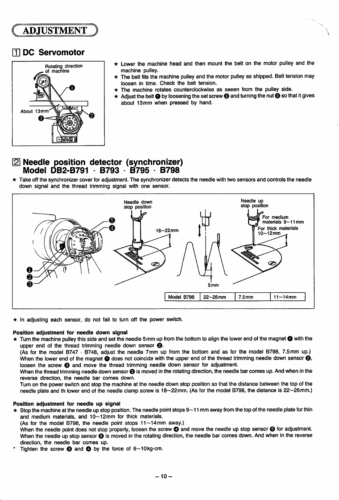
ADJUSTMENT
)
[U DC
About13mm
Needle
Model
★
Take
down signal
Servomotor
Rotatinq
of
machine
0
position
DB2-B791
off
the
synchronizer
and
the
direction
thread
detector
•
B793
cover
for adjustment.
trimming signal with
Lower
the
machine
machine
pulley.
head
and
then
mount
the
belt on
the
motor pulley
and
the
The belt fitsthe machine pulleyand the motor pulleyas shipped. Belttension may
loosenIntime.
The
machine rotates counterclockwiseasseeen
Adjust
the
about
13 mm
belt
Check
O by
when
the
loosening
pressed
belt
tension.
theset screw0 and
by hand.
from
the
pulley side.
turning
thenut0 sothatItgives
(synchronizer)
•
B795
The
Needle
stop
position
•
B798
synchronizer
one
sensor.
down
18-22
detects
mm
the
needle
I]"
with two
sensors
Needie up
stop
and
controls
position
For
medium
materials
'For thick materiais
10~12mm
9~11mm
the
needle
11—14mm
* In adjusting
Position
★
Tumthe machine
each
adjustment
upper end of the thread
Model
sensor, do not fall to turn off the power switch.
for
needle
pulley
thisside and set the needle5mm up
down
trimming
signal
needle down sensor
from
0.
B798
the
bottomtoalign
22-26
mm
the
7.5
mm
lower
end ofthe magnetO
(As for the model 8747 • 0748, adjust the needle 7 mm up from the bottom andasfor the model 8798, 7.5mm up.)
When
the
lower
loosen
the
end ofthe magnetO does not
screw 0
and
move
the
thread trimming needle down
coincide
with
the upperend of the thread
sensor
for adjustment.
trimming
needle
down
sensor
When the thread trimming needle down sensor0 Ismoved Inthe rotating direction, the needle bar comes up.And when Inthe
reverse
direction,
the
needle
bar
comes
down.
Turnon the power switchand stop the machine at the needle downstop position so that the distance between the top ofthe
needle plate and th lowerend of the needle clamp screw Is 18~22mm. (Asfor the model 8798, the distance Is22~26mm.)
Position
★
adjustment
for
needie
up
signal
Stopthe machineatthe needleupstop
and
medium materials,
and
10—12mm
position.
The needle pointstops
for thick materials.
9—11
mmaway
from
the topofthe needle plateforthin
(As for the model 8798, the needle point stops 11—14mm away.)
When
the needle
point
does notstop
properly,
loosenthe screwO and movethe needie up stop sensor 0 foradjustment.
When the needle up stop sensor 0 Is moved Inthe rotatingdirection, the needle bar comes down. Andwhen Inthe reverse
direction,
the
needle
bar
comes
up.
• Tighten the screw 0 and O by the force of 6—lOkg-cm.
with
the
0,
-10-
Page 13
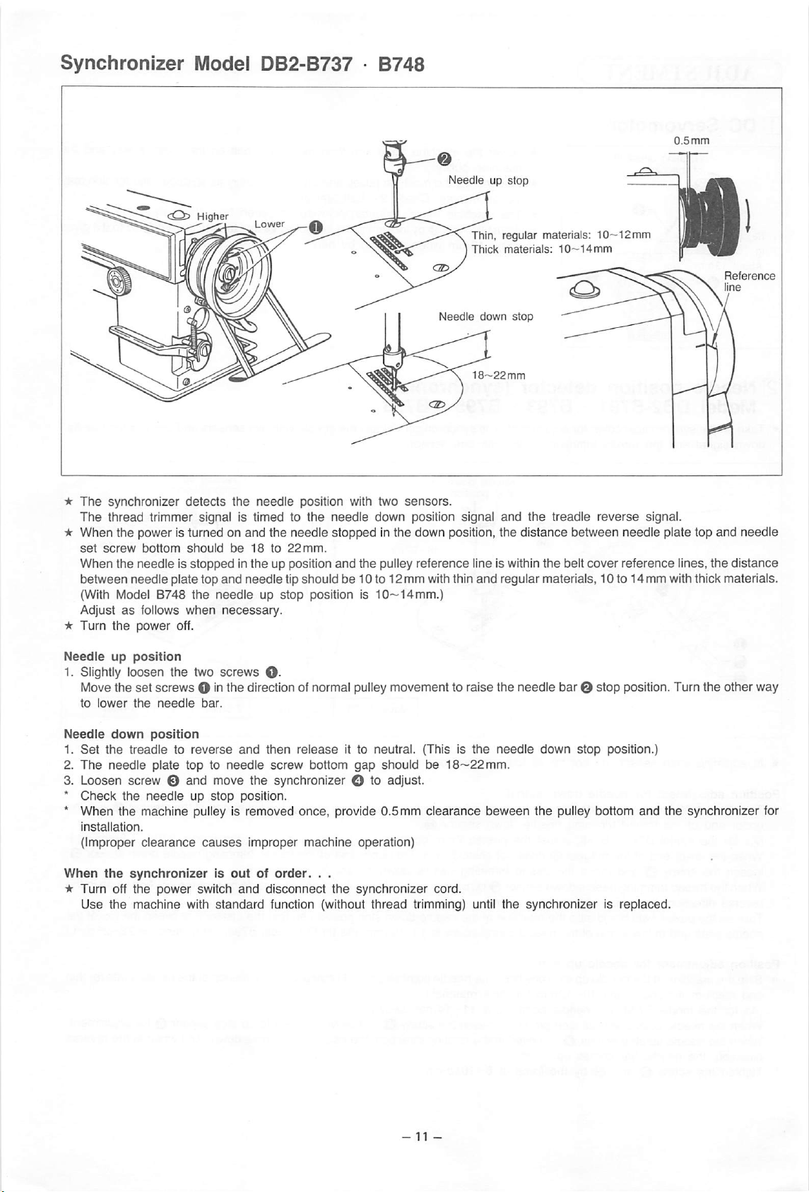
Synchronizer
Model DB2-B737 •
B748
18--22
mm
Reference
e
★
The
synchronizer
The
thread trimmer signal is timed to the
★
When the power is turned on and the needle stopped in the down position, the distance between needle plate top and needle
set
screw
When the needle Is
between
needle
(With Model B748
Adjustasfollows
★
Turn
the
power
Needle
up
position
1. Slightly loosen the two screws
Move the
to
Needle
1.
Set
The
2.
set
lower
the
down
the
treadletoreverse
needle
bottom
detects
should
plate top
when
the
be
stopped
in the up position
and
the
needleupstop
necessary.
needle
18to22mm.
needle
position with two
needle
down position signal
and
the pulley reference line is within
tip should be 10 to 12 mm withthin
position is
10~14mm.)
sensors.
and
the treadle
the
and
reguiar materials, 10 to 14 mm withthick materials.
belt
reverse
cover
signal.
reference
lines, the
distance
off.
O-
screws O inthe direction of normal pulley movement to raise the needle bar O stop position. Turn the other way
needle
position
plate top to
bar.
and
needle
then
screw
release
bottom
it to neutral. (This is
gap
should
be
18—22mm.
the
needle
down
stop
position.)
3. Loosen screw and move the synchronizer O to adjust.
★
Check
the
needleupstop
★
When the machine puliey is removed
installation.
(Improper
When
★
Turn
Use
clearance
the
synchronizerisoutoforder.
off
the
power
switch
the
machine
with
causes
standard
position.
improper
and
disconnect
function (without
once,
machine
. .
provide
operation)
the
synchronizer
0.5mm
thread
clearance
cord.
trimming) until
beween
the
pulley bottom
the
synchronizerisreplaced.
and
the
synchronizer for
-11-
Page 14
[^Control
Control
The high
box
speed
box
(Model DB2-B737)
volume, backtack stitch volume, power lamp, needle position switch, one-stitch modification switch, slow start
switch and connector for synchronizer
control
The
The
The
three-phase
The
*Do not fail to
•Never
circuit
board.
control
power
right
control circuit board is provided with
circuit
boardisinstalled
circuit
board
side
wall is furnished with
type
and
secure
short-circuit
the
two
the
is at
3A
fuse
lamp
the
fuses
holder
terminal
are
arranged on the front of
on
the
insideofthe
back
and
the
treadle
one
15A fuse for
for 380—440V
the
8A
cap
after replacing or inspecting
(AC6Vor
the
control box.
control
unit is on
the
three-phase
fuse
for solenoid load.
12V
terminal)Wlighting,orthe
box.
the
110~240V
type.
single-phase type, two 5A
left
the
side
fuses.
All
these
wall.
transformer
parts
are
fuses
maybebroken.
already provided on the
for
the
200~240V
Control
Explanationofeach
*Do not turn
Model
1.
2.
circuit
the
volume knobs when not necessary.
B737•B748•B791•B793•B795•B798
Take
off
the
When
the
LOW VR O (low
volume
front
board
knob
cover.
speed
thread trimming) is turned clockwise, the
low machine
creases.
3. When
the
speed
is adjusted to in
EBT VR O (end backtacking
speed) is turned clockwise, the backtack
ing
speedisadjustedtoincreases.
4.
The
SBT
VR O is
and
continuous backtacking
volume.
start
backtacking
speed
5. The HIGH VR O is high sewing
adjust volume.
6.
The
AUTO VR 0 is
speed
adjust volume.
automatic
7. The SLOW VR 0 is slow start
adjust
volume.
8. When the
is
turned
VR1
O is (brake-offtimming set)
clockwise,
the
brake
adjusted to increase. And when counter
clockwise, it is
adjustedtodecrease.
9. When the TVR0 (torque setting) is turned
clockwise, the torque is adjusted to in
creases.
and
speed
adjust
speed
sewing
speed
force is
AUTO 0
Automatic
speed
LOW O
Low
speed
EBT 0
Backtacking
speed
SLOW ©
TVR ©
Torque
setting
m
Brake-off
time setting
CAUTION:
Other volume knobs are factory set, so that they never require adjustment.
Note 1: Itis dangerous to touch the volumeknobs by finger because highvoltage is applied. Do not
fail
to turn offthe power
switch before adjustment. To check the setting, tum it on again.
Note 2: Take care that the driverdoes not touch other parts but the volume knobs for adjustment. Adjustthe volumeknobs
great care. They may be broken if turned past the stop point.
Note 3: When any volume knob is turned by mistake, turn it back so that the red indexes match
-12-
with
each other.
with
Page 15
Explanation
each
dip
switches
Dip A
1
2 Position of
3 Position of
4
5
6
7
8
Position of
thread
presser
trimming
presser
thread
trimming with
at
neutral
presser
machineisstopped
treadle
Double
Double
AB-i-10
CD-I-10
Continuous
selection
at
neutral
start
end
backtack
backtack
backtack
backtack
backtack
after
after
treadle
when
with
ON
OFF
ON
OFF
ON
OFF
ON
OFF
ON
OFF
ON
OFF
ON
OFF
ON
OFF
Down
Raised
Raised
Down
Raised
Down
Double
Single
Double
Single
10
stitches
Seam
10
stitches
Seam
A-l-C, B-i-C,
A, B, C, D
Dip B
1
2
3
4
5 Normally ON
6
Start
Start
stitch
Actuator
Unused
backtack
and
End
number
switch
selection
backtack
ON
OFF
ON
OFF
ON
OFF
Normally
Stops
Sews
to
Fixed 4-stitches setting
Fixed
at4stitches
Thread
none
start
backtack
start
backtack
end
backtack
end
backtack
addedtothe
AB
sewnasdisplayed
addedtothe
CD
sewnasdisplayed
sewn
(W)
(V)
(W)
(V)
displayed
displayed
repeatedlyDtimes
OFF
when
treadle
endofB
is returned to neutral
when
treadle
becomes
trimming controllable with
AB
seam
CD
seam
isatneutral
variable with
actuator
length
length
switch
models
E-20, E-40
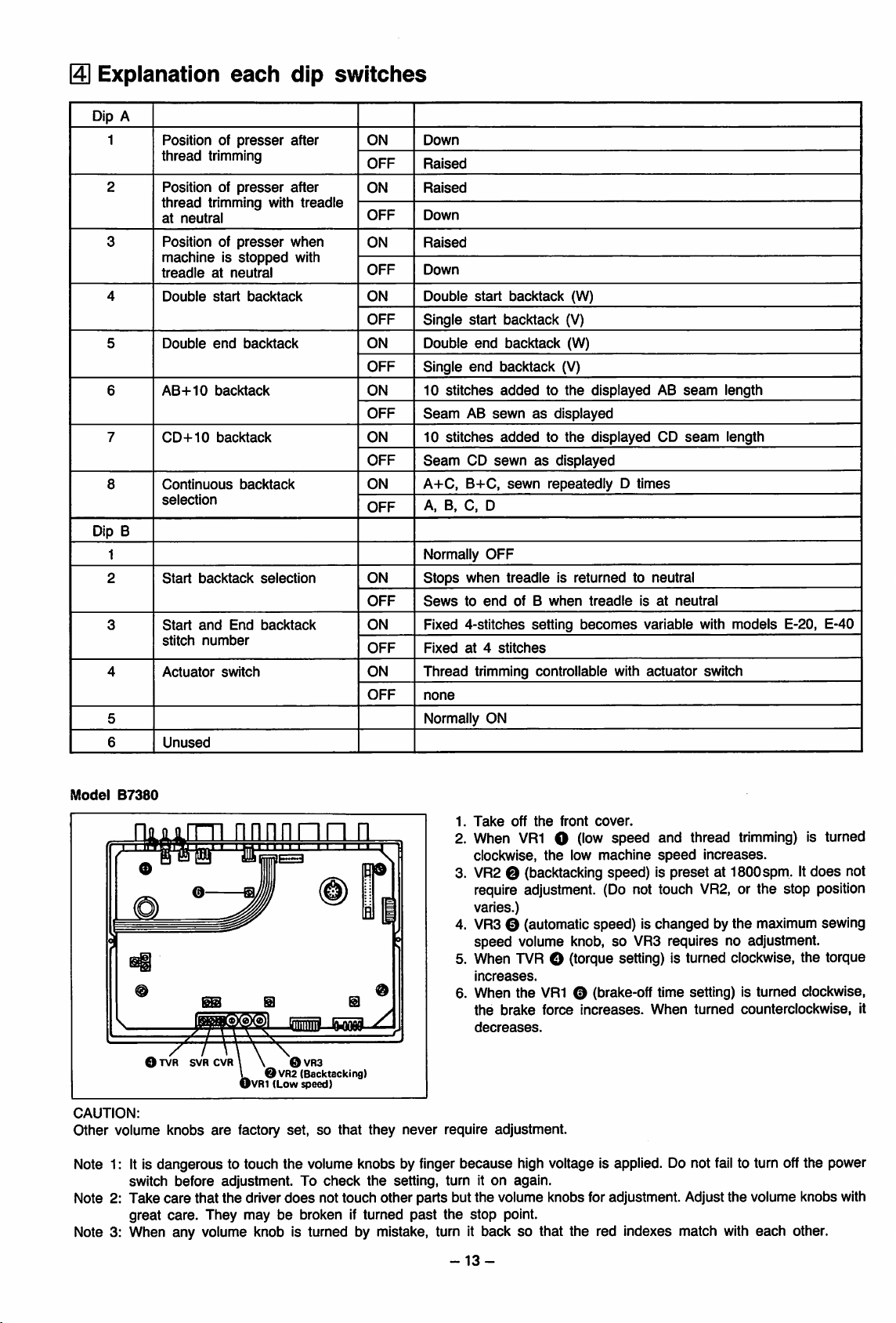
Model
B7380
1.
Take
off
the
front
cover.
mnn
n
2. When
VR1
O (low speed and thread trimming) is turned
clockwise, the low machine
speed
increases.
3. VR2 O (backtacking speed) is preset at ISOOspm. It
require adjustment. (Do not touch
i
varies.)
4. VR30 (automatic speed) is changed bythe maximum sewing
speed
volume knob,soVR3 requires no adjustment.
VR2,
5. When TVR O (torque setting) is turned clockwise, the torque
increases.
6. When the
the
decreases.
CAUTION:
other
volume knobs
O
SVR
CVR
are
BD
\ \ ©
\ OVR2
OVRI (Low speed)
factory
VR3
(Backtacking)
set,
OS
so that they never require adjustment.
Note 1: It is dangerous to touch the volume knobs by finger because high voltage is applied. Do not
switch before adjustment. To
Note 2: Take care that the driver
great care. They may be broken if turned
check
the
setting, turn it on again.
does
not touch other parts but the volume knobs for adjustment. Adjustthe volume knobs with
past
the stop point.
brake
VR1
O (brake-off time setting) is turned clockwise,
force
increases.
When
turned
fail
Note 3: When any volume knob is turned by mistake, turn it back so that the red indexes match with
does
not
or the stop position
counterclockwise,
to turn offthe power
each
other.
it
-13-
Page 16
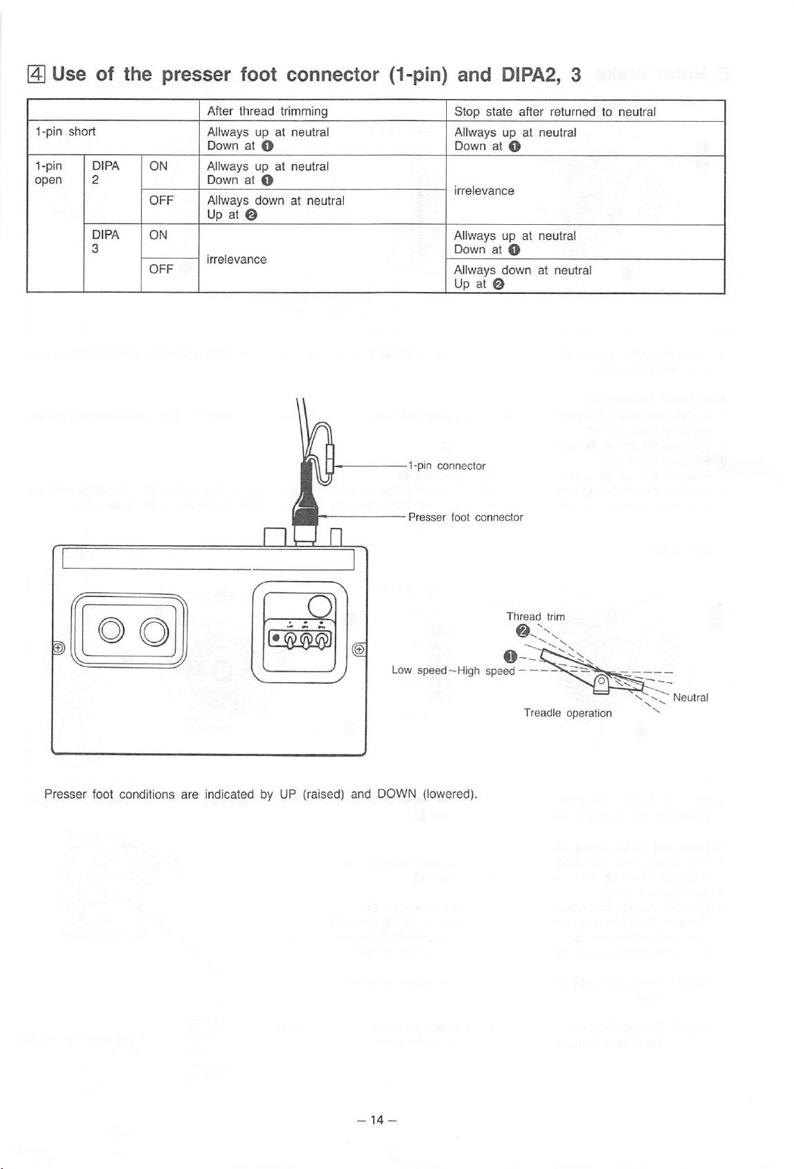
Use
1-pin
1-pin DlPA ON
open
short
of
2
DlPA
3
the
OFF
ON
presser
After
Allways up at neutral
Down
Allways upatneutral
DownatO
Allways
Up at O
irrelevance
foot
thread
at O
down
connector
trimming
at neutral
(1-pin)
1-pin
and
Stop
Allways up
Down at O
irreevance
Allways up at neutral
Down at O
Allways
DIPA2, 3
state
after
at
downatneutral
Up at O
connector
returned
neutral
to neutral
Presser
foot conditions
Presser
Low
are
indicated by UP (raised) and DOWN (lowered).
foot
speed-High
connector
speed
Thread
trim
Treadle
operation
Page 17
Motor
brake
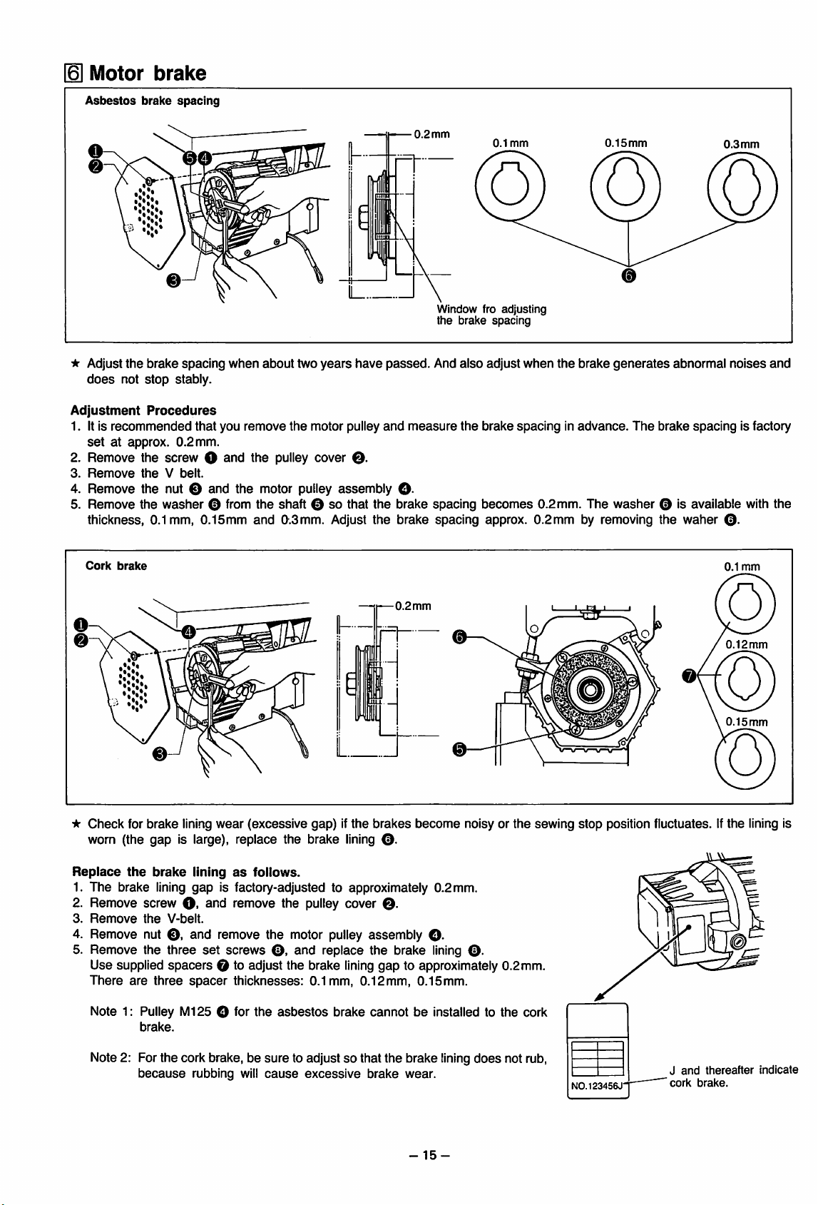
Asbestos
* Adjust
does
Adjustment
1. It is
setatapprox.
2. Remove the screw O
3.
Remove
brake
spacing
the
brake
not
stop
stably.
Procedures
recommended
0.2
theVbelt.
spacing
that
mm.
when
about
you
remove
and
the pulley cover
two
years
the
motor pulley
have
O.
passed.
and
4. Remove the nut O and the motor pulley assembly O-
5. Remove the
thickness, 0.1mm, 0.15mm and
washer
© from the shaft ©sothat
0^.3mm.
Adjust the brake spacing approx. 0.2mm by removing the waher
the
brake spacing
0.2
mm
Window fro adjusting
the brake spacing
And
also
measure
the
0.1
mm
O
adjust
when
brake
spacingInadvance.
becomes
0.2mm. The
the
brake
0.15mm
generates
The
washer
0.3
mm
abnormal
brake
spacing
noises
is factory
and
© is available with the
©.
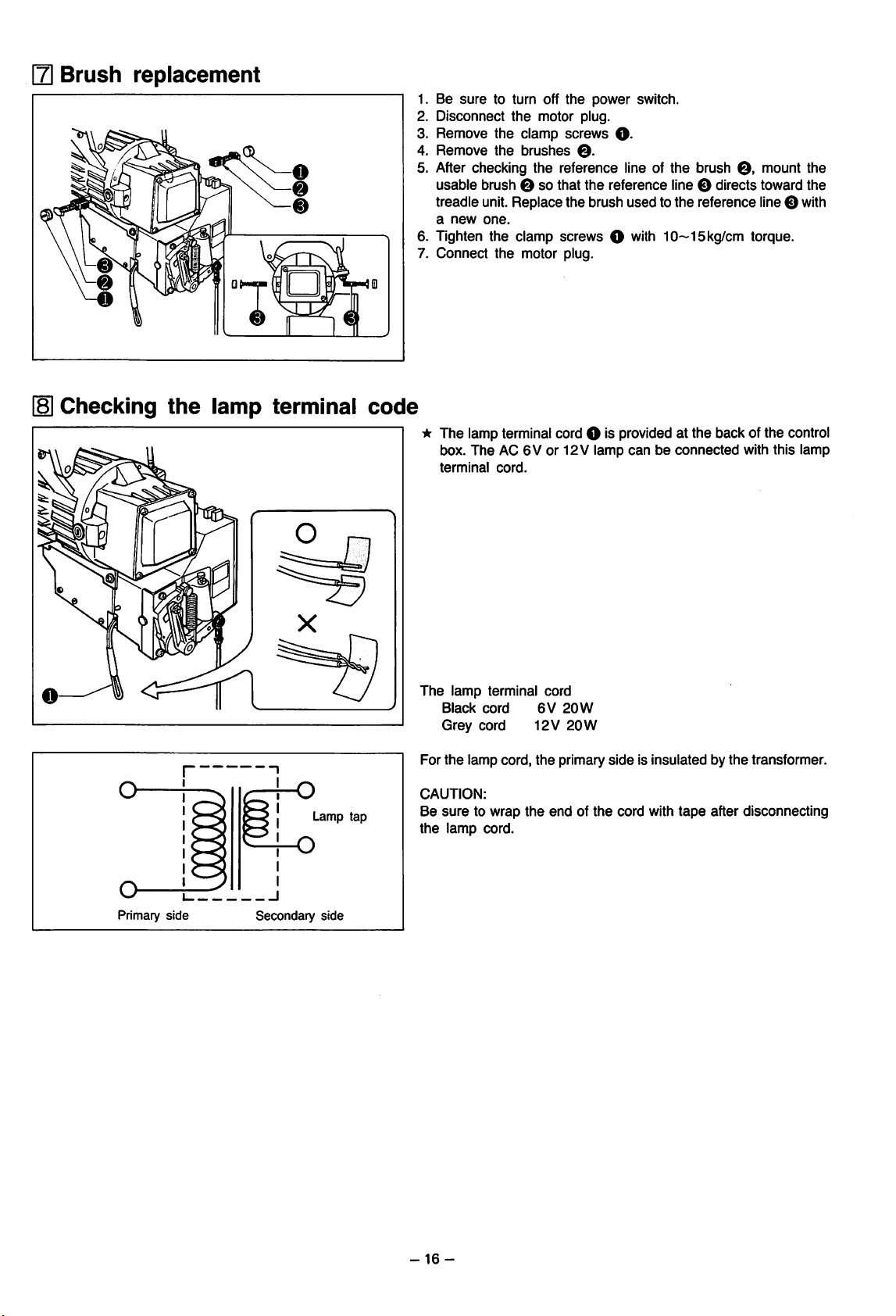
Cork
brake
★
Check
for
brake
lining
wear
(excessive
worn (the gap is large), replace the brake
Replace
1. The brake
2. Remove screw
3.
4. Remove nut
5. Remove the three
Remove
the
brake
the
liningasfollows.
lining
gap is factory-adjusted to approximately 0.2mm.
O.
and remove the pulley cover
V-belt.
©.
and remove the motor pulley assembly
set
screws
©,
Use supplied spacers © to adjust the brake
There
are
three
spacer
thicknesses:
gap)ifthe
lining
and
replace the brake
lining
0.1mm,
-—0.2
mm
brakes
become
noisy or
©.
©.
©.
lining
©.
gap to approximately 0.2mm.
0.12mm,
0.15mm.
the
sewing
stop
position fluctuates. If
0.1
mm
O
0.12mm
0.15mm
0
the
lining is
Note 1: Pulley Ml25 O for
brake.
Note 2: For the cork brake, be
because
rubbing will
the
asbestos
sure
cause
brake cannot be installed to the cork
to adjust so that the brake
excessive
brake
wear.
-15-
lining
does
not rub,
N0.123456J"
J
cork
and
thereafter
brake.
indicate
Page 18
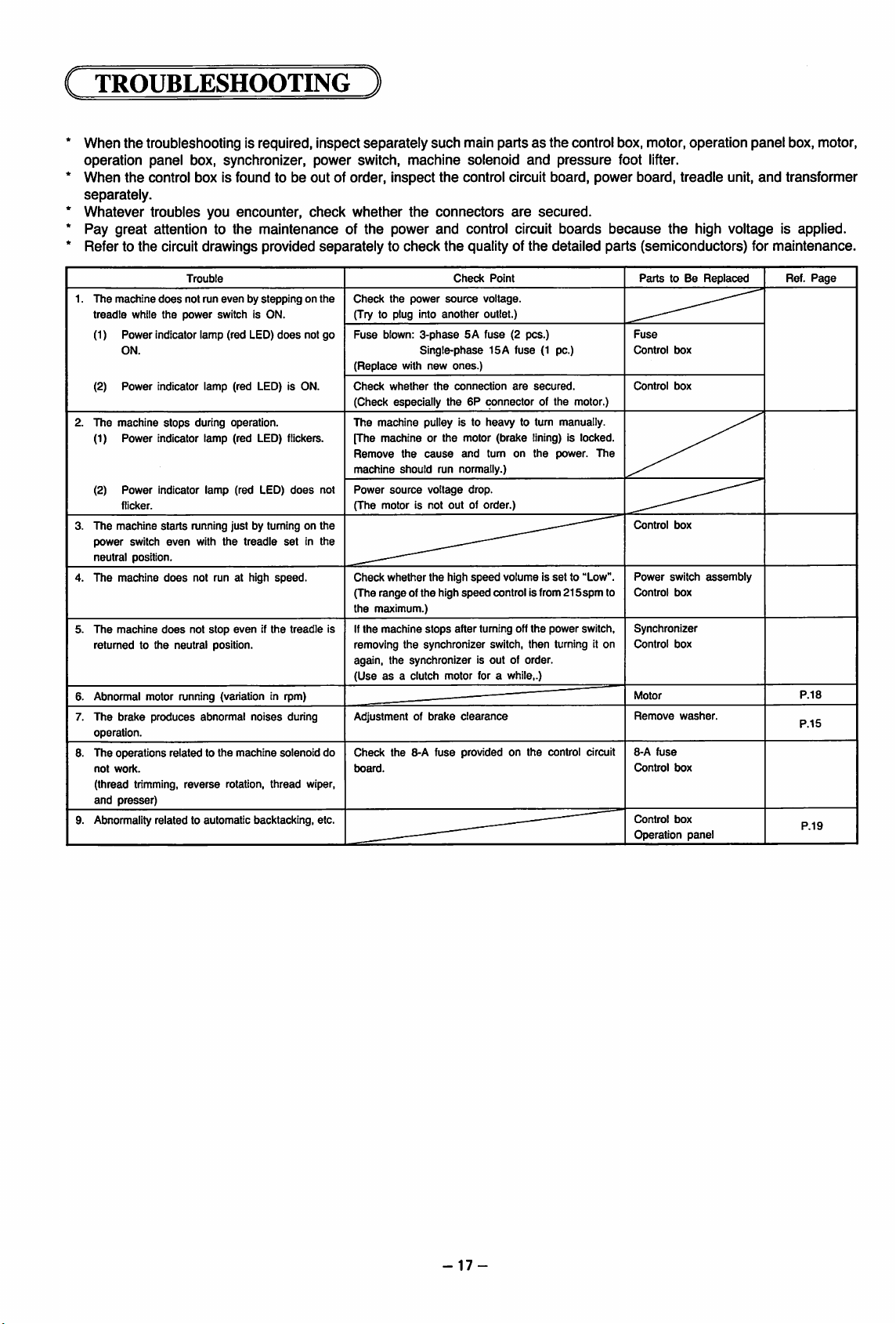
[7|
Brush
replacement
1. Be
sure
to turn off tfie
2. Disconnect tfie motor plug.
3. Remove tfie clamp
4.
Remove
tfie
bruslies
power
screws
©.
switcfi.
O-
5. After cfiecking tfie reference line of tfie brusfi
usable
brusfi Osotfiat tfie
treadle unit. Replace tfie brusfi
a
new
one.
6. Tigfiten tfie clamp screws ©
7. Connect tfie motor plug.
reference
used
witfi
line O directs toward tfie
to tfie reference line©
10~15kg/cm
0,
torque.
mount tfie
witfi
Checking
o
the
lamp
terminal
f-o
Lamp
o
tap
code
* Tfie lamp terminal cord © is provided at tfie back of tfie control
box. Tfie AC 6V or 12 V lamp
terminal
Tfie lamp terminal cord
Black
Grey
For tfie lamp cord, tfie primary
CAUTION:
Be
suretowrap
tfie
lamp
cord
cord
cord.
cord.
tfie
6V
12V
end
20W
20W
of tfie
canbeconnected
side
is insulated by tfie transformer.
cord
witfi
tape
witfi tfiis lamp
after
disconnecting
o
Primary
side
Secondary
side
-16-
Page 19
TROUBLESHOOTING
When
the
troubleshooting is required, inspect
operation panel box, synchronizer, power switch, machine solenoid
When
the
control box is found to be out of order, inspect
separately.
Whatever
troubles
you
encounter,
check
Pay great attention to the maintenance of
Refer to
1.
2. The machine
3. The machine
4.
5.
6. Abnormal motor running (variation in rpm)
7.
8. The operations related to the machine solenoid do
9. Abnormality related to automatic backtacking, etc.
the
circuit drawings provided
The
machine
does
treadle while
(1)
(2)
(1)
(2)
power
neutral position.
The
The
returnedtothe
The
operation.
not
work.
(thread trimming,
and
the
Power
indicator lamp (red LED)
ON.
Power
indicator lamp (red LED) is ON.
stops
Power
indicator
Power
indicator
flicker.
starts
switch
machine
does
machine
does
brake
produces
presser)
Trouble
not run
evenbysteppingonthe
power
switch is ON.
during operation.
lamp
(red LED) flickers.
lamp
(red LED)
running just by tuming on the
even
with
the
treadle
not run at high
not
stop
evenifthe
neutral position.
abnormal
reverse
rotation,
noises
thread
does
does
set
speed.
treadle
during
not go
in the
wiper,
separately
whether
the
separatelytocheck
Check
(Try to plug into
Fuse
blown:
(Replace
Check
(Check especially the 6P connector of the motor.)
The
machine
[The machine or the motor (brake lining) is locked.
Remove
machine
Power
not
(The motor is not out of order.)
Check whether the high
(The
rangeofthe
the
maximum.)
If
the
is
machine
such
main
the
control circuit board, power board, treadle unit,
the
connectors
power
and
control circuit boards
the
quality of
Check
the
power
source
voltage.
another
outlet.)
3-phase5Afuse
Single-phase 15 A fuse (1 pc.)
with
new
ones.)
whether
the
connection
the
should
source
pulley is to
cause
run normally.)
voltage
high
stops
heavy
and
tumonthe
drop.
speed
speed
after tuming off
removing the synchronizer switch, then turning it on
again, the synchronizer is out of order.
(Useasa clutch motor for a while,.)
Adjustment of
Check the 8-A fuse provided on the control circuit
traard.
brake
clearance
_________
partsasthe
and
are
secured.
the
Point
(2 pcs.)
are
secured.
to tum manually.
volume is
control is from
the
control box, motor, operation
pressure
detailed
power.
set
to "Low".
215spm
power switch,
foot lifter.
because
parts
The
to
the
(semiconductors) for maintenance.
Parts
to Be
Fuse
Control
t}ox
Control
box
Control
box
Power
switch
Control
box
Synchronizer
Control
box
Remove
washer.
8-A
fuse
Control
box
Control
box
Operation
panel
panel
box, motor,
and
transformer
high voltage is applied.
Replaced
assembly
Ref.
P.I
Page
5
P.19
-17-
Page 20
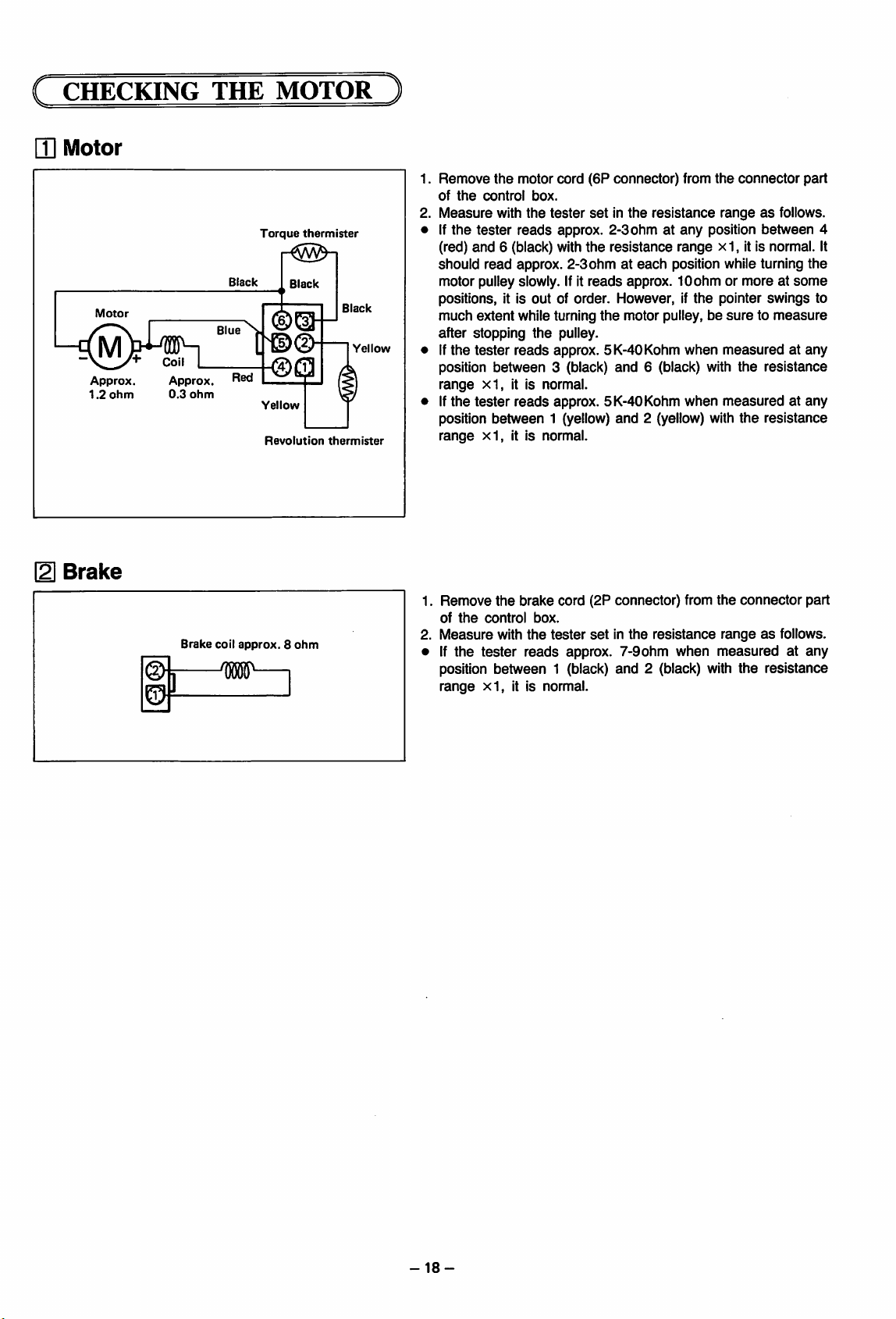
CHECKING
Q]
Motor
THE
MOTOR
Motor
Approx.
1.2
Brake
ohm
Approx.
0.3
ohm
Brake
Black
coil
approx.8ohm
W
Torque
Yellow
Revolution
thermister
Black
Black
Yellow
thermister
Remove
of
Measure
If
(red)
should
motor pulley slowly. If it
the
the
the
motor cord
control
tester
and
read
box.
with
the
reads
6 (black) with the resistance range x 1, it is normal. It
approx.
(6P
connector)
tester
setinthe
approx. 2-3 ohm at
2-3ohmateach
reads
approx. 10
resistance
any
position while turning
positions, it is out of order. However, if
much
extent
while turning
after stopping
If
the
tester
the
reads
position between 3 (black)
range
x1,
it is normal.
If
the
tester
reads
position between 1 (yellow)
range
x1,
it is normal.
Remove
1.
of
2.
Measure
• If
the
the
the
control
with
tester
brake
box.
the
reads
tester
the
motor pulley,besuretomeasure
pulley.
approx. 5K-40Kohm
and
6 (black) with
approx. 5K-40Kohm when
and
2 (yellow) with
cord
(2P
connector)
setinthe
resistance
approx. 7-9 ohm when
position between 1 (black) and 2 (black) with
range
xl,
it is normal.
from
the
connector
rangeasfollows.
position
between
ohmormoreatsome
the
pointer swings to
when
measuredatany
the
resistance
from
measured
the
the
connector
at any
resistance
rangeasfollows.
measuredatany
the
resistance
part
4
the
part
-18-
Page 21
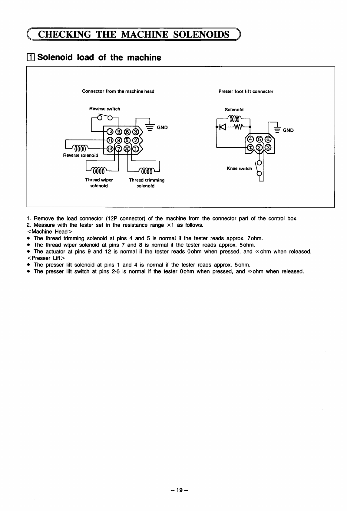
CHECKING
Q]
Solenoid
load
THE
of
MACHINE
the
machine
SOLENOIDS
1.
Remove
2.
Measure
<
Machine
•
The
•
The
•
The
<
Presser
•
The
•
The
Connector
Reverse
Reverse
solenoid
l-W—I
Thread
solenoid
the
load
connector
with
the
tester
Head>
thread
trimming solenoid at pins 4
thread
wiper
solenoidatpins7and
actuator
presser
presser
at pins 9
Lift>
lift solenoid at pins 1
lift switch at pins 2-5 is normal if
from
switch
<5®©i
wiper
(12P
setinthe
and
12
the
machine
®®|®.
—w-l
Thread
solenoid
connector) of
resistance
and
is normal if
and
4 is normal if
head
-=•
GND
trimming
the
machine
range
xl
5 is normal if
8 is normal if
the
tester
the
tester
as
the
reads
the
follows.
the
tester
Oohm
tester
Oohm
from
tester
the
reads
reads
when
reads
when
Presser
foot
Solenoid
[—W—I
Knee
switch
connector
approx.
pressed,
approx. 5ohm.
pressed,
partofthe
approx.
5ohm.
and
lift
connecter
®©®
7ohm.
and
<»ohm
<»ohm
=
GND
control box.
when
when
released.
released.
-19-
Page 22
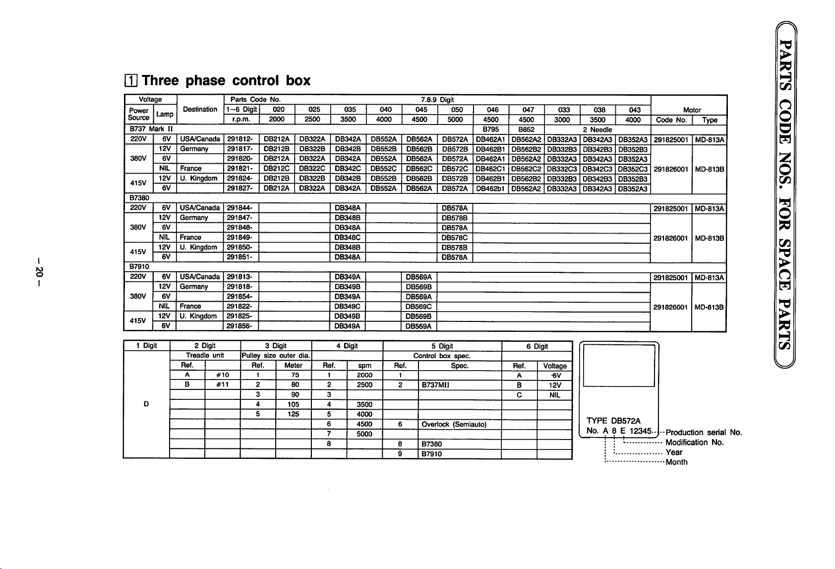
/r\
>
9S
lU
Three
Voltage
Power
Source
B737
Mark
220V
380V
415V
B7380
220V
380V
415V
to
o
B7910
220V
380V
415V
1 Digit
D
La
12V
NIL
12V
12V
NIL
12V
12V
NIL
12V
mp
II
6V
6V
6V
6V
6V
6V
6V
6V
6V
phase
Destination
USA/Canada
Germany
France
U. Kingdom
USA/Canada
Germany
France
U. Kingdom
USA/Canada
Germany
France
U. Kingdom
2 Digit
Treadle
Ref.
A
B
1-6
291812-
291817-
291820291821-
291824-
291827-
291844291847291848291849-
291850291851-
291813-
291818-
291854-
291822-
291825-
291856-
unit
#10
#11
control
Parts
Code
Digit
r.p.m.
DB212A
DB212B
DB212A
DB212C
DB212B
DB212A
3 Digit
Pulley
size
Ref.
1
2
3
4
5
box
No.
020 025 035
2000 2500
DB322A DB342A
outer
Meter
DB322B
DB322A
DB322C
DB322B
DB322A
dia.
75
80
90
105
125
DB342B
DB342A DB552A
DB342C
DB342B DB552B
DB342A
DB348A
DB348B
DB348A
DB348C
DB348B
DB348A
DB349A
DB349B
DB349A
DB349C
DB349B
DB349A
4 Digit
Ref.
1
2
3
4
5
6
7
8
3500
DB552A
DB552B
DB552C
DB552A
spm
2000
2500
3500
4000
4500
5000
040
4000 4500
045
DB562A
DB562B
DB562A
DB562C
DB562B
DB562A
DB569A
DB569B
DB569A
DB569C
DB569B
DB569A
Control box
Ref.
1
2
6 Overlock
8
9
7.8.9
5 Digit
B737MII
B7380
B7910
Digit
050
5000
DB572A
DB572B
DB572A
DB572C
DB572B
DB572A
DB578A
DB578B
DB578A
DB578C
DB578B
DB578A
Spec.
(Semiauto)
spec.
046
4500
B795
DB462A1
DB462B1
DB462A1
DB462C1
DB462B1
DB462b1
047
4500
B852
DB562A2
DB562B2
DB562A2
DB562C2
DB562B2
DB562A2
6 Digit
Ref.
A
B
C
033
3000
DB332A3
DB332B3
DB332A3
DB332C3
DB332B3
DB332A3
Voltage
•6V
12V
NIL
038
3500
2
Needle
DB342A3
DB342B3
DB342A3
DB342C3
DB342B3
DB342A3
TYPE
No.
DB572A
A 8 E
043
4000
DB352A3
DB352B3
DB352A3
DB352C3
DB352B3
DB352A3
12345-
Code
291825001
291826001
291825001
291826001
291825001
291826001
-Production
Modification
Year
Month
No.
Motor
Type
MD-813A
MD-813B
MD-813A
MD-813B
MD-813A
MD-813B
serial
No.
No.
H
Vi
O
o
o
(S)
2
o
(/I
o
fd
Cfl
Id
>
H
C/5
W
Page 23
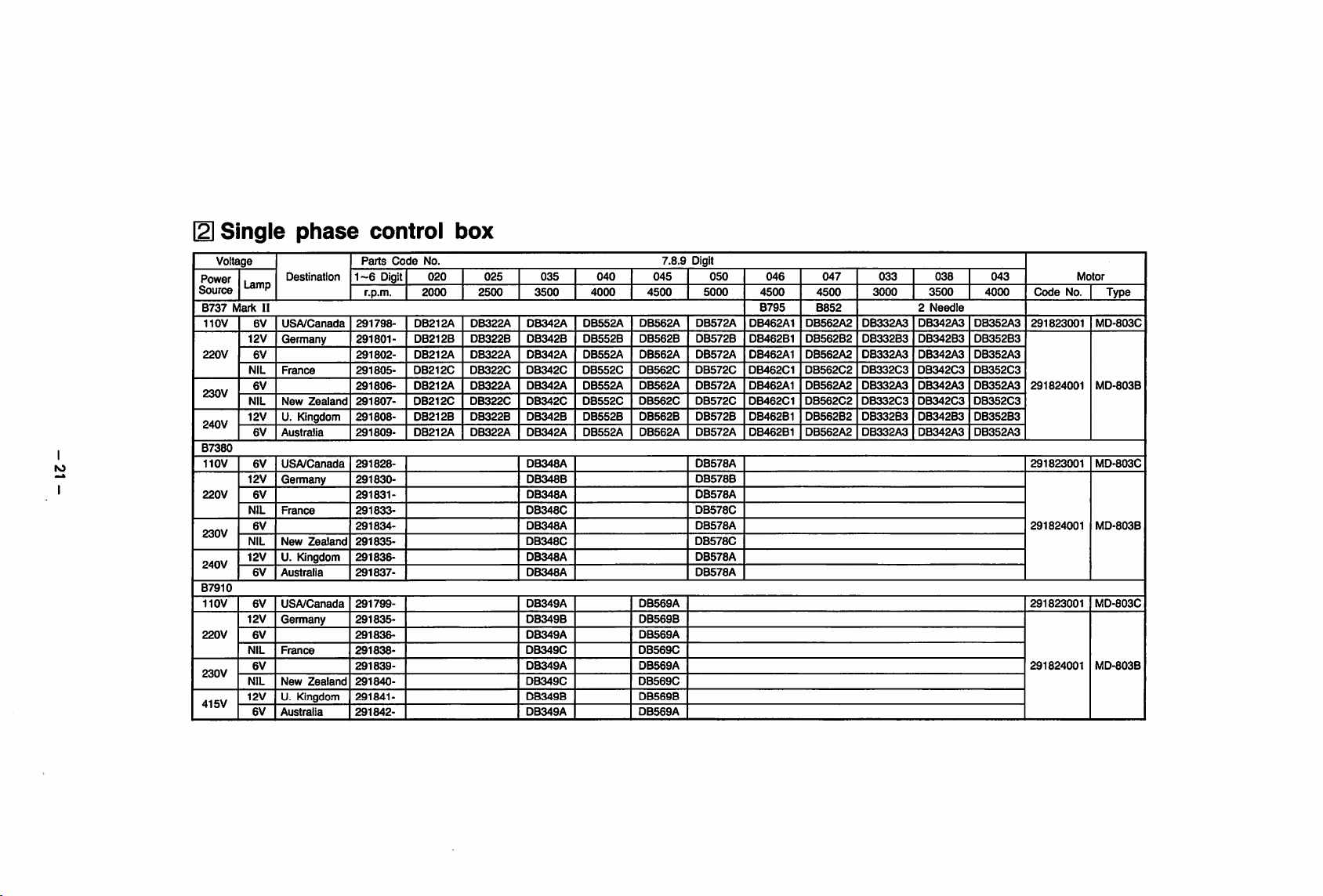
Single
Voltage
Power
Lamp
Source
B737
Mark
110V
12V
220V
NIL
230V
NIL
12V
240V
B7380
lO
I
110V
220V
230V
240V
B7910
110V
220V
230V
415V
12V
NIL
NIL
12V
12V
NIL
NIL
12V
II
6V
6V
6V
6V
6V
6V
6V
6V
6V
6V
6V
6V
phase
Destination
USA/Canada
Germany
France
New
Zealand
U. Kingdom
Australia
USA/Canada
Germany
France
New
Zealand
U. Kingdom
Australia
USA/Canada
Germany
France
New
Zealand
U. Kingdom
Austraiia
control
Parts
Code
1-6
Digit
r.p.m.
291798-
291801291802-
291805291806-
291807-
291808-
291809-
291828291830291831291833-
291834-
291835-
291838-
291837-
291799-
291835-
291836-
291838291839291840-
291841-
291842-
box
No.
020
2000 2500
DB212A
DB212B
DB212A
DB212C
DB212A
DB212C
DB212B
DB212A
025
DB322A
DB322B
DB322A
DB322C
DB322A
DB322C
DB322B DB342B
DB322A DB342A
035
3500
DB342A
DB342B
DB342A
0B342C
DB342A DB552A
DB342C
DB348A
DB348B
DB348A
DB348C
DB348A
DB348G
DB348A
DB348A
DB349A
DB349B
DB349A
DB349C
DB349A
DB349C
DB349B
DB349A
040
4000
DB552A DB562A
DB552B
DB552A
DB552C
DB552G DB562G
DB552B
DB552A DB562A
045 050 046 047
4500
DB562B
DB562A
DB562G
DB562A
DB562B
DB569A
DB569B
DB569A
DB569G
DB569A
DB569G
DB569B
DB569A
7.8.9 Digit
DB572A
DB572B
DB572A
DB572G
DB572A
DB572G
DB572B
DB572A
DB578A
DB578B
DB578A
DB578G
DB578A
DB578G
DB578A
DB578A
5000
4500
B795 B852
DB462A1
DB462B1
DB462A1
DB462G1
DB462A1
DB462G1
DB462B1
DB462B1
033
4500
DB562A2
DB562B2
DB562A2
DB562G2
DB562A2
DB562G2
DB562B2 DB332B3
DB562A2
3000
DB332A3
DB332B3
DB332A3 DB342A3 DB352A3
DB332G3 DB342G3
DB332A3
DB332G3 DB342G3 DB352G3
DB332A3
038
3500
2
Needle
DB342A3 DB352A3
DB342B3
DB342A3
DB342B3
DB342A3
043
4000
DB352B3
DB352G3
DB352A3
DB352B3
DB352A3
Code
291823001
291824001
291823001
291824001
291823001
291824001
No.
Motor
Type
MD-803G
MD-803B
MD-803G
MD-803B
MD-803G
MD-803B
Page 24
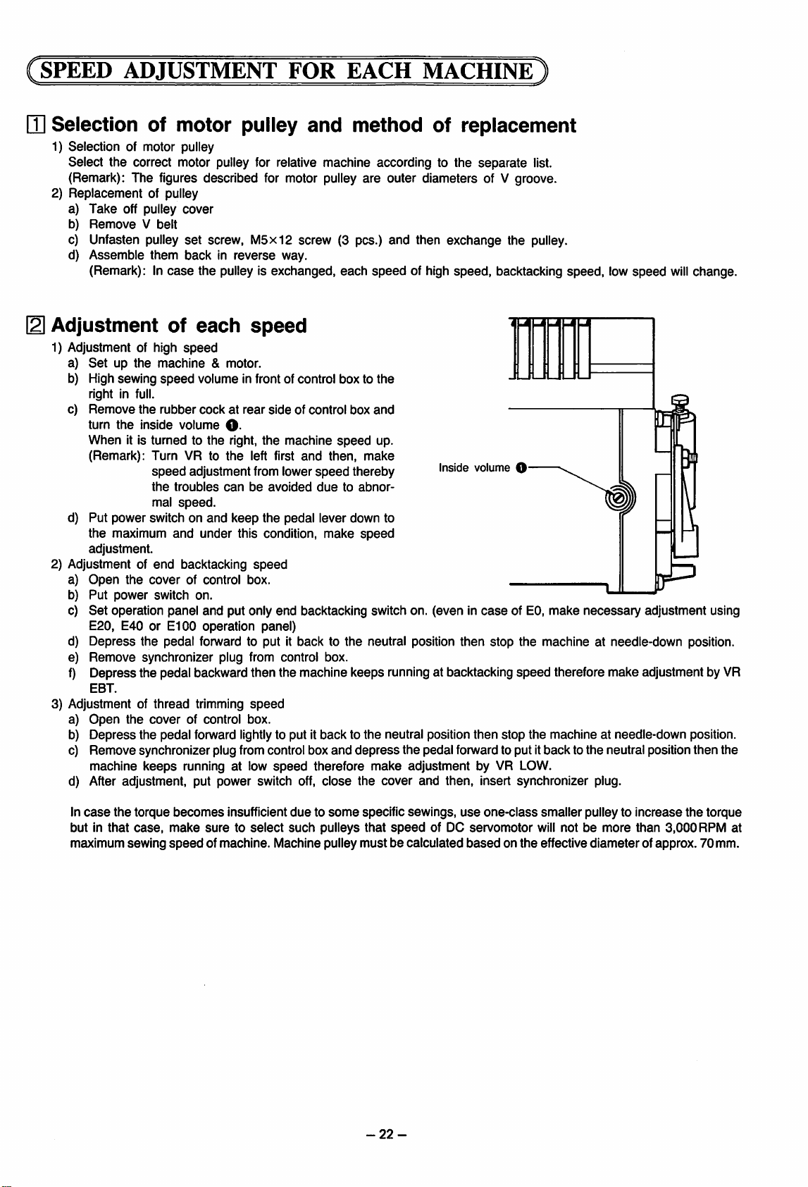
SPEED
HI
Selection of motor pulley
1) Selection of motor pulley
Select the correct motor pulley for relative machine according to the
ADJUSTMENT
(Remark): The figures described for motor pulley are outer diameters of V groove.
2)
Replacement
a)
Take
b)
Remove
c) Unfasten pulley
d) Assemble them back in reverse way.
(Remark): In
121
Adjustment of
1) Adjustment of high
a)
Setupthe
b) High sewing
right in full.
c)
Remove
turn
When
(Remark): Turn VR to
d) Put power switch on
the maximum
adjustment.
2) Adjustment of
a)
Open
b)
Put
Set
c)
E20, E40 or
Depress
d)
Remove
e)
Depress the pedal backward then the machine keeps running at backtacking
f)
EBT.
3) Adjustment of
a)
Open
Depress
b)
Remove synchronizer plug from control box
c)
machine
After adjustment, put power switch off,
d)
of pulley
off pulley
V belt
cover
set
screw,
case
the pulley is exchanged,
each
speed
machine
speed
the
rubber
the
inside volume
it is turned to
speed
the
mal
end
the
cover
power
switch
operation panel and put only end backtacking switch on. (even in
E100
the pedal forward to put it back to the neutral position then stop the machine at needle-down position.
synchronizer plug from control box.
thread
the
cover
the pedal forward lightlyto put it back to
keeps
& motor.
volume in front of control box to the
cockatrear
O-
the
right,
the
adjustmentfrom lower
troubles
speed.
and
backtacking
can
and
keep
under this condition, make
of control box.
on.
operation panel)
trimming
of control box.
running at low
M5xl2
FOR
screw (3 pcs.)
and
EACH
method of replacement
each
speed
sideofcontrol
the
machine
left first
be
speed
speed
and
avoided
the pedal lever down to
speed
box
speed
then,
speed
thereby
duetoabnor
and
depress
therefore
close
MACHINE
speed
and
up.
make
speed
separate
and
then
exchange
of high speed, backtacking speed, low
Inside volume O
list.
the pulley.
speed
0^
caseofEO,
the
neutral position then stop the machine at needle-down position.
the
pedal forward to put it back to
make
adjustment by VR LOW.
the
cover
and
then, insert synchronizer plug.
make
necessary
speed
therefore make adjustment by VR
the
adjustment using
neutral position then the
will
change.
In
case
the
torque
but in
that
case,
maximum sewing
becomes
make
speed
insufficient
suretoselect
of machine. Machine pulley
duetosome
such
pulleys
specific sewings,
that
speed
of DC servomotor will notbemore
mustbecalculated
-22-
use
one-class
basedonthe
smallerpulley to
effective
diameter
increase
than
of approx. 70 mm.
the
3,000
torque
RPM at
Page 25
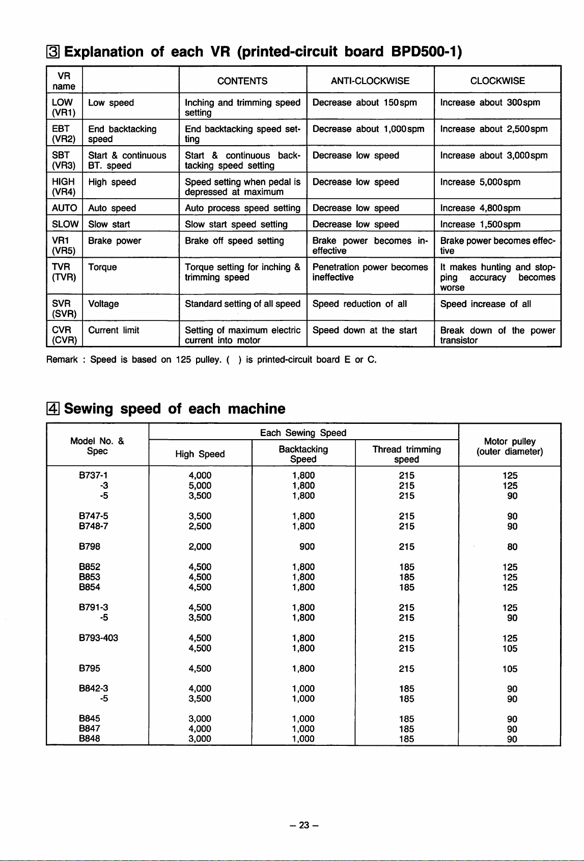
Explanation
of
each
VR
(printed-circuit
board
BPD500-1)
VR
name
LOW
(VR1)
EBT
(VR2)
SBT
(VR3)
HIGH
(VR4)
AUTO
SLOW
VR1
(VR5)
TVR
(TVR)
SVR
(SVR)
CVR
(CVR)
Remark :
Low
speed
End
backtacking
speed
Start&continuous
BT.
speed
High
speed
Auto
speed
Slow
start
Brake
power
Torque
Voltage
Current
limit
Speedisbased
CONTENTS
Inching
and
trimming
setting
End backtacking
ting
Start
&
tacking
Speed
depressed
Auto
Slow
Brake off
Torque
trimming
Standard
continuous
speed
setting when pedal Is
at maximum
process
start
speed
speed
speed
setting for Inching &
speed
setting of all
Setting of maximum electric
on
current
125
Into
motor
pulley. ( ) Is prlnted-clrcult board E or C.
speed
setting
setting
setting
speed
set
back
setting
speed
ANTI-CLOCKWISE
Decrease
about
Decrease
Decrease
Decrease
Decrease
Decrease
Brake
effective
power
Penetration
Ineffective
Speed
Speed
reduction of all
down at
about
low
low
low
low
power
150spm
I.OOOspm
speed
speed
speed
speed
becomes
becomes
the
start
In
CLOCKWISE
Increase
Increase
Increase
Increase
Increase
Increase
at>out
about
about
5,000spm
4,800spm
1,500spm
Brake power
tive
It
makes
ping
accuracy
worse
Speed
transistor
Break
Increase
downofthe
becomes
hunting
300spm
2,500spm
3,000spm
effec
and
stop
becomes
of all
power
Sewing
Model
No.
Spec
B737-1
-3
-5
B747-5
B748-7
B798
B852
B853
B854
B791-3
-5
B793-403
B795
B842-3
-5
speed
&
of
High
each
Speed
4,000
5,000
3,500
3,500
2,500
2,000
4,500
4,500
4,500
4,500
3,500
4,500
4,500
4,500
4,000
3,500
machine
Each
Sewing
Speed
Backtacking
Speed
1,800
1,800
1,800
1,800
1,800
900
1,800
1,800
1,800
1,800
1,800
1,800
1,800
1,800
1,000
1,000
Thread
trimming
speed
215
215
215
215
215
215
185 125
185
185
215
215
215
215
215
185
185
Motor pulley
(outer
diameter)
125
125
90
90
90
80
125
125
125
90
125
105
105
90
90
B845
B847
B848
3,000
4,000
3,000
1,000
1,000
1,000
-23-
185
185
185
90
90
90
Page 26

NOTES
(1)
Be sure,
Be careful to not use a single-phase powersupply. Even ifsingle-phase is used, there may be no abnormal condition.
however, that quick repeated starting and stopping
(The fuse interior
(2) The power supply voltage should be
(3)
Securely connect each connector. The
(4)Ifsingle-phase 110V is used,
For that reason, indoor
(5) For cold regions,
Inparticular, needle
(6)
Needle
wiped
(7)
Avoid
use near anyequipment, such as a
will
cause operational errors and/or damage to the D printed-circuit board (fuse
(8) For a three-phase powersupply, if130% or higher of the rated voltage is applied,the fuse
black), thus protecting the control circuitry.
REGARDING
for
use of a three-phase
will
care
(lower)
(lower)
stop
willbeabnormal
clean.
DC
power
not become black.)
±10%
all
functions
wiring
capacity should be 20A or higher, and the use of extension cords should be avoided.
shouldbetaken
stop
will
be abnormal ifmoisture condensationoccurs on the reflector plate of the synchronizer.
ifthere is
MOTOR
supply,
6-pin
will
to avoid moisture condensation.
high-frequency
to check the
will
cause
of the rating.
connector
stopifthere is even a
oil
orgrease onthe
from
welder,
INSTALLAtTo^
connection
the fuse to
the
motor
reflector
etc.,thatemits
of the
power
plug.
fail.
is, in
particular,
momentary
plateofthe synchronizer, so itshouldbe
drop of the voltage to 75% or
high-pitched
failure).
very
important.
noise,because such equipment
will
melt (fuse interior becomes
Note,
below.
carefully
-24-
Page 27
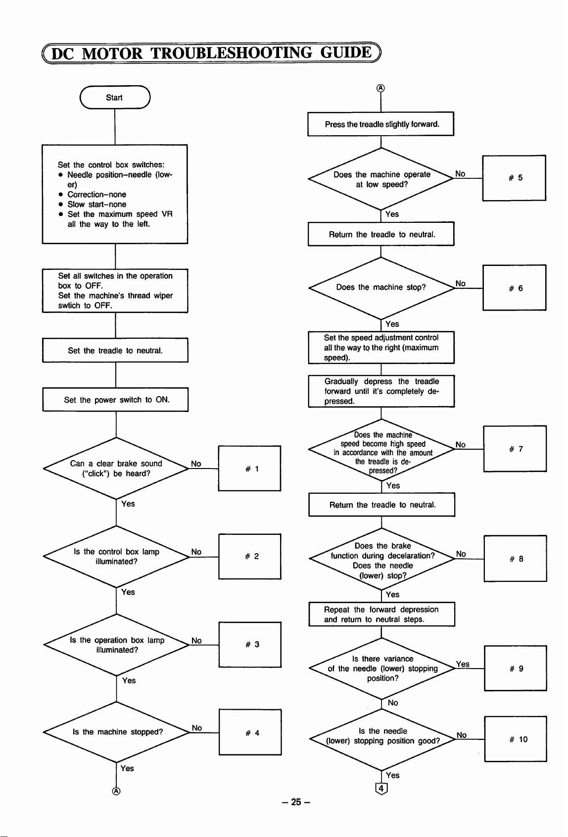
(DC
MOTOR TROUBLESHOOTING GUIDE
CjEZD
Set
the
control
• Needle
er)
•
Correction-none
•
Slow
start-none
•
Set
the
all the way to the left.
Set
all
switchesinthe
boxtoOFF.
Set
the
swtichtoOFF.
Set
the
box
position-needle
maximum
machine's
thread
treadletoneutral.
switches:
speed
operation
(low
VR
wiper
Press
Does
Return
Does
Set
the
all
the
speed)
the
treadle
the
machine
at low
the
treadletoneutral
the
speed
way to
the
slightly forward
operate
speed?
machine
stop?
adjustment
right (maximum
control
Set
the
Canaclear
power
switchtoON.
brake
sound
("click")beheard?
Is
the
control box
illuminated?
lamp
Is the operation box lamp
illuminated?
Gradually
depress
the
treadle
forward until it's completely
pressed
Does
the
machine
speed become high speed
in
accordance
the
treadleisde
with
the
amount
pressed?
Return
the
treadletoneutral
Does
the
the
forward
there
brake
decelaration?
needle
stop?
depression
steps
vanance
(lower)
stopping
function during
Does
(lower)
Repeat
the
and
return to neutral
Is
of
the
needle
position?
de
Is
the
Is
the
machine
stopped?
needle
(lower) stopping position
-25-
good?
Page 28
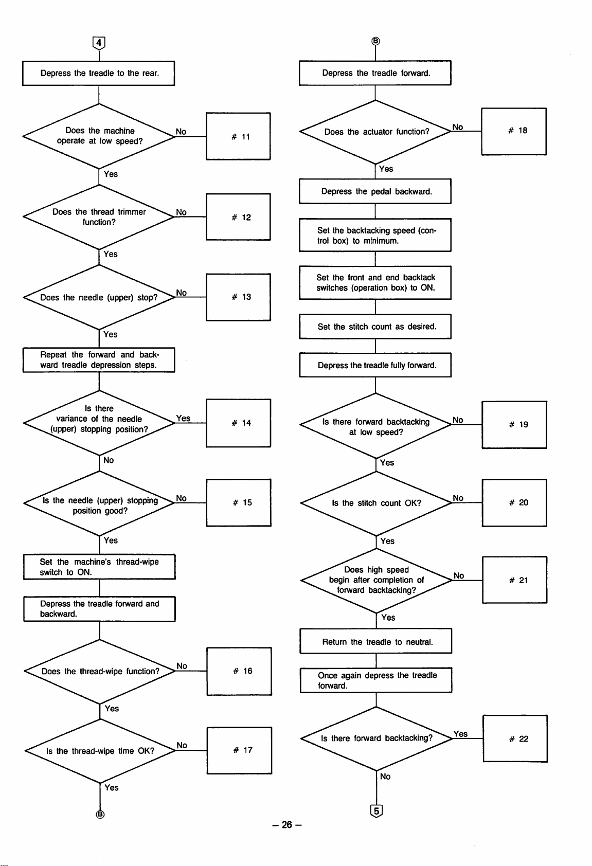
Depress
operate
the
Does
treadletothe
the
machine
at low
speed?
rear
Depress
Does
the
the
actuator
treadle
fonivard
function?
Does
the
thread
tnmmer
(upper)
Yes
fonvard
depression
there
needle
Does
the
Repeat
ward
treadle
varianceofthe
function?
needle
the
Is
(upper) stopping position?
and
stop?
back
steps.
Depress
Set
the
pedal backward
the backtacking
speed
(con
trol box) to minimum.
Set
the
front
and
end
backtack
switches (operation box) to ON.
Set
the
stitch
countasdesired
Depress
the
treadle
fully forward.
Is
there
forward backtacking
at low
speed?
Is the
needle
position
Set
the
switchtoON
Depress
backward
Does
machine's
the
the
Is
the
thread-wipe time OK?
(upper)
good?
treadle
thread-wipe
stopping^No
thread-wipe
fonivard
and
function?
Is
the
stitch
count
Does
high
speed
begin after completion of
forward backtacking?
Return
the
treadle
Once
again
depress
forward.
Is
there
forward backtacking?
OK?
to
neutral
the treadle
-26-
Page 29
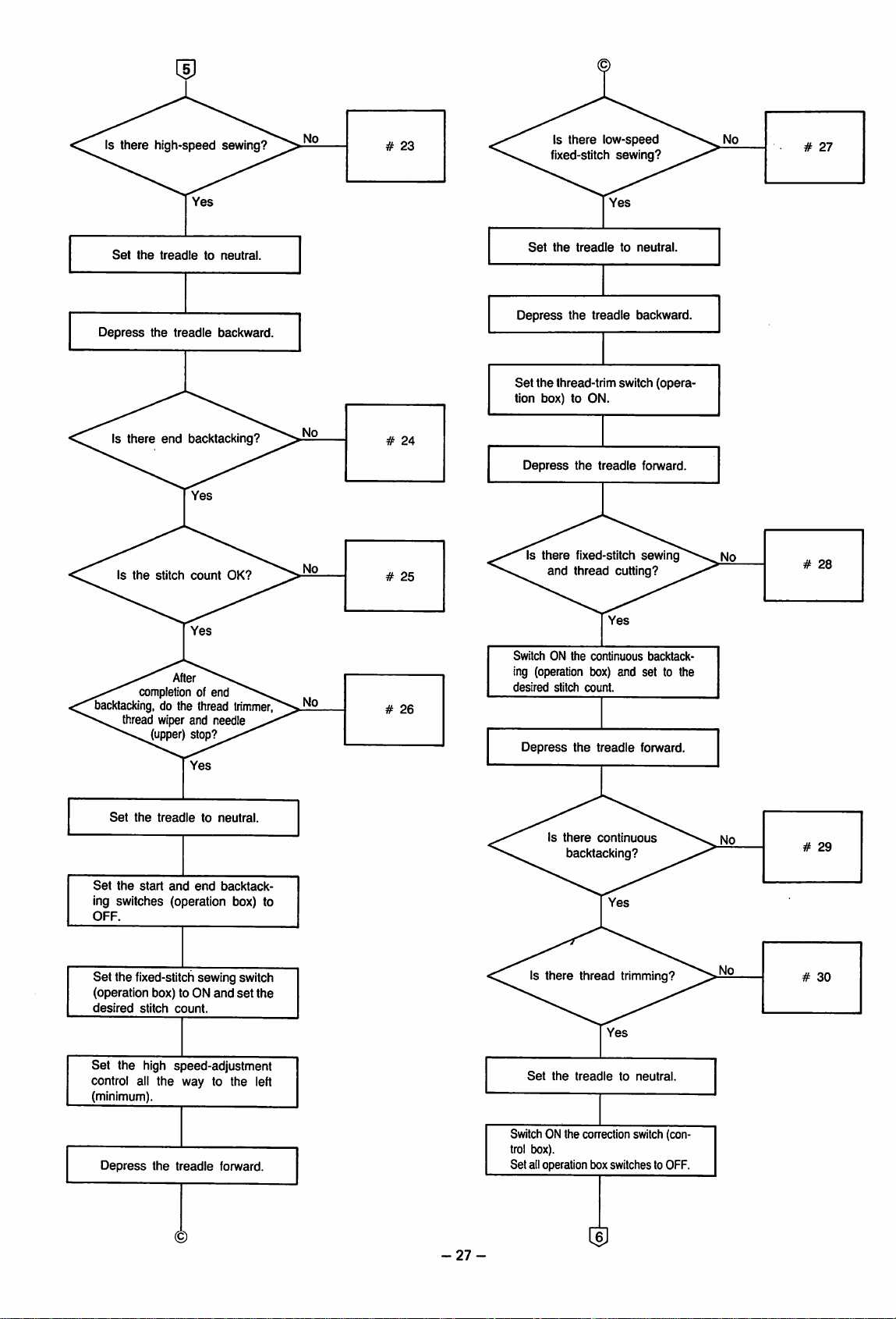
Is there high-speed sewing?
Set
the
treac
Jletoneutral.
Set
Is
there
fixed-stitch
the
treadleto
low-speed
sewing?
neutral.
Depress
Is
Is
there
the
the
stitch
tr(
end
After
completion of end
backtacking,
do the thread
thread wiper and needle
(upper) stop?
^adle
backward.
backtacking?
count
OK?
trimmer
Depress
Set
the treadle backward.
the
thread-trim switch
tion box) to ON.
Depress
SwitchONthe
Is
there
and
the
fixed-stitch
thread
co
ing (operation bo
desired
stitch
cou
Depress
the
(opera
t
readle
forward.
sewing
cutting?
ntinuous
backtack-
x) and set to the
nt.
t
readle
forward.
No
Set
the
treac
tietoneutral.
Set
the
start
and
end
backtack
ing switches (operation box) to
OFF.
Set
the fixed-stitchsewing switch
(operation box) to ON
desired
stitch
Set
the high speed-adjustment
count.
and
set
the
control all the way to the left
(minimum).
Depress
the
tr
eadle
forward.
-27-
Is
there
backtacking?
there
Is
Set
SwitchONthe
thread trimming?
the
treac
con
trol box).
Set alloperationbe
continuous
lietoneutral.
ection switch (con-
)x
switchestoOFF.
Page 30
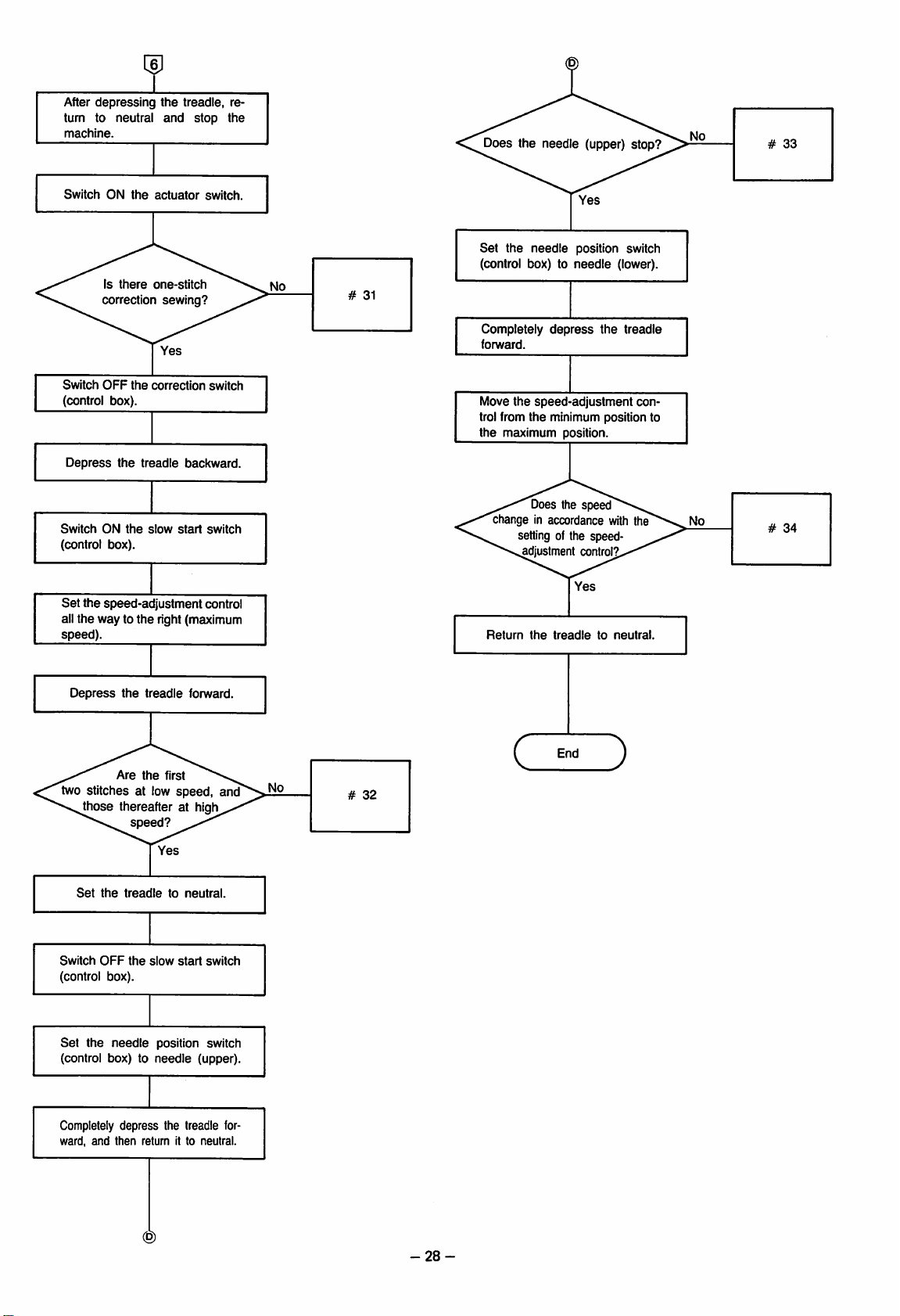
After
depressing
turn to neutral
machine.
Switch
ON
the
Is
there
correction
the
treadle, re
and
actuator
one-stitch
sewing?
stop
switch
the
Does the needle (upper) stop?
Set
the
needle
(control box) to
#
31
position switch
needle
(lower).
Switch
OFF
the
correction
switch
(control box).
Depress
Switch
ON
the
the
treadle
slow
backward.
start
switch
(control box).
Set
the speed-adjustmentcontrol
all the way to
the
right (maximum
speed).
Depress
Are
the
the
ti
eadle
forward.
first
two stitches at lowspeed, and"
^hose thereafter at higl^
speed?
No
Completely
forward.
Move
trol
from
the
depress
the
speed-
the
min
maximum p
the treadle
adjustment
mum
position to
osition.
Does the speed
change in accordance with the
setting of the speed-
adjustment control?
Yes
Return
the
treadletoneutral.
End
C
)
con-
Set
the
treat
Switch
OFF
the
(control box).
Set
the
needle
(control box) to
Completely depre
ward,
and
then
Yes
lietoneutral.
slow
start
position switch
needle
(upper).
5S
the
treadle
tumitto
re
switch
for-
neutral.
-28-
Page 31

ITEM
#1
and
#2
#3
#4
#5
#6
#7
PROBLEM
No
"click"
from
power
ON.
Control box
doesn't
No
illumination
sound
brake
when
is switched
lamp
illuminate.
of
operation box lamp.
Machine
starts
when
power is switched
ON.
Machine
operate.
Machine
reverse.
Unsuitable
speed
Machine
high
speed.
Machine
when
treadleisset
neutral.
Operation
correspond
amount
doesn't
operates
low-
operation.
operates
doesn't
doesn't
to
of
treadle
stop
depression.
CHECKING
• Is
the
PROCEDURES
connection
4-pin or 3-pin power plug
OK?
•
The
fuse
(outer
control box)
•
Fuse
fails
again
placement.
•
The
fuse
(8A
the
control box)
•
Other
than
the
•
Does
the
operation
function correctly? (YES)
•
Other
than
the
•
Does
the
control box
flash?
•Isthereamotor
•
Other
than
the
in
at
to
•
Uneven
dle
• Initial
operation at
maximum.
operation
fast (no low-speed range).
has
failed.
fuse
has
above.
above.
above.
speed
of
side
(YES)
after
failed.
noise?
the
of
re
inside
box
(NO)
lamp
(YES)
(YES)
trea
PROBABLE
Power
connected.
Fuse
Malfunctionof8A
plug is incorrectly
has
CAUSE
failed.
control printed-circuit board.
Malfunction
of
the
printed-circuit board.
Bulb
failure-no
problem.
Malfunction of
box.
Malfunction
printed-circuit
Malfunction
the
of
board.
of
the
the
printed-circuit board.
Malfunction of
circuit
board.
(single
phase
the
110
er)
Large
torque
Malfunction
printed-circuit
Malfunction
Large
torque
Malfunction
Malfunction
Malfunction
Malfunction
Synchronizer
position is not
Synchronizer
(head).
of
control
board
of
treadle
(head).
of
treadle
of
treadle
of
treadle
of
treadle
installation
good.
malfunction.
Control printed-circuit board
malfunction.
is
Malfunction
Malfunction
Malfunction
of
of
of
treadle
control
treadle
fuse,
the
control
functional
operation
control
control
D printed-
V or high
unit.
unit.
unit.
unit.
unit.
unit.
box.
unit.
REMEDY
Connect
the
power
rectly.
Replace
Replace
trol
Replace
box.
Replace
Replace
Replace
Replace
Replace
motor.
Reduce
Replace
Replace
Reduce
Replace
Replace
Replace
box.
the
fuse.
the
motor
the
fuse
the
control box.
the
operation box.
the
control box.
the
control box.
the
the
torque.
the
control box.
the
control box.
the
torque.
the
control box.
the
control box.
the
control box.
Adjust VR LOW
Replace
Position
Replace
Replace
Replace
Replace
Replace
the
control box.
adjustment:
the
synchronizer.
the
control box.
the
control box.
the
control box.
the
control box.
plug
cor
and
con
and
control
control box
and
TVR.
0.5mm
-29-
Page 32

ITEM
#8
#9
#10
#11
#12
#13
PROBLEM
Needle
doesn't
(lower)
stop.
Needle (lower)
at
various
Poor
dle
After
places.
position of
stop.
treadle
machine won't
ate
at low
speed.
Thread
doesn't
Needle
doesn't
trimmer
function.
(upper)
stop.
stops
nee
return,
oper
CHECKING
• Is
the
PROCEDURES
synchronizer
OK?
(NO)
(YES)
• Is
the
V-belt
loose?
(YES)
• Is
there
oil,
grease,
scratches,
etc.onthe
chronizer's reflecting
face?
the
• Is
motor's
braking
loud?
dirt
syn
sur
(YES)
noise
(YES)
(NO)
Is adjustment at synchroniz
er
possible?
(YES)
(NO)
• Is
thread
OK?
trimming
speed
(YES)
(NO)
• Is
the
pins) in
connected?
•
Does
1-pin plug (of
the
the
thread
the
control box
(NO)
trimmer
solenoid switch ON?(YES)
(NO)
• Switch
OFF
measure
the
thread
noid.
Is
there7ohms
and
© of
the
the
the
power
resistance
trimmer
between
12-pin?
and
sole
(NO)
•
Does
the
8A
fuse
(at
topofthe
circuit board)
mal?
• Is
the
OK?
control printed-
appear
speed
at low
nor
(NO)
speed
(NO)
• Is the synchronizer OK?
(NO)
(YES)
PROBABLE
Synchronizer
installation
position is not good.
Synchronizer
malfunction.
Control printed-circuit board
malfunction.
Insufficient
V-belt
Malfunction of
nizer.
Reduced motor braking
force.
Malfunction of
nizer.
Malfunction
of
printed-circuit board.
Poor position of needle (low
er) stop.
Reduced motor braking
force.
Low
speedistoo
Malfunction
printed-circuit
12
Improper
connectionofthe
1-pin plug.
Malfunction
thread
Malfunction
related
trimming.
printed-circuit board.
of
Malfunction
trimmer
of
solenoid.
O
8A
fuse
the
Speed
fast.
failure.
at low
Improper installation of
synchronizer.
Malfunction
of
printed-circuit board.
CAUSE
the
the
the
of
board.
of
the
speed
the
tension.
synchro
synchro
control
fast.
control
to
head
control
thread
is too
control
Position
Replace
Replace
Adjust
Replace
Adjust
ance.
Replace
Replace
Adjust
18—22
Replace
Adjust VR LOW
Replace
Connect
rectly.
Adjust.
Replace
Replace
solenoid.
Replace
Adjust VR LOW
the
Replace
Replace
REMEDY
adjustment;
the
synchronizer.
the
control box.
the
V-belt tension.
the
synchronizer.
the
motor
the
synchronizer.
the
control box.
needle
(lower)
mm.
the
motor.
the
control box.
the
1-pin plug cor
the
control
the
thread
the
8A fuse.
the
synchronizer.
the
control box.
brake
and
and
0.5
mm
clear
stop
by
TVR.
box.
trimmer
TVR.
-30-
Page 33

ITEM
#14
#15
#16
#17
#18
#19
PROBLEM
Needle
(upper)
stops
at various places.
The
stop
needle
position of
(upper) is
the
not good.
Thread
function.
Thread
tion
function.
backtack.
timeistoo
Reverser
(when
pressed
is
switched
Does
wiper
doesn't
wiper
opera
short.
doesn't
treadieisde
and
actuator
ON)
not
forward
CHECKING
• Is
the
• Is
there
scratches,
chronizer's
face?
PROCEDURES
V-belt
oil,
etc.onthe
reflecting
loose?
grease,
(YES)
dirt
syn
sur
(YES)
(NO)
• Are
the
speed
and
torque
at low
speed
OK? (NO)
(YES)
•
Can
at
the
adjustment
synchronizer?
be
made
(YES)
(NO)
• Switch OFF the power
switch
and
then
measure
the
resistanceofthe
wiper
• Is
there5ohms
and
O of
solenoid.
the
thread
between
12-pin?
(NO)
(YES)
•
Other
than
above.
•
Can
the
reverser be
atedbythe
reverse
oper
lever?
(NO)
• Switch OFF the power
switch
and
then
measure
of
the
between
• Is
the
verse
resistance
there
solenoid.
7ohms
and 0 of the 12-pin?
•
Measure
the
Is
actuator.
there
the
Oohms
(YES)
resistance
between
and 0 of the 12-pin with
the
actuator
and
00
actuator
• Is itOKwhen
stitch count is
you try
ohms
switch
again?
switch
with
OFF?
the
backtack
changed
ON,
the
(NO)
(YES)
and
(YES)
(NO)
PROBABLE
Insufficient
V-belt
Malfunction of
nizer.
Malfunction
of
printed-circuit board.
Speed
slow.
at low
Operational malfunction re
lated
to
head
ming.
Improper needle (upper)
stop
position.
Reduction
force.
of
O
Malfunction
of
wiper solenoid.
Improper
thread
Malfunction
printed-circuit
installation of
wiper solenoid.
of
board.
Improper installation of the
thread
wiper solenoid.
Operational malfunction re
latedtohead
Malfunction
solenoid.
re
of
0
of
Malfunctionofthe
O
Malfunction
printed-circuit
of
board.
Malfunction of the operation
box.
Malfunction
printed-circuit
of
board.
CAUSE
tension.
the
synchro
the
speed
thread
motor
the
the
reverse.
the
actuator.
the
the
control
is too
trim
brake
thread
control
reverse
control
control
REMEDY
Adjust the V-belt tension.
the
Replace
Replace
Adjust
TVR.
Adjust.
Adjust
stop
Replace
Replace
solenoid.
Adjust
Replace
Adjust
the
the
the
VR LOW
the
position by
the
the
the
installation.
the
the
installation.
Adjust.
Replace
noid.
Replace
Replace
Replace
Replace
the
the
the
the
the
synchronizer.
control box.
and
needle
(upper)
10~12mm.
motor.
thread
wiper
control box.
reverse
sole
actuator.
control box.
operation box.
control box.
-31
-
Page 34

ITEM
#20
#21
#22
#23
#24
PROBLEM
Does
backtack
number
not
of
(Note
stitch pitch
Won't
operate
speed
after
backtacking.
Forward
after
treadleisset
neutral.
Won't
sew
speed
after
backtacking.
Won't
reverse
tack.
fonward
the
stitches.
that
at high
forward
backtacks
at high
forward
back
CHECKING
• Is itOKwhen
set
c
are
is forward or
to
Same
stitch count is
you try
again?
mustbetaken
as
#19.
PROCEDURES
the
backtack
changed
(YES)
(NO)
because
reverse.)
PROBABLE
CAUSE
Malfunction of the operation
and
box.
Malfunction
of
the
printed-circuit board,
the
re is a dirference in stitch lengt
Malfunction
printed-circuit
Malfunction
of
board.
of
the
the
printed-circuit board.
Malfunction
of
the
printed-circuit board.
Same
as
#19.
control
control
control
control
REMEDY
Replace
Replace
h
dependingonwhether
Replace
Replace
Replace
Same
the
the
the
the
the
as
operation
control
control box.
control box.
control box.
#19.
box.
box.
the
#25
#26
#27
#28
#29
#30
#31
#31
Won't
forward
tack
set
stitch
Needle
thread
thread
stop
(upper),
trimmer
wiper won't
after
backtacking.
Won't
fixed-stitch
sew
at low
Won't
thread
after
fixed-stitch
ing.
Won't
thread
after
continuous
backtacking.
Won't
thread
after
continuous
backtacking.
Won't
1-stitch
tion
sew.
Won't
slow
Needle
stop
Speed
accordance
setting of
(upper) won't
(control box).
is not in
the
adjustment
back
count.
and
reverse
speed.
trim
sew
trim
trim
correc
start.
with
speed-
control.
the
Same
as
#20.
•Isit
OK
when
stitch count is
you try
•IsitOKwhen
stitch
you try
again?
countischanged
again?
the
changed
the
backtack
fixed-
and
(YES)
(NO)
and
(YES)
(NO)
Same
as
#20.
Malfunction
printed-circuit
Malfunction of
box.
Malfunction
of
board.
the
of
the
control
operation
the
control
printed-circuit board.
Malfunction of the operation
box.
Malfunction of
box.
Malfunction
printed-circuit
Mulfunction of
box.
Malfunction
printed-circuit
Malfunction
printed-circuit
the
of
board.
the
of
board.
of
board.
operation
the
control
operation
the
control
the
control
Same
Replace
Replace
Replace
circuit
Replace
Replace
circuit
Replace
Replace
circuit
Replace
Replace
Replace
as
#20.
the
operation
the
operation
the
control printed-
board.
the
operation
the
control printed-
board.
the
operation box.
the
control printed-
board.
the
operation box.
the
control box.
the
control box.
box.
box.
box.
-32-
Page 35

ITEM
#32
PROBLEM
Machine
ing sewing.
stops
CHECKING
dur
• Is the power lamp
flashing? (YES)
PROCEDURES
(NO)
PROBABLE
Head
torque
Safety
circuit
because
rication of
Malfunction
unit.
Malfunction
is large.
of
insufficient
the
of
of
CAUSE
has
rotary hook.
the
the
printed-circuit board.
Malfunction
printed-circuit
of
board.
the
operated
lub
treadle
control
control
Lubricate
Replace
Replace
Replace
REMEDY
the
rotary hook.
the
control box.
the
contorl box.
the
contorl box.
-33-
Page 36

(control
box
troubleshooting
guide
outline
PROBLEM
1. Motor won't
operate.
Lamp won't illuminate with power
ON.
(Fuse
the
failed.)
2. Motor won't operate. B
Lamp illuminates with power ON.
3. Machine
rotation wih
4. With
Thread
Reverse
Brake
All
5. With
high
6. With
imum,
power
tirmmer
remains
continue.
treadle
speed;
treadle
abnormal
power
ON:
continues.
ON.
forward,
won't
depressed
high-speed
high-speed
ON.
continues.
abnormal
stop.
changes.
(High-speed rotational irregularity)
7. During
speed,
great
stop
speed
reduction from high
brake
doesn't
deviation of
position.
function, or
needle
A
to
max
rotation
(lower)
(1)
Fuse
CHECK
is replaced
METHOD
and
fails again.
(2) Operation OK after fuse replace
ment.
(1) LED
(2) Motor
(3)
flashes
tack.
Others
during fon/vard
roarsorhums.
back-
REPLACEMENT
PART
D printed-circuit board PTR, D (If PTR
broken
motor frame
assembly)
then
Due to operation of overvoltage protec
tion
circuit;noabnormal
Treadle
C1,
CPU.
HIC1,
HIC4, HIC5,
printed-circuit
HIC5
brake
HIC2,
PTR
HIC6
HIC6
D printed-circuit
phase
110V)
Thread
Reverse
Brake
CPU
HIC2
HIC6
Poor
board.
HIC6
HIC3
trimmer
PTR5
PTR1
solderingoftreadle
1
PTR2
board
condition.
board
tantalum
PTR (single-
printed-circuit
-34-
Page 37

C
CONTROL
BOX
TROUBLESHOOTING
GUIDE
DETAILSl
(1) For other than
(2) Do not
(3) About
use
the
the
control box, it is particularly Important to
an extension cord for
power supply of
the
the
motor's 6-pin cord. Extension cords
p.c.b. BPD500-1.
use
products of confirmed good quality.
can
be used, however, for other cords.
• The p.c.b. BPD500-1 is divided into three power-supply groups (part A, part B and part C).
• Although part A (0Vgroup) is insulated at
circuits (primary
side
voltage)
duetothe
• For that reason, it is extremely important, before checking part B
suretofirst
Also disconnect
disconnect
the
CN5
motor
and
connector
/
j oil
•Jest
M
CSIu
DM M
V*
•ST YA
DM W
vv
DS7
M
n|
CN4.
the
transformer, part B
CN5
and
(which is
i -
II
among
%
(O50V
CN4 connections,
(O50V
the external connectors).
CU
I 4 CM
5
a-r
group)
and
part C
andsoare
group) and part C
•
«
BP0500-I
<•
* - s >
§ BCMX$
is
(^^$_
(O100V
dangerous.
(O100V
<2,
H
on sn wsS|
group)
are
high-voltage
group), to be absolutely
\
A
cw*
o*Ol
•rt>o«
•
8*(S)
OV
sr
ViA
CSS
KlOl
uiu
xi
PartCO100V
Tir
tf
00
•MS
XX
group
HICO
m
5 1
,
§*8
.c.
»•«'
001 ^
Dios
Part B
O50V
group
t W
VA
Part
O '
A OV
Mri I I
am*
group
DMi
11
I
11
n
-35-
Page 38

Ul Main
Fuse
Motor
starts
switch
ON.
flow-chart
failure.
when power
START
Disconnect (among the external connectors) the power-supply connector, the
motor connector,
trimmer connector,
the
brake
and
connector,
the
three
the
presser
stand-operation
foot connector, the thread
connectors.
Among the internal connectors, disconnect the CN5 from he D printed-circuit
board.
Connector
related (p.39)
Machine
ate.
doesn't
oper
PTR,D:OK
#1 (p.39)
Fuse
Fuse
#2
failure
(p.39)
replacement
(operation of overvoltage
protection circuit)
1. Connect only the power-supply connector (which is one of the extemal
connectors).
2. Among the internal connectors, disconnect the CN5 from he D printed-
circuit
boardanthe
Note:
All
other
3. Turn the VR for high
CN8
internal
from
connectors
speed
Power
ON
LED1illumination
#3
(p.39)
CN8 voltage: OK
#4
(p.42)
the
transformer.
mustbeconnected.
all the way to the right. (Note)
Transformer replacement
Refer to the section concerning disconnection
and
removalofprinted-circuit
then disconnect and remove the printed-circuit
boards and
replace
the
transformer.
Printed-circuit
board/removal
(p.40)
Connector
related (p.39)
Connector
related (p.29)
#3-1
(p.41)
boards (p.40):
Switch OFF the power, connect CN8,
and then the power switch ON.
Set
the
treadle
lever
for forward
LED1 flashing.
#5
(p.39)
Set
the
treadle
levertoneutral
Power
OFF
Connector
related (p.39)
depression.
#5-1
Treadle
related
#7-1
p.43)
2 (p.51)
(p.44)
Note:
Be absolutely
disconnection
board
sure
to disconnect CN5. If
is forgotten,
willbedamaged.
the
printed-circuit
A
Page 39

Wiper operation with
power ON.
w
Caution (p.47)
1.
Connect
2. Three printed-circuit board switches: needle
correction switch:
3.
Turn
ail
connectors
the
high-speedVRall the way to the
except
the
OFF;
slow-start switch: OFF.
Power
ON
Motor
starts
operation
box.
position
left.
YES
switch:
lower;
Connector
related (p.39)
Retum
to
"START"
(p.36)
Thread
tion with
Reverser
power
Brake
ON.
Motor
trimmer
power
operation with
ON.
ON with
roarsorhums
opera
ON.
power
dur
ing forward backtack.
LED flashing during for
ward
backtack.
Wiper
Thread
operates.
Reverse
Brake
Machine
operates
#100
trimmer
#101
operates
#102
sound
#103
pulley is light
#103
YES
YES
YES
#100-1
#101-1
#102-1
#103-1
Abnormal high
forward
Pedal
one-stitch
difficult.
Sometimes
speed
depression.
sewing
not
thread
trimming.
Deviation of
er)
and
needle
needle
(low
(upper)
stopping.
speed
High
low
OK, but no
speed.
Pedal low-speed range
is
narrow.
Treadle
at
lever to forward
flashes
Operation
depression
Retum
"START"
(p.36)
#104-1
to
(p.50)
Retum
Operation
to
"START"
(p.36)
Have
#3-#7
adjustments
been
made?
D printed-circuit
board
check
e
(p.42)
Tum high-speed VR all the way to the right.
#106-1
(p.50)
A
-37-
Page 40

Starting rotation slow
#107-1
YES
speed.
—•
NO
Treadle
(p.51)
related
(P37)
2
High-speed rotational
irregularity.
Speed
reduction brake
doesn't
function.
Continuous
low
speed.
rotation
Good
Rotation
to
slow-speed
#107-1
corresponds^
treadle
stroke.
^
YES
depression.
NO
NO
-iTYES
High-speed
rotationisstable.
^
#107-4^-.--
YES
Pedal
neutral
Speed-reduction
functions.
at
Machine
brake
#108
YES
stops.
#109
YES
NO
NO
NO
#108-1
(p.53)
#109-1
(p.54)
Needle
stop.
(upper)
doesn't
Stop
position: OK
#110
♦4
YES
Backward treadle depression.
Machine
Thread
#111
trimmer
operates.
YES
functions.
#112
YES
Stops.
YES
Wiper functions.
#113
YES
NO
NO
NO
NO
NO
#110-1
(p.54)
#111-1
(p.55)
#112-1
(p.56)
#113-1
(p.56)
END
-38-
Page 41

HI
Connector
Fuse
failure (#2,
LED 1 illumination
LED 1 flashing
(#5)
related
#3-7)
(#3)
Thread
Presser
trimmer
foot
Brake
connector
connector
connector
PTR,
D: OK
#1
PTR
High-speed
installation
Brown
screw
VR
wire
8A
fuse
Operation
Fuses
connector
(#2)
(#3-7)
Motor
connector
Power-supply
connector
Purple
wire
PTR
andDcheck
1.
2.
Remove
Set
the
the tester to the X 1Q range (Oohm adjustment).
3. PTR continuity
Between PTR installation screw
Should
not
4. D continuity
Between
Should
Note:
If
the PTR is damaged, replace the frame assembly of the motor used as a set
weak
and
not
all rotation
methods
three
treadle
unit installation
screws
O-
test
and
purple wire
be
Oohms
in
both
directions.
test
D
case
and
brown
wire
be
Oohms
in
becomes
both
directions
higher.)
Treadle
with
the controlbox. (The motortorque becomes
unit
Installation
screw
O
-39-
Page 42

Printed-circuit
board
removal
Nylon
band
Remove
the
three
treadle
Transformer
installation
screvt^s.
Disconnect the transformer connector from the nylon band. Disconnect the transformer connector.
connector
®
r~in
n
Printed-circuit
installation
Printed-circuit
installation nylon
(1)
Disconnect
(2)
Remove
(3) Remove the three printed-circuit board installation nylon pins.
CN2, CN3, CN5, CN6, CN7,
the
two printed-circuit
Nylon pin
board
and
installation
screws
CN8.
screws.
r
Press
from
both
sides.
board
board
(two)
pins
(three)
Remove
Transformer
the four printed-circuit board installation screws.
connector
Printed-circuit
installation
ml
board
screws
(four)
E]
o ^
®
Remove
UtibtitiUUtd
©
o ®
-D printed-circuit board
installation
C
© ®
the
four D printed-circuit
^
11^1)
i a 0
Pull
the
printed-circuit
©
screws
board
—en
a
r
board
(four)
JJ
installation
o (
panel.
screws.
@
CO
1
®
Printed-circuit
D printed-circuit board—
(1)
Remove
(2) Remove the nylon pin (same as @-(3)).
board
panel
V
the
two D printed-circuit
-Remove the hexagonal screws.
D printed-circuit
installation
screws
board
(two)
©
'
(j
•Nylon
pin
board
installation
screws.
-40-
Page 43

LED
illumination
More
than
1
#3
#3-3
CPU pin 28 (Reset)
+4.5
Less
ttian
5V
V
Dispose
of
printed-circuit
board.
Replace
the
CPU.
#3-4
(REG1 IN)
Check
Replace
LED
Replace
the
CPU
HIC2.
YES
1
Power
OFF
0.6
CN6 voltage: OK
#3-6
Power
s
ON
yes
failure
Transformer
vollage: OK
#3-8
(p.32
D
C20isshort
or
circuited;
replace.
Replace
REG1.
#3-1,
Replace
BD
#3-5
1
D
presented
circuit
check
(p.32)
board
O
Replace
transformer
(p.30)
the
(REG1 OUT)
presented-
circuit
check
(p.32)
board
Q
#3-6
Between
red
wires
#3
OV:
5V
related
Check
OUT:
#3-1
REG1
+5±0.5V
OUT
pin OV
OK
Check
CLK:
Refer
above.
#3-2
to figure
OK
pin
CPU
pin 28: OK
#3-3
Must
be
or higher.
+4.5V
5V
REG1
Refer
above.
#3-3
#3-2
Check
IN:
#3-4
IN
to figure
CPU-28
pin CLK
#3
OK
(LED1)
REG1
OohmsatXI
range
5V
+0.5V
OUT:
#3-5
OUT
+4.5
V or higher
or
ower
CN6 voltage: OK
OO
AC 8V or higher
between
wires
10msor
H
#3-6
red
+8V
less
-I
or higher
Transformer
Rating
(Refer to p.32.)
primary
voltage: OK
#3-8
10%
-41
-
Page 44

SI D printed-circuit
D printed-circuit board
1-110Vassembly
1-240V
assembly
board
D
printed-circuit
5"
D printed-circuit board
3-240V
3-415Vassembly
assembly
board check 0 D printed-circuit board check 0
(evil)
(Jd
'—*•
!m]cH2
o
(vclIiJi**)
CM2
^S)
printed-circuit
check
O
D printed-circuit
check
0
D
printed-circuit
board
board
board
check
O
BD 0 - 0 both directions: must not be OQ
D
printed-circuit
board
check
0
Is solder of connector lead wiring OK?
D
printed-circuit
Between
Transformer
Nylon
band
Transformer
connector
primary
orange
board
check
wires: must be
voltage:
OK
0
#3-8
0-5
D1-D6
D printed-circuit
board
check
O
D printed-circuit board
check
0
I'
D
printed-circuit
BD
D1-D6
D
printed-circuit
both
board
directions:
board
check
check
O
must
0
not
be
OQ
Is solder of connector lead wiring OK?
D
printed-circuit
Q
Between
CN8
voltage:
orange
Orange
board
check
wires: must be
OK
#4
BPD500-1 printed-circuit board
wire
Gray wire
0
0-5
Q
/ Orange
wire
(1)
Remove
the
three
treadle
unit installation
(2) Disconnect the transformer connector from
(3)
Check
the
AC
voltageofthe
transformer
Treadle
screws
screws.
the
connector.
unit
(three)
nylon band.
-42-
installation
Orange
Gray
wire
Orange
wire
AC15±3V
AC15±3V
wire-
AC30±6V
Page 45

More
flashing
than
15V
Dispose
printed-circuit
board
LED
1
#5
Less
than15V
of
Disconnect
CN3.
#5-2
Power
OFF
Replace
i " SI
MHi
*It*
ts
HIC5
2 I ^
Treadle
1 (p.41)
CN3
connection
related
+15V NG Replace
C71 or
C80
-15V
NG Replace
C72
or C81
b,
BPDSOO-
+15V
NG
Replace
-15V
REG51
NG
Replace REG52
#5-4
D51.»K"
D54"A"
CN7
voltage: OK
#5-5
Replace
the
transformer
(p.40)
10msor
+25
-25V
Replace
BD51
less
V or higher
or
lower
(P36)
#5-1,
(D51"A")
#5-4
#5-3
P51»K
#5-1,
(D54»K")
#5-5
-4
#5-3
(CN7)
#5-5
Yellow
CN7
wire
(D54"A")
Black
wire
#5
related
O50V:
Check pin
±15VOUT:
D51mA"
D54/.K"
#5-1
+15±0.5V
-15±0.5V
O50V
OK
±15V
D51-A"
D54»K"
#5-3
OUT:
OQ
-43-
Refer to
±15V
the
IN:
#5-4
figure
OK
above.
P
CN7 voltage: OK
Refer to
#5-5
the
figure above.
AC
AC
Yellow
20±4V
40±8V
wire
Page 46

CN5 pin 2: OK
^
#7
More
than15V
Dispose
printed-circuit
board.
NO
^
NO
of
±15V
OUT:
#7-1
OK
^
YES
NO
Less
than15V
Power
OFF
CP9:
OK
#7-4
NO
PH52 pin 1: OK
#7-5
|N0
(P35)
+15V:
-15V:
YES
YES
NG
Replace C110.
NG
Replace C111.
Replace
HIC4.
YES
±15V
IN:
#7-3
±15V
IN:
#7-2
+15V:
NG
Replace REG101.
-15V:
NG
Replace
Replace
HIC4
R111
PTR101.
OQ
NO
OK
YES
REG102.
NO
Replace
BD101.
#7-1,
#7-3
#7-2
#7-2
#7-1,
#7-1-#7-5
OiooV:
HIGH VR
#7
(HIGH)
#7-5
PH52-4
(D101"K")
(0101
(D104»A")/
#7-3
related
Check pin
must
•^^st
»K")
(D104mK")
OiooV
be fully to right.
CN5 pin 2: OK
#7
—£to.EC_i5
' ' "•
ttf-iu
#7
(CN5-2)
#7-4
(CP9)
±15VOUT:
#7-1
OK
SB"
-M-rtiTs
±15V
#7-2
8 til * Ml *
IN:
OK
±15V
#7-2
D101.-K"
D104//A"
OUT:
#7-3
OQ
CP9:
#7-4
OK
+17V
10msor
-17Vor
PH52
(P36)
or higher
less
lower
pin 4: OK
#7-5
Pedal
Pedal
neutral
forward
-0.7±0.2V
+
12Vorhigher
DIOImA"
+
15±0.5V
D104.rK"
-15±0.5V
Refer
upper
gure.
to
-44-
right fi
•101»A"
D104r,K"
OQ at XI
range
+
14V
-14
V or higher
or higher
-0.3V
or
lower
+0.3Vorhigher
Page 47

CP3:
#7-6
CPS:
#7-7
CP4:
#7-8
OK
YES
OK
NO
OK
NO
NO
YES
YES
Replace
Replace
Replace
HIC6.
HIC6.
HIC6.
A(P36)
#6
CPS:
OK
OsoV:
Check
pin O50V
With VR4 fully right:
Pedal
Pedal
neutral:
fully
#6
#6
OV
forward: 8.5V or higher
(CPS)
HIGH)
'I"r
00
CM
CM
PH1B
NO
(P46)
#7-8
#7-7
#7-8
YES
(LOW)
(HIGH
(CP4)
Replace HIC5.
n-i
^ f—
t "
5=8
tiss.g
I.OQ.'tZj
.aotrt'i
(CPS)
#7-9
(PH1B-6)
CM
IF
#7-6
(CP3
#7-6—#7-9
O50V:
Check
Pedal
Pedal
neutral
forward
related
pin
O50V
CP3:0K
#7-6
^ ^
V
-3+1V11500+50
v^v
J-3±1V
\
mS
HIGH VR
right.
H-6.S±0.SV
CP6:
OK
#7-7
mustbefully
-8±2V
-45-
CP4:
OK
#7-8
LOW VR: at 12:00 posi
tion
0~+0.1V
+1.0Vorhigher
PH1B-6 pin
#7-9
0~+0.1V
-H.OV
or higher
Page 48

HIC2 pin 15: OK
#7-10
CPU pin 9: OK
#7-11
CPU pin 28: OK
#7-12
Check
pin
CLK:
OK
#7-13
ICS
PS:
OK
#7-14
ICS
P4:
OK
#7-15
Replace
the
CPU
Replace
HIC2
I
Replace
the
CPU
Replace
HIC1.
Replace
CPUorHIC2
Treadle
the
related
{p.51)
Replace
HIC1
i
Replace
Replace
#7-18
#7-17
#7-16
#7-10
#7-15
#7-14
Pedai
Pedal
Pedal
Pedal
(HIC1-18)
(HiCI-11
(ZD1»K")
(HIC2-15
(ICS-4)
ICS-S
neutral
forward
neutral
forward
.
HIC2 pin 15: OK
#7-10
4.5V or higher
0.5Vor
0.5Vor
0.5Vor
lower
HIC1 pin 11:
OK
#7-17
lower
lower
CPU pin 9: OK
#7-11
4.5
V or higher
0.5Vor
lower
HIC1 pin 16:
OK
#7-18
4.5
V or higher
0.5Vor
lower
"»'.«[
j LJ:
s=t=
5
CPU pin 28: OK
#7-12
4.5
V or higher
#7-10—#7-18
OV:
'I—I.
Check
Refer
upper
gure.
Check
pin
CLK:
#7-13
to
right fi
related
pin OV
Check pin OV
#7-12
#7-11
OK
ICS
0.5Vor
0.5Vor
CPU-28)
(CPU-9)
P3:
#7-14
lower
lower
0.5Vorlower
OK
ICS
4.5
0.5Vor
#7-15
V or
mu
P4:
higher
lower
#7-13
OK
4.5
V or
ZD1
#7-16
4.0
V or higher
"K":
(PS6)
250nsec
higher
OV
OK
-46-
Page 49

Caution
/
l^jmCD^^^FCRSA:^^
DM M
•M
KT
BM M
DST M 4.
y
m
¥h
»tagf
D».
8
•>..'W*
U*
<4-
Oi ~
"8
FERSr
^^''^'i-Wrsn'
s*wir^r-s
tt
«
KIC.
OO
94
91
♦
sSS
s
CM CM
.Q;0
»«
t"
•"
--0
'I
J
11
Ml
4t
^«a
3„i
\
i
•"
M
BP0500-1
+ *
a
"
<»
Ota
•ro«o
•
"O
1
Part
B +
Part
C
Note:
Because part Band part C are connected to the high-voltage
touch
them.
circuitry
for this and subsequent tests, care must be taken not to
-47-
Page 50

Wiper
operates
#100
trimmer
Thread
operates.
#101
Check
#100-2
#100-4
Replace
the
CPU
Replace PTR5
Replace HIC2.
Replace
CPU
Replace
the
and
the
HIG2.
CPU
Check
Replace
the
CPU
Replace PTR2
Replace HIC2.
Replace
CPU
Replace
the
and
the
HIC2
CPU.
#100
OV:
#101
OV:
related
Check
Base
related
Check
pin OV
PTR
3B:
#100-1
1Vorlower
pin OV
Si
#100-2
#101-2
OK
a •
-1
(PTR2-B)
(CPU-46)
(CPU-47)
CPU pin 46: OK
#100-2
4.5
V or
higher
CPU pin 28: OK
4.5
#100-3
V or
0.5Vorlower
higher
#100-4,
#100-3,
#101-4
#101-3
(CLK)
(CPU28)
#100-4,
/f
Check
#100-4
Refertoupper
#101-4
250nsec
4.5
V or higher
pin CLK: OK
right figure.
PTR
2B:
Base
OK
#101-1
IVorlower
CPU
pin 47: OK CPU pin 28: OK
#101-2
4.5
V or
higher
-48-
4.5
#101-3
V or higher
Refer to upper right figure.
Check
pin CLK: OK
#101-4
Page 51

Reverser
operates
#102
Brake
soundisheard
#103
#103-2
(PTRI-Base)
#102-1
(PTR5-Base)
#102-2
(CPU-45)
#103-3
(CPU-48)
"^11®"*
® '
\ "•
Check
'r)"'
IN?
Replace
the
—II—I
i
h 1
CPU
"oV:
I ^ zhii' w '
1!!.
RsnMM—I
•"
Replace
Replace
Replace
CPU
Replace
I
and
I
the
the
PTR5
HIC2.
HIC2
CPU.
***
•'O*
#102-4,
(CLK)
#102-3,
(CPU-28)
Check
#103-5
#103-4
Replace
the
CPU.
IVorlower
0.5Vor
Replace
the 8Afuse
Replace
Replace
Replace
CPU
and
^
YES
Replace
#103-2
When power ON.
I ^I
#103-3
#102-4,
When
lower
If
synchronizernoconnect
#103-5
PTR1
HIC2.
the
HIC2.
the
CPU.
Approx.40ms
power
—
Approx. 40ms
1.5±0.5V
ON.
4.5V
250nsec
or higher
300
ms
P37)
#102
OV:
#103
OV:
Refer to
related
Check
Base
related
Check
pin OV
PTR
#102-1
IVorlower
pin OV
PTR
#103-2
upper
5B:
OK
IB:
OK
right figure.
CPU pin 45: OK
4.5V
CPU pin 48: OK
Refer to
CPU
#102-2
or higher
#103-3 #103-4
upper
right figure.
-49-
4.5
CPU
4.5Vorhigher
0.5Vorlower-
pin 28: OK
#102-3
V or higher
pin
28:
OK
4.5
jMnn:
Check
pin CLK: OK
#102-4
upper
Refer to
Check pin CLK; OK
Refer to upper right figure.
right figure.
#103-5
V or higher
Page 52

Operate
at high
#104
speed.
Motor 6-pin
OK
Replace
HIC6
adjustment
Replace
connector
#104-1
HIC5 &
RIGS &
Motor 6-pin
connector
repair
#104-1
Cheak
this
related
I
ID
mm
connection
©
is
correct.
#106,
#106-1
Operate
the
machine
without "hunting",
maximized.
related
make
at low
the
speed.
Hold
the
machine
TVR adjustmentsothat
#106,
(P37)
pulley
and,
torque is
#106-1
(TVR)
DM
M
KL ft « ^ 204
Wl
If
iLSiiiJ
OO
CM
zx
ajpc
N1C4
CM
-50-
CM CM
Page 53

Treadle
Phot
Int&VC
unit
chart
CP5
(VC) V
8.5-
2.0-
0.5-
4000
•1000
-215
t
SPM
I
Adjustments
FRONT
REAR
PRES
DOWN
-8
Trim
Pres.
up
itral
Nei
Shutter
231079001
0.5Vor
L
level
Pres.
down
...
Low
sp
Shutter
lower
Variable
sp.
14.5
16
Top
sp.
Adjust
the
shutter positionsothat it uniformlycontacts both Q2
Q3atneutral.
Note:
When
the
treadle is fully
be
within
the
Connector
left
related
depressed,
1/3ofQ1.
the
edge
Aof
the
shutter must
and
©
1) Connect only the power-supply connector of the external
connectors.
2) For
the
internal connectors, remove only CN5 from
the
D
printed-circuit board.
3) Making
approximately
the
the
above
adjustments
adjustments
4000spm
are
completed,
will
(125 pulley),
use
set
the
so,inthe
VR3 to
machine
condition after
set
to maximum
speed
to
speed.
-51
-
©
Page 54

4000
SPM
3000
VR1
ADJUSTMENT
4000
SPM
3000
VR2
ADJUSTMENT
<
3
>
&
"c
B
o
a
VR1
left
^
2000
1000
215
U1
to
4000
SPM
3000
2000
VR3
ADJUSTMENT
VR3
right
w ; VR1
• right
; I ;
; ^ I ^ /
16
VR3
left
mm
2000
1000
215
4000
SPM
3000
2000
VR4
ADJUSTMENT
;
VR2
' left
16
mm
VR4
right
VR4
left
1000
215
16
mm
1000
215
16
mm
Page 55

Deceleration
brake
^
#108
functions.
NO
^
VR1:
OK
#108-1
YES
CPU 26 pin: OK
^
#108-2
YES
Replace
HIC6.
Si—II—I =oS^
" stT. I
B 1
£ -
i
£
•
•
ii
•
E
»
•*
NO
Adjust VR1.
NO
^
Replace HIC3.
(P37)
iSTi
'Hgteasgl
BP0500-1
B CM
^ _It^ Bi
*=5?<2.
>_
an
"
au
•
o«
sn
#108-2
(CUP-26)
#108
related
OV:
Check
CPU pin 26: OK
pin OV
VR1:
#108-1
The
VR1 position
#108-2
OK
During high
During low
mustbewithin
speed
0.5Vorlower-
speed
0.5Vor
lower
J
M
*"
1
the
range
to
© ~
(3:00)
fUMiuum
(S)
(extreme
4.5Vor
right)
higher
4.5 V or higher
#108-1
(VR1)
-53-
Page 56

Machine
#109
stops.
NO
Stop
position: OK
#110
NO
Low-speedIsgood.
#109-1
YES
CPU pin 39: OK
^
#109-2
Replace
^
NO
HIC1.
#109-2
(CPU-33) Needle down signal
NO
Adjust VR LOW.
YES
Replace the CPU.
(P37)
Low-speed is good.
#110-1
YES
Replace
HIC3.
NO
Adjust VR LOW.
(P37)
#109-1,
(VR LOW)
#109,
#110
#110-1
related
OV: Check pin OV
II 1
.^Ir
Xi
[
b
. rV-^'.ig^»'\
8<2»
y5r
ov
^
^:[][][]1
XX
^Gy
fp'
Low-speed is good.
#109-1
VR LOW:
215±10spm
pin 39: OK
#109-2
Needle
(lower) position:
Other
than
position: 4.5V or higher
0.5Vor
needle
lower
(lower)
Low-speed is
VR LOW:
-54-
#110-1
good.
215±10spm
CPU
Page 57

Machine
operates.
#111
Replace
the
#111-4
#111-5
CPU.
HIC1-11)
(HIC1-16)
,11,
Replace
61^
DifJ
HIC1
, ,
,11.
Replace
'
HIC1
Treadle
(p.51)
related
Replace
HIC1
(P37)
II
"c:
0
rt_
1
#111-3
(CPU-34)
1
#111
related
OV:
Check
103 pin 3: OK
4.5
V or higher for
ward
depression
#111-1
pin OV
back
103 pin 4: OK
0.5Vor
ward
depression
#111-2
lower
for
back
CPU pin 34: OK
#111-3
Needle
(upper) position:
Other
per) position:
0.5Vor
than
4.5
-55-
needle
V or
lower
(up
higher
#111-2
#111-1
4.5 V or higher for
ward
(IC3-4)
(IC3-3)
HI01 pin 11: OK
#111-4
depression
back
HI01 pin 16: OK
#111-5
0.5Vor
ward
lower
depression
for
back
Page 58

Wiper
operates.
#113
NO
trimmer
.
Thread
operates.
#112
NO
.
Replace
#113-1
PTR
SB:
OK
#113-1
NO
CPU pin 46: OK
#113-2
NO
the
CPU.
(PTR3-Base)
YES
YES
Replace
Replace
HIC2.
the
CPU.
Replace the CPU.
(P37)
#112-1
PTR4
PTR
28:
OK
#112-1
NO
CPU pin 47: OK
#112-2
NO
Needle (lower) Needle (upper)
I
PRT2
B
IVorlower
base
YES
YES
Replace
1.5±0.5V
Replace
HIC2.
PTR2.
(P37)
#112-1
(PTR2-Base)
#112-2
CPU pin 47
0.5Vor
/
#113-1
PTR3 B '
.w
IVorlower
#113-2
CPU
pin
0.5Vor
#113-2
#112-2
u.jrfTiuj
2 « M
7^
y ) "
|],.r
Q
a
.—.—Bn-
1
s
iX»
..
BPOSOO-I
* '
%!][
lower
I
PTR3
base
—
i
T1
h
. 1.5±0.5V —
46
4.5 V or higher —
lower
(CPU-46)
(CPU-47)
4.5V
1-
r—1
or higher
T2
1
1
1
#112,
#113
related
OV;
Check
pin OV
PTR
2B:
#112-1
Refer to figure
OK
above.
CPU pin 47: OK
#112-2
Refer to figure
above.
-56-
Refer
PTR
#113-1
to figure
3B:
above.
OK
CPU pin 46: OK
Refer
to figure
#113-2
above.
Page 59

m Needle (lower)
stop
Needle
(upper)
stop
H
Machine (spm)
Machine
(spm)
VR
-- Adjust
LOW
speed
2:
c
o
VR1 Adjust
-VR LOW Adjust
speed
A (FRONT) H
IC3-4
(OV) L
B
(REAR)
IC3-3
CJ1
PEDAL
CPS
BRAKE
103-1
BRAKE
103-15
(O50V)
(OV) L
SENSOR
ON
(OV)
OFFL
(OV) L
H
H
L
H
speed
A
(FRONT)
103-4
B (REAR) H
103-3
NEEDLE
OPU-33
DOWN
(OV)
NEEDLE
OPU-34
TRIMMER
OPU-47
WIPER
OPU-46
BRAKE (M) H
OPU-48
(OV) L
(OV)
UP
(OV) L
(OV)
(OV)
(OV)
H
L
H
L
H
H
L
; I
W >1
;50ms
40
ms
20ms
——
H
L
L
s
>
so
H
NEEDLE
OPU-33
DOWN
(OV)
BRAKE (M) H
OPU-48
LOW
OPU-9
(OV)
SP
(OV) L
H
L
L
H
iini
Li
60
ms
r
LOW
OPU-9
PRESSER
OPU-44
SP
(OV)
(OV)
For
the
H
L
H
L
presser
40
ms
FULL
ON
300ms
foot, OPU-16 at S printed-circuit board G.
200
Hz
Page 60

BLOCK
MD-803 (1
CJl
00
EARTH
O"
Motor
Power
Black
r^BTa^
I
DIAGRAM
Phase)
:2a
HI
nr.
J2UD
Blue
Viol
9t
CMS
switch
Green
fled
Black
TH
Black
Blue
fled
lD0ri
YellON
Yellow
COIL
vc
OaV
NISV
i,
wi 1
S O a
Q
(DH
<D
I
>i,
00
OF
3
i.
CONTROL
>
0««v«>>«4
CNSfO^
jkioooo^
55fllGEB22I3
£N1
0©
©0
ED©
Hi
CN7
CN4
POWER
CIRCUIT
QttZ
>QettJCK«OQ.OCto.UJ
CONTROL
000
RGB.
<o
I
o o
ooooo
_A
REV-SOL.
o o
e»
oa>cn
®
®w
HKoeS
o)cr}Q.-J
FUSE
o.
FOB.
V®®
ufeKiy—L
®®<D
{D ©
©
©
®®- I
©®v.
•EARTH
ZjOOOOOOOOOO
oooooooooo
TRANSFORMER
AC
V
LAMP CODE
1) The
connectorisshown from
2) The
section
of
the
PRE.
SOL.
VW—^—
Lry-y>
a
zpZGcz
o>—ao<o
i-ttfoe«-Jia)oe>
WQCWIMXQglfcO
Ipoooooooj
CN12
indicatedbythe
control
box.
©
o
CHANSE
P.
OP
P.
COUNT
.A.^ . J
@
the
broken
1
2
3
4
5
6
NO
1
2
3
4
5
6
7
8
9
10
pin
\
TRIM.
VIPER<E2)
VIPER
REV.
SV
SENSOR
E2
OIQITO
OIGITl
0IQIT2
0IQIT3
SE60
SEGl
SEG2
BRAKE
CNA
BRAKE(E3)
BRAKE
\
\
ONE
TRIM.
(E2)
SOL.
REV.
SV
REV.
(E2)
SOL.
side.
line
COIL
COL
\
SOL.
CNIO
shows
CNB
PRESSER(E2)
KNEE
SV
OPTION
PRE.
SOL.
OV
EARTH
Vf
Vf
If
11
SE63
12
SEQOFF
13
SVLEOO
14
SVLEOl
15
KEYO
16
KEYl
17
KEY2
IB
BUZZER
19
OV
20
POVER
the
TH
TH
TH
LEO
inside
CNG
NL.
EARTH
NL.
o
n
o
HH
>
o
w
>
o
n
ON
o
z
H
UP
w
o
n
HH
»
n
d
H
W
o
Page 61

BLOCK
MD-813 (3
DIAGRAM
Phase)
OF
CONTROL
CIRCUIT
TR M.
wp.SOL
SOL.
©©
BRAKE
COIL
©@+7"^^^'—1>|—
rvy>
X
EARTH
EARTH
knee
SW.
COL
\
SOL.
SOL.
CNIO
PRESSER(E2)
KNEE
OPTION
PRE.
OV
EARTH
SEG3
11
12
SE60PF
13
SWLEOO
14
SWLEOl
IS
KEYO
KEYl
16
17
KEY2
18
8UZZER
OV
19
POWER
20
shows
CN8
SW
SOL.
VT TH
IT
VT
the
TH
LED
inside
CNQ
EARTH
AC V
OV
EARTH
HL.
ENC
UP
NO
the
broken
BRAKE(E3)
1
2
BRAKE
3
\
4
S
6
EARTH
TRIM.(E2)
TRIM.
WIPER(E2)
WIPER
REV.
REV.
REV.
OV
NO
SV
1
SENSOR
2
3
E2
4
DIGITO
OIQITl
5
6
DIG1T2
DIGITS
7
6
SEGO
0
SEGl
10
SE62
pin
CNA
\
\
SW
(E2)
SOL.
side.
line
©®®
®®®
CNE
A
CONTROL
> > a i
a 8
88
ooooo
_A
K»-OtS
tPO<?Ql
FUSE
RGB.
oooooooooo
OOOOOOOOGO
G M
rH U
rH e
TRANSFORMER
AG V
0 0
0 ©
» —«e— — — — J
1)
The
connector
2)
The
section
of
J
the
& A
control
>Qetuae««
oo-oeu-tj
B
ue
1
1
1
1
1
k_
ChBfcy;;^
eo
j»9999<p^
1\
iMlkoooooo]
iKil
0
0
0
©
CNQ
0©
©0
Q©
ti
CN4
POWER
_A
000
RGB.
FUSE
CJl
CO
EARTH
Motor
Power
O"
Black
switch
Green
Red
Black
Black
Blue
0
0
0
©
Black
lD0)n
1 ! 1
0(3
VellON
Yellow
©
o
S>2g§S|§
KUiccv*Jwa>
WCCKMatOm-O
tpocxxxxjojl
CN12
CHANGE
P.
OOVN
la
shown
indicated
box.
by
from
the
Page 62

{
DETAILS
Q]
Model
OF
DB2-B737
CONNECTOR
• B747 • B748 •
PANEL
B791
• B793 • B795 • B798 (Type 500B)
)
No.
1 Leading power
2
3
4 Thread trimming power
5
6
7
8
9
10
11
12
Machine
12P
Leading output
Thread trimming output
Thread
Thread wiper output
Reverse
Reverse
Reverse
connector
GND
Not
wiper
OV
head
used
power
input
power
output
Machine
®(D(D
®<D®
®<i)(D
5q)^i)62)
Presser
6P
Presser
Presser
Presser
head
foot
connector
power
input
Option
output
OV
GND
Presser
lifter
P)®
p)®
Brake
foot
lifter
Brake
2P
connector
Brake
Brake
______— "
_____ "
_____
®
1
power
"
[Three-phase]
No.
6P
1
2 Vf.
3 if.
4
5
6
Motor
connector
Vf.
TH
Motor
Vf
Motor
TH
TH
Side
faceofcontrol
(Ml @ [HI
Fuse
(Note)
380V-440V
Power
4P
connector
GND
AC dlOlQ] (yj
AC |2][0l|0] [y]
+
-
AC
lll(0][0]
______
0
— •
3A
box
Power
Front
faceofcontrol
Synchronizer
No.
box
Synchronizer
1
2
3
4
5
6
7
8
9
10
DC
Needle
NO.
Needle
Encoder
GND
-1-
OV
GND
5V
down
SYC
up
-60-
Page 63

Model DB2-B7380 (Type
#470B)
Cycle output
Q
®
No.
Cycle
2P
connector
1
2
3
4
5
6
Collector
Emitter
______— ______—
— •
(8) (8) (0)
Correction
switch
output
—^
Needle position
switch
>
O
Hem
detection
6P
connector
Anode
Collector
Cathode
Emitter
thin
Cloth
thick
0
Hem
®(D(D
______—
detection
Potentiometer
3P
connector
+5V
Output
OV
Potentiometer
(D
(D
—
No.
10
11
12
1
2
3
4
5
6
7
8
9
Machine
Leading
Leading
Thread
Thread
Thread
Thread
Reverse
Reverse
®(D(D
®(D(D
(2)<D(D
@0©
Machine
12P
connector
GND
trimming
trimming
Not
wiper
wiper
Reverse
OV
head
power
output
used
power
output
Presser
head
power
output
input
p®
p)®
I®®,
power
output
foot
iifter
Presser
Cloth
Cloth
No.
1
2
6P
connector
presser
Presser
Option
presser
GND
2P
Brake
Brake
©
llJ
foot
OV
Brake
connector
Brake
lifter
power
input
output
power
No.
[Single-phase]
©
Side
faceofcontroi
1
jOAj
Fuse
Motor
®S
box
Power
S
faceofcontrol
Operation
Synchronizer
I
(D
dl
• a
0 o
• a
o 0
o D
o a
o a
a a
a •
• 0
t)ox
panel
8738
Front
J
Motor
6P
connector
1
2
3
4
5
6
Vf.
Vf.
if.
Motor
Motor
TH
TH
TH
4-
Vf
-
Power
3P
connector
GND
AC 0
—
Synchronizer
No.
1
2
3
4
5
6
'
7
8
DC
Needle
NO.
Needle
Encoder
GND
-1-
OV
GND
5V
down
SYC
No.
1
2
DC
3
4
5
6
up
7
8
9
10
SCAN
BUZZER
SCAN
SCAN
SCAN
SCAN
SCAN
SCAN
OV
-t-
Operation
5V
7
5
6
3
4
1
2
panel
11
12
13
14
15
16
17
18
19
20
SLED
SCAN
LSCAN
DPSCAN
LSCAN
LSCAN
PCI
PC2
DC+5V
OV
0
3
1
2
-61
-
Page 64

SEWING
MACHINE
CONTROL
SYSTEM
BLOCK
DIAGRAM
MD-803,
813-500
(B737)
Power
Detection
ON-OFF
S
printed-circuit
board
BPD500-1
Pedal
Front
SW
Rear
SW
Actuator
Presser
SW
SW
Synchronizer
DN.
UP
O)
ro
E NC. NO
sync
L
CN9
Hie
INP
Circuit
1
A
CPU
M50747
(pcP7
Hie
3
ENC
Trans
former
Power
Supply
+35V
+
+
+
12V
5V
0V
Motor
Machine
CONT
Lock
Timing
Photo
Brake
Protect
Y2
Yi
V
TE
A
y
HICI
INP
Circuit
i2Pr-h
Hic2
Drive
Circuit
Slow
Start
j—tfo-
Correct
j—W—d'S-
[Needle Position
6Pf
Pho
toX
CN10
Machine
*
Reverse
Trimmer
Wiper
Presser
•
Start.
Back
Pedal
Electric
»
Operation
>
Brake
Feed
Solenoid
Solenoid
Solenoid
Solenoid
Repeat Tack Speed
Tack
Speed
Speed
Brake
Panel
Start
Tack
End
Tack
SW
Repeat
Tack
Fixed
Stitches
Fixed+Trimmer
Half
Step
SW
Counter
A. B.C.D.
SW
SW
SW
SW
Page 65

MOTOR
CONTROL
4P
Fuse
SYSTEM
|--~Wr
BD
SCR
BLOCK
DIAGRAM
Source
AC.30
CN4
D printed-circuit board
00
_
p
—
Trans
former
—
J
^C
Power
supply
Power
supply
0,nnV
<!)-(^-q)h1>—(aKg>-
O50V if If Vf Vf
+15V
OsoV
*•
-15V
*•
+15V
OiooV
-15V
A
CVR
+15V
if
if
w
CP3
0+15V
Photo
Z
Pedal
Speed
(Auto
Tack
Low
Electric
TVR:Torque
*SVR:Speed
•CVR:
if
V
Speed)
Speed
Speed
Brake
Current
AM^>-
OsoV
adj.
adj.
limit adj.
-15V
COMP
Motor
Photo
OOsoV
ijf
Lock
O
-H5V
Protective
-63-
Z
Photo
Yz
Base
driver
^
QjooV
6050V
Photo
+15V
CPS
o
-15V
O-
JUUUU
Yi
CN5
O Base
I
O Emitter
Page 66

380VM15V
220V^240V
220V^.240V
100V•^•110V
NOTE
3Phase
3Phase
iPhase
iPhase
291782340
291782323
291782123
291782110
CODE
500B3-400V
500B3-230V
500B1-230V
500B1-100V
NAME
L8J_|J
S-PCB
S-PCB
S-PCB
S-PCB
nM
ii
!~Ml
E3TH
UI03
3H1
3tfJU4
J
po
885
^11
OVA^-V^V>-^^
s srll-,
I
"rfr*
lOTH
MD-803.813(8737)
KH-o>
W- **
W-
h-M
W-sr-«
m-5
8i
K
I
(O
2r«-H^2
i
=\1/^
POTH
iftrtti
^»^OSW
0
nr<
neos
70T
tOTH
ItftMtMMl
dttAM
E 2 2 2 2 2 2 E 2 2 2 2 2 £ E E E
3 3 S n i e ! g : 2 2 i S S i ! E S 2 c 2 2 2 t
" I
231 ;
IdOSlSSOl
J
«3"|
* i.iri.1 eOT
%
%s j i
2 E E 2
131
i E E
> 5 !
" '
^g?
5?
"*S1
-InS'
HI-g
-<<-
?sa?
Hi|l-
Kss -inS
lAtM ifO
9IIAM
73IU
ii
s I
gr"
^HwE
I
I.>
Vn
r»
oj*
—1
S
Mtttm
tl_ll-^g
•a—1| s
o o o o
BPD500-1
Page 67

MD-803, 813 (B737)
SftbtJ
IC4
101
102
z 3. 12
Sl<»53
& 7. B. 10
11
106
3 4. 9
?
9
10
PIN
CMt
233961001
233130001
001100191
001)00042
00)000006
001)00004
002004920
'•>raWA
226300001
226310001
226311001
226312001
230810001
233201001
usisoeooo
230039001
233139001
233276001
233277001
233199001
233160001
233161001
101
216399000
226320001
132990001
226321001
230936001
23090001
230966001
230974001
U32269000
230906001
23093400
23327900
932319000
u33ie)000
23097900
936239000
233260001
12900
23326100
230979001
216229000
23326200
uaz?44000
BPD-500B
A\
. ^
;3aa-H}.
I I I I I (H Bl
•n
Wi
Oi
CJl
1 M BU, CM-
DiMn
HlQi"F)0
""4 '
SBT
as.**
"iqs
^j]
["]
m
o-
1
ff-^QrT^;
I i I n
icl
ICS
iCl.
ICS
iC6
ic7.iCi
iC9
HlCl
Hid
H1C9
NiC4
HSC5
HIC6
TAl
TRS
TtO
m
PTR1.«.6
fnpzx*
PTRlOl
flEfil
AE65t.
REGV.
eoi.91.
002
01.
13.
I01'*104
04
09.
09.
OlOS.
201.3
202
204
2031.32
2093.34
%11.2.
FW
LED!
OAI*^.
DA9. 6
OAS.
DA
2NR1.223096700
205
EX HOC
0€CX
Fusei
ruse
SHI.
D2PA
NM
LSI
ie0747-270SP
CM0SL5I
01P1C
H074LS191
aiPlC
HD74L&42
aiPlC
W7406
eipic
>c?4lS04
CKtSlC
Kfeic
iNCincuxT
KfBlC
OUT
KYBIC
CHC
HTBIC
MOTCR
Hveic
notor
Hveu
MOToa
S1TR2SC2236-0
S1TnLNi21Clfl
siTTescieis-o
SlTaMl22l
9)792901795
S)TR2S0)41S
siTft2seion-v
A^aosF
AK7B)9F
AK7gi9P
SIOSIRBAIO
sios4veio
sioiasiT?
sioEfcoi-oa
S101SR39-100
S1OVO60
S10U09C
Z0PO4.7JS81
ZCn09.6JS8l
2021033
20AU01-20
2£MO20JSei
PC827
PC714
LN21PPH
0AI4401
DAN601
0AP601
DAP401
CR2-CD70K221
51DAU01-08
CSAS.OOMT
TH-301H
FUSE
HOLDER
FUSEBR-<i25V
e-aoisp
oss7oa
TCSSieOPL
TC452eaP
aaiVE
COKT
DRV
t>&r
cokt
f-7ll
Not*
j
2
1
2
1
1 1
L
1
1
1
1
1
1
1
1 1
1
1
3
3
1
1
2
2
3
1
19
T
9 C6.
2
2 C7.
4,7V
O.Sh
2
9.6V
O.Sk
1
33V
20V
ij
20V
0.9H
21
n
3
Ij
li
aj
H
L
1'
11
6A
i-
2^
1
SyittoS
DIPS
VRl.evR
SVRLOW
TVR,6BT
S.OH.
S8T.
RAl
RA2
RA3
R1.54.
R2
A3
*4^0,
16
22.23.
RIG
R12.
R13
ni9.
R20
nsi
R92.
RM
ni9.2i
AiOS.
R102
nt6
Cl.
C3.
16
C4.
5
10.
66
93.96
103
C19
C16
C91
C94
36
066
067
ClOl
C9
C8
C17
C63
02.
66.
lOS^tOT.
021-27
013
C6<
019
HIGH
24
S7
96
904
ii.ti-
eo^f
69
233142001
230619001
230666001
230618001
AUTO
230671001
233266001
233209001
Y61036041
95
000)02620
090391620
000682620
11.
17
000103620
93
09047262016RD-SSTJ472
•l-.rril.'.
903
1060661320
123166000llePF-2Aj470
•34226000
Y41Q24001
Y49090001
Y44716001
11.
20
lY4100300llECEAlCUlOO
V41012001
106
Y44712001
V43395001
Y44719001
Y41029001
Y42210001
Y42202001
Y41099001
Y44714001£CEAtVU47t
Y42289001
233290001
u7?069000
Y210524SO
67
Y21O42420
2
102
Y3t042l00
Y93002n0
14
Y21032420
Y91024200
CoO*
mm
0SS706
mB22203H
Ma22l02H
PNe22502H
A<i2Ki14-lOK
AGH06Y62)J
AGH03Y961J
RGsoexioau
Cn)-^TUi02
E7D-S27J39)
EACKSZTJESS
EfO-S2TJl03
E7O-S2TJ109
0D-S2TJ223
ERD-S2TJ100
ePD-S2TJ242
ePD-S2Tje2l
ER0-S2TJ471
En>-S1TJ331
CPD-SlTJOSl
ERD-SlTOSai
EPF-9AJ101
eCEAlVUl02
ECEAOJUlOl
ECEA101471
ECEAlCUlOl
ECEA1CU471
ECEAlHUSnS
ECEA9HM71
ECEA1HU102
ECEAOOB21
eCCAlCU220
ECEAlHUOlO
ECEA91i)2R2
ECEAICNIOOS
E£CP9n9U474
RPei21F109290V
RPE121F104Z9OV
00306-282F104ZS9
00109-63CK300J90V
FV«t2iP103290y
ECQ-I44102N2
T
_2 IK
4
T
-L
_i
Jj
31
1
1
12
1 IN
11
1
J_2_
1
2
1
Jl
1
12
LL
I2_
1s
T
1
1
1 1 9U
1
|
12
1
T
2^
1
Not*
20f(
8K
lOR
620
960
SOR
IK
390
6.eK
10R
10
«,7K
2.4K
620
470
330
620
660
47 2H
100
9H
lOOOv
lOOu
470u
lOu
2SV
lOOu
470u
3.3u
470u
looou
220U
22u
16V
SOV
470u
0.22U
90U
16V
0.47F
9U
90V
O.IU
O.IU
300
90V
O.Olu
1000O400V
1/2H
1/2H
t/2H
1/4H
1/4H
1/4M
1/4H
j/4y
)/4U
1/4H
1/4M
1/2M
1/2H
1/2M
1/41
1/4(1
1/4(1
6.3V
63V
16V
ISV
90V
90V
6.3V
99V
90V
29y
39V
ao>
OOV
80V
Note
Label
indication
•-•••V
Phase
Voltage
S-PCB
S-PCB
S-PCB
S-PCB
NAME
500B1-100V
500B1-230V
500B3-230V
500B3-400V
CODE
291782110
291782123
2917B2323
291782340
iPhase
iPhase
sphase
3Phase
NOTE
loov^iiov
220V^240V
220V^240V
30OVM15V
Com
\
Syi69l
C106
»1
cte
CN6
CK7
M
cr«
»to
CN12
VR2
230629001
A30A2700ll
234977001
rU^WnitCCMCTTGH
234950001
233263001
234560001
23386400:
234561001
234562001
2332660011
23328600:
23|}|700:
230680001
22830900
233134001
23393900l|>CATED
C12
C26
mm
^C71VE6d4
ECSF 9
VE109
ECQB1H122UZ
«
•
,
•
«
4
4
•
«
M221041
ICATED
60ARD*14
0OARO*1B
>€ATED
aOAAMl71SI'"
504S-04A
SOIS'OSA
SO4S-04A
6045>02A
62Ta-05A
6273*03A
8277.03A
S-i3d64
X04A-2031
6O4S*0eA
Not*
i;
0.66U
35V
1
1
lu
3SV
1
I2OC0
1
1
2
1
1
1
1
1
1
1
1
lOOR
1
602
1
nE65l.92
Page 68

MD-803,
813
TREADLE UNIT
(PS-PCB#11
ASSM.)
PISV
92 vna
509
O
vc
O OaV
ON15V
O +14
(ElV)
O
PRESSB1
g - OOHN
^ FRtWT
|ri2%R13
Orear
O)
a>
O OV
Rig«<
8^5 o
01. 02.
TRl.
ICl
ZDl
C1
C2
C3.C4
HO
VRl
VR2
VR3
VR4
01
R14
R12
R3
R4
R1
R2
R5.
R7.
RIO
R13
RB
Rll
A
B
C
Jl-xJB
symboI
TR2.
R6
RB
Code
22B24600D
03
TR3
228264000
22B247000
233132001
Y51020010
YS4730040
Y4229S301
231BB7001
233154001
233154001
233155001
233156001
224291000
Y03910S11
090561320
090B21620
090102620
090153620
090472620
090222620
090684620
090103620
090333620
090562620
090752620
233153001
22437B001
233157001
PHOT
INT
SITR
UN1213
BIPIC
UPC451C
ZO
RD4.7JSB1
ECQB1H102JZ
ECQV1H473JZ
ECEA1HXS2R2
THS102A
PK502H103H0
•
103HO
*
502H0
*
103V2
SID
1S15BB
ERQ-1S0391
ERO-S1T0561
•
S2TJB21
•
*
»
•
•
ERD-S2TJ103
*
•
♦
PS
board#4
NRP-365
PS
connector
Nsme
102
153
472
222
684
333
562
752
QP-1S02
ASSM.#3
a;
1
2
1
1
1
1
1
1
1
1
1
1
1
1
2
2
1
6
1
3
3
1
5OO111V
1
50V
1
50V
50V
lOK
lOK
5K
lOK
IN
0.5M
0.25W
0.25M
0.25M
0.25W
0.25N
0.25M
0.2SW
1
0.25M
1
0.25W
1
0.25W
1
Note
4.7V
O.OOluP
0.047UF
2.2uF
390
560
820
IK
19<
4.7K
2.2K
680K
lOK
33K
5.e<
7.5K
l
9 /
16
acN2
nCN3
NAME
PS-PCB#11
ASSM.
CODE
291792001
NOTE
Page 69

D
printed-circuit
O
board
1-110V
assembly
I-Siov-T
FA n
O——o-
5
(white)
o o
(whiia)
R
G
(red)
(red)
(green)
MOV
DSA
{erango)
{orangal
r--«*
(orenge)
Ptr
(wvhite)
•(VioJei
(brown)"'
(brown)
vrolet)
M
(blue)
Iveilow)
I 8
9
N
Holderi
10
40W
low.
5W.
Holder
Coil
15A
YJ
T30K
Wire
Wire
ame
400A105
400A222
SN5D51
A
0-2n
473
20OB222
5.6(2
630B104
4GD
74-06
0.1 a
393
224
0.8^55
0.6X35
SN2054
ENC621D
NV621D
DSA382MA
Symbol
C1
C2.3
_ (i-o)
O
___\y
lc>5l
(»»)
o>
Fuse
15A
W
TTT
(!.*»»
ulijy
F
Fueo
BD
R1
R2.3
C4
R9
C5
PTR
D
R6.7.8
R4
R5
JP1
JP2
FA
Fuse
L
ZR
MOV
DSA
Code
228372001
228373001
228359001
225432001
224119000
228374001
090473420
228377001
228366001
228358001
224127001
228367001
228368001
225433001
218469001
228358001
232380001
232382001
232384001
P—Capacitor
p—Capacitor
Fuae
Fuse
SIDS15VB40
MR
0R-A1
A~Capacltor
MR
P—Capacitor
SITR
SIDERD
MR
DR-A12YJ
DR-A12YJ
Jumper
Jumper
Fuae
F
uae
SF
SABSORBER
SABSORBER
SABSORBER
tfty
1
1
1
1
1
1
1
1
1
1
1
1
1
1
1
1
Note
400V1«F
400V0.0022»F
1.0A
400V.15A
40W.
0.2ii
1W.
47KU
200V
2200^F
10W
.5.6
u
630V
.O-lfF
400V
.20A
60DV.12A
5W.0.1(2
1/2W.39kI2
1/2W.220l<(2
250V
AC
20A
ISA
620V
620V
3A
•MD-803- (B737, 738)
NAME
D-PCB1-110V
CODE
2B1273001
IPhaee
NOTE
110V
Page 70

rTD
D
printed-circuit
E
board
1-240V
assembly
l-MOV-T
R
S
(white)
O
: ^
(white)!
R
(red)
6 (green)
O W
(red)
MOV DSA
(orange)
(orange)
r—.-;-
"Bm
(orange)
Pir
(white)
2 1
(Violet)
(brown)"®
(brown)
2 3 4
R4
(violet)JL4
blue
(yellow)
I e
Symbol
C1
C2.3
F
o
(«)KT •*
a>
00
use
i5A
'—^
o
Fuse
BD
R1
R2.3
C4
R9
C5
PTR
D
R6.7.8
R4
R5
JP1
JP2
FA
Fuse
L
ZR
MOV
DSA
Code
229143001
228357001
228359001
225432001
229142001
229141001
090224420
229139001
228368001
228356001
229138001
228367001
228368001
225433001
218469001
228358001
232380001
232382001
232384001
^
P—Cspeci
P—Cspaeitor
Fuse
Holder.
Fuse
1.0
SIDS15VB60
MR
40W
DR-A1
YJ
A—Cepecltor
MR
10W.5.6n
P—Capsoiter
SITRT
SIDERD
MR
5w.
DR-A12YJ
DR-A12YJ
Jumper
Wire
Jumper
Wire
Fuse
Holder
Fuse
15A
SF
Coll
SABSORBER
SABSORBER
SABSORBER
Name
tor
A
a4n
224
30K
74-06
am
ENC621D
NV621D
DSA362MA
630A105
6308223
SN5051
450B821
630B104
40DA
393
224
a8x55
a8x35
SN2054
CTty
1
1
1
1
1
1
1
1
1
1
1
1
1
1
1
1
1
1
1
Note
630V
IaF
630V.a
022pF
250V
AC
600V.15A
40W.
a4a
1W.220kU
450V.820r<F
10W
.5.611
630V
.aipF
450V
.20A
600V.12A
5W
.aiii
1/2W.39kU
1/2W.220kil
250V
AC 2OA
15A
620V
620V
1.0A
3A
MD-803- (B737, 738)
NAME
D-PCB1-2A0V
CODE
281274001
IPbsse
NOTE
220V-<.240V
Page 71

D
printed-circuit
board
3-240V
II
™
assembly
0*
3-2iOV-T
FA ft
O—OV6—O
FB T(bl8Ck)
T (blBCk)
R
(red)
G
(green)
S
(red)
(white]
O
o
O
• 2ft2
ite
(orangalV-i"'®"®"
r—
— t
Ai ilcia"
RtO
iRl2
Vft
cu
A ^
(orange)
C7
1R2
(white)
o,
(violet)
(brawn)
Mbrawn)
R4
(violet)
blue)
IrtlnV^
(yellow)
T
Symbol
C4.
S. 6
L
F
Fuee
Dl~6
R13
^ '*\\//
o>
CD
=
Ou
<^Vg)
use
5A
Fuse
SA
ltl-5)
(»t)
CXdbW*)
(b57»)
9l\
IP
RIO.
R6.
FA.FB
ZR1~3
R 1
12
C 7
R 9
PTR
07
7. 8
R 4
R S
JP1
Fuee
JP2
C 9
C10
R 2
D 8
SCR
SBS
V R
012
R11
R14
MOV
DSA
Code
226356001
228357001
228358001
228359001
225432001
228360001
______
228362001
228365001
228366001
229138001
228367001
228368001
___-
224087001
215822000
Y54740040
Y54730040
090224420
229144001
228615001
229027000
229146001
Y51040040
——
232380001
232382001
232384001
——•
— '
SABSORBER
SABS0R8ER
SABSORBER
Name
P—C
epacltor
P—Capacitor
SFCoi t
Fuee
Holder
Fuee
1.0A
SIDP300J
DR-A12YJ
MR40W.
DR-A12YJ474
A—CapacItor
MR
10IN.5.6O
SITRT30K
SIDERD
MR
5W.0.1O
DR-A12YJ
DR-A12YJ
Jumper
Fuee
Holder.SN2050
Fuee
5A
Jumper
P—Capacitor
P—Capacitor
DR-A1YJ
S1DS12KC40A
SCR
CR6AM-12
BS08A
CVR-1RL8
P—Capacitor
DR-A14YJ
ERD-25TJ
47-1
20
40DA
74-06
393
224
Wire
Wire
224
502RJ6P
103
ENC621D
NV621D
DSA362MA
630B104
630B223
SN5051
45OB271
0.8x30
0-8x15
50B474
50B473
50B104
102
Cty
6
3
1
2
1
1
1
1
1
1
1
3
1
1
3
2
2
1
1
1
1
1
1
1
1
1
1
1
1
1
1
Note
630V.0.1»F
630V.0.022«F
60av.3A
1/2W.4.70
40W
.2"
1/2W.470kn
450V.270fF
low
.5.6
450V.20A
600V.12A
5W.
0.1 n
1/2W.39kn
1/2W.220kO
250
VAC.10A
50V
0.47^F
50V
0.047<'F
1W .
220K
12A.500V
6A.600V
8V
5kO
50V.
0.1fF
1/4W.1 k n
1/4W.
10K
620V
620V
3A
1.0
A
0
5A
MD-813- (B737,
738)
NAME
D-PCB3-240V
CODE
2912T6001
3Phaee
NOTE
220V-^40V
Page 72

D
printed-circuit
3-40]
0{9'<9^
board
3-415V
assembly
22
SO
FA R
s
F8 T
f(black)
R
(orange)
G
(orange)
(white)
O
(black)
O
(green)
O
. . 2R3 IWtlli
ZR1
ZR2
ri
(orange)
06
(orange)
(white)
(violet
(brawn)
RI4
C10
R4
(violet)
(blue)
(pink)
(yellow)
Symbol
C4.
5. 6
L
F
»•
W •"*
Nj
o
A
O
use
3A
Fuse
3A
u
Pfpffg'
1
Fuse
Dl~6
RZ
RIO.
R6.
FA.FB
R 1
3
12
C 7
R 9
PTR
D 7
7. 8
R 4
R 5
0 8
SCR
S8S
VR
012
R11
C 9
GIG
JP1
JP2
JP3
Fuse
R14
ZR1~3
MOV
DSA
Code
229149001
229178001
228358001
228359001
225432001
229150001
229151001
090224420
090105420
229153001
229154001
229155001
229156001
228368001
229157001
229158001
229027001
229148001
Y51040040
—
Y54740040
Y54730040
^ —
224576001
215769001
232380001
232382001
232384001
-
Name
P—Capacitor
P-Capaciter
SF
Coll
Fuse
Holder
Fuse
1.0A
SIDERC
MR
DR-A1YJ
DR-A1YJ
01-10
40W.4a
224
105
A-Capaeltor
MR
15W.10a
SITR
ET212
SIOERO
MR
77-10
5w.o.ia
0R-A12YJ
DR-A12YJ
SIDD10V
SCR
BS0
100
SC10C-100
8A
CVR-1RLB501RJ6P
P-Capacltor
DR-A14YJ
P—Capacitor
P—Capacitor
Jumper
Fuse
Fuse
ERD-25TJ
SABSORBER
SABSORBER
SABSORBER
Jumper
Jumper
Wire
Wire
Wire
Holdor
3.0 a
103
ENC621D
NV1120
DSA382MA
1000B104
1000B103
.SN5051
450B101
393
274
50B104
102
50B474
50B473
0.8x30
0.8x15
0.8x25
.SN2059
OTty
5
3
1
2
1
6
1
2
2
2
1
1
1
3
1
1
1
1
1
1
1
1
1
1
3
1
1
2
2
1
3
1
1
Note
1000V.aiFiF
1000V.
0.01/<F
1000V
1.5A
40W.
4n
1W.
220K
1W.
1M
450V.100/iF
15W.
ion
800V.30A
1000V.10A
5w.o.in
1/2W.39K
1/2W.270K
1000V.10A
1000V.10A
8V
5K
50V.aUF
1/4W.
IK
50V.a47F'F
50V.a047aF
3.0
A
1/4W
10K
11(XIV
1100V
3A
1.0A
MD-813- (B737, 738)
NAME
D-PCB3-41BV
CODE
201276001
3Phaso
NOTE
380V-416V
Page 73

8 " " * *
tVrtflrx'
]lCI
SHLEOl
El
SENSOR
ICl
(1)
1C1(2)
KEYi
LEDCOH.
SV
OV
•s
niB
OP
Printed-circuit
CN2.CN3
1555p«
PSV
D161T1
D16iT2
DIGITS
I
'Sj
SE6
0
SEG
1
2
SES
3
SEGQFF
D«
55555!
board
M2.M3
E20
.oj:
11
i:
a
3
§
7
ra
7i
11
&
© © (|)
e-ao
/v^/f^/r
1«
/PaiW
f I Im
I I \oi
HBP«»20
SyoEiol
OAl.
DAa
0A2. 0A4.
01.
a a 4, a 6
LEoi.
aa?
KGl
swa
a 4. a 6
7.
a a
la
13
RAl
RAa
RA3
R1
RaR3
ICl
ICS
1C3
C1
CNl
CNaCNS
PLED
a a 4
10.11
DAS
OAS
N
Coda
532315000
53S235000
132993001
U52015001
23306lOOl
233083001
Y63338041
Y8220<4441
090391620
090101620
091100042
233O59001
091000047
Y41002301
233064001
233065001
233098001
233082001
ilEii
two
a
HBPLUGCOAD#!
Name
DAnREY0A-N4
DAfW£Y0A-P4
S101SS177
LEOGL-91022
LEDTLR32S
B3F-1020
FlARREY333Xej
RAIVIEY220Y4J
m-A14AJ391S
0n-A14AJ101S
BlPiC74LS42
BlPiCte4581
BiPiC7447
A-CAPAClT(miB8100
S108-XH-A
Ha3LU6C0A0#l
HBPLUGC0A0#2
LEDa.-gH04
fw«
HBPLU6C0A0#2
Note
Q'ty
3
3
B
7
1
12
1/8W.33kg
1
1/4W.
2
1
2
22g
1/4W.
390Q
1/4V.
loog
1
1
1
lOtt
16V
1
1
K
Outside
1
*
Built-in
1
1
@ (3)
Page 74

OP
Printed-circuit
CN2.CN3
SMLHJl
KEYO
KEYl
KEYS
1555,toAG
DIGITO
OIGITI
DIGITS
•1G1T3
09V
AiOA3
555I0A4
board
E40
>
WMt
I
«.
' I
<a
iwii-issiMiiI•:=
wi
o
HBP»»40
ss
ssss
'tXXZZllX
iCl
1)
ICKS)
»»awoO ^ J —
I < I ' ^
1 '
A
soa
^.lCor •— ^ —
uoi
I I
A >«n
umA
HBPLUGCDAD#!
^IIM ^uoi
A WI] A
II II
^un
wh
a
—
w4
H0PLUGCOAD#2
to
Symbol
OAl,
0A2.
01.
OAS. OAS
0A4,
2. 3, 4. S. 6
OAS
Code
532315000
538235000
132999001
Mame
0ARREY0A-N4
0ARREY0A-P4
810133177
Q'ty
3
3
8
Mote
7.8
SEG
SEG
SEG
SEG
8E60FF
RAa
0
1
3
3
DAB
5^
OVOV
HA3
DO DO
mm
AUTO
LEOl.2.3.
5.
6. 7.
SE61.
SW2.3.4,5.6
7.8.g.
12.
13. 14.
RAl
RA2.
RA3
R1
R2.
R3
iCl
1C2
1C3
C1
TR
CNl
CN2.
CN3
U520150O1
4
8
233061001
2
233083001
10.
11
IS
Y63338041
Y62204441
090391620
090101620
091100042
233059001
091000047
Y41002301
233835001
233O64O01
233065001
*
'233098001
PLEO
®
(§>
@ ®
233082001
LE0^-5H022
LE0TLR32S
B3F-1020
RARREY333Xaj
RARREY220Y4J
0R-A14AJ3913
0R-A14AJ101S
B1P1C74LS42
BlPiCM54581
BiPiC7447
A-CAPAC1TOR16B100
S1TRUN1124
S108-XH-A
HBPLU6C0A0#2
LE0GL-9H04
8
2
17
1
2
1
2
1
1
1
1
1
1
_1_
~1~
1
l/BW.33k0
1/4W.
1/4W.3900
1/4W.
lOU
N
Outside
*
Buiu-in
220
1000
16V
'
Page 75

( TIMING
DIGIT
0
DIGIT
1
DIGIT
2
DIGIT
3
ICl-1
ICl-2
ICl-3
ICl-4
ICl-5
ICl-6
ICl-7
ICl-9
ICl-10
SEGOFF
SEG
SEG
SEG
SEG
'A"
(0)
(1)
(2)
(3)
(4)
(S)
(6)
(7)
0
1
2
3
"B"
(8) I
,SWSW3 SW6 SW9
I a 4. 5 7. 8 10. 11
irlfunrirxT~ini~iFTrij~u~u~u~ir~irir~ir~u~
I
I
CHART
tO"
\swia
I I I I
OF OP.
2.2MSEC
SW15
16.
17
M?!
\sw
14
MR
I I I I
I I I I
J~~L
EACH
PANEL
•i__r
SWITCH
SCAN
E-40
j^prox.
17CUSEC
I I I I I r
I I I I I I
swLEDo
LED
No.
E-^40
•
"lJu
12345678 12345678
SEN
TRIM
LED
LED LED LED LED LED
Remark;
I n r
S8T
High
.and
/A
E8T
"LJ
E
level
low
B / / C D /
level
of
signal,
is
J L
L_n_i—L_n_j
SEN
TRIM
LED
except
lower
than
S8TLED
i_j—L_r
S8T
E8T
LED LED
(SWLEDO).ishigher
+0.5V.
°/^e</
E
LED
TRIMLED
/°AUTOi
than
+3V
-73-
Page 76

OP
Printed-circuit
board
E100
) mwi I
I aas
S883
•""]
a""
£i« >
<auta
I
Mane
H3 *4 8!
HBPLUGC0AD#2
Q'ty
3
3
11
9
4
1
1
1
1
1
1
1
1
1
1
1
1
1
1
1
K
1
1
N
1
1
l/ew.
1/4W.
1/4V.
1000
leoko
4700
lOkO
lOU
Note
33kO
22Q
3900
16V
Outside
Built-in
o
Code
Olem
HBPLUGCOAD#!
DARREYDA-N4
DARREYDA-P4
810133177
LED6L-SHDS3
LEDTLR32S
LEDTLR353
RARREY333X8J
RARREY220Y4J
Dfl-A14AJ3913
DR-A14AJ101S
DR-A14AJ1843
C»-A14AJ471S
DR-A14AU1033
BiPiC74154
B1P1CI4S4S81
B1P1CMS440SP
3iTRTDB2304AP
A-CAPAClTORiraiOO
31TRUN1124
31TR23CS603
PKH24SW-4401
310a-XH-A
HBPLUGCOAD#!
iePLUGC0AD#2
S138-03APB
rai.B10fl-lJ
HBPWOO
^H'fe
iCl
(1)
iCltZ)
KEYt
LOCOH
OiOiTO
OlOiTi
oiom
I
RA2.ru
sra
0
sa
1
SE&
2
SCO
9
SEGOFF
E-iOO
ODOOim
SW
(8
Og^L
Symbol
OAl,
DAS. OAS
OAS,
0A4.
Dl.
2,3.
7, a a 10. 11
LEDi.
a a 4
a a7.a 9
SE61.
a 4. s
SE63
RAl
RAaRAS
R1
nans
R3
R4
RS
iCl
1C2
ICS
1C4
C1
TRl
TR2
BUZ
CNl
CNaCNS
CN4
CNS
DAS
4. Si 6
M
53S31S000
538235000
132999001
U52015001
23308lOOl
233062001
Y63338041
Y62204441
090391620
090lO1820
090184620
090471620
090103620
091000154
233059001
233060001
233856001
Y41002301
233835001
221791000
22779500O
233064001
233065001
233098001
234336001
234337001
Page 77

SENSOR
Printed-circuit
board
SI
ig
y«23L I
CN2
5V
sSDL
5V
|R1
ZDl
OOV
-0
-OOV
fl20
VW
5V
C2
14
13
12
5V
OV
(71
POWER
LED
12
SENSOR
KEYO
KEYl
OiGiTO
OiGiTl
0iGiT2
0iGiT3
SWLEOl
SWLEO
R2
;R22
/Ov
PLED
V2
0
(SENSOR)
SV
OV
R3
R4
R5
TRl
m03w
/ •' »-«
OV
OV
Symbol
R8
C4
RIO
iC2
1C2
Ri:
5V
OV
V2
R13;
Rll
V2
R15
8V ^
VI
5V
SV
-
.R18
iC3
OV
ICl
1C2
ICS
iC4
ICS
01
02,03
ZDl
PLED
LEDl.
SMI,
TRl
Z3.4
a 3
TBa3.4
02
65V
SW
(TRIM)
SV
(AUTO)
03
vw—
Rig
RAl
LEOl
(HONl.)
TR2
li _ . . . . J
LE02
(S£NSOrt@
TR3
k ^ . j
LE03
(TBiM)
LE04
(AUTO)
CNl
CN2
VB
01
02
03
04
B1
B19.
B3
B4
BS.
BS.
BISl
B2
Bia
B7
BAl
B8
B16
B22
B20
BIG,
B21
Bll
Bie
R13
Code
234340001
U74631000
234341001
091100074
091100042
230938001
132999001
234338001
233082001
u52015001
233083001
U1S090000
233835001
13S476001
233262001
23326lOOl
Y41012301
¥41002301
Y21032420
Y21042420
090391B20
090101620
090124620
090153620
090391620
090103620
090392620
090472620
090200320
Y61033041
090221620
090822620
090222620
Name
B1P10HS184SL
B1P10MS223L
BiP10MS1201TL
B1P1074LS74
BiP1074LS42
SiDlSB3S-100
810188177
SiDBD5.6J8B3
LED6L-SHD4
LE06L-9O22
8W83F-1020
81TB2SA1115
8iTBuN1124
0N84a-XH-A
088ENOOAO
VBV08L-B104
AHIbVPAOiTOBlBBlOl
A-OAPAOITOBIBBIOO
0-OAPA0iT0fB0B103
0-OAPA01T0BS0B104
0B-A14AJ3918
DB-A14AJ1018
DB-A14AJ124S
DB-A14AJ1S38
DB-A14AJ391S
DB-A14AJ103S
C»-A14AJ3928
0B-A14AJ4728
DB-A12AJ2008
BABREY103XBJ
0B-A14AJ221S
0B-A14AJ822S
0B-A14AJ222S
ASSY.
Q*ty
1
1
1
1
1
1
2
1
1
4
3
1
3
1
1
1
1
1
1
1
1
2
1
1
2
5
13.9k0
2
1
1
1
1
1
lOOkQ
lOOUF
lOUF
0.
01UF
0.
3900
1000
120k0
ISkO
3900
lOkO
4.
7k0
l/ZW.
lOkO
2200
8.
2k0
2.
2k0
Note
16V
16V
luF
200
Page 78

SENSOR
Printed-clrcuit
board
t,
I
SENSOR
iCi
(1) 9
iCl
(2) 3
LEDCOM
SWLEOl
SWLEDO
/\/\7\9-12V
HBSENSORCOAD#!
- ^
s •
~ " "
••
sS* « *5
•V
*
+ ci
m"'"?"i»
"I
Hk"'
'ha—"'
-a
S2BP
g $wi
HOJI
»" •
I J_
~/™i"
\
-i—>
»
•
J
HBSENS0RC0AD#2
SENSOR
SENSOR
ON
iCl
1C2
R6.
HIS.
Ra
H12.
H7
fll
m
Hie
R22
OFF
SyiBbol
RIO.
R18
R13
Rll
Code
234340001
U74631000
234341001
091100074
230938001
234338001
U52015001
233083001
U15090000
136476001
2^271^0^
233274001
233261001
Y41012301
Y41002301
Y21032420
Y81042420
090124620
090153620
090391620
090103620
09039262O
090472620
090200320
O90391620
090221620
090622620
090222620
Name
81P1CM51B48L
BlPlCHSaaX
BlPlCMSiaOlTL
B1P1C74LS74
S101SR35-100
S10flD5.6vlSB3
LEOGL-SHOaa
SHB3F-1080
S1TR2SA111S
CNS4B-XH-A
_HBSENSOflCOAO#l
HBSENSORCO^Fa"
VRV08L-B104
A-CAPAC1TOR16B101
A-CAPAC1TOR16B100
C-CAPAC1T0R50B103
C-CAPAC1T0RS0B104
DR-A14AJ124S
DR-A14AJ153S
DR-A14AJ391S
OR-A14AJ103S
0H-A14AJ39aS
QH-A14AJ47aS
Ofl-A12AJaOOS
0R-A14AJ391S
DR-A14AJ821S
[)fl-A14AU888S
0R-Ai4Ajaaas
«_0ut8lde_
»
BiTlU-ln
lOOkQ
3.
alia
4,7ta
1/2W.
200
3eofi
Mprox.
vi-o.av
;R1 9
JR22
V2
\
R3$
-1
.R8
•C4
TC3
RIO
B
o
Lif-
fiS
iP
nii_
SENSOR
OFF:OV
2^
SENSOR
OFF:
3-4V
"
"inoc-^:;
5
LEDl
1
(MONl.)®
10
8
LED2
(SENSOfl)(
Page 79

HlC
CIRCUIT
DIAGRXMI)
m INP
CIRCUIT
(228307001)
IN
[21
OUT DRIVE (228308001)
O
8 O
O w
OUT
Pin No (IN-OUT)
IN
OUT
2 3
4 5
7
6
9
10
IN
OUT
11
13
16
18
12
14
15
17
OUT
IN
20
19
22
21
24
23
26
25
3, 6, 9,
11,
13 Q
O 4, 7,
10,
12,
14
19, 21, 23 O
>
27. 29 O
-77-
28,
30
Page 80

ENC
CONT
(228309001)
8v
power supply
+5V
11
TTT
1
D
PR
Q
o
+5V
C
CL
One-shot
timer70ms
Q
70
ms
-6
13
VR5
CP7
H
MOTOR
DRV
(228310001)
7 6
-I-15V
O
-15V
-78-
Page 81

MOTOR INST (228311001)
+
15V
-15V
M
MOTOR
CONT (228312001)
2 3
+
15V
-15V
Power
Detection
ON-OFF
m
2
KHz
COMP> Q 7
COMP
-79-
Page 82

((FRAME ASSEMBLY
#2
REPLACEMENT)")
Refer to
the
motor
disassembly
diagram (Fig. 1).
(U Disassembly
(I) Remove the two MD carbon
Note:
The
position of
Take off the lead clamps 0 at two places from
(2)
Remove
(3)
Remove the nut O
(4)
Remove the brake armature
(5)
Remove the screw 0 and the brake stator assembly
(6)
Note: If
Remove the screw
(7)
Take out the rotor 0 from the frame assembly
(8)
the
screwOand
the
stator
each
and
is difficult to remove, strike it gently to loosen it for removal.
0.
brushes
carbon
the
the
screw0.and
assembly
O-
brush should be noted
the
belt cover.
then remove the pulley
0 from the rotor shaft, and then remove
and
installation plate.
remembered.
0.
the
woodruff key 0
and
the
0.
and then separate bracket R 0 and bracket assembly L0.A slight impact may help.
0.
(Note)
Becausethe rotor is held to the frame assembly 0 by magnetic force, the rotorshould be grasped tightlyand care should
be taken so that
Be careful not to lose the motor shaft's spring washer 0 and collar
Using
(9)
the
(10) Pull out the plug cover 0
(II)
Cut at
the
(12)The frame assembly 0 can then be removed from bracket assembly L
A slight impact may be
(Note)
the
commutator part
(see
Fig. 3) of
the
rotor
does
not touch the magnet inside
0.
molex pin remover (J5800-03), take out all pins from the 6-pin plug
and
crimped part of
the tube 0 from the cord assembly
the
two black cords,asclose
the
0.
endofthe
cordaspossible,
0.
necessary
to facilitate removal.
the
0.
and
then
separate.
Performsteps 1-3 below before removingthe rotor on motors witha serial number ending withany letter G-Z(see the motor
name
plate).
(1) Remove the screw 0 and Reactor cover
(2) Remove the screw 0 and Reactor
(3) Remove the screw
©.
0.
0.
washer
frame.
Q.
No.123456G^
(Fig.
G
and
thereafter
1)
indicate
-80-
Page 83

Assembly
(1)
Pass
the
cable
of the new frame assembly through bracket assembly L.
When doing so, note the following.
1) Be careful that
2) Be
sure
Frame
Assembly
to align
the
cable
the
bracket's rib with the
Bracket Assembly L
is not
caughtinthe
spaceofthe
frame.
upper
magnetinthe
frame.
Space
of upper magnet in frame
(2)
Align
the projection of bracket R with the groove of bracket L, and then try the insertion.
Note that insertion
magnet
within
the
cannot
frame.
Bracket
be completely in unless
rib
For alignment , move the position of hte frame assembly.
(3)
When
the
installation position of
the
frame
assembly
way into bracket L.
Atthis time the rotor must be
the
frame.
Be
sure
not to forget to
grasped
check
tightly so that
whether
or not
the
rib within bracket R is aligned with
is adjusted, remove bracket R
the
commutator part of the rotor
the
spring
washer
is included.
once
does
the
again
and
not contact
(Fig. 2)
clearance of the upper
Align
push
the
rotor all
the
magnet inside
the
Commutator
(4) Install bracket Rsothat it is positioned to bracket Lasdescribed in 2. above.
When the position is correct, gently tap it in by using a wooden hammer.
(5) Insert
and
tighten
the
four
secresinthe
screw
holes
-81
in bracket L.
-
(Fig. 3)
Page 84

(6) Temporarily
(7) Insert the
secure
washer
the
brake
stater
assemblytobracket
and
woodruff key to the rotor shaft,
(8) Make the positional alignment of the brake stator.
R by
using
the
screw.
and
then insert the brake armature
Brake
Stator
assembly.
Brake
Armature
Clearance
Adjust the position of the brake stator so that,asshown in the figure at the right, the clearance
armature's
heardifthere
After
armature interferes, remove the brake
armature
the
correct position
stopper
ant
is contact,sothe
has
been
the
inner
sideofthe
position is OK if no
determined, tighten the
armature
after tightening to a certain extent,
brake
stator
noiseisheard.
screw
that
when
the
brake
armature
was
previously temporarily tightened. If
and
Armature
opens
between the brake
is rotated. A
then
tighten further.
noise
the
Stopper
will
be
brake
(9) After installing the pulley and securing with the three screws, tighten the 14 lock nut to the rotor shaft.
(10) Install the belt
cover
and
tighten the screw.
(11)Simultaneously crimp together,asdescribed below, the black cord divided at the time of disassembly and the new
frame's
black
cord.
Plug pin
Thick
Thin
black
black
cord
cord
-82-
Plug pin =
Pin
Crimper = JHTR
remover
Part
=
No. 217133-001
molex
J5800-03
1031C
Page 85

(12)
(13)
Pass
all
through
If,
rather
thananew
Pass
all plug pins through the plug cover and insert at the 6-pln plug's designated position.
the
new
tube,
tube.
the
plate
tube
used
beforeIsusedasis,
Suitable
cord
the
following
Wrap
Red
Blue
Black
Black
methodIseasy.
with
tape
(two)
(14)
Secure
secure
(15) Insert
the installation plate by the screw,
the
cable.
the
carbon
brushesattheir
Base
line
designated
and
then affix two lead
positions
'
clamps
andinthe
Base
line
Base
line
to the holes at the upper part of the plate
correct
direction.
Base
line
and
Megger
After
test
assemblyiscompleted,
check
(by
usingamegger)tobe
-83-
sure
that
there
is 100
mega-ohms
or more.
Page 86

i
INSTALLATION
OF
OPTIONS
)
m Operation
★
Remove the
★
Remove
★
The removed control panel can be turned over and attached to the
right
accessories
the
endofthe
front
control
tray.
panels
panel
(E-0)
box
cover
work
table
Models DB2-B737
from
the machine, and then
and
with
connect
wood
the
screws
connector.
for
use
install
as
the new optional operation panel (E-20/40/100).
Set
screw
Panel
guide
an
Cord
Cord clamp
Wood
screw
E-0
panel
Screw
Connecting
the
cord
1. Remove screwO.and remove face plate
e
2. Connect operation panel connector O to
the
circuit
board.
3. Fit
the
rubber
cushionOover
the
cord,
and fit the cord in the control box, being
carefui not to
damage
the
cord.
* When removing face plate0,unplug the
synchronizer.
-84-
Page 87

ffi Installation of
1.
Remove
2. Of the six
3.
Mount
the
long
operation panel bracket O on the back of the arm bed
operation
three
screws
screws, use the
panel
O in
bracket
the
backofthe
long
screws O that are the same diameter as screws O-
arm
bed.
with
screws
O.
Models
Models
DB2-B791>
DB2-B748
B793
Models
u
DB2-B793-015
DB2-B795
Models
DB2-B798
panel
O-
eio
bracket
the
backofthe
arm
OHrtfwD
\e e
HB
Installation of
1.
Remove
bed.
the
operation
three
screws
2. Use the three long screws
O in
3. Mount operation panel bracket O on the back of the
arm
bed
with
screws
O-
Models
LT2-B842,
LT2-B847,
LT2-B872,
LT2-B845
LT2-B848
LT2-B875
LL
"nj
-85-
Page 88

Material
o Be
sure
to turn the power switch off before Installing
-k When Installing
-k
When
Installing
edge
sensor
sensorI,remove
sensor
II, connect
Models
the
sensortothe
the
control
DB2-B737
connector on
box
cover
the
material
adn
edge
the
connect
sensor.
right side of
the
connector.
the
operation panel
Rubber
O-
cushion
Washer-
Screw
^Install
€f>
Collar
•
Reflector
the
reflector
below
the
sensor.
•Secure
so
that
Connector
the
cord
they
do not droop.
with
the
Cable
cable
stay
stay
sAlso
secure
clampsothat
the
cords
they
do not droop.
Screw
'Cord clamp
with
the
cord
Models
★
When
DB2-B748
Installing
sensorIIon the
operation
panel,
refertomodels
-86-
DB2-B791,
Page 89

Models
o Be
sure
DB2-B791
to turn
the
power switch off before installing
the
material
edge
sensor.
§iToinstall
1. Shift
the
position of
Sensor
2. Remove the rubber
3.
Secure
BH
Material
sensorIIwith two
Operation
Screw
edge
sensor
II
the
operation
caponthe
screws,
panel
panelasshowninthe
side of
the
operation panel,
being careful not to pinch
figure below.
Sensor
Screw
and
the
II
connect
flat cable.
the
sensorIIconnector.
O
o
Washer
Screw
M Connecting
the
Collar
power
900
type
cord
Reflector
^Install
the
3
reflector
300
below
type:
the
sensor.
-87-
Page 90

Models
DB2-B793,
DB2-B795
o Be sure turn the power switch off before installing the material edge sensor.
S
To
install
1. Shift
the
2. Remove
Secure
3.
Sensor
position of
the
sensorIIwith two screws, being careful not to pinch
Screw
11
the
operation panelasshown in
rubber
caponthe
Operation panel
sideofthe
the
operation panel,
Sensor
Screw
figure below.
and
connect
the
flat cable.
II
the
sensorIIconnector.
o
M Material
edge
washer
Screw
S Connecting
the
sensor
power
Collar
400,
cord
900
<a
type
Reflector
^Install
the
reflector
:300
below
type))
the
sensor.
-88-
Page 91

Models
o Be sure turn the power switch off before installing the material
S
To
1.
Shift
2.
Remove
3. Secure sensorIIwith
ffi
Material
DB2-B798
install
the
Sensor
position
II
of the operation panel as shown in the
figure
the rubber cap on the side of the operation panel, and connect the sensorIIconnector.
two screws, being careful not to pinch the flat cable.
edge
sensor
edge
below.
n
sensor.
M
Connecting
the
power
cord
i
Page 92

Models
o Be
M
To
1. Shift
2. Remove the rubber
3.
Secure
LT2-B842,
sure
turn
the
install
Sensor
the
position of
sensorIIwith two screws, being careful not to pinch
Operation
Screw
LT2-B845, LT2-B847,
power switch off before installing
II
the
operation panelasshown in
caponthe
panel
side of the operation panel,
the
the
Sensor
Screw
LT2-B848, LT2-B872,
material
figure below.
and
the
11
edge
sensor.
connect
flat cable.
the
sensorIIconnector.
LT2-B875
O
o
M Material
•^Install
edge
sensor
^1^
Reflector u
the
reflector
below
the
sensor.
Sensor
ffi Connecting
/S-^|o
the
power
cord
f
y.
-90-
Page 93

(
USING
-k
The material edge sensor can be used to automatically stop the sewing machine when the material edge Is reached.
★
The material
•k To adjust the material
★
To adjust the materialedge stop positionwithsensor
stitches
HI
setting
Part
THE
edge
shownonthe
names
<
MATERIAL
sensor operates In conjunction with operation panels E-20/40/100, and cannot be used alone.
edge
stop position with
operation panel.
and
Sensor
functions
l>
EDGE
sensor
II,
change the mountingpositionof the sensor, or change the number of
SENSOR
I, change the mounting position of the sensor.
)
<
Sensor
II>
brother
8EN80RI
O
Sensor
O
Sensor
O Sensitivity control
O AUTO key
key
W.
7 •Press to
sensitivity Indicator
AUTO
/
•The
•Usedtoadjust
•Press
AUTO
•
/S
o
TVJ—1
light
the
Indicator.
Indicator Is out while material Is under
sensor
to lightthe Indicator. Whilethe IndicatorIson, simplypress the treadle once to sew automatically to the
material
edge.
Material
sensitivity.
edge
detectionIsactive
the
sensor,
and
8EN80Rn
^ .
1
while
the
Indicator
lights when there Is no material under the
Is on.
sensor.
O Thread trimmer key
•Presstolight
•>§
Adjusting
•Press
•The
*1) To cancel
*2)
the
Indicatorwilllight.
If the sensitivity control Is turned too far In step 3 above, the material edge sensor
IndicatorIson.
sensor
key.
the
material
the
the
Indicator.
material
•Turn
control
•The
Indicatorwillgoout.
edge
sensor,
edge
the
sensitivity
up.
press
Thread
the
trimming
sensor
sensor
-91
will
be performed automatically at the
•Slowly
turn
the
backdown. A underthe sensor.
•Stop
where
the
Indicator
lights.
key O again so
-
the
control
I
Indicator
material
i
•Insertapieceofmaterial
Make
sure
out.
goes
out.
will
not
function
the
properly.
edge
Indicator
while
Matenal
goes
the
Page 94

C
USING
THE
PRODUCTION
QUANTITY
COUNTER
)
•k The number of completed work pieces can be displayed on the stitch number display on the operation panel.
★
The production quantity counter operates in conjunction with operation panels E-20/40/100, and cannot be used alone.
11
Part
names
and
functions
Production quantity display indicator
•The
counter
this
indicatorison.
Production quantity
•The
production quantity display
indicator lights when this switch is on,
and
the
the
in
operates
production quantity is displayed
LED on the operation panel.
only
counter
when
switch
PUSH
COUNTE
Counter plus switch
•Press
to increment the production quantity in the LED.
Model E-20 only/Nur E-20
•Display
Press to
and
The
displayed.
Counter
•Press
V
Counter
•The
*With operation panel E-20, [00] will be displayed.
selector
display
hundreds
first two digits (ones, tens)
minus
to decrement the production quantity
in
the
LED.
deiar
production quantity counter will be
when
the
are
pressed
show
[0000].
switch
the 3rd and 4th
places) in the
switch
switch
counter
plus
simultaneously,
and
digits
counter.
are
minus
and
the
normally
switches
(thousands
cleared
display will
<E-20>
I A B I
<E-40>
i A B I I C
<E-100>
[oJ
t / I / I / I
/ E /
*1)The
*2) The production quantity is displayedsolongasthe production quantity indicator is on.
same
display is used to separately display the firsttwoand second twodigits(1s, 10s and 100s, 1000s) on the E-20 panel.
The
100s
and
1000s
places
are
displayed when
The production quantity is displayed in four digits, e.g. [9999], on
Note
that
start
and
end
backtack will not be displayed at this time.
the
selector
I F I I E I
switch is
pressed.
the
E-40/100 displays.
PI
[Oi
-92-
Page 95

12
Production
-k The production quantity counter operates in conjunction with operation panels E-20/40/100, and cannto be used alone.
ir Mount the production quantity counter to the table with wood screws Ok Secure the production quantity counter cord to the underside of the table with a staple O-
quantity
counter
-93-
Page 96

D
printed-circuit
wMte
arean
board
1-110V
F
(1A>
assembly
orjnjtt.
_oiM08
G>A\Ar©
R9
CS
VWi
orsngtf
IZI
lllll
TrmX
flo
CHI
blu«_
orav
O—-®
B
Symbol
C1
C2.
C5
C4-1.
C4-3.
R1
R6,7.8
R9
TRM
60
R2.
R4
RS
L
F
ZR
HOV
OSA
FIN
flC
+C
CC
cec
BC
EC
s
Q
R
FA
Code
228372001
C3
228373001
228356001
-2
233641001
-4
228375001
228368001
228366001
233643001
224119000
R3
234373001
090393320
090224320
228358001
228359001
233645001
232382001
232384001
233637001
22B384001
233649001
233650001
233661001
233662001
233653001
218859001
233655001
227189001
225433001
216469001
Name
MTa-2G-105K
MTB-2G-222K
M00-2J-104K
HFR20681M
MF540AR2K
MSS05NR1K
MSSlONSReK
SITRMIOI30F-050
SIOS15Va40
EBC-1GJ473
ERD-50TJ393
ERO-60TJ224
SF-T10-50M
Fuse
HolOer
ENC2710-10A
HV620D10
05A362MA
27Cy078
RC
cooe
f •
c •
CE
•
6 •
E •
Band
HiSO
Band
U270
Fastener
Fuse
Holder
Fuse
16A
5.2L
S-N50S1
93
Note
400V.
luF
1
400V.
2200pF
2
630V.0.lUF
1
200V.680UF
4
40W.0.2 G
1
5W.0.1
10«.5.6 C
1
450V.30A
1
400V.ISA
IW.
47K
0.
5V.
39X
0.
5V.
220X
3A
270V
620V
Syrnhnl
A
8
0
E
F
N
M
CNA
CNB
CNC
CN1*CN2
ypi
yp2
p
Code
233636001
224090001
062501680
025060370
028050280
021500260
224120001
233688001
216872001
230862001
228376001
228296001
228383001
228371001
228379001
233639001
Name
Connector
Label
16A
screw
5X16
Hasher
5 2
soring
Hasher
Nut
2-6
Sat
screw
wire
Label
set
screw
Power
connector
Motor
Connector
Trans
Connector
Fie
Connector
Juiwer
Hireo.8X30
yunoer
wire0.8X55
FIN
70X110
Base
4X160S
axsos
-4
2-5
Assem.
Assem.
Assem.
Assem.
Qty
1
1
2
2
2
1
1
1
1
1
1
Note
-94-
Page 97

MD^02,
803
D-PCB1-110V-B
291273101
1
Phase
110V
NOTE: This D-PCB
•
assembly
6*
is interchangeable for MD-802.
voilow
oray
05
vnlte
X
T
D-PCB
1-liOV-B
Emmna
n
5:
7ciiiTcN2
-95-
RH
detalis
E
BROWN
CE
VIOLET
B1
WHITE
c
obanbe
{5)—0—©—®
Page 98

D printed-circuit
MOV
-N ®
grean
Symbol
C1
C2.
C3
cs
C4-1.
C4-3.
R1
RB.7.B
R9
TRM
BO
R2.
R3
R4
RS
L
F
ZR
KOV
DSA
FIN
RC
tc
CC
CEC
3C
EC
S
0
R
FA
Code
229143001
228357001
228356001
233640001
-2
-4
229140001
228368001
228366001
233643001
229142001
234372001
090393320
090224320
228358001
228359001
232380001
232382001
232384001
233637001
228384001
233649001
233650001
233651001
233652001
233653001
218859001
233655001
227188001
225433001
219225000
Name
MT8-2<)-105K
MDD-2J-223K
M0D-2J-104K
KPR2W221M
MFS40AR4X
MSS05NR1K
MSS10NSR6K
SITRM1DI30F-0S0
SIDS15VB60
ERC-1GJ224
ERO-SOTJ393
ERO-50TJ224
SF-T10-60M
FUS9
ENC6210-10A
NV620D10
DSA3S2MA
27CU078
RC
code
+ • 1
c *
CE *
8 *
E *
Bend
send
Feeteners.2L
Fuee
Fuee
board
Holder
Miso
M270
Holder
8A
DSA
s-n50si
03
1-240V
F
<1A)
Q tw
1
2
1
4
1
1
1
1
1
1
1
1
1
1
1
1
1
1
1
1
4
1
1
1
1
assembly
oratyjp
Note
630V,
luF
630V.
2200PF
eSOV.0.lUF
450V.220UF
40V.
0.4
5V.0.1 N
lOV.5.6
450V.
30A
600V.
ISA
IW.
220X
0.
SH.
38K
0.
5V.
220K
3A
620V
620V
R1
oxcinae
A
8
0
E
F
G
C
M
CNA
CNB
CNC
CN1+CN2
OPl
JP2
P
Symbol
ZlZlZ
orengo
ZZ Z
C4
D4
Code
233836001
233838001
062501660
026050370
028050280
021500260
224120001
233688001
216872001
229146001
228376001
229146001
228383001
228371001
228379001
23363S001
W\H
Name
connector
Uabel
Screw
weeher
Spring
Nut
Set
wire
Set
Power
Motor
Trans
FI8
Jumper
Jumper
FIN
RB
C5
TRH-L
vhitfO ,
5X16
5
weeher
2-5
screw
Label
screw
Connector
connector
Connector
Connector
Wire
wire
70X110
Base
8A
4X1608
4X808
(Vlot
0.8X30
0.8X55
ro^n
-4
2-6
Assent
Aseem.
Aasem.
Assent
CMl
Q 'tv
1
1
2
2
2
2
1
1
1
1
violat
-O—®
bluo^s
O—@
1
1
1
1
_4
iuo^i
Note
-96-
Page 99

MD-802,
803 D-PCB1-240V-B 291274101 1
Phase
240V
NOTE: This D-PCB assembly Is interchangeable for MD-802.
•
F(1A)
A
T
D-PCB
1-iaov-B
[znminii
T
Drovn
6i
R7|
RbI
n
yellow
vnlte
CNltCN2
-97-
en
detalis
E
BROWN
CE
VIOLET
B1
WHITE
c
ouawse
<s)—(i>—0—®
Page 100

o
,^
D
printed-circuit
lo
s
board
0
3-240V
gg
iii
assembly
orenae
orenoe
R9
TRM-1-Ivio
CS
violet
4
-O—®
6' 5
Svmtjol
Cl.
Cll.
eg
C12
ClO
C7-1.
R1
Rg
R6. R7.
TRM
SO
Vfl
SCR
SBS
DB
R2
R4
R5
Ri3
RlO-1.-2
R12-1.
R14
Rll
L
F
ZRl.
HOV
DSA
FIN
TC
♦C
cc
CEC
ec
EC
RC
AC
QC
S
a
R
FA.
C2. C3.
C13
-2
ZR2.
FB
i^R3~ci"::
wMte
0
adk
b
Ick
F
lA
Code
ca
228358001
226357001
754740040
YS1040040
Y54730040
233840001
226383001
22B388001
RB
226388001
23384300!
234386001
229146001
226816001
226027000
226144001
234372001
090383320
090224320
234374001
090244320
-2
090822120
090102120
228358001
228366001
ZR3
2323B0001
232362001
232364001
233837001
226366001
233849001
233850001
233861001
233852001
233853001
226384001
233854001
234368001
218669001
233655001
227189001
224087001
215622000
Name
U0D-20-104K
HDD-2J-223K
EC0-V1H474JZ
ECO-V1H104JZ
ECQ-V1K473JZ
HPR2V221U
MFS40A020K
MSS10N5R8K
MSSOSHRIK
SITRUIOI30F-050
SiDDF20DQ
CVR-lRLB502RiJ-6P
SCRCR8AM-12
8S08A
SIDS12KC40
ERC-1GJ224
ERO-50TiJ393
ERD-50TJ224
ERC-1Q0330
ERO-50T4244
ERD-26TJB22
ERO-25TJ102
SF-T10-50M
Fuse
Holder
EHC6210-10A
HV820010
DSA362MA
27CU078
T
code
+ •
c •
CE
•
8 •
E •
R '
A •
0 •
Band
H150
Band
H270
Faatener
Fuse
Holder
Fuse
SA
5.2L
S-N5051
82
Note
QVy
830V.0.lUF
8
6307.0.022UF
3
50V.0.47UF
1
SOV.0.luF
1
60V.0.047UF
1
4S0V.220UF
40W.
1
low.5.8 J
1
5W.0.1
4S0V.30A
1
800V
1
6K
1
800V.
1
BV
1
400V.
1
IW.
1
0.
5W,
1
0.
5V.
1
IW,
1
0.
5W.
4
0.
25W.8.ZK
1
0.
25W,
1
3A.
1
820V
820V
2
2 1
20A
8A
12A
220K
39K
220K
33
240K
IK
IIOUH
A
6
0
E
F
G
H
K
L
M
CNA
CN8
CNC
CN1»CN2
dPl
JP2
C
N
P
Svmbnl
I
til
233636001
224089001
062501660
025060370
028060280
021500260
062301260
025030270
028030280
021300260
062300860
216872001
228386001
228376001
228367001
228363001
226371001
228620001
233666001
217093001
233839001
Code
Name
Connector
Label
5A
Screw
5X18
washer
5 2
Ssrino
washer
Nut
2-5
Screw
3X12
washer
3
SorIno
washer
Nut
2-3
screw
3X8
Set
Screw
Power
connector
Motor
connector
Trans
Connector
FI9
connector
Jumoar
wireo.8X30
juntoer
wire0.8X15
wire
Label
Set
Screw
FIN
70X110
ease
4X606
4Xi20
m"
-3
2-5
2-3
Assam.
Assem.
Assein.
Asssm.
CNl
3 2
l—(>—©
Q ty
1
2
2
2
2
1
2
2
2
1
3
1
1
1
1
2
1
1
2
Note
-98-
 Loading...