

Page 1

Brother Laser Printer
HL-1030/1240/1250
User’s Guide
Please read this manual thoroughly before using the printer. You can print or view this
manual from the CD-ROM at any time, please keep the CD-ROM in a convenient place for
quick and easy reference at all times.
Page 2

TABLE OF CONTENTS
Definitions of Warnings, Cautions, and Notes
To Use the Printer Safely
Shipment of the Printer
For technical and operational assistance
(For USA & CANADA Only)
CHAPTER1 ABOUT THIS PRINTER
TABLE OF CONTENTS
What is included in the carton.................................1-1
Components...............................................................................1-1
About your printer...................................................1-2
Features of your printer...........................................1-3
What printer options are available...........................1-7
Place the printer.......................................................1-8
Power Supply.............................................................................1-8
Environment...............................................................................1-8
System Requirements for the Brother Printing Solution for
Windows....................................................................................1-9
What kind of paper can I use.................................1-10
How to load paper into the Paper Cassette............1-15
How to load a sheet of paper manually.................1-18
How to print on both sides of the paper (Manual
Duplexing).............................................................1-24
What do the LED indications mean.......................1-27
Ready (Paper) LED indications...............................................1-28
Data (Toner) LED indications.................................................1-29
Drum LED indications.............................................................1-31
Alarm LED indications............................................................1-31
Control Panel Button Operations............................................1-32
Other Control Features............................................................1-33
Page 3

CHAPTER 2 OPTIONS
Optional Accessories and Supplies..........................2-1
The Lower Tray unit (For HL-1250 Only)..............2-2
How to use the SERIAL INTERFACE (RS-100M)
Connection (For HL-1250 Only)............................2-3
How to select the RS-422A (Apple) or RS-232C (IBM) Serial
Interface (For HL-1250 Only)...................................................2-4
How to set the Serial Interface Parameters................................2-5
How to connect the Serial Interface Cable................................2-8
What is the Brother print server (NC-2010p)........2-10
Features....................................................................................2-10
How to add extra Memory (For HL-1250 Only)...2-11
How to install additional SIMM memory...............................2-12
CHAPTER 3 MAINTENANCE
How to replace the Toner Cartridge.........................3-3
How to replace the Drum Unit................................3-9
How to clean the printer........................................3-14
Cleaning the printer exterior....................................................3-14
Cleaning the printer interior and Drum Unit...........................3-16
Page 4

TABLE OF CONTENTS
CHAPTER 4 TROUBLESHOOTING
Identifying your problem........................................4-1
Control Panel Indications........................................4-2
Operator calls and how to clear them........................................4-2
Service call indications..............................................................4-4
Error messages in the Status Monitor......................4-6
Error message printouts...........................................4-8
Paper Handling......................................................4-10
PAPER JAMS and how to clear them...................4-11
Others……………………………………………4-16
For printing with the Serial Interface (For HL-1250 Only)...4-16
For DOS users (For HL-1240/1250 Only).............................4-16
For Apple Macintosh Computers user using RS-100M
(For HL-1250 Only)................................................................4-17
For iMac and Power Macintosh G3 with USB
(For HL-1240/1250 Only).......................................................4-17
Improving the print quality...................................4-18
How to print correctly...........................................4-24
For DOS users (For HL-1240/1250 Only)..............................4-25
Page 5

APPENDIX
Printer Technical Specifications.............................A-1
Printing.....................................................................................A-1
Functions..................................................................................A-3
Electrical and Mechanical........................................................A-4
Parallel Interface Specifications.............................A-5
USB (Universal Serial Bus) Interface
(HL-1240/1250 Only)...........................................A-7
Resident Font (HL-1240/1250 Only).....................A-8
HL-1240:...................................................................................A-8
Bitmapped Fonts.......................................................................A-8
HL-1250 :..................................................................................A-8
Bitmapped Fonts.......................................................................A-8
Scalable Fonts...........................................................................A-9
Symbol Sets / Character Sets (HL-1240/1250 Only)
.................................................................A-10
OCR Symbol Sets (HL-1250 Only).......................................A-10
HP LaserJet IIP Mode (HL-1240)..........................................A-10
HP LaserJet 6P Mode (HL-1250)...........................................A-10
EPSON Mode (HL-1250 Only)..............................................A-11
IBM Mode (HL-1250 Only)...................................................A-11
REGULATIONS..................................................A-17
Page 6
Definitions of Warnings, Cautions, and Notes
The following conventions are used in this User’s Guide:
Warning
Indicates warnings that must be observed to prevent possible personal injury.
Caution
!
Indicates cautions that must be observed to use the pr i nter properly or
prevent damage to the printer.
Note
✒
Indicates notes and useful tips to remember when using the printer.
TABLE OF CONTENTS
To Use the Printer Safely
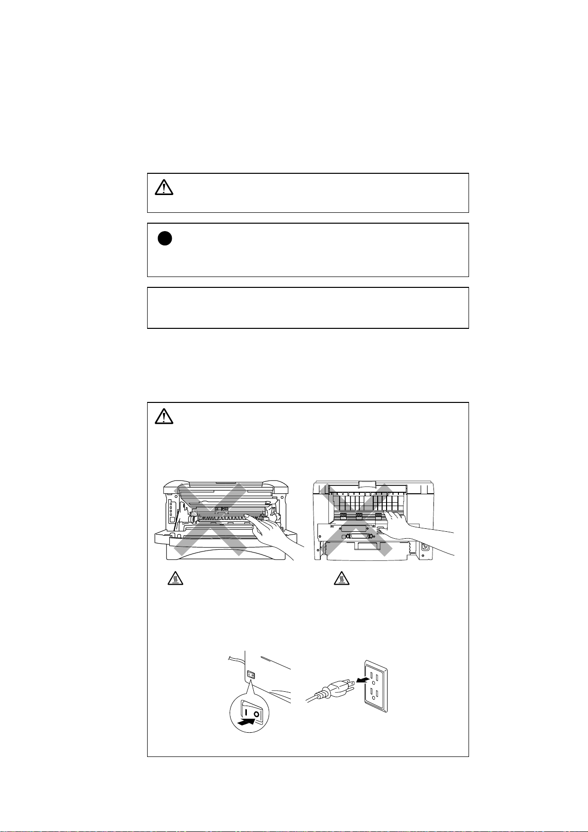
Warning
After you have just used the printer, some internal parts of the
•
•
• •
printer are extremely hot. When you open the front cover or rear
cover of the printer, never touch the shaded parts shown in the
following illustration.
High Temperature
•
Front view Rear view
Τhere are high voltage electrodes inside the printer. Before
cleaning the printer, make sure you have turned off the power swit ch
and unplugged the power cord from the power outlet.
High Temperature
Turning off the Power Switch and Unplug the Printer
Page 7
Shipment of the Printer
If for any reason you must ship your Printer, carefully package the Printer to avoid any
damage during transit. It is recommended that you save and use the original packaging. The
Printer should also be adequately insured with the carrier.
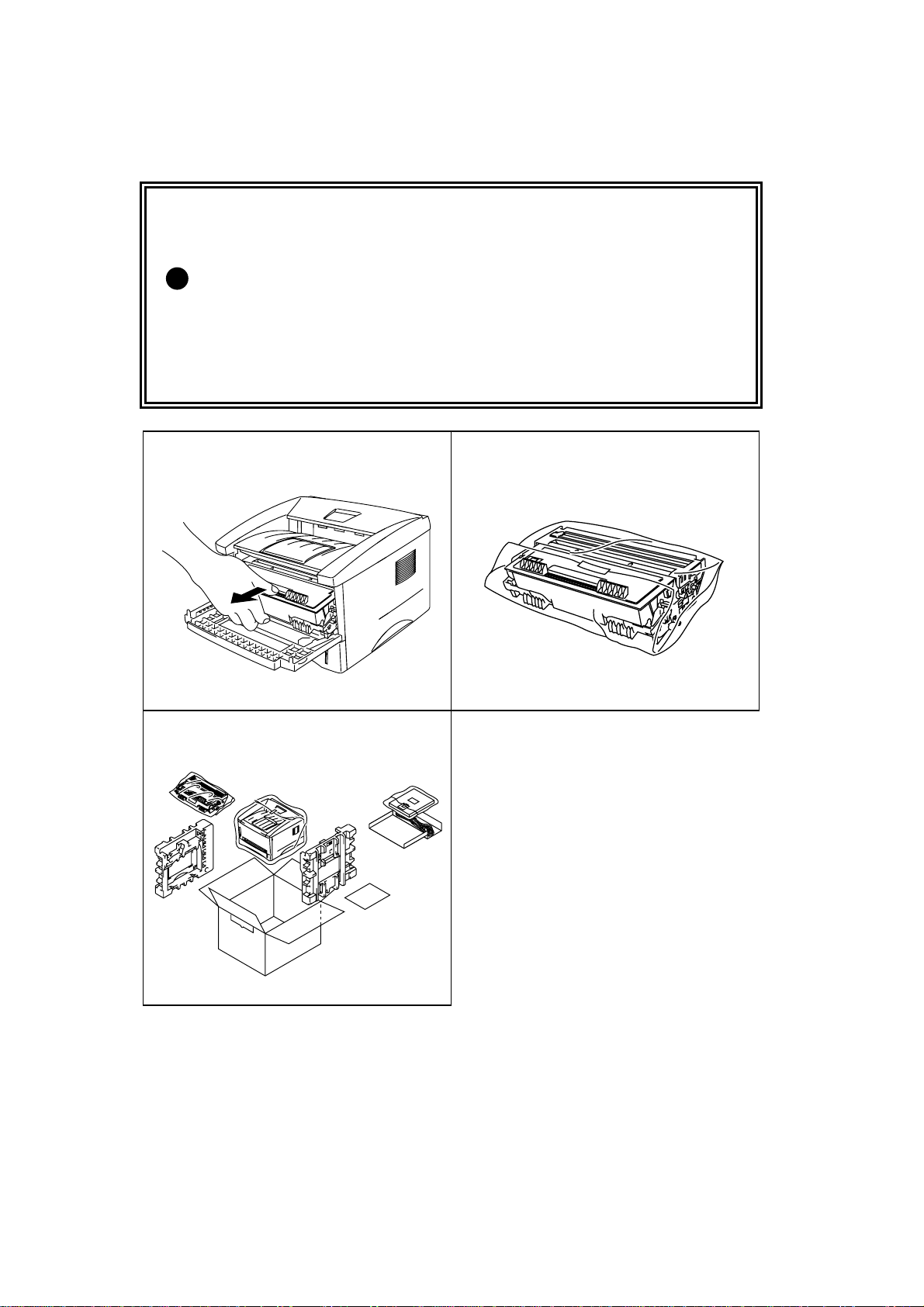
Caution
!
When shipping the Printer, the DRUM UNIT assembly including the TONER
CARTRIDGE must be removed from the Printer and placed in the plastic bag.
Failure to remove the unit and place it in the plastic bag during shipping
will cause severe damage to the Printer and will VOID THE
WARRANTY.
1 Remove the drum unit assembly.
3 Remove the AC cord from the
printer. Re-pack the printer.
2 Place it in the plastic bag and seal
the bag completely.
Page 8

(For USA & CANADA Only)
For technical and operational assistance, please call:
In USA 1-800-276-7746 (within US)
In CANADA 1-800-853-6660
514-685-6464 (within Montreal)
If you have comments or suggestions, please write us at:
In USA Printer Customer Support
Brother International Corporation
15 Musick
Irvine, CA 92618
In CANADA Brother International Corporation (Canada), Ltd.
- Marketing Dept.
1, rue Hôtel de Ville
Dollard-des-Ormeaux, PQ, Canada H9B 3H6
TABLE OF CONTENTS
BBS
For downloading drivers from our Bulletin Board Service, call:
In USA 1-888-298-3616
In CANADA 1-514-685-2040
Please log on to our BBS with your first name, last name and a four digit number for
your password. Our BBS supports modem speeds up to 14,400, 8 bits no parity, 1 stop
bit.
Fax-Back System
Brother Customer Service has installed an easy to use Fax-Back System so you can get
instant answers to common technical questions and product information for all Brother
products. This is available 24 hours a day, 7 days a week. You can use the system to
send the information to any fax machine, not just the one you are calling from.
Please call 1-800-521-2846 (U.S.A) or 1-800-681-9838 (Canada) and follow the voice
prompts to receive faxed instructions on how to use the system and your index of FaxBack subjects.
DEALERS/SERVICE CENTERS (USA only)
For the name of an authorized dealer or service center, call 1-800-284-4357.
SERVICE CENTERS (Canada only)
For service center addresses in Canada, call 1-800-853-6660
INTERNET ADDRESS
For technical questions and downloading drivers:
http://www.brother.com
Page 9
CHAPTER1 ABOUT THIS PRINTER
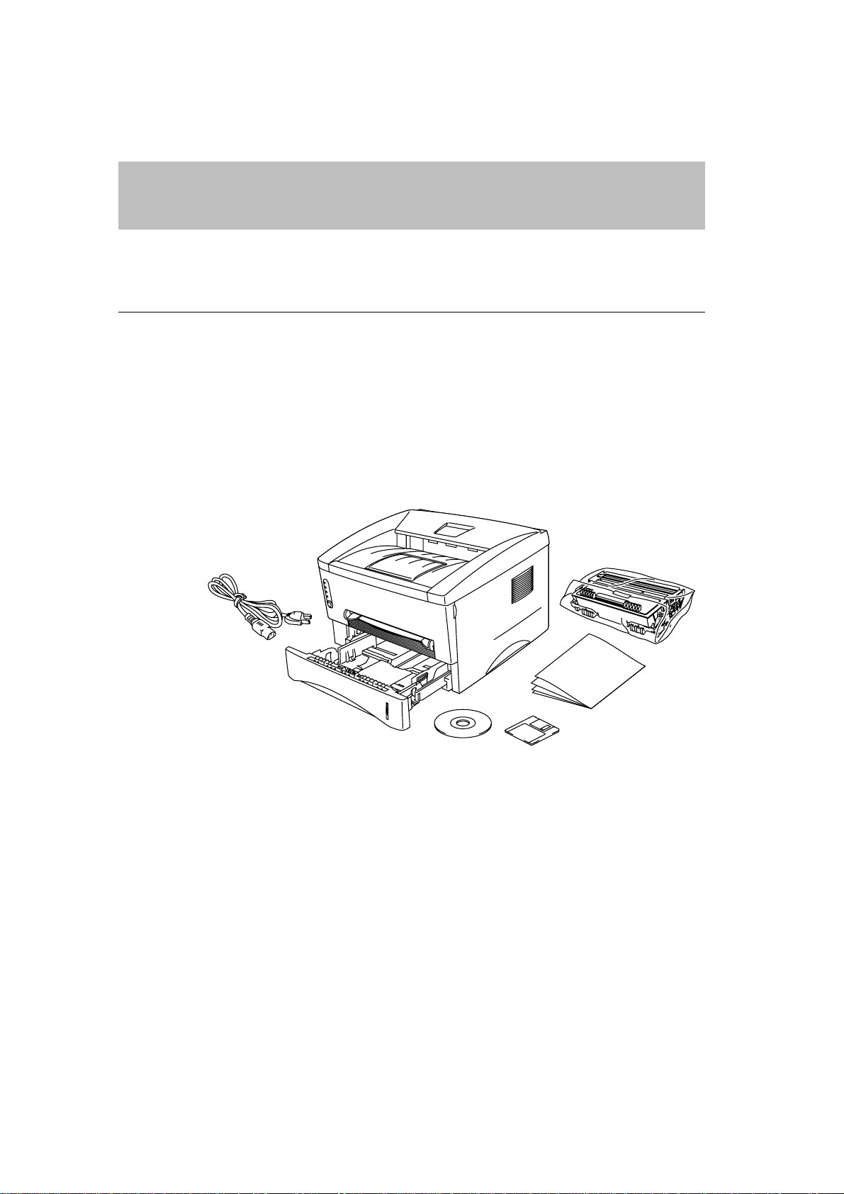
What is included in the carton
Components
When you unpack the printer, check to see th at you have all of the following parts:
CHAPTER 1 ABOUT THIS PRINTER
Drum unit assembly
(with toner cartridge included)
AC power cord
Components may differ from one country to another.
Printer
CD-ROM
Fig. 1-1 Components in the Printer Carton
Floppy
disk
Documents
1-1
Page 10
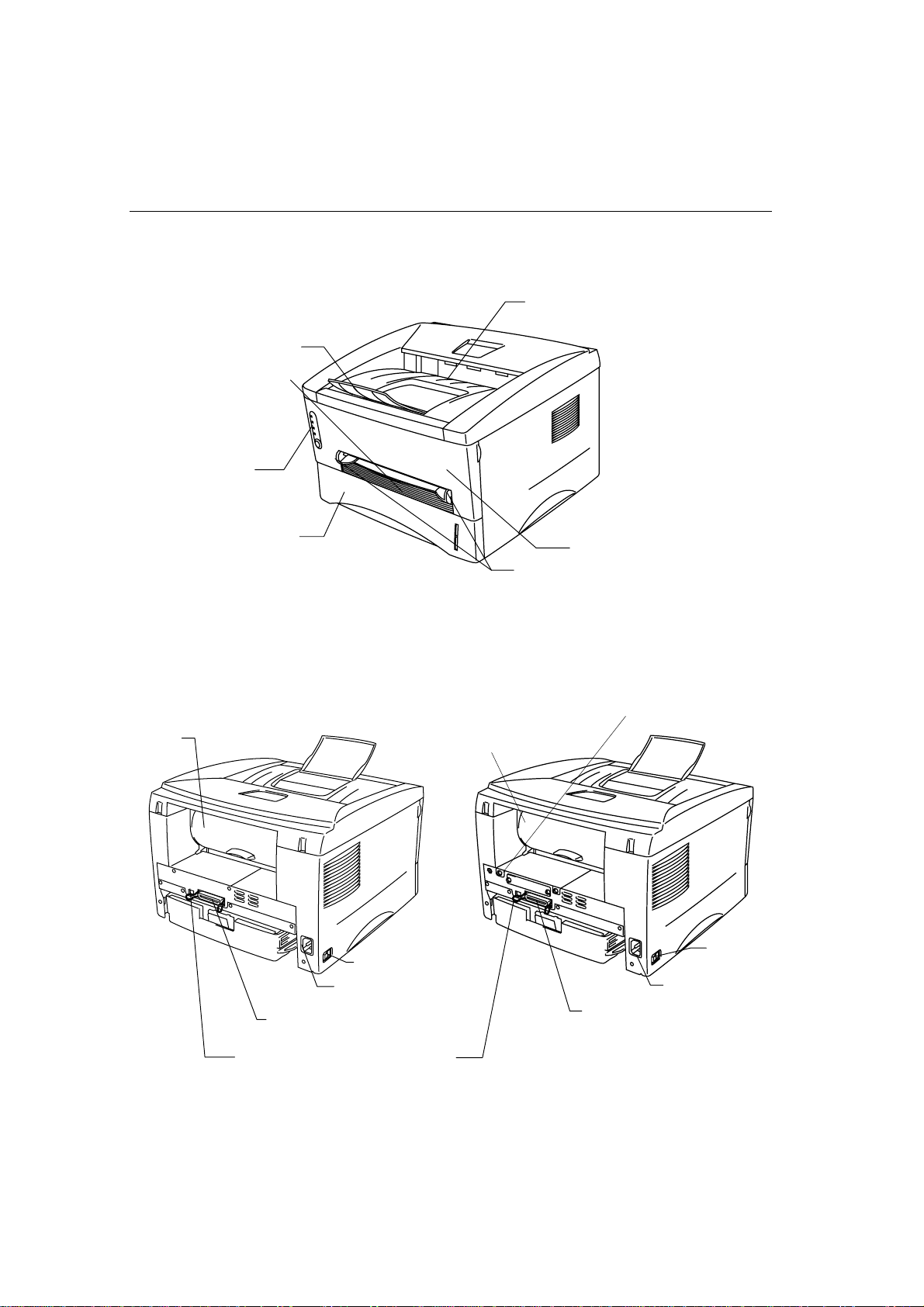
About your printer
Tray extension flap
Manual feed slot
Control panel
Face down output tray
Rear cover
Paper cassette
Fig. 1-2 Front View
Powerswitch
AC power inlet
Front cover
Manual feed paper guides
Modular jack for lower tray unit
Rear cover
Powerswitch
AC power inlet
Parallel Interface connector
USB (Universal Serial Bus Interface)
connector (HL-12401250 Only)
Fig. 1-3 HL-1030/1240 Rear View Fig. 1-4 HL-1250 Rear View
1-2
Parallelinterfaceconnector
Page 11

Features of your printer
❏ High Resolution and Fast Printing Speed
HL-1030 :
True 600 x 600 dots per inch (dpi) (GDI mode), with microfine toner and up
to 10 pages per minute (ppm) print speed (A4 or Letter paper).
HL-1240 :
True 600 x 600 dots per inch (dpi) (GDI mode), True 300 x 300 dots per inch
(dpi) (PCL mode) with microfine toner and up to 12 pages per minute (ppm)
print speed (A4 or Letter paper).
HL-1250 :
True 600 x 600 dots per inch (dpi) and 1200 x 600 dpi for graphics with
microfine toner and up to 12 pages per minute (ppm) prin t speed (A4 or
Letter paper).
CHAPTER 1 ABOUT THIS PRINTER
❏ Front Operation
Basic operation of the printer can be done from the front panel.
❏ Versatile Paper Handling
This printer loads paper automatically from the paper cassette. The paper
cassette can hold A4, letter, B5, Executive, A5 and A6 sizes of paper. The
manual feed slot allows manual paper loading sheet by sheet so you can use a
variety of types and sizes of paper. For ad di tional information, see “What kind
of paper can I use” in Chapter 1.
❏ Enhanced Printing Performance and User-Friendly Operation
for Windows
The dedicated printer drivers for Microsoft® Windows® 95/98, Windows 3.1 and
Windows NT 4.0 are available on the CD-ROM supplied with your printer. You
can easily install them into your Windows system using our installer program.
The driver supports our uniq ue compression mode to enhance the printing speed
in Windows applications and allows you to cho ose vari ous printer settings
including toner save mode, custom paper size, sleep mode, gray scale
adjustment, resolution and many layout functions. You can easily set these print
options through the Printer Setup Menu.
®
1-3
Page 12

❏ Quick Print Setup
You can easily make changes to settings which you need to change frequently in
a small selection window on your screen.
❏ Remote Printer Console Program for DOS
(For HL-1240/1250 Only)
The Remote Printer Console (RPC) utility program is avail able on the CD-ROM
supplied with your printer. When you operate your computer in a DOS (Disk
Operating System) environment, this program all ows you to easily change the
default settings of the printer such as fonts, page setup, and emulations.
This program also provides a status monitor program, which is a Terminate-andStay Resident (TSR) program. It can monitor the printer status while running in
the background and report the current status or errors on your computer screen.
❏ Popular Printer Emulation Support (For HL-1240/1250 Only)
These printers support the following popular printer emulation modes.
The HL-1240 supports HP LaserJet IIP (PCL4).
The HL-1250 supports HP LaserJet 6P (PCL6), Epson FX-850 and IBM
Proprinter XL. When you use DOS application software or Windows version
3.0 or earlier, you can use any of these emulations to opera te the printe r. The
printer also supports auto-emulation switching between HP and Epson or HP and
IBM. If you want to select the printer emulation, you can do it using the Remote
Printer Console Program.
❏ Printer Status Monitor with Bi-directional Parallel Interface
The printer driver can monitor the status of your printer using bi-directional
parallel communications. IEEE-1284 bi-directional parallel printer cable is
recommended.
The printer status monitor program can show the current status of your printer.
When printing, the animated dialog box appears on your computer screen to
show the current printing process. If an error occurs, a dialog box will appear to
let you know what to correct. For example: when your printer is out of paper,
the dialog box will display “No Paper” and instructions for the proper
corrective action.
1-4
Page 13

CHAPTER 1 ABOUT THIS PRINTER
❏USB Interface (For Windows 98, iMac and Power Macintosh
G3 with USB users Only) (For HL-1240/1250 Only)
This printer can be connected using the USB (Universal Serial Bus) Interface to
a PC which has a USB interface. Drivers to allow you to use the USB port are
provided on the CD-ROM supplied with the printer.
❏High Resolution Control & Advanced Photoscale Technology
(For HL-1250 Only)
High resolution control (HRC) technology provide s clea r and crisp printouts.
Use this function to get smooth text print quality.
Advanced Photoscale Technology (APT) enables the printer to print graphics in
256 grayscales, producing nearly photog raphi c quality. Use this function when
you want to print photographic images.
❏Enhanced Memory Management
The printer provides its own data compression technology in the printer
hardware and the supplied printer driver software, wh ic h can automatically
compress graphic and font data efficiently into the printer’s memory. You can
avoid memory errors and print most full page 600 dpi g ra p hic and text data,
including larger fonts, with the printer’s standard memory.
1-5
Page 14

❏Environment-Friendly
Economy Printing Mode
This feature will cut your printing cost by saving toner. It is useful to obtain
draft copies for proof-reading. You can select from two economy modes—25%
toner saving and 50% toner saving—through the Windows prin te r driver
supplied with your printer.
Sleep Mode (Power Save Mode)
When the printer is not used for a certain period of time, sleep mode
automatically reduces power consumption. The HL-1030/1240 consumes less
than 5 Watts, the HL-1250 consumes less than 6 Watts when in sleep mode.
Low Running Cost
Since the toner cartridge is separate from the drum unit, you need to replace only
the toner cartridge after approximately 3,000 pages, which is both cost effective
and ecologically friendly. (
up to 6,000 pages can also be used in this printer.
The actual number of pages printed with a toner cartri dge may vary depending
on your average type of print job, the figu res quoted are based on 5% coverage
per page.
You can print up to 20,000 pages with the drum unit, however there are many
factors that determine the actual drum life.
An optional high capacity toner unit that will print
)
❏Bar Code Print (HL-1250 Only)
This printer can print the followin g 11 types of bar codes:
• Code 39 • UPC-E
• Interleaved 2 of 5 • Codabar
• EAN-8 • US-PostNet
• EAN-13 • ISBN
• UPC-A • Code 128
• EAN-128
1-6
Page 15

What printer options are available
❏ External Print Server (Brother NC-2010p)
An optional Network print server Brot he r NC-201 0p is avai lable, which allows
your printer to be connected to your N e twork via the parallel interface. See
“What is the Brother print server (NC-2010p)” in Chapter 2
Lower Tray Unit (LT-400) (HL-1250 Only)
A lower tray unit expands the paper source capacity. You can load extra paper
and switch between the upper and lower paper sources automatically. See “The
Lower Tray Unit” in Chapter 2.
CHAPTER 1 ABOUT THIS PRINTER
❏ Serial Interface (RS-100M) (HL-1250 Only)
To connect the printer to a computer or a Unix work stati on wi th a serial interface
or to an Apple Macintosh computer, you need to inst all the optional interface
board (RS-100M). See “How to use the SERIAL INTERFACE (RS-100M)
connection” in Chapter 2.
❏ SIMM (Memory) (HL-1250 Only)
The printer has 4.0 Mbytes of standard memory and one slo t for optional
additional memory. The memory can be ex pand ed up to 36 Mbytes by installing
a commercially available single in-line memory modules (SIMM). It is
recommended to add memory if you want to print graphics at higher resolutions.
1-7
Page 16

Place the printer
Please take note of the following before using the printer.
Power Supply
• Use the printer within the specified power range.
AC power: ±10% of the rated power voltage in your country
Frequency: 50 Hz (220 V– 240 V) or 50/60 Hz (110–120 V)
Check the rating plate on the back of the printer for your model’s
specification.
• The power cord, including extensions, should not exceed 5 meters (16.5 feet).
• Do not share the same power circuit with other high-power appliances,
particularly an air conditioner, copier, shredder and so on. If it is unavoidable
that you must use the printer with these appliances, it is recommended that you
use an isolation transformer or a high-fre quency noise filter.
• Use a voltage regulator if the power source is not stable.
Environment
• The printer should be installed near a power outlet, which is easily accessible.
• Use the printer only within the followin g ranges of temperature and humidity.
• The printer should be used in a well ventilation room.
• Place the printer on a flat, horizontal surface.
• Keep the printer clean. Do not place the printer in a dusty place.
• Do not place the printer where the ventilation hole of the printer is obstructed.
• Do not place the printer where it is exposed to direct su nlight. Use a blind or a
• Do not place the printer near devices that contain magn et s o r generate magnetic
• Do not subject the printer to strong physical shocks or vibrations.
• Do not expose the printer to open flames or salty or c orrosive gasses.
• Do not place objects on top of the printer.
• Do not place the printer near an air conditioner.
• Keep the printer horizontal when carrying.
• Do not cover the slots in the top cover.
Ambient temperature: 10°C to 32.5°C (50°F to 90.5°F)
Ambient humidity: 20% to 80% (without condensation)
Keep a gap of approximately 100 mm (4 inches) between th e ventilation hole
and the wall.
heavy curtain to protect the printer from direct s unli g ht when the printer is
unavoidably set up near a window.
fields.
1-8
Page 17

CHAPTER 1 ABOUT THIS PRINTER
System Requirements for the Brother Printing Solution for Windows
Check the following system requirements to setup and operate the pr inter in Brother
Printing Solution for Windows:
• IBM PC or compatible with 80486 SX or higher micr oprocessor
• 10 MB of space available on your hard disk for the printer driver and all fonts
• Microsoft Windows 3.1/3.11, Window s 95/98 or Windows NT 4.0
1-9
Page 18
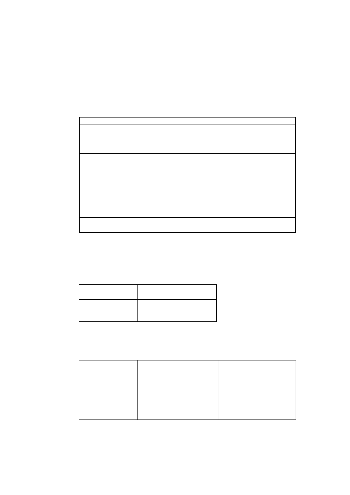
What kind of paper can I use
Media Type
Paper type Paper size
Paper cassette (standard) cut sheet
Transparencies
Manual feed slot cut sheet
envelope
organizer
Transparencies
Labels
other sizes
Optional lower paper
cassette (For HL-1250 Only)
cut sheet letter, A4, ISO B5, Executive, A5
letter, A4, ISO B5, Executive, A5,
A6, and legal (US and Canada
Only)
A4, Letter
letter, A4, B5 (JIS/ISO), Executive,
A5, A6, legal
COM 10, Monarch, C5, DL and
ISO B5
Day-Timer
A4, Letter
A4, Letter
70-216 x 116-356 mm,
2.75-8.5 x 4.57-14 inches
and legal (US and Canada Only)
®
J, K, L
Paper Specification
Paper Cassette
Cut Sheet
Basis Weight 64 to 105 g/m2 (17 to 28 lb.)
Caliper 0.08 to 0.13 mm
(0.003 to 0.005 in.)
Moisture Content 4 % to 6% by weight
Manual Feed Slot
Cut Sheet Envelope
Basis Weight 64 to 158 g/m2 (17 to 43 lb.) 75 to 90 g/m2 single thickness
(20 to 24 lb.)
Caliper 0.08 to 0.2 mm
(0.003 to 0.008 in.)
Moisture Content 4% to 6% by weight 4% to 6% by weight
0.084 to 0.14 mm
(0.003 to 0.005 in.)
single thickness
1-10
Page 19

• We recommend you use labels or transparencies which are designed for use in
• The printing speed may change, dep ending on the paper size and the media type
Paper Capacity
Upper Paper Cassette
A4/Letter paper: Approx. 250 sheets of 80 g/m
Transparencies 10 sheets
Note
laser printers.
in use, in order to avoid damage to the printer.
(21 lb.)
CHAPTER 1 ABOUT THIS PRINTER
2
Up to 27 mm (1.06 inch) in
height (up to the mark)
Face down printing into the output tray
A4/Letter paper: Approx. 150 sheets of 80 g/m2 (21 lb.)
Face up printing out of the rear of the printer
Thicker paper: Single sheet of thicker paper
Recommended Paper
Cut sheet: Xerox 4200 (in USA) /
Xerox 80 Premier Paper (in Europe) or
equivalent
Label: Avery laser label or equivalent
Transparencies: 3M CG3300 or equivalent
1-11
Page 20

Remarks
It is recommended that you test paper, especially special sizes and types of paper
and heavy paper, on this printer before purchasing large quantities.
Avoid using coated paper, such as vinyl coated paper.
Avoid using preprinted or highly textured paper.
Use a recommended type of paper, especially pl ai n paper and transparencies, for
optimum printing. For more information on paper specifications, consult your
nearest authorized sales representative or the place you purchased your printer.
If the paper has problems feeding from t h e paper cassette, use the manual feed slot
and try again.
Use neutral paper. Do not use acid paper to avoid any damage to the printer drum
unit.
Make sure that you have selected the appropriate media type in the printer driver for
optimum printing.
The print quality might be degraded or th e li fe of the drum unit might be shortened
with the following usage. Using the printer for speci a l pri nt jo bs for lon g periods of
time (i.e. printing name cards, etc.)
Cut Sheet
We recommend you use long-grained p aper for the best print quality.
If you are using short-grained paper, it may be the cause of paper jams.
Labels / Transparencies
Avoid feeding labels with the carrier shee t exposed, or your printer will be
damaged.
We recommend you use labels or transparencies which are designed for use in laser
printers.
1-12
Page 21

Special Paper
Before using paper with holes, such as organizer shee ts, you must fan the stack well
to avoid paper jams and misfeeds.
Do not use organizer sheets that are stuck together. The glue that is used might
cause damage to the printer.
Before using any paper, make sure that it is not curled. If it is, you should straighten
the paper as much as possible. Feeding curled paper ca n cause paper jams and
misfeeds.
CHAPTER 1 ABOUT THIS PRINTER
Fig. 1-5 Fan the Paper and
Straighten the Paper
Different types of paper should not be loaded at the sa me time in the paper cassette,
it may cause paper jams or misfeeds.
1-13
Page 22
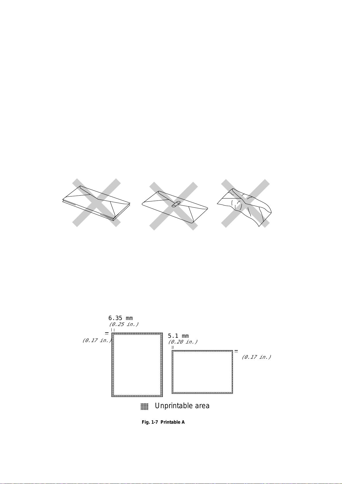
Envelopes
,
,
,
,
,
The following types of envelopes are not rec o mmended for use.
• Damaged, curled, wrinkled, or irregularly shaped envelopes
• Extremely shiny or highly textured envelopes
• Envelopes with clasps
• Envelopes with self-adhesive closures
• Envelopes of baggy construction
• Envelopes not sharply creased
• Embossed envelopes
• Envelopes already printed by a laser printer
• Envelopes pre-printed on the inside
• Envelopes that cannot be arranged uniformly when placed in a pile
Printable Area
The figure below shows the physically printable area.
4.2 mm
(0.17 in.)
6.35 mm
(0.25 in.)
Fig. 1-6 Envelopes
5.1 mm
(0.20 in.)
,,,,,,
,,,,,,
,,,,,,
,,,,,,
Unprintable area
,,,,,,
4.2mm
(0.17 in.)
Fig. 1-7 Printable Area
1-14
Page 23
CHAPTER 1 ABOUT THIS PRINTER
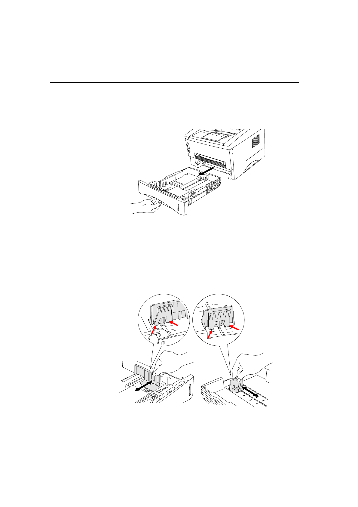
How to load paper into the Paper Cassette
Pull the paper cassette completely out of the printer.
1.
Fig. 1-8 Pull out the paper cassette
Adjust the paper guides at the right and rear of the paper ca sset te to match the paper
2.
size you want to load. Make sure that the t i p of t he paper gu ides fit into the slots
correctly.
Fig. 1-9 Adjust the paper guides
1-15
Page 24
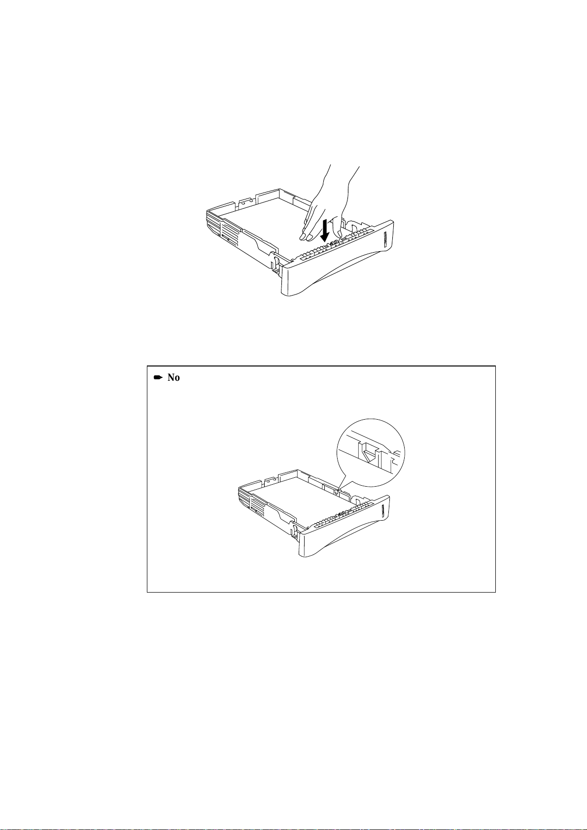
Load paper into the paper cassette. Make sure that the paper is flat in the cassette at
3.
all four corners.
Fig. 1-10 Load the paper
Note
Do not load more than 250 sheets of paper (80 g/m2) in the cassette, or paper jams
may occur. Paper should be loaded up to the line s o n the sliding guide.
Fig. 1-11 Paper Lines
1-16
Page 25
CHAPTER 1 ABOUT THIS PRINTER
Install the paper cassette into the printer. Make sure it is inserted fu lly into the
4.
printer.
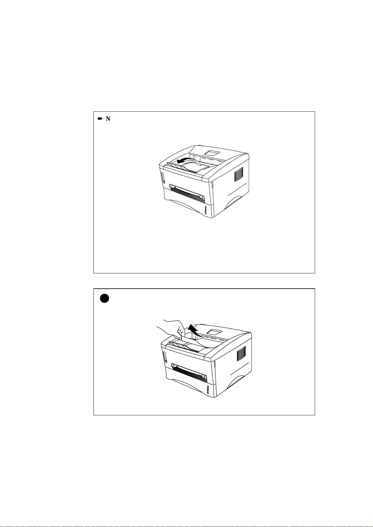
Note
• Extend the Output tray extension flap to preve nt the paper from sliding off the
face down output tray.
Fig. 1-12 Extend the Output tray extension flap
• We recommend that you remove printed pages immediately after printing if you
choose not to extend the Output tray extension flap.
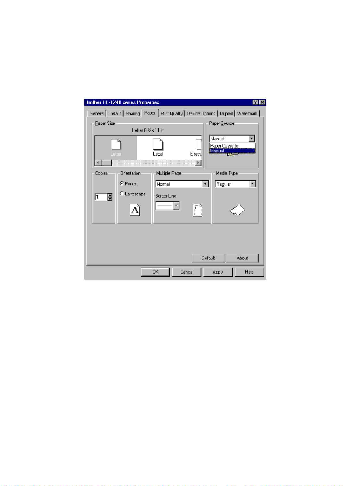
Caution
!
Remove each sheet immediately especially when you use transparencies.
Fig. 1-13 Remove each sheet
1-17
Page 26

How to load a sheet of paper manually
Note
• Insert the paper into the manual feed slot using both hands.
• The printer turns the manual feed mode on automa ti ca ll y when yo u insert paper
into the manual feed slot.
• If the paper you are printing is between A4 and A6 in size, and between 64 g/m
and 105 g/m2 we recommend that you use the paper cassette.
You may also view the technique of loading one sheet of paper manually in the
instructional video on the supplied CD-ROM.
2
1-18
Page 27
CHAPTER 1 ABOUT THIS PRINTER
Select manual feed mode in the printer driver.
1.
<Windows 95 / 98 and Windows 3.1>
1-19
Page 28

<Windows NT4.0>
Send the print data to the printer.
2.
Note
A “NO PAPER” message is shown in the Statu s Monitor until you insert a sheet of
paper into the manual feed slot.
Fig. 1-14 Select manual feed mode
Drum
Ready
Paper
Alarm
Toner
Data
Fig. 1-15 No paper
1-20
Page 29
CHAPTER 1 ABOUT THIS PRINTER
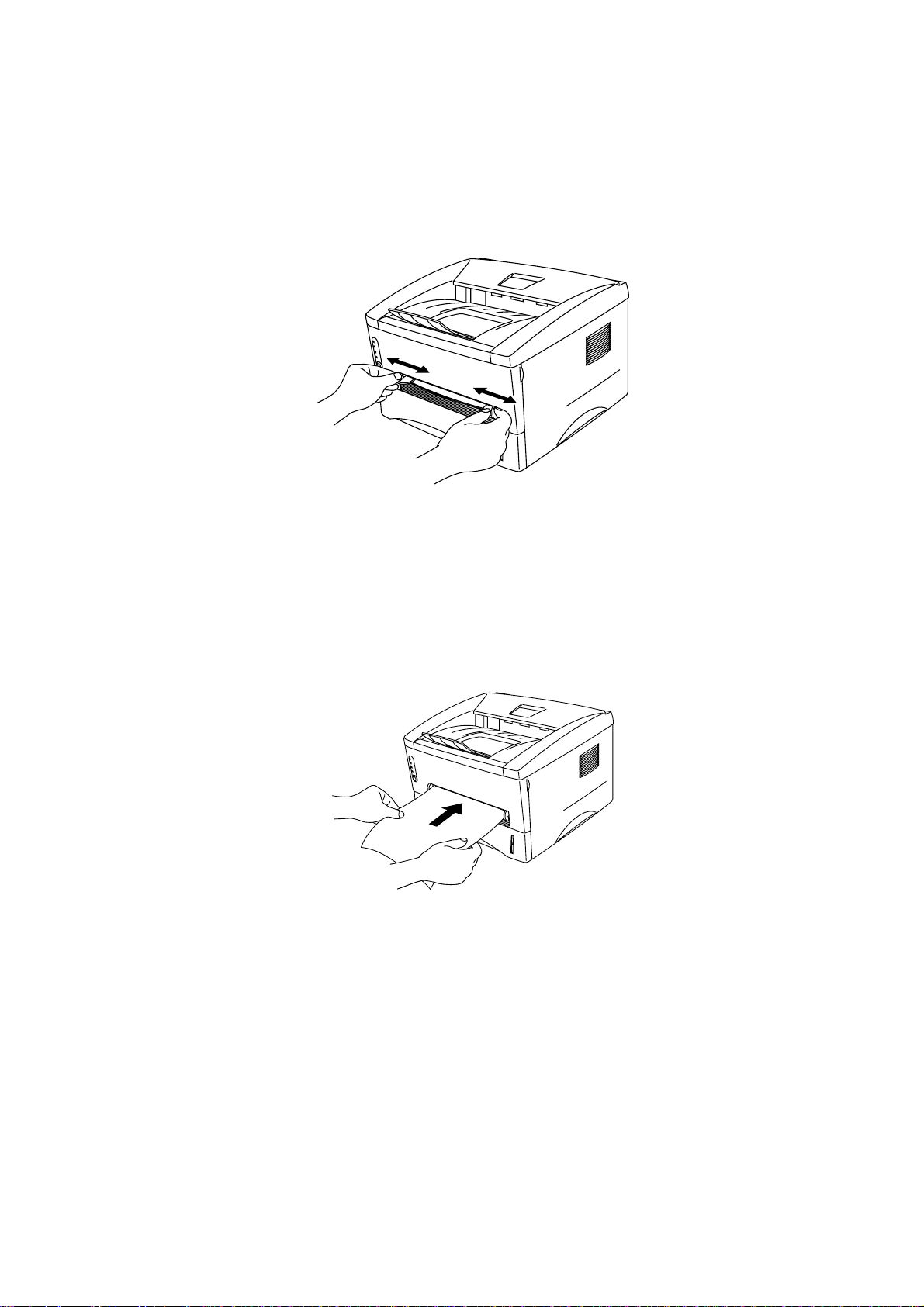
Set the width of the manual feed slot paper guides using both hands to the paper
3.
width to be used.
Fig. 1-16 Set the width of the manual feed slot paper guides
Insert the paper into the manual feed slot with both hands until the front edge of the
4.
paper touches the paper feed roller. Hold the paper in this position until the printer
feeds the paper in automatically a short distance and then let go of the paper.
Fig. 1-17 Insert the paper
After the printer ejects the printed page, insert the next sheet of paper as in step 4
5.
above. The printer will wait until you insert the next shee t of paper. Repeat this as
necessary for the number of pages you need to print.
1-21
Page 30
To print on thicker paper and card
The printer has a straight paper path from the manual feed slot to the rear of the
printer when the rear cover is lifted upwards. Use this paper feed and output
method when you want to print on thicker paper or card.
Select manual feed mode in the printer driver.
1.
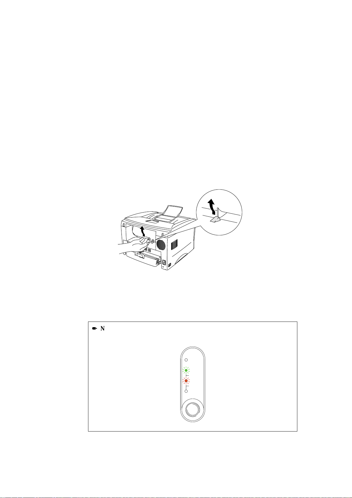
Lift up the rear cover at the rear of the printer.
2.
Fig. 1-18 Lift up the rear cover
Send the print data as us ual.
3.
Note
A “NO PAPER” message is shown in the Statu s Monitor until you insert a sheet of
paper into the manual feed slot.
Drum
Ready
Paper
Alarm
Toner
Data
Fig. 1-19 No paper
1-22
Page 31

CHAPTER 1 ABOUT THIS PRINTER
Set the width of the manual feed paper guides using both hand s to the paper width
4.
you want to use.
Insert the paper into the manual feed slot with both hands until the front edge of the
5.
paper touches the paper feed roller. Hold the paper in this position until the printer
feeds the paper in automatically a short distance and then let go of the paper.
After the printer ejects the printed page, insert the next sheet of paper as in step 5
6.
above. The printer will wait until you insert the next sheet of paper. Repeat this as
necessary for the number of pages you need to print.
Close the rear cover of the printer.
7.
Caution
!
• Remove each sheet immediately after printing. Stacking the sheets may cause
curl or media feed jams.
Fig. 1-20 Remove each sheet immediately
1-23
Page 32

How to print on both sides of the paper (Manual Duplexing)
The supplied printer drivers for Windows 95/9 8, Windows 3.1 and Windows NT 4.0
all enable manual duplex printing. For more information about how to make the
settings, see the Help text in the printer driver.
Guidelines for printing on both sides of the paper
1 It may cause wrinkling if the paper is too thin.
2 If paper is curled, straighten it and then set it into the paper cassette.
3 The paper type should be regular paper. Do not use bond paper.
4 When setting paper into the paper cassette, empty the cassette first, then insert
the printed paper only, printed side face u p. (D o not add the printed paper onto
the top of the unprinted paper st ack.)
5 If the paper is not feeding correctly, it is possible that the paper is curled, remove
the paper and straighten it.
1-24
Page 33

CHAPTER 1 ABOUT THIS PRINTER
To print on both sides of the paper from the paper cassette
Select the required manual duplex printing mode from the driver.
1.
The printer will automatically print all the even numbered pages on one side of the
2.
paper first.
Remove the printed even numbered pages from the output tray and re-insert them
3.
into the paper cassette, loading the paper with the side to be printed (bl a nk side) face
down, and the top edge toward you. Follow the in structions on the computer screen.
Fig. 1-21 Paper orientation for the paper cassette
The printer will now automatically print all the odd pages on the reverse side of the
4.
paper.
1-25
Page 34

To print on both sides of the paper from the manual feed slot
Caution
!
• Before re-inserting the sheets, you have to straighten t h em , or you may get paper
feed errors.
• The use of very thin or very thick paper is not recommended.
• When you use the Manual Duplex function, it is possible that paper jams may
occur or print quality might not be satisfactory. If a paper jam has occurred,
please refer to “PAPER JAMS and how to clear them” in Chapter 4.
Select the required manual duplex printing mode and manual feed mode from the
1.
driver.
2.
3.
Using both hands, insert the paper into the manual feed slot with the side to be
printed first facing upwards.
Follow the instructions on the computer screen.
Repeat this until you have printed all the e ven numbered pages.
Remove the printed even numbered pages from the output tray and re-insert them in
order into the manual feed slot, loading the paper with the side to be printed (blank
side) face up, and the top of the pr inted side towards the printer. Follow the
instructions on the computer screen.
Fig. 1-22 Paper operation for the manual feed slot
Repeat action 3 until you have printed all the odd numbered pages on the reverse
4.
side of the paper.
1-26
Page 35

What do the LED indications mean
This section refers to the following LED and button on the printer control panel.
The LED indications as shown in the table below are used in the illustrations in this
chapter.
CHAPTER 1 ABOUT THIS PRINTER
❍
LED is Off
LED is Blinking
LED is On
Drum
Ready
Paper
Alarm
Toner
Data
Fig. 1-23 LEDs and Button on the Control Panel
Note
✒
When the power switch is off or the printer is in sleep mode, all LEDs including the
Ready LED are off.
1-27
Page 36

Ready (Paper) LED indications
The Ready LED indicates the current status of the printer.
LED Printer status
Off
❍
Blinking (Blinking at 1 second intervals)
On
The power switch is off or the printer is in sleep mode. If the printer
is in sleep mode, it will wake up automatically when it receives data
or when you press the control panel button.
The printer is warming up.
(Blinking at 2 seconds intervals)
The printer is cooling down and stop s printing until the internal
temperature of the printer lowers.
The printer is ready to print.
This LED also works as the Paper LED with the Alarm LED. They blink
simultaneously to indicate a paper error
LED Error Action
Paper jam Clear the paper jam referring to
Chapter 4 “PAPER JAMS and How to
Drum
Ready
Paper
Alarm
Toner
Data
clear them” and press the panel button
if the printer does not automatically
resume printing.
No paper Load paper in the printer referring to
“How to load paper into the Paper
cassette” in Chapter 1 and press the
panel button.
Misfeed Reinstall the paper and press the panel
button.
1-28
Page 37

Data (Toner) LED indications
The Data LED indicates the current status of the prin t da ta p r ocess.
LED Printer status
Off
❍
Blinking The printer is receiving data from the compute r or the printer is
The printer has no print data.
processing data in memory.
CHAPTER 1 ABOUT THIS PRINTER
On
Print data remains in the printer memory. If the Data LED is on for a
long period of time and nothing has printed, you need to press the
button to print the remaining data.
1-29
Page 38

This LED also works as the Toner LED with the Alarm LED. They blink
simultaneously to indicate a toner error. See “How to replace the Toner cartridge”
in Chapter 3 .
LED Error Action
Toner low Indicates that the toner cartridge is
nearly empty. Purchase a new toner
Drum
Ready
Paper
Alarm
Toner
Data
cartridge and have it ready for when
Toner empty is indicated.
Blinking every 5
seconds
Toner empty Replace the toner cartridge with a new
one referring to Chapter 3.
Drum
Ready
Paper
Alarm
Toner
Data
1-30
Page 39

Drum LED indications
The Drum LED indicates the Drum unit is nearly at the end of its life.
LED Printer status
Off
❍
On
●
The drum unit can be used.
The drum unit is nearly at the end of its life. We recommend you to
obtain a new drum unit to replace the current one. See “How to
replace the drum unit” in Chapter 3.
Alarm LED indications
CHAPTER 1 ABOUT THIS PRINTER
The Alarm LED blinks (with no other LEDs) to indicate a prin ter erro r statu s such
as “COVER OPEN” or “MEMORY FULL.” If any other error occurs, the printer
indicates the error by blinking the Alarm LED with another LED or by printing an
error report. For additional information, see “Control Panel Indications” in Chapter
4.
1-31
Page 40

Control Panel Button Operations
The control panel button is used for the following purposes depending on the
situation.
Cancel Printing
If you press the button during printing, the printer immediately stops printing and
ejects the paper.
Wake-Up
If the printer is in sleep mode, pressing the button wakes it up into the ready state. It
will take up to 45 seconds for the printer to go into the Ready state.
Form Feed
If the Data LED is on, press the button. The printer prints any data remaining in the
printer memory: this operation is called “Form Feed.”
Error Recovery
If an error occurs, the printer will recover from some e rrors automatically. If the
error does not clear automatically, p r ess the b utton to clear the error and continue
printer operation.
1-32
Page 41

Other Control Features
The printer has the following useful features:
Sleep Mode
When the printer does not receive data for a certain period of time (timeout), it
enters sleep mode. Sleep mode acts as though the printer was turned off. The
default timeout is 5 minutes and it is automatically adjusted to the most suitable
time-out setting depending on the frequency of your printer use (Intelligent Sleep
Mode). While the printer is in sleep mode, all the LEDs are off and it is as if it was
turned off, but the printer can still receive data from t h e computer. Receiving a print
file or document automatically wakes up the printer to start printing. Pressing th e
button also wakes up the printer.
CHAPTER 1 ABOUT THIS PRINTER
Note
✒
• When the printer goes into sleep mode, the fan will not stop until the printer
engine has cooled down.
• Sleep mode allows the print engine to cool, so the temperatur e of your room and
how long the printer has been in sleep mode affects the warm-up time. This
warm-up time can take up to 45 seconds. The Ready LED blinks to indicate that
the printer is warming up.
• You can change the timeout for the sleep mod e wit h the su pp lied pri n ter driver
(all models) or Remote Printer Console program. Refer to the Help section in
the printer driver or RPC program for more information about the sleep mode
setting.
1-33
Page 42

Test Print Mode
The printer has the following test print modes. Follow these steps:
Make sure that the front cover is closed.
1.
Hold down the control panel button and tu rn on th e power swi t ch. Kee p the button
2.
depressed until the Drum LED comes on.
The Drum LED illuminates to indicate that the printer is in the test print mode.
Release and then press the button again to ex ec ute th e test pri nt or ho ld down the
3.
button to select another option as shown in the table below and release the button to
execute the selected option.
LED Lit Choice Function
Drum
Ready
Alarm
Data
Test sample page The printer prints a test sample page.
The printer returns to the ready status after
printing.
Print Config &
Print Fonts I
Factory Reset The p r in ter is restor ed to the factory setting
Hex Dump Print The printer can print data as hexadecimal
The printer prints the current configuration
of the printer and a list of the internal fonts.
The printer returns to the ready status after
printing.
and permanent fonts and macros are
cleared.
The printer returns to the ready status after
printing.
values so that you can check data errors and
problems. To exit from this mode, you
have to turn off the printer.
1-34
Page 43

CHAPTER 2 OPTIONS
Optional Accessories and Supplies
This printer has the following optional accessories and supplies, and you can
increase the capabilities of the printer with these items.
Supplies
Item Information
1 Toner cartridge See page 3-3
2 Drum unit See page 3-9
3 Print Server See page 2-10
CHAPTER 2 OPTIONS
12 3
<For HL-1250 Only>
Item Features Information
1 Lower Tray Unit Paper feeder and
250 sheet tray
2 Serial Interface Connect the printer to the
computer serial port or to a
Unix workstation.
3 SIMM The memory can be expanded
up to 36 Mbytes
123
See page 2-2
See page 2-3
See page 2-11
2-1
Page 44

The Lower Tray unit (For HL-1250 Only)
The lower tray unit is an optional device that functions as a third paper source. It
can contain a maximum of 250 sheets of paper (80 g/m
To obtain the optional lower tray unit, please consult the dealer or store where you
purchased the printer.
Fig. 2-1 Loading Paper in the Lower Tray Unit
With the lower tray unit installed, load paper into the lower paper cassette in exactly
the same way as you load paper in the upper paper cassette.
2
).
The paper sizes that may be used in the lower paper cassette are not the same for the
upper paper cassette as shown below.
Paper type Available size Weight and capacity
Cut sheet letter, A4, ISO B5, Executive, A5
and legal (US and Canada Only)
Caution
!
If a paper jam occurs when using the lower tray unit, check for correct installation
of the paper cassette.
64 to 105 g/m2 plain
paper (17 to 28 lb.)
250 sheets
2-2
Page 45

How to use the SERIAL INTERFACE (RS-100M) Connection (For HL-1250 Only)
To connect the printer to a DOS computer with a serial interface or to an Apple
Macintosh computer with a serial interface, you need to install the optional serial
interface board (RS-100M). When you have installed the serial interface board, you
can share the printer between two computers (two IBM compatible PCs or one IBM
compatible PC and one Apple Macintosh) using the parallel and serial interfaces at
the same time. Automatic interface selection between the two connections is a
standard feature.
✒ Note
• The serial interface board for this printer is an option, but in some countries the
serial interface board may have been installed by either the factory or dealer.
• The serial interface for Apple Macintosh (RS-422A) will only print at 300 dpi.
CHAPTER 2 OPTIONS
The serial interface board is installed onto the main controller board inside the
printer. For installation details, see the instruct ion guide which is provided with the
serial interface board.
2-3
Page 46

How to select the RS-422A (Apple) or RS-232C (IBM) Serial Interface (For HL-1250 Only)
✒ Note
This section is only for printer models which have had the serial interface installed.
Caution
!
Be sure to select the serial interface type to match your computer as follows:
• For Apple Macintosh computers: you s hould not have to change any settings
because the Apple (RS-422A) setting is factory selected (default).
• For IBM compatible PCs you should move the switch to the IBM (RS-232C)
setting.
• If you are using an Apple Macintosh on the RS-422A port and an IBM
compatible PC on the parallel port, it is not n ecessary to make any changes to the
switch setting.
If necessary, select the interface type as follows:
Make sure that the printer is in the off-line state.
.
1
Select the RS-422A(Apple) or RS-232C(IBM) interface by changing the serial
.
2
interface slide switch to the right to select the IBM(RS-232C) in terface or to the left
to select the Apple(RS-422A) interface.
Fig. 2-2 Selecting the RS-422A (Apple) or RS-232C (IBM) Serial Interface
2-4
Page 47

How to set the Serial Interface Parameters
✒ Note
This section is only for printer models which have had the serial interface installed.
Caution
!
Be sure to set the parameters to match your computer as follows:
• Never change the RS-422A parameters for Apple Macintosh computers. The
RS-422A parameters have been correctly set at the factory for Apple Macintosh
computers, you do not need to change the settings. You may skip this section. If
you change parameters for the RS-232C serial interface and you switch back to
RS-422A for Apple Macintosh computers, be sure to res t ore the parameters to
the factory settings.
• Set the RS-232C parameters to match your computer. You can change the serial
settings for your PC in several different places; within your DOS application,
within the Windows Printer Icon (for Windows application software only) or
within your AUTOEXEC.BAT file using MODE commands. For info rmation on
serial interface parameters, see the user’s guide of your computer or software.
• Do not alter the dual in - line package (DIP) switch se ttings when the printer
power is on.
CHAPTER 2 OPTIONS
If necessary, set the serial interface parameters as follow:
Make sure that the printer is in the off- line state.
.
1
Set the serial interface parameters you require by referring to Table 1 below and by
.
2
moving up (on) or down (off) the selectors of the du al in-line package (DIP) switch.
The default settings for both RS-422A and RS-232C modes are all switches set to
OFF (down).
ON
12345678
Fig. 2-3 Setting the Serial Interface Parameters
2-5
Page 48

Table 1: Serial Interface Parameters Settings
Selector Parameters On (up) Off (down)
1 Baud Rate See Table 2
2 Baud Rate See Table 2
3 Data Length 7 bits 8 bits
4 Stop Bit 2 bits 1 bit
5 Parity See Table 3.
6 Parity See Table 3.
7 Protocol Xon/Xoff + DTR DTR only
8 Robust Xon On Off
Table 2: Baud Rate Settings
Selector 1 Selector 2 For RS-422A For RS-232C
Off Off 57600 9600
On Off 9600 4800
Off On 1200 1200
On On 19200 19200
Table 3: Parity Settings
Selector 5 Selector 6 Parity
On On Odd
On Off Even
Off Off None
✒ Note
• The factory settings are indicated in bold ( all switches OFF ).
• If the robust Xon setting is turned on with selector 8, the printer sends Xon
signals at one second intervals to the connected computer until it receives data. It
is effective only if selector 7 is set to the On position f or the Xon/Xoff plus DTR
setting.
2-6
Page 49

RS-100M Interface Connector
Pin Assignment
Pin No. Signal
1DTR DTR
2DSR DSR
3TxD TxD40V 0V
5RxD RxD6TxD+
7N.C.
8RxD+
CHAPTER 2 OPTIONS
687
354
12
Fig. 2-4 Interface Connector
IBM(RS-232C) Apple(RS-422A)
2-7
Page 50

How to connect the Serial Interface Cable
✒ Note
This section is only for printer models which have had the serial interface installed.
You need a serial interface cable with an 8-pin, DIN-type connector to connect your
printer and computer.
✒ Note
• Consult your dealer for a serial interface cable.
• If you are a Macintosh user, you can easily find the necessary cable at a local
computer store. Look for Apple serial cables labeled as “Macintosh to
StyleWriter” or “Macintosh to Personal LaserWriter LS” or the “Apple
System Peripheral 8 Cable”. Do not purchase a serial cable labeled as “Straightthrough” or “LocalTalk”.
• If you are a PC user, you need to purchase a special serial cable from your
dealer. If you have a 9-pin connector on y o ur computer, look for a cable labeled
“IBM AT to ImageWriter II” cable. If you have a 25-pin connector, look for a
cable labeled “DB25 to ImageWriter II.” These cables most likely would be
found in the Apple Macintosh section at your computer dealer. For more
information about the interface specification, consult your dealer.
You can connect a parallel and a serial interface cable at the same time. The auto
interface selection function allows you to share the printer with two computers. To
do this, connect the parallel interface cable and then connect the serial interface
cable as follows:
2-8
Page 51

CHAPTER 2 OPTIONS
Make sure that the power switch is turned off .
.
1
Caution
!
Be sure to turn off the power switch befo re connecting or disconnecting the
interface cables, or the printer may be damaged.
Insert and secure the parallel interface connector from the computer into the parallel
.
2
interface port of the printer.
Insert and secure the serial interface connector from the computer or Macintosh into
.
3
the serial interface port of the printer.
Turn on the power switch.
.
4
2-9
Page 52

What is the Brother print server (NC-2010p)
An optional Network print server Brother NC-2010p is available, which allows your
printer to be connected to your network via the parallel interface.
Brother print servers allow multiple host computers to share a Brother printer on a
10 Mbit Ethernet network. Any user can print their job as if the printer was directly
connected to their computer. No special software is required on the host computers
and users on DEC, UNIX, Novell, AppleTalk, LAN Server/Warp Server, Windows
NT, Windows 95/98, NetBIOS and Banyan VINES computers can simultaneously
access the same printer.
Features
The Brother print servers offers the widest range of feat ures in the industry,
including:
• LAT, TCP/IP, Netware, AppleTalk, NetBIOS, Banyan VINES and DLC/LLC
protocols
• Network Operating System compatibility:
- Digital Equipment Corporation networks, including PATHWORKS and
DECprint Server
- UNIX systems that support either the Berkeley lpr/lpd printing protocol,
printing to a raw TCP port
- Novell Netware V2.15 or above, V3.xx, or V4.xx, including support for
NetWare Directory Services (NDS)
- AppleTalk Phase 2
- Windows NT4.0 and NT3.5x
- IBM LAN Server V4.0 or above, or any earlier version that has IBM TCP/IP
V2.xx
- Windows 95/98 (Peer-to-Peer or client mode)
• Very high performance
• Superior network and printer management::
- BRAdmin and BRAdmin32 Windows-based Management utilities.
- SNMP MIB I and MIB II over IP or IPX
- Remote console management via DEC NCP, TELNET or NetWare.
- HTTP web browser management capability
• Ipd-Plus feature for providing multiple servic es with custom setup and reset
strings plus text-to-PostScript conversion
• Flash memory for easy updating of firmware
2-10
Page 53

How to add extra Memory (For HL-1250 Only)
CHAPTER 2 OPTIONS
The HL-1030/1240
upgraded with additional memory.
The HL-1250
additional memory. The memory can be expanded up to a total of 36 Mbytes by
installing a commercially available single in-line memory module (SIMM).
Additional memory is useful and may be necessary if you are using the Page
Protection function.
Minimum Memory Recommendat ion (including resident memory)
Page Protect = AUTO or Off
Letter/A4 2 MB 2 MB
Legal 2 MB 2 MB
Page Protection = Letter, A4, or Legal
Letter/A4 2 MB 6 MB
Legal 3 MB 6 MB
printer has 2 Mbyte of standard memory and is not able to be
printer has 4 Mbyte of standard memory and a slot for optional
300 dpi 600 dpi
300 dpi 600 dpi
This printer can accept memory SIMM with the following specifications:
Speed 60 nsec - 80 nsec
Pin Type 72 pin
Height 25.4 mm (1.00”) or
less
Output 32 bit or 36 bit
2-11
Page 54

✒ Note
The HL-1250 can also support a resolution of true 600 dpi and 1200 x 600 dpi under
Windows 95/98, Windows 3.1 and Windows NT 4.0 with the supplied printer
driver. We recommend you expand the printer memory to avoid any memory full
errors.
✒ Note
The printer has only one slot for a SIMM upgrade. I f y o u want to increase your
printer memory again after you have already installed a SIMM module into the slot,
you will need to remove the previously installed SIMM first. For example, if you
had previously increased the printer memory fr om the sta n dar d 4MB to 12MB by
adding an 8MB SIMM and you wish to increase your total memory to 36 MB, you
need to remove the installed 8MB SIMM and install a new 32MB SIMM into the
printer.
How to install additional SIMM memory
To install the SIMM, follow these steps:
Turn off the power switch and unplug the AC cord from the AC outlet. Disconnect
.
1
the interface cable (printer cable) from the printer.
Fig. 2-5 Unplug the AC Cord and Disconnect the Interface Cable
2-12
Page 55

CHAPTER 2 OPTIONS
Caution
!
Be sure to turn off the power switch and unplug the AC co rd to the pri nter before
installing or removing the SIMM to/from the main controller PCB.
Open the rear cover. Unscrew the screws securing the access cover and remove it.
.
2
Fig. 2-6 Removing the Main Controller PCB
Unpack the SIMM and hold it by its edge.
.
3
Caution
!
SIMM boards may be damaged by even a small amount of static electricity. Do not
touch the memory chips or the board surface. When han dling the board and before
installing or removing it, wear an antistatic wrist strap, or frequently touch the
surface of the antistatic package or bare metal on the printer.
2-13
Page 56

Install the SIMM into the slot at an angle and then push it gently towards the vertical
.
4
until it clicks into place.
Fig. 2-7 Install the SIMM
Install the access cover.
.
5
Secure the access cover with the two screws. Close the rear cover.
.
6
Reconnect the interface cable (printer cable) from your computer. Plug the power
.
7
cord into the AC outlet and turn on the power switch.
To check that the SIMM is installed correctly, you should perform a Test Print
.
8
“Print Configuration” which will print the curr ent total m emory size.
✒ Note
If you have already installed the serial interface (RS-100M), remove it first, and
then install the SIMM.
2-14
Page 57

CHAPTER 3 MAINTENANCE
The following are maintenance messages and appear on the LEDs. These messages
prompt you to replace each of the co ns uma bles bef o re the y r un out.
CHAPTER 3 MAINTENANCE
LED maintenance
message
Toner empty
Drum
Ready
Paper
Alarm
Toner
Data
Drum life
Drum
Ready
Paper
Alarm
Toner
Data
Consumable to
replace
Toner cartridge 3,000 pages *
Approximate life How to
replace
See 3-3
(standard toner
cartridge)
6,000 pages *
(high capacity toner
cartridge)
Drum unit Up to 20,000 pages * See 3-9
3-1
Page 58

Periodic maintenance parts
To maintain print quality, the fixing unit should be replaced after printing the
following number of pages.
Item Approximate life To purchase replacement
Fixing unit 50,000 pages * Call customer support
Separator pad holder
assy
Pick up roller assy 50,000 pages * Call customer support
* The actual number of printed pages may v ary depending on your average type of
print job and type of paper. The figures quoted ar e ba se d upon 5% coverage per
page.
50,000 pages * Call customer support
3-2
Page 59

How to replace the Toner Cartridge
The printer, when the standard capaci ty toner cartridge is used, can print
approximately 3,000 pages at 5% cover ag e on A4/Letter size paper with one toner
cartridge. When the High capacity toner cartridge is us e d, appro ximately 6,000
pages can be printed under the same conditions. When the toner cartridge is
running low, the
Alarm
indicate toner low.
✒ Note
• Actual page count will vary depending on your a ve rage document type. (i.e.:
standard letter, detailed graphics, etc.)
• It is recommended that you always keep a new toner cartridge ready for use in
case you get a toner low warning.
• Discard the used toner cartridge according to your local regulations. If you are
not sure of them, consult your local dealer. Be sure to seal the toner cartridge
tightly so that toner powder does not spill out of the cartridge. Dispose of the
used toner cartridge in accordance with local plastic waste regulations.
• It is recommended that you clean the printer when you replace the toner
cartridge. See “How to clean the printer” in this chapter, you can also view the
CD video.
• There are many factors that determine the actual toner life, such as temperature,
humidity, type of paper that you use, the nu mber of pages per print job, etc.
Under ideal conditions, the average toner life is estimated at approximately
3,000 pages (standard) / 6,000 pages (High capacity toner cartridge). The actual
number of pages that your toner will pri nt ma y be signific antly le ss than this
estimate. Because we have no control over the many factors that determine the
actual toner life, we cannot guarantee a minimum nu mber of pages that will be
printed by your toner.
and
Data
(Toner) LEDs blink once every 5 seconds to
CHAPTER 3 MAINTENANCE
Drum
Ready
Paper
Alarm
Toner
Data
Fig. 3-1 Toner low indication
3-3
Page 60

✒ Note
Alarm
Both
toner is nearly empty. This blinking does not stop until you have installed a new
toner cartridge.
The toner cartridge is replaced in the following way. Y ou can also view the toner
cartridge replacement method in the instructional video on the supplied CD-ROM:
and
Data
(Toner) LEDs will blink continuously to indicate that the
Open the front cover. Pull out the drum unit assembly.
.
1
Fig. 3-2 Removing the drum Unit
Caution
!
• It is recommended that you put the drum unit assembly on a piece of disposable
paper or cloth in case of accidental toner spill or scatter.
• Do not touch the electrodes shown below to pr event damage to the printer
caused by static electricity.
Fig 3-3 Electrodes
3-4
Page 61

CHAPTER 3 MAINTENANCE
Place the drum unit assembly containing the old toner cartridge on a flat, horizontal
.
2
surface, and pull the toner cartridge out of the drum unit assembly while pushing the
lock lever down with your right hand.
Fig. 3-4 Removing the old toner cartridge
Caution
!
Handle the toner cartridge carefully. If toner scatters on your hands or clothes, wipe
or wash it off with cold water immediately.
Unpack the new toner cartridge, gently rock it from side to side 5 or 6 times keeping
.
3
it horizontal.
Fig. 3-5 Rocking the toner cartridge
3-5
Page 62

Remove the protective cover.
.
4
Fig.3-6 Remove the protective cover
Caution
!
• Only unpack the toner cartridge immediately before you need to install it into the
printer. If toner cartridges are left unpacked for a long period of time, the toner
life is shortened.
• If an unpacked drum unit is subjected to excessive direct sunlight or room light,
the unit may be damaged.
• Use a Brother genuine toner cartridge which is specially formulated to ensure
top print quality.
• Printing with a 3rd party toner or 3rd party toner cart ridge may reduce not only
the printing quality but also the quality and life of the printer itself. It may also
cause serious damage to the performance and life of a genuine Brother drum
unit. Warranty coverage does not apply to problems caused by the use of 3rd
party toner or 3rd party toner cartridges.
• Printing with a 3rd party drum unit or OPC dru m m ay re duce not only the
printing quality but also the quality and life of the printer itself. It may also
cause serious damage to the performance and life of a genuine Brother drum
unit. Warranty coverage does not apply to problems or damage caused by the
use of a 3rd party drum unit or OPC drum.
• Install the toner cartridge immediately after you remove the protective part. Do
not touch the shaded part shown below.
Fig. 3-7 Developer roller Fig. 3-8 OPC drum
3-6
Page 63

CHAPTER 3 MAINTENANCE
Install the new toner cartridge into the drum unit until it locks into place, indicated
.
5
by a click. When the toner cartridge is installed correctly, the lock lever is lifted
automatically.
X
Fig. 3-9 Installing the toner cartridge
into the drum unit
Caution
!
Make sure that the toner cartridge is installed correc tly, or the toner cartridge may
separate from the drum unit when you hold the drum unit assembly.
3-7
Page 64

Home Position (▲)
Clean the primary corona wire inside the drum unit by gently sliding the blue tab to
.
6
the right end and left end several times. Return the tab to the ho me pos iti on before
reinstalling the drum unit assembly.
Caution
!
Make sure that you return the tab to the home position (▲ mark position) before
reinstalling the drum unit assembly into the printer or printed pages may have
vertical stripes.
Fig. 3-10 Cleaning the primary corona wire
Re-install the drum unit assembly into the printer and close the front cover.
.
7
Fig 3-11 Re-install the drum unit assembly
3-8
Page 65

How to replace the Drum Unit
The printer uses a drum unit to create the print images on paper. If the Drum LED
is on, it indicates the drum unit is nearly at the end of its life. We recommend you
obtain a new drum unit to replace the current one. Even if the Drum LED is on,
you may be able to continue to print without replacing the drum unit for a while.
If there is a noticeable deterioration in the output print quality even before the
Drum LED lights, then the drum unit should be replaced.
Drum
Ready
Paper
Alarm
Toner
Data
CHAPTER 3 MAINTENANCE
Fig. 3-12 Drum unit nearly at the end of its Life
Caution
!
• When removing the drum unit, handle it carefully as it may contain toner.
• You should clean the printer when you replace the drum unit. See “How to
clean the printer” in this chapter and in the instructional video on the supplied
CD-ROM.
✒
Note
• The drum unit is a consumable, and it is necessary to replace it periodically.
• There are many factors that determine the actual drum life, such as
temperature, humidity, type of paper and toner that you use, the number of
pages per print job, etc. Under ideal conditions, the average drum life is
estimated at approximately 20,000 pages. The actual number of pages that
your drum will print may be significantly less than this estimate. Because we
have no control over the many factors that determine the actual drum life, we
cannot guarantee a minimum number of pages that will be printed by your
drum.
• For best performance, use only ge nui ne Brot he r tone r. T he produc t should only
be used in a clean, dust-free environment with adequate ventilation.
3-9
Page 66

Follow these steps to replace the drum unit. You can also view the drum unit
replacement method in the instructional video on the supplied CD-ROM:
Open the front cover of the printer and pull out the drum unit assembly.
.
1
Fig. 3-13 Removing the drum unit assembly
Caution
!
Do not touch the electrodes shown below to prevent damage to the printer caused by
static electricity.
Fig. 3-14 Electrodes
3-10
Page 67

CHAPTER 3 MAINTENANCE
Place the drum unit assembly on a flat, horizontal surface, and pull the toner
.
2
cartridge out of the drum unit assembly while pushing t he lock lever down with
your right hand.
Fig. 3-15 Removing the toner cartridge
✒ Note
• Discard the used drum unit accordi n g to local regulations. If you are not sure of
them, consult your local dealer/retailer. Be sure to seal up the drum unit tightly
so that toner powder does not spill out of the unit.
• It is recommended to put the drum unit on a piece of disp osa ble paper or cloth in
case of accidental toner spill or scatter.
• Handle the toner cartridge carefully as it contains toner. If toner scatters and
your hands or clothes get dirty, wipe or wash it of f with cold water immediately.
3
Unpack the new drum unit.
.
Caution
!
• Only unpack a drum unit immediately before you need to install it into the
printer. If an unpacked dr um unit is subjected to excessive direct sunlight or
room light, the unit may be damaged.
• Handle the drum unit carefully. If toner scatters on your hands or clothes, wipe
or wash it off with cold water immediately.
3-11
Page 68

Install the toner cartridge into the new drum unit until it locks into place, indicated
.
4
by a click. When the toner cartridge is installed correctly, the lock lever is lifted
automatically.
Caution
!
Make sure that the toner cartridge is installed correc tly, or the toner cartridge may
separate from the drum unit when you hold the drum unit assembly.
X
Fig.3-16 Install the toner cartridge into the drum unit
Install the drum unit assembly into th e printer.
.
5
Fig. 3-17 Installing the drum unit
Make sure that the printer is turned on, the front cover is open and the
Alarm
LEDs are illuminated.
Drum
and
3-12
Page 69

CHAPTER 3 MAINTENANCE
Reset the page counter referring to the instructio ns su pplied with the new drum unit.
6.
Caution
!
Do not reset the page counter when you replace the ton er cartridge only.
Close the front cover.
7.
Make sure that the
8.
Drum
LED is now off.
3-13
Page 70

How to clean the printer
Clean the printer exterior and interior periodically. If printed pages get stained with
toner, clean the printer interior and drum unit.
Cleaning the printer exterior
✒ Note
Clean the printer exterior using the information in the following instructions. This
is also shown in the instructional video on the supplied CD-ROM.
Turn off the power switch and unplug th e powe r c ord.
.
1
Warning
There are high voltage electrodes inside the printer. Before cleaning the
printer, make sure you have turned off the power switch and unplugged the
power cord from the power outlet.
Fig. 3-18 Turning off the switch and unplugging
Use a damp cloth for cleaning.
.
2
3-14
Page 71

CHAPTER 3 MAINTENANCE
Caution
!
Use water or neutral detergents for cleaning. Cleaning with volatile liquids such as
thinners or benzene will damage the surface of the printer.
Wipe dirt and dust away from the printer exterior with the damp cloth and allow the
.
3
printer to dry completely before turning the power on again.
Plug in the power cord.
.
4
3-15
Page 72

Cleaning the printer interior and Drum Unit
✒ Note
Clean the printer interior and the drum unit using information in the following
instructions. This is also shown in the instructio na l video on the supplied CD-ROM.
Turn off the power switch and unplug th e powe r c ord.
.
1
Warning
•
• There are high voltage electrodes inside the printer. Before cleaning the
• •
printer, make sure you have turned off the power switch and unplugged
the power cord from the outlet.
Fig. 3-19 Turning off the switch and unplugging
Open the front cover of the printer.
.
2
Take the drum unit assembly out of the printer and put it to one side.
.
3
3-16
Page 73

CHAPTER 3 MAINTENANCE
Warning
After you have just used the printer, some internal parts of the printer are
extremely hot. When you open the front cover of the printer, never touch the
shaded parts shown in the following illustration.
Gently wipe the scanner window with a soft dry cloth.
.
4
High Temperature High Temperature
Front view Rear view
Fig. 3-20 Inside the printer
Scanner Window
Fig. 3-21 Cleaning the scanner window
Caution
!
• Do not touch the scanner window with your fingers.
• Do not wipe the scanner window with cleaning alcohol (isophorol).
• Handle the drum unit carefully as it contains toner. If toner scatters and your
hands or cloths get dirty, wipe or wash it off with water imme diatel y.
✒ Note
It is recommended to put the drum unit on a piece of disposa bl e paper or cloth in
case of accidental toner spill or scatter.
3-17
Page 74

☛ 5.
Clean the primary corona wire inside the drum unit by gently sliding the tab to the
right hand end and left hand end several times.
Home Position (▲)
Fig. 3-22 Cleaning the primary corona wire
☛ 6.
☛ 7.
☛ 8.
☛ 9.
Return the tab to the home position (▲ mark position) before reinstalling the drum
unit assembly into the printer.
Caution
!
Be sure to position the tab at the home position, or printed pages may have vertical
stripes.
Install the drum unit assembly into the printer.
See the section “How to replace the Drum unit” earlier in this Chapter.
Close the front cover.
Plug in the power cord and turn on the power switch.
3-18
Page 75

CHAPTER 4 TROUBLESHOOTING
Identifying your problem
First, check the following:
• The power plug is connected correctly and the printer is turned on.
• All of the protective parts have been removed.
• The toner cartridge and drum unit are installed correctly.
• The Front Cover is fully closed.
• Paper is inserted correctly into the paper cassette.
• The interface cable is securely connected between the printer and computer.
• The correct driver for the printer is installed and selected.
• The PC is set up to connect to the correct printer port.
CHAPTER 4 TROUBLESHOOTING
Printer does not print
If you did not solve your problem with the above checks, please find your problem in the
following list and refer to the section listed.
•
• Printer LED is blinking
• •
•
• Status Monitor Error
• •
Message appears
•
• Printed Error Message
• •
•
• Paper Handling
• •
•
• Others
• •
Go to ‘Control Panel Indications’ on page 4-2
Go to ‘Error messages in the Status Mo nitor’
on page 4-6
Go to ‘Error Messages printouts’ on page 4-8
Go to ‘Paper Handling’ on page 4-10, or
‘PAPER JAMS and how to clear them’ on
page 4-11
Go to ‘Others’ on page 4-16.
Pages are printed, however there are problems with:-
•
• Print quality
• •
Go to ‘Improving the print quality’ on page 418
•
• Printout is incorrect
• •
Go to ‘How to Print correctly’ on page 4-24
4-1
Page 76

Control Panel Indications
Operator calls and how to clear them
The LED indications as shown in the table below are used in the illustrations in this
chapter.
❍
If a recoverable error occurs, the printer indicates an ‘operator call’ by the LED
indications as shown in the table below.
Identify the error from the table below and take the corrective action described for
each indication to correct it. Th e printer automatically recovers from most errors,
but you may also need to reset the printer wit h the p a n el button as described below.
For example, the following are the indications when the toner is low.
LED is Off
LED is Blinking
LED is On
Drum
Ready
Paper
Alarm
Toner
Data
Fig. 4-1 LED indications caused by toner low
4-2
Page 77

LED Error Action
Paper jam
Clear the paper jam by referring to the
next section “PAPER JAMS and how
Drum
Ready
Paper
Alarm
Toner
Data
No paper
to clear them”. Press the panel button
if the printer does not automatically
resume printing.
Load paper into the printer referring to
Chapter 1 and press the panel button.
CHAPTER 4 TROUBLESHOOTING
Drum
Ready
Paper
Alarm
Toner
Data
(every 5 seconds)
Drum
Ready
Paper
Alarm
Alarm
Toner
Data
Misfeed
Reinstall the paper and press the panel
button.
Toner low Indicates that the toner cartridge is
nearly empty. Purchase a new toner
cartridge and have it ready for when
Toner Empty status is indicated.
Toner empty Replace the toner cartridge with a new
one referring to Chapter 3.
Drum
Ready
Paper
Alarm
Toner
Data
Cover open
Other errors
4-3
If the error is not cleared even after
closing the printer, open and close the
front cover again.
The error indication can be printed out
or shown on your PC screen.
Page 78

Service call indications
If an unrecoverable error occurs, the printer will indicate the nee d for a service call
by illuminating all the LEDs and then the following combination of LEDs
alternately:
For example, the following are the indications when a Fuser mal f unction error
occurs.
Drum
Ready
Paper
Alarm
Toner
Data
Fig. 4-2 LED indications caused by a fuser malfunction error
Service Call Fuser
malfunction
Drum
Ready
Alarm
Data
❍
❍❍❍
❍❍❍❍
Service Call D-RAM
error
Drum
Ready
❍
Alarm
Data
❍❍❍
Drum
Ready
Paper
Alarm
Toner
Data
Laser BD
malfunction
Scanner
malfunction
ROM error
❍ ❍
❍
Service A Service B Engine
Interface
error
❍ ❍
❍
❍
Service Call NV-RAM
error
Drum
Ready
❍
Alarm
Data
Main motor
malfunction
❍
4-4
CPU runtime
error
Page 79

CHAPTER 4 TROUBLESHOOTING
If you see any of these service call indication s, tu rn off the power switch, wait a few
seconds, then turn it on and try to print again.
If you cannot clear the error and see the same service call indication after turning on
the printer, consult your dealer or our authorized service representative. Please note
the indication and report the error status and problem by referring to the above table.
✒ Note
Ensure that the front cover is fully closed before reporting a Service call.
4-5
Page 80

Error messages in the Status Monitor
The Status Monitor will report problems with the printer as defined in the following
table. Take the corrective actions for the error mess age the Status Monitor reports.
Error message Action
COVER OPEN
NO PAPER or
MISFEED
PAPER JAM
TONER LOW
TONER EMPTY
PRINT OVERRUN
• Close the front cover of the printer.
• The paper cassette may be out of paper or not properly
installed. If it is empty, load a new stack of paper into the
paper cassette.
• If there is paper in the paper cassette, make sure it is straight.
If the paper is curled, you should straighten it before printing.
Sometimes it is helpful to remove the paper, turn the stack
over and put it back into the paper cassette.
• Reduce the amount of paper in the paper casse tte, then try
again.
• Make sure that you use paper that meets Brother’s
recommended paper specifications. See “What kind of paper
can I use” in Chapter 1.
• Refer to ‘PAPER JAMS and how clear them’.
• Purchase a new toner cartridge and have it re ady for when the
Toner Empty status is indicated.
• Refer to ‘How to replace the Toner cartridge’ in Chapter 3 or
view the instructional video on the CD-ROM.
• Press the panel button to print the data remaining in the
printer.
• If this does not clear the error, reduce the complexity of your
document or reduce the print re so lution.
(For HL-1250 Only)
• Expand the printer memory by adding a commercially
available SIMM. Refer to ‘How to add extra Memory’ in
Chapter 2. Set page prot ecti on to ON by us in g the supplied
Windows driver or RPC program.
• Change the following settings in the supplied Windows driver
and try again. The best combination of settings below will
vary depending on your document.
Graphics Mode
True Type
Use Printer True Type
4-6
TM
mode
TM
Fonts
Page 81

Error message Action
MEMORY FULL
• Press the panel button to print the data remaining in the
printer.
• Reduce the print resolution or reduce the co mplexity of your
document.
(For HL-1250 Only)
· Expand the printer memory by adding a commercially available
SIMM memory. Refer to ‘How to add extra Memory’ in
Chapter 2.
RESOLUTION ADAPTED
(The printer has printed the
• Reduce the complexity of your document before you print to
prevent automatic reduction of the resolution.
document at a reduced
resolution.)
(For HL-1250 Only)
• Expand the printer memory by adding a commercially
available SIMM memory. Refer to ‘How to add extra
Memory’ in Chapter 2.
FUSER MALFUNCTION
• Turn the power switch off, wait a few seconds and then turn it
on again.
• Leave the printer for 10 minutes with power on. If the error
occurs again, consult your dealer.
LASER BD MALFUNCTION
• Turn the power switch off, wait a few seconds and then turn it
on again. If the error occurs again, consult your dealer.
SCANNER MALFUNCTION
• Turn the power switch off, wait a few seconds and then turn it
on again. If the error occurs again, consult your dealer.
D-RAM ERROR
• Turn the power switch off, wait a few seconds and then turn it
on again. If the error occurs again, consult your dealer.
NV-RAM ERROR
• Turn the power switch off, wait a few seconds and then turn it
on again. If the error occurs again, consult your dealer.
MAIN MOTOR ERROR
• Turn the power switch off, wait a few seconds and then turn it
on again. If the error occurs again, consult your dealer.
ENGINE INTERFACE ERROR
• Turn the power switch off, wait a few seconds and then turn it
on again. If the error occurs again, consult your dealer.
CHAPTER 4 TROUBLESHOOTING
4-7
Page 82

Error message printouts
The printer will report problems by printing an error message as defined in the
following table. Take the corrective actions for the error message the Printout
reports.
Error message Action
MEMORY FULL
PRINT OVERRUN
• Press the panel button to print the data remaining in the
printer.
• Reduce the print resolution or reduce the complexity of your
document.
(For HL-1250 Only)
• Expand the printer memory by adding a commercially
available SIMM. Refer to ‘How to add extra Memory’ in
Chapter 2.
• Press the panel button to print the data remaining in the
printer.
• If this does not clear the error, reduce the complexity of your
document or reduce the print re so lution.
RESOLUTION ADAPTED
(The printer has printed the
document at a reduced
resolution)
SERIAL INTERFACE
FRAMING ERROR
(HL-1250 Only)
SERIAL INTERFACE
PARITY ERROR
(HL-1250 Only)
(For HL-1250 Only)
• Expand the printer memory by adding a commercially
available SIMM. Refer to ‘How to add extra Memory’ in
Chapter 2. Set page prot ecti on to ON by using the supplied
Windows driver or RPC program.
• Change the following settings in the supplied Windows driver
and try again. The best combination of settings below will
vary depending on your document.
Graphics Mode
True Type
Use Printer True Type
TM
mode
TM
Fonts
• Reduce the complexity of your document be fore you print to
prevent automatic reduction in the resolution.
(For HL-1250 Only)
• Expand the printer memory by adding a commercially
available SIMM. Refer to ‘How to add extra Memory’ in
Chapter 2.
• Press the control panel button to resu me printing.
• Check the communication parameter settings such as baud
rate and stop bit on both your computer and printer are the
same.
• Press the control panel button to resumi ng printing.
• Check that the communication parameter setting such as bit
length and parity on both your computer and printer are the
same.
4-8
Page 83

Error Message Action
SERIAL INTERFACE
OVERRUN ERROR
(HL-1250 Only)
SERIAL INTERFACE INPUT
BUFFER OVERFLOW
(HL-1250 Only)
• Press the control panel button to resu me printing.
• If the error occurs again, the interface’s hardware may be
damaged. Please consult your dealer.
• Press the control panel button to resu me printing.
• Check the communication parameter settings such as the
handshake protocols on both your compu ter and printer.
• If the error occurs again, the interface hardware may be
damaged, consult your dealer.
CHAPTER 4 TROUBLESHOOTING
4-9
Page 84

Paper Handling
First, ensure that you are using paper that meets Brother recommended paper specifications. See
“What kind of paper can I use” in Chapter 1.
Problem Recommendation
The printer does not load
paper.
The printer does not load paper
from the manual feed slot.
The printer will not load
envelopes.
A paper jam has occurred.
The printer does not print into
the output tray.
The printer does not print on
the specified paper.
(HL-1250 with optional
Lower Tray Unit Only)
• If there is paper in the paper cassette, make sure it is straight. If
the paper is curled, you should straighten it befo re printing.
Sometimes it is helpful to remove the paper, turn the stack over
and put it back into the paper cassette.
• Reduce the amount of paper in the paper cassette, then try again.
• Check that manual feed mode is not selected in the printer
driver.
• Re-insert the paper firmly, one sheet at a time.
• Make sure that manual feed mode is selected in the printer
driver.
• The printer can load envelopes from the manual feed slot. Your
application software must be set up correctly to print on the
envelope size you are using. This is usually done in the page
setup or document setup menu of your software. Refer to your
software application manual.
• Clear the jammed paper referring to “PAPER JAMS and how to
clear them” or the paper jam instructional video on the CD-
ROM.
• Close the rear cover.
• Make sure that the cable is connected to the printer
• Make sure that the appropriate printer driver is selected.
4-10
Page 85

PAPER JAMS and how to clear them
When a paper jam occurs, the printer indicates by li ghting the LEDs as shown
below.
Drum
Ready
Paper
Alarm
Toner
Data
CHAPTER 4 TROUBLESHOOTING
Fig. 4-3 LED indication caused by a paper jam
Warning
After you have just used the printer, some internal parts of the printer are
extremely hot. When you open the front or rear cover of the printer, never
touch the shaded parts shown in the foll owing diagram.
High temperature
Front view Rear view
High temperature
Fig 4-4 Inside the printer
4-11
Page 86

Clear the jammed paper referring to the following description or you can view the
paper jam instructional video on the CD-ROM.
If the jammed paper is removed completely by using the information in the
following steps, you can close the paper cassette first, then clo se t h e front cover and
the printer will resume printing automatically. If the printer does not resume
printing automatically, press the co ntr ol panel button. If the printer still does not
resume printing, please check that all the remaining jammed paper has been
removed from the printer. Then try printing again.
✒ Note
• If a paper jam occurs when using the lower tray unit, check for correct
installation of the upper paper cassette.
• Always remove all paper from the paper cassette and straighte n the stack when
new paper is added. This helps prevent multiple shee ts of p a per from feeding
through the printer at one time and reduces paper jams.
Remove the paper cassette completely from th e printer.
.
1
Fig. 4-5 Remove the paper cassette
4-12
Page 87

CHAPTER 4 TROUBLESHOOTING
Pull any jammed paper up and out of the printer.
.
2
Fig. 4-6 Pull the jammed paper up and out
Open the front cover.
.
3
4-13
Page 88

CHAPTER 4 TROUBLESHOOTING
☛ 4.
Remove the drum unit assembly. Pull any jammed paper up and out of the printer.
Do not remove the drum unit assembly with additional force at this time if you
cannot remove it easily. Instead, pull the edge of the jammed paper from the paper
cassette.
Fig. 4-7 Remove the drum unit assembly
Fig. 4-8 Pull the jammed paper
4-14
Page 89

CHAPTER 4 TROUBLESHOOTING
Caution
!
Do not touch the electrodes shown below to prevent damage to the printer caused by
static electricity.
Fig. 4-9 Electrodes
Open the rear cover and pull the jammed paper out o f the fuser unit.
.
5
If you have to pull the paper towards the back of the printer, the fuser may get dirty
with toner powder and may result in toner scatter on the next printed page or pages.
Print a few copies of the test page until the toner scatter on the printed pages stops.
Fig. 4-10 Pull the jammed paper
Close the rear cover.
.
6
Install the drum unit assembly and close the front cover.
.
7
4-15
Page 90

Others
Problem Recommendation
The printer cannot print.
“There was an error writing to
LPT1: (or BRUSB) for the
printer.” error message occurs
on your PC.
For printing with the Serial Interface (For HL-1250 Only)
Problem Recommendation
Unable to print from
application software.
• Check that the printer cable is not damaged or broken.
• Make sure the correct printer is selected if you have an interface
switching device.
• If you use the serial interface, make sure that the slide switch of
the serial interface is in the correct serial position and the
interface settings are correctly set up with the DIP switches.
For DOS users (For HL-1240/1250 Only)
Problem Recommendation
Unable to print from
application software.
• Check that the DOS application software interface settings
match that of your printer : for example, if you are using a
parallel printer cable, you would most likely set your DOS
software printer port to LPT1.
• Check if the printer has any printer alarms.
• Check if the appropriate printer is selected in your application
software.
(For HL-1250 Only)
•
• If the serial interface is used, make sure that the RS-232C serial
• •
interface is selected with the slide switch. Make sure that the
interface settings are correctly set up with the proper DIP
switches. Make sure the serial parameters of baud rates, parity
and stop bits match between your application software and the
printer.
4-16
Page 91

CHAPTER 4 TROUBLESHOOTING
For Apple Macintosh Computers user using RS-100M
(For HL-1250 Only)
Problem Recommendation
Unable to print from
application software.
• Make sure that the supplied Macintosh printer driver is installed
in the System Folder and it is selected with Chooser.
• Check the PORT selection within the Chooser : it should match
the port to which you physically attached the printer cable.
• The serial slide switch of the optional interface board should be
in the Apple (RS-422A) position.
• Check the printer cable type : you cannot use a Local Talk or
straight-through cable. Refer to Chapter 2 for details on p rinter
cable types.
For iMac and Power Macintosh G3 with USB
(For HL-1240/1250 Only)
Problem Recommendation
HL-1240 (or HL-1250) does
not appear in Chooser.
Unable to print from
application software.
• Check the printer is turned on.
• Check the USB interface cable is connected correctly.
• Check the printer driver is installed correctly.
Make sure that the supplied Macintosh printer driver is installed in
the System Folder and it is selected with Chooser.
4-17
Page 92

Improving the print quality
Caution
!
If the Drum LED is on you can clear a print quality proble m by replacing the drum
unit with a new one. The Drum LED indicates that the drum unit is at the end of
life.
This section provides information on th e following topics:
Image defect
examples Recommendation
• Check the printer's environment. Conditions such as humidity,
high temperatures, etc. may cause this print defect to occur.
ABCDEFGH
CDEF
abcdefghijk
defg
ABCD
BC
abcde
bcd
01234
23
Faint
• If the whole page is too light, toner save mode may be on.
Disable toner save mode within the Printer Properties tab of the
Driver.
• Try installing a new toner cartridge. See “How to replace the
Toner cartridge” in Chapter 3.
• Try installing a new drum unit. See "How to replace the Drum
unit" in Chapter 3.
ABCDEFGH
abcdefghijk
ABCD
abcde
01234
Gray background
Ghost
• Make sure that you use paper that meets the Brother’s
recommended specifications. See “What kind of pa per can I
use” in Chapter 1.
• Check the printer's environment; high temperature and high
humidity conditions can increase the amount of background
shading.
• Installing a new toner cartridge. See "How to replace the Toner
cartridge" in Chapter 3.
• Installing a new drum unit. See "How to replace the Dr um unit"
in Chapter 3.
• Make sure that you use paper that meets the specifications. A
rough surfaced paper, paper that has absorbed moisture or
thick media can cause the problem.
• Make sure that you select the appropriate media type in the
printer driver. See “What kind of paper can I use” in Chapter
1.
• Try installing a new drum unit. See “How to replace the Drum
unit” in Chapter 3.
4-18
Page 93

Image defect examples Recommendation
• Make sure that you use paper that meets the specifications. A
rough surfaced paper may cause the problem. See “What kind
ABCDEFGH
abcdefghijk
ABCD
of paper can I use” in Chapter 1.
• The drum unit may be damaged. Install a new drum unit. See
"How to replace the Drum unit" in Chapter 3.
abcde
01234
Toner specks
• Make sure that you use paper that meets the specifications.
See “What kind of paper can I use” in Chapter 1.
• Select the ‘Thick paper mode’ in the printer driver, or use
thinner paper than you are currently using.
• Check the printer’s environment as co nd iti ons such as high
humidity may cause this situation to occur.
Hollow print
• Clean the primary corona wire of the drum unit. See "How to
clean the printer interior and Drum unit".
• The drum unit may be damaged. Install a new drum unit. See
"How to replace the Drum unit" in Chapter 3.
CHAPTER 4 TROUBLESHOOTING
All black
4-19
Page 94

Image defect examples Recommendation
• If the problem is not solved after printing a few pages, the drum
unit may have glue from label stock on the OPC drum surface.
Clean the drum unit as follows
94 mm
(3.7 in.)
94 mm
(3.7 in.)
White Spots
Printed pages have white spots in
black text and graphics at intervals
of 94 mm (3.7 in.).
1. Position the print sample in front of the drum unit, and find
the exact position of the image defect.
94 mm
(3.7 in.)
94 mm
(3.7 in.)
Black Spots
Printed pages have black spots at
intervals of 94 mm (3.7 in.).
Fig.4-11 Find the exact position of the image defect
2. Turn the drum unit gear by hand while looking at the surface
of the OPC drum.
Fig. 4-12 Turn the drum gear
3. When you have located the mark on th e d r um that matches
the print sample, wipe the surface of the OP C drum with a
cotton swab until the dust or paper powd er on the surface
comes off.
Fig. 4-13 Wipe the surface of the OPC drum
4-20
Page 95

Image defect examples Recommendation
Caution
!
Do not try to clean the surface of the photosensitive drum with
94 mm
(3.7 in.)
94 mm
(3.7 in.)
anything sharp such as ball-point pen etc.
•
• The drum unit may be damaged. Install a new drum unit. See
• •
“How to replace the Drum unit” in Chapter 3.
White Spots
Printed pages have white spots in
black text and graphics at intervals
of 94 mm (3.7 in.).
94 mm
(3.7 in.)
94 mm
(3.7 in.)
CHAPTER 4 TROUBLESHOOTING
Printed pages have black spots at
intervals of 94 mm (3.7 in.).
4-21
Page 96

Image defect examples Recommendation
• The drum unit may be damaged. Install a new drum unit. See
"How to replace the Drum unit" in Chapter 3.
ABCDEFGH
abcdefghijk
ABCD
abcde
01234
Black Horizontal repetitive
defects
Toner scatters and stains the
printed page.
ABCDEFGH
abcdefghijk
ABCD
abcde
01234
White horizontal stripes
• Make sure that you use paper that meets specifications. See
“What kind of paper can I use” in Chapter 1.
✒ Note
• If you use label sheets for laser printers, the glue from the sheets
may sometimes stick to the OPC drum surface. Cle an the drum
unit. See the previous page.
• Do not use paper which has clips or staples because they will
scratch the surface of the drum.
• If the unpacked drum unit is subject to excessive direct sunlight
or room light, the unit may be damaged.
• Make sure that you use paper that meets the specifications. A
rough surfaced paper or thick media can cause the problem.
• Make sure that you select the appropriate media type in the
printer driver.
• The problem may disappear by itself. Try printing multiple
pages to clear this problem especially if the printer has not been
used for a long time.
• The drum unit may be damaged. Install a new drum unit. See
"How to replace the Drum unit" in Chapter 3.
ABCDEFGH
abcdefghijk
ABCD
abcde
01234
Horizontal Lines
ABCDEFGH
abcdefghijk
ABCD
abcde
01234
Black Vertical lines
Printed pages are stained with
toner or have vertical stripes.
• Clean the printer interior and the primary corona wire in the
drum unit. See "How to clean the printer" in Chapter 3.
• The drum unit may be damaged. Install a new drum unit. See
"How to replace the Drum unit" in Chapter 3.
• Clean the primary corona wire of the drum unit. See "How to
clean the printer interior and Drum unit".
• Make sure that the primary corona wire cleaner is at the home
position.
• The drum unit may be damaged. Install a new drum unit. See
"How to replace the Drum unit" in Chapter 3.
• The toner cartridge may be damaged. Install a new toner
cartridge. See "How to replace the Toner cartridge" in Chapter
3. Make sure that a torn piece of paper is not inside the printer
covering the scanner window.
• The fixing unit may be smudged. Call customer support.
4-22
Page 97

Image defect examples Recommendation
.
ABCDEFGH
abcdefghijk
ABCD
• You may clear the problem by wiping the scanner window with
a soft cloth. See “How to clean the printer” in Chapter 3.
• The toner cartridge may be damaged. Install a new toner
cartridge. See "How to replace the Toner cartridge" in Chapter
3.
abcde
01234
White Vertical streaks
• Make sure the paper or other media is loaded into the paper
cassette correctly and that the guides are not too tight or too
loose against the paper stack.
ABCDEFGH
abcdefghijk
ABCD
abcde
01234
Page skew
Curl or wave
• Set the paper guides correctly. Make sure that the tip of the
paper guides fit into the slot correctly. See “How to load paper
into the Paper cassette” in Chapter 2.
• If you are using the manual feed slot see "How to load one
sheet of paper manually" in Chapter 1.
• The paper cassette may be too full. See "How to load paper
into the paper cassette" in Chapter 2.
• Check the paper type and quality. See "What kind of paper can
I use" in Chapter 1.
• Check the paper type and qu ality. Both high temperature and
humidity will cause paper to curl. See “What kind of paper
can I use” in Chapter 1.
• If you use the printer infrequently, the pap e r may have sat for
too long in the paper cassette. Turn over the stack of paper in
the paper cassette. Also, try rotating the paper 180° in the
paper cassette.
• Try printing using the straight-through output path. See "How
to load one sheet of paper manually" in Chapter 1.
CHAPTER 4 TROUBLESHOOTING
B DEFGH
abc efghijk
ACD
bcde
134
Wrinkles or creases
• Make sure that paper is loaded properly. See "How to load
paper into the paper cassette" in Chapter 1.
• Check the paper type and quality. See “What kind of paper
can I use” in Chapter 1.
• Try printing using the straight-through output path. See "How
to load one sheet of paper manually" in Chapter 1.
• Turn over the stack of paper in the tray or try rotating the paper
180° in the input tray.
4-23
Page 98

How to print correctly
Problem Recommendation
The printer prints unexpectedly
or it prints garbage.
The printer cannot print full
pages of a document. An error
message “PRINT OVERRUN”
occurs.
The printer cannot print full
pages of a document. A
"MEMORY FULL" error
message occurs.
• Make sure the printer cable is not too long. We recommend you
use a parallel cable of less than 2 metres (6.6 feet) in length.
• Check if the printer cable is damaged or broken.
• If you are using an interface switching device, remove it and
connect your computer directly to your pri n ter and try again.
• Check that the appropriate printer driver is selected as ‘Set as
Default’.
• Check that the printer is not connected to the same port which is
also connected to a mass storage device or scanner.
Remove all other devices and connect the port to the printer
only.
Turn off printer status reporting in the device options tab in the
printer driver.
• Press the panel button to print the data remaining in the printer.
• If this does not clear the error, reduce the complexity of your
document or reduce the print re so lution.
(HL-1250 Only)
• Expand the printer memory by adding a commercially available
SIMM. Refer to ‘How to add extra Memory’ in Chapter 2. Set
page protection to ON by using the supplied Windows driver or
RPC program.
• Change the following settings in the supplied Windows driver
and try again. The best combination of settings below will vary
depending on your document.
Graphics Mode
True Type
Use Printer True Type
• Press the panel button to print the data remaining in the printer.
• Reduce the print resolution or reduce t he co mplexity of your
document.
(HL-1250 Only)
• Expand the printer memory by adding a commercially available
SIMM. Refer to ‘How to add extra Memory’ in Chapter 2.
TM
mode
TM
Fonts
4-24
Page 99

Problem Recommendation
My headers or footers appear
when I view my document on
screen but do not show up
when I print them.
(For connecting using the
RS-232C/422A interface on
HL-1250 Only)
The printer prints the first
couple of pages correctly, then
some pages have text missing.
• Most laser printers have a restricted area that cannot be printed
on. Usually the first two lines and the last two lines of a page
cannot have print (leaving 62 printable lines). Adjust the top
and bottom margins in your document to allow for this.
• This is a problem usually relating to serial interface settings.
Your computer is not recognizing the printer’s input buffer full
signal. This could be caused by incorrect serial cable
(incorrectly wired or too long) or incorrect setting of your
computer serial interface.
For DOS users (For HL-1240/1250 Only)
Problem Recommendation
The printer prints, but it prints
incorrect information.
Sometimes it prints a couple of
characters and then ejects the
page, etc..
• This is an indication that your application printer emulation
setting and the printer’s emulation do not match. Check in your
application software which printer you have selected to make
sure the printer is set up correctly. Remember the prin ter
emulate widely used printer selections: HL-1240 (HP LaserJet
IIP) / HL-1250 (HP LaserJet 6P, Epson FX-850 and IBM
Proprinter XL). Try setting the printer into HP emulation and
then select the HP LaserJet IIP (for HL-1240) or HP LaserJet 6P
(for HL-1250) printer in your application software.
CHAPTER 4 TROUBLESHOOTING
4-25
Page 100

APPENDIX
APPENDIX
Printer Technical Specifications
Printing
Print Method
Laser
Resolution
Electrophotography by semiconductor laser beam scanning
Wavelength: 780 nm
Output: 5 mW max
HL-1030: 600 dots/inch (under Brother Printing
Solution for Windows )
HL-1240: 600 dots/inch (under Brother Printing
Solution for Windows)
300 dots/inch
(under DOS and other operating systems)
HL-1250: 1200 (H) x 600 (V) dots/inch
(for Windows DIB graphics)
600 (H) x 600 (V) dots/inch
(for Windows and DOS)
600 (H) x 600 (V) dots/inch
(using Apple Macintosh with USB)
300 (H) x 300 (V) dots/inch
(using Apple Macintosh with the optional
RS-100M)
Print Quality
Normal printing mode Economy printing mode (up to 25% and
50% toner saving)
A-1
 Loading...